Review

Study on the Bath Smelting Reduction Reaction and Mechanism of Iron Ore: A Review

1
School of Metallurgical and Ecological Engineering, University of Science and Technology Beijing, Beijing 100083, China
2
School of Intelligence Science and Technology, University of Science and Technology Beijing, Beijing 100083, China
*
Authors to whom correspondence should be addressed.
Metals 2023, 13(4), 672; https://doi.org/10.3390/met13040672
Submission received: 26 February 2023 / Revised: 27 March 2023 / Accepted: 28 March 2023 / Published: 29 March 2023
(This article belongs to the Special Issue Low-Carbon Metallurgy Technology towards Carbon Neutrality)

Abstract

:
Against the background of low global carbonization, blast furnace ironmaking technology with coking puts huge amounts of pressure on the global steel industry to save energy and reduce emissions due to its high pollution levels and high energy consumption. Bath smelting reduction technology is globally favored and studied by metallurgists as a non-blast furnace ironmaking technology that directly reduces iron ore into liquid metal without using coke as the raw material. The smelting reduction reaction of iron ore, which is the core reaction of the process, is greatly significant to its productivity and energy saving. Therefore, this paper focuses on the behavior and mechanism of iron ore’s smelting reduction. This work focuses on three key aspects of smelting reduction, namely, the thermal decomposition characteristics of iron ore during the smelting reduction, the smelting reduction mechanism of iron-ore particles, and the smelting reduction mechanism of FeO-bearing slag. The experimental study methods, reaction mechanisms, influencing factors, and kinetic behavior of the three are highlighted. In this work, the reaction mechanism of thermal iron-ore decomposition, iron-ore particle smelting reduction, and FeO-bearing slag smelting reduction on the three reactions were observed, providing a theoretical basis for how to select and optimize raw materials for the bath smelting reduction process. Moreover, the kinetic study clarifies the limiting steps of the reactions and provides guidance for an improvement in the reaction rate. However, certain blank points in previous studies need to be further explored, such as the differences in the research results of same factor, the large variation in reaction activation energy, and the coupling mechanism and inter-relatedness of the three key aspects’ reactions with each other.

1. Introduction

As part of the foundation of modern global metallurgical industry crafts, the blastfurnace (BF) ironmaking process significantly impacts economic growth. Global BF pig iron output in 2022 amounted to 1.28 billion tons. However, the energy consumption of BF process is 70% of the energy consumption of the steel industry, and its gas pollution emission is 90% in the steel industry. Highly polluting coking in the BF process requires as the main raw material coking coal, which is becoming increasingly scarce. Sintering and pelleting processes also require higher-quality iron-bearing raw materials. Therefore, the BF process puts enormous pressure on global steel companies to save energy and reduce emissions.
Non-blast furnace ironmaking technology has developed and matured as a dedicated solution to the high energy consumption and high pollution of the BF ironmaking process, such as HIsmelt, HIsarna, Corex, and Finex. The bath smelting process is a process of reducing iron oxides into liquid metal in a high-temperature vessel without using coking coal as fuel. The process’s advantages are environmental protection, fast reduction, and a good separation effect of slag and iron. The current typical smelting reduction processes and fundamental parameters globally are shown in Table 1. Except for Corex and Finex, where the final reduction is in a melter-gasifier, more processes have their final reduction in a smelting reduction vessel (SRV), such as HIsmelt, Hisarna, and Romelt. The smelting reduction in SRV, as the most important and final part of process, greatly impacts the productivity of the smelting reduction process. A faster reduction reaction could significantly increase the capacity of the smelting reduction process.
The smelting reduction of iron ore in SRV consists of the two following models (shown in Figure 1). (1) Solid iron ore is injected into an iron bath melt where heat transfer, reduction, and melting steps are completed (as shown in Figure 1a). In the HIsmelt smelting reduction process, the melt temperature of SRV can be up to 1400 °C. When iron ore is injected into the melt, it undergoes thermal decomposition due to the heat transfer, and reduction melting in the floating process. Eventually, FeO in the slag is reduced into iron. (2) The iron ore is injected from the upper part of the SRV and completes rapid heating, thermal decomposition, gas–solid reduction, melting in the falling process, and a final reduction within the final slag layer (as shown in Figure 1b). In the HIsarna process, the high-temperature gas from the lower part of the SRV enters a smelt cyclone where the temperature exceeds 1500 °C [24]. The iron ore is heated and prereduced in this area. Under such high-temperature conditions, the iron ore undergoes thermal decomposition and melting in the falling process, and lastly enter the slag layer to be reduced. There are three key aspects in the two smelting reduction models above: the thermal decomposition of iron ore, the smelting reduction of iron-ore particles, and the smelting reduction of FeO-bearing slag, as shown in Figure 1c.
How to improve the reaction of these three key aspects is important for improving the efficiency of the bath smelting reduction process, which is greatly significant to the development of low-carbon ironmaking. Extensive studies have been globally conducted on the smelting reduction behavior of iron ore, focusing on the reaction mechanism, influencing factors, and kinetic behavior of these three key reductions. Therefore, this paper elaborates the process of the three key aspects and the mechanism of the smelting reduction reaction to help in better understanding the nature of the bath smelting reduction reaction. On this basis, the bath smelting reduction reaction is the next research direction.

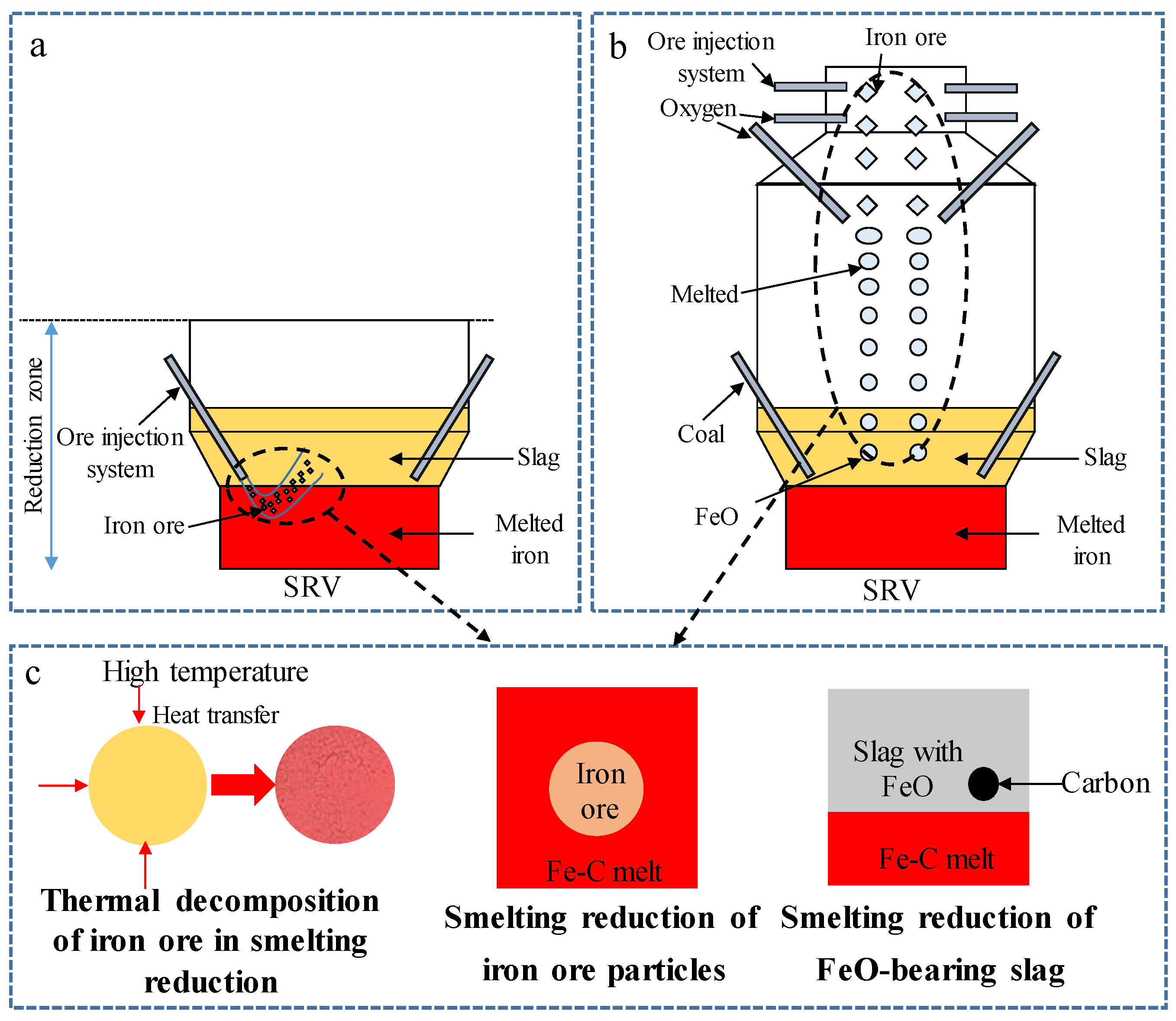
2. Progress on the Thermal Decomposition Characteristics of Iron Ore during Smelting Reduction

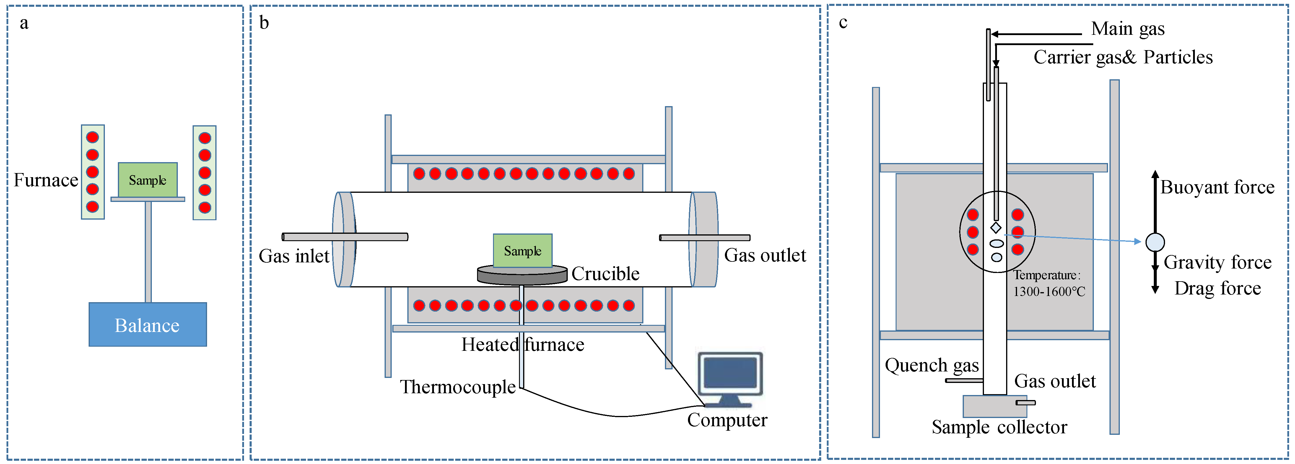
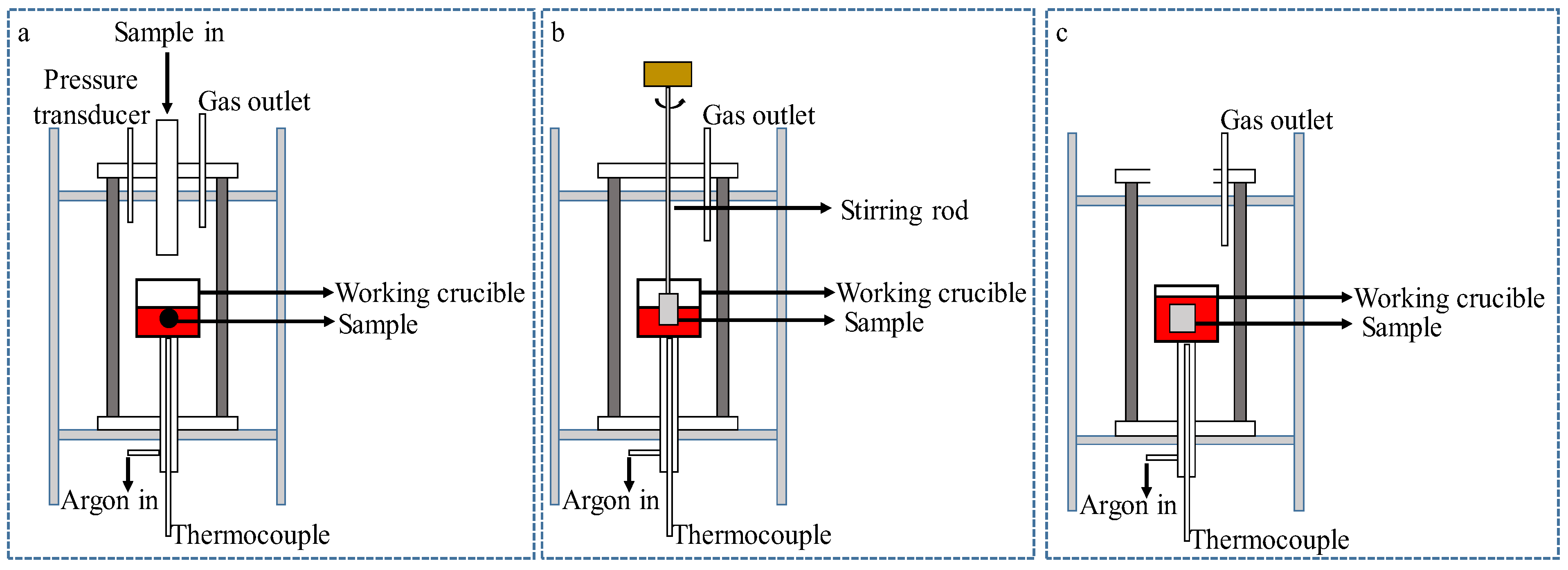
2.1. Research Progress of Experimental Methods

Iron ores used in the bath smelting reduction technology are generally hematite or hematite–limonite ore, minerals that contain Fe2O3, FeO(OH), SiO2 and Al2O3. The iron ore undergoes thermal decomposition reactions in a high-temperature environment due to heat transfer during smelting reduction.
For the study of the thermal decomposition behavior of iron ore during smelting reduction, previous experimental methods included a thermogravimetric analysis (TGA) device, a heated horizontal furnace, and a high-temperature drop tube furnace, as shown in Figure 2 [25]. This method is used to investigate the thermal decomposition temperature and properties of iron ores via the thermal decomposition temperature and mass weight loss of the sample at different heating rates. The TGA device (as shown in Figure 2a) is often used in combination with differential scanning calorimetry (DSC) equipment to test the endothermic peak at different heating rates. It requires a smaller sample mass, and it is more difficult to test the chemical composition of the sample with it after a reaction than other experimental methods are.
The heated horizontal furnace (as shown in Figure 2b) allows for experiments to be performed on a large number of samples, and samples at room temperature could be pushed directly into the constant temperature area for the thermal decomposition of samples at a constant temperature. Its advantage is that the chemical composition of a sample can be detected at different reaction times, and the atmosphere of experiment can be changed.
Figure 2c shows the high-temperature drop tube furnace that produces the thermal decomposition characteristics of iron ore during the falling process; therefore, it is closer to the actual environment of the HIsarna process. The method allows for the thermal decomposition characteristics of iron ore to be studied at different residence times, particle sizes, and temperatures, and in different atmospheres.

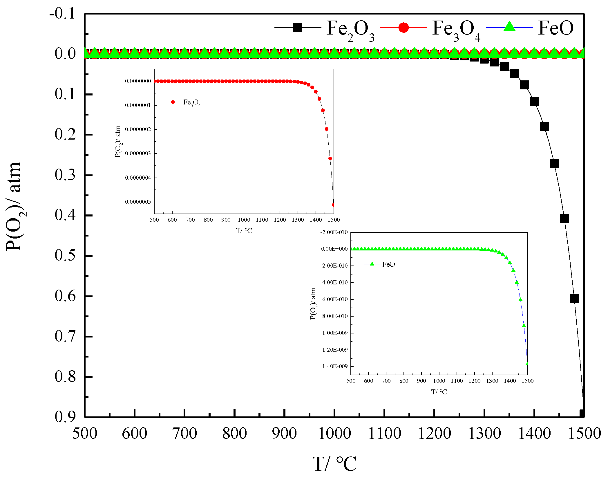
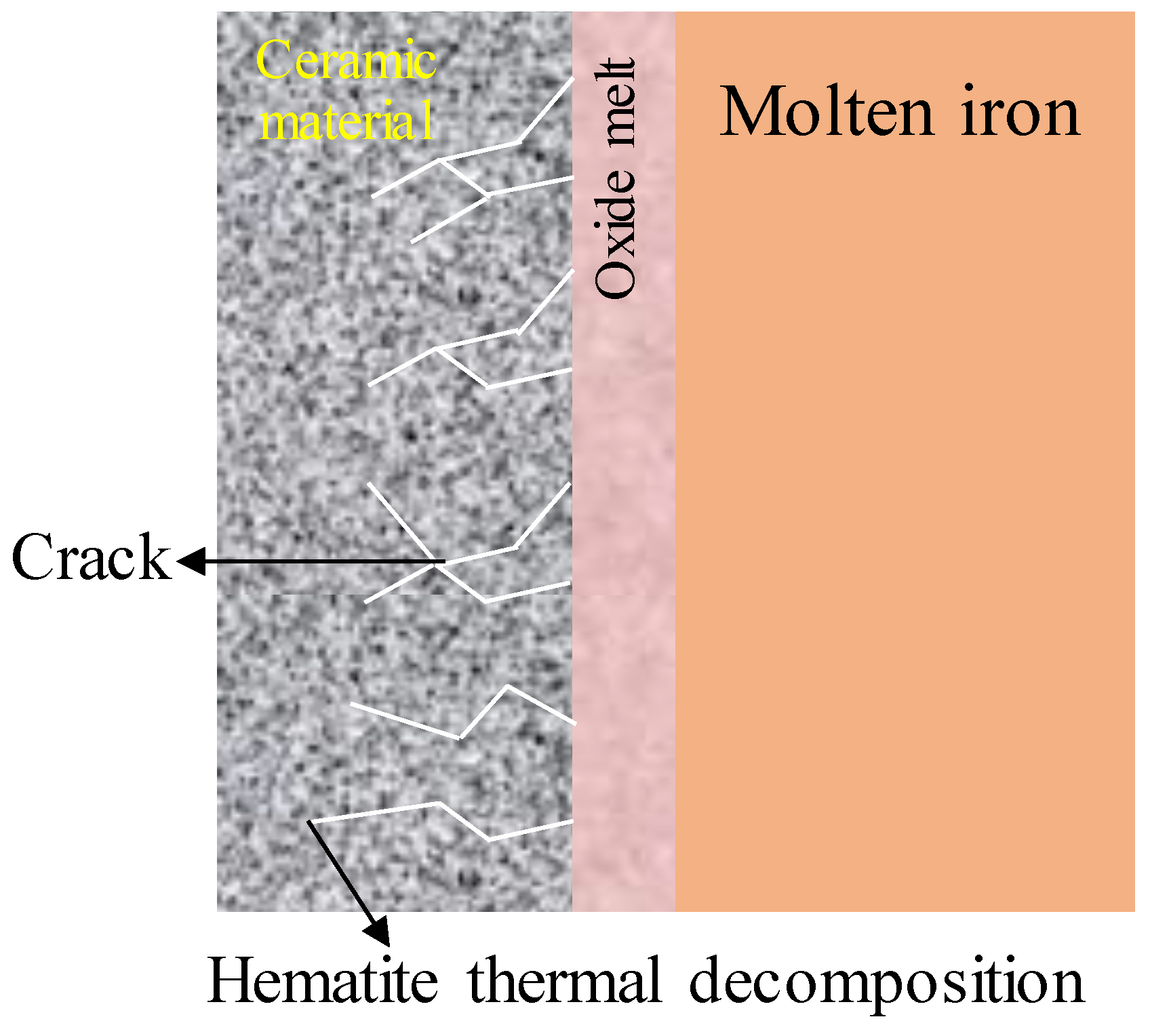
2.2. The Thermal Decomposition Reaction Mechanism and Influencing Factors of Iron Ore

The thermal decomposition of iron ore involves the decomposition of hematite and hydrated minerals (such as goethite, kaolinite, and gibbsite). Goethite, as a mineral produced through the weathering of hematite, contains crystalline hydrate. Its thermal decomposition reaction is the process of dehydration into hematite. Wolska’s study showed that goethite is converted into primary hematite, then into hydrogen hematite, and lastly into hematite in the pyrolytic process [26]. Goethite is converted directly into hematite during thermal decomposition without the formation of any intermediate phases [27,28]. The thermal decomposition reaction of goethite is shown in Equation (1):
2 F e O O H ( s ) = F e 2 O 3 ( s ) + H 2 O ( g )
The thermal decomposition temperature of hematite is higher than that of goethite. The step-by-step reaction process of the Fe2O3 decomposition is shown in Equations (2)–(4) [29]:
6 F e 2 O 3 ( s ) = 4 F e 3 O 4 ( s ) + O 2 ( g )             Δ G 0 = 586770 340.2 T     J / mol
2 F e 3 O 4 ( s ) = 6 F e O ( l ) + O 2 ( g )             Δ G 0 = 858200 392.6 T     J / mol
2 F e O ( l ) = 2 F e ( l ) + O 2 ( g )             Δ G 0 = 256061 53.7 T     J / mol
The results of partial oxygen pressure for the decomposition of iron oxides (Fe2O3, Fe3O4 and FeO) at different temperatures were calculated with FactSage, as shown in Figure 3. Partial oxygen pressure during the decomposition of Fe2O3 at 500 and 1000 °C was 9.4505 × 10⁻²⁰ and 1.7968 × 10⁻⁶ atm, respectively. The partial oxygen pressure of hematite’s thermal decomposition at 1400 and 1500 °C was 0.1175 and 0.8919 atm, respectively. The partial oxygen decomposition pressure of Fe3O4 500 and at 1500 °C was 5.2033 × 10⁻³⁰ and 5.1294 × 10⁻⁷ atm, respectively. The partial oxygen decomposition pressure of FeO at 1500 °C was 1.3700 × 10⁻⁹ atm. Hematite is more difficult to decompose into magnetite at low temperatures, and easier to decompose at high temperatures to produce magnetite. The decomposition reaction of Fe3O4 and FeO at normal pressure levels does not occur below 1500 °C.
The decomposition products of hematite at 1400 and 1500 °C are solid magnetite, and liquid magnetite and FeO at 1600 °C [25]. Optical-microscopy observations based on the thermal decomposition process of hematite also indicated that the core unreacted mineral is hematite, and the edge decomposition product is magnetite [29]. The results of the study correspond to the theoretical calculations in Figure 3.
Factors affecting the thermal decomposition of iron ore include the system atmosphere, particle size, and residence time at high temperatures. The results of the relevant studies are as follows.
(1)
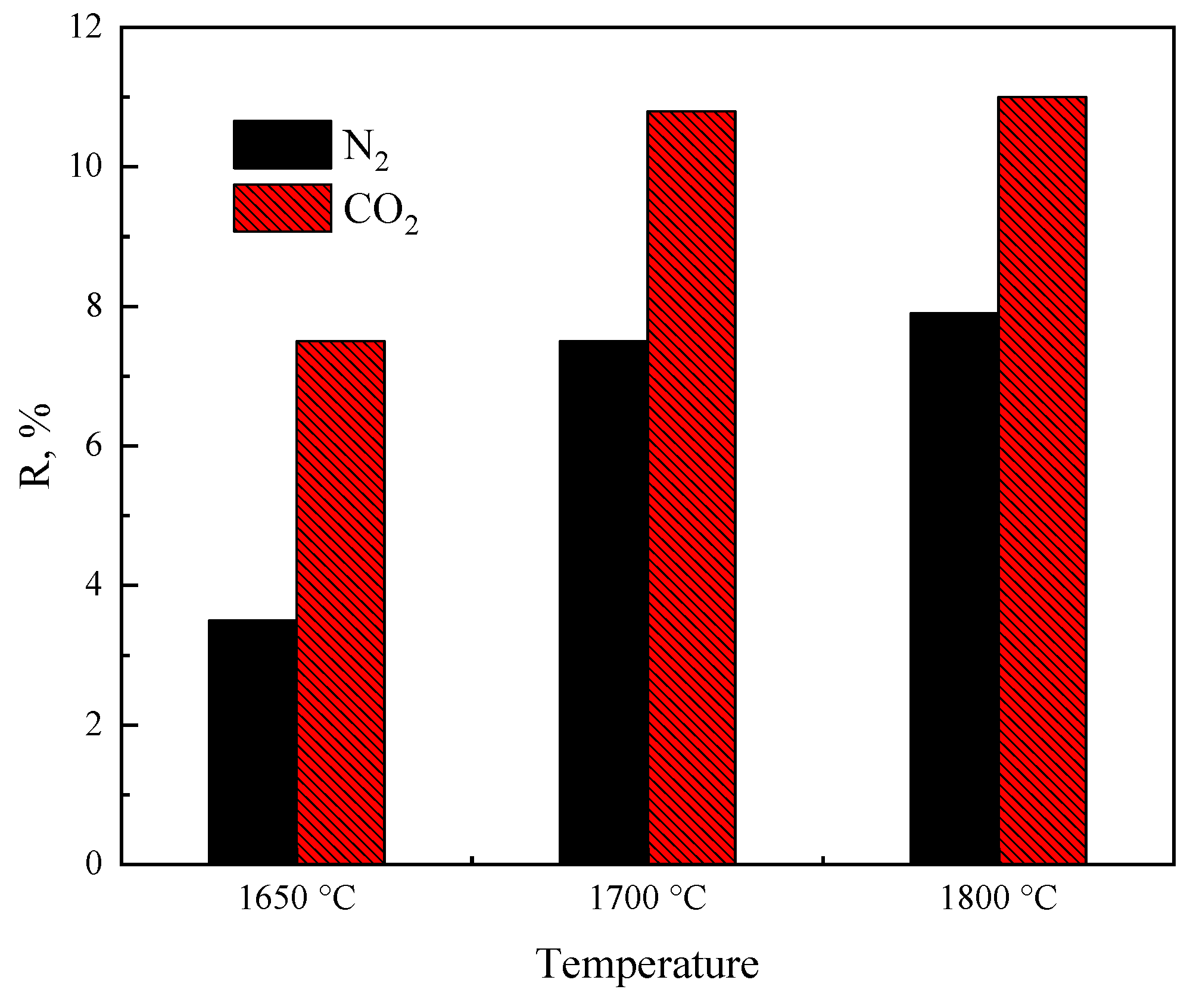
The influence of atmosphere
Monica et al. [30] investigated the thermal decomposition of hematite (α-phase, 99% metal basis) with TGA, with the first and second decomposition peaks at 358 and 600 °C, respectively. Mohammad et al. treated hematite up to 1450 °C in an inert (N2) and air atmosphere [31], and showed that the decomposition reaction of hematite occurred at 1180 °C in the inert atmosphere and was basically completed at 1270 °C. However, the decomposition of hematite started at 1360 °C in the air atmosphere. Qu et al. [25] found that the decomposition temperature of hematite was 1264 °C at a heating rate of 10 °C/min. Darken et al. [32] also reported that hematite’s decomposition temperature was 1264 °C in an inert atmosphere, 1457 °C in an oxygen atmosphere, and 1392 °C in an air atmosphere. Hematite decomposes at a temperature of 1385 °C in an air atmosphere [33]. The decomposition temperature of hematite is lower and lasts longer in an inert atmosphere than it does in an air atmosphere. The results of the partial oxygen pressure for the decomposition reactions calculated with FactSage show that the partial oxygen pressure of the system was lower in the inert atmosphere, and its decomposition temperature was thereby lower. However, even for the same atmosphere, previous studies on the decomposition temperature of hematite vary, with large differences in the decomposition temperature.
In addition, the differences in the decomposition behavior of hematite in CO2 and inert (N2) atmospheres were compared by previous authors [25]. The oxygen loss percentage (R) is the ratio of the weight loss of oxygen of a sample, Δmoxygen, to the total oxygen mass of the iron oxide in sample, mtot-oxygen, as shown in Equation (5).
R = Δ m o x y g e n m t o t o x y g e n
The R of hematite in CO2 atmosphere was 3–4% higher than that in the N2 atmosphere, as shown in Figure 4. This is mainly related to the structure of the gas molecules, as CO2 has a higher thermal radiation capacity than that of N2, as the particles heat up faster through radiation in a CO2 atmosphere than they do in an N2 or Ar atmosphere [25].
(2)
Particle size
Monica et al. [30] found that the decomposition temperature of fine-grained hematite (99% metal basis) was lower after ball milling, and that the grain size had an important influence on the thermal stability of hematite. Similarly, in TGA–DSC experiments, the initial decomposition temperature was 1383 °C for 125–250 μm hematite and 1264 °C for 45–53 μm hematite on the basis of a 10 °C/min heating rate, showing that the decomposition temperature increased for the larger iron-ore fines due to the slow heating rate [25]. However, TGA thermal decomposition experiments with different hematite particle sizes of −110 μm were also conducted, and the results showed that the particle size of hematite had no significant effect on the thermal decomposition temperature [29].
However, in the thermal decomposition experiments based on a high-temperature drop tube furnace, the variation in iron-ore particle size had no effect on the weight loss of its thermal decomposition when both were −250 μm, mainly because the decomposition of hematite into magnetite had been completed before it fell to the bottom [25]. Although the particle size causes changes in the decomposition temperature, it is not a major factor in the HIsarna bath smelting reduction process, and decomposition was completed with the falling process in CCF.
(3)
Residence time/Heating rate
For the decomposition of goethite, an increase in residence time leads to an increase in its weight loss, suggesting that the heating rate is the limiting step in its thermal decomposition. Xing et al. [29] showed that the start and end temperatures of the thermal decomposition reaction in the TGA experiments increased with the heating rate. There is hysteresis in the reaction at faster heating rates. The residence time of iron ore with N2 in the vertical furnace had a significant effect on the thermal decomposition, while the residence time in CO2 atmosphere had no effect on the thermal decomposition, indicating that the heating rate of the particles is the limiting step of thermal iron-ore decomposition in an N2 atmosphere.

2.3. Study of the Kinetics of Iron Ore Thermal Decomposition

The kinetic behavior of thermal iron-ore decomposition reactions has been extensively studied by previous authors. The main investigations regarded the rate-controlled model of thermal decomposition reactions and the activation energy of the reactions. The activation energy characterizes the ease of the thermal iron-ore decomposition reaction and is the energy absorbed by the reactant molecules to convert them from a stable state into activated molecules. The activation energy of hematite decomposition is higher than that of hematite–limonite ores.
Beuria [34] investigated the kinetics of the thermal decomposition of hematite–limonite ore. The rate-limiting model of thermal decomposition reaction is dominated by random nucleation and chemical reaction control. At higher temperatures, the random nucleation model dominates the thermal decomposition process. The random nucleation and chemical reaction models for the thermal decomposition reaction are shown in Table 2.
For the study of goethite’s kinetic model’s thermal decomposition, previous studies showed that the thermal decomposition process of goethite is controlled by the random nucleation with nucleation growth models [35,36,37]. The activation energies for the decomposition reactions of goethite were also extensively reported, and the results of previous studies for the activation energies of goethite decomposition are shown in Table 3. The activation energy for decomposition was around 80 kJ·mol−1 for most researchers, with some activation energy values varying considerably.
For the kinetic study of the thermal decomposition reaction, previous studies had consistent results regarding its thermal decomposition kinetic model, but they vary considerably for the activation energy of decomposition reactions.
The activation energy of the thermal decomposition of hematite has also been extensively studied with the isoconversion method. The activation energy of hematite in air and inert atmospheres was 382 and 324 kJ/mol through an isoconversion methodogy, respectively. The activation energy calculated with the DSC method was significantly higher than the values achieved with TG [31]. However, two stages of the thermal decomposition of hematite in an inert atmosphere were reported with activation energies of 636 and 325 kJ/mol [33,43]. Xing’s results indicated that activation energy for the thermal decomposition of hematite was 1256 kJ/mol with a pre-exponential factor of 1.94 × 1041 s−1 with the TGA method [29].

3. Progress on the Smelting Reduction of Iron-Ore Particles

3.1. Research Progress of Experimental Methods

When iron-ore particles are injected into a liquid iron bath melt, the key aspect of the smelting reduction process involves the smelting reduction reaction between the solid iron-ore particles and the liquid melt. The main adopted research approaches are shown in Figure 5.
The gas testing method (as shown in Figure 5a) focuses on the characterization of the reduction gas produced by the smelting reduction reaction, as shown in Equation (6). The method can be used to calculate reduction rates using the CO gas flow generated during experiments [44], and reaction rates using a pressure detector to determine changes in pressure within the sealed system [45].
F e x O y + y [ C ] = x F e + y C O ( g )
The rotating cylinder method (as shown in Figure 5b) is used to characterize the smelting reduction process and investigate the effect of different factors on the smelt reduction reaction by rotating the sample after it had been immersed in the melt for a period of time. The method is suitable for experiments with slower reaction rates [46,47,48,49].
The breakpoint experiment method (as shown in Figure 5c) involves throwing experimental sample directly into a high-temperature melt and using the disappearance time of the sample as the smelting reduction time. During this process, samples can be raised for quenching, and used to study the microscopic interfaces and phase evolution during the reaction [50,51,52].

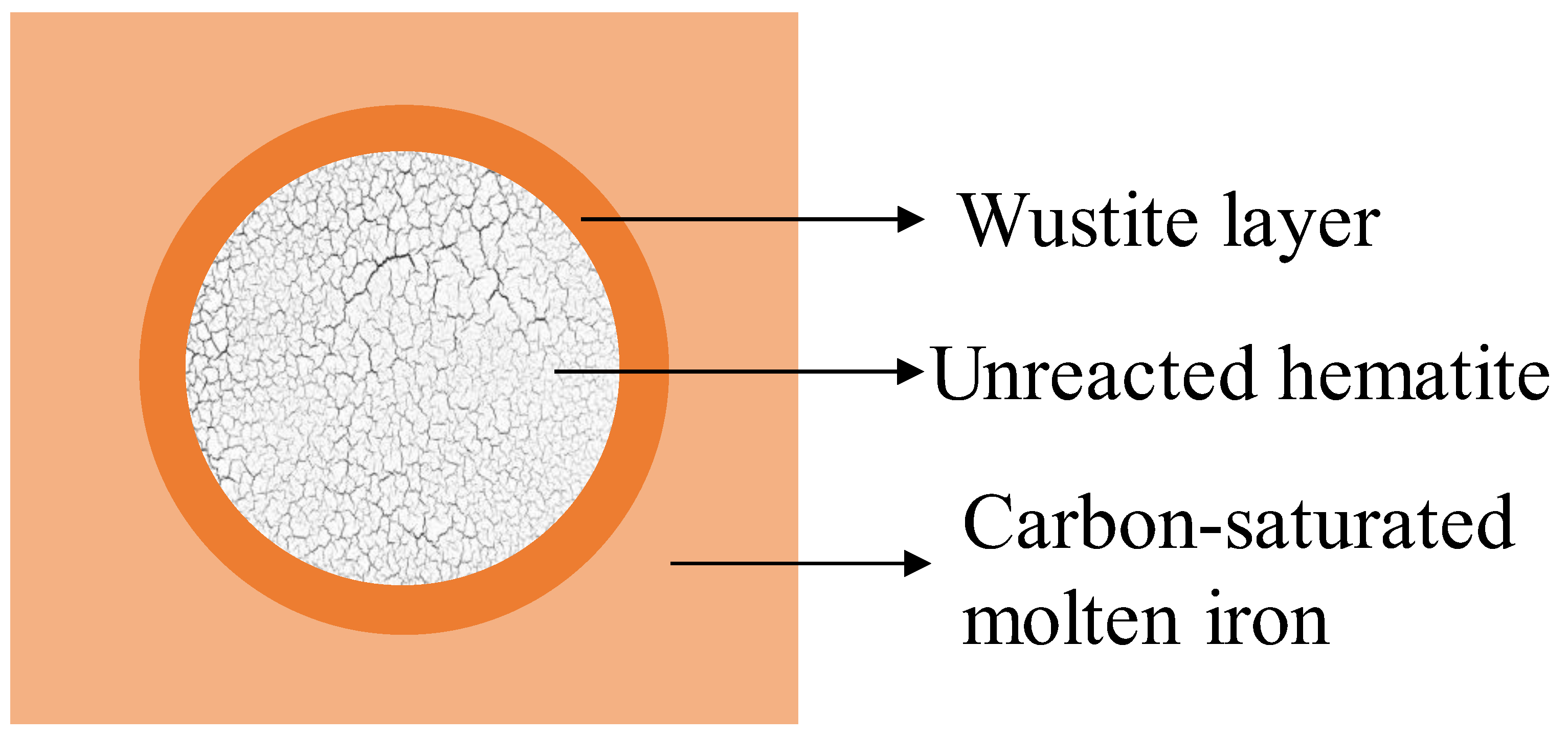
3.2. Solid Iron-Ore Smelting Reduction Mechanisms and Influencing Factors

Udalov et al. [53] investigated the interactions between solid materials containing hematite and liquid molten iron, which began with the thermal decomposition of hematite and the formation of a FeO layer at the interface. The schematic diagram is shown in Figure 6. The hematite in the ceramic material undergoes thermal decomposition reactions at high temperatures, and the O formed by decomposition reacts with the molten iron to form wüstite. When the solid material contains Al2O3, wüstite reacts with Al2O3 to form a FeAl2O4 spinel phase [54,55]. Ceramic materials containing hematite form a four-zone structure when combined with molten iron: the solid material zone, the reduced wüstite zone, the decomposition-generated gas zone, and the molten-iron zone [56]. However, the molten iron in these studies is liquid metallic iron without carbon.
Interfacial reactions, and the phase evolution of iron oxides and carbonaceous iron were also extensively investigated. Marcelo [45] observed an interfacial phase evolution between hematite pellets and carbon-saturated molten iron via scanning electron microscopy. Figure 7 illustrates the phase evolution of a hematite pellet during its smelting reduction in an iron bath, with a continuous wüstite layer at the edge of pellet. There was unreacted hematite inside [45]. The the reaction of iron oxides with Fe–C melts results in the formation of FeO layers between them that are then reduced into the metallic iron phase.
For the reaction process of the smelting reduction of solid iron oxides with [C] in the melt, the whole reaction may be limited by the formation of FeO and the production of reducing gas CO. The reaction process is shown in Equations (7)–(9).
F e 2 O 3 ( s , l ) + F e = 3 F e O ( s , l )
F e O ( s , l ) = F e ( s , l ) + O _
C _ + O _ = C O ( g )
As the main raw material for smelting master batches of stainless steel, chromite is usually added to carbonaceous iron to increase the chromium content of the molten iron. Within iron containing [C] and [Si], the smelting reduction reaction of chromite proceeds mainly through Reactions (10) and (11) [48].
FeCr2O4(s) + 4[C] = Fe(l) + 2Cr(l) + 4CO(g)
FeCr2O4(s) + 2[Si] = Fe(l) + 2Cr(l) + 2SiO2(l)
The smelting reduction rate of iron-ore particles in molten iron is mainly limited by factors such as melt composition, melt temperature, and the particle size and weight of iron-ore particles. The relevant studies are as follows:
(1)
Melt composition
The dissolution rate of chromite in slag is altered by changes in the composition of the slag system. The reduction rate decreases with increasing slag alkalinity (0.8 to 1.6), Al2O3 content (10 to 20 wt %), and MgO content (5 to 15 wt %). A decrease in the liquid phase temperature and viscosity of the slag system also leads to an increase in the dissolution rate [50].
The increase in [C] content within a Fe–C–Si melt promotes the smelting reduction process of chromite, mainly because the higher [C] content increases [C] activity and reduces equilibrium O content within the melt. In addition, the lower oxygen content increases the driving force for oxygen diffusion at the pellet interface [47].
(2)
Melt temperature
For the smelting reduction reaction of chromite in Fe–C–Si melts, high temperatures could facilitate the endothermic decomposition reaction of iron oxides. In addition, high temperatures increase the rate of element diffusion in the solid and liquid phases, so increasing the temperature facilitates the smelting reduction reaction [47]. The findings of Demir et al. are consistent with this [48]. When the iron oxide is reduced in a Fe–C melt, the rate of reduction increases because the melting of FeO increases the contact area between the iron oxide and melt at 1487 °C [44].
(3)
Particle size and mass of iron ore
For the dissolution of chromite in slag, particle size had an important influence on the dissolution rate, with small particles increasing the area of the chromite and reaction boundary, and accelerating the dissolution rate [50]. Marcelo measured the reaction time for different types of pellets at different temperatures according to the gas testing method, and fitted the relationship between reaction time and pellet mass. For the same type of pellet, the reaction time decreased with increasing pellet mass and temperature, and showed a good linear relationship. The reaction time depended on the contact area between the pellets and melt in an experimental bath-dissolution study of the same mass and different numbers of pellets [45].

3.3. Study of the Kinetic of Solid Iron Ore Smelting Reduction Reaction

To investigate the smelting reduction limiting step of chromite, Liu et al. [50] investigated the dissolution process of chromite in a CaO–SiO2–MgO–Al2O3 slag system and characterized the dissolution rate via the mass change in chromite. After the dissolution of the chromite surface had begun, the liquid product rapidly diffused into the slag through the surface boundary layer. Therefore, the dissolution reaction was limited by the surface dissolution reaction.
On the basis of the interfacial dissolution reaction as the limiting step of chromite in slag, the kinetic model of chromite in converter slag is shown in (12) [50]:
t = ρ P r 0 k r [ 1 ( 1 f ) 1 / 3 C C r 2 O 3 * C C r 2 O 3 i ]
where kr is the apparent rate constant for dissolution reaction, C C r 2 O 3 i is the molar concentration of Cr2O3 at the surface of chromium ore, C C r 2 O 3 * is the molar concentration of Cr2O3 for saturation solubility in slag, ρP is the molar density of chromium ore; r0 is the initial radius of a chromium ore particle, and f is the dissolution ratio of chromium ore.
Ding et al. explored the smelting reduction process of chromite pellets within Fe–C–Si and Fe–Cr–C melts. The first stage is the reduction of the solid pellets, the second stage is the dissolution and melting over of the pellets, and the third stage is the interfacial slag–gold reaction after melting. Heat transfer had an important influence on the reaction during the initial phase, of which the limiting step is the interfacial chemical reaction with a reaction activation energy of 472 kJ/mol [46].
Demir et al. showed that the reduction rate of chromite in Fe–Cr–C melts is controlled by the liquid phase transfer of oxygen with a reaction activation energy of 92.9 kJ/mol [48]. The apparent activation energies of [C] in molten-iron-reduced iron oxides obtained in previous studies fluctuated widely, ranging from a minimum of 76.2 ± 27.7 kJ/mol to a maximum of 234 kJ/mol [44].

4. Progress on the Smelting Reduction of FeO-Bearing Slags

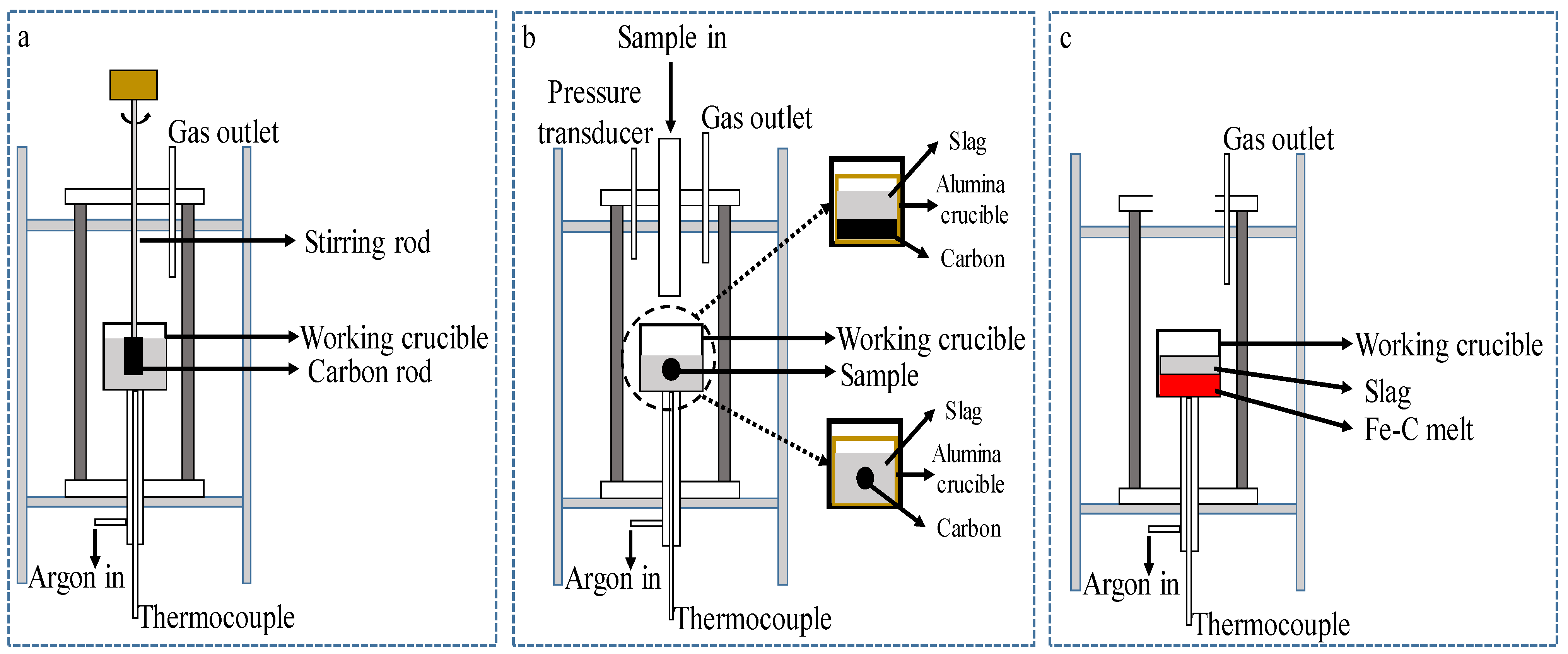
4.1. Research Progress of Experimental Methods

For the study of the smelting reduction reaction between liquid iron oxide and molten iron or carbon-containing materials, the experimental methods used by previous authors are shown in Figure 8 [5,57,58,59,60].
Figure 8a shows that rotating a carbon rod within slag containing FeO can be used to determine whether the limiting step of the smelting reduction reaction contains the mass transfer of FeO.
Figure 8b shows the smelting reduction process based on the pressure of gas generated by reduction reactions where the smelting reduction rate is calculated by measuring the volumetric flow rate of the exhaust gas or by using the mass spectrometer technique [61,62]. Solid carbon can be placed at the bottom or the particles can be thrown into the slag.
The method shown in Figure 8c can be used to conduct smelting reduction experiments between slag and Fe–C melts. The reaction rate of the experimental process is calculated from the chemical composition of the slag sample, the overall weight loss of the crucible, or via the reaction gases, as in the method shown in Figure 8b. These experimental methods could be observed by using X-ray fluoroscopy.

4.2. Smelting Reduction Reaction Mechanism of FeO-Containing Slag and Influencing Factors

In the smelting reduction process, a large proportion of molten iron oxides in slag are reduced to iron by the solid carbon particles or carbon dissolved in the molten iron.
When molten iron oxide in slag is reduced by solid carbon, numerous previous studies have shown that the total reaction of FeO-bearing slag with solid carbon can be indicated with Equation (13), and the reaction process is shown in Figure 9.
( F e O ) ( l ) + C ( s ) = F e ( s ) + ( C O ) ( g ) < 1808 K
where (FeO) denotes the FeO dissolved in slag, and C represents solid carbonaceous material in the slag. As shown in Figure 10, the smelting reduction process of FeO in slag consists of five separate steps.
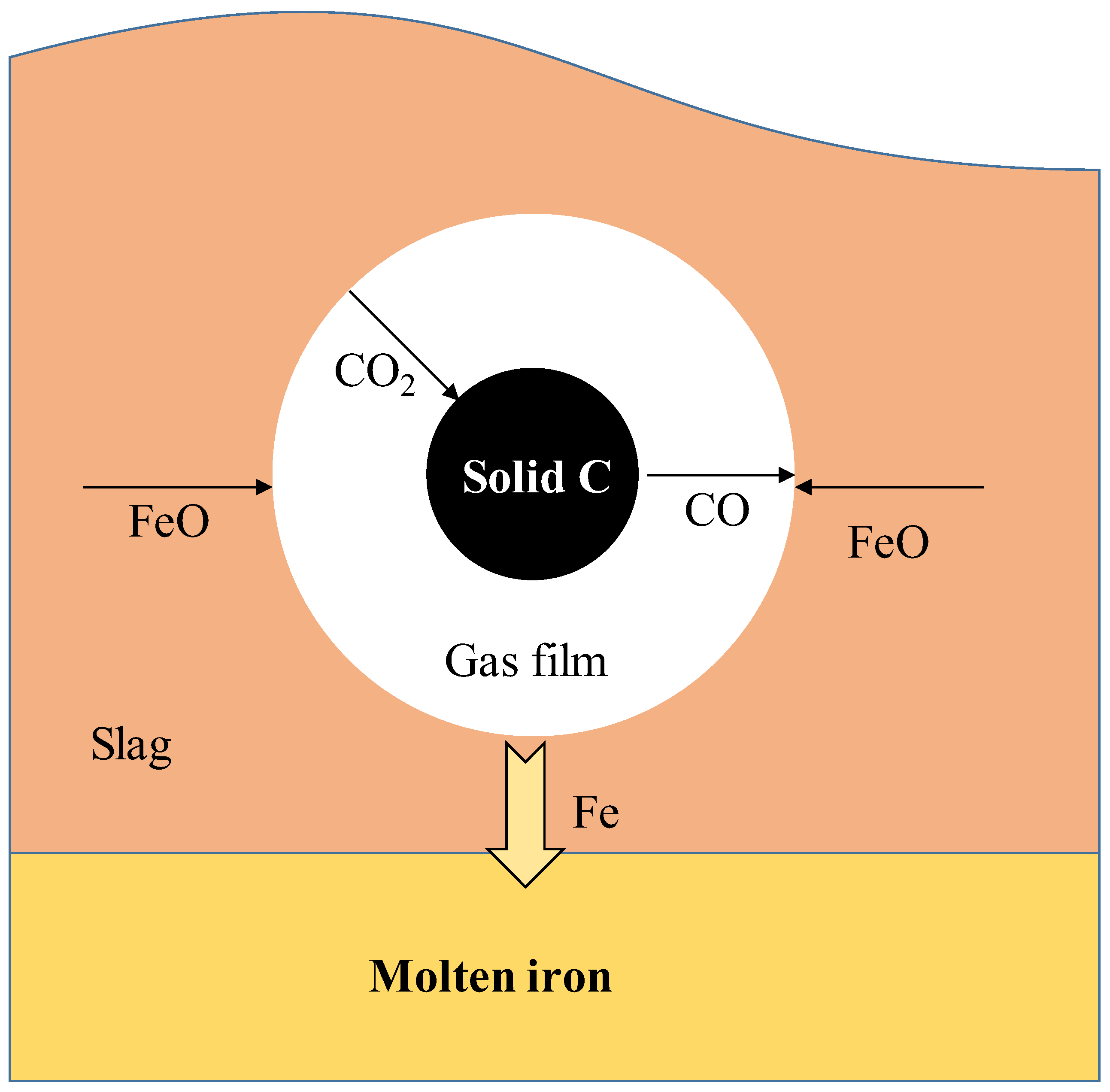
  • Chemical reactions at the gas–slag interface, as shown in Equation (14):
( F e O ) ( l ) + ( C O ) g = F e ( l ) + ( C O 2 ) g
  • Chemical reactions at the gas–carbon interface, as shown in Equation (15):
( C O 2 ) ( g ) + C ( s ) = 2 C O ( g )
  • Diffusion of FeO from the slag to the gas–slag interface.
  • Diffusion of CO2 into solid carbon through the gas halo.
  • Diffusion of CO into gas–slag interface through the gas halo.
The results of Amitava et al. [58] showed that the whole reaction of FeO reduction by dissolved [C] in melt is shown in (16). Reactions (16) can be divided into gas–slag interface Reaction (17) and gas–metal interface Reaction (18)
( F e O ) + [ C ] = F e + ( C O ) g
( F e O ) + ( C O ) g = F e + ( C O 2 ) g
( C O 2 ) g + [ C ] = 2 ( C O ) g
According to Reactions (17) and (18), the various steps for the reduction of FeO by carbon dissolved in molten iron can be written as follows:
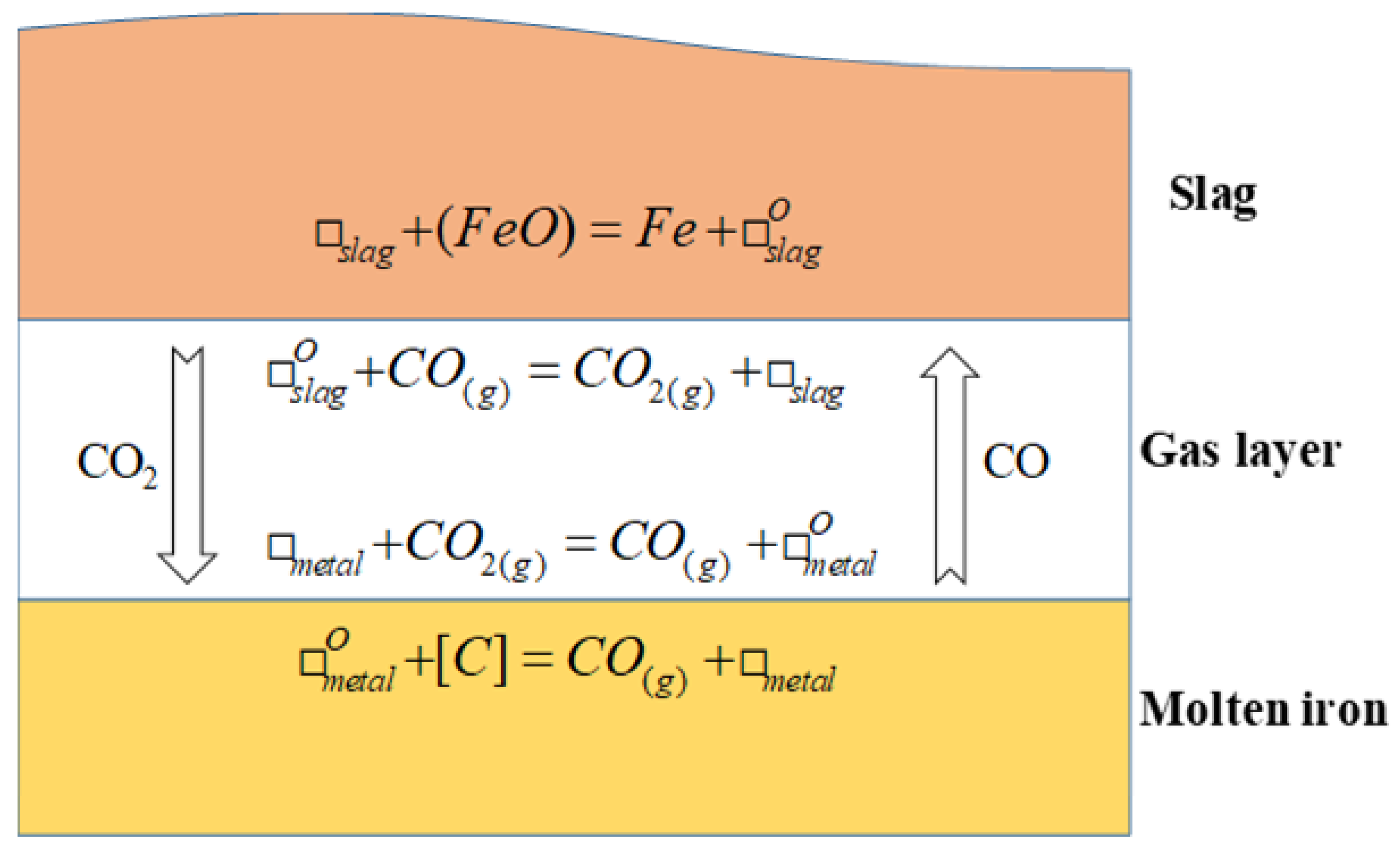
  • [C] in the molten iron is transported to the gas–metal interface.
  • Chemical Reaction (18) occurs at the gas–metal interface.
  • Gas transfer from the gas–metal interface to the gas–slag interface.
  • FeO in the slag is transported to the gas–slag interface.
  • Chemical Reaction (17) occurs at the gas–slag interface.
On the basis of the above reaction steps, the schematic diagram of the smelting reduction of FeO in slag by [C] is shown in Figure 10. s l a g represents an available vacant site for the adsorption of oxygen on the slag surface; m e t a l represents the available vacant site for oxygen adsorption on the metal surface; index “O” indicates a site occupied by adsorbed oxygen in the slag and metal, respectively. In this case, the diffusion of [C] within the carbon saturated melt (Step 1) can be basically neglected as the rate-controlling step.
During the smelting reduction of FeO-bearing slag, reaction product CO produces a gas film to separate the carbonaceous material from the slag, which also leads to slag blistering. Previous studies showed that the diffusion and interfacial chemistry of iron oxides in slag are rate-limiting steps in low-FeO slag, and the interfacial chemistry reaction is the limiting step within medium-to-high-FeO slag.
Factors influencing the smelting reduction rate of FeO in slag are mainly FeO content and carbonaceous material. The specific results of previous studies are as follows.
(1)
FeO content in slag
The FeO content of slag affects its mass transfer process, and the limiting step of the reaction differs at different levels of FeO. At low FeO mass content in the slag (<5 wt %), the smelting reduction process is controlled by two steps: the mass transfer of FeO in slag and interfacial gas–metal chemical reaction. At medium FeO mass content (5–40 wt %), the process is controlled by three steps, i.e., gas–metal interface chemistry reaction, gas–slag interface chemistry reaction, and FeO mass transfer in the slag phase. When the FeO content is high (>50 wt %), the process tends to be a mixed chemical reaction controlled by a gas–metal interface chemistry reaction and a gas–slag interface chemistry reaction [58]. Min et al. [62] found that, at low FeO content (<5 wt %), the mass transfer rate of FeO in liquid slag is limited, while at high FeO content (>30 wt %), the chemical reaction at the gas–carbon interface is the limiting step that controls the reaction rate. The limiting step of the FeO smelting reduction of slag at different FeO contents is shown in Table 4.
(2)
Carbonaceous materials
Khasraw et al. [5] compared the smelting reduction effect of thermal coal (TC) and charcoal (CC) on the slag system of the HIsarna process; the reduction of CC was better for FeO than that of TC. The results of the reduction rates of different carbonaceous materials in FeO-bearing slag showed that the reduction rates of fixed coke rods were slightly worse than those of graphite rods. This is mainly because coke contains a certain amount of ash that hinders the direct contact between slag and solid carbon as the reduction time increases. However, in the smelting reduction experiments with static carbonaceous spheres and horizontally placed carbonaceous materials, the reduction rate for spheres or horizontal surfaces with coke was higher than that for graphite in slag with 8 wt % FeO [57]. No detailed mechanistic explanation was previously given for the differences in these experimental situations.
Different carbonaceous materials react at different degrees with CO2, which is critical for CO production and thereby affects the smelting reduction rate [62,64]. Therefore, the carbon gasification step is defined as a control mechanism. Story et al. [64] found that the type of carbon had a significant effect on the reduction rate. However, Seo et al. [65] showed that the reduction rate of FeO in slag is independent of the type of coal. Therefore, whether the type of carbon-containing material had an effect on the smelting reduction of FeO in slag needs further investigation.
Furthermore, when Khasraw et al. [5] used carbonaceous materials to reduce FeO in a CaO–SiO2–Al2O3–MgO–FeO slag system, the temperature had a large effect on the reduction index of FeO in carbon reduction slag, and the reduction index increased with increasing temperature. Temperature had a significant effect on the variation in gaseous products CO and CO2.

4.3. Study of the Kinetics of the Smelting Reduction Reaction of FeO-Bearing Slag

For the smelting reduction rate of FeO-bearing slag, the reduction rate is a function of FeO content in the slag. The reaction rate measured in previous experiments is an n-order relationship for (wt % FeO), with n is being close to 2. In general, the mass transfer coefficient of FeO in slag depends on the fluid flow conditions in slag. If the flow conditions are natural convection, the diffusion distance (boundary-layer thickness) is determined via the fluid flow in system, which is driven by the presence of a density gradient. If flow conditions are controlled by natural convection, the rate linearly varies with FeO content. The turbulent conditions that may occur due to rod rotation and CO gas precipitation lead to the forced convection of the liquid and a further reduction in the boundary layer thickness, resulting in a reaction number (n) close to 2.
Sarma et al. [57] investigated the reduction rate of graphite rods in FeO-bearing slag at different rotation speeds. The increase in graphite rod speed also increased the reaction rate from 3.56 × 10⁻⁷ mol·cm−2·s−1 when fixed without rotation to 6.3 × 10⁻⁷ mol·cm−2·s−1 at 2.35 wt % FeO at 185 rpm. The liquid-phase mass transfer of FeO in slag is a limiting step in smelting reaction process. For the reduction of FeO with solid carbon in a slag system, limiting steps are different for different stages of the smelting reaction. The first stage of the reaction is represented by secondary model F2, with activation energies in range of 229–290 kJ/mol. The reaction rate at the first stage is controlled by the chemical reaction at the solid–carbon interface, and the reaction rate at the second stage is described by a three-dimensional diffusion model (D3) that may be influenced by a mixture of gas diffusion, liquid-phase mass transfer, chemical reaction, and carbon diffusion [5]. The integral form of the F2 model is shown in Equation (19), and the integral model of D3 is shown in Equation (20); α is the conversion rate of the reaction.
F 2 : G ( α ) = ( 1 α ) 1 1
D 3 : G ( α ) = [ 1 ( 1 α ) 1 / 3 ] 2
Sarma et al. [57] showed that the n value changed with FeO content, with an n (reaction order) of 1.43 for 5 wt % FeO in slag and 1.67 for 5–10 wt % FeO in slag. Bafghi et al. [66] investigated the effect of slag foaming on the reduction of FeO in slag. The results showed that slag foaming had an effect on smelting rate, and that the liquid phase transfer was the limiting step in the smelting reduction rate. Smith et al. [67] investigated the reduction rate of FeO in slag by carbon in melts with different sulfur content at 1450 °C. At a high sulfur content (0.2 wt %), the reaction was limited by the interfacial gas–metal reaction, and at low sulfur content (0.003 wt %), it was limited by the FeO mass transfer and gas–metal mixing control mechanism.
The results of Ding et al. equally indicated that, at the third stage of a chromite pellet’s smelting reduction (i.e., reaction between slag and metal), the rate-controlling step was the mass transfer process of slag [46]. The process of Fe–C melt reduction of iron oxide (FeO < 5% in slag) was studied and showed that the gas–gold interface reaction was the rate controlling factor. The smelting reduction of FeO (5 % FeO in slag) with metal droplets was also studied, and for metals with more than 2–3 % C content (in metal droplets), the reduction rate of FeO was controlled by the mass transfer of FeO in slag.
The results of the smelting reduction reaction rate and the activation energy of FeO under different experimental conditions are further summarized in Table 5. For the smelting reduction reaction between [C] in molten iron and iron oxides in slag, the reduction rates obtained by different scholars vary relatively little, but the activation energy values widely vary, which may be mainly attributed to the different experimental conditions. The reduction rates of the solid carbon and dissolved carbon of molten iron differed significantly.

5. Conclusions

In this study, the thermal decomposition characteristics of iron ore, the smelting reduction mechanism of iron-ore particles, and the smelting reduction mechanism of FeO-bearing slag in bath smelting reduction process were reviewed and studied, focusing on the experimental study methods, reaction mechanisms, influencing factors, and kinetic behaviors of the three key aspects above. Our main conclusions are as follows.
(1)
For the study of the thermal decomposition of iron ore in the smelting reduction process, the reaction mechanism of goethite and hematite decomposition was clearer. However, discrepancies in previous studies regarding the decomposition temperature, especially the influence of different factors (particle size, heating rate, and high temperature-residence time) on it, need to be further clarified. In addition, there are differences between the current experimental conditions and the actual process conditions of iron ore’s thermal decomposition, so the falling process of iron ore within SRV and the thermal decomposition within the molten iron need to be further investigated. The correlation between the internal cracking characteristics during thermal decomposition and the subsequent smelting reduction reaction was also analyzed.
(2)
Research was advanced on the smelting reduction of solid iron-ore particles within a melt: For the melt temperature, the composition and particle-size factors on the smelting reduction influence rule, the results of previous studies are more consistent. However, the effect of the particle size of the iron ore used in smelting reduction process on reduction rate needs to be further investigated. Previous studies clarified the existence of a liquid FeO layer between iron-ore particles and the melt in the reduction mechanism, but the specific smelting reduction mechanism and the phase evolution need to be further explored. In terms of kinetics, the study of the rate-controlling step of the reaction is still unclear, the values of the reaction activation energy derived vary greatly, and the limiting steps of the reaction and activation energy values need to be further clarified.
(3)
The mechanism of the FeO-bearing slag reduction with solid or dissolved [C] in SRV was more deeply studied. The effect of different factors on the reaction rate had been investigated, but the results need to be further refined to provide guidance on improving the reduction rate. Further studies on the activation energy of smelting reduction reaction are needed to obtain more consistent results.
In summary, the three key aspects (thermal decomposition, solid iron ore particle smelting reduction process and FeO-bearing slag smelting reduction process) of smelting reduction in SRV have been extensively studied by previous authors and provide implications for improving the smelting reduction process. However, the three methods’ reaction influencing factors, kinetic behavior, coupling reaction mechanism, and inter-relationship during the smelting reduction reaction need to be further investigated. This provides theoretical evidence for the selection and optimization of raw materials for, and improves the productivity and energy saving of the bath smelting reduction process.

Author Contributions

Conceptualization, Z.L. (Zhengjian Liu), J.Z. and Y.W.; methodology, G.W. and J.Z.; formal analysis, G.W. and Y.T.; investigation, G.W. and B.Z.; data curation, Z.L. (Zhen Li); writing—original draft preparation, Z.L. (Zhengjian Liu) and G.W.; writing—review and editing, Z.L. (Zhengjian Liu), G.W. and Y.W.; funding acquisition, Z.L. (Zhengjian Liu) and Y.W. All authors have read and agreed to the published version of the manuscript.

Funding

This research was funded by the National Natural Science Foundation of China (52174291), the Beijing New-star Plan of Science and Technology (Z211100002121115), and the Central Universities Foundation of China (06500170).

Data Availability Statement

Not applicable.

Conflicts of Interest

The authors declare no conflict of interest.

Abbreviations

BFblast furnace
SRVsmelting reduction vessel
CCFcyclone converter furnace
TGAthermogravimetric analysis
DSCdifferential scanning calorimetry

References

  1. Bates, P.; Coad, A. HIsmelt, the Future in Ironmaking Technology. In Proceedings of the 4th European Coke and Ironmaking Congress, Paris, France, 19–21 June 2000. [Google Scholar]
  2. Cao, C.; Meng, Y.; Yan, F.; Zhang, D.; Li, X.; Zhang, F. Analysis on Energy Efficiency and Optimization of HIsmelt Process. In Energy Technology 2019; Wang, T., Chen, X., Guillen, D.P., Zhang, L., Sun, Z., Wang, C., Haque, N., Howarter, J.A., Neelameggham, N.R., Ikhmayies, S., et al., Eds.; Springer International Publishing: Cham, Switzerland, 2019; pp. 3–11. [Google Scholar]
  3. Junjie, Y. Progress and Future of Breakthrough Low-Carbon Steelmaking Technology (ULCOS) of EU. Int. J. Mineral. Process. Extr. Metall. 2018, 3, 15. [Google Scholar] [CrossRef] [Green Version]
  4. Meijer, K.; Zeilstra, C.; Teerhuis, C.; Ouwehand, M.; van der Stel, J. Developments in Alternative Ironmaking. Trans. Indian. Inst. Met. 2013, 66, 475–481. [Google Scholar] [CrossRef]
  5. Khasraw, D.; Yan, Z.; Hage, J.L.T.; Meijer, K.; Li, Z. Reduction of FeO in Molten Slag by Solid Carbonaceous Materials for HIsarna Alternative Ironmaking Process. Metall. Mater. Trans. B. 2022, 53, 3246–3261. [Google Scholar] [CrossRef]
  6. Delport, H.M.W. The Corex Process. Ironmak. Steelmak. (United Kingd.) 1992, 19, 3. [Google Scholar]
  7. Lee, S.-C.; Shin, M.-K.; Joo, S.; Yoon, J.-K. The Effects of Operational Parameters on the Transport Phenomena in COREX Melter–Gasifier. ISIJ Int. 2000, 40, 1073–1079. [Google Scholar] [CrossRef]
  8. Kumar, P.P.; Barman, S.C.; Reddy, B.M.; Sekhar, V.R. Raw Materials for Corex and Their Influence on Furnace Performance. Ironmak. Steelmak. 2009, 36, 87–90. [Google Scholar] [CrossRef]
  9. Thaler, C.; Tappeiner, T.; Schenk, J.L.; Kepplinger, W.L.; Plaul, J.F.; Schuster, S. Integration of the Blast Furnace Route and the FINEX®-Process for Low CO2 Hot Metal Production. Steel Res. Int. 2012, 83, 181–188. [Google Scholar] [CrossRef]
  10. Jeong, S.-J. System Dynamics Approach for the Impacts of FINEX Technology and Carbon Taxes on Steel Demand: Case Study of the POSCO. Int. J. Precis. Eng. Manuf.-Green Technol. 2015, 2, 85–93. [Google Scholar] [CrossRef] [Green Version]
  11. Yi, S.-H.; Choi, M.-E.; Kim, D.-H.; Ko, C.-K.; Park, W.-I.; Kim, S.-Y. FINEX® as an Environmentally Sustainable Ironmaking Process. Ironmak. Steelmak. 2019, 46, 625–631. [Google Scholar] [CrossRef]
  12. Cowell, R.G. FINEX: A Probabilistic Expert System for Forensic Identification. Forensic Sci.Int. 2003, 134, 196–206. [Google Scholar] [CrossRef]
  13. van Langen, J.; Meijer, K.; Corbett, M.; Corbett, G. The Cyclone Converter Furnace. Rev. Met. Paris. 1993, 90, 363–368. [Google Scholar] [CrossRef]
  14. Meijer, H.K.A. The Engineering of a Cyclone Converter Furnace (CCF) Plant. Fuel Energy Abstr. 1998, 1, 52. [Google Scholar]
  15. Fukui, F. A Study on the New Iron Ore Smelting Reduction Processes. Tetsu-to-Hagane 1996, 82, 1. [Google Scholar] [CrossRef] [PubMed] [Green Version]
  16. Sawada, T. The Start-Up of the DIOS Pilot Plant (DIOS Project); Iron and Steel Society, Inc.: Warrendale, PA, USA, 1995. [Google Scholar]
  17. Aukrust, E. AISI Direct Steelmaking Program; American Iron and Steel Institute: Washington, DC, USA, 1991. [Google Scholar]
  18. Aukrust, E. AISI Direct Steelmaking Program. Annual Technical Report, Year Ending November 30, 1992; American Iron and Steel Institute: Washington, DC, USA, 1993. [Google Scholar]
  19. Fruehan, R.J. Future Steelmaking Technologies and the Role of Basic Research. Metall. Mater. Trans. A 1997, 28, 1963–1973. [Google Scholar] [CrossRef]
  20. Romenets, V.A.; Valavin, V.S.; Pokhvisnev, Y.V. Technological Assessment of the Romelt Process in the Classic and Two-Zone Variants. Metallurgist 2014, 58, 20–27. [Google Scholar] [CrossRef]
  21. Zaytsev, A.; Romenets, V.; Valavin, V.; Krivolapov, N.; Pokhvisnev, Y. The mechanism of iron reduction from molten slag in romelt process. In Proceedings of the 6th International Conference on Slags, Fluxes and Molten Salts, Stockholm, Sweden and Helsinki, Finland, 12–17 June 2000. [Google Scholar]
  22. Romenets, V.A. The Romelt Process. Iron Steelmak. 1995, 22, 37–41. [Google Scholar]
  23. Romenets, V.; Valavin, V.; Pokhvisnev, Y.; Vandariev, S. Processing Industrial Wastes with the Liquid-Phase Reduction Romelt Process. JOM 1999, 51, 33–37. [Google Scholar] [CrossRef]
  24. Chen, Z.; Zeilstra, C.; van der Stel, J.; Sietsma, J.; Yang, Y. Review and Data Evaluation for High-Temperature Reduction of Iron Oxide Particles in Suspension. Ironmak. Steelmak. 2020, 47, 741–747. [Google Scholar] [CrossRef] [Green Version]
  25. Qu, Y.; Yang, Y.; Zou, Z.; Zeilstra, C.; Meijer, K.; Boom, R. Thermal Decomposition Behaviour of Fine Iron Ore Particles. ISIJ Int. 2014, 54, 2196–2205. [Google Scholar] [CrossRef] [Green Version]
  26. Wolska, E. Relations between the Existence of Hydroxyl Ions in the Anionic Sublattice of Hematite and Its Infrared and X-Ray Characteristics. Solid. State Ion. 1988, 28–30, 1349–1351. [Google Scholar] [CrossRef]
  27. Watari, F.; Delavignette, P.; Amelinckx, S. Electron Microscopic Study of Dehydration Transformations. II. The Formation of “Superstructures” on the Dehydration of Goethite and Diaspore. J. Solid. State Chem. 1979, 29, 417–427. [Google Scholar] [CrossRef]
  28. Goss, C.J. The Kinetics and Reaction Mechanism of the Goethite to Hematite Transformation. Mineral. Mag. 1987, 51, 437–451. [Google Scholar] [CrossRef] [Green Version]
  29. Xing, L.; Qu, Y.; Wang, C.; Shao, L.; Zou, Z.; Song, W. Kinetic Study on Thermal Decomposition Behavior of Hematite Ore Fines at High Temperature. Metall. Mater. Trans. B. 2020, 51, 395–406. [Google Scholar] [CrossRef]
  30. Sorescu, M.; Xu, T. Particle Size Effects on the Thermal Behavior of Hematite. J. Therm. Anal. Calorim. 2012, 107, 463–469. [Google Scholar] [CrossRef]
  31. Salmani, M.; Alamdari, E.K.; Firoozi, S. Isoconversional Analysis of Thermal Dissociation Kinetics of Hematite in Air and Inert Atmospheres. J. Therm. Anal. Calorim. 2017, 128, 1385–1390. [Google Scholar] [CrossRef]
  32. Darken, L.S.; Gurry, R.W. The System Iron—Oxygen. II. Equilibrium and Thermodynamics of Liquid Oxide and Other Phases. J. Am. Chem. Soc. 1946, 68, 798–816. [Google Scholar] [CrossRef]
  33. Ferreira, S.; Siguin, D.; Garcia, F. Thermal Analysis of Sintering of Magnetite Pellets. Ironmak. Steelmak 1994, 21, 119–123. [Google Scholar]
  34. Beuria, P.C.; Biswal, S.K.; Mishra, B.K.; Roy, G.G. Kinetics Study on Removal of LOI by Thermal Decomposition of Hydrated Minerals Associated in Hematite Ore. J. Therm. Anal. Calorim. 2016, 126, 1231–1241. [Google Scholar] [CrossRef]
  35. Przepiera, K.; Przepiera, A. Kinetics of Thermal Transformations of Precipitated Magnetite and Goethite. J. Therm. Anal. Calorim. 2004, 65, 497–503. [Google Scholar] [CrossRef]
  36. Diamandescu, L.; Mihãilã-Tãrãbãşanu, D.; Calogero, S. Mössbauer Study of the Solid Phase Transformation α-FeOOH → Fe2O3. Mater. Chem. Phys. 1997, 48, 170–173. [Google Scholar] [CrossRef]
  37. Grygar, T.; Ruan, I.H.D.; Gilkes, R.J. Re-Examination of the Kinetics of the Thermal Dehydroxylation of Goethite. J. Therm. Anal. Calorim. 1999, 55, 301–309. [Google Scholar] [CrossRef]
  38. López, F.; Ramirez, M.; Pons, J.; López-Delgado, A.; Alguacil, F. Kinetic Study of the Thermal Decomposition of Low-Grade Nickeliferous Laterite Ores. J. Therm. Anal. Calorim. 2008, 94, 517–522. [Google Scholar] [CrossRef]
  39. Lima-de-Faria, J. Dehydration of Goethite and Diaspore. Z. Für Krist. 1963, 119, 176–203. [Google Scholar] [CrossRef]
  40. Pollack, J.B.; Pitman, D.; Khare, B.N.; Sagan, C. Goethite on Mars: A Laboratory Study of Physically and Chemically Bound Water in Ferric Oxides. J. Geophys. Res. (1896–1977) 1970, 75, 7480–7490. [Google Scholar] [CrossRef] [Green Version]
  41. Thrierr-Sorel, A.; Larpin, J.-P.; Mougin, G. Etude Cinétique de La Transformation de La Goethite Alpha-FeOOH En Hematite Alpha-Fe2O3. Annal. Chim. 1978, 3, 305–315. [Google Scholar]
  42. Prasad, P.S.R.; Shiva Prasad, K.; Krishna Chaitanya, V.; Babu, E.V.S.S.K.; Sreedhar, B.; Ramana Murthy, S. In Situ FTIR Study on the Dehydration of Natural Goethite. J. Asian Earth Sci. 2006, 27, 503–511. [Google Scholar] [CrossRef]
  43. Chen, Z.; Zeilstra, C.; Van Der Stel, J.; Sietsma, J.; Yang, Y. Thermal Decomposition Reaction Kinetics of Hematite Ore. ISIJ Int. 2020, 60, 65–72. [Google Scholar] [CrossRef] [Green Version]
  44. dos Santos, D.M.; Mourão, M.B. High-Temperature Reduction of Iron Oxides by Solid Carbon or Carbon Dissolved in Liquid Iron–Carbon Alloy. Scand. J. Metall. 2004, 33, 229–235. [Google Scholar] [CrossRef]
  45. Mourão, M.B. Kinetics and mechanism of reactions between iron oxides and iron-carbon melts. Steel Res. 2000, 71, 3–8. [Google Scholar] [CrossRef]
  46. Ding, Y.L.; Merchant, A.J. Kinetics and Mechanism of Smelting Reduction of Fluxed Chromite Part 1 Carbon–Chromite–Flux Composite Pellets in Fe–Cr–C–Si Melts. Ironmak. Steelmak. 1999, 26, 247–253. [Google Scholar] [CrossRef]
  47. Ding, Y.L.; Merchant, A.J. Kinetics and Mechanism of Smelting Reduction of Fluxed Chromite Part 2 Chromite–Flux Pellets in Fe–C–Si Melts. Ironmak. Steelmak. 1999, 26, 254–261. [Google Scholar] [CrossRef]
  48. Demir, O.; Eric, R.H. Reduction of Chromite in Liquid Fe-Cr-C-Si Alloys. MMTB 1994, 25, 549–559. [Google Scholar] [CrossRef]
  49. Vardar, E.; Eric, R.H. Smelting of Iron Ore in Fe–Cr–C–Si Melts. Mater. Manuf. Process. 2008, 23, 764–768. [Google Scholar] [CrossRef]
  50. Liu, Y.; Jiang, M.-F.; Wang, D.-Y.; Xu, L.-X. Dissolution Kinetics of Chromium Ore in Slag System for Stainless Steelmaking. Can. Metall. Q. 2012, 51, 24–30. [Google Scholar] [CrossRef]
  51. Sato, A.; Nakagawa, R.; Yoshimatsu, S.; Fukuzawa, A.; Ozaki, T.; Kasahara, K.; Fukuzawa, Y.; Mitsui, T. Melting Rate of Directly Reduced Iron Pellets into Iron Melt. ISIJ Int. 1979, 19, 112–118. [Google Scholar] [CrossRef]
  52. Chen, M.; Deng, H.; Wang, N.; Zhang, G. Limestone Dissolution in Converter Slag: Kinetics and Influence of Decomposition Reaction. ISIJ Int. 2018, 58, 2271–2279. [Google Scholar] [CrossRef] [Green Version]
  53. Udalov, Y.P.; Mikhailov, M.N.; Smirnov, V.V.; Sharov, D.Y. Interaction of Molten Iron with Materials Containing Hematite. Glass Phys. Chem. 2008, 34, 305–312. [Google Scholar] [CrossRef]
  54. Udalov, Y.P.; Lavrov, B.A.; Smirnov, V.V.; Sharov, D.Y.; Sidorov, A.S. Interaction of Molten Iron with Ceramics Based on Iron and Aluminum Oxides. Glass Phys. Chem. 2004, 30, 90–97. [Google Scholar] [CrossRef]
  55. Alhussein, A.; Scheller, P.R.; Yang, W. Reaction between MgO-SiO2 Refractory Material and Fe-Al Alloy. Metall. Res. Technol. 2018, 115, 512. [Google Scholar] [CrossRef]
  56. Udalov, Y.P.; Mikhailov, M.N.; Fil’chakov, I.F. Interaction of a Ceramic Material Based on Hematite with Molten Iron Produced by an Aluminothermic Reaction. Glass Phys. Chem. 2007, 33, 174–179. [Google Scholar] [CrossRef]
  57. Sarma, B.; Cramb, A.W.; Fruehan, R.J. Reduction of FeO in Smelting Slags by Solid Carbon: Experimental Results. Metall. Mater. Trans. B. 1996, 27, 717–730. [Google Scholar] [CrossRef]
  58. Paul, A.; Deo, B.; Sathyamurthy, N. Kinetic model for reduction of iron oxide in molten slags by iron-carbon melt. Steel Res. 1994, 65, 414–420. [Google Scholar] [CrossRef]
  59. Teasdale, S.L.; Hayes, P.C. Observations of the Reduction of FeO from Slag by Graphite, Coke and Coal Char. ISIJ Int. 2005, 45, 634–641. [Google Scholar] [CrossRef] [Green Version]
  60. Jamieson, B.J.; Barati, M.; Coley, K.S. Kinetics of the Carbothermic Reduction of Manganese Oxide from Slag. Metall. Mater. Trans. B 2019, 50, 2733–2746. [Google Scholar] [CrossRef]
  61. Li, Y.; Lucas, J.A.; Evans, G.M.; Ratchey, I.P.; Belton, G.R. Rate of Interfacial Reaction between Liquid Iron Oxide and CO-CO2. Metall. Mater. Trans. B 2000, 31, 1049–1057. [Google Scholar] [CrossRef]
  62. Min, D.J.; Han, J.W.; Chung, W.S. A Study of the Reduction Rate of FeO in Slag by Solid Carbon. Metall. Mater. Trans. B. 1999, 30, 215–221. [Google Scholar] [CrossRef]
  63. Jung, S.-M.; Do, Y.-J. Reduction Behaviour of BOF Slags by Carbon in Iron. Steel Res. Int. 2006, 77, 312–316. [Google Scholar] [CrossRef]
  64. Story, S.R.; Sarma, B.; Fruehan, R.J.; Cramb, A.W.; Belton, G.R. Reduction of FeO in Smelting Slags by Solid Carbon: Re-Examination of the Influence of the Gas-Carbon Reaction. Metall. Mater. Trans. B 1998, 29, 929–932. [Google Scholar] [CrossRef]
  65. Seo, K.; Fruehan, R.J. Reduction of FeO in Slag with Coal Char. ISIJ Int. 2000, 40, 7–15. [Google Scholar] [CrossRef] [Green Version]
  66. Bafghi, M.S.; Kurimoto, H.; Sano, M. Effect of Slag Foaming on the Reduction of Iron Oxide in Molten Slag by Graphite. ISIJ Int. 1992, 32, 1084–1090. [Google Scholar] [CrossRef] [Green Version]
  67. Smith, R.H.; Fruehan, R.J. The effect of carbon content on the rate of reduction of FeO in slag relevant to iron smelting. Steel Res. 1999, 70, 283–295. [Google Scholar] [CrossRef]
  68. Lloyd, G.; Dr, Y.; La, B. Reaction of iron oxide with iron-carbon melts. Ironmak. Steelmakig. 1975, 2, 49–55. [Google Scholar]
  69. Sato, A.; Aragane, G.; Hirose, F.; Nakagawa, R.; Yoshimatsu, S. Reducing Rate of Iron Oxide in Molten Slag by Carbon in Molten Iron. Trans. Iron Steel Inst. Jpn. 1984, 24, 808–815. [Google Scholar] [CrossRef]
Figure 1. Different bath smelting models. (a) Injected into the melt; (b) ore melts and drops into slag; (c) key aspects in smelting reduction.
Metals 13 00672 g001
Figure 2. Experimental methods for the thermal decomposition of iron ore. (a) TGA; (b) heated horizontal furnace; (c) high-temperature drop tube furnace.
Metals 13 00672 g002
Figure 3. Partial oxygen pressure results of iron oxide decomposition at different temperatures.
Metals 13 00672 g003
Figure 4. Thermal decomposition of hematite in different atmospheres [25].
Metals 13 00672 g004
Figure 5. Experimental methods for the study of the smelting reduction of solid iron ores. (a) Gas testing method; (b) rotating cylinder method; (c) breakpoint experiment method.
Metals 13 00672 g005
Figure 6. Reaction interface between molten iron and ceramic materials containing hematite [54].
Metals 13 00672 g006
Figure 7. Schematic diagram of the phase evolution of a hematite pellet in an iron bath [45].
Metals 13 00672 g007
Figure 8. Experimental methods for the study of the smelting reduction of FeO-bearing slag. (a) Rotating cylinder method; (b) gas testing method; (c) breakpoint experiment method.
Metals 13 00672 g008
Figure 9. Schematic diagram of the smelting reduction reaction of FeO-bearing slag with solid carbon [5].
Metals 13 00672 g009
Figure 10. Schematic diagram of the smelting reduction of FeO in slag by [C] [63].
Metals 13 00672 g010
Table 1. Typical smelting reduction processes and fundamental parameters.
ProcessIllustrative FigureTypeIron-Bearing Raw MaterialTimeR&D UnitDistribution
HIsmelt [1,2]Metals 13 00672 i001Fluidized ned/rotary kiln + smelting reduction vessel (SRV)Iron-ore fine1981CRAChina
HIsarna [3,4,5]Metals 13 00672 i002Cyclone converter furnace (CCF) and SRVFine/complex iron ore2004ULCOSNetherlands
Corex [6,7,8]Metals 13 00672 i003Reduction shaft Furnace and melter–gasifierPlump/pellet1989VAISouth Africa, India, China
Finex [9,10,11,12]Metals 13 00672 i004Fluidized bed and melter–gasifierIron-ore fine1992POSCORepublic of Korea
CFF [13,14]-CFFFine ores1989Hoogovens, British Steel and Ilva/CSM-
DIOS [15,16]-SRVIron ore fine1988Japan Iron and Steel Federation-
AISI [17,18,19]-Reduction shaft furnace and SRVIron-ore fine1988DOE-
Romelt [20,21,22,23]-SRVIron-ore fine1985Novolipeski-
Table 2. Random nucleation and chemical reaction models for the thermal decomposition reaction [34].
Rate Controlling ProcessKinetic EquationDifferential Form
Random nucleation, two dimensional A 2 ( α ) : [ ln ( 1 α ) ] 1 / 2 = k t 2 ( 1 α ) [ ln ( 1 α ) ] 1 / 2
Random nucleation, three-dimensional A 3 ( α ) : [ ln ( 1 α ) ] 1 / 3 = k t 3 ( 1 α ) [ ln ( 1 α ) ] 2 / 3
Random nucleation, first-order decay law F 1 ( α ) : ln ( 1 α ) = k t ( 1 α ) 1
Table 3. Activation energy results for different thermal decomposition studies in the literature.
No.ReferencesActivation Energy/kJ·mol−1
1Lopez [38]114.4
2Lima-de-Faria [39]82.8
3Pollack [40]121 ± 13
4Thrierr-Sorel [41]88
5Keller [34]96–167
6Goss [28]154 ± 15
7Prasad [42]85
8Beuria [34]70
Table 4. Limiting melting-reduction step in slag at different FeO contents [58,62].
No.FeO in SlagLimiting Step
1Low FeO content (<5 wt %)Mass transport in slag
2Medium FeO contentMixed rate limiting step
3High FeO content (>30 wt %)Chemical reaction of carbon/gas
Table 5. Kinetic results for different smelting reduction studies in the literature.
ReductantsOxideTemperature (°C)Reduction Rates (mol-FeO/cm2·s)Activation Energies (kJ/mol)References
GraphiteFeO–CaO–SiO2 (10 wt % FeO)14803.04 × 10−6251.2Min [62]
Molten iron (Csat) 100 gSlag 70 g16005.70 × 10−5 Jung [63]
Molten iron (3~4.5 wt % C) 1.5kgMolten FeO 50 g14701.19 × 10−4184.1Sato [51]
15201.73 × 10−4
16203.30 × 10−4
Molten iron (4.15 wt % C) 200 gFe2O3 0.7 g14007.94 × 10−4234.3Lloyd [68]
16005.01 × 10−3
Molten iron (Csat) 1.5 kgFeO 20 g14203.55 × 10−4175.7Sato [69]
15205.18 × 10−4
16208.58 × 10−4
Fe3O4 30 g14205.41 × 10−496.2
15208.35 × 10−4
16201.05 × 10−3
Fe2O3 15 g14205.82 × 10−496.2
15208.13 × 10−4
16201.17 × 10−3
Disclaimer/Publisher’s Note: The statements, opinions and data contained in all publications are solely those of the individual author(s) and contributor(s) and not of MDPI and/or the editor(s). MDPI and/or the editor(s) disclaim responsibility for any injury to people or property resulting from any ideas, methods, instructions or products referred to in the content.

