Article

Investigation on the Alloy Mixing and Inclusion Removement through Using a New Slot-Porous Matched Tuyeres

1
School of Iron and Steel, Soochow University, Suzhou 215137, China
2
Laiwu Technique Center, Shandong Iron & Steel Group Company Limited, Jinan 271104, China
*
Authors to whom correspondence should be addressed.
Metals 2023, 13(4), 667; https://doi.org/10.3390/met13040667
Submission received: 24 February 2023 / Revised: 15 March 2023 / Accepted: 18 March 2023 / Published: 28 March 2023
(This article belongs to the Special Issue Advances in Molten Metal Refining Process)

Abstract

:
A mathematical model was developed to investigate the refining process through using slot-porous matched dual tuyeres. In this model, the bubble expansion is considered through the ideal gas state equation. The density variation of bubbles is calculated through the mass conservation equation. The coalescence and breakup of bubbles are tracked using the discrete particle model (DPM). The transient flow is computed through the k-ε model with three continuous phases (air–slag–steel). Comparisons were made between traditional porous–porous and the new slot–porous tuyeres, mainly focusing on the mixing behavior and inclusion removement ratio. The results show that, for traditional porous–porous matched tuyeres (P-P mode), the inclusion removement ratio is 34.14%; by comparison, after employing the slot–porous matched tuyeres (S-P mode), the inclusion removements ratio rises to 36.34%. The mixing time is also shortened by 18.74% by using the S-P mode. The reason for this phenomenon is because the slot tuyere produces a strong asymmetry that drives more liquid at the bottom of the ladle. The new tuyere match takes advantage of porous and slot tuyeres, and the mixing behavior and inclusion removements are improved. The result is beneficial for future refining.

1. Introduction

A ladle is a steel container into which argon is injected from bottom tuyeres made up of refractory materials. The refining process directly affects the quality of steel products and therefore has attracted the attention of numerous metallurgists. Two kinds of tuyeres are commonly adopted in ladle refining: slot tuyeres and porous tuyeres. Slotted tuyeres are made up of refractory materials with directional passages of gases. This kind of tuyere has a good resistance to wear, long service life, and good purge efficiency [1]. By comparison, porous tuyeres have been found to be employed for the production of steel with high purity. Due to the high porosity of the refractory material, infiltration may take place. The subsequent thermal stresses and, especially, argon purging, promote the porous tuyere’s rapid degradation. This is why more steel factories adopt slot tuyeres for secondary refining. Just as shown in Figure 1, gas injected from the slot or porous tuyere may be divided into discrete bubbles to drive the liquid to cycle around the ladle. Bubbles may aggregate into a bigger one and subsequently expand or break into smaller ones when they rise to the ladle top. Finally, they escape from the top of the slag layer, forming a plume zone above the tuyeres. Inclusions can be attached to the surface of the bubble and float up in the wake of the bubble. Sometimes, slag eyes may occur after bubbles escape from the top slag. This may lead to different metallurgical effects. For example, strong blowing is commonly adopted to promote desulfurization and alloy mixing, but the undesirable naked steel increases the risk of O and N pick-up or slag entrainment. By contrast, calm flow with small bubbles is beneficial for inclusion removal; however, it is not good for alloy mixing. What is more, even though the inclusion modification has achieved great success in the past decades, the movements of inclusions are still not easy to control, especially with a high argon flow rate. As a result, obtaining a non-defective clean steel without sacrificing productivity is still a hot topic.
The bubbly flow in the ladle is thought to be multi-scale, fickle, and transient. For a multiphase system with discrete fine particles and continuous fluids, modeling strategies that track in larger scales while simulating smaller particles without considering their coalescence, breakup and expansion are usually proposed. During the past decades, significant developments in the modeling of two-phase flow have occurred since the introduction of the two-fluid model. Fundamentally, the interfacial transport of mass, momentum, and energy are proportional to the interfacial area concentration and driving forces.
Since the interfacial area concentration represents the key parameter that links the interaction of the phases, significant attention has been paid to developing a better understanding of the coalescence and breakup effects due to interactions among bubbles and between bubbles and turbulent eddies for gas–liquid bubbly flows [2,3,4,5]. Among these studies, the population balance method (PBM) is a well-known method for tracking the size distribution of the dispersed phase and accounting for the breakup and coalescence effects in bubbly flows [6,7,8,9,10]. Lou et al. [8] established a CFD-PBM-coupled model to study the effects of tuyere position and number, as well as argon flow rate, on the flow field, inclusion removal and mixing time during ladle refining. Their results revealed that the dual blowing is beneficial for shortening the mixing time and for higher inclusion removal compared with one tuyere blowing. What is more, as the separation angle of two tuyeres increases, the inclusion removal ratio also increases, while the mixing time first decreases and then increases. Wang et al. [9] developed a model to predict the growth and removal of inclusions in a ladle, finding that the removal by Stokes flotation is the main manner for large inclusions, and smaller bubbles contribute to the higher efficiency of inclusion removal. However, the trajectory of each particle cannot be tracked using the Eulerian approach. By comparison, the discrete particle model (DPM) is feasible for tracking particle flow in the Lagrange approach, and has been widely used to simulate bubble movements and inclusion distribution, as well as bubble aggregation and breakup [11,12,13,14,15,16,17,18,19]. Among these studies, Thomas et al. [11] developed a fundamentally-based criterion for particle capture into a dendritic solidification front. Liu et al. [12] compared the effect of Magnus and Marangoni forces on the behavior of inclusion movements. Yin et al. [13] modeled the inclusion movements during full solidification of a billet caster. Lei et al. [14] showed the inclusion collision–growth in a slab continuous caster using a continuum model. These works are helpful for understanding the inclusion movements in steel; however, the entrapment of inclusions at the solidification front is not fully understood. However, there are still extreme challenges to face when simulating the aggregation between different particle phases, for example, the bubbles and inclusions. Thus, improvements to the particle aggregation-breakup system are still needed at present. Until now, the bubble interactions with different phases have not been reported, thus, the bubble characteristics in the flow field as well as their effects on the inclusion removal still remain to be understood.
In this work, the main innovations consist of three parts: (1) to develop a mathematical model capable of describing the bubble expansion, as well as the aggregation/breakup of particles with different properties; (2) to reveal the effect of tuyere match on local flow and the mixing performance of molten steel; (3) to reveal the characteristics of removing inclusions in a ladle with special slot–porous matched dual tuyeres. This work lays the foundation for a theory of a slot–porous tuyeres-coupled system.

2. Mathematical Model and Boundary Conditions

2.1. Bubble Transportation Model

Mass conservation of the three continuous phases (molten steel, slag, and air) is satisfied with a single continuity equation, the interface of which is described by the VOF model. The momentum equation is solved by coupling the k-ε turbulent model. Furthermore, the flow of dye tracer is described by the species transport model. All these models can be found in other works.
In different previous models, to simulate the effect of bubbles on fluid flow, the interactions between the continuous phases and discrete bubbles were two-way coupling. For instance, the motion of particles can be simulated by integrating the force balance equation for each particle, which can be written as:
m p d u ¯ p d t = F ,
where u ¯ p and m ¯ p represent the velocity and mass of bubbles, and F represents total forces acting on the bubbles, which can be expressed as:
F = F g + F b + F p + F d + F l + F v m .
The terms on the right side of Equation (2) are gravitational force, buoyancy force, pressure gradient force, drag force, lift force, and virtual mass force. The forces acting on the bubbles and the expressions for the terms on the right side of the equations can be found in our previous works [20,21].
Bubbles were injected into the ladle at room temperature and expanded in the molten steel. The bubble density in the molten steel can be calculated through the ideal gas law:
P = ρ p , a r R g T .
Here, the bubble density ρp,ar at 20 °C is 1.78 kg/m3. T = 1800 K is the steel’s temperature.
In the Lagrange framework, the density of two particles after coalescence was computed as the weighted average of volume fraction for each phase:
ρ p = V p , a r ρ p ,   a r + V p , i n c ρ p ,   i n c V p , a r + V p , i n c .

2.2. Bubble Transport Model

The bubble size model is controlled by material properties and turbulence. The equilibrium diameter is the diameter that is achieved if a bubble resides long enough at the same flow conditions, which can be written as:
d p e q = C 1 α 0.5 ( σ ρ m ) 0.6 ε 0.4 μ p μ m 0.25 + C 2 ,
where the coefficients C1 and C2 are 4 μm and 100 μm, respectively. α is the volume fraction of the particles in a geometry cell. The relaxation time is the time that is needed for a bubble to reach the equilibrium diameter. The mean bubble diameter will be driven to its equilibrium diameter during a timeframe given by the relaxation time.
The relaxation time is restricted by the turbulent microscale that represents the smallest timescale in a turbulent flow. The relaxation time τ r e l is given:
τ r e l = τ B         B r e a k u p τ C         C o a l e s c e n c e
τ r e l = τ r e l , τ k max ,
where τ k is the turbulent microscale which is determined by the following equation:
τ k = 6 ν ε ,
where ν is the kinematic viscosity of the fluid. The relaxation times for breakup and τ B coalescence time τ C scale are determined by:
τ B = d b 2 3 ε 1 3
τ C = d b 0.2 × 6 × α k .
When the model is implemented in code, if a bubble is bigger than d p e q , then the bubble’s breakup occurs; otherwise, the coalescence will occur. τ B or τ C will be obtained, the relaxation time is restricted by the turbulent microscale, which represents the smallest timescale in turbulent flow [22,23]. Bubble size is restricted to a diameter size of above 0.0001 m. The fraction of the bubble is also restricted to be below 1 × 10⁻⁶. Then, the particle diameter after coalescence and breakup can be written as:
d p = d p + d c r × d t / τ B / 1.0 + d t / τ B I f b r e a k u p d p = d p + d c r × d t / τ C / 1.0 + d t / τ C I f c o a l e s c e n c e .
When the bubbles and inclusions are aggregated, a new particle is formed with the averaged density of the volume fraction for each phase; then the mass, velocity, and density can be written as:
m p = m 1 + m 2 u ¯ p = m 1 u ¯ p , 1 + m 2 u ¯ p , 1 m 1 + m 2 ρ p = m 1 + m 2 V 1 + V 2 .
When two bubbles are aggregated, they form a new particle; then the mass, velocity, and density can be written as:
m p = m 1 + m 2 u ¯ p = m 1 u ¯ p , 1 + m 2 u ¯ p , 1 m 1 + m 2 ρ p = C o n s t a n t .
When a bubble breaks up, assuming that two identical bubbles are formed with the same diameter and velocity, then the mass, velocity, and density can be written as:
m 1 = m 2 = 1 / 2 m p ρ p = C o n s t a n t u p = C o n s t a n t .
In these equations, m 1 and m 2 are the previous masses for two particles, u ¯ p , 1 and u ¯ p , 2 are the previous velocities for two particles, and u ¯ p is the velocity after coalescence or breakup.

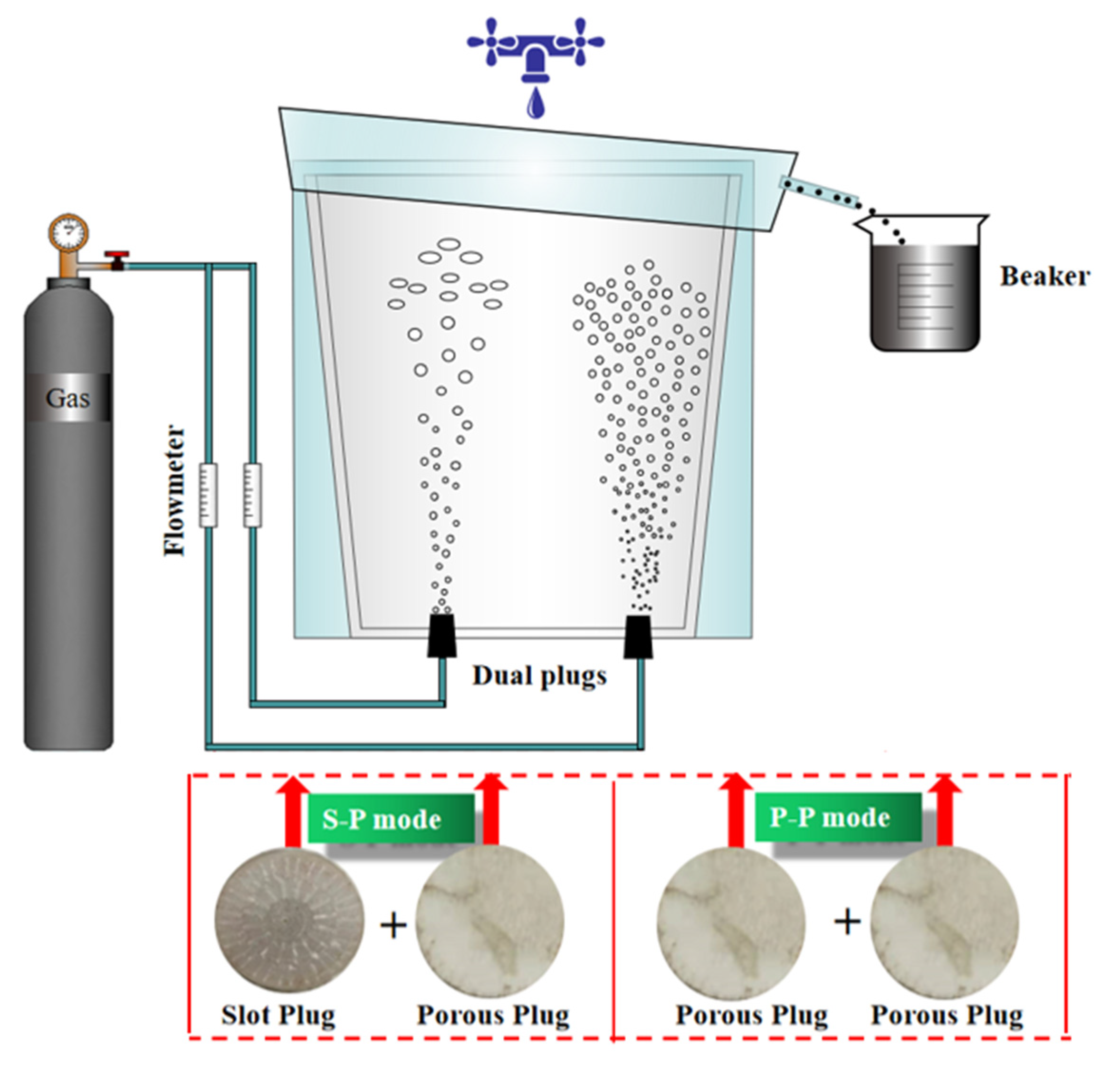
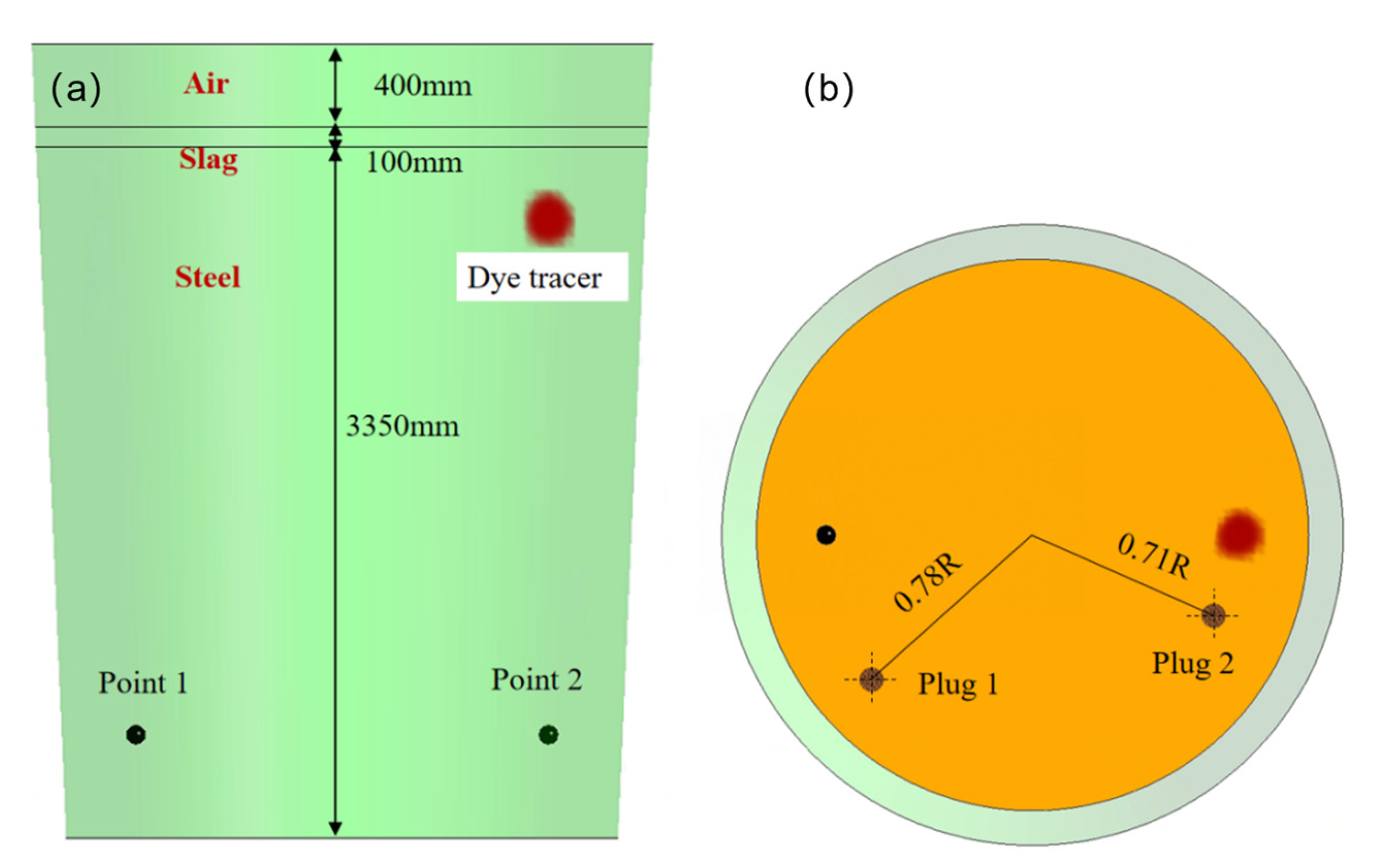
2.3. Boundary Condition and Numerical Details

In this work, the liquid dioctyl phthalate was substituted for inclusions to simulate the aggregation, breakage and flotation behavior during ladle refining. Based on the similarity principle, a 1:7 scale experimental model was used to visualize the flow-related phenomena in a ladle, just as shown in Figure 1. The system was composed of a water model, tuyeres, a gas pipe and an air compressor. The gas was injected from the bottom of the ladle with an air compressor at a pressure of 0.4 MPa. The initial volume of dioctyl phthalate was 60 mL. During ladle refining, the inclusions float to the slag layer, react with the slag and vanish after reaction. However, this reaction cannot be simulated in a water model. So, in order to solve this problem, we performed the reaction process as follows: a water tap was mounted above the model and constantly supplied fluid water at a fixed flow rate. Then, the liquid dioctyl phthalate near the free surface was pushed by the overflow and allocated into the beaker through a thin plastic channel. With this system, we can know the volume of inclusions flowing into the container at any given minute by reading the label carved on the surface of the beaker. Two kinds of tuyere matches were investigated: The first one was composed of one slot and one porous tuyere (S–P mode); The second one was composed of two porous slags (P–P mode). We monitored the inclusions every 1 min, and the total time was 10 min. The percentage of inclusion removement within every minute can be obtained using this model.
Figure 2 shows the computational domain with two tuyeres inserted at the bottom of the 1:1 scale practical ladle. One tuyere was located on the 0.78 radius of the ladle bottom, and the other one was located on the 0.71 radius of the bottom. The angle between the two tuyeres was 114°. The free surface of the steel was 400 mm from the top surface of the ladle, and the slag layer thickness was 100 mm. What is more, in order to investigate mixing behavior with different matches, we monitored two typical points distributed symmetrically along the left and right sides of the ladle, named Point 1 and Point 2. The mixing time was defined as the time when the concentration difference between the two points was less than 5%. The dye tracer was fed above Point 2, near the slag–metal interface.
Many previous works [24] have modeled the dynamic characteristics of bubble collision, aggregation and breakup, and have validated mathematical models through water model experiments. It is widely believed that bubble size changes have important effects on momentum exchange, steel mixing, and chemical reactions. For example, as a bubble rises, with the decreasing of ambient pressure, it would expand, resulting in a decrease in density and an increase in velocity. However, until now, few works have been carried out to explore this phenomenon and its effect on the inclusion and momentum exchange. Therefore, it is quite necessary and essential to investigate the complex bubbly-driven flow inside the ladle tube.
Considering the bubble expansion, the volume at different heights can be written as:
ρ p = P 0 + ρ m g H R g T ,
where H represents the height from the free surface to the bubble’s location. Through this equation, the expansion of bubbles can be solved.
The parameters used in this study are summarized in Table 1.

3. Results

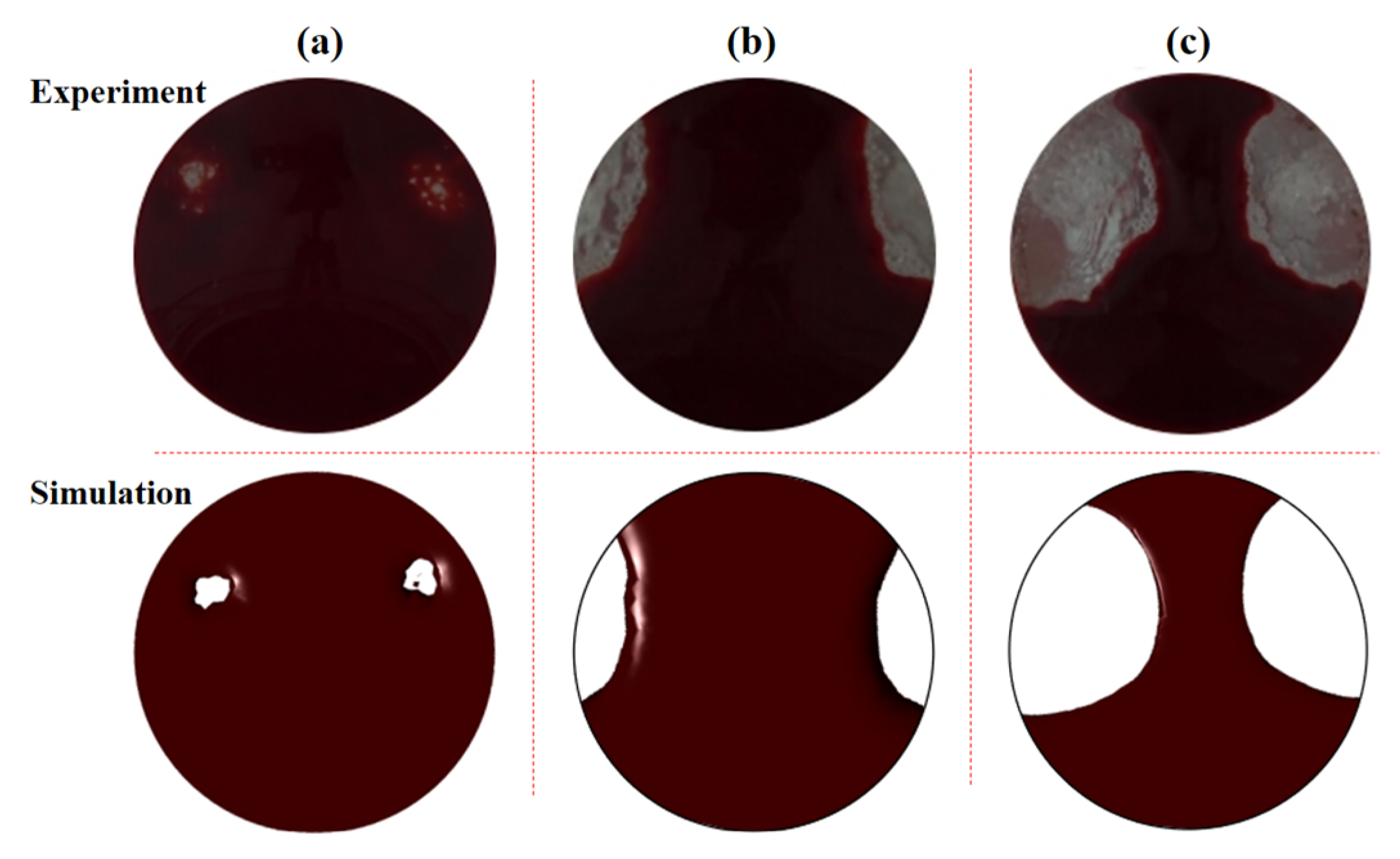
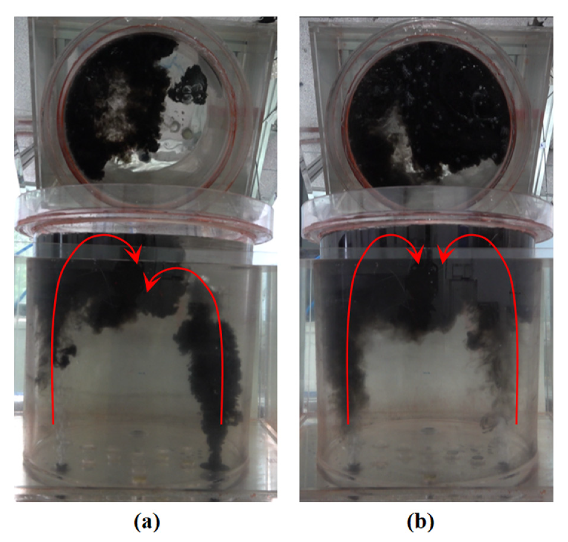
3.1. Validation for Mathematical Model

Based on the similarity principle, a 1:7 size water model experiment was set up and carried out to ratify the mathematical model. It ought to be noted that, to make comparisons with each other, the argon flow rate that is illustrated in the water model is penned as the value in the practical ladle. Gas flow rate is calculable through the similarity principle, and the result is shown in Table 1 above. It is visible from Figure 3a that, while the argon flow rate is depressed at 30 + 30 NL/min, the open eyes are pretty small and do not make contact with the ladle wall. However, after increasing to 90 + 90 NL/min, the open eyes are often larger and start to contact the wall, diminishing the ladle’s service life because of refractory erosion. When the flow rate continues to grow, the open eyes’ region becomes larger and larger. The simulation results are fairly similar to the experimental results, indicating that the mathematical model in this work is reliable.
Figure 4 illustrates the inclusion removal with different tuyere combinations. The percentage of inclusion removal was obtained by calculating it as the average value of the experiments repeated three times. After replacing one of the porous tuyeres with a slot tuyere, the inclusion removal rate rose significantly. The reason for this phenomenon is that more small-scale bubbles were generated to attach to the inclusions to float up and prevent the gas blown out by the slot tuyere from driving the steel to continue to move down. Furthermore, when the two tuyeres are all substituted by porous tuyeres (P-P mode), the removal rate of inclusions is marginally reduced. This implies that the utilization of porous tuyeres exhibits a considerable impact on inclusion removal.

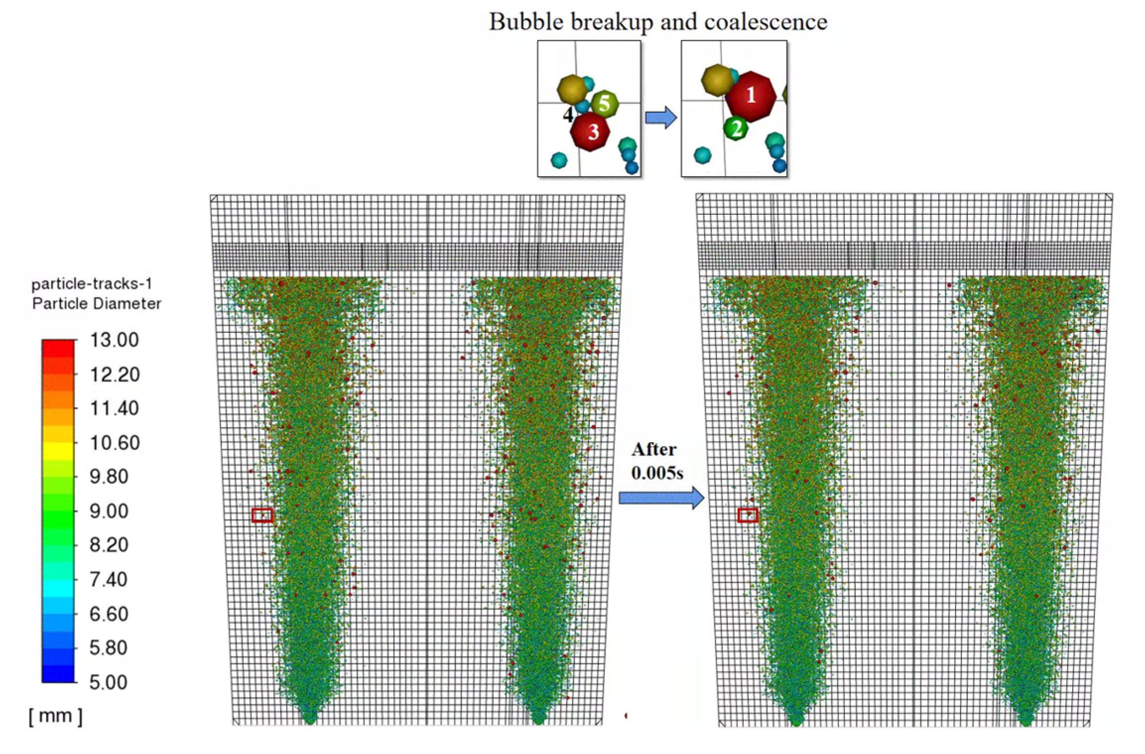
3.2. Coalescence and Breakup of Bubbles and Attachment of Inclusions

Figure 5 displays the breakup and coalescence of bubbles in steel. At the start, three bubbles marked 3, 4 and 5 get together, and after 0.005 s, they grow up to a bigger one (marked 1). In addition, a smaller one (marked 2) is also formed from parent bubble 3 during breakup process. Due to the decrease of hydraulic pressure, the bubbles expand when rising to the top, leading to the phenomenon where the bubbles near the top are larger than those near the bottom, and the plume zone is then presented as a V-like shape since the bubbles involve the surrounding liquid, forming a circulation inside the ladle. All these phenomena are vividly unveiled by means of this model.

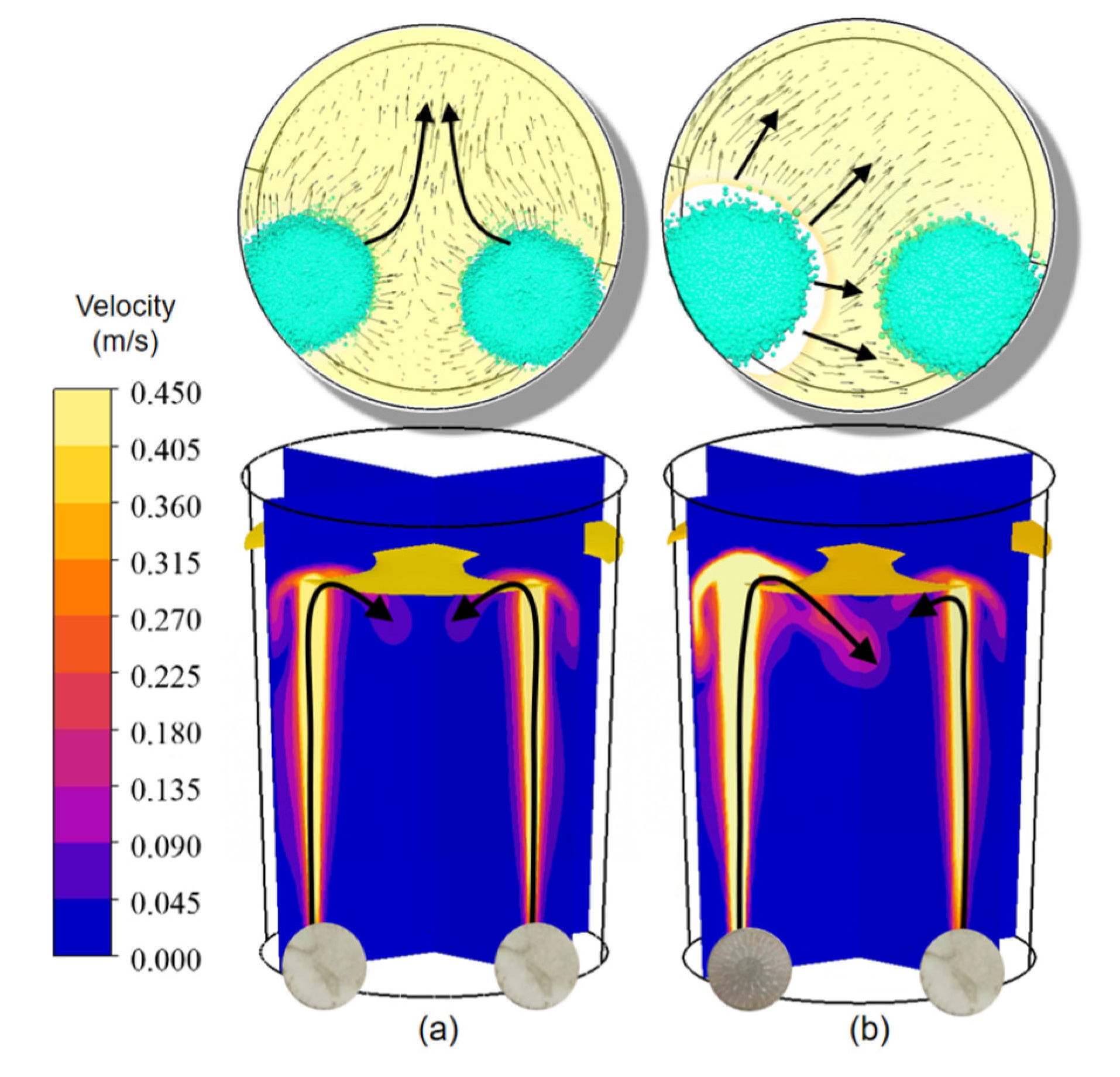
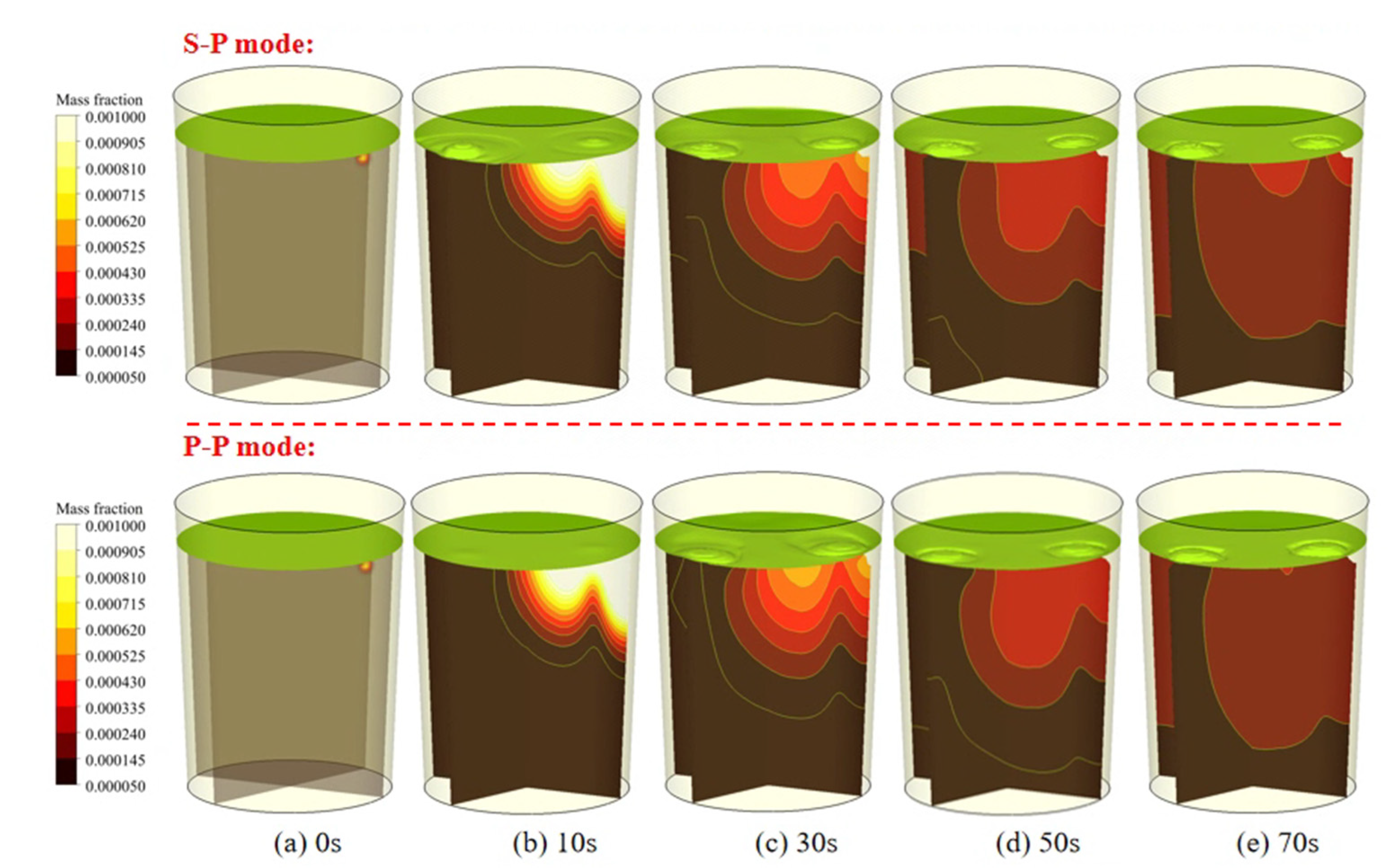
3.3. Effect of Tuyere Matches on the Flow Field and Inclusion Transport

Different from previous works, we proposed a new collection of tuyeres called slot–porous-matched dual tuyeres, and compared them with the traditional matches. Figure 6 illustrates the prediction of the flow field as well as slag eyes for different tuyere matches. The velocity vectors are plotted on the slag-metal interface in order to show the direction of flow path. According to Figure 6a, the flow field in the conventional P–P mode is almost symmetrical and uniform, while after using the S–P mode, the flow field becomes asymmetrical and uniform, just as displayed in Figure 6b. This implies that the S–P mode significantly changed the flow field in the ladle. As bubble size along the slot tuyere is larger than that on the porous tuyere side, the velocity along the slot tuyere side is also much larger than on the porous side, pushing more steel to move towards the porous tuyere side, just as revealed by the streamlines on the slag–metal interface. A similar phenomenon is also found in the water model experiment, which shows the morphology of the flow field through dye tracer injections, as shown in Figure 7.

3.4. Diameter and Density Distribution of Bubbles

Figure 8 reveals the averaged velocity on the axis of the plume zones. It can be seen from Figure 8a that the velocity in the S–P mode is obviously asymmetrical, as shown in Figure 8b and the water model experiments (Figure 7). However, in the P–P mode, the velocity on both sides is quite uniform, not too much different after all, because the bubble diameters are rather small and uniform.
Apart from the results above, the mixing behavior is also obtained, as shown in Figure 9. The initial positions of the melt alloy and the monitor points are displayed in Figure 2. The mixing time is defined as the time when the final mass fraction’s differences are within ±5%. Figure 9 shows that the injection mode has influenced the mixing behavior greatly in the ladle—the mixing times for the S–P and P–P modes are 109.95 s and 135.3 s, respectively. This indicates that the employment of the S–P mode may shorten the mixing time considerably in a real ladle. The reason for this phenomenon is because the recirculation flow near the ladle’s bottom is escalated.
Figure 10 illustrates the transient distribution of dye tracers. Comparisons were made between different tuyere matches. It is easy to see that the mixing speed is more uniform through the S–P mode than through the P–P mode. Additionally, the dead zone is significantly reduced, especially near the slot tuyere because it produces a stronger blowing effect for steel. For the P–P mode, as the stirring energy is low on both sides, the diffusion of dye tracers is quite slow. All in all, the optimal tuyere match is the S–P mode.
Figure 11 shows the transient percentage of inclusion removals in a ladle. The total monitoring time is 560 s. It can be seen from Figure 11 that the percentage of inclusion removal through the S–P mode is 36.34%. When it comes to P–P mode, the inclusion ratio first increases fast, then the growing speed decreases after 191.15 s, finally reaching 34.14%. The same trend is also found in the water model experiment (Figure 4). So, by comparing the two tuyere modes, we can come to the conclusion that the S–P mode is optimal for removing inclusions in steel. This is because the S–P mode increases the turbulence of the liquid near the bottom of the ladle and prevents the inclusions recycling downwards with the steel.

4. Conclusions

The main innovation of this work was to propose a new injection mode through a new mathematical model, which was validated through the water model result. This model is used to describe the aggregation and breakup of two different discrete phases, considering density variation as well as bubble expansion. The following conclusions can be drawn:
(1)
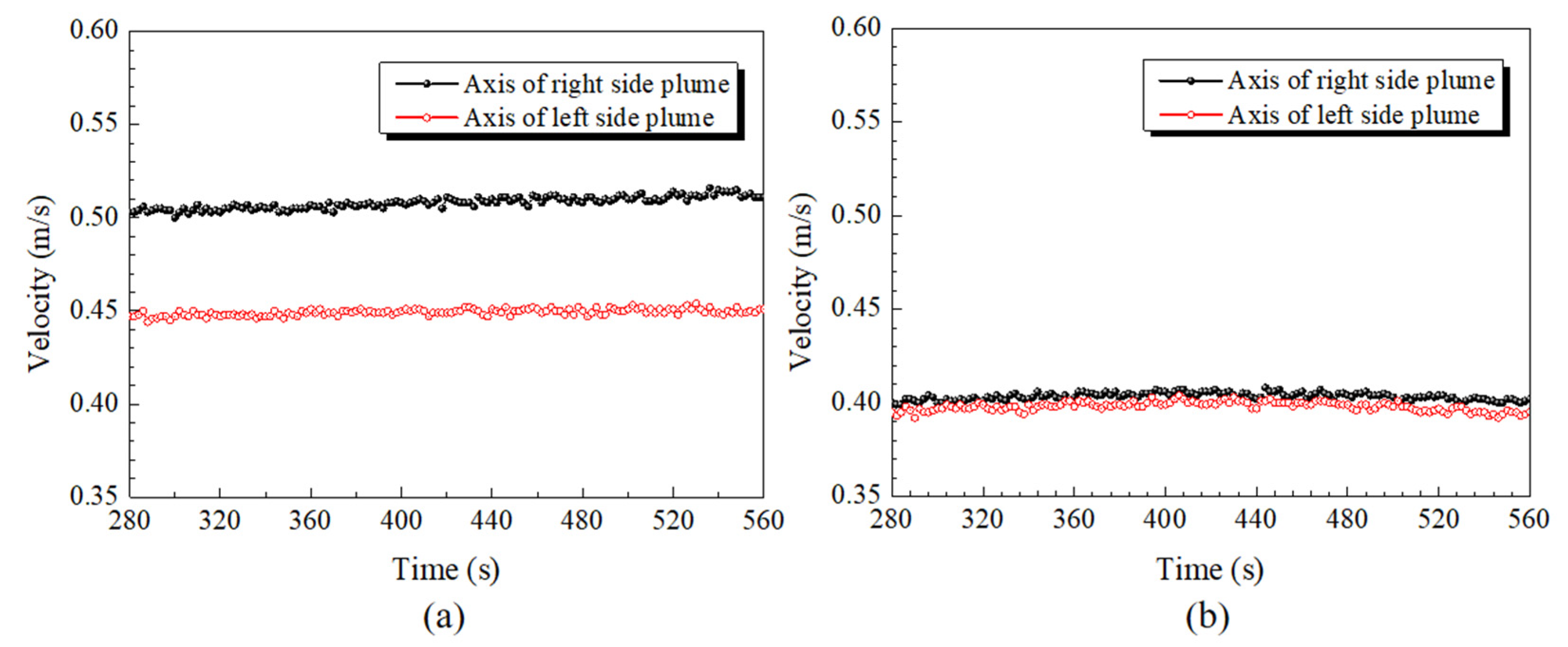
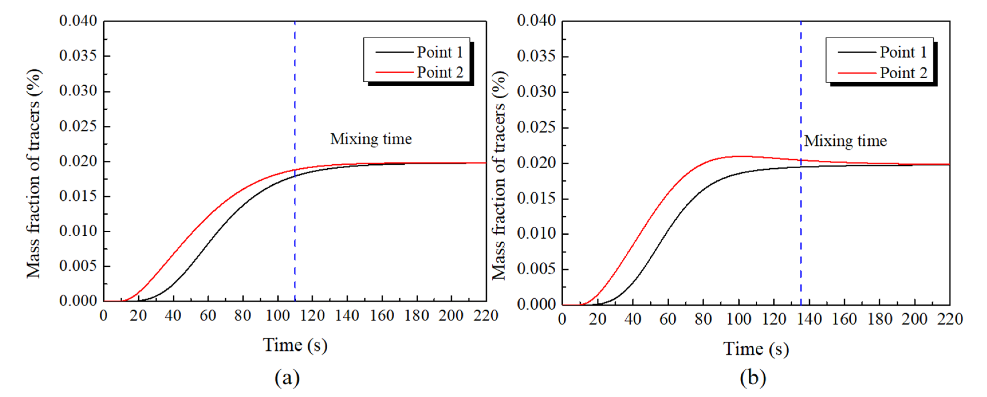
The flow field under S–P mode is quite asymmetrical due to the differences of bubbles in size, which is beneficial for shortening mixing time during ladle refining;
(2)
Due to the decrease of hydraulic pressure, bubbles would expand when rising to the top. This is why the velocity near the top is higher;
(3)
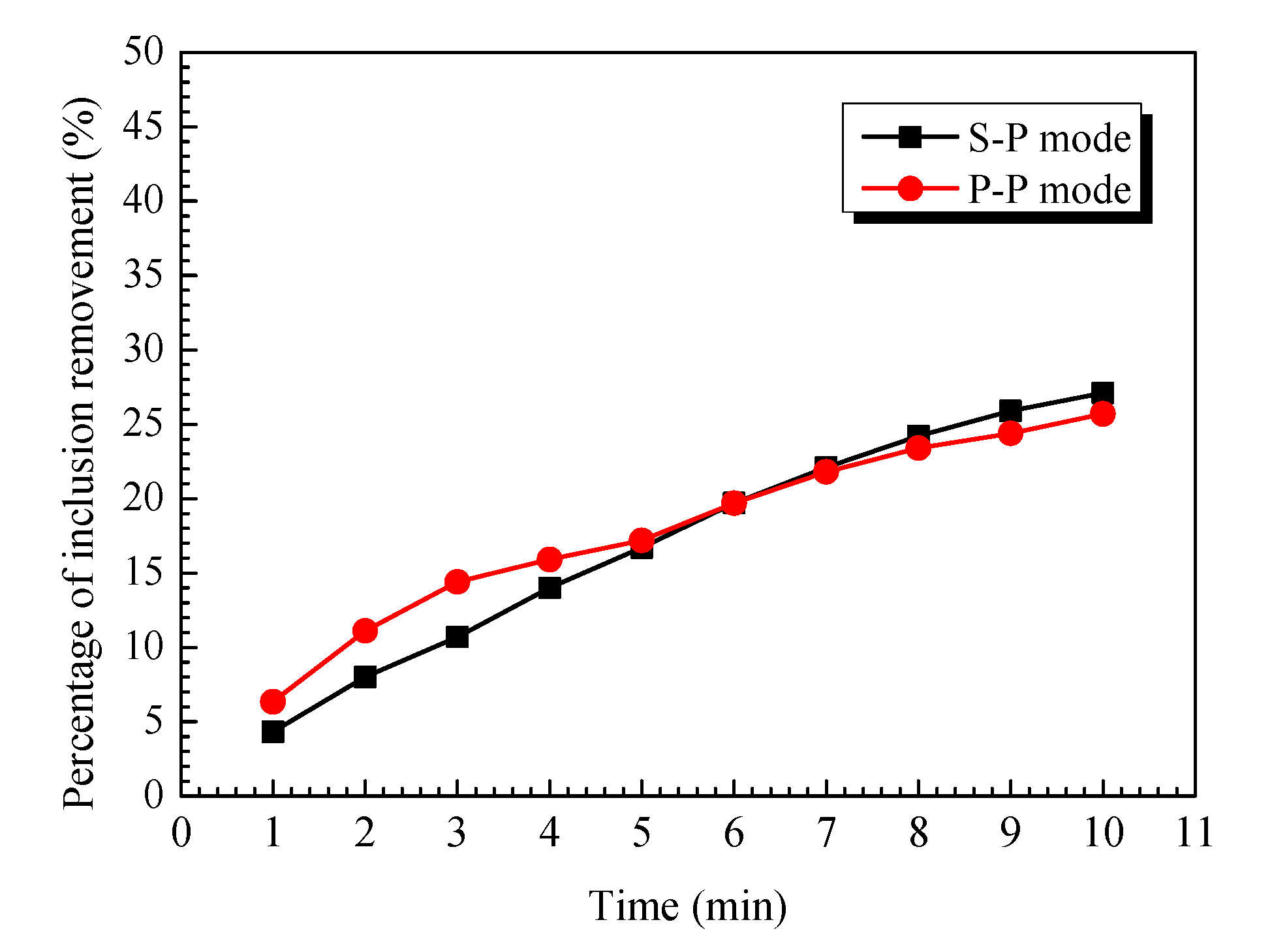
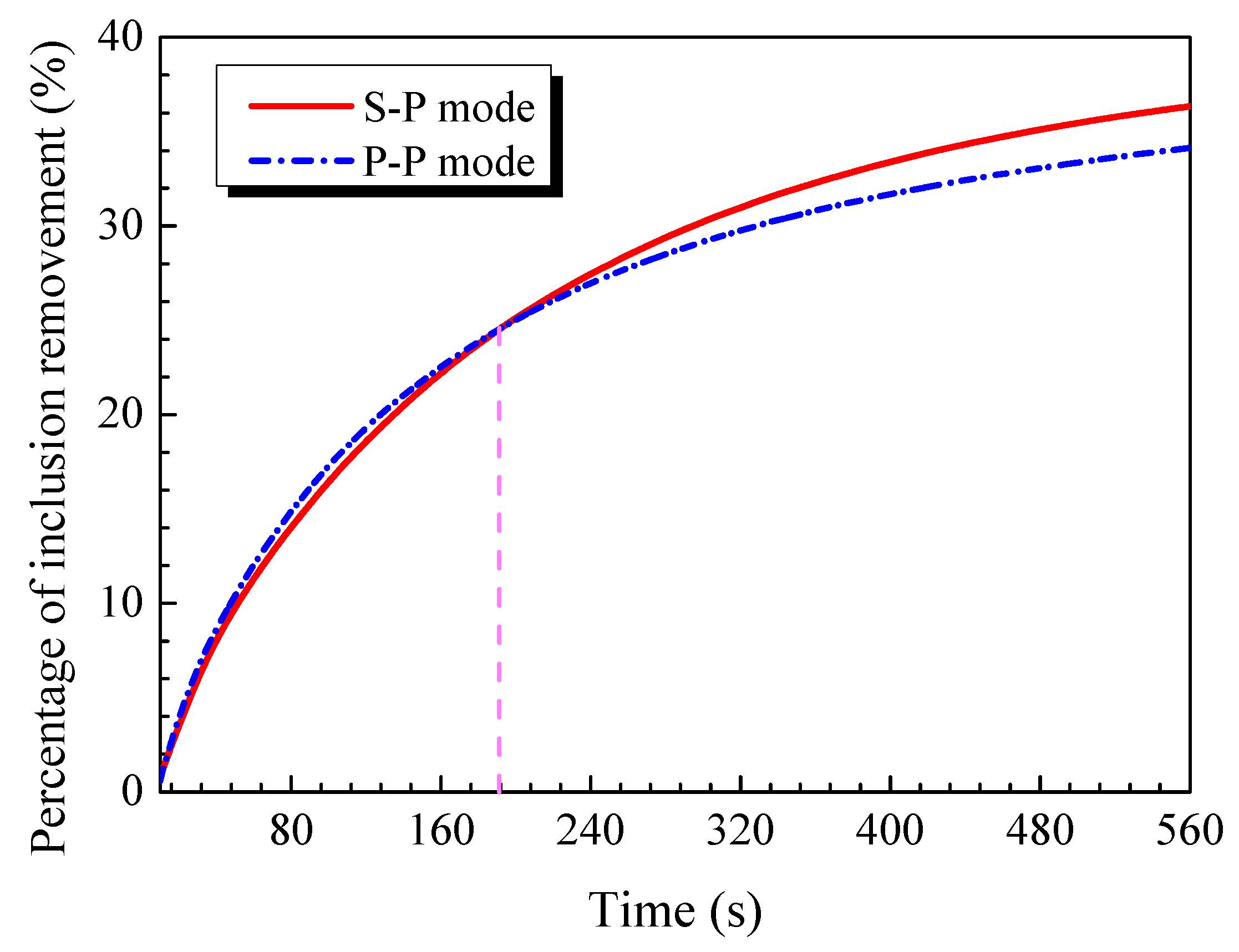
The slot–porous matched dual tuyeres can significantly increase the inclusion removal ratio and shorten the mixing time at the same time. Therefore, this type of injection argon is recommended for use in future refining.

Author Contributions

Conceptualization, H.W. and J.T.; methodology, D.W.; software, T.Q.; validation, D.H. and S.H.; investigation, G.W.; writing—original draft preparation, X.L. All authors have read and agreed to the published version of the manuscript.

Funding

This work was financially supported by the National Natural Science Foundation of China (No. 52204348, No. 52274339, No. 52174321, No. 52074186), Natural Science Foundation of Jiangsu Province: BK20200869 and the Natural Science Foundation of Jiangsu Higher Education Institutions of China (No. 22KJB450002).

Institutional Review Board Statement

Not applicable.

Informed Consent Statement

Not applicable.

Data Availability Statement

Not applicable.

Conflicts of Interest

The authors declare no conflict of interest.

References

  1. Lobanov, S.P.; Ovsyannikov, V.G.; Voronov, G.A.; Sarychev, A.V. Bottom blowing tuyeres for 175-ton steel ladles in service at an open-hearth furnace shop (MISW JSC). Refract. Ind. Ceram. 2005, 46, 85–86. [Google Scholar] [CrossRef]
  2. Krishna, R.; Baten, J.M. CFD Simulations of Wall Mass Transfer for Taylor Flow in Circular Capillaries. Chem. Eng. Res. Des. 2001, 79, 283–309. [Google Scholar] [CrossRef]
  3. Geng, D.Q.; Lei, H.; He, J.C. Effect of Electromagnetic Swirling Flow in Slide-gate SEN on Flow Field in Square Billet Continuous Casting Mold. ISIJ Int. 2010, 50, 1597–1605. [Google Scholar] [CrossRef] [Green Version]
  4. Hibiki, T.; Ishii, M. Development of One-group Interfacial Area Transport Equation in Bubbly Flow Systems. Int. J. Heat Mass Transf. 2002, 45, 2351–2372. [Google Scholar] [CrossRef]
  5. Kitagawa, A.; Sugiyama, K.; Murai, Y. Experimental Detection of Bubble-bubble Interactions in a Wall-sliding Bubble Swarm. Int. J. Multiph. Flow 2004, 30, 1213–1234. [Google Scholar] [CrossRef]
  6. Xiao, Z.Y.; Tan, R.B.H. A Model for Bubble-Bubble and Bubble-Wall Interaction in Bubble Formation. AIChE J. 2006, 52, 86–98. [Google Scholar] [CrossRef]
  7. Sanyal, J.; Marchisio, D.L.; Fox, O.; Dhanasekharan, K. On the Comparison between Population Balance Models for CFD Simulation of Bubble Columns. Ind. Eng. Chem. Res. 2005, 44, 5063–5072. [Google Scholar] [CrossRef] [Green Version]
  8. Lou, W.T.; Zhu, M.Y. Numerical Simulations of Inclusion Behavior and Mixing Phenomena in Gas-stirred Ladles with Different Arrangement of Tuyeres. ISIJ Int. 2014, 54, 9–18. [Google Scholar] [CrossRef] [Green Version]
  9. Wang, L.T.; Peng, S.H.; Zhang, Q.Y.; Li, Z.B. Mathematical Model for Growth and Removal of Inclusion in a Multi-tuyere Ladle during Gas-stirring. Steel Res. Int. 2006, 77, 25–31. [Google Scholar] [CrossRef]
  10. Sha, Z.; Laari, A.; Turunen, I. Multi-Phase-Multi-Size Group Model for the Inclusion of Population Balances into the CFD Simulation of Gas-Liquid Bubbly Flows. Chem. Eng. Technol. 2006, 29, 550–559. [Google Scholar] [CrossRef]
  11. Thomas, B.G.; Yuan, Q.; Mahmood, S.; Liu, R.; Chaudhary, R. Transport and Entrapment of Particles in Steel Continuous Casting. Metall. Mater. Trans. B 2014, 45, 22–35. [Google Scholar] [CrossRef]
  12. Liu, Z.Q.; Li, L.M.; Li, B.K.; Jiang, M.F. Large Eddy Simulation of Transient Flow, Solidification, and Particle Transport Processes in Continuous-Casting Mold. JOM 2014, 66, 1184–1196. [Google Scholar] [CrossRef]
  13. Yin, Y.B.; Zhang, J.M.; Dong, Q.P.; Li, Y.Y. Modelling on Inclusion Motion and Entrapment during the Full Solidification in Curved Billet Caster. Metals 2018, 8, 320. [Google Scholar] [CrossRef] [Green Version]
  14. Lei, H.; Geng, D.Q.; He, J.C. A Continuum Model of Solidification and Inclusion Collision-growth in the Slab Continuous Casting Caster. ISIJ Int. 2009, 49, 1575–1582. [Google Scholar] [CrossRef] [Green Version]
  15. Colella, D.; Vinci, D.; Bagatin, R.; Masi, M.; Bakr, E.A. A Study on Coalescence and Breakage Mechanisms in Three Different Bubble Columns. Chem. Eng. Sci. 1999, 54, 4767–4777. [Google Scholar] [CrossRef]
  16. Olmos, E.; Gentric, C.; Vial, C.; Wild, G.; Midoux, N. Numerical Simulation of Multiphase Flow in Bubble Column Reactors: Influence of Bubble Coalescence and Break-up. Chem. Eng. Sci. 2001, 56, 6359–6365. [Google Scholar] [CrossRef]
  17. Liu, W.J.; Lee, J.; Guo, X.P.; Silaen, A.K.; Zhou, C.Q. Argon Bubble Coalescence and Breakup in a Steel Ladle with Bottom Plugs. ISIJ Int. 2018, 90, 1800396. [Google Scholar] [CrossRef]
  18. Liu, Z.Q.; Li, B.K.; Xiao, L.J.; Gan, Y. Physical and Numerical Simulation of Mixed Columnar-equiaxed Solidification during Cold Strip Feeding in Continuous Casting. Acta Metall. Sin. 2022, 58, 1236–1252. [Google Scholar] [CrossRef]
  19. Wu, Y.D.; Liu, Z.Q.; Fang, W.; Li, B.K.; Gan, Y. Experimental investigation of trajectories, velocities and size distributions of bubbles in a continuous-casting mold. Powder Technol. 2021, 387, 325–335. [Google Scholar] [CrossRef]
  20. Li, X.L.; Li, B.K.; Liu, Z.Q.; Wang, D.Y.; Qu, T.P.; Hu, S.Y.; Wang, C.J.; Gao, R.Z. Evaluation of Slag Entrapment in Continuous Casting Mold Based on the LES-VOF-DPM Coupled Model. Metall. Mater. Trans. B 2021, 52, 3246–3264. [Google Scholar] [CrossRef]
  21. Li, X.L.; Li, B.K.; Liu, Z.Q.; Niu, R.; Liu, Q.; Huang, X.C. Detection and Numerical Simulation of Non-Metallic Inclusions in Continuous Casting Slab. Steel Res. Int. 2019, 90, 1800423. [Google Scholar] [CrossRef]
  22. Li, L.M.; Liu, Z.Q.; Li, B.K. Modelling of Bubble Aggregation, Breakage and Transport in Slab Continuous Casting Mold. J. Iron Steel Res. Int. 2015, 22, 30–35. [Google Scholar] [CrossRef]
  23. Li, Q.; Cheng, J.C.; Yang, C.; Mao, Z.S. Simulation of a Bubble Column by Computational Fluid Dynamics and Population Balance Equation using the Cell Average Method. Chem. Eng. Technol. 2017, 40, 1792–1801. [Google Scholar] [CrossRef]
  24. Chen, S.F.; Lei, H.; Hou, H.C.; Ding, C.Y.; Zhang, H.; Zhao, Y. Collision-coalescence among Inclusions with Bubble Attachment and Transport in Molten Steel of RH. J. Mater. Res. Technol. 2021, 15, 5141–5150. [Google Scholar] [CrossRef]
Figure 1. Configuration of water model experiment.
Metals 13 00667 g001
Figure 2. Geometry and boundary conditions for the full size model: (a) isometric view, (b) top view.
Metals 13 00667 g002
Figure 3. Comparison of open eyes at different flow rates: (a) 30 NL/min, (b) 90 NL/min, (c) 150 NL/min.
Metals 13 00667 g003
Figure 4. Effect of argon-blow modes on inclusion removal through the water model experiment.
Metals 13 00667 g004
Figure 5. Bubbles coalescence and breakup.
Metals 13 00667 g005
Figure 6. Velocity distribution in liquid steel and slag–metal interface: (a) P–P mode, (b) S–P mode.
Metals 13 00667 g006
Figure 7. Comparison of flow stream at different argon-flow modes: (a) S–P mode, (b) P–P mode.
Metals 13 00667 g007
Figure 8. Comparison of velocity on the axis of plume zones: (a) S–P mode, (b) P–P mode.
Metals 13 00667 g008
Figure 9. Comparison of mixing time during ladle refining: (a) S–P mode, (b) P–P mode.
Metals 13 00667 g009
Figure 10. Mass fraction of dye tracers at different times with different modes: (a) 0 s, (b) 10 s, (c) 30 s, (d) 50 s, (e) 70 s.
Metals 13 00667 g010
Figure 11. Percentage of inclusion removal at different modes.
Metals 13 00667 g011
Table 1. Geometry and material properties.
ParametersReal LadleWater Model (Scale 1:7)
Gas flow rate, NL/min150 + 1500.765 + 0.765
tuyere angle °114°114°
Dynamic viscosity of steel, kg/(m·s)0.00510.001
Dynamic viscosity of air, kg/(m·s)1.79 × 10−51.79 × 10−5
Density of dioctyl phthalate, kg/(m3)2800900
Radius of ladle bottom, mm2717388
Disclaimer/Publisher’s Note: The statements, opinions and data contained in all publications are solely those of the individual author(s) and contributor(s) and not of MDPI and/or the editor(s). MDPI and/or the editor(s) disclaim responsibility for any injury to people or property resulting from any ideas, methods, instructions or products referred to in the content.

