
Analysis of Uneven Wear Mechanism of Narrow-Face Copper Wall of Funnel Mold
1
College of Metallurgy and Energy, North China University of Science and Technology, Tangshan 063000, China
2
College of Materials Science and Engineering, Hebei University of Science and Technology, Shijiazhuang 050018, China
3
Shougang Qian’an Iron & Steel Company, Qian’an 064400, China
*
Author to whom correspondence should be addressed.
Metals 2023, 13(4), 666; https://doi.org/10.3390/met13040666
Submission received: 26 January 2023
/
Revised: 20 February 2023
/
Accepted: 22 February 2023
/
Published: 28 March 2023
(This article belongs to the Special Issue Advanced Tundish Metallurgy and Clean Steel Technology)
Abstract
:In thin-slab continuous casting, due to the influence of the special shape of the funnel mold, cracks at the corner of the slab shell are more likely to occur than those in conventional slab shells, and a serious wear phenomenon also appears on the narrow face of the copper wall of the mold. Aimed at the corner cracks of thin slabs and the wear phenomenon of the copper wall, a new 3D stress analysis model in a funnel mold has been developed to simulate the stress-–train behavior of the slab shell under high-speed continuous casting. The results show that at the position 600 mm below the meniscus, the gap begins to appear at the corner of the slab; the maximum value of the first principal stress appears at the corner. The shell is squeezed by the copper wall during the downward movement in the funnel mold, and the slab shell in the funnel area moves towards the narrow face. The displacement causes the deformation of the slab shell to extend to the corners, the deformed shell is pressed against the corner of the copper wall. A new type of copper wall was designed for production, and it was found that the cracks at the corner of the slab shell were greatly reduced.
1. Introduction
The process of continuous casting and rolling of thin slabs is one of the most important technological advances in the steel production industry in recent years. With the advantages of short process, high production efficiency, and low energy consumption [1,2,3], it has become an important process for the production of hot-rolled sheets and strips in the metallurgical industry. For the purpose of near-net rolling, the thickness of the thin slab is thinner. In order to ensure sufficient working space for the submerged entry nozzle, a funnel-shaped area is set in the upper center of the mold, which is completely different from that of the traditional slab mold, resulting in the unique complex inner cavity structure of the thin-slab mold [4]. The funnel mold has a complex structure, the curvature of the funnel area decreases from top to bottom, and the shell in the funnel area will be squeezed by the copper wall, resulting in a more complex stress state of the shell in the mold. In actual production, it was found that the crack rate of the corner of the slab shell increased significantly, and the corresponding hot-rolled steel wall also had a large number of rotten edge defects. At the same time, serious wear phenomenon also appeared on the surface of the copper wall on the narrow face of the mold. The analysis of the solidification, stress, and deformation behavior of the shell can reveal the reasons for the generation of cracks and copper wear, which have very important scientific value and application significance for the efficient production of high-quality thin slabs.
Over the years, a variety of mathematical models have been developed for thermal–mechanical coupling analysis of the stress–strain behavior of molds and slabs. AIda Ramacciott et al. [5] established a stress model based on the assumption of basic deformation theory, added a gap factor to simulate the solidification process of the funnel mold, and analyzed the stress state of each point of the shell. In terms of 3D models, O’Connor et al. [6] established a 3D mathematical model of the thermal state in the mold of a thin-slab caster by taking von Mises yield criterion and Prandtl–Reuss flow rule into consideration, analyzed the heat transfer of the slab and mold stress, and reproduced the area of the mold prone to cracking due to the thermal cycle. Har et al. [7] used the differential method and finite element method to establish a heat transfer model, as well as elastic–plastic and creep models, and coupled analysis of the heat transfer and stress behavior during the solidification process of slab continuous casting. The team of Vakhrushev [8] established a viscoplastic three-dimensional stress model of a thin slab and analyzed the influence of the strain rate sensitivity parameter on the viscoplastic effective viscosity. Professor Zhu Miaoyong’s team [9], in a representative work, applied the heat flow of the shell onto the inner surface of the copper wall and conducted a three-dimensional stress field study specifically for the copper wall.
For details such as corner defects of thin slabs and uneven wear of copper walls under the dual action of high-speed drawing and funnel extrusion, the existing research is still insufficient. Since the shape of the mold and shell changes continuously from top to bottom, it is difficult for traditional models to accurately reveal its stress–strain process, and a new algorithm needs to be developed.
Aiming at the problem of cracks at the corners of the thin slab and wear of the copper wall on the narrow face of the mold, this study established a stress model of the slab and the copper wall by using a contact algorithm based on the three-dimensional temperature field. The three-dimensional slab stress field distribution of the flexible thin-slab casting (FTSC) continuous casting mold is analyzed, which can provide a reference for analyzing the cracks of thin slab corners and mold wear.
2. The Establishment of the Model
2.1. Assumption of the Model
The stress deformation process of a thin-slab shell in a funnel mold is very complicated and can not be described accurately by a mathematical method directly. Based on the characteristics of the stress state and deformation characteristics of the slab, and referring to the research experience of previous work [10,11,12,13], the deformation behavior of the thin slab funnel mold is appropriately simplified and assumed:
- The continuous casting process is in a stable state;
- The circulating effect of mold vibration on the surface of the shell is ignored;
- The solidified shell is an elastic–plastic material, and the deformation of the shell meets the requirements of large elastic–plastic deformation;
- The plastic deformation of the high-temperature solid shell obeys the Von Mises yield criterion;
- The copper wall of the mold is a rigid body, ignoring the deformation caused by temperature change and mechanical action;
- Neglecting the influence of dendrites and segregation in the slab, the mechanical properties of the solidified slab are isotropic.
2.2. Mathematical Model of Slab Stress
When the steel enters the plastic state, there is no one-to-one correspondence between the stress and strain. The strain not only depends on the current stress state, but also depends on the entire loading history. At this time it is impossible to establish the full relationship between the final stress and the strain, and the incremental theory must be adopted to establish the incremental relationship between the stress and strain reflecting the loading history [14,15,16].
- (1)
- Basic relationship between thermoelastic–plastic stress and strain. For elastic models, strain increments are expressed as
[D]e is the elastic matrix.
where E is the modulus of elasticity; u is the Poisson’s ratio; d represents the increment; and the subscripts e, p, and T in the equation below represent elasticity, plasticity, and heat transfer, respectively.
The total strain in the thermoelastoplastic model consists of elastic strain, plastic strain, and thermal strain expressed as
In the thermoplastic model, the increments in stress and elastic strain still conform to the expression, so substituting the formula to obtain the relationship between stress and total strain yields the following:
To perform a stress analysis, stress and total strain are written as follows:
where [D]ep is the elastoplastic matrix of the thermoelastoplastic model.
- (2)
- Solution for [D]ep
The solution for [D]ep involves the yield, strain strengthening, and flow criteria of the material. A specific combination of the three describes a unique plastic behavior.
where the expression for the plastic modulus matrix is as follows:
where is the equivalent plastic modulus of the material. , which is related to the elastic modulus and tangent modulus , is ; the tangent modulus is determined by the experimentally tested curve, .
The elastoplastic modulus matrix is defined. In the stress field calculation, the initial stress of the just-solidified shell is 0, the initial solidified shell is in close contact with the copper wall, and the symmetrical displacement boundary condition is applied on the symmetrical surface of the slab. A downward displacement of the slab model is applied to the upper surface of the solid slab model, the rigid surface of the copper wall constrains the surface of the slab to ensure that the stressed slab shell does not penetrate the copper wall, and the hydrostatic pressure of the molten steel is applied on the node at the position of the solidification front:
In the equation, ρ is the density of molten steel, which is 7200 kg/m3, and h is the distance between the molten steel and the meniscus, m. Because only the casting slab strain in the mold is calculated, the range of h is 0~1.12 m
2.3. Finite Element Model of Slab Stress
In view of the structural characteristics of the thin slab funnel mold, our research team established a three-dimensional heat transfer model of the thin slab copper wall and the continuous casting slab based on the three-dimensional nodal temperature inheritance idea (3D·NTI) and obtained the slab temperature field [17,18,19]. Based on the temperature field and the thermal–mechanical coupling model as the link, this research creates a three-dimensional slab stress model and analyzes the deformation behavior during the movement of the slab shell under the action of extrusion.
The three-dimensional stress finite element model established in this study consists of two parts: the finite element model of the casting slab and the rigid contact surface of the copper wall of the mold.
- (1)
- Finite element model of casting slab.
When establishing the 3D slab stress model, it is still based on the 3D slab heat transfer model. According to the 3D slab temperature field, the position where the initial shell of the slab is completely solidified is determined. At this time, the 3D slab solid model is reconstructed. Using the working plane, a slicing is performed at the position where the primary shell of the solid model of the three-dimensional casting slab is completely solidified. The work plane is moved down one element step distance for a second split. A solid model of the cast slab is obtained for stress analysis.
According to the grid format of the three-dimensional slab heat transfer finite element model, the solid model of the slab for stress analysis is meshed. The stress analysis model adopts the structural element SOLID185 element, with a total of 1405 elements.
- (2)
- The rigid contact surface of the copper wall of the mold.
According to the shape of the inner surface of the copper wall of the funnel mold, a completely rigid surface was established on the outer surface of the finite element model of the slab, which was used as the inner surface of the copper wall of the mold of the stress solid model. Using the contact function of ANSYS, the surface–surface contact between the slab and the copper wall was constructed.
The outer surface of the slab finite element model is set as a flexible surface, and a contact element is set on its surface element, and the contact element type is CONTA174 element. The rigid contact surface of the mold copper wall is a rigid surface, and the contact element type is TARGE170 element. The rigid contact surface can characterize the restraint and support effect of the mold copper wall on the casting slab and prevent the slab shell from intruding into the mold copper wall. When the casting mold is in contact with the copper wall and the two surfaces slide relative to each other, the dynamic friction coefficient is set to 0.1, as shown in Table 1 when the contact pair is set. Figure 1 shows the 3D stress finite element model in this study.
2.4. Analysis Method of Numerical Model
The team, based on 3D·NTI, has successfully established a three-dimensional heat transfer model of continuous casting of thin slabs and successfully simulated the heat transfer phenomenon of thin slabs in the mold. Based on the three-dimensional casting slab heat transfer model, the three-dimensional casting slab stress entity model and finite element model are established, and the stress analysis of the solidified slab shell in the mold is carried out.
First, a first stress analysis is performed. According to the nodal temperature distribution of the three-dimensional casting slab temperature field, the initial complete solidification position of the slab shell is determined, and the nodal temperature is imported into the coupled heat transfer model according to the nodal coordinates.
Secondly, according to the element temperature of the coupled heat transfer model, the elements in the coupled heat transfer model that are above the liquidus temperature are marked. The corresponding elements in the slab stress model are specified according to the element properties of the coupled temperature field marker. The area of solidified slab shell that can participate in deformation is determined by using the element life and death technique to allow the liquid element to hibernate.
Then, solid blanks with solid-phase fractions greater than 0.8 in the solid–liquid phase zone have strength, and we set the unit at this moment temperature as the solidification front. The solidification front is formed by the common nodes of the active element and the dormant element, and the static pressure of molten steel is applied to the solidification front node. At the same time, the calculation result of the coupled temperature field is applied to the stress model as a temperature load. Displacement constraints are applied on the symmetry plane of the stress finite element model, and downward displacement steps are applied on the upper surface of the model. The displacement step is the thickness of the single-layer mesh of the three-dimensional slab heat transfer model. The first numerical analysis of the stress field is performed.
Again, the second stress analysis is carried out. At this point, the slab model has been moved down a mesh thickness distance. The node temperature corresponding to the three-dimensional slab temperature field is imported into the coupled heat transfer model, and the elements above the liquidus temperature are re-marked according to the temperature results. The 3D stress model is reloaded and restarted on the basis of the first shell deformation to realize the continuous deformation of the shell. The shape of the shell is updated according to the re-marked elements of the coupled temperature field, and a new solidification front node is determined. At the solidification front of the shell, the static pressure of molten steel is applied, the temperature load is applied to the model node, and the shell is moved down again by one displacement step. The second stress calculation is performed.
Finally, the above steps are repeated until the casting slab moves to the outlet of the mold and the stress calculation is completed.
3. Production Parameters
4. Results and Discussion
4.1. Heat Transfer Analysis of Slab
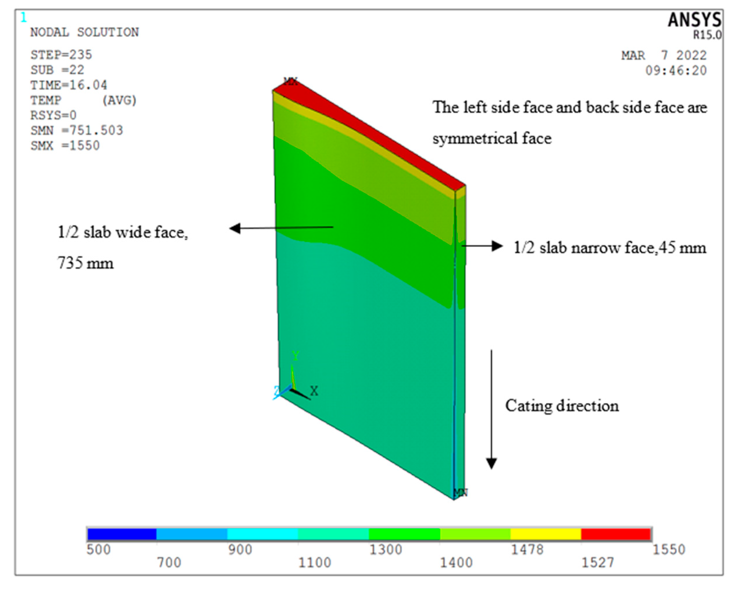
Under typical pouring conditions, using the established three-dimensional casting slab heat transfer analysis model of the thin-slab mold, the heat transfer behavior of the casting slab in the mold is analyzed, and the analysis results of the overall temperature field of the casting slab are shown in Figure 2.
From the results of the overall temperature field of the slab, it can be seen that the temperature of the molten steel surface of the mold is kept at the pouring temperature of 1550 °C.
From 10 mm below the molten steel level to the outlet of the mold, the central surface temperature of the wide face of the slab decreases from 1490 °C to 1188 °C, and the central surface temperature of the narrow face of the slab drops from 1489 °C to 1142 °C. Since there is a funnel-shaped inner cavity in the central area of the wide surface of the mold, the molten steel storage capacity in this area is the largest; at the same time, the width of the narrow surface is small, and the two-dimensional heat transfer conditions at the corners of the slab also have a certain influence on the heat dissipation of the entire narrow surface. Under the combined action of the two factors, the surface temperature of the slab at the center of the wide face decreases more slowly than that of the center of the narrow face. The two-dimensional heat transfer conditions in the corner area of the slab make the temperature decrease at the corner of the slab larger than that in the center of the wide surface and the center of the narrow surface. From the liquid level of the mold to the outlet of the mold, the corner temperature of the slab decreases from 1380 °C to 752 °C.
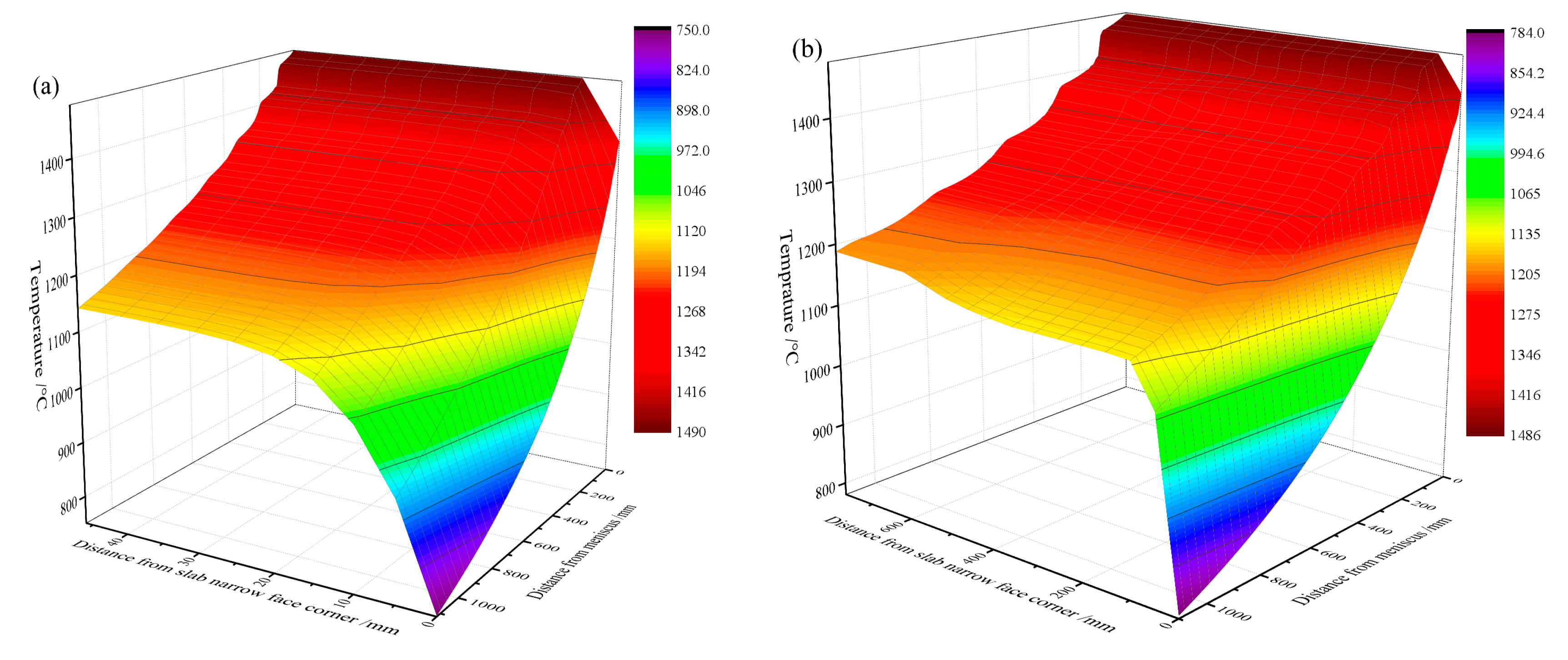
The surface temperature distributions at the center of the wide surface, the center of the narrow surface, and the corners of the thin slab are shown in Figure 3. It can be seen from the figure that from the meniscus of the mold to the outlet of the mold, the surface temperature of each typical position along the drawing direction shows a continuous downward trend. The decreasing trend of the temperature in the corner area of the slab is the most significant, and the decreasing trend of the surface temperature in the center of the wide face and the center of the narrow face is gentle.
4.2. Gap Distribution
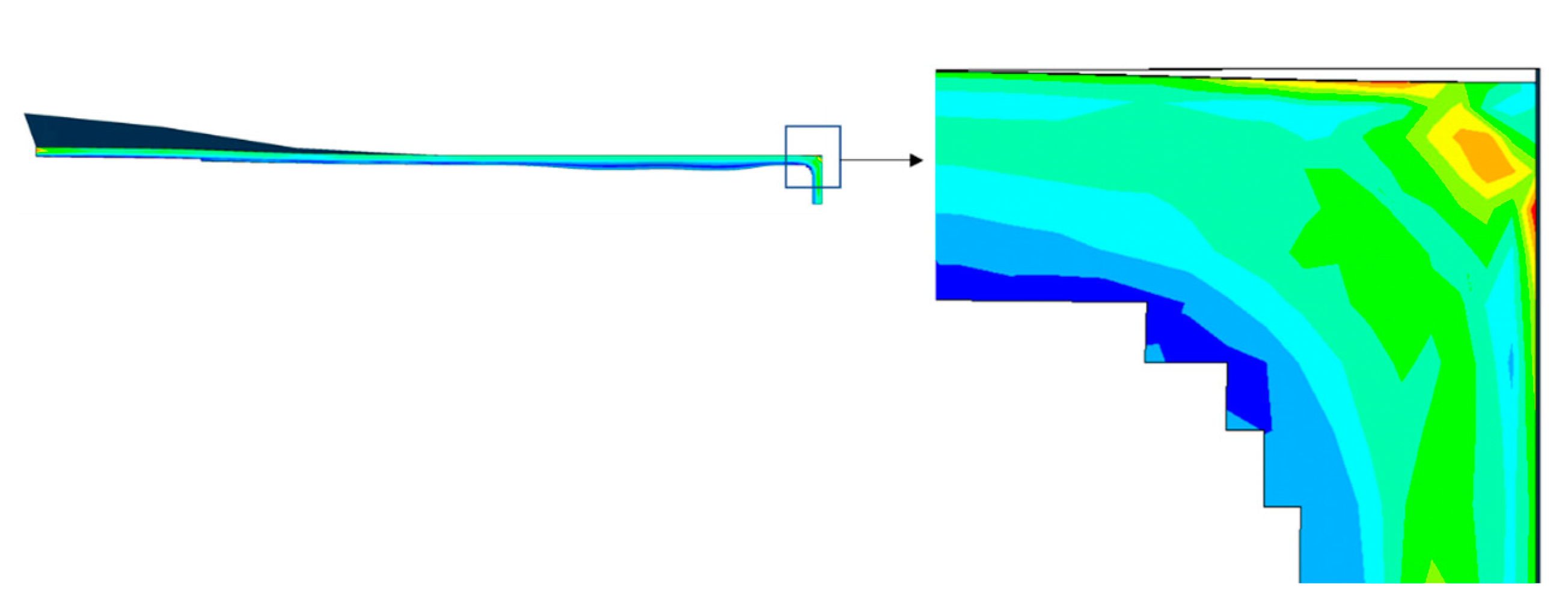
Figure 4 shows the distribution of the gap between the shell and the copper wall at the outlet of the mold, and the blank area at the corner of the figure is the gap area. As can be seen from the figure, there is a small gap between the corner of the slab shell and the copper wall at the outlet of the mold, while in most other areas, the slab shell forms close contact with the copper wall of the mold.
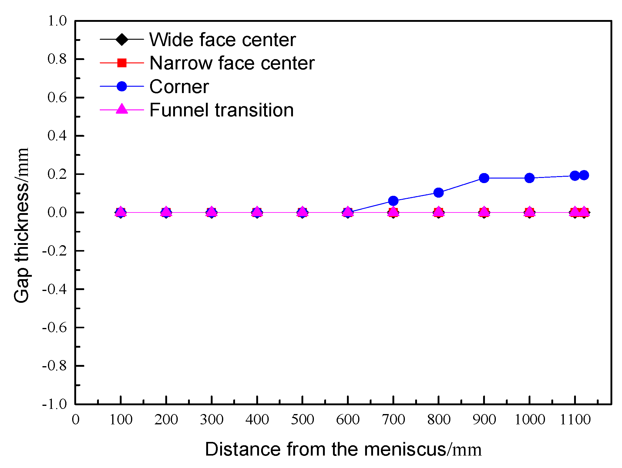
Figure 5 shows the distribution of gap thickness along the drawing direction at the center of the wide face, the center of the narrow face, the corner, and the transition position of the funnel.
It can be seen from the figure that at the position 600 mm below the meniscus, a gap begins to appear at the corners of the slab. At the outlet of the mold, the thickness of the gap at the corner increases to 0.195 mm.
In the upper region of the mold, the thickness of the solidified shell is small, the temperature is high, and the overall stiffness of the shell is small. Under the combined action of the static pressure of the molten steel and the inward extrusion of the shell by the funnel area of the copper wall, the initial shell cannot be separated from the copper wall. Therefore, in the upper area of the mold, a gap cannot be created between the shell and the copper wall, and the shell is tightly attached to the hot surface of the copper wall of the mold.
When the slab moves to the middle and lower areas of the mold, the temperature of the slab shell decreases, the elastic modulus and the yield strength increase, and the thickness of the slab shell increases, so the overall stiffness of the slab shell increases. At the same time, the curvature change of the funnel area of the copper wall slows down, or disappears completely, and the extrusion effect of the copper wall on the slab shell gradually weakens. Finally, under the action of solidification shrinkage, the gap begins to gradually form between the shell and the mold. There is no gap in the center of the wide face, the center of the narrow face, or the transition position of the funnel under the action of the static pressure of the molten steel.
4.3. The First Principal Stress Distribution of the Shell
The stress state at a point on the shell is represented by the shear force being zero and only normal stress acting. The stress tensor of a point on the shell can completely determine the stress state of a point.
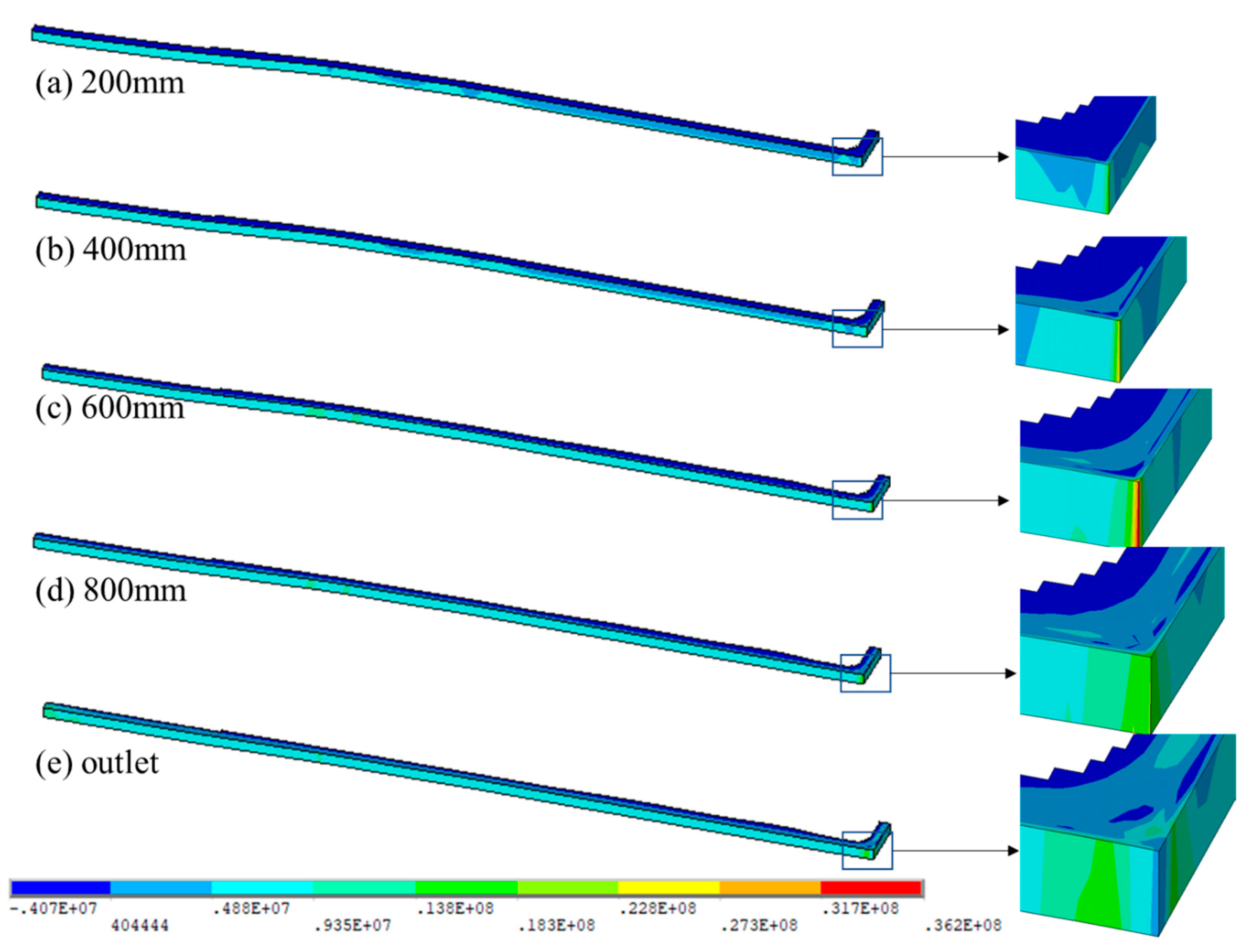
The stress field in the shell is in a three-dimensional stress state, and the first principal stress value can be used to characterize the local crack tendency of the shell. Figure 6 shows the distribution of the first principal stress in the shell at different heights of the mold.
The contour scale in the figure shows the stress value of the first principal stress. A positive value indicates that there is local tensile stress in the shell, and a negative value shows the compressive stress of the shell. It can be seen from Figure 6 that at different heights of the mold, there is a maximum tensile stress in the corner area of the slab shell, and the position of the solidification front is affected by the maximum compressive stress. At the same time, the surface of the shell and the interior of the shell are in the states of tensile stress and compressive stress, respectively.
Except for the corner area in the middle and lower parts of the mold, the surface of the slab shell in most areas is in close contact with the copper wall and is forced to cool by the copper wall of the mold, resulting in a large amount of solidification shrinkage. At the same time, the inner layer of the slab shell is in contact with the molten steel and still maintains a high temperature; the temperature change is small, and the shrinkage of the inner layer of the slab shell is much smaller than that of the surface layer of the slab shell. The shrinkage of the surface shell is constrained by the inner shell, resulting in tensile stress in the surface area of the shell. From the surface layer to the solidification front, the tensile stress gradually decreases and then changes to compressive stress.
At the positions of 200 mm, 400 mm, 600 mm, 800 mm, and 1120 mm (the outlet of the mold) away from the meniscus, the maximum values of the first principal stress appear in the corner area of the shell, and the maximum values are 19.7 MPa, 32.2 MPa, 36.9 MPa, 31.8 MPa, and 29.6 MPa.
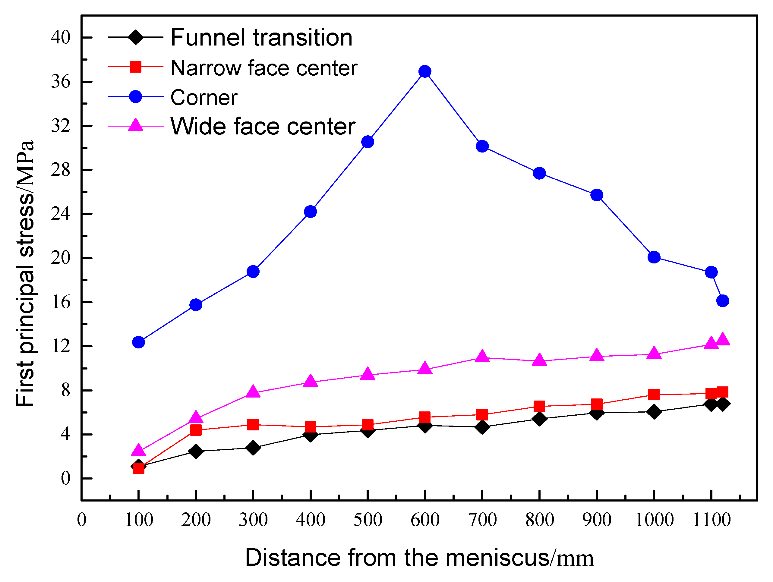
Figure 7 shows the variation distribution of the first principal stress along the drawing direction at typical positions of the shell.
It can be seen from the variation rule of the first principal stress that at the same mold height, the first principal stress in the corner region of the slab shell is larger than the stress value at other positions. When the shell moves downward, the first principal stress increases gradually in the center of the wide face, the center of the narrow face, and the transition position of the funnel. At the outlet of the mold, at the center of the wide face, the center of the narrow face, and the transition position of the funnel, the first principal stress values reached 12.5 MPa, 7.9 MPa, and 6.8 MPa, respectively.
It can be seen from the change rule of the first principal stress of the corner shell that the first principal stress value increases first and then decreases when the shell moves from the upper part of the mold to the outlet of the mold. The first principal stress reaches the peak value of 36.9 MPa at 600 mm in the middle of the mold.
The initial shell moves down the mold from the initial fully solidified position. The surface curvature of the funnel area on the upper part of the mold is large, and the extrusion effect on the downward slab shell is strong. When the slab shell moves down, the slab shell in the funnel area extends outward, and the corner cannot form a gap until it reaches 600 mm below the meniscus. When the shell moves down from the initial fully solidified position to a position below 600 mm below the meniscus, the formation of a gap in the corner regions begins. Therefore, the pressure between the shell and the copper wall in the upper part of the mold increases, and the friction force increases, resulting in an increase in the value of the first principal stress in the corner region.
The slab shell continues to move downward, the funnel curvature change is slowed down, and the extrusion effect on the slab shell is weakened. In the region of 600 mm below the meniscus, tiny gaps begin to form at the corners. The friction between the corner area of the slab shell and the copper wall gradually decreases, resulting in the decrease in the first principal stress. At the outlet of the mold, the value of the first principal stress at the corner is reduced to 16.1 MPa.
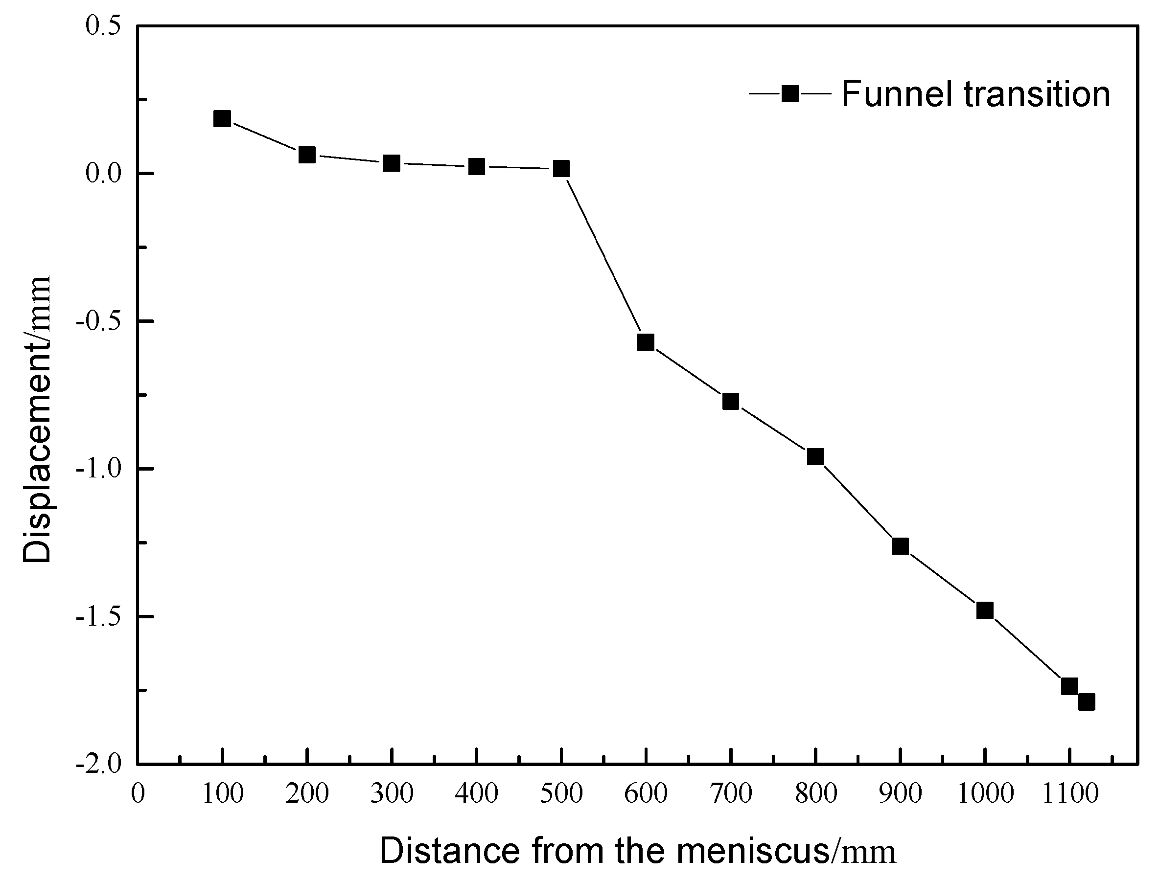
4.4. Transverse Displacement of Shell Surface
Figure 8 shows the variation rule of the lateral displacement of the transition position of the funnel along the drawing direction. Negative displacement indicates that the shell moves toward the funnel area, and positive displacement indicates that the shell moves toward the parallel area. As can be seen from Figure 8, from the position of complete initial solidification to the position 500 mm below the meniscus, the initial shell in the transition zone moves towards the parallel zone of the mold. In the upper part of the mold, when the shell moves down, it is affected by the high-speed curvature change of the funnel area of the mold. The extension of the shell to the narrow copper wall is greater than the cooling shrinkage of the shell itself, and the shell moves toward the direction parallel to the mold.
The slab shell continues to move downward to the outlet of the mold, and in the middle and low area below the meniscus 500 mm, the slab shell in the transition zone moves toward the funnel area. With the gradual disappearance of the mold copper wall funnel region curve, the outward extrusion of the funnel region on the slab shell gradually decreased. The cooling shrinkage of the wide shell is dominant, and the shell in the transition zone begins to move toward the funnel zone. At the outlet of the mold, the displacement of the shell in the funnel transition area towards the funnel area reaches 1.79 mm.
4.5. Model Validation
The model results show that the principal stress at the corners is significantly higher than that at other positions during the downward process of the slab. The corner of the slab is in contact with the copper wall, and the stress on the slab shell at the corner of the slab is more complicated. The first principal stress value can be used to characterize the local crack tendency of the shell, and the first principal stress value at the corners is the largest, which corresponds to the situation where cracks are prone to occur at the corners.
As the slab moves down, the curvature of the funnel area gradually decreases, and the slab shell in the funnel area is forced to squeeze by the mold. The close contact between the shell and the copper wall has a large frictional force, resulting in serious wear on the narrow face of the mold copper wall.
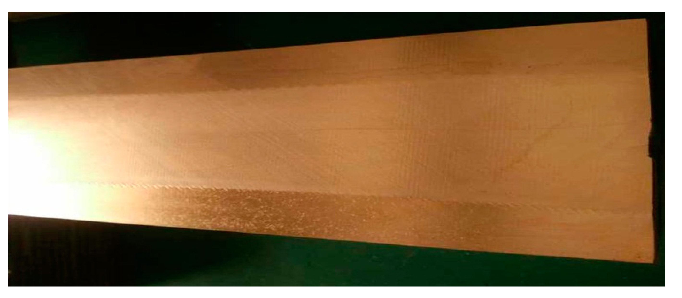
In order to improve the influence of shell displacement and stress on the copper wall, we accurately measured the wear degree of the narrow-face copper wall of the FTSC mold at different positions, and based on this, we designed and manufactured a new narrow-face copper wall (as shown in Figure 9). By artificially thinning the narrow face corner region of the mold at different heights, the deformation space of the shell corner extension is compensated. Production tests show that the thinning design of the narrow-face corners has achieved remarkable results. After the new copper wall is put into use, the crack defect rate at the corners of the slab shell is greatly reduced.
5. Conclusions
Based on the 3D slab heat transfer model, a 3D slab stress model has been developed. The three-dimensional slab stress field of SPHC under the condition of a casting speed of 5 m/min has been obtained.
- (1)
- From the initial complete solidified position of the slab to the position 600 mm below the meniscus, the surface of the slab is in close contact with the copper wall. As the slab continues to move downward, the gap at the corner position is gradually formed. At the mold outlet position, the corner gap thickness is 0.195 mm. At the center of the narrow face, the funnel transition, and the center of the wide face, there is no gap between the shell and the copper wall.
- (2)
- The distribution rule of the first principal stress of the shell shows that the maximum value of the first principal stress appears at the corner. In the slab drawing direction, the first principal stress at the corner of the slab shell first increases and then decreases. The peak value of the first principal stress appears at 600 mm below the meniscus, and the maximum value is 36.9 MPa. At the center of the wide face, the center of the narrow face, and the transition position of the funnel, the first principal stress of the shell increases gradually with the increase in the distance from the meniscus.
- (3)
- At the upper part of the mold, the shell of the funnel transition zone is shifted to the parallel zone. When the shell moves down to 500 mm below the meniscus, the shell in the transition zone begins to move towards the funnel zone. At the exit of the mold, the slab shell is shifted 1.79 mm towards the funnel area.
- (4)
- By compensating for the corner deformation space, a new copper wall was designed for production, and it was found that the cracks at the corner of the slab shell were greatly reduced.
Author Contributions
Z.L. and L.Z. (Liguang Zhu) conceived and designed the study; L.Z. (Luping Zhang) performed the numerical calculation; Y.Y. and P.X. conducted the experiment; Y.Y. wrote the paper. All authors have read and agreed to the published version of the manuscript.
Funding
This research was funded by the National Natural Science Foundation of China Project (51904107), Hebei Natural Science Foundation Projects (E2020209005, E2021209094), Hebei Provincial Colleges and Universities Science and Technology Wood Research Project (BJ2019041), Hebei Province “Three Three Three Talent Project” funded project (A202102002), and Tangshan City Talent funding project (A202010004).
Data Availability Statement
The data presented in this study are available on request from the corresponding author. The data are not publicly available due to privacy restrictions.
Acknowledgments
This work was supported by the National Natural Science Foundation of China Project (51904107), Hebei Natural Science Foundation Projects (E2020209005, E2021209094), Hebei Provincial Colleges and Universities Science and Technology Wood Research Project (BJ2019041), Hebei Province “Three Three Three Talent Project” funded project (A202102002), and Tangshan City Talent funding project (A202010004). The authors are grateful for their financial support.
Conflicts of Interest
The authors declare no conflict of interest.
References
- Park, H.-S.; Nam, H.; Yoon, J.K. Numerical Analysis of Fluid Flow and Heat Transfer in the Parallel Type Mold of a Thin Slab Caster. ISIJ Int. 2000, 41, 974–980. [Google Scholar] [CrossRef]
- Klinkenberg, C.; Kintscher, B.; Hoen, K.; Reifferscheid, M. More than 25 Years of Experience in Thin Slab Casting and Rolling Current State of the Art and Future Developments. Steel Res. Int. 2017, 88, 1700272. [Google Scholar] [CrossRef]
- Sobral, M.D.C.; Mei, P.R.; Santos, R.G.; Gentile, F.C.; Bellon, J.C. Laboratory simulation of thin slab casting. Ironmak. Steelmak. 2003, 30, 412–416. [Google Scholar] [CrossRef]
- Sivak, B.A. Mathematical modeling of the shape of the cavity of a thin-slab continuous-casting mold. Metallurgist 2012, 55, 912–917. [Google Scholar] [CrossRef]
- Ramacciotti, A. Thermo-mechanical behaviour of the solidified shell in a “funnel-shaped” mold for continuous casting of thin slabs. Steel Res. 1988, 59, 438–448. [Google Scholar] [CrossRef]
- Oconnor, T.G.; Dantzig, J.A. Modeling the thin-slab continuous-casting mold. Met. Mater. Trans. B 1994, 25, 443–457. [Google Scholar] [CrossRef]
- Ha, J.; Cho, J.; Lee, B.; Ha, M. Numerical analysis of secondary cooling and bulging in the continuous casting of slabs. J. Mater. Process. Technol. 2001, 113, 257–261. [Google Scholar] [CrossRef]
- Vakhrushev, A.; Kharicha, A.; Wu, M.; Ludwig, A.; Nitzl, G.; Tang, Y.; Hackl, G.; Watziger, J.; Rodrigues, C.M.G. On modelling viscoplastic behavior of the solidifying shell in the funnel-type continuous casting mold. In IOP Conference Series: Materials Science and Engineering; IOP Publishing: Bristol, UK, 2019; Volume 529, p. 012081. [Google Scholar] [CrossRef]
- Liu, X.; Zhu, M.; Cheng, N. Study on the thermal behavior in slab continuous casting mold. Acta Metall. Sin. 2006, 42, 1081–1086. [Google Scholar] [CrossRef]
- Zhang, H.; Wang, W. Mold Simulator Study of Heat Transfer Phenomenon During the Initial Solidification in Continuous Casting Mold. Met. Mater. Trans. B 2017, 48, 779–793. [Google Scholar] [CrossRef] [Green Version]
- Song, J.-X.; Cai, Z.-Z.; Piao, F.-Y.; Zhu, M.-Y. Heat Transfer and Deformation Behavior of Shell Solidification in Wide and Thick Slab Continuous Casting Mold. J. Iron Steel Res. Int. 2014, 21, 1–9. [Google Scholar] [CrossRef]
- Marukovich, E.I.; Demchenko, E.B. Heat transfer in the mold during vertical continuous casting of steel. Litiyo I Metall. 2018, 26–30. [Google Scholar] [CrossRef]
- Na, X.-Z.; Xue, M.; Zhang, X.-Z.; Gan, Y. Numerical Simulation of Heat Transfer and Deformation of Initial Shell in Soft Contact Continuous Casting Mold Under High Frequency Electromagnetic Field. J. Iron Steel Res. Int. 2007, 14, 14–21. [Google Scholar] [CrossRef]
- Hu, S.; Wang, P.; Zhu, L.; Liu, Z.; Xiao, P. Analysis of heat transfer in thin slab funnel shape mold. Iron Steel 2017, 52, 33–37. [Google Scholar] [CrossRef]
- Lan, P.; Li, L.; Tie, Z.; Tang, H.; Zhang, J. Combined Study on Mold Taper and Corner Radius in Bloom Continuous Casting by FEM Simulation and Trial Experiment. Met. Mater. Int. 2019, 25, 1603–1615. [Google Scholar] [CrossRef]
- Xia, Y.-J.; Wang, F.-M.; Li, C.-R.; Wang, J.-L. Simulation of thermomechanical behavior during continuous casting process based on MiLE method. J. Central South Univ. 2012, 19, 2403–2410. [Google Scholar] [CrossRef]
- Xiao, P.; Liu, Z.; Zhu, L.; Wang, Z.; Piao, Z. 3D Heat Conductivity Model of Mold Based on Node Temperature Inheritance. High Temp. Mater. Process. 2018, 38, 92–100. [Google Scholar] [CrossRef]
- Zhang, L.; Xiao, P.; Liu, Z.; Zhou, J.; Zhu, L. Heat transfer behavior in ultrahigh-speed continuous casting mold. High Temp. Mater. Process. 2021, 40, 370–381. [Google Scholar] [CrossRef]
- Liu, Z.; Zhang, Z.; Xiao, P.; Zhou, J.; Zhu, L. Influence of cooling process on heat transfer of high-speed continuous casting mold. Iron Steel 2021, 56, 41–48. [Google Scholar] [CrossRef]
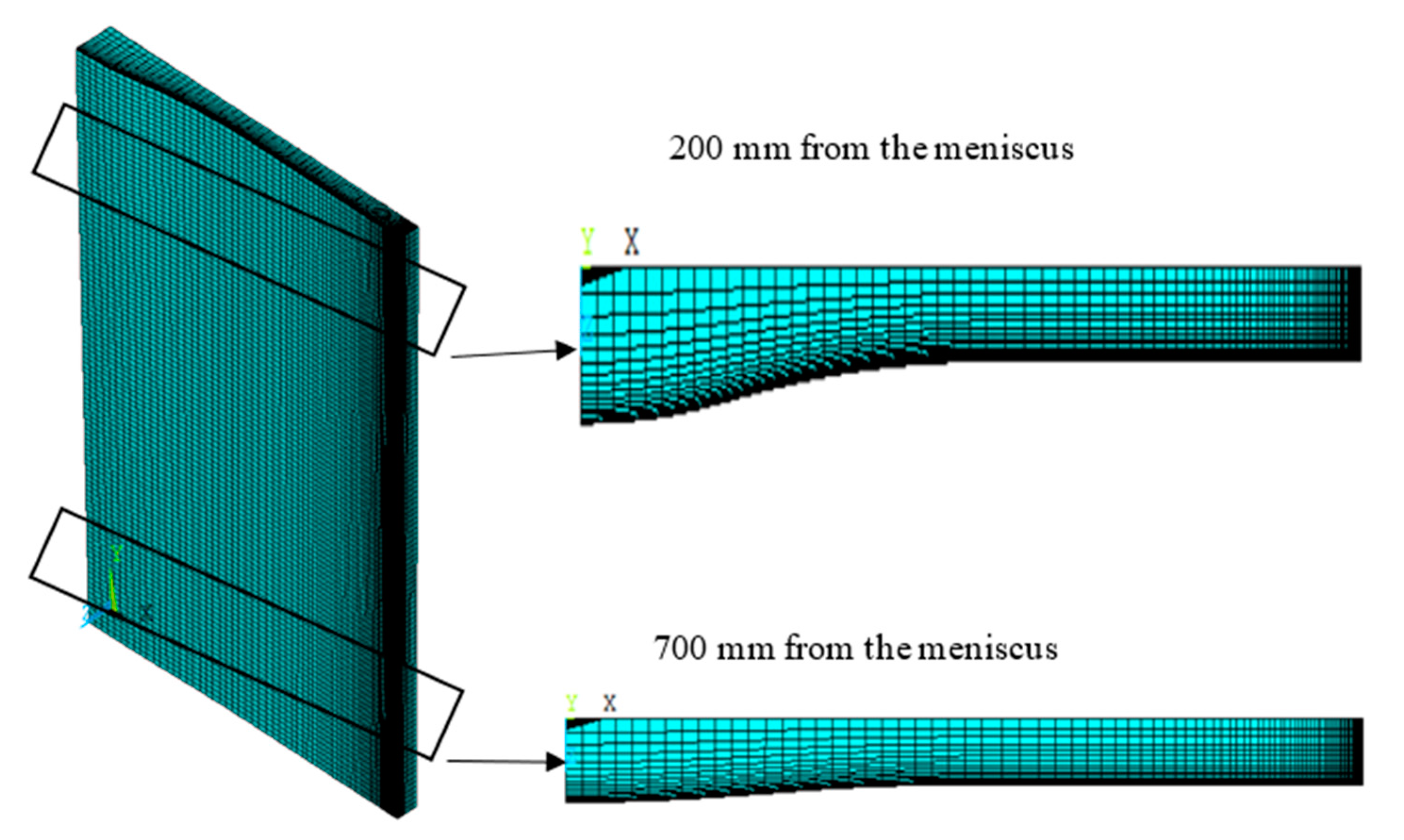
Figure 1.
The 3D stress finite element model.

Figure 2.
The 3D slab temperature field under typical conditions.

Figure 3.
Surface temperature distribution of slab under typical working conditions. (a) Narrow face temperature. (b)Wide surface temperature.
Figure 3.
Surface temperature distribution of slab under typical working conditions. (a) Narrow face temperature. (b)Wide surface temperature.

Figure 4.
Mold outlet gap.

Figure 5.
Gap distribution along the drawing direction at typical locations.

Figure 6.
(a–e) Distribution of the first principal stress of the shell at different heights from the mold meniscus.
Figure 6.
(a–e) Distribution of the first principal stress of the shell at different heights from the mold meniscus.

Figure 7.
Variation rule of first principal stress of shell in typical region.

Figure 8.
Variation rule of lateral displacement of shell surface in funnel transition zone.

Figure 9.
Narrow-face copper wall after FTSC corner thinning design.


Table 1.
Continuous casting process parameters.
| Project | Value | Unit |
|---|---|---|
| Casting speed | 5 | m·min−1 |
| Pouring temperature | 1550 | °C |
| Taper | 6 | mm |
| Temperature of cooling water | 30 | °C |
| Flow rate of cooling water | 10 | m·s−1 |
| Wide/narrow surface Wide/narrow face cooling water quantity | 3630/530 | L·min−1 |
| Effective height of mold | 1120 | mm |
| Slab width | 1470 | mm |
| Slab thickness | 90 | mm |
| Friction coefficient of copper wall | 0.1 |
Table 2.
Main components, solidus temperature, and liquidus temperature of the steel grade.
| Steel Composition | C | Si | Mn | P | S | TL/°C | TS/°C |
|---|---|---|---|---|---|---|---|
| SPHC | 0.060 | 0.020 | 0.300 | 0.018 | 0.005 | 1527 | 1478 |
Disclaimer/Publisher’s Note: The statements, opinions and data contained in all publications are solely those of the individual author(s) and contributor(s) and not of MDPI and/or the editor(s). MDPI and/or the editor(s) disclaim responsibility for any injury to people or property resulting from any ideas, methods, instructions or products referred to in the content. |
© 2023 by the authors. Licensee MDPI, Basel, Switzerland. This article is an open access article distributed under the terms and conditions of the Creative Commons Attribution (CC BY) license (https://creativecommons.org/licenses/by/4.0/).
Share and Cite
MDPI and ACS Style
Liu, Z.; Yang, Y.; Xiao, P.; Zhu, L.; Zhang, L. Analysis of Uneven Wear Mechanism of Narrow-Face Copper Wall of Funnel Mold. Metals 2023, 13, 666. https://doi.org/10.3390/met13040666
AMA Style
Liu Z, Yang Y, Xiao P, Zhu L, Zhang L. Analysis of Uneven Wear Mechanism of Narrow-Face Copper Wall of Funnel Mold. Metals. 2023; 13(4):666. https://doi.org/10.3390/met13040666
Chicago/Turabian StyleLiu, Zengxun, Yaosen Yang, Pengcheng Xiao, Liguang Zhu, and Luping Zhang. 2023. "Analysis of Uneven Wear Mechanism of Narrow-Face Copper Wall of Funnel Mold" Metals 13, no. 4: 666. https://doi.org/10.3390/met13040666
Note that from the first issue of 2016, this journal uses article numbers instead of page numbers. See further details here.