
Atomistic-Continuum Constitutive Modeling Connection for Gold Foams under Compression at High Strain Rates: The Dislocation Density Effect

1
Department of Civil and Environmental Engineering, University of Missouri, Columbia, MO 65201, USA
2
Computational Solid Mechanics Laboratory, Department of Civil and Environmental Engineering, Louisiana State University, Baton Rouge, LA 70803, USA
*
Author to whom correspondence should be addressed.
Metals 2023, 13(4), 652; https://doi.org/10.3390/met13040652
Submission received: 13 February 2023
/
Revised: 18 March 2023
/
Accepted: 21 March 2023
/
Published: 25 March 2023
(This article belongs to the Special Issue Editorial Board Members’ Collection Series: Metal Crystal/Polycrystal Plastic Strain Hardening)
Abstract
:Constitutive description of the plastic flow in metallic foams has been rarely explored in the literature. Even though the material is of great interest to researchers, its plasticity remains a topic that has a much room for exploration. With the help of the rich literature that explored the material deformation mechanism, it is possible to introduce a connection between the results of the atomistic simulations and the well-established continuum constitutive models that were developed for various loading scenarios. In this work, we perform large-scale atomistic simulations of metallic gold foams of two different sizes at a wide range of strain rates () under uniaxial compression. By utilizing the results of those simulations, as well as the results we reported in our previous works, a physical atomistic-continuum dislocations-based constitutive modeling connection is proposed to capture the compressive plastic flow in gold foams for a wide range of sizes, strain rates, temperatures, and porosities. The results reported in this work present curated datasets that can be of extreme usefulness for the data-driven AI design of metallic foams with tunable nanoscale properties. Eventually, we aim to produce an optimal physical description to improve integrated physics-based and AI-enabled design, manufacture, and validation of hierarchical architected metallic foams that deliver tailored mechanical responses and precision failure patterns at different scales.
1. Introduction
Cellular solids have always attracted attention because they have one of the most desirable material characteristics that a researcher could ask for, and that is a high stiffness-to-weight ratio [1]. This promotes the material capacity to be used in a wide range of applications; it is excellent in terms of shock absorbency [1,2], energy absorbency as the core of sandwich metal tubes [3,4], catalysts [5,6,7], sensors and super capacitors [8,9,10,11,12], actuators [13], and radiation-tolerant materials [14,15,16]. Bicontinuous metallic nanofoam, which is a class of cellular solid, is made of a network of interconnected ligaments and pores. This material, which is the subject of this work, has been researched for some time by using various approaches, including pure experimental work (continuum scale) [17,18,19,20,21,22,23] and pure computer simulations (mainly atomistic scale) [24,25,26,27,28,29,30,31]. Despite the fact that there were trials to directly compare the results of molecular dynamics (MD) simulations with the results of experiments [32,33,34,35], no adequate connection has been made between the two scales in terms of the constitutive description of the material plastic flow. In fact, a constitutive description of the plastic flow of metallic nanofoams has rarely been explored in the literature. That can be attributed first to the fact that constitutive description of the plastic flow of any full density (nonporous) solid is a very challenging task, given that there are a lot of variables that play important roles in the material response (size, strain rate, temperature, crystal structure, etc.). Additionally, for the case of bicontinuous metallic nanofoam, there is the added complexity of having more variables to take into account, such as porosity, network connectivity, structural disorder, and free surface effects. All of this makes atomistic simulations of the plasticity of nanofoams computationally expensive and structurally complex.
However, this should not hold researchers back from trying to provide the required constitutive models that capture the material response. The need for either physical or phenomenological constitutive models is a fundamental necessity. For example, it is required to ensure the applicability of the second law of thermodynamics in the continuum description of a system in equilibrium in addition to the basic laws of mass, energy, and momentum conservation. Without the constitutive models, we will end up with a number of equations less than the number of unknowns, and in turn, produce a nonsolvable scheme. In other words, unlike atomistic simulations, which are dependent on the interatomic potential description rather than the constitutive description, continuum-based simulations are extremely dependent on constitutive description. For example, constitutive models that account for material deformation mechanisms as well as the effects of temperature, strain rate, size, and density are required to perform continuum-based simulations such as finite element (FE) and/or meshless-based simulations. Therefore, the challenge becomes more about what constitutive model to use or to develop rather than discussing the need for those constitutive descriptions.
To avoid repeating the works of others, and because we would not provide any better extensive comparisons between different existing constitutive models than those provided by references [36,37,38,39,40], we would refer the readers to those references. In general, to choose a suitable continuum-based constitutive model to describe the plastic flow of foams, especially that those constitutive models were originally developed for full density (nonporous) solids, a physical-based constitutive model should be the first type to consider. Additionally, because the deformation mechanism of gold metallic foams is controlled by dislocation mechanics, as explained extensively in the literature and in our previous works [25,26,29,30,31,41,42,43], the physical-based constitutive model needs to be dislocation-controlled. As we will show later, the only available constitutive description for gold foams is based on dislocation dynamics. Moreover, the flexibility of determining the material constants from a limited set of experimental data and capturing the static and/or dynamic behavior should be considered in the selection process. For those reasons, among the well-known available constitutive models in the literature [38,44,45,46,47,48,49,50], we choose to use the Voyiadjis–Abed (VA) constitutive model [49] which is a modified/extension version of the well-known Zerilli–Armstrong (ZA) constitutive model [47]. In later sections, we provide more details on the theory that promotes the constitutive model efficiency, aside from it being flexible in determining its parameters.
There were few attempts in the literature to explore the constitutive modeling of the plastic flow in metallic foams [51,52,53,54,55,56]. However, to the best of authors’ knowledge, there were no trials in developing a physical-based and dislocation-based constitutive model for that matter. Moreover, there is no known effort in establishing a connection between any physical-based continuum constitutive model and the atomistic observations of the material behavior. The proposed work utilizes a continuum, physical-based, and dislocation-based constitutive model to provide a physical meaning and to modify the authors’ previously published atomistic constitutive description in metallic foams. The newly proposed constitutive model will establish a connection between the two scales (atomistic and continuum). Accordingly, we report the first trials to propose a connection between atomistic and continuum constitutive description of the plastic flow of face center cubic (FCC) nanofoams after performing large-scale MD simulations of different sizes and strain rates of gold foam. In Section 2, the authors recall the dislocation-based atomistic constitutive description of gold foams proposed in their previous publications. In Section 3, the authors review the dislocation-based continuum constitutive description of plasticity in nonporous FCC metals as proposed by Voyiadjis and Abed [57]. In Section 4, the authors introduce the proposed connection between the atomistic and the continuum constitutive models. In Section 5, the computational modeling part is presented, in which large-scale MD simulations are performed over a wide range of strain rates for two different average ligament sizes. The results of those simulations in addition to the results of the simulations that were reported by the authors in their previous works are used to test the proposed atomistic-continuum connection. In Section 6, the results are discussed in light of the simulations.
2. Atomistic Dislocation-Based Constitutive Model for Gold Foams
In this section, the authors recall the atomistic constitutive model that was developed by the same authors in their previous work [29,30,31,58]. Saffarini et al. [29] proposed an expression to describe the plastic flow in gold foams under compression as a function of the total dislocation density, as well as other phenomenological parameters. The parameters were determined based on large-scale simulations that were conducted for a range of ligament sizes, temperatures, and strain rates. However, no coupling effect was considered during the development of the formulation. In other words, every series of simulations was done by varying one aspect and fixing all others. The proposed expression is shown in Equation (1),
where is the yield strength, C is a size dependent constant, D is a stress parameter that is size- and temperature-dependent, n () is an exponent that is related to the ligament area and is size- and strain rate-dependent, and () is the total dislocation density. Table 1 shows the values of Equation (1) parameters as provided by Saffarini et al. [29].
The constitutive model suggests that the plastic flow in gold foam can be decomposed into two stress components: (1) a yield-controlled stress component, and (2) dislocation-controlled hardening (densification) stress component. The second component corresponds to the amount of stress needed to continuously ensure the nucleation of dislocations in gold foams to plastically deform the material. Due to the small ligament size and the presence of porosity that typically comprise the microstructure of the foam, dislocations annihilate almost instantly upon nucleation by escaping at the ligament’s free surfaces. This type of dislocation interaction and accumulation mechanism prior to densification requires a continuous supply of stress to plastically deform the material. For more details about the dislocation dynamics controlling the deformation mechanism, the reader is referred to the authors’ previous works [29,30,31].
The hardening term in Equation (1) takes the exponential form to capture the densification regime that is dominant in all cellular materials under compression. As shown by Saffarini et al. [31], this regime is initiated once the material transforms from being open-cell foam into closed-cell foam, losing its bicontinuous microstructure and allowing dislocation to accumulate and interact without being annihilated [29].
The total dislocation density () variable that appears in Equation (1) can be determined by using the formulation that Saffarini et al. [29] previously proposed. The developed exponential expression describes the evolution of total dislocation density as a function of relative density under compression.
Aside from the effect of relative density, the effect of ligament size, strain rate, and temperature are captured by the remaining phenomenological parameters. The model is described by Equation (2),
where is the total dislocation density, A () and B () are parameters that capture the coupling effect of size, temperature, and strain rate, and m (m2) is an exponential decay factor that is size-dependent only (i.e., strain rate- and temperature-independent). Table 2 shows the values of the parameters as reported in their work.
3. Continuum Dislocation-Based Constitutive Model for Nonporous FCC Metals
Plastic deformation in FCC metals is controlled by dislocations’ motion and their respective interactions, which are well established by the dislocation theory [59]. Accordingly, constitutive models describing metal plasticity were developed to accommodate the microscopic interaction of dislocations and how they control the deformation and the stress evolution upon initiation of plasticity. In this section, a brief overview is presented of the continuum dislocation-based constitutive model that is utilized to establish the connection with the atomistic constitutive description described in the previous section. Specifically, we refer to the dislocation dynamics theory in full density (nonporous) FCC metals as the basis of this proposed connection.
Voyiadjis and Abed [49] developed a physical- and dislocation-based constitutive model that describes the plastic flow in FCC metals over a wide range of strain rates and temperatures based on the concepts of thermal activation processes that were proven to control dislocation dynamics at low strain rates. They modified the ZA constitutive model [47], to overcome two major shortcomings. The first is that the explicit definition of one of its parameters which assumes that the thermal activation area is constant instead of being temperature-dependent. The second shortcoming is that the model assumes a simple mathematical expansion that can be only applicable for very low strain rates and temperature ranges. Such an assumption limits the usage of the model with regard to the reference strain rate. Accordingly, Voyiadjis and Abed [47] proposed significant modifications to those assumptions. Here, we present the final form of the VA constitutive model which will be used later to provide the physical basis for our proposed continuum-atomistic connection.
In FCC metals in particular, the plastic deformation is dominated by the evolution of a “heterogeneous microstructure of dislocations (mobile)” and the long-range intersections between dislocations (forest), especially at strain rates less than . For that, the thermal activation analysis depends on plastic strain [49]. Moreover, dislocations during plastic deformation can be cumulatively trapped to form a forest of dislocations. Forest dislocations act as a barrier that hinders the motion of mobile dislocations. Overcoming such a barrier requires introducing thermal energy that in turn can provide thermal hardening. For that reason, the plastic flow stress must contain a thermal component that is dependent on the plastic strain. Moreover, because “slip-crystal flow stress” is controlled by dislocation density and intersections (activation area), this thermal component of the stress is proportional to the inverse square root of the plastic strain. Accordingly, the VA constitutive model decomposes the stress response of the material into athermal stress () and thermal stress () components as shown by Equation (3):
The athermal stress component is plastic strain-independent and is completely related to the initial yield stress . Since there is no strain rate and temperature dependency on the initial yield stress, becomes constant. The thermal stress component describes the coupling effect of temperature, strain rate, and plastic strain. Based on that, Voyiadjis and Abed [47] presented the final form of the total flow stress expression as shown by Equation (4),
where is a hardening parameter and is defined as , parameter is the resultant drag-stress at the reference velocity or zero absolute temperature and is defined as , constants p and q define the shape of the obstacle where p ranges from 0 to 1, and q ranges from 1 to 2. Moreover, the thermal activation parameter is defined as with parameters and defined as and where is the Boltzmann’s constant, is Burger’s vector, is the dislocation density, is the dislocation velocity, and is the reference Gibbs free energy.
4. Proposed Atomistic-Continuum Constitutive Connection
Except for a few constitutive models [45,60], most of the existing continuum constitutive models that describe the plastic flow in FCC metals, including the one presented earlier, were well-established for strain rates less than because they were developed by using the concept that thermal activation processes are the driving force for the motion of dislocation. For the case of higher strain rates than , and specifically at certain threshold values, there will be an “upturn” in the flow stress as proven experimentally by Follansbee and Kocks [50]. In more detailed terminology, there appears to be a rise in the strain rate sensitivity at such level of strain rates. For that reason, those constitutive models need to be revisited to include a description that considers some of the physics that are driving this strain rate sensitivity. That is, the constitutive model’s parameters need to either be reevaluated, expanded, or combined with additional parameters.
Despite the upturn in flow stress being an experimental fact, the main driving force behind it is still debatable [37]. Follansbee and Kocks [50] stated that it is still controlled by thermal activation processes instead of the dislocation drag. Rusinek et al. [61] emphasized that it is controlled by both dislocation drag and thermal activation. Zerilli and Armstrong [62] showed that dislocation drag is not the driving force because strain under tension does not increase as it should if dislocation drag is active. This means that there is an unclear thermal-activation-guided process that is playing a key role. However, as shown by Saffarini et al. [30], the dislocation evolution becomes significantly high at very high strain rates due to the rapid nucleation and annihilation of dislocations, as well as the speed at which they move. Such phenomena are difficult to attribute to thermal activation processes and are believed to be controlled by dislocation drag [62,63].
Following this debate, several trials ranging from attributing the strain rate sensitivity to structure evolution, redefining the dislocation spacing and density, to introducing a “characteristic length evolution” parameter, were made to explain the upturn in flow stress [50,64,65]. Despite the fact that those trials do not exactly match the case we are presenting in this work, they fall under the same umbrella. It is shown later that the main goal of this proposed connection and modification is to combine terms that attribute dislocation behavior under very high strain rates in metallic foams to both the thermal activation processes (especially yielding) and dislocation drag (especially hardening and densification).
All of the abovementioned studies concluded that the rate of dislocations’ evolution at very high strain rates is significantly higher, and in turn, this increases the dislocation density and decreases the dislocation spacing, activation area, and other characteristic lengths. This is believed to induce the upturn in the stress [37]. For that reason, there needs to be a dedicated term in our proposed constitutive model that describes the unique, abrupt change in the dislocation interactions at such high strain rate, which in turn captures the said significant increase in dislocation density and the corresponding material hardening. Moreover, because the dislocation spacing and interaction in metallic foams is defined mainly by the material porosity [30,31], the effect of porosity (relative density) needs to be a fundamental aspect of the constitutive model (see Equations (2), (8) and (10)).
As explained earlier, at very high strain rates, it is debatable whether the upturn in stress is controlled solely by thermal activation processes or by dislocation drag. We show here that adopting a constitutive description that combines a derivation based on the concept of thermal activation and a phenomenological description of the other processes that were shown to control the deformation mechanisms in metallic foams can accurately capture the stress–strain response of gold foams. By trying to describe the unique dislocation density evolution mechanism in metallic foams, we will be able to capture the stress–strain response of gold foams under compression for different sizes and at strain rates in the range .
Several constitutive models were proposed to describe dislocation density evolution [44,66,67,68,69]. However, it is a slightly different case in this work due to the different nature of the microstructure encountered in metallic foams that are uniquely characterized by the presence of porosity. In other words, the fact that dislocations in the case of porous medium evolve in a different manner than that in nonporous medium plays an important role in the behavior of dislocation evolution. As shown by our previous works [29,30,31], dislocations in porous media travel significantly shorter distances than those in nonporous media because they get annihilated after escaping the solids at the ligament’s surfaces. This leads to the need of a continuous stress increase to renucleate dislocations and plastically deform the material. This process remains active until material compaction reaches a point where the bicontinuous microstructure starts to disappear, and densification is initiated. At that stage, we start to observe some of the dislocation dynamics that occur in full density (nonporous) solids to take place, and thus, significant hardening starts to appear in the material response. However, that does not preclude the fact that dislocation dynamics during the instances when dislocations are traveling within ligaments prior to annihilation (especially before densification initiation), are the same as that in nonporous media. The fact is that the stress response that is controlling the plastic deformation of metallic foams is dominated by dislocation annihilation. Other than that, dislocation dynamics within the solid will still abide by the same dislocation dynamics observed in nonporous media at very high strain rates. Therefore, the following continuum formulation is used to physically justify Equation (2), which determines the dislocation density as a function of relative density in gold foams. The first connection is that the continuum formulation to predict the dislocation density in FCC metals takes the same form as the atomistic formulation as will be shown next. This is because, as stated earlier, the dynamics of dislocations remain the same for porous and nonporous media at very high strain rates.
Armstrong et al. [57,70] pointed out that the activation area decreases significantly and approaches an atomistic dimension when the upturn in flow stress occurs at high strain rates. This means that the dislocation distance will decrease, leading to a dislocation density increase. Accordingly, the hardening parameter controlled by dislocation density can take the form shown by Equation (5),
where is the initial forest dislocation, is the forest dislocations, the forest dislocation density fraction of the total dislocation density, is the Schmidt factor, and is the dislocation annihilation factor. The term shown by Equation (5) can be rewritten to take the form shown by Equation (6),
where the first two terms can be assumed to be constant in a statistical averaging sense while the third term is a varying term as a function of plastic strain. This can help us in rewriting Equation (6) to take a form similar to Equation (2), such that:
where , , and . For the case of metallic foams, as shown previously by Saffarini and coworkers [29,30,31], relative density in our case is directly proportional to the engineering plastic strain, and the dislocation distance. The intersection spacing in metallic foams is in the order of atomic diameter (a factor of the average ligament size ~5 × Atomic Diameter) as Armstrong et al. [57,70] pointed out (see above).
Since the relative density is directly proportional to the engineering plastic strain, as stated earlier, it is used as an alternative representation that describes the average activation area as well as the dislocation distance in the material. This allows one to reasonably and directly replace the plastic strain by the relative density, leading one to rewrite Equation (7) to follow the same form presented in Equation (2) as by Equation (8):
By comparison, one has the parameters of Equation (8) follow the same form presented in Equation (2) such that , , and . By using Equation (8), one can evaluate the second term (hardening stress term) in Equation (1).
Despite the fact that Saffarini et al.’s constitutive model (Equation (1)) has been shown to significantly capture the MD simulation results as displayed in their previous studies [71] and the fact that the second term of the model (dislocation-controlled stress component) is physically justified by the dislocation dynamics reported in their work and well-established by the literature, the first term (yield-controlled stress term) still lacks the required physical reasoning. For that, here one introduces the second continuum-atomistic connection, in which it is proposed that the first part of the atomistic constitutive model (yield-controlled stress component) is directly related to the continuum microscopic description that the VA constitutive model provides. In other words, one proposes the equality shown by Equation (8):
Substituting Equation (9) into Equation (1) gives the proposed model as shown by Equation (10):
where is the dislocation density as determined by Equation (8). That being said, the proposed constitutive model now consists of three components: (1) the stress component that controls the material yielding (athermal stress component), (2) the stress component that controls the thermal activation processes (thermal stress component), and (3) the stress component that controls both the densification (hardening) and the upturn in flow stress due to the effect of very high strain rate (dislocation-controlled hardening stress component). The third stress component is dislocation-controlled and should capture the exponential increase in stress in metallic foams due to the material densification.
5. Computational Modeling
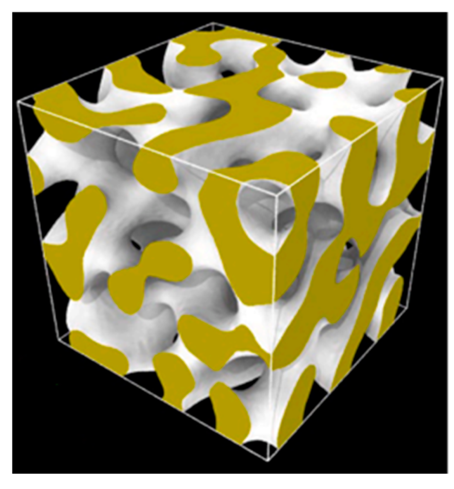
The microstructures of the nanoporous gold samples used in this work simulations were produced by using the phase field method through spinodal decomposition [72,73,74]. More details about the process can be found in our previous work [31] which has the details of generating the samples used in this work. Two Au single crystals were generated; one has the dimensions of 100 × 100 × 100 lattice spacing ( = 4.08 Å), and the other is scaled by a factor of two in each direction. The smaller sample microstructure and morphology is shown in Figure 1 after being postprocessed by using the OVITO surface reconstruction modifier [59,60]. This sample template was applied as is in the finite element solver, and then scaled by a factor of 2 as mentioned earlier to generate the second larger sample. This protocol guarantees self-similarity, the same porosity, and the same network connectivity for both samples. Such conditions will reduce the variability between the two samples, limiting the difference between them to the difference in size and difference in response to strain rate effect. At the end of the process, the first sample ended up containing ~2 million atoms, whereas the second one has ~16 million atoms.
The samples morphologies were characterized using AQUAMI [75] software. This analysis yields that the average ligament diameter for first sample is 6.4 nm and 13.1 nm for the second one. Both generated samples have 50% porosity.
The large-scale atomic molecular massively parallel simulator (LAMMPS) open-source code [76] was used in this work to perform the MD simulations. The Foiles et al. embedded atomic method (EAM) interatomic potential for gold [77] was used for the interatomic interaction. Before performing any production simulations, the statistical minimization of the atomic potential energy was performed by using the conjugate gradient method with a final condition of zero stress in each direction. Upon finalization of energy minimization, a thermal relaxation was performed for each sample to achieve a final target temperature of 300 K and final target pressure of zero over the span of 0.5 ns in NPT ensemble.
For the production simulations, a uniaxial strain through scaling of the simulation box was applied along the [001] direction at four different strain rates of , , , and and room temperature of 300 K while maintaining zero stress condition in the other two perpendicular directions in an NPT ensemble. The 3D periodicity was maintained during all simulation stages (minimization, equilibration, and production). Finally, the visualization and postprocessing was performed by using the OVITO software and crystal analysis tool [78,79,80,81,82].
6. Results and Discussion
In this section, the authors present and discuss the results of the proposed constitutive model compared with the MD simulation results. In addition, they provide a comparison between the proposed constitutive model, the VA constitutive model, and the hardening term in Equation (1) to further show the usefulness of the newly proposed connection.
The stress–strain curves obtained from the simulations were determined based on the global stress tensor of the full sample as per the virial theorem in LAMMPS [83]. The global stress is computed by the formula , where N is the number of atoms in the system, is the Boltzmann constant, is the temperature, d is the dimensionality of the system (2 for 2D, 3 for 3D), and V is the system volume. The second term is the virial, equal to − (U is the potential energy), computed for all pairwise as well as 2-body, 3-body, 4-body, many-body, and long-range interactions, where and are the position and force vector of atom i, and the dot indicates the dot product (scalar product). As for the engineering strain, it is the simple change of length along the load direction since the loading was applied by scaling the simulation box at a predefined rate (refer to Section 5). Accordingly, the global von Mises stress is computed by using Equation (11) to produce the stress-strain plots:
Table 3 and Table 4 show the parameters’ values of Equations (8) and (10), respectively. The parameters of Equation (8) were obtained from Saffarini et al. [29] for all strain rates in the case of the small sample and for the strain rate of in the case of the medium sample. As for the remaining strain rates of the medium sample, the parameters have been evaluated by using the same approach of Saffarini et al. [29] by using the MD simulations performed for this work and as per the definitions of Equation (6).
The parameters of the VA constitutive model part of Equation (10) were determined by using the definition of each parameter as listed in Section 3 and by performing the simple regression analysis explained by Voyiadjis and Abed [49,57] using the results of the small sample. As the table shows, the parameters of the VA constitutive model, except for the yield stress (), are size-independent. The strain rate dependency is captured by the parameter which allows the remaining VA parameters, except for the yield stress, to be strain rate-independent. The yield stress term is both size and strain rate-dependent. Those variations in the parameters’ values, along with their dependencies, are in line with the physical definition of the VA constitutive model described in Section 3, and with the physical meaning intended from combining the VA constitutive model with the hardening term from the Saffarini et al. constitutive model.
The upturn flow stress component, as represented by the hardening stress term in Equation (10), is strain rate-independent because the strain rate contribution is taken care of by and parameters of Equation (8), as well as the parameter in the VA part. Additionally, the size dependency is captured by both the parameters of the upturn stress component and Equation (8) parameters.
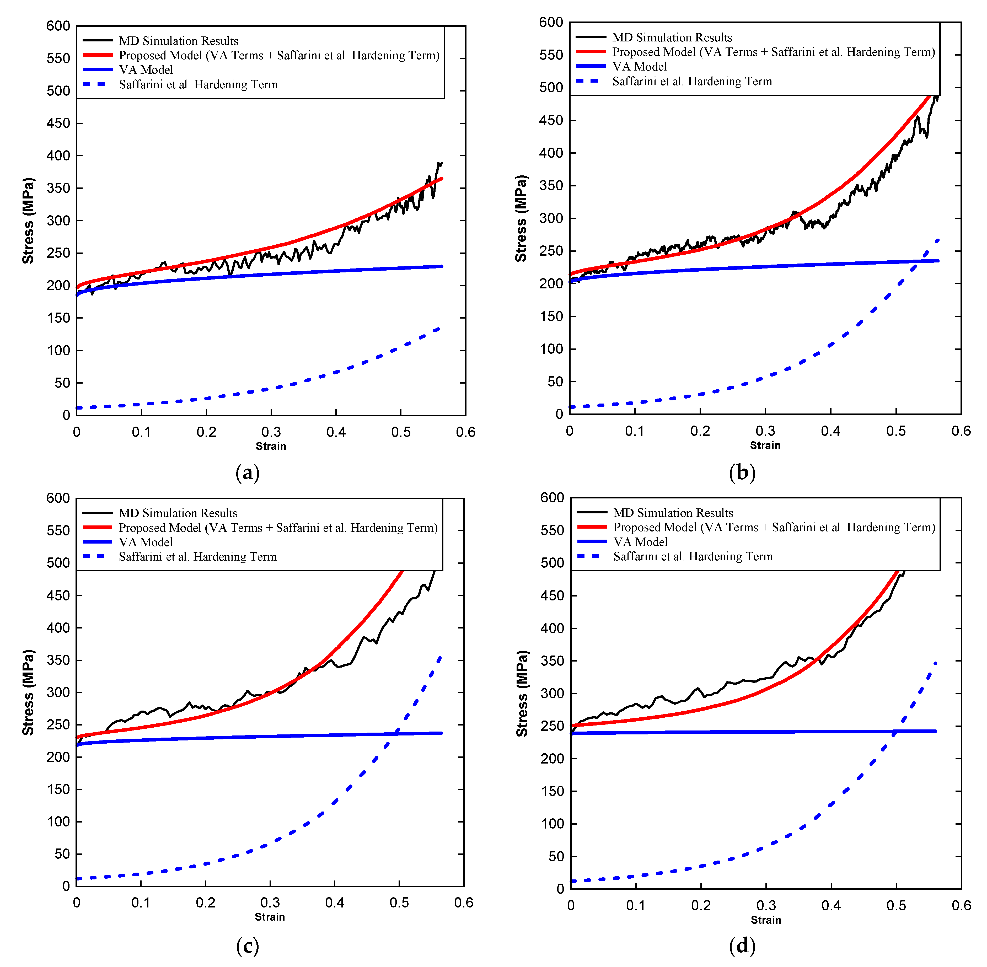
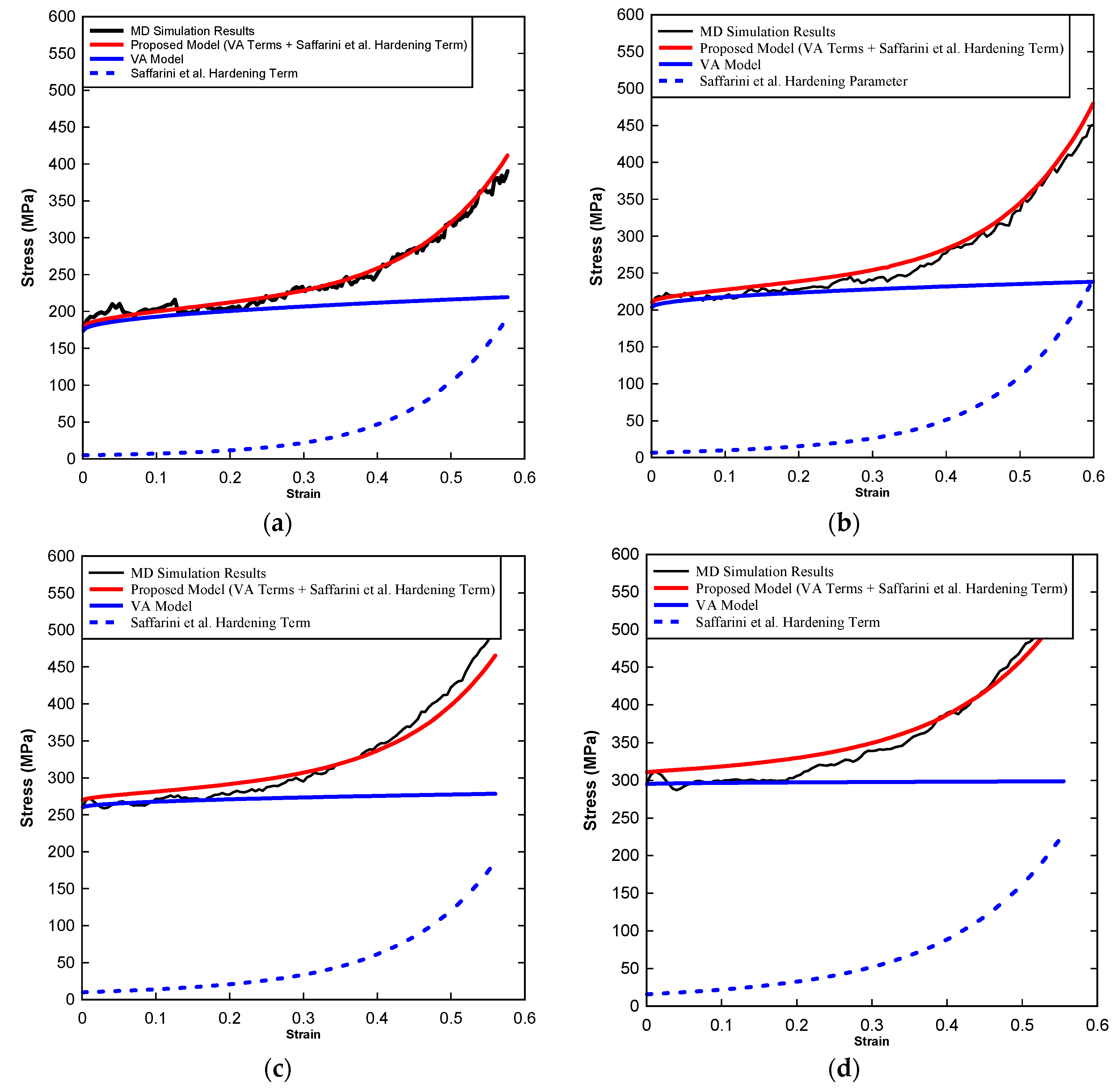
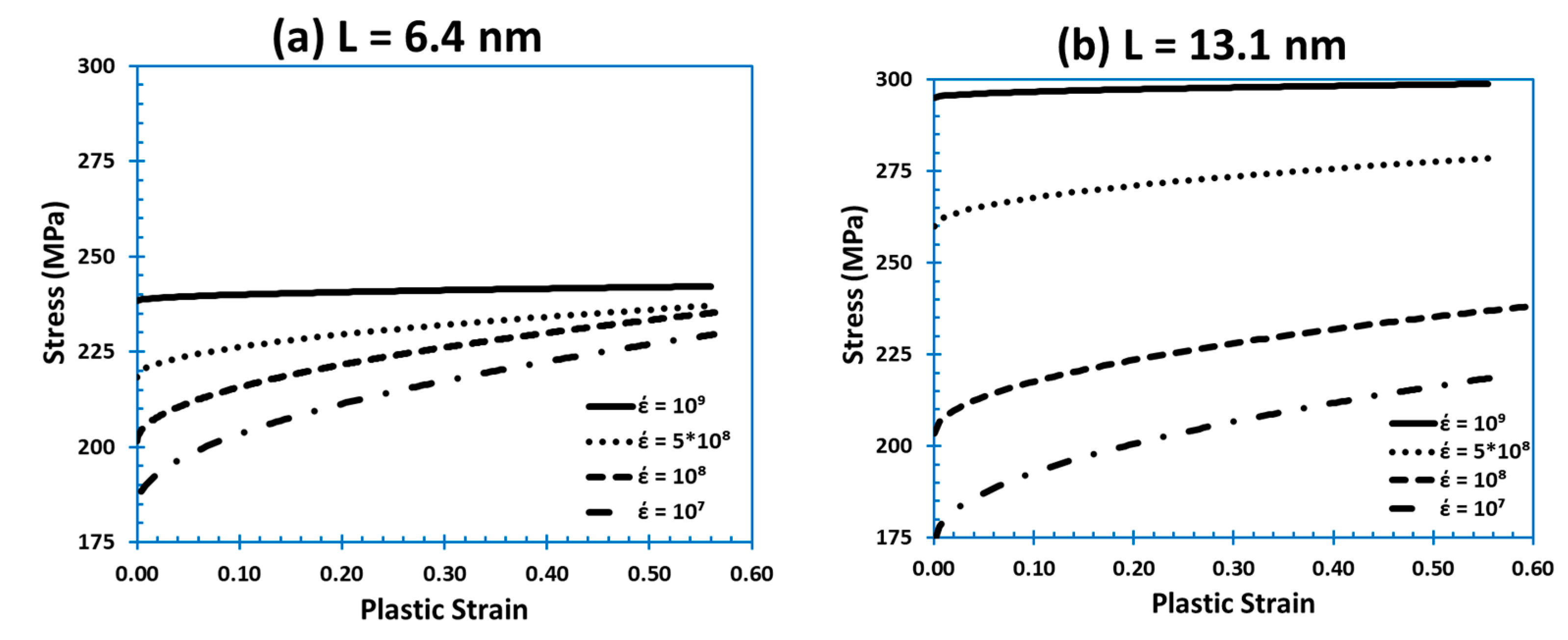
Figure 2 shows the proposed constitutive model predictions of the plastic flow in gold foam compared to the MD simulation results, the prediction of the VA constitutive model, and the predictions of the hardening term from the Saffarini et al. model (dislocation-controlled stress component) at different strain rates of , , , and for the smaller sample (). Figure 3 shows the same but for the larger sample ( = 13.1 nm). Figure 4 shows a comparison of the stress component corresponding to the VA model contribution to the newly proposed model due to thermal activation processes at the different strain rates of , , , and for both sizes simulated in this work ( and )
Several observations regarding the constitutive model behavior can be noted from the three figures. The first observation is that the proposed equation results are in good agreement with the MD simulation results. The proposed equation captures both the initial plateau-like plasticity and the later stages of densification, which are controlled mainly by the rapid increase in dislocation evolution upon porosity annihilation. As shown by Equation (10), the proposed equation is simply the sum of the VA part and the Saffarini et al. hardening part. For this, it is obvious that each component fails to capture the full stress–strain response of the material. Here appears the superiority of the atomistic-continuum constitutive model over the standalone continuum constitutive model. It is also obvious that the hardening term is not supposed to capture the MD simulation stress–strain response because it is only half the original model shown in Equation (1). However, it is important to highlight that the hardening stress component of the model comprises less than 15% of the total stress throughout the deformation process. The remaining 85% contribution comes from the VA stress component. In the previous atomistic formulation, the VA constitutive model was replaced by a simple multiplication between a constant and the yield stress. Although it phenomenologically captured the VA constitutive model contribution, that term did not have a physical reasoning behind it. Using the VA constitutive model, one can simply show that this term is physically justified.
Moreover, the previous atomistic formulation assumes that the yield-controlled stress term (refer to Equation (1)) is a constant value throughout the deformation process at each strain rate. That is simply because the constant parameter (C) is independent of the plastic strain or relative density. This means that for any strain rate, the yield-controlled stress component is a fixed value from plasticity initiation until complete densification. Despite it being true for a very high strain rate, it is not quite accurate for lower values of strain rate. As shown by Figure 4, the VA stress component shows that there is slight hardening due to thermal activation energy. This is more accurate constitutive description in light of the discussion in Section 4 where it shows that thermal activation processes still contribute to the material hardening even at high strain rates [47,50]. This shows that the updated model proposed in Equation (10) is better than that in Equation (1).
Another observation is that at very high strain rate, the VA component of Equation (10) reaches a value equal to the yield stress and maintains this value to be constant throughout the full deformation process. That behavior, which reaches the value of the yield stress or the athermal stress component of the VA constitutive model, can be noticed for both sizes at strain rate of in Figure 4a,b. This means that at very high strain rates, the contribution of the thermal activation part of the model towards the plastic deformation of the foam is becoming completely ineffective, and that the plastic flow is completely controlled by the hardening stress component (especially after densification initiation at ). This follows the discussion presented earlier in Section 4, in which it was shown that the contribution of the thermal activation processes decay and that the control will be mainly due to dislocation drag at very high strain rate, during which the dislocation evolution and speed become significantly high. In fact, those physical phenomena go hand to hand with the dislocation dynamics presented in the authors’ previous work about the effect of strain rate in gold foams at a wide range of strain rates [30].
The last observation is that in the case of the small sample, the hardening term contribution in the regions of material densification () increases significantly until it reaches or surpasses the value predicted by the VA stress component. This happens at later stages of the deformation when the material completely compresses and the porosity vanishes, transforming it from an open-cell bicontinuous foam microstructure into a full-density nonporous-like microstructure. At this stage the contribution of the upturn stress component matches the contribution of the VA stress component because the material is now fully populated by forest dislocations, and there is no dislocation annihilation at free surface anymore.
7. Conclusions
In this work, the authors performed large-scale simulations at wide range of strain rates ( to ) and different ligament sizes ( and ) to propose a new constitutive description of the plastic flow in gold foams. The description is based on an atomistic-continuum connection that physically captures both thermal activation processes at low strain rates as well as the upturn in flow stress controlled by dislocation drag and the rapid increase in their evolution at very high strain rates. The paper presents an overview of the theory behind the two combined models (atomistic constitutive model and the continuum constitutive model) to later introduce the connection between the two scales, and in turn, present the proposed model results. The proposed constitutive model shows good agreement with the simulation results and captures the physical description discussed throughout the paper. The model shows promising results in capturing the physics of the deformation mechanism in gold foams at a wide range of strain rates and for different sizes. The proposed equation captures both the initial plateau-like plasticity and the later stages of densification, which is controlled mainly by the rapid increase in dislocation evolution upon porosity annihilation. Moreover, it is observed that the proposed constitutive description is more accurate than the standalone VA model or the hardening term from the Saffarini et al. model. This comes from the fact that the model combines the best of the two models to cover all the processes involved in controlling the dislocation density effect (thermal activation energy and dislocation drag). Such a promising constitutive description can help improving integrated physics-based and AI-enabled design of architected metallic foams that deliver tailored mechanical responses at different scales.
Author Contributions
M.H.S., conceptualization, methodology, software, validation, formal analysis, investigation, data curation, writing—original draft, writing—review and editing, visualization, and funding acquisition; G.Z.V., conceptualization, methodology, software, validation, formal analysis, investigation, data curation, writing—original draft, writing—review and editing, visualization, supervision, project administration and funding acquisition. All authors have read and agreed to the published version of the manuscript.
Funding
This research received no external funding.
Data Availability Statement
The raw/processed data required to reproduce these findings is available from the authors upon reasonable request.
Acknowledgments
The authors wish to acknowledge that portions of this research were conducted with high performance computational resources provided by the Louisiana Optical Network Infrastructure (http://www.loni.org). Additionally, the authors would like to acknowledge the contribution of Carlos Ruestes for his input and feedback on the preparation of the samples and the simulation’s scripts.
Conflicts of Interest
The authors declare that they have no known competing financial interests or personal relationships that could have appeared to influence the work reported in this paper.
References
- Ashby, M.F.; Evans, T.; Fleck, N.A.; Gibson, L.J.; Hutchinson, J.W.; Wadley, H.N.G. Metal foams: A design guide. Mater. Des. 2002, 23, 119. [Google Scholar] [CrossRef]
- Gibson, L.J. Cellular Solids. MRS Bull. 2003, 28, 270–274. [Google Scholar] [CrossRef] [Green Version]
- Zhang, J.; Guo, H. Large deflection of rectangular sandwich tubes with metal foam core. Compos. Struct. 2022, 293, 115745. [Google Scholar] [CrossRef]
- Zhang, J.; Ye, Y.; Zhu, Y.; Yuan, H.; Qin, Q.; Wang, T. On axial splitting and curling behaviour of circular sandwich metal tubes with metal foam core. Int. J. Solids Struct. 2020, 202, 111–125. [Google Scholar] [CrossRef]
- Wittstock, A.; Biener, J.; Bäumer, M. Nanoporous gold: A new material for catalytic and sensor applications. Phys. Chem. Chem. Phys. 2010, 12, 12919–12930. [Google Scholar] [CrossRef]
- Biener, J.; Biener, M.M.; Madix, R.J.; Friend, C.M. Nanoporous Gold: Understanding the Origin of the Reactivity of a 21st Century Catalyst Made by Pre-Columbian Technology. ACS Catal. 2015, 5, 6263–6270. [Google Scholar] [CrossRef]
- Zielasek, V.; Jürgens, B.; Schulz, C.; Biener, J.; Biener, M.M.; Hamza, A.V.; Baeumer, M. Gold Catalysts: Nanoporous Gold Foams. Angew. Chem. Int. Ed. 2006, 45, 8241–8244. [Google Scholar] [CrossRef]
- Yogeswaran, U.; Chen, S.-M. A Review on the Electrochemical Sensors and Biosensors Composed of Nanowires as Sensing Material. Sensors 2008, 8, 290–313. [Google Scholar] [CrossRef] [Green Version]
- Xiao, X.; Si, P.; Magner, E. An overview of dealloyed nanoporous gold in bioelectrochemistry. Bioelectrochemistry 2016, 109, 117–126. [Google Scholar] [CrossRef]
- Lang, X.; Hirata, A.; Fujita, T.; Chen, M. Nanoporous metal/oxide hybrid electrodes for electrochemical supercapacitors. Nat. Nanotechnol. 2011, 6, 232–236. [Google Scholar] [CrossRef]
- Hou, Y.; Chen, L.; Hirata, A.; Fujita, T.; Chen, M. Non-aqueous nanoporous gold based supercapacitors with high specific energy. Scr. Mater. 2016, 116, 76–81. [Google Scholar] [CrossRef] [Green Version]
- Quynh, B.T.P.; Byun, J.Y.; Kim, S.H. Non-enzymatic amperometric detection of phenol and catechol using nanoporous gold. Sens. Actuators B Chem. 2015, 221, 191–200. [Google Scholar] [CrossRef]
- Biener, J.; Wittstock, A.; Zepeda-Ruiz, L.A.; Biener, M.M.; Zielasek, V.; Kramer, D.; Viswanath, R.N.; Weissmüller, J.; Bäumer, M.; Hamza, A.V. Surface-chemistry-driven actuation in nanoporous gold. Nat. Mater. 2009, 8, 47–51. [Google Scholar] [CrossRef] [PubMed]
- Bringa, E.; Monk, J.D.; Caro, A.; Misra, A.; Zepeda-Ruiz, L.; Duchaineau, M.; Abraham, F.; Nastasi, M.; Picraux, S.T.; Wang, Y.Q.; et al. Are Nanoporous Materials Radiation Resistant? Nano Lett. 2012, 12, 3351–3355. [Google Scholar] [CrossRef] [PubMed]
- Caro, M.; Mook, W.M.; Fu, E.G.; Wang, Y.Q.; Sheehan, C.; Martinez, E.; Baldwin, J.K.; Caro, A. Radiation induced effects on mechanical properties of nanoporous gold foams. Appl. Phys. Lett. 2014, 104, 233109. [Google Scholar] [CrossRef]
- Ruestes, C.J.; Anders, C.; Bringa, E.M.; Urbassek, H.M. Nanoindentation tests of heavy-ion-irradiated Au foams—Molecular dynamics simulation. J. Appl. Phys. 2018, 123, 225903. [Google Scholar] [CrossRef]
- Hodge, A.M.; Hayes, J.R.; Caro, J.A.; Biener, J.; Hamza, A.V. Characterization and Mechanical Behavior of Nanoporous Gold. Adv. Eng. Mater. 2006, 8, 853–857. [Google Scholar] [CrossRef]
- Hodge, A.M.; Biener, J.; Hayes, J.R.; Bythrow, P.M.; Volkert, C.A.; Hamza, A.V. Scaling equation for yield strength of nanoporous open-cell foams. Acta Mater. 2007, 55, 1343–1349. [Google Scholar] [CrossRef] [Green Version]
- Mathur, A.; Erlebacher, J. Size dependence of effective Young’s modulus of nanoporous gold. Appl. Phys. Lett. 2007, 90, 061910. [Google Scholar] [CrossRef]
- Hakamada, M.; Mabuchi, M. Mechanical strength of nanoporous gold fabricated by dealloying. Scr. Mater. 2007, 56, 1003–1006. [Google Scholar] [CrossRef]
- Briot, N.J.; Kennerknecht, T.; Eberl, C.; Balk, T.J. Mechanical properties of bulk single crystalline nanoporous gold investigated by millimetre-scale tension and compression testing. Philos. Mag. 2014, 94, 847–866. [Google Scholar] [CrossRef]
- Bürckert, M.; Briot, N.J.; Balk, T.J. Uniaxial compression testing of bulk nanoporous gold. Philos. Mag. 2017, 97, 1157–1178. [Google Scholar] [CrossRef]
- Pia, G.; Carta, M.; Delogu, F. Nanoporous Au foams: Variation of effective Young’s modulus with ligament size. Scr. Mater. 2018, 144, 22–26. [Google Scholar] [CrossRef]
- Sun, X.-Y.; Xu, G.-K.; Li, X.; Feng, X.-Q.; Gao, H. Mechanical properties and scaling laws of nanoporous gold. J. Appl. Phys. 2013, 113, 023505. [Google Scholar] [CrossRef]
- Farkas, D.; Caro, A.; Bringa, E.; Crowson, D. Mechanical response of nanoporous gold. Acta Mater. 2013, 61, 3249–3256. [Google Scholar] [CrossRef]
- Beets, N.; Farkas, D.; Corcoran, S. Deformation mechanisms and scaling relations in the mechanical response of nano-porous Au. Acta Mater. 2019, 165, 626–637. [Google Scholar] [CrossRef]
- Giri, A.; Tao, J.; Wang, L.; Kirca, M.; To, A.C. Compressive Behavior and Deformation Mechanism of Nanoporous Open-Cell Foam with Ultrathin Ligaments. J. Nanomech. Micromech. 2014, 4, A4013012. [Google Scholar] [CrossRef]
- Jiao, J.; Huber, N. Deformation mechanisms in nanoporous metals: Effect of ligament shape and disorder. Comput. Mater. Sci. 2017, 127, 194–203. [Google Scholar] [CrossRef] [Green Version]
- Saffarini, M.H.; Voyiadjis, G.Z.; Ruestes, C.J. Temperature effect on nanoporous gold under uniaxial tension and compression. Comput. Mater. Sci. 2021, 200, 110766. [Google Scholar] [CrossRef]
- Voyiadjis, G.Z.; Saffarini, M.H.; Ruestes, C.J. Characterization of the Strain Rate Effect under Uniaxial Loading for Nanoporous Gold George. Comput. Mater. Sci. 2021, 194, 110425. [Google Scholar] [CrossRef]
- Saffarini, M.H.; Voyiadjis, G.Z.; Ruestes, C.J.; Yaghoobi, M. Ligament size dependency of strain hardening and ductility in nanoporous gold. Comput. Mater. Sci. 2021, 186, 109920. [Google Scholar] [CrossRef]
- Biener, J.; Hodge, A.M.; Hayes, J.R.; Volkert, C.A.; Zepeda-Ruiz, L.A.; Hamza, A.V.; Abraham, F.F. Size Effects on the Mechanical Behavior of Nanoporous Au. Nano Lett. 2006, 6, 2379–2382. [Google Scholar] [CrossRef]
- Lührs, L.; Soyarslan, C.; Markmann, J.; Bargmann, S.; Weissmüller, J. Elastic and plastic Poisson’s ratios of nanoporous gold. Scr. Mater. 2016, 110, 65–69. [Google Scholar] [CrossRef] [Green Version]
- Badwe, N.; Chen, X.; Sieradzki, K. Mechanical properties of nanoporous gold in tension. Acta Mater. 2017, 129, 251–258. [Google Scholar] [CrossRef] [Green Version]
- Lührs, L.; Zandersons, B.; Huber, N.; Weissmüller, J. Plastic Poisson’s Ratio of Nanoporous Metals: A Macroscopic Signature of Tension–Compression Asymmetry at the Nanoscale. Nano Lett. 2017, 17, 6258–6266. [Google Scholar] [CrossRef] [Green Version]
- Chaboche, J.L. A review of some plasticity and viscoplasticity constitutive theories. Int. J. Plast. 2008, 24, 1642–1693. [Google Scholar] [CrossRef]
- Gao, C.Y.; Zhang, L.C. Constitutive modelling of plasticity of fcc metals under extremely high strain rates. Int. J. Plast. 2012, 32, 121–133. [Google Scholar] [CrossRef]
- Huang, M.; Rivera-Díaz-Del-Castillo, P.E.; Bouaziz, O.; Van der Zwaag, S. A constitutive model for high strain rate deformation in FCC metals based on irreversible thermodynamics. Mech. Mater. 2009, 41, 982–988. [Google Scholar] [CrossRef]
- Xu, Z.; Huang, F. Comparison of constitutive models for FCC metals over wide temperature and strain rate ranges with application to pure copper. Int. J. Impact Eng. 2015, 79, 65–74. [Google Scholar] [CrossRef]
- Liang, R.; Khan, A.S. A critical review of experimental results and constitutive models for BCC and FCC metals over a wide range of strain rates and temperatures. Int. J. Plast. 1999, 15, 963–980. [Google Scholar] [CrossRef]
- Jin, H.-J.; Weissmüller, J.; Farkas, D. Mechanical response of nanoporous metals: A story of size, surface stress, and severed struts. MRS Bull. 2018, 43, 35–42. [Google Scholar] [CrossRef]
- Ruestes, C.J.; Farkas, D.; Caro, A.; Bringa, E.M. Hardening under compression in Au foams. Acta Mater. 2016, 108, 1–7. [Google Scholar] [CrossRef]
- Ruestes, C.J.; Schwen, D.; Millán, E.N.; Aparicio, E.; Bringa, E.M. Mechanical properties of Au foams under nanoindentation. Comput. Mater. Sci. 2018, 147, 154–167. [Google Scholar] [CrossRef]
- Austin, R.A.; McDowell, D.L. A dislocation-based constitutive model for viscoplastic deformation of fcc metals at very high strain rates. Int. J. Plast. 2011, 27, 1–24. [Google Scholar] [CrossRef]
- Preston, D.L.; Tonks, D.L.; Wallace, D.C. Model of plastic deformation for extreme loading conditions. J. Appl. Phys. 2003, 93, 211–220. [Google Scholar] [CrossRef] [Green Version]
- Hansen, B.L.; Beyerlein, I.J.; Bronkhorst, C.A.; Cerreta, E.K.; Dennis-Koller, D. A dislocation-based multi-rate single crystal plasticity model. Int. J. Plast. 2013, 44, 129–146. [Google Scholar] [CrossRef]
- Zerilli, F.J.; Armstrong, R.W. Dislocation-mechanics-based constitutive relations for material dynamics calculations. J. Appl. Phys. 1987, 61, 1816–1825. [Google Scholar] [CrossRef] [Green Version]
- Rodríguez-Martínez, J.; Rodríguez-Millán, M.; Rusinek, A.; Arias, A. A dislocation-based constitutive description for modeling the behavior of FCC metals within wide ranges of strain rate and temperature. Mech. Mater. 2011, 43, 901–912. [Google Scholar] [CrossRef] [Green Version]
- Voyiadjis, G.Z.; Abed, F.H. Microstructural based models for bcc and fcc metals with temperature and strain rate dependency. Mech. Mater. 2005, 37, 355–378. [Google Scholar] [CrossRef]
- Follansbee, P.S.; Kocks, U.F. A constitutive description of the deformation of copper based on the use of the mechanical threshold stress as an internal state variable. Acta Metall. 1988, 36, 81–93. [Google Scholar] [CrossRef] [Green Version]
- Fang, H.; Bi, J.; Zhang, C.; Gutowski, M.; Palta, E.; Wang, Q. A constitutive model of aluminum foam for crash simulations. Int. J. Non-Linear Mech. 2017, 90, 124–136. [Google Scholar] [CrossRef]
- Wang, Z.-H.; Jing, L.; Zhao, L.-M. Elasto-plastic constitutive model of aluminum alloy foam subjected to impact loading. Trans. Nonferrous Met. Soc. China 2011, 21, 449–454. [Google Scholar] [CrossRef]
- Reyes, A.; Hopperstad, O.S.; Berstad, T.; Hanssen, A.; Langseth, M. Constitutive modeling of aluminum foam including fracture and statistical variation of density. Eur. J. Mech.—A/Solids 2003, 22, 815–835. [Google Scholar] [CrossRef]
- Chang, F.S.; Song, Y.; Lu, D.X.; DeSilva, C.N. Unified Constitutive Equations of Foam Materials. J. Eng. Mater. Technol. 1998, 120, 212–217. [Google Scholar] [CrossRef]
- Af Segerstad, P.H.; Larsson, R.; Toll, S. A constitutive equation for open-cell cellular solids, including viscoplasticity, damage and deformation induced anisotropy. Int. J. Plast. 2008, 24, 896–914. [Google Scholar] [CrossRef]
- Af Segerstad, P.H.; Toll, S. Open-cell cellular solids: A constitutive equation for hyperelasticity with deformation induced anisotropy. Int. J. Solids Struct. 2008, 45, 1978–1992. [Google Scholar] [CrossRef] [Green Version]
- Voyiadjis, G.Z.; Abed, F.H. Effect of dislocation density evolution on the thermomechanical response of metals with different crystal structures at low and high strain rates and temperatures. Arch. Mech. 2005, 57, 299–343. [Google Scholar] [CrossRef]
- Saffarini, M.H.; Voyiadjis, G.Z.; Ruestes, C.J. Scaling laws for nanoporous metals under uniaxial loading. J. Mater. Res. 2021, 36, 2729–2741. [Google Scholar] [CrossRef]
- Hull, D.; Bacon, D. Introduction to Dislocations; Butterworth-Heinemann: Oxford, UK, 2011. [Google Scholar]
- Steinberg, D.J.; Lund, C.M. A constitutive model for strain rates from 10−4to 106s−1. J. Appl. Phys. 1988, 49, C3-433. [Google Scholar] [CrossRef]
- Rusinek, A.; Rodríguez-Martínez, J.; Arias, A. A thermo-viscoplastic constitutive model for FCC metals with application to OFHC copper. Int. J. Mech. Sci. 2010, 52, 120–135. [Google Scholar] [CrossRef] [Green Version]
- Zerilli, F.J.; Armstrong, R.W. The effect of dislocation drag on the stress-strain behavior of F.C.C. metals. Acta Met. Mater. 1992, 40, 1803–1808. [Google Scholar] [CrossRef]
- Blaschke, D.N.; Burakovsky, L.; Preston, D.L. On the temperature and density dependence of dislocation drag from phonon wind. J. Appl. Phys. 2021, 130, 015901. [Google Scholar] [CrossRef]
- Nemat-Nasser, S.; Li, Y. Flow stress of f.c.c. polycrystals with application to OFHC Cu. Acta Mater. 1998, 46, 565–577. [Google Scholar] [CrossRef]
- Molinari, A.; Ravichandran, G. Constitutive modeling of high-strain-rate deformation in metals based on the evolution of an effective microstructural length. Mech. Mater. 2005, 37, 737–752. [Google Scholar] [CrossRef]
- Klepaczko, J.R.; Chiem, C.Y. On rate sensitivity of f.c.c. metals, instantaneous rate sensitivity and rate sensitivity of strain hardening. J. Mech. Phys. Solids 1986, 34, 29–54. [Google Scholar] [CrossRef]
- Klepaczko, J.R. Physical-state variables—The key to constitutive modeling in dynamic plasticity. Nucl. Eng. Des. 1991, 127, 103–115. [Google Scholar] [CrossRef]
- Kubin, L.P.; Estrin, Y. Evolution of dislocation densities and the critical conditions for the Portevin-Le Châtelier effect. Acta Met. Mater. 1990, 38, 697–708. [Google Scholar] [CrossRef]
- Voyiadjis, G.Z.; Almasri, A.H. A physically based constitutive model for fcc metals with applications to dynamic hardness. Mech. Mater. 2008, 40, 549–563. [Google Scholar] [CrossRef]
- Armstrong, R.W.; Ramachandran, V.; Zerilli, F.J. Materials for Advanced Technology System. In Indian Institute of Metals Symposium; Indian Institute of Metals: New Delhi, India, 1993. [Google Scholar]
- Saffarini, M.H.Y. Atomistic Thermo-Mechanical Description of the Deformation Behavior, Scaling Laws, and Constitutive Modeling of Nanoporous Gold. 2021. Available online: https://digitalcommons.lsu.edu/gradschool_dissertations/5568 (accessed on 5 January 2023).
- Crowson, D.A.; Farkas, D.; Corcoran, S.G. Mechanical stability of nanoporous metals with small ligament sizes. Scr. Mater. 2009, 61, 497–499. [Google Scholar] [CrossRef]
- Crowson, D.A.; Farkas, D.; Corcoran, S.G. Geometric relaxation of nanoporous metals: The role of surface relaxation. Scr. Mater. 2007, 56, 919–922. [Google Scholar] [CrossRef]
- Newman, R.C.; Corcoran, S.G.; Erlebacher, J.; Aziz, M.J.; Sieradzki, K. Alloy Corrosion. MRS Bull. 1999, 24, 24–28. [Google Scholar] [CrossRef]
- Stuckner, J.; Frei, K.; McCue, I.; Demkowicz, M.J.; Murayama, M. AQUAMI: An open source Python package and GUI for the automatic quantitative analysis of morphologically complex multiphase materials. Comput. Mater. Sci. 2017, 139, 320–329. [Google Scholar] [CrossRef]
- Plimpton, S. Fast Parallel Algorithms for Short-Range Molecular Dynamics. J. Comput. Phys. 1995, 117, 1–19. [Google Scholar] [CrossRef] [Green Version]
- Foiles, S.M.; Baskes, M.I.; Daw, M.S. Embedded-atom-method functions for the fcc metals Cu, Ag, Au, Ni, Pd, Pt, and their alloys. Phys. Rev. B 1986, 33, 7983–7991. [Google Scholar] [CrossRef]
- Stukowski, A.; Bulatov, V.V.; Arsenlis, A. Automated identification and indexing of dislocations in crystal interfaces. Model. Simul. Mater. Sci. Eng. 2012, 20, 085007. [Google Scholar] [CrossRef]
- Stukowski, A. Computational Analysis Methods in Atomistic Modeling of Crystals. Jom 2014, 66, 399–407. [Google Scholar] [CrossRef]
- Stukowski, A.; Albe, K. Extracting dislocations and non-dislocation crystal defects from atomistic simulation data. Model. Simul. Mater. Sci. Eng. 2010, 18, 085001. [Google Scholar] [CrossRef]
- Stukowski, A. Structure identification methods for atomistic simulations of crystalline materials. Model. Simul. Mater. Sci. Eng. 2012, 20, 045021. [Google Scholar] [CrossRef] [Green Version]
- Stukowski, A. Visualization and analysis of atomistic simulation data with OVITO—The Open Visualization Tool. Model. Simul. Mater. Sci. Eng. 2009, 18, 015012. [Google Scholar] [CrossRef]
- Thompson, A.P.; Plimpton, S.J.; Mattson, W. General formulation of pressure and stress tensor for arbitrary many-body interaction potentials under periodic boundary conditions. J. Chem. Phys. 2009, 131, 154107. [Google Scholar] [CrossRef] [Green Version]
Figure 1.
The small sample microstructure and morphology. This template was scaled as is to produce the larger sample which ended up having same porosity and network connectivity, but with different ligament size (solid surface is white and interior of solid is gold).
Figure 1.
The small sample microstructure and morphology. This template was scaled as is to produce the larger sample which ended up having same porosity and network connectivity, but with different ligament size (solid surface is white and interior of solid is gold).

Figure 2.
Model predictions of the plastic flow in gold foam compared to the MD simulation results performed in this work, the VA model predictions, and the hardening term from the Saffarini et al. model (dislocation-controlled stress component) in Equation (1) at (a) , (b) , (c) , (d) . All for the smaller sized sample with .

Figure 3.
Model predictions of the plastic flow in gold foam compared to the MD simulation results performed in this work, the VA model predictions, and the hardening term from the Saffarini et al. model (dislocation-controlled stress component) in Equation (1) at (a) , (b) , (c) , (d) . All for the medium-sized sample with .

Figure 4.
The stress component value corresponding to the VA model contribution of the newly proposed model due to thermal activation processes at , , , and for both sizes simulated in this work.
Figure 4.
The stress component value corresponding to the VA model contribution of the newly proposed model due to thermal activation processes at , , , and for both sizes simulated in this work.


Table 1.
Equation (1) parameters values according to Saffarini et al. [29].
Table 1.
Equation (1) parameters values according to Saffarini et al. [29].
| Avg. Ligament Diameter (nm) | 6.4 | 13.1 | 25.6 | |||||||||
|---|---|---|---|---|---|---|---|---|---|---|---|---|
| Temperature (K) | 300 | 300 | 400 | 500 | 600 | 700 | 300 | |||||
| Compression | C | 1.10 | 1.05 | 0.95 | ||||||||
| D (MPa) | 11 | 12 | 13 | 17.5 | 23 | 11 | 5.5 | 1.0 | ||||
| n (×10−12) (mm2) | 9.5 | 8.2 | 7.5 | 7.0 | 10.5 | 23.5 | ||||||
Table 2.
Equation (2) parameters values according to Saffarini et al. [29].
Table 2.
Equation (2) parameters values according to Saffarini et al. [29].
| Avg. Ligament Diameter (nm) | 6.4 | 13.1 | 25.6 | |||||||||
|---|---|---|---|---|---|---|---|---|---|---|---|---|
| Temperature (K) | 300 | 300 | 400 | 500 | 600 | 700 | 300 | |||||
| Comp | A (×1017) | −27.5 | −33 | −42 | −38.5 | −35 | −31.5 | −23.5 | −45 | −22.62 | −16.56 | |
| B (×1017) | 4 | 4.7 | 5.9 | 5.4 | 5 | 4.5 | 3.5 | 6.4 | 8.6 | 8.2 | ||
| m | −4 | −2 | −1.42 | |||||||||
Table 3.
Equation (8) parameter values.
| (nm) | 6.4 | 13.1 | ||||||
|---|---|---|---|---|---|---|---|---|
| (×) () | 4.7 | 5.9 | 6.4 | 6.4 | 8.85 | 8.6 | 8 | 7.75 |
| (×) () | −33 | −42 | −45 | −45 | −24.2 | −22.62 | −20 | −18 |
| −4 | −2 | |||||||
Table 4.
Equation (10) parameter values.
| 6.4 | 13.1 | |||||||
|---|---|---|---|---|---|---|---|---|
| (MPa) | 180 | 200 | 220 | 240 | 170 | 200 | 250 | 290 |
| (MPa) | 1000 | |||||||
| 0.003315 | 0.003323 | 0.003330 | 0.003333 | 0.003315 | 0.003323 | 0.003330 | 0.003333 | |
| (MPa) | 50 | |||||||
| 0.5 | ||||||||
| 1.5 | ||||||||
| (MPa) | 11 | 5.5 | ||||||
| (×) () | 7.5 | 9.5 | ||||||
Disclaimer/Publisher’s Note: The statements, opinions and data contained in all publications are solely those of the individual author(s) and contributor(s) and not of MDPI and/or the editor(s). MDPI and/or the editor(s) disclaim responsibility for any injury to people or property resulting from any ideas, methods, instructions or products referred to in the content. |
© 2023 by the authors. Licensee MDPI, Basel, Switzerland. This article is an open access article distributed under the terms and conditions of the Creative Commons Attribution (CC BY) license (https://creativecommons.org/licenses/by/4.0/).
Share and Cite
MDPI and ACS Style
Saffarini, M.H.; Voyiadjis, G.Z. Atomistic-Continuum Constitutive Modeling Connection for Gold Foams under Compression at High Strain Rates: The Dislocation Density Effect. Metals 2023, 13, 652. https://doi.org/10.3390/met13040652
AMA Style
Saffarini MH, Voyiadjis GZ. Atomistic-Continuum Constitutive Modeling Connection for Gold Foams under Compression at High Strain Rates: The Dislocation Density Effect. Metals. 2023; 13(4):652. https://doi.org/10.3390/met13040652
Chicago/Turabian StyleSaffarini, Mohammed H., and George Z. Voyiadjis. 2023. "Atomistic-Continuum Constitutive Modeling Connection for Gold Foams under Compression at High Strain Rates: The Dislocation Density Effect" Metals 13, no. 4: 652. https://doi.org/10.3390/met13040652
Note that from the first issue of 2016, this journal uses article numbers instead of page numbers. See further details here.