
A Critical Review on Fiber Metal Laminates (FML): From Manufacturing to Sustainable Processing
by
 , , and
Rúben D. F. S. Costa
1,2,
Rita C. M. Sales-Contini
3 ,
,
Francisco J. G. Silva
2,4,*,
Naiara Sebbe
4 and
Abílio M. P. Jesus
1,2
1
FEUP, Faculty of Engineering, University of Porto, Rua Dr. Roberto Frias 400, 4200-465 Porto, Portugal
2
Associate Laboratory for Energy, Transports and Aerospace (LAETA-INEGI), Rua Dr. Roberto Frias 400, 4200-465 Porto, Portugal
3
Aeronautical Structures Laboratory, Faculdade de Tecnologia de São José dos Campos Prof. Jessen Vidal, Centro Paula Souza, São José dos Campos, 1350 Distrito Eugênio de Melo, São Paulo 12247-014, SP, Brazil
4
ISEP, Polytechnic of Porto, Rua Dr. António Bernardino de Almeida, 4249-015 Porto, Portugal
*
Author to whom correspondence should be addressed.
Metals 2023, 13(4), 638; https://doi.org/10.3390/met13040638
Submission received: 16 February 2023
/
Revised: 12 March 2023
/
Accepted: 17 March 2023
/
Published: 23 March 2023
(This article belongs to the Special Issue Machining: State-of-the-Art 2022)
Abstract
:Composite materials such as Fiber Metal Laminates (FMLs) have attracted the interest of the aerospace and automotive industries due to their high strength to weight ratio, but to use them as structures it is necessary to master the manufacturing and wiring techniques of these materials. Therefore, this paper aims to address and summarize the drilling and milling processes in FMLs based on a literature review of papers published from 2000 to 2023. Parameters used in multi-material manufacturing and machining such as drilling and milling, tool geometry, tool coating, lubricants and coolants published by researchers were analyzed, compared and discussed. Machining process parameters related to sustainability were also analyzed. A SWOT analysis was carried out and discussed to identify opportunities for improvement in the machining process. There are opportunities to develop the surface treatment of aluminum alloys, such as testing other combinations than those already used, testing non-traditional surface treatments and manufacturing modes, and developing sustainable techniques during the FML manufacturing process. In the area of tooling, the opportunities are mainly related to coatings for tools and changing machining parameters to achieve an optimum finished part. Finally, to improve the sustainability of the process, it is necessary to test coated drills under cryogenic conditions to reduce the use of lubricants during the machining process.
Keywords:
fiber metal laminate; drilling; milling; coolant; tool wear; tool geometry; sustainability1. Introduction
Composite materials have been gaining visibility for the last few decades due to their advanced properties in comparison to the other material families, specifically in the aeronautic industry, but also with a growing interest in the automobile industry. This tendency began after the Second World War with innovations for military applications, where these materials brought a significant weight reduction in structural design and presented excellent fatigue properties and corrosion resistance as well [1,2].
Fiber-reinforced polymers (FRPs) are heterogeneous composite materials which combine lightweight, stiff and brittle reinforcing fibers, such as aramid, glass and carbon (known, respectively, as AFRPs, GFRPs and CFRPs) bound together by a polymeric matrix (thermoplastic or thermoset) [2]. The fibers, the reinforcing phase, contribute to the improvement of the mechanical properties of the laminated composite, whereas the matrix transfers the load to the inner fibers and at the same time it protects them from external damage and provides the composite material with its high fracture toughness [3].
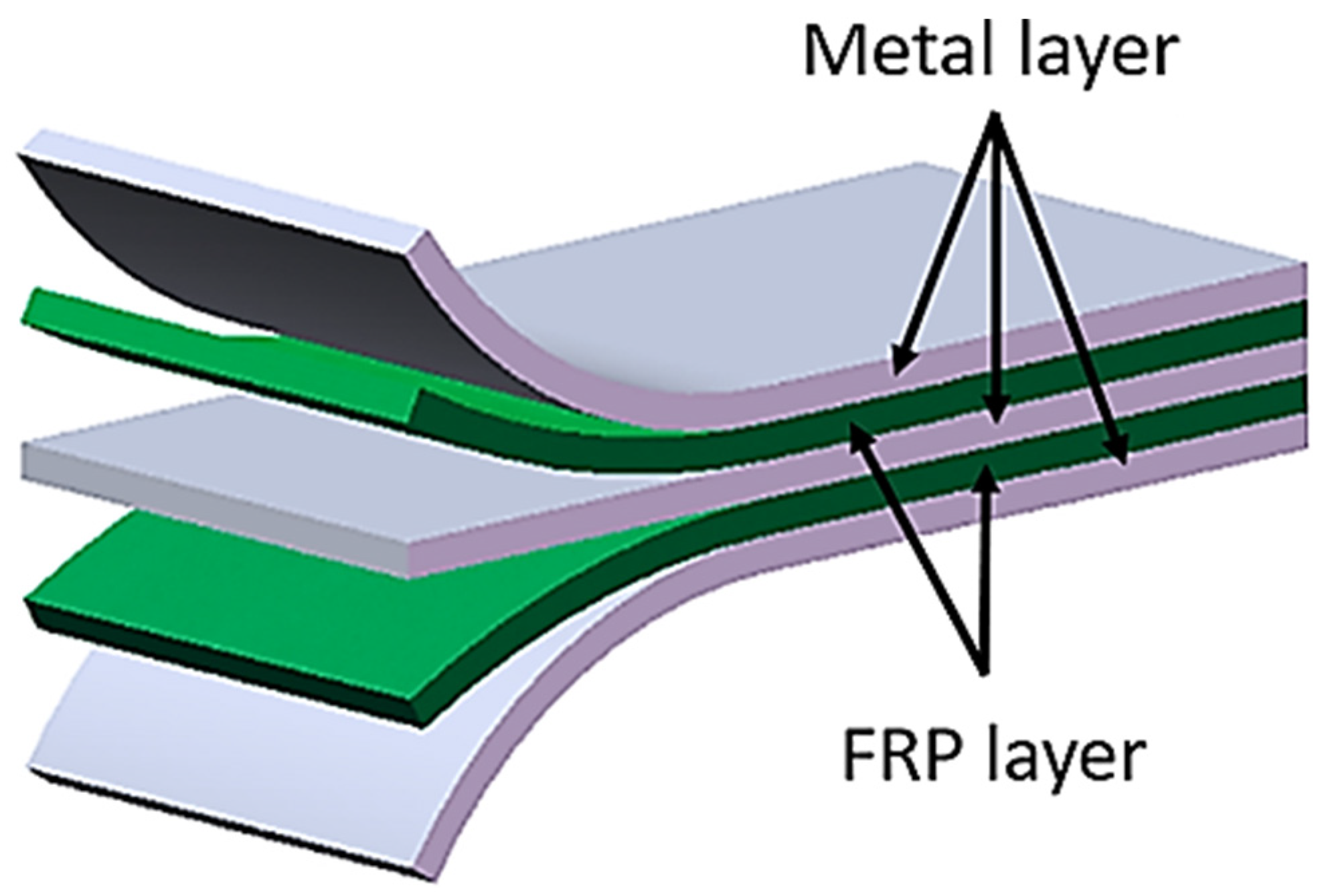
In spite of this, there was a need to improve even further the properties of these materials so they could sustain the harsher conditions existent in aircraft, a requisite satisfied with the appearance of the fiber-metal laminates (FMLs) [4]. These are, by definition, hybrid structures which combine alternate phases of FRPs in the form of plies with thin sheets of a metal alloy, usually aluminum (FRP/Al) or titanium (FRP/Ti) [5,6]. An example of a FML with the fibers incorporated in epoxy resin is observable in Figure 1, which presents a three/two lay-up, since three metal layers alternate with two reinforcement ones.
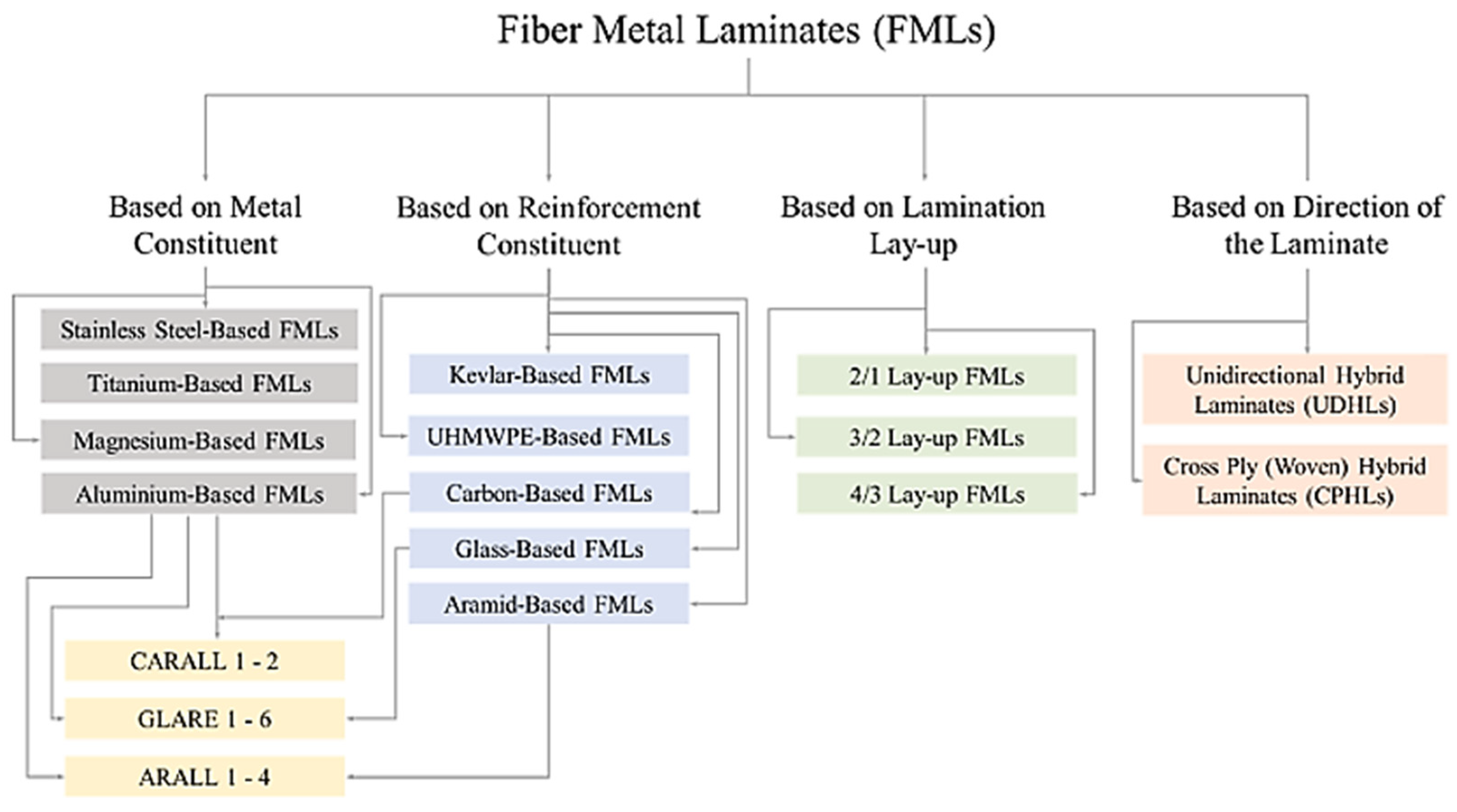
Nowadays, several types of FMLs exist, depending on the chosen metal to use or even the polymer, based on the intended application for the new material. For example, if these are composed of elastomer interlayers, their designation becomes FMEL, for fiber-metal-elastomer laminates [8]. On the other hand, considering just the metal counterpart, the most common FMLs are the CARALL (Carbon Reinforced Aluminum Laminate), GLARE (Glass Reinforced Aluminum Laminate) and ARALL (Aramid Reinforced Aluminum Laminate) [9,10,11,12]. Apart from the metal and reinforcement constituents, as well as the lay-up configuration in which the metal layers can be outside or inside the multi-material, the direction of the laminate must also be considered, namely, if it is a unidirectional hybrid laminate or a cross ply (woven), as shown in Figure 2.
Through this union, FMLs combine the durability and easiness of fabrication associated with metal alloys with the outstanding specific properties and excellent fracture and fatigue resistance of high-performance composite materials [14,15]. Furthermore, metals lack fatigue strength and corrosion resistance, whereas composites have a low bearing strength and impact strength, in addition to their problem of reparability [16]. Hence, the combination of both materials overcomes the existing negative issues individually. The result is a high-strength, lightweight material with improved thermal, mechanical and tribological properties [17].
Regarding the manufacturing of multi-materials, this is a difficult process, due to the different properties of the materials to be joined and relatively weak adhesion between them [18,19,20,21]. Surface treatments can also be executed to enhance the adhesion at the metal-composite interface [22,23,24,25]. An adequate surface treatment of the metallic layer is indispensable to guarantee a good mechanical and adhesive bond between the composite laminates and metal surfaces. This treatment can be mechanical, through an abrasion to produce a macro-roughened surface and to remove undesirable oxide layers; chemical, with the immersion of the substrate in an acid solution; or electrochemical, with a coupling agent or dry surface, such as plasma-sprayed coating or ion-beam-enhanced deposition [1]. After the treatment, metal sheets may also be annealed, in order to relieve mechanical and thermal stresses, another step to facilitate the adhesion [26].
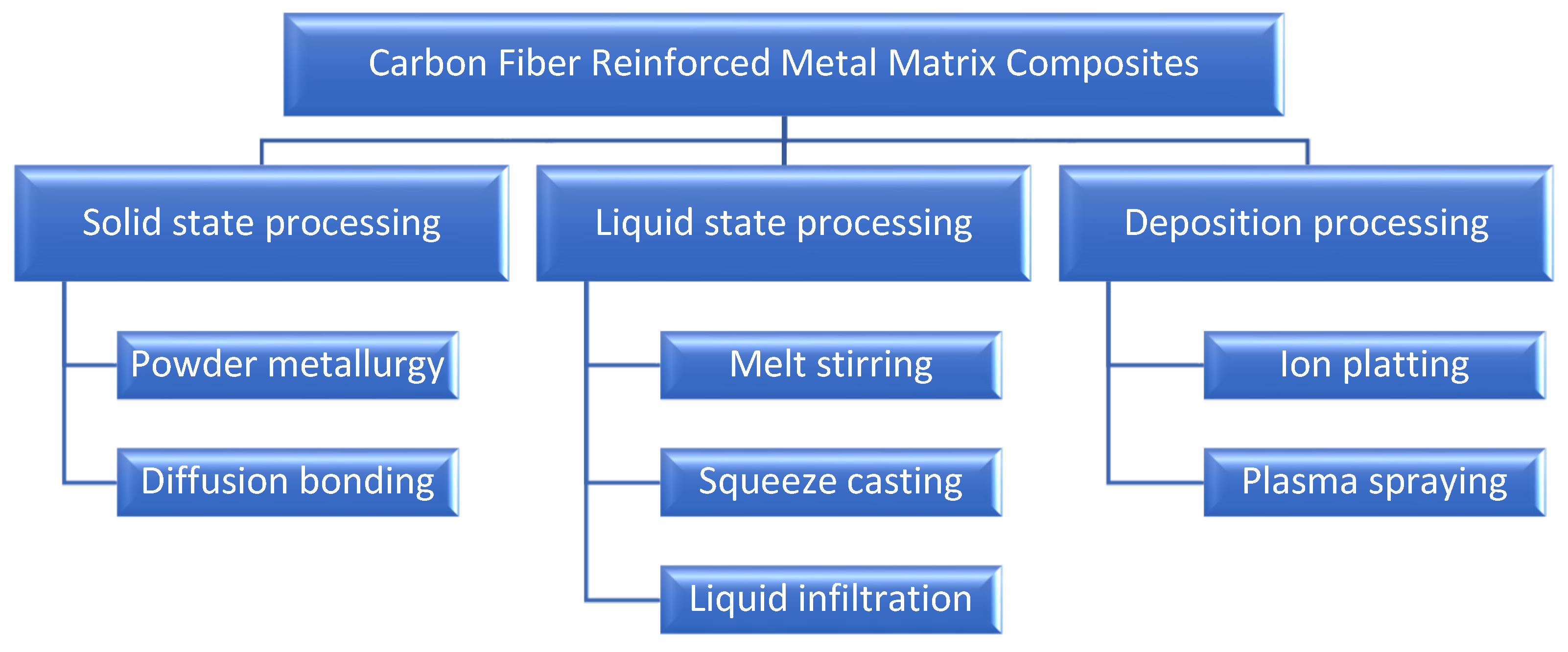
Several methods can be employed to achieve the intended configuration, with the most prominent being the fusion, chemical bonding (bond dual materials using structural adhesive) [27,28,29], physical and mechanical bonding, such as screwing or riveting (SPR) [21] and friction-based joining processes [30]. Figure 3 presents some of the processing methods used in the fabrication of Carbon Fiber Reinforced Metal Matrix Composites (CF/MMCs).
The shown techniques can be of diverse natures. In the solid-state processing, the composites are formed as a result of bonding between the metallic matrix and carbon fiber due to mutual diffusion occurring between the two in solid states at high temperature/pressure. The liquid-based metallurgy methods include processes such as casting and gravity or vacuum infiltration. This technique has as benefits short processing times, high fiber contents and low cost; however, the carbon fibers are likely to separate and float on the surface due to the significant density differences. Finally, the deposition processing consists of depositing the matrix on the fibers through various methods, followed by consolidation of the final product [17].
Alternatively, other fabrication methods also exist, such as forming techniques [31,32], where the cured fiber and resin matrix layers are deformed elastically, and the metal layers are deformed plastically by deep drawing, with a combination of optimized inner glass fiber patches and non-cured FMLs [33,34] or vacuum infusion, where there is no need of an autoclave or press [35,36].
In the case of CFRP/Al and CFRP/Ti stacks, firstly, the metal surfaces are treated for an optimal adhesion between the alloy and epoxy resin. After that, they are cured in a hot press, in order to achieve their final configuration, with the adhesive impregnated fibers prepregs successfully joined with the metallic layers [1].
The multi-material is of the utmost importance to the construction of aircraft due to its enhanced properties, surpassing the other families of materials in specific applications [37]. The CFRP composites are applied in the fabrication of major structural members of aircraft, such as floor beams, frame panels and a significant portion of the tail sections [38]. Moreover, 25% of the Airbus A380 airframe consists of composites, from which 22% are carbon- or glass-fiber-reinforced plastics and 3% are GLARE [39]. The application of GLARE in the upper fuselage shell of the Airbus A380 resulted in 15–30% weight savings over aluminum panels alone with significant improvement in fatigue properties [40]. Considering the Boeing Commercial Airplanes, 30% of the Boeing 767’s outer structure is made from composites, and the Boeing B-787 contains almost 57% of its primary structure built only from composite materials, which confers it its wide range of flexibility. In the same way, the blades used in the cooler section of compressor and fan cases, usually employed in aero engines, are manufactured from CFRP, which reduced the assembly total weight by 180 kg and operational costs by 20% [41,42]. Furthermore, CARALL is also used in helicopter struts to absorb shocks, as well as plane seats. This FML shows an extreme fatigue fracture development resistance and outstanding pressure intensity and energy absorption [43]. Its high stiffness and strength with good impact properties also give CARALL laminates a great advantage for space applications [1].
Not only does the aeronautic industry benefit from the use of these materials, but the automobile sector is also adopting the same practice [44,45]. The reasons behind this are mostly the reduction in fuel consumption and the CO2 emissions of future car generations. The combination of high-strength steel alloys and CFRP prepregs in an FML is a promising approach to producing lightweight car structures with a high stiffness-to-weight ratio [33]. In an automotive chassis, for example, it is beneficial to use CFRP where the chassis needs to be light and stiff aluminum where the deformation needs to be controlled [46]. Due to the high damping and good vibration resistance of FRP, metal-FRP hybrid components can also be used to improve the noise, vibration, and harshness (NVH) performance of automotive parts, which enhances the driving experience [47].
Based on a literature survey between 2000 and 2023, the main contribution of this manuscript is to provide information in a structured way about composites and manufacturing and machining operations of various materials, mainly in the field of drilling, and how the process can be performed in a sustainable way. The major novelty brought by this study is to group this information to perform a SWOT study, performing the critical analysis of the results already existing in the literature to prospect opportunities for improvements in the manufacturing of FML, in the machining process making it as sustainable as possible. Thus, in a structured and organized manner, it is intended to facilitate reader access and guide to what can still be studied in depth to contribute to creating a robust database on the topic in question.
2. Methodology
2.1. Literature Review
To develop this review, scientific databases such as Clivarate/Web of Science and Scopus were searched for selected papers related to FML and their production steps. In both scientific databases, the advanced search by title, abstract and keywords was used. The chosen search range was between 2000 and 2023. The selection of publications started with the first level of keywords used: Fiber Metal Laminates (FML), process, fabrication, and machining. The following keywords were associated with topics related to manufacturing steps and material characterization, such as CFRP/Al stacks, CFRP/Ti stacks, cooling, damage, defects, drilling, milling, surface treatment, tools, microscopy, tomography and their comparison.
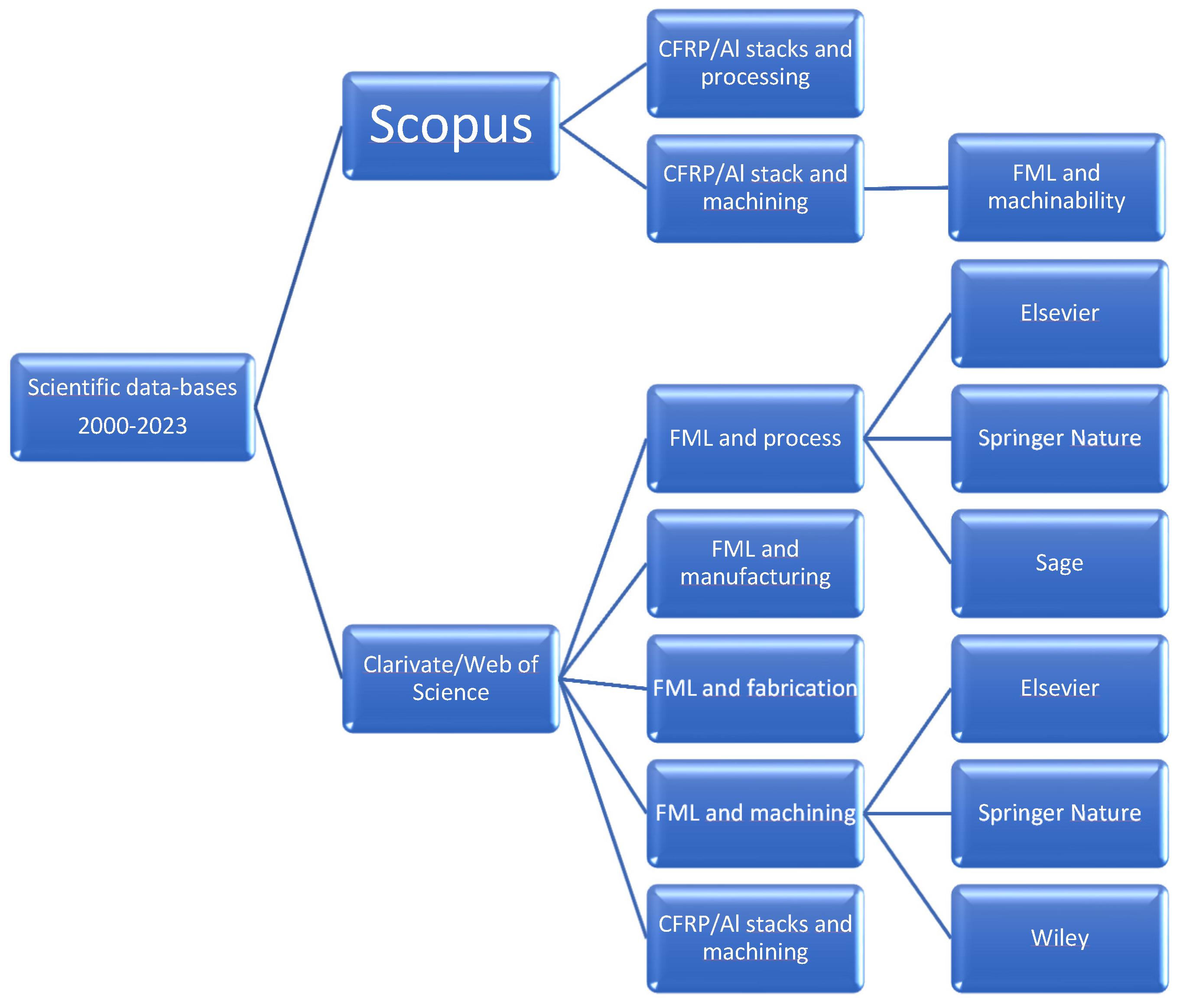
Using the Web of Science search tools, the publication selection started with the combination of the keywords FML and process (6504 papers found), FML and manufacturing (3014 papers found), FML and fabrication (2439 papers found) and FML and machining (856 papers found). The number of papers decreases when a specific keyword is used. If the keyword FML is changed to “CFRP/Al stacks and machining”, the number of papers decreases drastically to 37. Using the Scopus search tools, the combination of the keywords CFRP/Al stacks and processing or CFRP/Al stacks and machining yielded 4445 papers and 3104 papers, respectively, indicating that this research platform has more specific papers related to the topic discussed here. As mentioned above, the number of papers decreases when a specific keyword is used. In this case, when the keyword “CFRP/Al stacks” is changed to “FML and machinability”, the number of papers decreases drastically to 24. The diagram presents the route followed to reach the best literature information about the FML machining process (Figure 4).
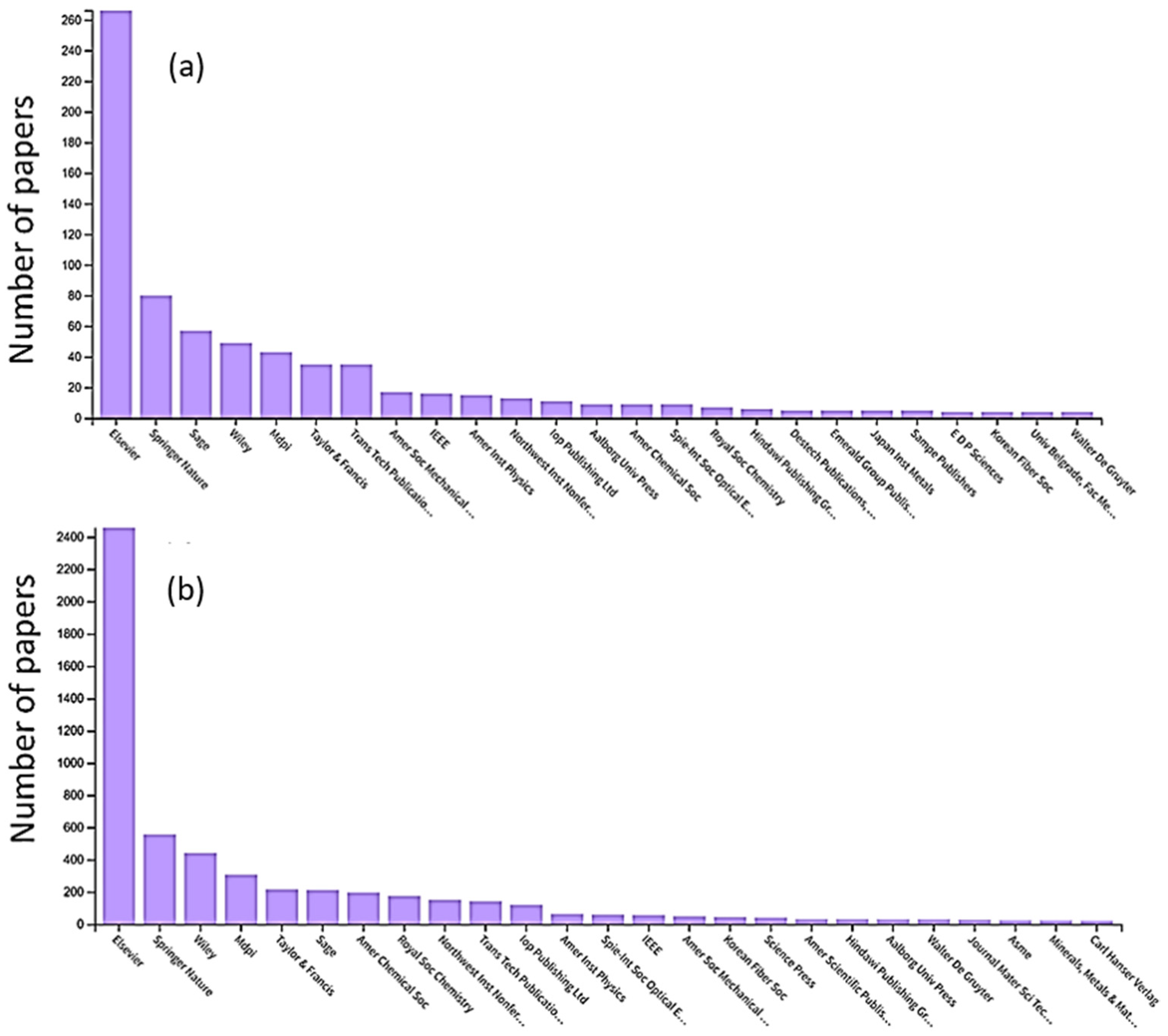
Using the keyword “FML and machining”, the first three publishers with more publications on the subject are Elsevier, Springer Nature and Sage, and using the keyword “FML and process”, the first three publishers with more publications on the subject are Elsevier, Springer Nature, and Wiley, as can be seen in Figure 5a,b.
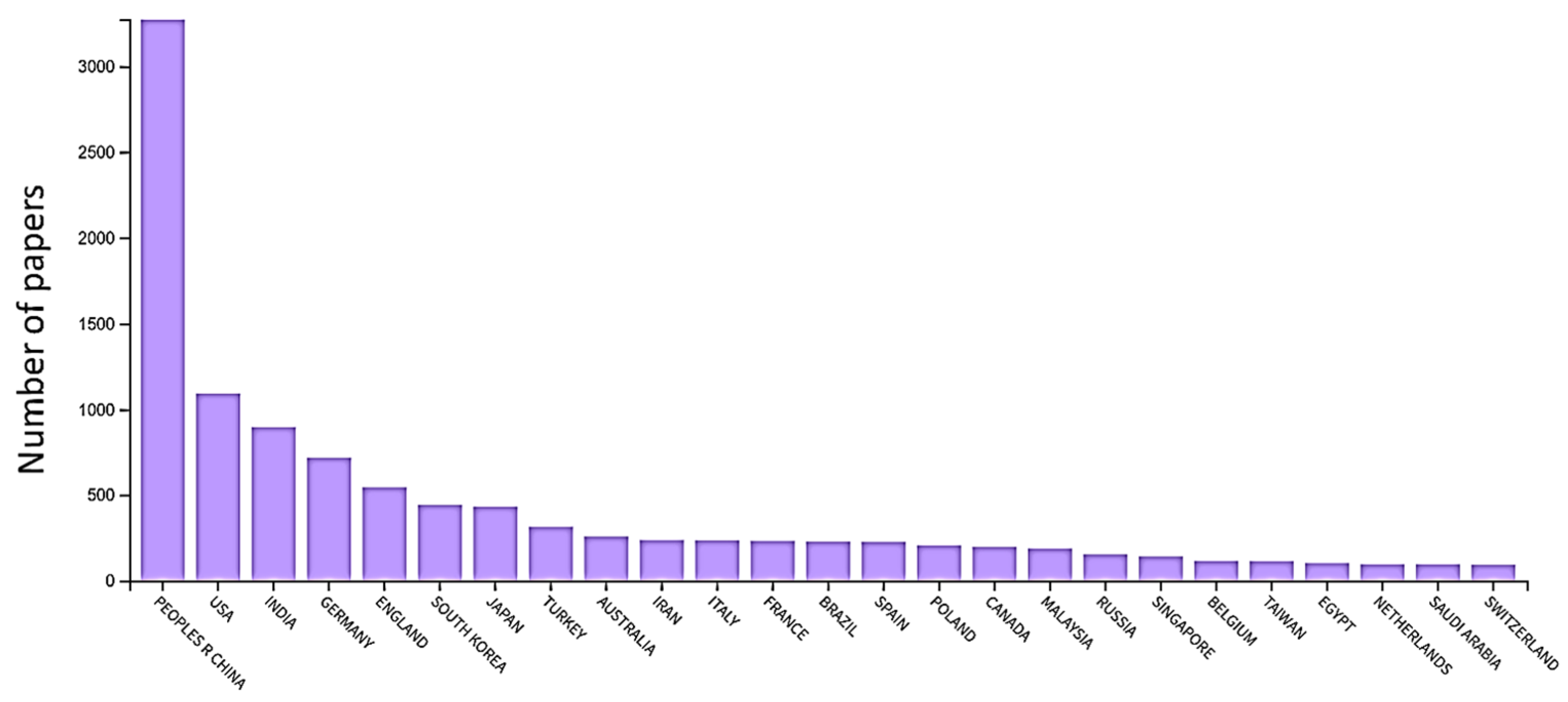
Another relevant piece of information extracted from the database was related to the countries that most published on the subject of FML machining, and it can be seen in Figure 6 that China leads the publications, followed by the USA and India, with Brazil being in the 13th position.
The literature review is divided into three main sections: (i) multi-material, (ii) machining tools and (iii) process sustainability. The first section discusses the multi-material manufacturing process, focusing on CRFP/Al stacks and CRFP/Ti stacks, followed by the main machining processes: drilling and milling, addressing the most used coatings and substrates for use in multi-material drilling/milling processes. The same section will also cover process parameters and the main lubrication methods used in multi-material machining. Finally, the main process failures according to quality levels and acceptance criteria will be presented, as well as how to analyze these process failures. The second section examines the types of tools used in the machining processes in terms of geometry, the presence or absence of coatings, and the tool wear. Finally, in the third section, the importance of studying the sustainability of the process is presented regarding the recycling or reuse of the chips produced for the different thermoplastic and thermosetting composite materials, and regarding the products used for cooling during the machining process, considering the gains in operational efficiency.
2.2. SWOT Analysis
The SWOT analysis reinforces the vision of the strategic context, helping in the knowledge of characteristics on the theme that may not be apparent, in addition to also helping to understand its importance in the market. It is one of the tools that allows a broad view of the theme under study, considering the internal analysis of the process (Strengths and Weaknesses), which can be controlled, and the external analysis (Opportunities and Threats) are elements that cannot be controlled, but their understanding is essential to create the strategic plan of the process [48,49]. The SWOT analysis is carried out to identify where the multi-material machining process turns the threats into opportunities.
The information to carry out the SWOT analysis was extracted from the bibliographic review of the multi-material machining process and corresponding critical analysis. From the information collected, a list of strengths and weaknesses, opportunities, and threats was created by comparing the different sources of information. After compiling the lists, the most relevant items were prioritized, for an effective analysis of about 3 to 5 items per category that were highlighted as relevant. The items were crossed to check the relationships between them and were rated from 0 to 3, where 0 is no relationship, 1 is a weak relationship, 2 is a moderate relationship and 3 is a strong relationship. Based on the SWOT matrix, improvement actions will be established for the topic, identifying opportunities, weaknesses, sustainability and threats to the multi-material machining process.
3. Multi-Material Machining Processes
3.1. Multi-Material Process Preparation
The manufacturing process for FMLs is similar to that for polymer composites, using an autoclave process. To produce an FML, six steps must be followed: (i) sheet metal surface preparation, (ii) material deposition: prepreg and metal layers, (iii) mold cleaning and vacuum bag preparation, (iv) curing process, (v) stretching process, and (vi) inspection, usually imaging techniques, and mechanical testing [1].
All these steps must be carefully followed to obtain an FML with excellent mechanical quality, which depends on the correct choice and execution of the material preparation methods. A weak interfacial interaction between the prepreg and the metal can lead to a delamination process in composite structures, which is a major defect. The correct choice of surface treatment is then required to improve the bonding energy between the materials [47].
Adhesive bonding processes such as chemical, coupling agent, dry, electrochemical and mechanical surface treatments can be used as single or combined methods to produce an FML. All these surface treatments change the surface topography and increase the surface roughness, as well as the interaction between the metal and the bonding site.
Some surface treatments were used as a single method. Kwon et al. [21] used a single method, sanding, a mechanical surface treatment, using three types of sandpaper and different sanding times. They concluded that longer sanding times increased surface energy and improved mechanical adhesion between metal and composite. Drozdziel-Jurkiewicz et al. [22] investigated some aluminum and titanium surface treatments using mechanical, chemical and electrochemical methods to achieve high adhesion at the metal-composite interface. These surface treatments improve the interfacial fracture toughness of the FML, increase the bond strength and provide high adhesion at the FML interface. The study showed that chromic acid anodization is still the most effective in improving the expected bond strength. In their studies, Thirukumaran et al. [20] used the first step, mechanical abrasion, to create a roughened surface at the macro level and remove an unwanted oxide layer. They then tested the chemical process, also known as acid etching, using two chemical solutions: potassium dichromate and ferric sulfate. The treatment with ferrous sulfate, which contains SO42e ions, had a better performance, promoting pitting, which increased the roughness and favored good adhesion between the substrate surfaces, as indicated by the higher tensile strength values.
Laser and plasma techniques are also used for the surface treatment of aluminum sheets to produce FML. Dieckhof et al. [50] treated AA2024 and AA5028 sheets and found that both techniques allowed the formation of a structured anodic oxide layer, which improved corrosion protection and interfacial adhesion. Park et al. [51] prepared the metal surface by mechanical abrasion, followed by phosphoric acid anodization and alkaline acid etching techniques. They also observed that the rough substrates were essential to improve the bond strength of the metal sheet-prepreg interface. In addition, they understood that selecting different autoclave pressures can influence the quality of the FML, reducing the void content and avoiding premature failure of the FML. Furthermore, Cheng et al. [52] optimized the production of pores on an aluminum substrate. They chemically treated the metal surfaces with three different electrolytes, all containing SO42e ions combined with oxalic acid and/or ferrous sulfate. To improve the interfacial adhesion between the composite and the metal sheet, they also used CNTs for interfacial bridging and final bond strength. They concluded that a rougher substrate surface potentially helps to improve wetting, contact area, and mechanical occlusion of the bonded joint.
Analyzing the surface treatment process in aluminum alloy found in the literature, the combination of mechanical and electrochemical methods is the best used to reach excellent surface preparation. All the papers analyzed showed that a good surface preparation favors an adequate roughness of the sheet metal surface, contributing to an optimal mechanical interlock and excellent interfacial adhesion, thus guaranteeing an FML of sufficient quality so that it can be machined without suffering delamination processes.
3.2. Numerical Simulation Applied to FML Machining
The numerical simulation technique is an economical option used during the development of a product or process. In the numerical simulation, the cost of equipment and man-hours is lower compared to the equipment used in lubrication processes, finishing, and the qualification of the finished product, as it includes the cost of acquisition, maintenance, and man-hours per machine. In this way, numerical simulation helps to reduce costs if it is carried out before experimental tests, reducing the number of tests, and making the choice of parameters more reliable. In addition, numerical simulation can be used to help understand the mechanism of the machining process by predicting cutting forces and temperature effects.
In the aeronautical field, the FML machining process requires a proper design of the processing parameters to avoid the occurrence of various problems and to minimize defects dependent on the process temperature variation, which can be detrimental to the integrity of the parts. These aspects become more critical in dry machining, such as matrix burning, fiber extraction and delamination.
In their work, Parodo et al. [53] monitor the temperature measured on the tool and the workpiece during dry drilling of Al/GFRP (GLARE) and Al/CFRP (CARALL). The influence of cutting speed on the temperature trends was analyzed. In addition, a numerical model was developed to analyze the process of temperature evolution during drilling. The numerical simulation also indicated that the temperature fields are dictated by the thermal properties of the carbon and glass fibers: temperature profiles within the CARALL were found to be smoother than those observed in GLARE. Giasin et al. [40] studied the machinability of GLARE laminate by experimental techniques and analytical simulation. The chosen parameters were the effect of feed rate and spindle speed on the cutting forces and hole quality. A 3D FE model was also developed to help understand the mechanism of drilling GLARE. To evaluate the numerical model’s efficiency, the collected thrust force and torque data were compared, and it was shown that the FE drilling model can predict the cutting forces within acceptable levels. It was the first contribution to the simulation of the drilling process of FMLs. Zitoune et al. [54] investigated the effect of machining parameters and tool geometry on cutting forces, hole quality, and CFRP/Al interface using experimental and numerical simulation. From the experimental study, it was found that the tool-enhanced geometry induced less thrust force compared to the standard one. The numerical analysis was based on the linear fracture mechanics of the CFRP and the plastic behavior of the aluminum with isotropic hardening. The results showed the critical thrust force responsible for the delamination of the last layer as a function of the aluminum thickness and, on the other hand, the maximum shear force responsible for the separation of the CFRP/Al interface was predicted as a function of the aluminum thickness.
Kim et al. [41] presented a method for predicting a cutting force model to optimize the feed direction. In this study, they used a CFRP with six different absolute fiber orientation angles. The fiber cutting angle significantly affects the cutting characteristics of the material and can be easily changed by varying the feed direction. By changing the feed direction angle, which is a simple adjustment in the milling process, this method effectively reduces the cutting force in material milling. In addition, since a predictive cutting force model is used, it is possible to derive the optimum feed direction under different cutting conditions with minimal experimentation.
Numerical simulation of the drilling process is relatively new; therefore, it is an area in the machining process that can be explored. It was observed that many of the authors investigate the influence of tool geometry on cutting forces and the delamination process of the material. However, a smaller number of authors study the temperature change in the profiles and how this can affect the properties of the material, the tool or can even be useful to study new types of lubricants that are more sustainable.
3.3. Multi-Material Machining Processes
Conventional machining processes such as drilling, milling, turning, and water jet cutting can be applied to composites, as long as the correct tool design and operating conditions are used. An FML is difficult to machine due to its anisotropic properties, inhomogeneous structure, and high abrasiveness of its constituents. These operations typically result in damage to the laminate such as fiber debonding, spalling, matrix cracking, fiber failure or pullout, and very fast wear of the cutting tool [55,56].
In the aerospace industry, the FML is used because of its light weight and stability at elevated temperatures. In these composite structures, large numbers of cut-outs and holes need to be produced. As mentioned above, FMLs are basically composed of a sheet of metal, aluminum, or titanium, and composite, carbon or glass fiber reinforcement, and a thermoset or thermoplastic matrix. Composites require high speed and low feed, drilling titanium requires low speed and high feed, while drilling aluminum requires a balance between speed and feed. Accordingly, the great challenge to drilling the FML is the right choice of parameters processes because of the materials’ constituent properties that also vary with the environmental conditions [57].
Kumar et al. [58] compared the machinability of conventional drilling of hybrid titanium/carbon-fiber-reinforced polymer/titanium (Ti/CFRP/Ti) stack laminates in a single shot under dry and cryogenic conditions. The results indicate that the low temperature affects the hole quality but increases the thrust force due to the increase in the hardness of the Ti sheet at low temperatures. Azwan et al. [59] investigated the effect of different drilling parameters on FMLs, such as the drilling speed, feed rate and thickness of the FMLs on the strength of composite materials. They concluded that drilling at a lower spindle speed and a lower feed rate generates higher workload than at a higher speed, for the same feed rate. The thicker FML induces an higher workload compared to the one with less thickness. Zitoune et al. [60] studied the influence of cutting variables on thrust, torque, hole quality and chip during the drilling of a CFRP/Al stack. They observed that the magnitude of thrust force and torque during the drilling of Al compared to CFRP is doubled at a low feed rate. Hole circularity and surface roughness increase with increasing feed rate. The aluminum layer also has a better finish compared to the CFRP one.
Another machining process to produce holes commonly used in aircraft part finishing is milling. The milling process uses rotary cutters to remove material by advancing a cutter into a part. This method is used as an alternative to drilling these joints with conventional twist drills, named after helical milling, where a milling tool rotates in a helical path and creates the hole [61]. Helical milling has also been investigated for making holes in FMLs, with several advantages such as lower cutting forces, lower heat generation and easy chip evacuation [62]. The main difference between drilling and helical milling is that in the former, the hole diameter is determined by the tool diameter, whereas in the latter, the hole is defined by a combination of the tool diameter and the helical path, resulting in greater flexibility in the hole diameter [63].
One of the compounds used in the aerospace industry that is difficult to machine is a unidirectional CFRP and Ti6Al4V, due to the hardness characteristics of titanium sheets and the abrasive characteristics of CFRP. They observed diameter variations, which may be due to the different Young’s moduli of titanium and CFRP, as well as variations in surface roughness caused by material-specific chip formation mechanisms [61]. Hemant et al. [64] evaluated the helical hole milling process in GLARE laminates. Although the material and parameters are different from those used by [61], similar process dissimilarities were observed, with variations in hole diameter depending on the material layer, production of discontinuous powdery chips and surface roughness. Therefore, to obtain an excellent quality finished product, the milling process parameters need to be adjusted to produce holes of uniform diameter throughout their depth, continuous chips in the metal zone, low surface roughness and a composite layer without delamination.
3.3.1. Comparison of Drilling and Milling Processes Parameters
The different properties of the constituent materials in FMLs are a challenging task when hole-making is needed. Improper selection of the process and process parameters can result in poor surface quality, inadequate dimensional quality, dimensional inaccuracy, or even component failure [65].
However, there are several interrelated factors. The most crucial factors which affect the machinability of the material are cutting forces, tool geometry, materials, coatings, chip formation, analysis of tool wear, hole metrics such as the hole size and circularity error, surface roughness and burrs formation [66]. Bolar et al. [65] compared two hole-making techniques used in CARALL: drilling and milling. In their study, the two hole-making techniques were evaluated using various performance measures including thrust, radial force, chip morphology, surface roughness, machining temperature, hole diameter accuracy and burr size. Comparing the results, the authors found some advantages of the helical hole milling process in terms of lower thrust and radial force. The intermittent cutting and convenient chip evacuation and heat dissipation helped to lower the temperature and prevent some material damage. The discontinuous aluminum chips produced by the helical milling process proved to be beneficial, with the holes showing a superior surface finish. However, excessive axial feed in helical milling resulted in tool deformation and chatter, leading to surface quality degradation. Further analysis of the machined surface using microscopic inspection showed that the delamination process occurred when conventional drilling was used. On the other hand, the helically milled hole was free of such defects and showed no signs of delamination. They also found that the formation of oversized holes after the drilling process was incredibly significant. Finally, the exit burr’s height was much lower with helical milling due to the lower thermal impact and lower thrust. Considering all the aspects presented here, it is safe to say that helical milling is a suitable alternative for machining holes in FMLs.
Another study comparing drilling and milling was carried out by Barman et al. [63]. In their work, they evaluated the two-hole machining process in titanium alloy Ti6Al4V material. They carried out the machining tests considering the thrust force, surface roughness, hole diameter and machining temperature. The morphology of the chips produced and burr formation were also investigated. The magnitude of the force components (thrust and radial force) and the cutting temperature was lower in the milling process, which produced discontinuous powdery chips that evacuated easily without damaging the machined hole surface. The final quality of the holes and the diameter are better in the helical milling process, which produced burr-free holes, contrary to drilling. A similar study using helical milling and drilling techniques to machine AISI D2 tool steel was previously carried out by Iyer et al. [67]. They found that helical milling produced H7-quality holes with good surface roughness compared to drilling. Another comparative study on helical milling of a larger thickness CFRP/Ti stack and its individual layers was conducted by Wang et al. [5]. Their experimental results showed that as the number of holes increased, the cutting forces increased due to tool wear and its dependence on the material type. Indeed, the abrasive nature of the CFRP resulted in an increase in cutting force. The hole edge quality is good while machining the titanium alloy, and low delamination is registered at the tool entry and exit points in the material, indicating that if quality problems of the holes appear, it refers to the milling of CFRP. Hole size was inversely proportional when comparing a single layer to a stack. In the drilling process, with CFRP, smaller hole sizes can be achieved compared to the titanium plate; however, oversized CFRP holes and undersized titanium alloy holes are observed when helically milling stacks.
Therefore, there is the agreement in the literature when comparing the drilling and milling processes. All results showed similarity regardless of the material used, Ti/CRFP stacks, Al/CRFP stacks, Ti metal alloy, CRFP or steel, indicating that the best process and the one that promotes less material damage is the helical milling process.
3.3.2. Lubrication Processes during Machining
During the machining process, a large amount of cutting heat and friction heat can be generated due to the abrasive nature of the material and tool wear, which usually makes the temperature elevate rapidly. Temperature is one of the most important factors affecting the machined hole surface quality, especially for the CFRPs. When drilling CFRPs, the temperature can reach about 150~250 °C, leading to a risk of thermal degradation of matrix resin, carbonization of thermosetting matrices, the fusion of thermoplastic matrices, and sometimes, burning of the carbon fibers [68]. In addition, the thermal effects can affect the quality of machined holes. These, however, can be minimized using coolants supplied either directly or indirectly to the cutting tool-workpiece interaction zone, to remove part of the generated heat. Nevertheless, the use of coolants adds extra costs for handling, disposal, and environmental impact [69].
The coolants generally used in machining processes are water-oil emulsion, a mixture of a soluble oil cutting fluid and mineral oil lubricant [70], micro-lubrication, also known as minimum quantity lubrication (MQL) [71], cryogenic coolants CO2 [72] and liquid nitrogen (LN2) [73,74], air cooling [62] and vegetable oil [75], among others.
Shyha et al. [70] analyzed the hole quality/integrity after drilling of titanium/CFRP/aluminum stacks under flood cutting fluid water/oil emulsion of 7–8% volume solution and spray mist, a mixture of soluble oil cutting fluid and mineral oil lubricant. Some significant improvements in the machining process were observed. Burr height was generally less than 500 μm, except when spray mist was used. Delamination of the CFRP laminates was significantly reduced due to the support provided by the Al and Ti layers. Surface roughness was significantly lower when using through-spindle cutting fluid compared to spray mist application, especially on the Al section. Spiral-shaped continuous aluminum chips were prevalent, while both short and long helical chips were found with the titanium material when cutting under wet regime. In contrast, the CFRP layer typically produced dusty black composite particles suspended in the soluble oil of the coolant emulsion.
Kumar and Gururaja [76] investigated the cryogenic cooling effects during the drilling of Ti/CFRP/Ti stacks. The parameters such as thrust, torque, delamination, burr height and surface roughness were considered to investigate the effects of liquid nitrogen (LN2) as a coolant. The results are compared with those obtained from dry drilling of Ti/CFRP/Ti stacks, indicating that torque, top surface of metal composite interface, exit burr height and surface roughness decreased when drilling was performed under a cryogenic environment. Nonetheless, thrust force and damage to the lower surface of the metal composite interface are increased under LN2 cooling conditions. Biermann and Hartmann [72] analyzed a cryogenic process cooling with CO2 and found that the chosen coolant improved burr formation in drilling compared to dry machining and resulted in higher sustainability comparing to machining with cooling lubricant. Many authors have investigated the influence of the application of cryogenic liquid nitrogen cooling and minimum quantity lubrication (MQL) during GLARE machining. Giasin et al. [77] observed that the use of MQL and cryogenic liquid nitrogen cooling increased the cutting forces; however, both reduced the surface roughness of machined holes, adhesion and built-up edge formation on the cutting tool compared to dry drilling. Examination of the microhardness of the top and bottom aluminum sheets near the hole edges after machining showed that it increased when both coolants were used. Pereira et al. [62] reported some benefits of air-cooling application. It was used to cool the cutting point and to remove the chips, obtaining better results in terms of cutting forces and temperature. The cutting temperature reduction in helical milling was 30%. When drilling the CFRP, the cutting heat becomes lower by increasing the revolution speed. Chips pulverized into small sizes reduce cutting temperature by absorbing heat on the cutting of CFRP composite plate. However, the powder-like chip is bad for the machining center, even promoting corrosion and wear of part of the equipment.
Lubricants and coolants play an important role in the machining process to prevent delamination damage in the material during the drilling process, especially in FMLs, because the difference in modulus of elasticity between composite and metal causes different machining deformations. The main defects observed after machining and their discussion are presented below.
3.3.3. Machined FML Defects and Analysis Techniques
Drilling holes in both CRFP and FML can result in material damage as the drill passes through the material. Several types of defects are associated with drilling operations, both at the entry and exit of the hole: dimensional defects, surface roughness and surface integrity problems of the hole wall. Defects induced by machining process conditions include matrix cracking, fiber fracture, debonding, delamination and fiber pull-out. Poor hole quality is the cause of nearly 60% of all scrapped parts [78]. As drilling is often one of the last machining operations, the damage that occurs at this stage results in huge economic losses when near-finished parts have to be scrapped. Understanding and detecting the type, size and location of defects that can occur during drilling operations is important for economical and sustainable process improvement [79]. This damage always occurs combined in hole-surrounding areas.
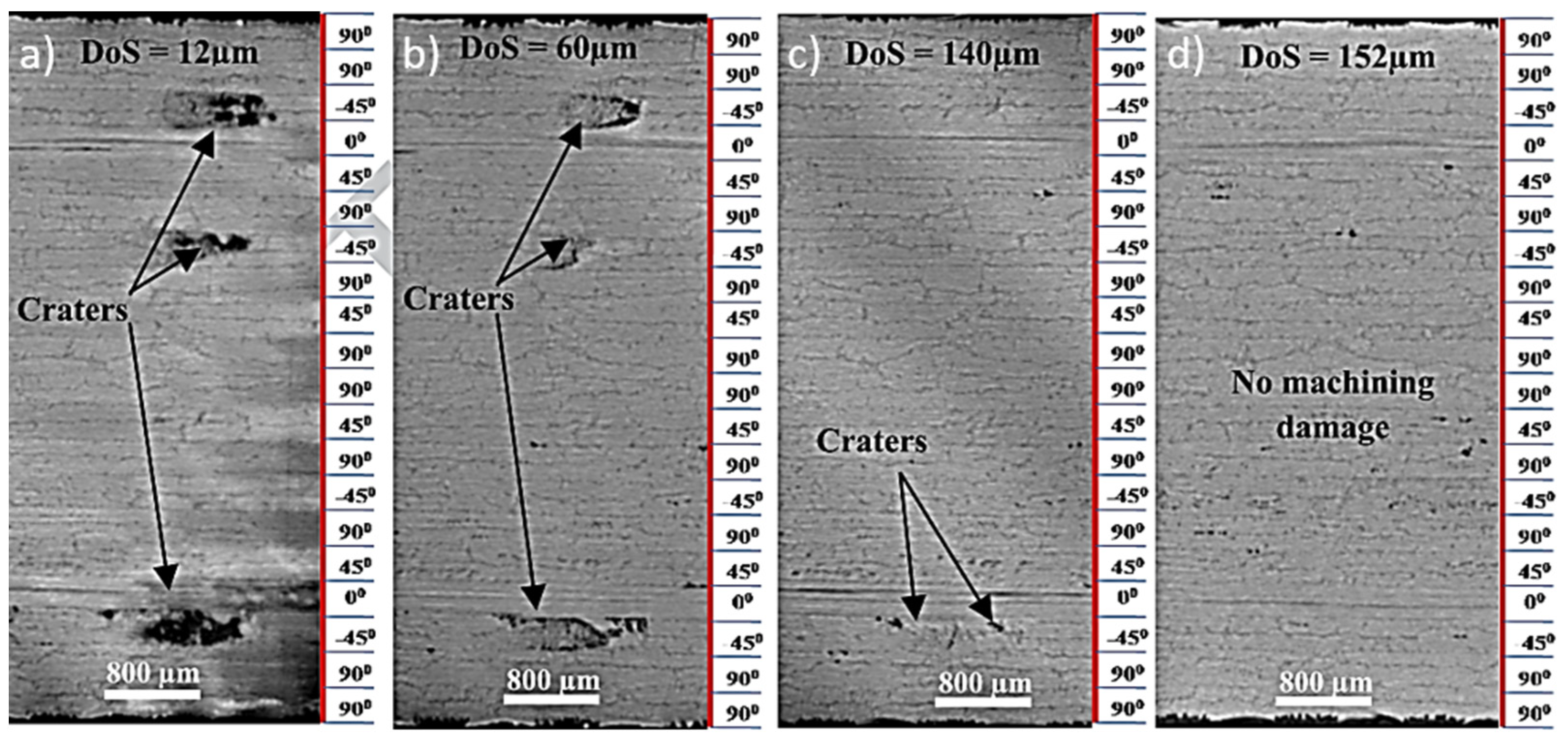
The great issue in FML drilling operations is the quality of the hole: several defects occur related to the process, mainly on the entry and exit sides of the hole, as well as dimensional and surface roughness issues of the hole wall. The detection of these defects is not trivial, especially when non-destructive methods are used. Several methods have been applied to evaluate the hole quality, such as Computed Tomography (CT)/X-ray Tomography Analysis [79,80,81]; C-Scan [82], Scanning Electron Microscopy (SEM), Stereoscopic Optical Microscopy (SOM), and Energy Dispersive Spectroscopy (EDS) [83]. Nguyen-Dinh et al. [84] analyzed the surface integrity of composites using x-ray tomography after trimming process. The application of the X-ray technique has enabled the measurement of the craters’ volume compared with surface techniques, such as surface roughness and 3D optical topography. They observed several damaged zones with formation of craters in the material surface after trimming process, indicating material pull-out (Figure 7).
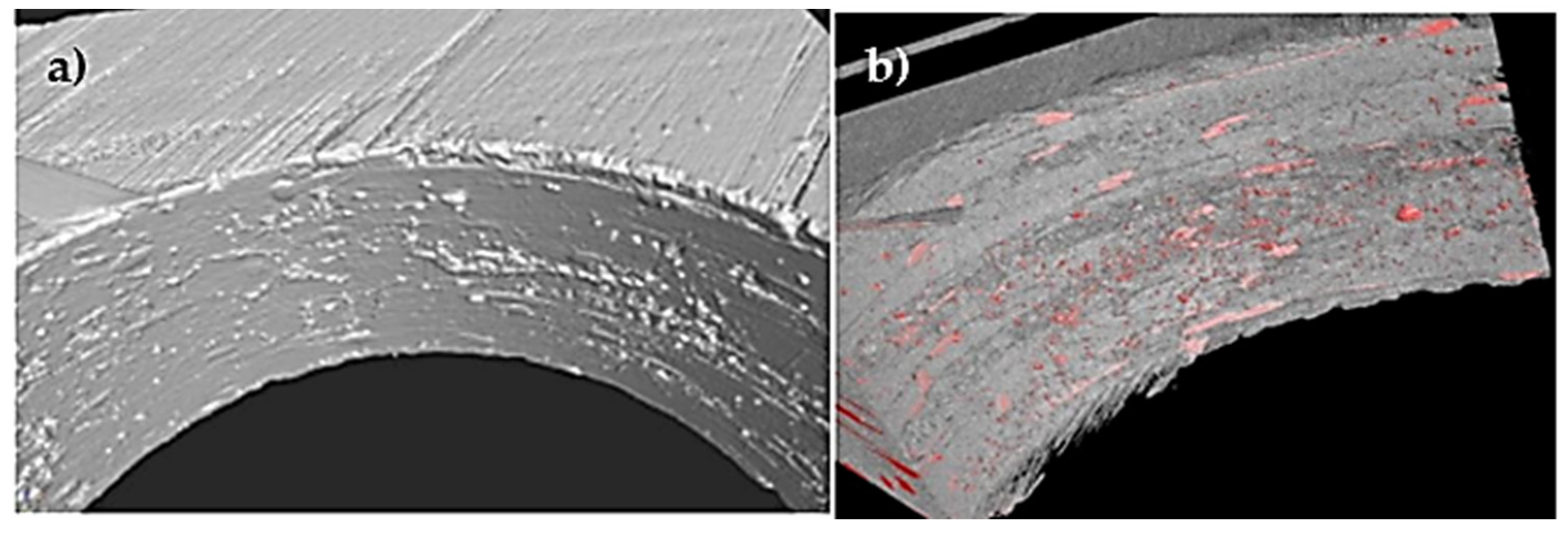
Pejryd et al. [79] used X-ray computed tomography to detect defects caused by drilling holes in a CFRP. Surface defects and surface properties such as fiber debonding and surface roughness could be easily investigated. Figure 8a shows a typical surface image of a drilled hole based on the reconstruction of the X-ray images. Figure 8b illustrates one way of highlighting the glass fiber material. This technique allows other components to be identified by color. In this case, a red color is used to clearly distinguish it from the surrounding material.
Wang et al. [85] compared the holes’ quality of CFRP/Al and CFRP/Ti-6Al-4V by Scanning Electron Microscopy (SEM). To reduce the damage, a two-step process of helical milling process was proposed and compared with that of conventional drilling. In the first step, milling was executed starting on the composite part, and then, in the second step, milling started on the metal part. In the conventional drilling process, they noticed that the damage is superior when the tool entry starts on the composite part, showing many uncut fibers (Figure 9a). The cutting action of the second step eliminates the damage caused by the first step, but the surface next to the hole showed fiber pull-out (Figure 9b). The images showed that the damage induced by the helical milling process in both steps is irrelevant.
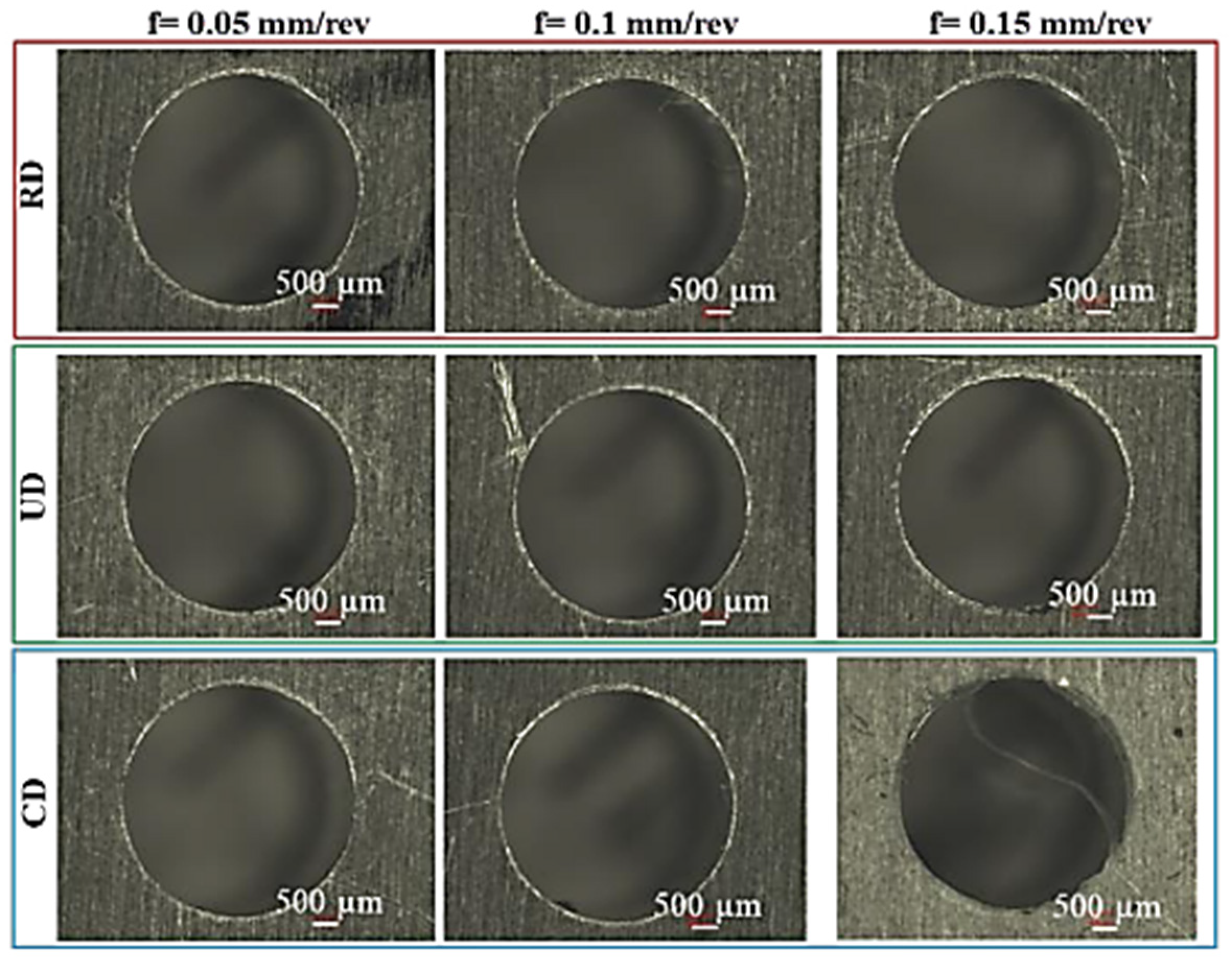
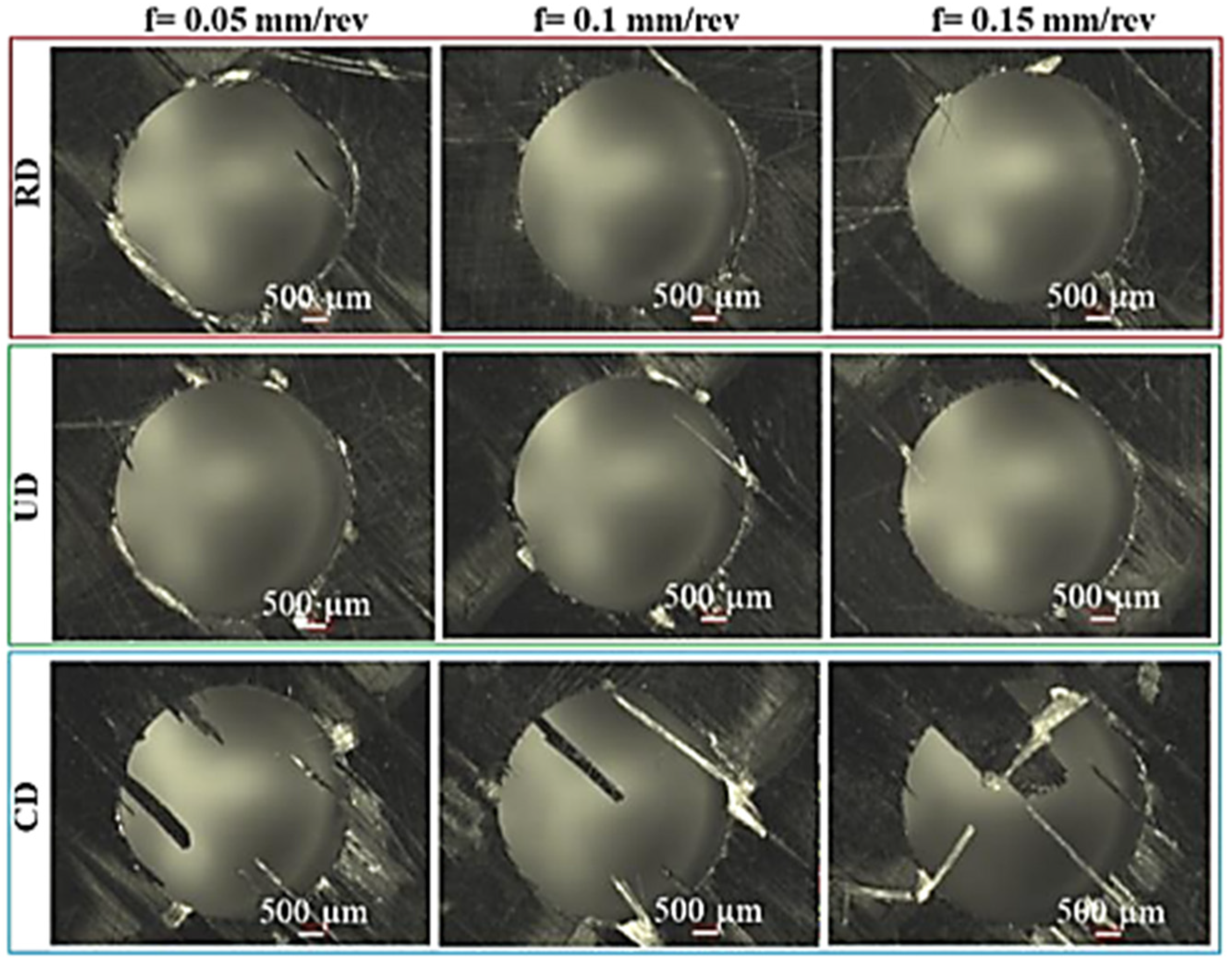
The minimization of delamination damage is of great importance, because it is a critical parameter that determines the acceptance or rejection of composite components. To achieve this proposal, Bertolini et al. [73] analyzed the hole quality of an Al/CFRP stack obtained by different drilling processes: ultrasonic (UD) and cryogenic (CD) and compared with dry drilling/regular drilling (RD) using the SEM technique. The feed rates used were 0.05 mm/rev, 0.1 mm/rev and 0.15 mm/rev. The FML was composed of two layers: one of 5 mm thick aluminum alloy considered the entry face, and the second one composed of a 4 mm thick CFRP sheet, considered the exit face. They were evaluated solely at the exit, since the entrance appears defects free (Figure 10).
Figure 11 shows the exit face where the delamination process occurred to a greater or lesser extent depending on the variable feeding and drilling strategy. Severe exit delamination occurred solely when drilling tests were conducted under CD, regardless of the adopted feed. This phenomenon can be correlated to the thrust force increase thanks to the hardening of the material as a consequence of the liquid nitrogen application. It is acknowledged that the higher the thrust force, the greater the exit delamination, because the deflection of the FML’s last ply concerns a larger zone.
These techniques already guarantee by themselves the analysis of the damage caused by the machining process, but when combined with other image analysis techniques cited here, they improve the accuracy of the analysis, complementing the information and being a determining factor for adjusting process parameters.
To reduce damage during the machining process, it is important to choose the correct tool and tool wear. Therefore, Section 4 deals with this subject in order to provide as much information as possible on the possible tools and tool wear used for multi-material machining.
4. Machining Tools
There are several different types of tools used in the machining operations on composites and multi-materials, depending on crucial factors, namely, the process and the material to be machined. According to these, a set of variables has to be chosen, such as the tool material, geometry or need for a coating, from which a large range can be employed. These factors will result in determined cutting forces and torques, which will impact the base material, considering its final roughness or the existence of delamination, and the tool, in particular its wear mode, in a specific way.
In order to optimize the machining process, the desirable mechanical properties for a cutting tool material are small grain size, to produce a sharp cutting edge, good toughness, to keep the sharp cutting edge without chipping or deformation under the dynamic action of the cutting forces, and high hot hardness, to provide a great resistance to abrasive wear under elevated cutting temperatures. In terms of thermal properties, since the temperature rises abruptly during the process, the tool needs to possess a good thermal conductivity to remove heat from the cutting zone, thermal stability, to maintain integrity at cutting temperatures and low chemical affinity to the workpiece material [57].
The preferable tools in the literature for drilling composite-metal stacks are carbide tools such as tungsten carbide, due to their high strength and wear resistance compared to HSS/HSS-Co tools. These also are among the ones most used, alongside Poly-Crystalline Diamond (PCD) tools [86].
4.1. Tool Geometry
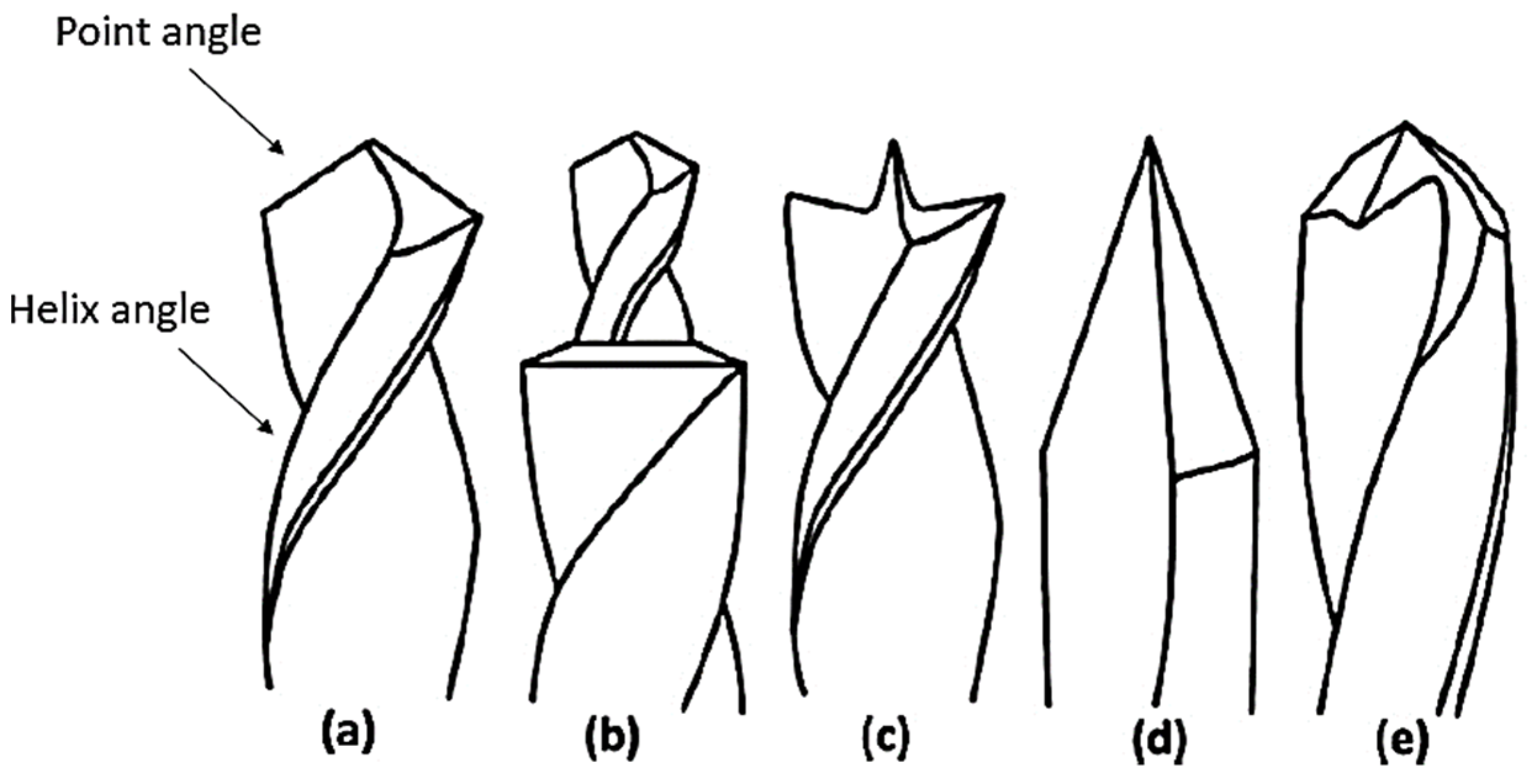
When referring to the geometry of the tools, each machining operation has a specific type of geometry, the most fit to perform a specific kind of work. In the drilling case, there are two important angles to be considered, namely, the point angle and the helix angle. The standard helix angle for most drills is 30°; however, in spite of most drills coming with a 118° drill point angle, when it comes to drilling composites, it is recommended to use a drill bit with a point angle between 130° and 140°, values also used in aluminum drilling. A cutting tool with large helix angle, usually higher than 24°, allows a quick chip evacuation, whereas large point angles improve chip removal and reduce burr formation. The increment of these two parameters, seen in Figure 12, also minimizes surface roughness [87]. Additionally, this figure presents the various drill geometries for specific drilling operations.
The step drill is one of the drilling strategies to avoid material damage around the hole, for example delamination, as it first inflicts a primary hole, with a smaller diameter, and then it drills the intended size, so as the contact with the substrate is smoother [88].
Apart from the already exposed geometries, tools with special designs have been proposed to decrease the probability of delamination and obtain better productivity. In this matter, double helix tools minimize axial forces by utilizing two opposite helix angles [89]. Double point and multi-facet drills were also developed, producing lower thrust forces, due to an additional cutting edge [90]. In the case of milling, the multi-tooth milling cutter could significantly minimize milling defects for CFRP and decrease cutting forces [91].
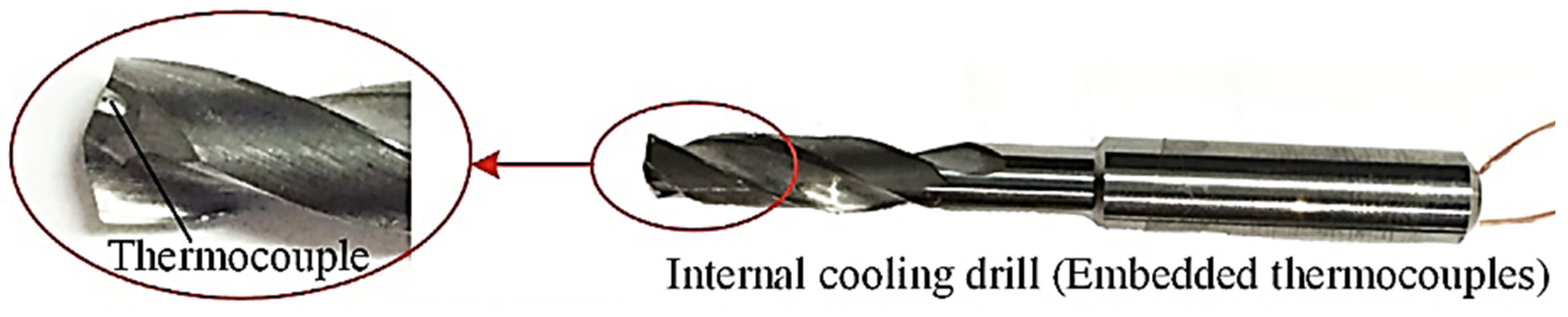
When there is a need to measure the temperature reached in drilling processes, a thermocouple can be inserted into the drill bit lubricant-cooling fluid holes, as shown in Figure 13. The thermocouples do not necessarily have to be positioned in the same place for every case, meaning that one device may be in the sharp edge and other in the flank of the drill. This is a more complex procedure, but this way a more complete analysis of the temperature reached by the tool can be achieved, with information from different areas, each of which is subjected to a specific stress and, therefore, temperature [92].
This set-up allows the measurement of the temperatures arising in the tool during the drilling. Thermocouples may also be inserted inside the multi-material: one in the composite laminate and other in the metal sheet. Although in the last years, alternative approaches to measure the temperature during the machining processes have been proposed, less invasive and relying on no-contact methods, such as infrared pyrometers or infrared cameras, the thermocouples are still the most effective method [53].
4.2. Tool Coatings
Two of the most prominent types of coating methods are the Physical Vapor Deposition (PVD) and Chemical Vapor Deposition (CVD). In the case of the latter, which uses higher temperatures on the process, the coating is synthesized from a mixture of different gases, depending on the type of coating being deposited [94]. On the other hand, the PVD technique intensively improves the wear resistance of different tools, effectively increasing their lifespan [95].
Studies show that the correct application of a coating is more effective than an uncoated tool in drilling multi-materials [96]; however, this is only true for higher feed rates and cutting lengths, severe conditions, as coated tools possess a much higher cost, so these are only applied when strictly necessary. Coated carbide tools such as PVD coated Boron-Aluminum-Nitride (BAM) tools have a better performance compared with uncoated tools in terms of tool wear at severe drilling conditions. In spite of this, prolonged tool life came with the price of rougher finished surfaces due to roughness of the BAM coating [86].
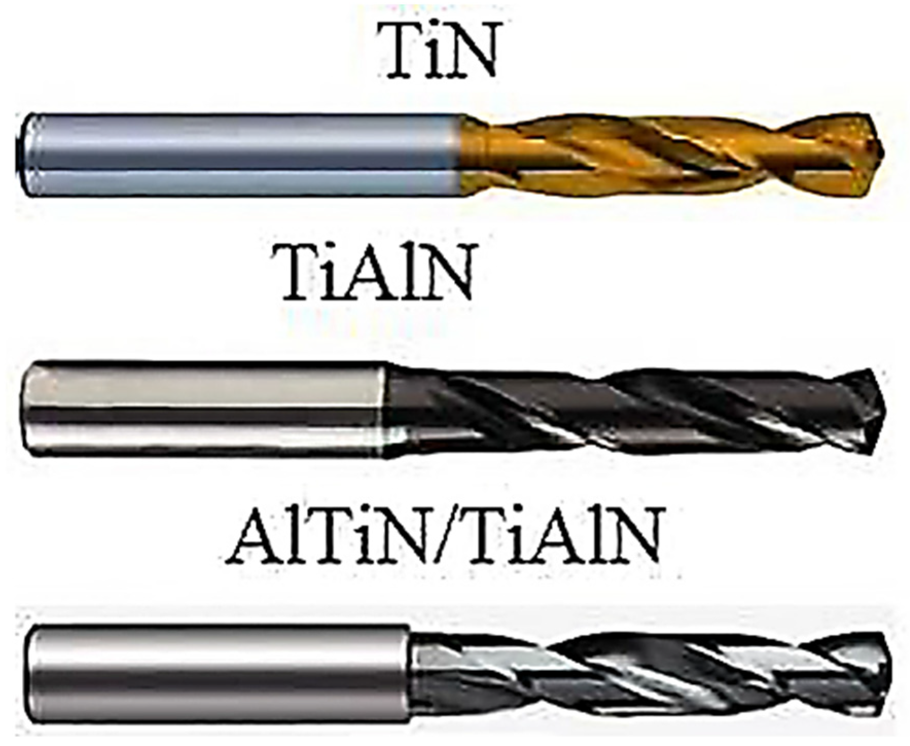
Figure 14 shows three different types of coatings which are common for rotary tooling such as drilling, being two monolayer (TiN and TiAlN) and one multilayer (AlTiN/TiAlN). The latter combines two layers for better heat and wear resistance [87]. From a study performed with these three coatings, the TiAlN drills produced the largest thrust and cutting forces, with the AlTiN/TiAlN resulting in the lowest values. Additionally, this coating presented a better self-lubricating effect due to its multilayer structure, which also increases its hardness, resulting in a better performance achieved during drilling [97].
Diamond CVD coatings are many times chosen as well, due to their enhanced characteristics when compared to the remaining options, although sometimes they experience some lack of adhesion. Nevertheless, when these problems are overcome, diamond coatings provide a longer lifetime when put side by side with other coating materials [98]. Its high thermal conductivity contributes to a temperature decrease in the cutting tool surface, and a low thermal expansion coefficient mismatch allows obtaining a good adhesion between the CVD diamond film and the ceramic substrate, as a result of a lower interface residual stress at room temperature. It also contributes to an enhanced surface hardness, which leads to a decrease in the tool wear [99]. Diamond-like carbon (DLC) coatings are also often used in the literature as an alternative to a diamond film [100].
4.3. Types of Tool Wear
The abrasive nature of multi-materials, with consequences for the substrate in the drilling process, such as fiber pull out, particle fracture, delamination and debonding at the fiber or particle and matrix interface, causes severe tool wear [55]. This is one of the reasons a tool coating is employed several times, so it can be possible to extend the tool life as much as possible, thus improving the process and reducing the associated costs [55].
It has been found that the tool wear increases the cutting force values [101]. This can be explained due to the loss of the tool’s capacity to perform the intended job, as the contact surface with the substrate is reduced and its roughness increased, which is translated into higher cutting forces and less cutting quality. The types of wear suffered by tools during machining processes include adhesive, abrasive, fatigue and corrosive wear [57].
The adhesive wear, represented in Figure 15, can be produced by two different ways: directly, with high-speed chip particles impacting the tool, creating a micro blasting effect that reduces the cutting angle and the rigidity of the tool, and indirectly, by the incorporation of fragments of the substrate material to the tool [57]. When these fragments are removed, they can drag out tool particles, which leads to its wear by the loss of tool material, but also by the abrasion process caused by the friction of those particles with the tool rake face when they are dragged by the chip [84,102]. This abrasion action acts mainly on the flanks and outer corners of the drill bit in an irregular pattern, rounding its cutting edges and possessing various forms, such as crater wear, chisel edge wear and chipping [103,104,105]. Fatigue wear is the result of an excessive number of cycles performed by the tool, and the corrosive ones occur by a chemical reaction, degrading the tool material and thus keeping it from performing a proper cut.
Sometimes, a phenomenon that can occur is the clogging of the drill flutes with chips coming from the substrate, which prevents the drill from working correctly and therefore threatens the final quality of the product [57]. In this case, as well as with certain stages of adhesive wear, cleaning the drill with sodium hydroxide is required, with the aim to eliminate these negative aggregations and accordingly return the drill to its normal shape [106]. For the milling process of multi-materials, tools with diamond inserts possess good results, due to their high hardness [101]. The same method is applied in the drilling of FRPs, with diamond-mounted points to reduce the wear at the cutting edges, due to their high abrasive wear resistance [107].
5. Process Sustainability
Progress towards sustainable development is increasing in all industrial sectors. Within the integrated life cycle management strategy, the manufacturing phase is one of the key performance phases due to resource consumption, emissions, and other negative impacts. To minimize environmental, ecological, and social damage, sustainable manufacturing design must take into account the three dimensions of sustainability: environmental, economic and social [108].
The machining process is an important part of the manufacturing process; therefore, it is expected to have a great impact by improving sustainability performance. Among the elements of machines, conventional coolant application has been considered as a critical limiting factor to achieving better sustainability performance [109].
The machining process of high-tech materials requires oil-based cooling/lubrication, which is one of the main non-sustainable elements, leading the R&D process in the search for alternative cooling and/or lubrication mechanisms [110]. To achieve better sustainability performance, alternative approaches to conventional flood cooling such as dry machining, minimum quantity lubrication (MQL) and cryogenic machining have been applied. Comparing MQL and dry machining, a similar result is observed; MQL does not remove the heat generated in the cutting zone sufficiently. Cryogenic machining not only reduces the disposal of large quantities of lubricating oil used in machining, but also increases tool life by 60% [109].
Some authors have studied these three cooling methods and compared their findings. Nagaraj et al. [111] compared MQL and cryogenic cooling methods to drill a CFRP composite. They concluded that cryogenic drilling gives better results than dry drilling in terms of drilled hole diameter and roundness, and sequentially they considered the MQL method as the next best alternative to dry drilling. Sharma et al. [112] presented a review to understand the influence of different types of coolants, mineral oils, vegetable oils, and nanofluid-based cutting fluids with the help of the MQL technique. They concluded that MQL reduced cutting temperature and produced metallic color chips, showed a reduction in dimensional deviation, improved tool life, produced better surface quality and showed an approximately 40% increase in material removal rate compared to aqueous flood coolant. To facilitate the analysis of the sustainability of the machining process, Hegab et al. [113] developed a detailed and general assessment model for machining processes. The four life cycle stages (pre-manufacturing, manufacturing, use and post-use) are included in the proposed algorithm. Energy consumption, machining costs, waste management, environmental impact, and personal health and safety are used to express the overall sustainability assessment index. They applied the model to three literature case studies and found that it was able to predict optimal parameters in close agreement with the experimentally measured results. Lv et al. [114] applied a model of the energy efficiency, carbon efficiency, and green degree in five types of machine tools selected for the typical machining processes (turning, milling, planning, grinding and drilling). After a careful analysis, they observed the increase in the back engagement will increase the material removal rate, thus, its impact degree is small, and increasing spindle speed and feed rate will reduce processing time, energy consumption, and emission, thus presenting a positive correlation, reaching an energy efficiency of 30%.
To achieve a sustainable machining process and estimate earnings, it is necessary to establish new models that reduce this complexity in the design and management stage, allowing the development of task manufacturing to promote sustainability in the processes involved while maintaining technical, economic and quality feasibility.
6. Critical Analysis and Discussion
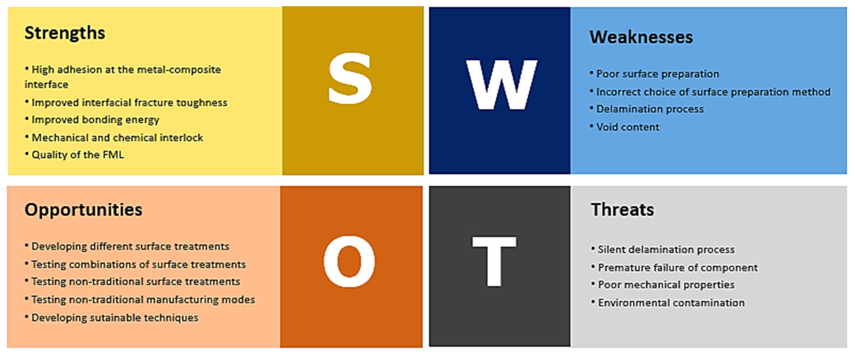
This manuscript brings an accessible joining of most relevant improvements made in the last two decades regarding the multi-material machining operations. Through several tables containing the state-of-the-art of different themes and respective SWOT analyses comparing the different research performed around the globe, this article serves as an aggregated encyclopedia, so that less time is needed to consult the necessary information on this theme. In order to show the opportunities for each of the main areas related to the machining process on FML and high-hardness materials, SWOT analyses have been developed. The first important issue explored in this paper relates to the FML manufacturing process. To obtain an FML with excellent mechanical properties, it is important to choose the right surface treatment in order to improve the adhesion between layers of dissimilar materials. To present the SWOT analysis, four papers were compared: Roth et al. [8], Drozdziel-Jurkiewicz and Bienia [22], Dieckhoff et al. [50] and Park et al. [51]. These authors were chosen due to the new approach of surface treatments on metal sheets to produce FMLs. The SWOT analysis of the surface treatment applied to FML stacks production is presented in Figure 16.
The most common surface treatments are mechanical abrasion and chemical treatment or a combination of them. Generally, these treatments create a rougher surface promoting mechanical interlock, chemical interlock, or both. Thus, it is important to have a deep analysis about what parameters can influence the interfacial adhesion. Combination of surface treatments improves the bonding energy between the dissimilar materials. A mechanical surface treatment, followed by a chemical one, creates deeper valleys that improve mechanical interlock between the polymeric matrix and metal. Some chemical binders are also used to improve the chemical bonding between metal and composite. New surface treatment techniques, such as laser and plasma techniques with a sustainable bias, should be tested to replace conventional, less sustainable techniques, in order to protect the environment and reduce costs.
In a conventional manufacturing process using an autoclave, the void content can be reduced, and the mechanical properties can be improved, but the production costs are high using this manufacturing process. The thermoforming process can produce a high-quality workpiece with lower cost when compared with the autoclave process.
The second SWOT analysis is related to drilling and milling processes in high hardness materials (Figure 17). The results of two papers found in the literature, Barman et al. [63] and Bolar et al. [65], were discussed to elaborate the SWOT analysis of drilling and milling processes. The authors chose to compare the efficiency of these machining processes in the titanium alloy Ti6Al4V and in CARALL. These papers were chosen because they address and compare the drilling and milling techniques of these materials.
The helical milling process has superior response to high-hardness materials when compared to the drilling process in all parameters studied by the authors, such as machining forces, chip morphology, machining temperature, surface roughness, hole size and burr size. The drilling process is in danger of becoming obsolete compared to milling, so it is necessary to renew the drilling process, such as the development of new tools, new coatings, lubricants and coolants, as well as a more detailed study of the drilling process parameters.
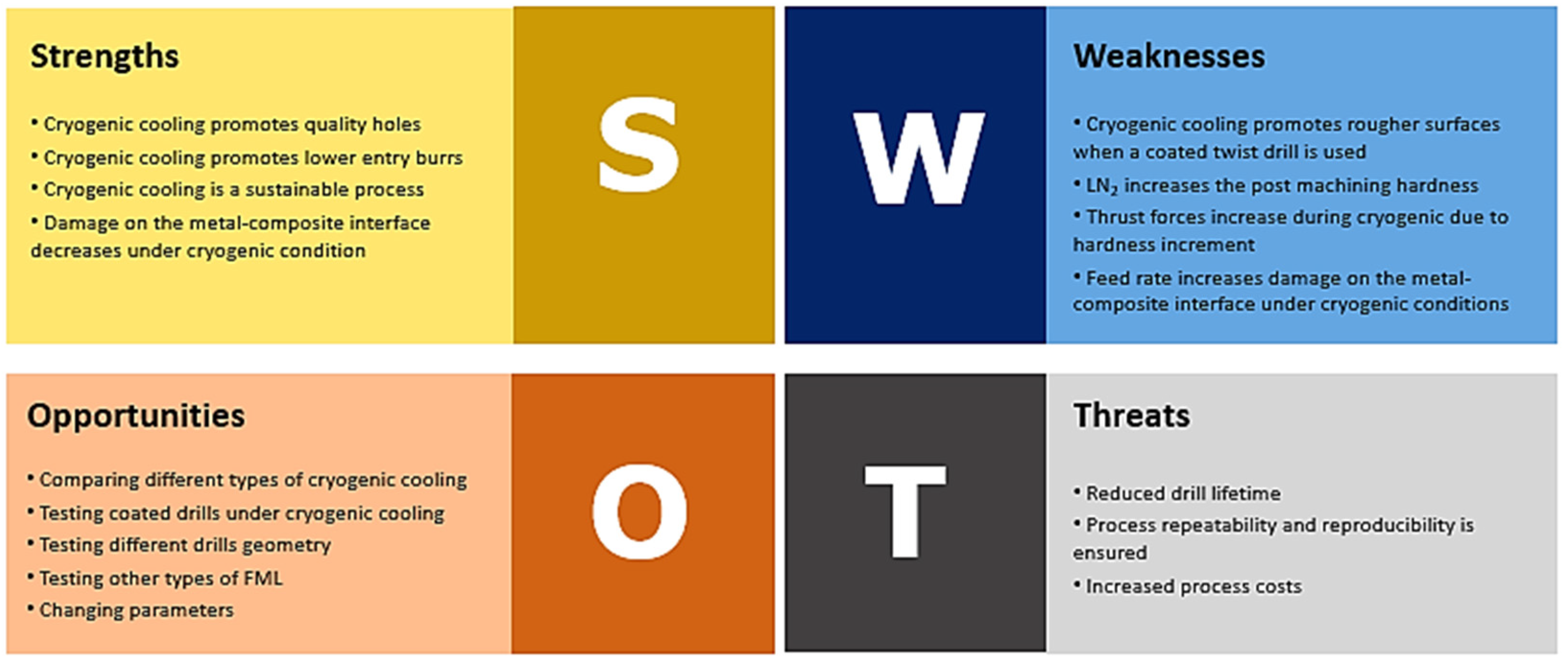
The last one is a SWOT analysis on the use of lubricants/coolants in FML machining. The results of three papers found in the literature, Bertolini et al. [26], Kumar et al. [76] and Giasin et al. [78], were discussed. The authors chose to compare the efficiency of dry and cryogenic conditions during the FML drilling process of three different FML materials: GLARE, Ti/CFRP/Ti and Mg-based FML, respectively. All three papers indicated that cryogenic cooling is the best compared to MQL or dry cooling (Figure 18). Cryogenic cooling is also eco-friendly, as MQL and dry cooling are, but its advantages are better than the others. It promotes a hole quality in terms of lower average hole size, circularity error, perpendicularity error, and burr height due to a significant reduction in machining temperature and a substantial reduction in surface roughness. Although the use of cryogenic drills has shown satisfactory results, it is important to consider the type of drill selected in terms of geometry and coating, as well as the process parameters. In cryogenic machining, cutting forces and torque were more pronounced compared to dry and MQL environments. Poor choice of process parameters can lead to material failure during machining, such as delamination at the metal/composite interface, resulting in material waste and increased process costs.
Despite all the gathered information related to the subject in analysis, studied in detail and deepened as much as possible, this paper still possesses some limitations. Due to the considered restrictions imposed in its realization, such as the chosen databases, selected keywords, and delimited time period, there may have been eventual scientific articles that were not used for being outside these limits. Therefore, if a study was carried out before the 21st century, it was not included in this review. Nevertheless, the intention was to reassemble the data in the most up-to-date way possible, without making the mistake of aggregating information that is already outdated and surpassed by more recent studies, according to the established boundaries.
7. Conclusions
FMLs, or Metal Fiber Laminates, are the most sought-after materials in the aerospace and automotive industries, because they combine the mechanical properties of metallic materials, high mechanical resistance and composite materials, as well as presenting a high strength to weight ratio. Nevertheless, the continuous use of these materials in these industries requires mastery of production and finishing techniques.
To this end, it is essential to know how to select the most appropriate surface treatment process for the production of an FML. In the literature review, it was observed that there are conventional and non-conventional techniques, but the conventional techniques combined mechanical treatments by abrasion followed by electrochemical treatment of anodizing using potassium dichromate and ferric sulphate. These are still the ones that present the best results due to the production of pitting caused by the presence of sulphate ions.
By comparing the machining processes, drilling and milling, the quality of the finished part and the response of process parameters such as machining forces, chip morphology, machining temperature, surface roughness, hole size and burr size, it has been concluded that helical milling is by far the best process for machining FMLs or high-hardness materials, and may make drilling obsolete for application in these materials.
Lubrication and coolant applied during the machining process are critical factors in providing quality holes. Data from the literature have been compared and it has been found that the best lubricants/coolants are cryogenic, followed by MQL, and finally dry cooling. These three methods are designed to be sustainable, to produce no waste that pollutes the environment, to be non-toxic and to be affordable.
The tooling used also greatly influences the final quality of the hole. Literature data showed that the best drills to be used are double helix tools containing a CVD diamond-based coating in order to minimize axial forces.
Finally, the SWOT analysis discussed three main topics: surface treatment applied to the production of FML stacks, drilling and milling in FML and lubricants and coolants. The SWOT analysis confirmed what had already been analyzed and discussed in the literature.
Applications based on FMLs will grow substantially in the near future, due to the differentiating characteristics of these materials, both in terms of resistance and toughness as well as their light weight, which makes them particularly useful in mobility applications or where requirements of transport and assembly are demanding. In addition to all already referred, they are sustainable materials, as they present increased durability and due to their lower weight, they can contribute to a lower emission rate when used in mobility applications. The use of thermosetting matrices still represents a challenge in terms of recycling. Since a substantial increase in the consumption of these materials is foreseen, processing techniques need to evolve, hence, the pertinence of this work for researchers who are just starting out in this field of knowledge.
Author Contributions
Conceptualization, R.D.F.S.C., R.C.M.S.-C. and F.J.G.S.; methodology, R.C.M.S.-C. and F.J.G.S.; formal analysis, R.D.F.S.C., R.C.M.S.-C. and N.S.; investigation, R.C.M.S.-C.; resources, F.J.G.S.; data curation, R.D.F.S.C. and R.C.M.S.-C.; writing—original draft preparation, R.D.F.S.C. and R.C.M.S.-C.; writing—review and editing, R.C.M.S.-C., F.J.G.S. and N.S.; visualization, R.D.F.S.C., R.C.M.S.-C., F.J.G.S. and A.M.P.J., N.S.; supervision, F.J.G.S. and A.M.P.J.; project administration, F.J.G.S. and A.M.P.J.; funding acquisition, F.J.G.S. All authors have read and agreed to the published version of the manuscript.
Funding
This research work was developed under the “DRIVOLUTION—Transition to the factory of the future”, with the reference DRIVOLUTION/BM/01/2023 research project, supported by European Structural and Investments Funds regarding the “Portugal 2020” program scope.
Data Availability Statement
Not applicable.
Acknowledgments
The authors thank the ISEP, UPorto/FEUP and Centro Paula Souza—FATEC-SJC for the infrastructure offered for the development of this project.
Conflicts of Interest
The authors declare no conflict of interest.
References
- Sinmazçelik, T.; Avcu, E.; Bora, M.Ö.; Çoban, O. A Review: Fibre Metal Laminates, Background, Bonding Types and Applied Test Methods. Mater. Des. 2011, 32, 3671–3685. [Google Scholar] [CrossRef]
- Franz, G.; Vantomme, P.; Hassan, M.H. A Review on Drilling of Multilayer Fiber-Reinforced Polymer Composites and Aluminum Stacks: Optimization of Strategies for Improving the Drilling Performance of Aerospace Assemblies. Fibers 2022, 10, 78. [Google Scholar] [CrossRef]
- Singh, A.P.; Sharma, M.; Singh, I. A Review of Modeling and Control during Drilling of Fiber Reinforced Plastic Composites. Compos. B Eng. 2013, 47, 118–125. [Google Scholar] [CrossRef]
- Cortés, P.; Cantwell, W.J. The Prediction of Tensile Failure in Titanium-Based Thermoplastic Fibre-Metal Laminates. Compos. Sci. Technol. 2006, 66, 2306–2316. [Google Scholar] [CrossRef]
- Wang, H.; Qin, X.; Li, H.; Tan, Y. A Comparative Study on Helical Milling of CFRP/Ti Stacks and Its Individual Layers. Int. J. Adv. Manuf. Technol. 2016, 86, 1973–1983. [Google Scholar] [CrossRef]
- Baumert, E.K.; Johnson, W.S.; Cano, R.J.; Jensen, B.J.; Weiser, E.S. Fatigue Damage Development in New Fibre Metal Laminates Made by the VARTM Process. Fatigue Fract. Eng. Mater. Struct. 2011, 34, 240–249. [Google Scholar] [CrossRef]
- Jin, K.; Wang, H.; Tao, J.; Du, D. Mechanical Analysis and Progressive Failure Prediction for Fibre Metal Laminates Using a 3D Constitutive Model. Compos. Part A 2019, 124, 105490. [Google Scholar] [CrossRef]
- Roth, S.; Stoll, M.; Weidenmann, K.A.; Coutandin, S.; Fleischer, J. A New Process Route for the Manufacturing of Highly Formed Fiber-Metal-Laminates with Elastomer Interlayers (FMEL). Int. J. Adv. Manuf. Technol. 2019, 104, 1293–1301. [Google Scholar] [CrossRef]
- Zhu, W.; Xiao, H.; Wang, J.; Fu, C. Characterization and Properties of AA6061-Based Fiber Metal Laminates with Different Aluminum-Surface Pretreatments. Compos. Struct. 2019, 227, 111321. [Google Scholar] [CrossRef]
- Frankiewicz, M.; Ziółkowski, G.; Dziedzic, R.; Osiecki, T.; Scholz, P. Damage to Inverse Hybrid Laminate Structures: An Analysis of Shear Strength Test. Mater. Sci. 2022, 40, 130–144. [Google Scholar] [CrossRef]
- Sinke, J. Manufacturing of GLARE Parts and Structures. Appl. Compos. Mater. 2003, 10, 293–305. [Google Scholar] [CrossRef]
- Patil, N.A.; Mulik, S.S.; Wangikar, K.S.; Kulkarni, A.P. Characterization of Glass Laminate Aluminium Reinforced Epoxy—A Review. Procedia Manuf. 2018, 20, 554–562. [Google Scholar] [CrossRef]
- Kazemi, M.E.; Shanmugam, L.; Yang, L.; Yang, J. A Review on the Hybrid Titanium Composite Laminates (HTCLs) with Focuses on Surface Treatments, Fabrications, and Mechanical Properties. Compos. Part A Appl. Sci. Manuf. 2020, 128, 105679. [Google Scholar] [CrossRef]
- Sarasini, F.; Tirillò, J.; Ferrante, L.; Sergi, C.; Sbardella, F.; Russo, P.; Simeoli, G.; Mellier, D.; Calzolari, A. Effect of Temperature and Fiber Type on Impact Behavior of Thermoplastic Fiber Metal Laminates. Compos. Struct. 2019, 223, 110961. [Google Scholar] [CrossRef]
- Cortés, P.; Cantwell, W.J. The Fracture Properties of a Fibre–Metal Laminate Based on Magnesium Alloy. Compos. B Eng. 2005, 37, 163–170. [Google Scholar] [CrossRef]
- Pawar, O.A.; Gaikhe, Y.S.; Tewari, A.; Sundaram, R.; Joshi, S.S. Analysis of Hole Quality in Drilling GLARE Fiber Metal Laminates. Compos. Struct. 2015, 123, 350–365. [Google Scholar] [CrossRef]
- Shirvanimoghaddam, K.; Hamim, S.U.; Karbalaei Akbari, M.; Fakhrhoseini, S.M.; Khayyam, H.; Pakseresht, A.H.; Ghasali, E.; Zabet, M.; Munir, K.S.; Jia, S.; et al. Carbon Fiber Reinforced Metal Matrix Composites: Fabrication Processes and Properties. Compos. Part A Appl. Sci. Manuf. 2017, 92, 70–96. [Google Scholar] [CrossRef]
- Zhu, W.; Xiao, H.; Wang, J.; Li, X. Effect of Different Coupling Agents on Interfacial Properties of Fibre-Reinforced Aluminum Laminates. Materials 2021, 14, 1019. [Google Scholar] [CrossRef]
- Muthu Chozha Rajan, B.; Senthil Kumar, A.; Sornakumar, T.; Senthamaraikannan, P.; Sanjay, M.R. Multi Response Optimization of Fabrication Parameters of Carbon Fiber-Reinforced Aluminium Laminates (CARAL): By Taguchi Method and Gray Relational Analysis. Polym. Compos. 2019, 40, E1041–E1048. [Google Scholar] [CrossRef]
- Thirukumaran, M.; Jappes, J.T.W.; Siva, I.; Ramanathan, R.; Brintha, N.C. On the Interfacial Adhesion of Fiber Metal Laminates Using Surface Modified Aluminum 7475 Alloy for Aviation Industries—A Study. J. Adhes Sci. Technol. 2020, 34, 635–650. [Google Scholar] [CrossRef]
- Kwon, D.J.; Kim, J.H.; Kim, Y.J.; Kim, J.J.; Park, S.M.; Kwon, I.J.; Shin, P.S.; DeVries, L.K.; Park, J.M. Comparison of Interfacial Adhesion of Hybrid Materials of Aluminum/Carbon Fiber Reinforced Epoxy Composites with Different Surface Roughness. Compos. B Eng. 2019, 170, 11–18. [Google Scholar] [CrossRef]
- Droździel-Jurkiewicz, M.; Bieniaś, J. Evaluation of Surface Treatment for Enhancing Adhesion at the Metal–Composite Interface in Fibre Metal-Laminates. Materials 2022, 15, 6118. [Google Scholar] [CrossRef] [PubMed]
- Santos, A.L.; Nakazato, R.Z.; Schmeer, S.; Botelho, E.C. Influence of Anodization of Aluminum 2024 T3 for Application in Aluminum/Cf/ Epoxy Laminate. Compos. B Eng. 2020, 184, 107718. [Google Scholar] [CrossRef]
- Li, X.; Zhang, X.; Zhang, H.; Yang, J.; Nia, A.B.; Chai, G.B. Mechanical Behaviors of Ti/CFRP/Ti Laminates with Different Surface Treatments of Titanium Sheets. Compos. Struct. 2017, 163, 21–31. [Google Scholar] [CrossRef]
- Süsler, S.; Bora, M.Ö.; Uçan, C.; Türkmen, H.S. The Effect of Surface Treatments on the Interlaminar Shear Failure of GLARE Laminate Included AA6061-T6 Layers by Comparing Failure Characteristics. Compos. Interfaces 2022, 29, 1–17. [Google Scholar] [CrossRef]
- Bertolini, R.; Savio, E.; Ghiotti, A.; Bruschi, S. The Effect of Cryogenic Cooling and Drill Bit on the Hole Quality When Drilling Magnesium-Based Fiber Metal Laminates. Procedia Manuf. 2021, 53, 118–127. [Google Scholar] [CrossRef]
- Robert, C.; Mamalis, D.; Obande, W.; Koutsos, V.; Brádaigh, C.M.Ó.; Ray, D. Interlayer Bonding between Thermoplastic Composites and Metals by In-Situ Polymerization Technique. J. Appl. Polym. Sci. 2021, 138, 51188. [Google Scholar] [CrossRef]
- Parmar, H.; Gambardella, A.; Perna, A.S.; Viscusi, A.; della Gatta, R.; Tucci, F.; Astarita, A.; Carlone, P. Manufacturing and Metallization of Hybrid Thermoplastic-Thermoset Matrix Composites. In Proceedings of the ESAFORM 2021—24th International Conference on Material Forming, PoPuPS (University of LiFge Library), Online, 14–16 April 2021. [Google Scholar]
- Banea, M.D.; Rosioara, M.; Carbas, R.J.C.; da Silva, L.F.M. Multi-Material Adhesive Joints for Automotive Industry. Compos. B Eng. 2018, 151, 71–77. [Google Scholar] [CrossRef]
- Lambiase, F.; Balle, F.; Blaga, L.A.; Liu, F.; Amancio-Filho, S.T. Friction-Based Processes for Hybrid Multi-Material Joining. Compos. Struct. 2021, 266, 113828. [Google Scholar] [CrossRef]
- Ding, Z.; Wang, H.; Luo, J.; Li, N. A Review on Forming Technologies of Fibre Metal Laminates. Int. J. Lightweight Mater. Manuf. 2021, 4, 110–126. [Google Scholar] [CrossRef]
- Blala, H.; Lang, L.; Khan, S.; Alexandrov, S. Experimental and Numerical Investigation of Fiber Metal Laminate Forming Behavior Using a Variable Blank Holder Force. Prod. Eng. 2020, 14, 509–522. [Google Scholar] [CrossRef]
- Heggemann, T.; Homberg, W. Deep Drawing of Fiber Metal Laminates for Automotive Lightweight Structures. Compos. Struct. 2019, 216, 53–57. [Google Scholar] [CrossRef]
- Kalidass, K.; Raghavan, V. Numerical and Experimental Investigations on GFRP e AA 6061 Laminate Composites for Deep-Drawing Applications. Mater. Tehnol. 2022, 56, 107–114. [Google Scholar] [CrossRef]
- Dariushi, S.; Rezadoust, A.M.; Kashizadeh, R. Effect of Processing Parameters on the Fabrication of Fiber Metal Laminates by Vacuum Infusion Process. Polym. Compos. 2019, 40, 4167–4174. [Google Scholar] [CrossRef]
- Mamalis, D.; Obande, W.; Koutsos, V.; Blackford, J.R.; Brádaigh, C.M.Ó.; Ray, D. Novel Thermoplastic Fibre-Metal Laminates Manufactured by Vacuum Resin Infusion: The Effect of Surface Treatments on Interfacial Bonding. Mater. Des. 2019, 162, 331–344. [Google Scholar] [CrossRef]
- Lakshmi Kala, K.; Prahlada Rao, K. Synthesis and Characterization of Fabricated Fiber Metal Laminates for Aerospace Applications. Mater. Today Proc. 2022, 64, 37–43. [Google Scholar] [CrossRef]
- Harris, M.; Qureshi, M.A.M.; Saleem, M.Q.; Khan, S.A.; Bhutta, M.M.A. Carbon Fiber-Reinforced Polymer Composite Drilling via Aluminum Chromium Nitride-Coated Tools: Hole Quality and Tool Wear Assessment. J. Reinf. Plast. Compos. 2017, 36, 1403–1420. [Google Scholar] [CrossRef]
- Giasin, K.; Ayvar-Soberanis, S. An Investigation of Burrs, Chip Formation, Hole Size, Circularity and Delamination during Drilling Operation of GLARE Using ANOVA. Compos. Struct. 2017, 159, 745–760. [Google Scholar] [CrossRef]
- Giasin, K.; Ayvar-Soberanis, S.; French, T.; Phadnis, V. 3D Finite Element Modelling of Cutting Forces in Drilling Fibre Metal Laminates and Experimental Hole Quality Analysis. Appl. Compos. Mater. 2017, 24, 113–137. [Google Scholar] [CrossRef] [Green Version]
- Kim, D.G.; Jung, Y.C.; Kweon, S.H.; Yang, S.H. Determination of the Optimal Milling Feed Direction for Unidirectional CFRPs Using a Predictive Cutting-Force Model. Int. J. Adv. Manuf. Technol. 2022, 123, 3571–3585. [Google Scholar] [CrossRef]
- Patel, P.; Chaudhary, V. Damage Free Drilling of Carbon Fibre Reinforced Composites—A Review. Aust. J. Mech. Eng. 2021, 370, 1850–1870. [Google Scholar] [CrossRef]
- El Etri, H.; Korkmaz, M.E.; Gupta, M.K.; Gunay, M.; Xu, J. A State-of-the-Art Review on Mechanical Characteristics of Different Fiber Metal Laminates for Aerospace and Structural Applications. Int. J. Adv. Manuf. Technol. 2022, 123, 2965–2991. [Google Scholar] [CrossRef]
- Gutiérrez, J.C.H.; Campos Rubio, J.C.; de Faria, P.E.; Davim, J.P. Machining Behavior of Polymer Composites Materials for Automotive Applications. Polimeros 2014, 24, 711–719. [Google Scholar] [CrossRef] [Green Version]
- Bader, B.; Türck, E.; Vietor, T. Multi material design. A current overview of the used potential in automotive industries. In Technologies for Economical and Functional Lightweight Design; Springer: Berlin/Heidelberg, Germany, 2019; pp. 3–13. [Google Scholar]
- Jansson, A.; Pejryd, L. Dual-Energy Computed Tomography Investigation of Additive Manufacturing Aluminium–Carbon-Fibre Composite Joints. Heliyon 2019, 5, e01200. [Google Scholar] [CrossRef] [PubMed] [Green Version]
- Min, J.; Hu, J.; Sun, C.; Wan, H.; Liao, P.; Teng, H.; Lin, J. Fabrication Processes of Metal-Fiber Reinforced Polymer Hybrid Components: A Review. Adv. Compos. Hybrid. Mater. 2022, 5, 651–678. [Google Scholar] [CrossRef]
- Moreira, B.M.D.N.; Gouveia, R.M.; Silva, F.J.G.; Campilho, R.D.S.G. A Novel Concept of Production and Assembly Processes Integration. Procedia Manuf. 2017, 11, 1385–1395. [Google Scholar] [CrossRef]
- Castro, T.A.M.; Silva, F.J.G.; Campilho, R.D.S.G. Optimising a Specific Tool for Electrical Terminals Crimping Process. Procedia Manuf. 2017, 11, 1438–1447. [Google Scholar] [CrossRef]
- Dieckhoff, S.; Standfuß, J.; Pap, J.S.; Klotzbach, A.; Zimmermann, F.; Burchardt, M.; Regula, C.; Wilken, R.; Apmann, H.; Fortkamp, K.; et al. New Concepts for Cutting, Surface Treatment and Forming of Aluminium Sheets Used for Fibre-Metal Laminate Manufacturing. CEAS Aeronaut J. 2019, 10, 419–429. [Google Scholar] [CrossRef]
- Park, S.Y.; Choi, W.J.; Choi, H.S.; Kwon, H. Effects of Surface Pre-Treatment and Void Content on GLARE Laminate Process Characteristics. J. Mater. Process. Technol. 2010, 210, 1008–1016. [Google Scholar] [CrossRef]
- Cheng, F.; Hu, Y.; Zhang, X.; Hu, X.; Huang, Z. Adhesive Bond Strength Enhancing between Carbon Fiber Reinforced Polymer and Aluminum Substrates with Different Surface Morphologies Created by Three Sulfuric Acid Solutions. Compos. Part A Appl. Sci. Manuf. 2021, 146, 106427. [Google Scholar] [CrossRef]
- Parodo, G.; Rubino, F.; Sorrentino, L.; Turchetta, S. Temperature Analysis in Fiber Metal Laminates Drilling: Experimental and Numerical Results. Polym. Compos. 2022, 43, 7600–7615. [Google Scholar] [CrossRef]
- Zitoune, R.; Krishnaraj, V.; Collombet, F.; le Roux, S. Experimental and Numerical Analysis on Drilling of Carbon Fibre Reinforced Plastic and Aluminium Stacks. Compos. Struct. 2016, 146, 148–158. [Google Scholar] [CrossRef] [Green Version]
- Dandekar, C.R.; Shin, Y.C. Modeling of Machining of Composite Materials: A Review. Int. J. Mach. Tools Manuf. 2012, 57, 102–121. [Google Scholar] [CrossRef]
- Teti, R. Machining of Composite Materials. CIRP Ann. 2002, 51, 611–634. [Google Scholar] [CrossRef]
- Krishnaraj, V.; Zitoune, R.; Collombet, F.; Davim, J.P. Challenges in Drilling of Multi-Materials. Mater. Sci. Forum 2013, 763, 145–168. [Google Scholar] [CrossRef]
- Kumar, D.; Gururaja, S.; Jawahir, I.S. Machinability and Surface Integrity of Adhesively Bonded Ti/CFRP/Ti Hybrid Composite Laminates under Dry and Cryogenic Conditions. J. Manuf. Process. 2020, 58, 1075–1087. [Google Scholar] [CrossRef]
- Azwan, S.; Sahira, N.I.; Abdullah, M.R.; Yahya, M.Y. Investigation on the Effect of Drilling Parameters on Tensile Loading of Fibre-Metal Laminates. In Proceedings of the IOP Conference Series: Materials Science and Engineering; IOP Publishing Ltd.: Bristol, UK, 2019; Volume 670. [Google Scholar]
- Zitoune, R.; Krishnaraj, V.; Collombet, F. Study of Drilling of Composite Material and Aluminium Stack. Compos. Struct. 2010, 92, 1246–1255. [Google Scholar] [CrossRef]
- Denkena, B.; Boehnke, D.; Dege, J.H. Helical Milling of CFRP-Titanium Layer Compounds. CIRP J. Manuf. Sci. Technol. 2008, 1, 64–69. [Google Scholar] [CrossRef]
- Pereira, R.B.D.; Brandão, L.C.; de Paiva, A.P.; Ferreira, J.R.; Davim, J.P. A Review of Helical Milling Process. Int. J. Mach. Tools Manuf. 2017, 120, 27–48. [Google Scholar] [CrossRef]
- Barman, A.; Adhikari, R.; Bolar, G. Evaluation of Conventional Drilling and Helical Milling for Processing of Holes in Titanium Alloy Ti6Al4V. Mater. Today Proc. 2020, 28, 2295–2300. [Google Scholar] [CrossRef]
- Hemant, K.; Kona, A.; Karthik, S.A.; Bolar, G. Experimental Investigation into Helical Hole Milling of Fiber Metal Laminates. Mater. Today Proc. 2020, 27, 208–216. [Google Scholar] [CrossRef]
- Bolar, G.; Sridhar, A.K.; Ranjan, A. Drilling and Helical Milling for Hole Making in Multi-Material Carbon Reinforced Aluminum Laminates. Int. J. Lightweight Mater. Manuf. 2022, 5, 113–125. [Google Scholar] [CrossRef]
- Aamir, M.; Giasin, K.; Tolouei-Rad, M.; Vafadar, A. A Review: Drilling Performance and Hole Quality of Aluminium Alloys for Aerospace Applications. J. Mater. Res. Technol. 2020, 9, 12484–12500. [Google Scholar] [CrossRef]
- Iyer, R.; Koshy, P.; Ng, E. Helical Milling: An Enabling Technology for Hard Machining Precision Holes in AISI D2 Tool Steel. Int. J. Mach. Tools Manuf. 2007, 47, 205–210. [Google Scholar] [CrossRef]
- Wang, C.Y.; Chen, Y.H.; An, Q.L.; Cai, X.J.; Ming, W.W.; Chen, M. Drilling Temperature and Hole Quality in Drilling of CFRP/Aluminum Stacks Using Diamond Coated Drill. Int. J. Precis. Eng. Manuf. 2015, 16, 1689–1697. [Google Scholar] [CrossRef]
- Giasin, K. The Effect of Drilling Parameters, Cooling Technology, and Fiber Orientation on Hole Perpendicularity Error in Fiber Metal Laminates. Int. J. Adv. Manuf. Technol. 2018, 97, 4081–4099. [Google Scholar] [CrossRef] [Green Version]
- Shyha, I.S.; Soo, S.L.; Aspinwall, D.K.; Bradley, S.; Perry, R.; Harden, P.; Dawson, S. Hole Quality Assessment Following Drilling of Metallic-Composite Stacks. Int. J. Mach. Tools Manuf. 2011, 51, 569–578. [Google Scholar] [CrossRef]
- Boubekri, N.; Shaikh, V. Minimum Quantity Lubrication (MQL) in Machining: Benefits and Drawbacks. J. Ind. Intell. Inf. 2014, 3, 205–209. [Google Scholar] [CrossRef] [Green Version]
- Biermann, D.; Hartmann, H. Reduction of Burr Formation in Drilling Using Cryogenic Process Cooling. Procedia CIRP 2012, 3, 85–90. [Google Scholar] [CrossRef] [Green Version]
- Bertolini, R.; Alagan, N.T.; Gustafsson, A.; Savio, E.; Ghiotti, A.; Bruschi, S. Ultrasonic Vibration and Cryogenic Assisted Drilling of Aluminum-CFRP Composite Stack-An Innovative Approach. Procedia CIRP 2022, 108, 94–99. [Google Scholar] [CrossRef]
- Liu, H.; Birembaux, H.; Ayed, Y.; Rossi, F.; Poulachon, G. Recent Advances on Cryogenic Assistance in Drilling Operation: A Critical Review. J. Manuf. Sci. Eng. 2022, 144, 100801. [Google Scholar] [CrossRef]
- Pal, A.; Chatha, S.S.; Sidhu, H.S. Performance Evaluation of the Minimum Quantity Lubrication with Al2O3- Mixed Vegetable-Oil-Based Cutting Fluid in Drilling of AISI 321 Stainless Steel. J. Manuf. Process. 2021, 66, 238–249. [Google Scholar] [CrossRef]
- Kumar, D.; Gururaja, S. Investigation of Hole Quality in Drilled Ti/CFRP/Ti Laminates Using CO2 Laser. Opt. Laser Technol. 2020, 126, 106130. [Google Scholar] [CrossRef]
- Giasin, K.; Ayvar-Soberanis, S.; Hodzic, A. The Effects of Minimum Quantity Lubrication and Cryogenic Liquid Nitrogen Cooling on Drilled Hole Quality in GLARE Fibre Metal Laminates. Mater. Des. 2016, 89, 996–1006. [Google Scholar] [CrossRef]
- Bonhin, E.P.; David-Müzel, S.; Guidi, E.S.; Botelho, E.C.; Ribeiro, M.V. Influence of Drilling Parameters on Thrust Force and Burr on Fiber Metal Laminate (Al 2024-T3/Glass Fiber Reinforced Epoxy). Procedia CIRP 2021, 101, 338–341. [Google Scholar] [CrossRef]
- Pejryd, L.; Beno, T.; Carmignato, S. Computed Tomography as a Tool for Examining Surface Integrity in Drilled Holes in CFRP Composites. Procedia CIRP 2014, 13, 43–48. [Google Scholar] [CrossRef]
- Saoudi, J.; Zitoune, R.; Mezlini, S.; Gururaja, S.; Seitier, P. Critical Thrust Force Predictions during Drilling: Analytical Modeling and X-ray Tomography Quantification. Compos. Struct. 2016, 153, 886–894. [Google Scholar] [CrossRef]
- Saoudi, J.; Zitoune, R.; Gururaja, S.; Salem, M.; Mezleni, S. Analytical and Experimental Investigation of the Delamination during Drilling of Composite Structures with Core Drill Made of Diamond Grits: X-ray Tomography Analysis. J. Compos. Mater. 2018, 52, 1281–1294. [Google Scholar] [CrossRef]
- Hocheng, H.; Tsao, C.C. Computerized Tomography and C-Scan for Measuring Drilling-Induced Delamination in Composite Material Using Twist Drill and Core Drill. Key Eng. Mater. 2007, 339, 16–20. [Google Scholar] [CrossRef]
- Álvarez, M.; Salguero, J.; Sánchez, J.A.; Huerta, M.; Marcos, M. SEM and EDS Characterisation of Layering TiOx Growth onto the Cutting Tool Surface in Hard Drilling Processes of Ti-Al-V Alloys. Adv. Mater. Sci. Eng. 2011, 2011, 414868. [Google Scholar] [CrossRef] [Green Version]
- Nguyen-Dinh, N.; Zitoune, R.; Bouvet, C.; Leroux, S. Surface Integrity While Trimming of Composite Structures: X-ray Tomography Analysis. Compos. Struct. 2019, 210, 735–746. [Google Scholar] [CrossRef] [Green Version]
- Wang, G.D.; Melly, S.K.; Li, N. Experimental Studies on a Two-Step Technique to Reduce Delamination Damage during Milling of Large Diameter Holes in CFRP/Al Stack. Compos. Struct. 2018, 188, 330–339. [Google Scholar] [CrossRef]
- Ashrafi, S.A.; Sharif, S.; Farid, A.A.; Yahya, M.Y. Performance Evaluation of Carbide Tools in Drilling CFRP-Al Stacks. J. Compos. Mater. 2014, 48, 2071–2084. [Google Scholar] [CrossRef]
- Giasin, K.; Gorey, G.; Byrne, C.; Sinke, J.; Brousseau, E. Effect of Machining Parameters and Cutting Tool Coating on Hole Quality in Dry Drilling of Fibre Metal Laminates. Compos. Struct. 2019, 212, 159–174. [Google Scholar] [CrossRef]
- John, K.M.; Kumaran, S.T.; Kurniawan, R.; Moon Park, K.; Byeon, J.H. Review on the Methodologies Adopted to Minimize the Material Damages in Drilling of Carbon Fiber Reinforced Plastic Composites. J. Reinf. Plast. Compos. 2019, 38, 351–368. [Google Scholar] [CrossRef]
- Karpat, Y.; Polat, N. Mechanistic Force Modeling for Milling of Carbon Fiber Reinforced Polymers with Double Helix Tools. CIRP Ann. Manuf. Technol. 2013, 62, 95–98. [Google Scholar] [CrossRef] [Green Version]
- Kuo, C.; Wang, C.; Ko, S. Wear Behaviour of CVD Diamond-Coated Tools in the Drilling of Woven CFRP Composites. Wear 2018, 398–399, 1–12. [Google Scholar] [CrossRef]
- Bi, G.; Wang, F.; Fu, R.; Chen, P. Wear Characteristics of Multi-Tooth Milling Cutter in Milling CFRP and Its Impact on Machining Performance. J. Manuf. Process. 2022, 81, 580–593. [Google Scholar] [CrossRef]
- Yashiro, T.; Ogawa, T.; Sasahara, H. Temperature Measurement of Cutting Tool and Machined Surface Layer in Milling of CFRP. Int. J. Mach. Tools Manuf. 2013, 70, 63–69. [Google Scholar] [CrossRef]
- An, Q.; Dang, J.; Li, J.; Wang, C.; Chen, M. Investigation on the Cutting Responses of CFRP/Ti Stacks: With Special Emphasis on the Effects of Drilling Sequences. Compos. Struct. 2020, 253, 112794. [Google Scholar] [CrossRef]
- Casais, R.; Baptista, A.M.; Silva, F.J.; Andrade, F.; Sousa, V.; Marques, M.J. Experimental Study on the Wear Behavior of B4C and TiB2 Monolayered PVD Coatings under High Contact Loads. Int. J. Adv. Manuf. Technol. 2022, 120, 6585–6604. [Google Scholar] [CrossRef]
- Silva, F.; Martinho, R.; Andrade, M.; Baptista, A.; Alexandre, R. Improving the Wear Resistance of Moulds for the Injection of Glass Fibre-Reinforced Plastics Using PVD Coatings: A Comparative Study. Coatings 2017, 7, 28. [Google Scholar] [CrossRef] [Green Version]
- Montoya, M.; Calamaz, M.; Gehin, D.; Girot, F. Evaluation of the Performance of Coated and Uncoated Carbide Tools in Drilling Thick CFRP/Aluminium Alloy Stacks. Int. J. Adv. Manuf. Technol. 2013, 68, 2111–2120. [Google Scholar] [CrossRef] [Green Version]
- Giasin, K.; Hawxwell, J.; Sinke, J.; Dhakal, H.; Köklü, U.; Brousseau, E. The Effect of Cutting Tool Coating on the Form and Dimensional Errors of Machined Holes in GLARE® Fibre Metal Laminates. Int. J. Adv. Manuf. Technol. 2020, 107, 2817–2832. [Google Scholar] [CrossRef] [Green Version]
- Silva, F.J.G.; Fernandes, A.J.S.; Costa, F.M.; Baptista, A.P.M.; Pereira, E. Unstressed PACVD Diamond Films on Steel Pre-Coated with a Composite Multilayer. Surf. Coat. Technol. 2005, 191, 102–107. [Google Scholar] [CrossRef]
- Martinho, R.P.; Silva, F.J.G.; Baptista, A.P.M. Cutting Forces and Wear Analysis of Si3N4 Diamond Coated Tools in High Speed Machining. Vacuum 2008, 82, 1415–1420. [Google Scholar] [CrossRef] [Green Version]
- Silva, F.J.G.; Casais, R.C.B.; Baptista, A.P.M.; Marques, M.J.; Sousa, V.M.C.; Alexandre, R. Comparative Study of the Wear Behavior of B4C Monolayered and CrN/CrCN/DLC Multilayered Physical Vapor Deposition Coatings Under High Contact Loads: An Experimental Analysis. J. Tribol. 2022, 144, 031701. [Google Scholar] [CrossRef]
- Ciecieląg, K.; Zaleski, K. Comparative Study In The Passive Force And Cutting Torque In The Milling Process Of Polymer Matrix Composites And Aluminum Alloys. Adv. Sci. Technol.—Res. J. 2013, 7, 6–12. [Google Scholar] [CrossRef]
- Barik, T.; Pal, K. Prediction of TiAlN- and TiN-Coated Carbide Tool Wear in Drilling of Bidirectional CFRP Laminates Using Wavelet Packets of Thrust–Torque Signatures. J. Braz. Soc. Mech. Sci. Eng. 2022, 44, 364. [Google Scholar] [CrossRef]
- Romoli, L.; Lutey, A.H.A. Quality Monitoring and Control for Drilling of CFRP Laminates. J. Manuf. Process. 2019, 40, 16–26. [Google Scholar] [CrossRef]
- Kumar, M.S.; Prabukarthi, A.; Krishnaraj, V. Study on Tool Wear and Chip Formation during Drilling Carbon Fiber Reinforced Polymer (CFRP)/Titanium Alloy (Ti6Al4V) Stacks. Procedia Eng. 2013, 64, 582–592. [Google Scholar]
- D’Orazio, A.; El Mehtedi, M.; Forcellese, A.; Nardinocchi, A.; Simoncini, M. Tool Wear and Hole Quality in Drilling of CFRP/AA7075 Stacks with DLC and Nanocomposite TiAlN Coated Tools. J. Manuf. Process. 2017, 30, 582–592. [Google Scholar] [CrossRef]
- Benezech, L.; Landon, Y.; Rubio, W. Study of Manufacturing Defects and Tool Geometry Optimisation for Multi-Material Stack Drilling. Adv. Mat. Res. 2012, 423, 1–11. [Google Scholar] [CrossRef]
- Biermann, D.; Bathe, T.; Rautert, C. Core Drilling of Fiber Reinforced Materials Using Abrasive Tools. Procedia CIRP 2017, 66, 175–180. [Google Scholar] [CrossRef]
- Peralta, M.E.; Marcos, M.; Aguayo, F.; Lama, J.R.; Córdoba, A. Sustainable Fractal Manufacturing: A New Approach to Sustainability in Machining Processes. Procedia Eng. 2015, 132, 926–933. [Google Scholar] [CrossRef] [Green Version]
- Lu, T.; Kudaravalli, R.; Georgiou, G. Cryogenic Machining through the Spindle and Tool for Improved Machining Process Performance and Sustainability: Pt. I, System Design. Procedia Manuf. 2018, 21, 266–272. [Google Scholar] [CrossRef]
- Pušavec, F.; Stoić, A.; Kopač, J. Sustainable Machining Process—Myth or Reality. Strojarstvo 2010, 52, 197–204. [Google Scholar]
- Nagaraj, A.; Uysal, A.; Jawahir, I.S. An Investigation of Process Performance When Drilling Carbon Fiber Reinforced Polymer (CFRP) Composite under Dry, Cryogenic and MQL Environments. Procedia Manuf. 2020, 43, 551–558. [Google Scholar] [CrossRef]
- Sharma, A.K.; Tiwari, A.K.; Dixit, A.R. Effects of Minimum Quantity Lubrication (MQL) in Machining Processes Using Conventional and Nanofluid Based Cutting Fluids: A Comprehensive Review. J. Clean. Prod. 2016, 127, 1–18. [Google Scholar] [CrossRef]
- Hegab, H.A.; Darras, B.; Kishawy, H.A. Towards Sustainability Assessment of Machining Processes. J. Clean. Prod. 2018, 170, 694–703. [Google Scholar] [CrossRef]
- Lv, L.; Deng, Z.; Liu, T.; Wan, L.; Huang, W.; Yin, H.; Zhao, T. A Composite Evaluation Model of Sustainable Manufacturing in Machining Process for Typical Machine Tools. Processes 2019, 7, 110. [Google Scholar] [CrossRef] [Green Version]
Figure 1.
Fiber metal laminate configuration (adapted from [7]).
Figure 1.
Fiber metal laminate configuration (adapted from [7]).

Figure 2.
Classification of FMLs [13].
Figure 2.
Classification of FMLs [13].

Figure 3.
Processing methods for fabrication of CF/MMCs (adapted from [17]).
Figure 3.
Processing methods for fabrication of CF/MMCs (adapted from [17]).

Figure 4.
Route to reach best literature information about FML machining process.

Figure 5.
Number of papers produced per publisher using the keyword (a) publishers with more publications on the subject and (b) FML and process.
Figure 5.
Number of papers produced per publisher using the keyword (a) publishers with more publications on the subject and (b) FML and process.

Figure 6.
Number of papers by country produced on the FML and machining area.

Figure 7.
X-ray tomography images showing machining damage for cutting speed of 150 m/min and feed speed of 500 mm/min at cutting distance of 1.68 m with various depth of scanning of (a) 12 µm, (b) 60 µm, (c) 140 µm and (d) 152 µm [84].
Figure 7.
X-ray tomography images showing machining damage for cutting speed of 150 m/min and feed speed of 500 mm/min at cutting distance of 1.68 m with various depth of scanning of (a) 12 µm, (b) 60 µm, (c) 140 µm and (d) 152 µm [84].

Figure 8.
(a) A 3D model reconstructed from CT scan of the drilled hole, outer surface. The hole has a nominal diameter of 9.5 mm and (b) CT image of the inner wall of a 9.5 mm diameter hole, with glass fiber material highlighted in red [79].
Figure 8.
(a) A 3D model reconstructed from CT scan of the drilled hole, outer surface. The hole has a nominal diameter of 9.5 mm and (b) CT image of the inner wall of a 9.5 mm diameter hole, with glass fiber material highlighted in red [79].

Figure 9.
Scanning Electron Microscope (SEM) images comparing hole quality of both conventional and helical milling methods (steps 1 (a) and 2 (b)) [85].
Figure 9.
Scanning Electron Microscope (SEM) images comparing hole quality of both conventional and helical milling methods (steps 1 (a) and 2 (b)) [85].

Figure 10.
Entry delamination on the aluminum sheet at varying feed and drilling strategies [73].
Figure 10.
Entry delamination on the aluminum sheet at varying feed and drilling strategies [73].

Figure 11.
Exit delamination on the CFRP sheet at varying feed and drilling strategies [73].
Figure 11.
Exit delamination on the CFRP sheet at varying feed and drilling strategies [73].

Figure 12.
Different tool geometries used in drilling: (a) standard twist drill, (b) step drill, (c) Brad point drill bit, (d) straight flute drill bit (dagger) and (e) multifaceted drill bit (adapted from [54]).
Figure 12.
Different tool geometries used in drilling: (a) standard twist drill, (b) step drill, (c) Brad point drill bit, (d) straight flute drill bit (dagger) and (e) multifaceted drill bit (adapted from [54]).

Figure 13.
Thermocouples in the drill (adapted from [93]).
Figure 13.
Thermocouples in the drill (adapted from [93]).

Figure 14.
Drilling tools with different coatings (adapted from [87]).
Figure 14.
Drilling tools with different coatings (adapted from [87]).

Figure 15.
Adhesive wear in a drilling tool: (a) edge chipping in the flank face, (b) chipped zone in the rake face, (c) chipped zone in the flank face and (d) flank wear and edge rounding [105].
Figure 15.
Adhesive wear in a drilling tool: (a) edge chipping in the flank face, (b) chipped zone in the rake face, (c) chipped zone in the flank face and (d) flank wear and edge rounding [105].

Figure 16.
SWOT analysis showing the impact of surface treatment on the adhesion of dissimilar materials during the production of FML stacks.
Figure 16.
SWOT analysis showing the impact of surface treatment on the adhesion of dissimilar materials during the production of FML stacks.

Figure 17.
SWOT analysis obtained by comparing between drilling and milling processes in FML.

Figure 18.
SWOT analysis of lubricants and coolants obtained by comparing between MQL, dry and cryogenic cooling.
Figure 18.
SWOT analysis of lubricants and coolants obtained by comparing between MQL, dry and cryogenic cooling.

Disclaimer/Publisher’s Note: The statements, opinions and data contained in all publications are solely those of the individual author(s) and contributor(s) and not of MDPI and/or the editor(s). MDPI and/or the editor(s) disclaim responsibility for any injury to people or property resulting from any ideas, methods, instructions or products referred to in the content. |
© 2023 by the authors. Licensee MDPI, Basel, Switzerland. This article is an open access article distributed under the terms and conditions of the Creative Commons Attribution (CC BY) license (https://creativecommons.org/licenses/by/4.0/).
Share and Cite
MDPI and ACS Style
Costa, R.D.F.S.; Sales-Contini, R.C.M.; Silva, F.J.G.; Sebbe, N.; Jesus, A.M.P. A Critical Review on Fiber Metal Laminates (FML): From Manufacturing to Sustainable Processing. Metals 2023, 13, 638. https://doi.org/10.3390/met13040638
AMA Style
Costa RDFS, Sales-Contini RCM, Silva FJG, Sebbe N, Jesus AMP. A Critical Review on Fiber Metal Laminates (FML): From Manufacturing to Sustainable Processing. Metals. 2023; 13(4):638. https://doi.org/10.3390/met13040638
Chicago/Turabian StyleCosta, Rúben D. F. S., Rita C. M. Sales-Contini, Francisco J. G. Silva, Naiara Sebbe, and Abílio M. P. Jesus. 2023. "A Critical Review on Fiber Metal Laminates (FML): From Manufacturing to Sustainable Processing" Metals 13, no. 4: 638. https://doi.org/10.3390/met13040638
Note that from the first issue of 2016, this journal uses article numbers instead of page numbers. See further details here.