Article

Effect of Semi-Aging Heat Treatment on Microstructure and Mechanical Properties of an Inertia Friction Welded Joint of FGH96 Powder Metallurgy Superalloy

1
Shanghai Key Laboratory of Advanced High-Temperature Materials and Precision Forming, School of Materials Science and Engineering, Shanghai Jiao Tong University, Shanghai 200240, China
2
AECC Commercial Aircraft Engine Co., Ltd., Shanghai 200241, China
3
State Key Laboratory of Metal Matrix Composites, School of Materials Science and Engineering, Shanghai Jiao Tong University, Shanghai 200240, China
*
Author to whom correspondence should be addressed.
Metals 2023, 13(3), 632; https://doi.org/10.3390/met13030632
Submission received: 22 February 2023 / Revised: 17 March 2023 / Accepted: 20 March 2023 / Published: 22 March 2023
(This article belongs to the Section Welding and Joining)

Abstract

:
Inertia friction welded joints often present different microstructures than the base metal, and subsequent heat treatment processes are always needed to maintain superior performance. This study investigates the effect of semi-aging heat treatment after welding on the microstructure, residual stress, micro-hardness, and tensile properties of inertia friction welded FGH96 powder metallurgy superalloy using optical microscopy, scanning electron microscopy, X-ray diffraction, and hardness and tensile tests. The results show that the semi-aging heat treatment after welding does not affect the grain size or grain morphology of the base metal. However, the recrystallization process can be further promoted in the weld nugget zone and transition zone. Meanwhile, the grain size is refined and the residual stress is significantly reduced in the welded joint after the same heat treatment. Under the synergetic strengthening effect of the γ′ phase, semi-aging heat treatment increased the micro-hardness of the weld nugget zone from 470 HV to 530 HV and improved the average tensile strength at room temperature by 118 MPa. These findings provide a reference for the selection of the heat treatment process after inertia friction welding of nickel-based powder metallurgy superalloys.

1. Introduction

FGH96 superalloy is a second-generation damage-tolerant nickel-based powder metallurgy superalloy based on FGH95 superalloy [1,2,3,4,5,6,7], which has a longer high-temperature fracture life, higher creep strength, and better anti-fatigue crack growth resistance [8,9,10]. In addition, FGH96 powder metallurgy superalloy can be used at temperatures up to 750 °C [11] and thus has become an ideal choice for manufacturing the next generation of aero-engine high-pressure turbines and high-pressure compressor powder discs. FGH96 powder metallurgy superalloy usually contains more than 35 vol.% of γ′ precipitated phase, which plays an important role in improving the high-temperature performance of this material. However, the high content of γ′ precipitated phases usually leads to cracks in the process of solidification when a conventional fusion welding process is adopted [12,13]. At the same time, a conventional fusion welding process will destroy the homogenous and fine microstructure of a powder metallurgy superalloy due to the re-solidification process [14].
Inertia friction welding is an advanced hot-press solid-phase joining process [15,16,17,18]. It connects metals through the large plastic deformation and friction heat generated by the relative motion of workpieces during the welding process. Therefore, the phenomenon of metal melting does not occur in the inertia friction welding process [19]. Moreover, only a few process parameters such as flywheel mass, rotational speed, and axial force need to be controlled [20], making it easy to ensure the dimensional accuracy of the workpiece. Therefore, inertia friction welding is particularly suitable for the mass production of ring-type or disk-like powder metallurgy superalloys [14,21,22,23].
However, inertia friction welded joints often have a great temperature gradient and strong plastic deformation [21,24,25], which can cause steep changes in microstructure [14,26,27,28,29] and very large residual stress [21,22,30,31]. This can lead to the degradation of joint performance [23,32]. Generally, post-weld heat treatment can effectively eliminate the residual stress of welded joints and optimize their microstructures [6,21,33]. It has been shown that the distribution of residual stress is closely related to the re-precipitation behavior of welded joints [34]. In recent years, most studies on the inertia friction welding of FGH96 powder metallurgy superalloy have focused on the welding process and the influence of welding parameters on the microstructure and mechanical properties [14,23,29]. However, few studies have been conducted on the post-weld heat treatment process applied to inertia friction welded joints of FGH96 powder metallurgy superalloy.
The hot section components of aero-engines have extremely high requirements for dimensional accuracy and workpiece stability. Meanwhile, time- and process-cost should also be considered for industrial applications. In this study, inertia friction welding was used to join ring forgings of FGH96 powder metallurgy superalloy that have experienced an unconventional heat treatment including a standard solution heat treatment at 1150 °C for 2 h and then a semi-aging heat treatment at 760 °C for 8 h. Another post-welding semi-aging heat treatment at 760 °C for 8 h has also been employed on the inertia friction welded joint to relieve residual stress and restore the welded microstructure. The effects of the post-weld semi-aging heat treatment on the residual stress, microstructure, and mechanical properties of the inertia friction welded joint were studied, which provides a reference for how to select the post-weld heat treatment process after inertia friction welding of FGH96 powder metallurgy superalloy.

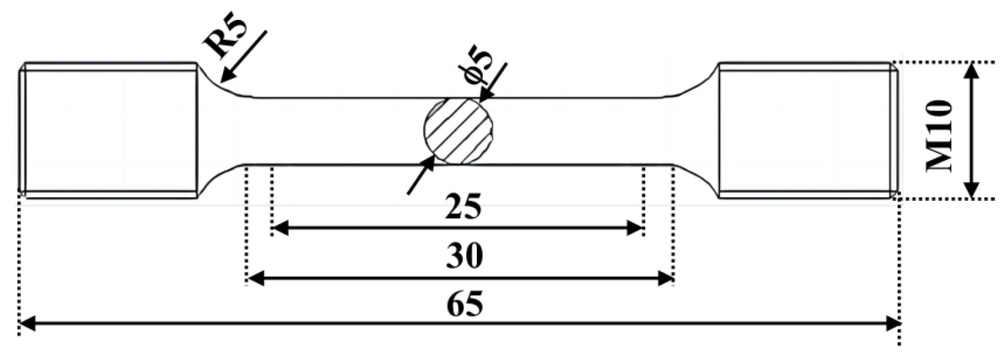
2. Materials and Methods

The nominal chemical composition of FGH96 powder metallurgy superalloy is listed in Table 1.
The alloy powders were atomized under an argon atmosphere and then encapsulated into a stainless-steel jacket for hot isostatic pressing and hot extrusion deformation. Finally, a disc component was prepared by forging. The samples used for the inertia friction welding experiments were cut from the forged piece of FGH96 powder metallurgy superalloy and had an outer diameter of 120 mm and a thickness of 8 mm. The samples to be inertia friction welded were subjected to a standard solution heat treatment at 1150 °C for 2 h, and then a semi-aging heat treatment at 760 °C for 8 h. Inertia friction welding was employed for butt welding of ring components. The welding machine was an HFW-IFW-6000 (Harbin Welding Institute Limited Company, Harbin, China). The welding parameters were as follows: a revolving speed of 620 ft/min, an axial pressure of 1900 PSI, a moment of inertia of 8081 ft2, and a shortening amount of the welding axial length of 2.60 mm. A second semi-aging heat treatment at 760 °C for 8 h was conducted after the inertia friction welding. It should be noted that the time of semi-aging heat treatment is half that of the standard aging time, hence the name. In fact, other parts except for the inertia friction welded joint experienced a standard solution (1150 °C, 2 h) + aging (760 °C, 16 h) heat treatment. This uncommon process is mainly used to meet the requirements of industrial applications, and it is expected to have the following three advantages. Firstly, it can reduce the time- and process-cost, which is very important from an industrial perspective. Secondly, it will not affect the microstructure of the base metals. Thirdly, it can eliminate the residual stress and optimize the microstructure of inertia friction welded joints to the maximum extent.
X-ray diffraction (XRD) was used to check the axial residual stress distribution of different locations at the center of the welded joint before and after heat treatment. A good surface flatness for both the as-welded sample and semi-aged heat-treated sample was obtained by grinding with a grinding wheel. After grinding, electrochemical polishing was carried out in a solution of 45 mL lactic acid + 45 mL methanol + 10 mL hydrochloric acid with a voltage of 6 V at room temperature to remove the ground layer. The XRD diffractometer used was a Proto-iXRD (Proto Manufacturing Ltd., Ontario, ON, Canada), and the test parameters used are shown in Table 2.
Samples for microstructure observation were sliced from different positions of the as-welded and semi-aged heat-treated samples, and then hot mounted, ground with 180-mesh, 400-mesh, 800-mesh, and 1200-mesh sandpapers in sequence, and finally polished with a polishing machine to obtain a mirror surface without scratches. Then the prepared samples were etched with Kalling’s etchant (10 g CuCl2 + 250 g HCl + 50 g ethanol) for 30 s. Optical microscopy (OM, OLYMPUS DP2-TWAIN, Tokyo, Japan) and scanning electron microscopy (SEM, JEOL JSM-7800 F, Tokyo, Japan) were used to observe the macro morphology and microstructure characteristics of the inertia friction welded joints before and after semi-aging heat treatment. In addition, electron backscattering diffraction (EBSD, Aztec HKL Symmetry S2, Oberkochen, Germany) analysis was used to identify the sub-grain boundary for the as-welded sample.
An HXD-1000TMC/LCD Vickers microhardness tester (Shanghai Taiming Optical Instrument Co., Ltd., Shanghai, China) was used to measure the Vickers micro-hardness at different locations of the welded joints pre- and post-heat treatment. The distance between hardness test points was about 0.20 mm, and a load of 200 gf was applied for 10 s.
The mechanical property test was performed according to GB/T 4338-2006. The dimensions of the tensile samples are shown in Figure 1. The welding line was located at the center of the gauge length section when sampling. The samples were polished after lathe machining, with the surface roughness being less than 0.80 μm. The tensile test was carried out at room temperature on a Z100SH electronic universal testing machine (ZwickRoell, Ulm, Germany), with a tensile rate of 1 mm/min. Three samples were measured for each group, and then, the average values were taken as mechanical property data. After the tensile test was completed, the tensile fracture surface was observed via SEM to analyze the fracture failure mechanism.

3. Results and Discussion

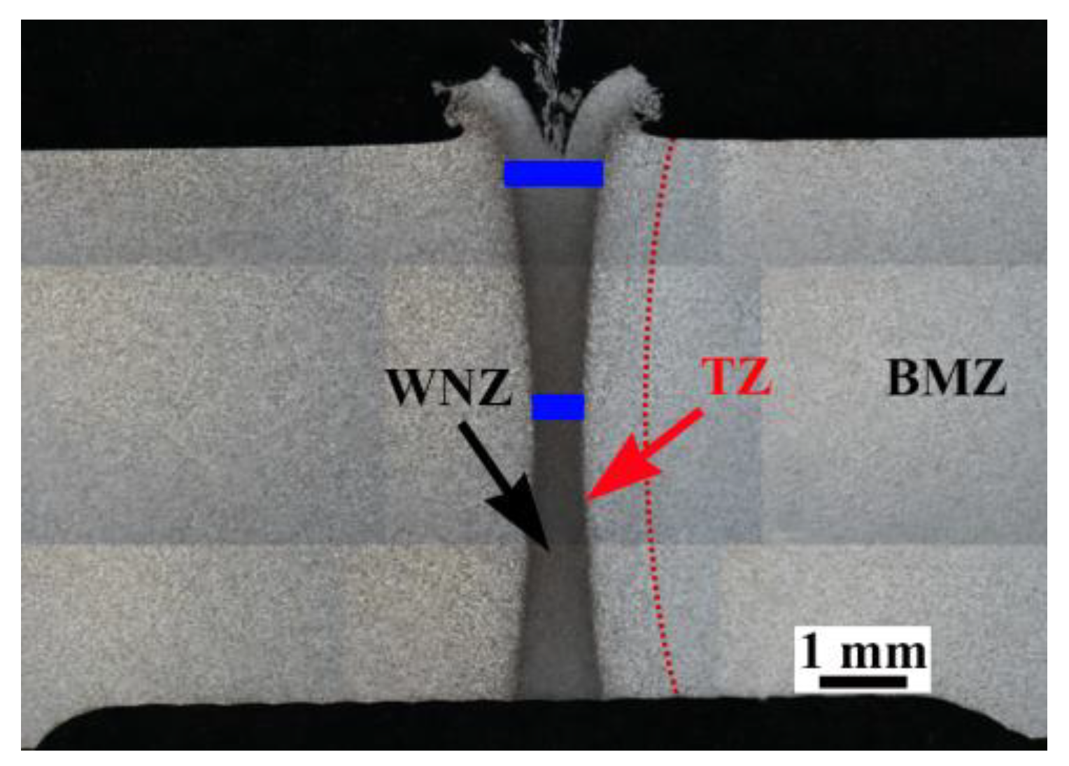
3.1. Morphology of Welded Joints
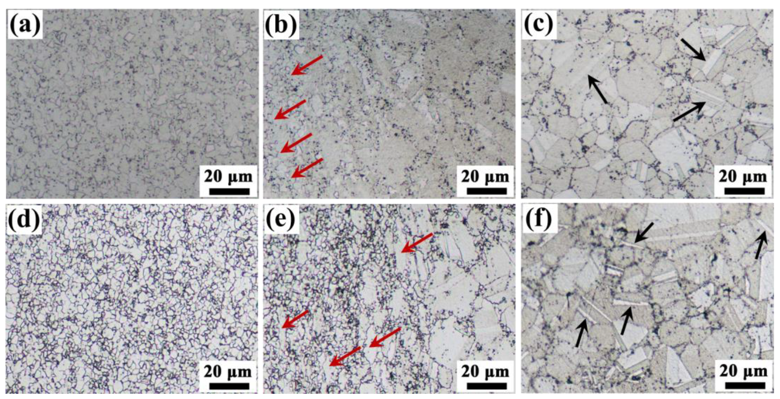
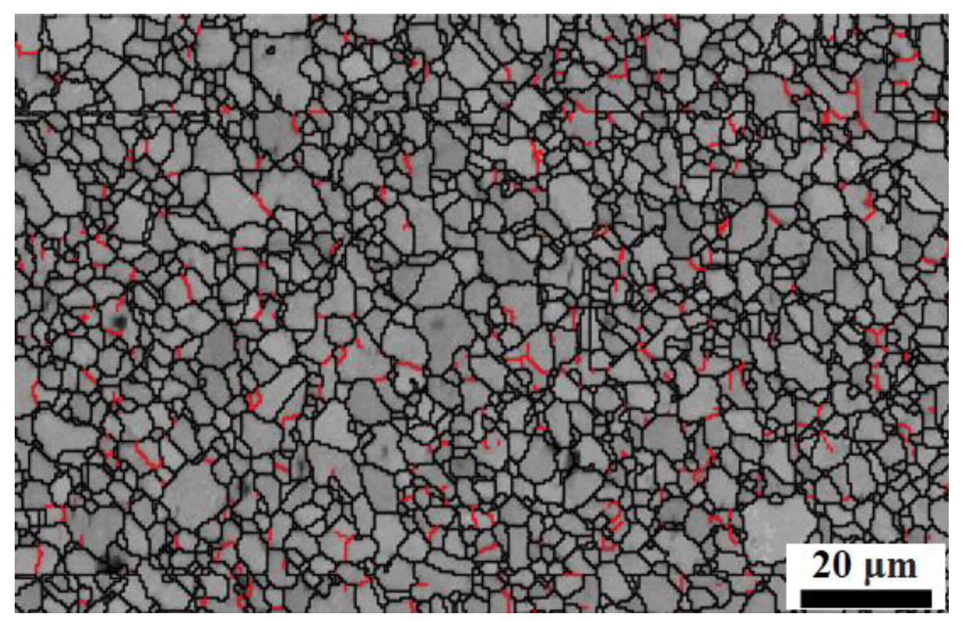
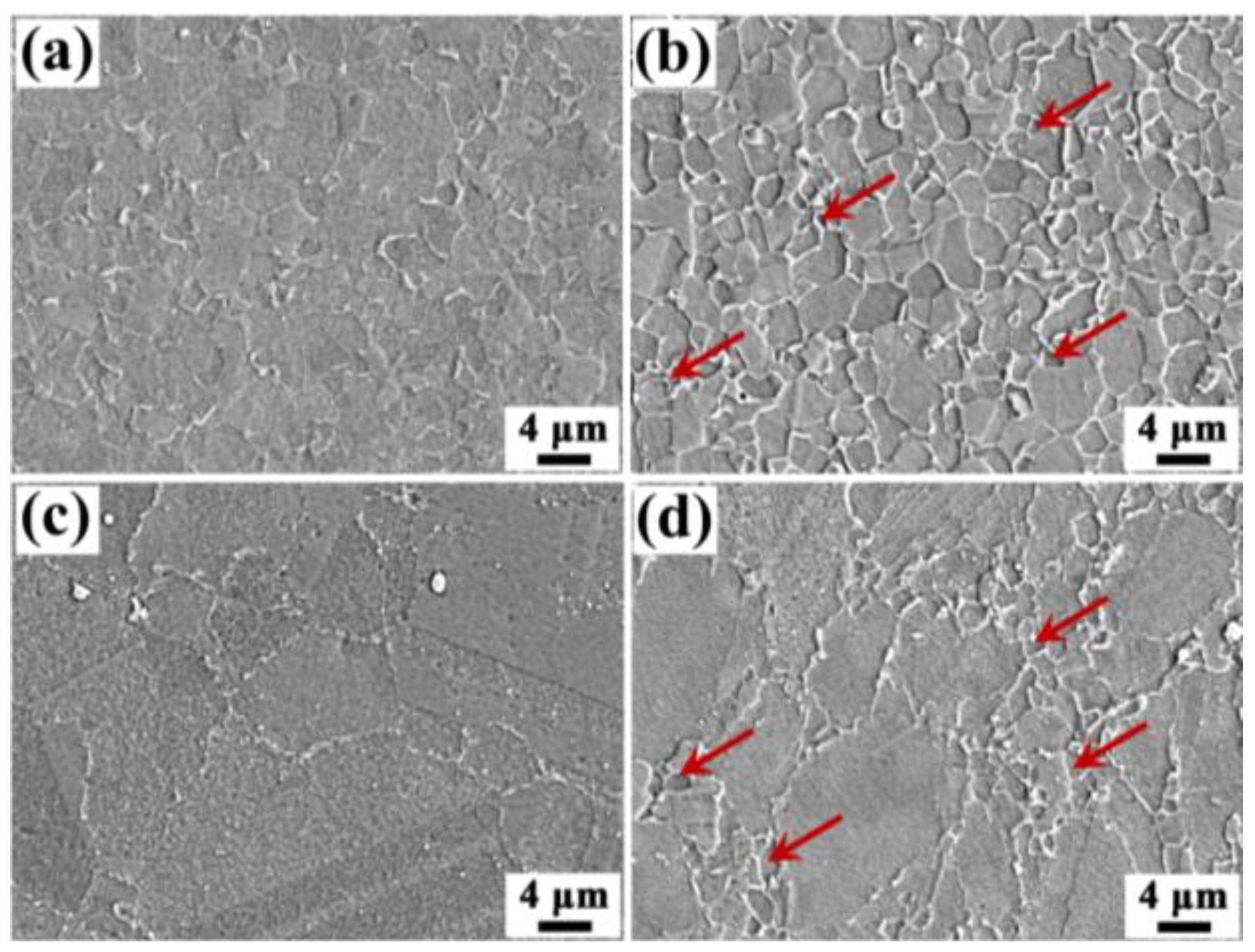
Figure 2 shows the typical cross-sectional morphology of the inertia friction welded FGH96 powder metallurgy joint. When optimized inertia friction welding parameters are selected, the as-welded joint shows typical bifurcation and flash characteristics [35,36]. The minimum and maximum widths of the weld nugget zone (WNZ) are 0.63 mm and 1.22 mm, as shown by the short, thick blue lines in Figure 2, respectively. Since the base materials on both sides of the welding pieces are the same, the whole weld zone and weld flash created by the discharge of contacting metals under axial pressure are symmetrical as a result of friction. In addition, it can be seen from the figure that there are no obvious welding defects, such as inclusions or cracks, in the as-welded joint. The research results of Masoumi et al. [36] show that optimized inertia friction welding process parameters are conducive to the full extrusion of the faying surfaces to be welded, and then the oxides in the weld joint can be removed.

3.2. Microstructure

Due to the large temperature gradient experienced by the entire welded joint during the inertia friction welding process, the microstructure of the inertia friction welded joint shows three typical zones: the weld nugget zone (WNZ), the transition zone (TZ), and the base metal zone (BMZ), as shown in Figure 2. The microstructures at different zones of the inertia friction welded joint are shown in Figure 3a–c. The microstructure in the WNZ (Figure 3a) embodies the characteristics of extremely fine equiaxed grains resulting from complete recrystallization [37]. There is a large shear deformation and some axial shortening deformation in the WNZ. This large plastic deformation results in many sub-grain boundaries as crystal nuclei for recrystallization in the WNZ. Under the action of high temperature during the process of welding and rapid cooling after welding, the grains are formed by recrystallization but haven’t grown yet [37]. Therefore, many fine equiaxed grains are formed and the average grain size in the WNZ in this study is 4.18 ± 0.20 μm, which is far smaller than that of the base metal. The TZ (Figure 3b) contains the heat-force-affected zone and the heat-affected zone. In the heat-force-affected zone near the WNZ, the microstructure shows complex features. It is composed of fine equiaxed fine grains and deformed grains stretching along the extrusion direction (see the red arrow in Figure 3b). In this zone, only partial recrystallization occurs during the welding process due to the decrease in temperature and the weakening of plastic deformation. In the heat-affected zone adjacent to the BMZ, the grain size is slightly larger than that of the base metal, which indicates that the grains grow under the action of high temperature. Large equiaxed grains with a large number of twin structures inside the grain (see the black arrow in Figure 3c) can be found in the BMZ, shown in Figure 3c. The grain size in this zone is relatively uniform.
Noticeably, the grain boundaries in the WNZ for the as-welded sample seem unclear. And some sub-grain boundaries still exist in the WNZ for the as-welded sample, indicated by the red lines in Figure 4. This may be because the energy accumulated by high temperature and plastic deformation in the weld zone under the inertia friction welding parameters used in this study is inadequate to fully complete the recrystallization process during the inertia friction welding.
The microstructures at different zones of the inertia friction welded joint after semi-aging heat treatment are shown in Figure 3d–f. It can be clearly seen that the microstructure of the entire inertia friction welded joint still presents three typical zones. However, compared to the as-welded sample, the grain boundaries in the WNZ (Figure 3d) and the TZ (Figure 3e) are very clear, and a large number of very fine grains of <2.00 μm are observed in the semi-aging heat-treated sample shown by the red arrows in Figure 5b,d. It is the formation of the finer grains that causes the decrease in the average grain size. The average grain size in the WNZ was 2.88 ± 0.13 μm, assessed using the grain intercept count method. The formation of finer grain indicates that the semi-aging heat treatment after welding further facilitates recrystallization. However, the semi-aging heat treatment after welding has no impact on the microstructure of the base metal (Figure 3f).
In addition, the post-weld heat-treated sample has actually gone through a complete standard heat treatment. It is reasonable to believe that the γ′ phases can be precipitated in the inertia friction welded joint [4,14] although the specifics of the γ′ precipitated phases have not been characterized in this paper.

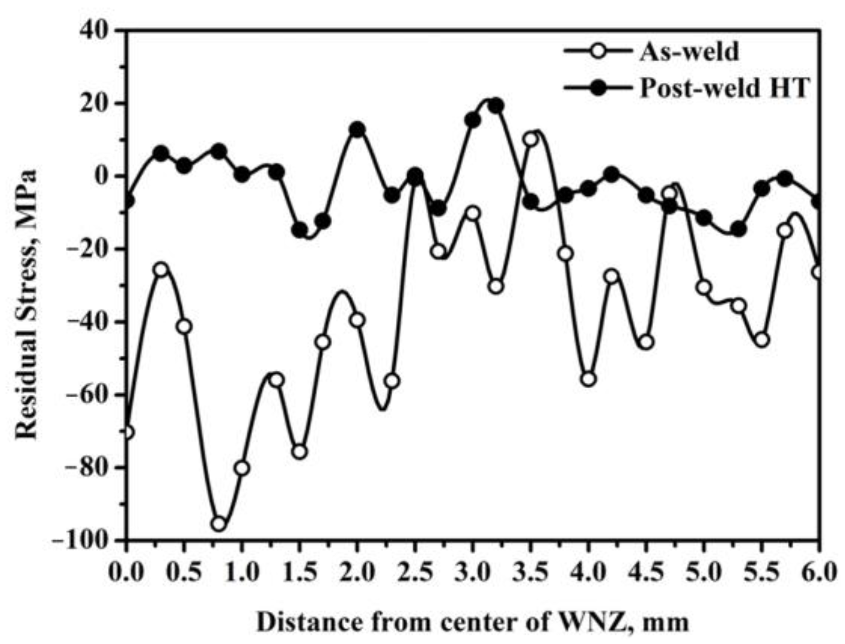
3.3. Distribution of Residual Stress

Figure 6 shows the axial residual stress distribution of different locations at the center of inertia friction welded joints of FGH96 powder metallurgy superalloy before and after heat treatment. Under the as-welded condition, the stress distribution of the entire inertia friction welded joint shows large fluctuations. The residual stress values in the WNZ and the TZ are much larger than that in the BMZ. In particular, the residual stress value near the TZ reaches a maximum, i.e., approximately −96 MPa. The negative value of residual stress represents the compressive stress, which exists along the axial direction at the center of the inertia friction welded joint [30]. The residual stress is associated with the welded microstructures in the inertia friction welded joint. In the WNZ, the grains are very fine and the residual stress generated by the large plastic deformation can be released due to the obvious recrystallization at high temperatures. However, in the TZ, only partial recrystallization occurs due to the relatively low temperature, which leads to the release of a portion of the residual stress. Thus, it has the largest residual stress value in the TZ.
After the post-weld semi-aging heat treatment, the residual stresses in the WNZ and the TZ are largely consistent with that in the BMZ. This indicates that the semi-aging heat treatment after inertia friction welding can effectively relieve the residual stress through further recrystallization and the re-precipitation of γ′ phases. In addition, it can also be seen that there is still slight residual stress in the BMZ for the as-welded sample. This can be attributed to the fact that the residual stress of the forging piece has not been completely eliminated by the adoption of a standard solution heat treatment at 1150 °C for 2 h and then a semi-aging heat treatment at 760 °C for 8 h. However, the slightly residual stress in the base metal can be further relieved through post-weld semi-aging heat treatment.

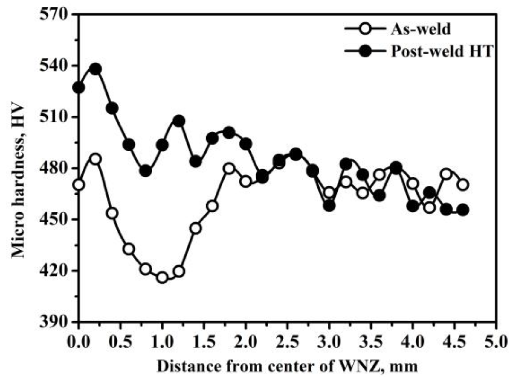
3.4. Distribution of Micro-Hardness

Figure 7 shows the micro-hardness profiles of the inertia friction welded joint across the weld line as a function of axial position for the as-welded and semi-aging samples. A typical hardness trough can be observed for the as-welded sample, and the trough value is about 415 HV located at 1.00 mm from the center of the WNZ. The micro-hardness values suited at the center of WNZ and 2.00 mm from the center of WNZ are about 482 HV, which is slightly higher than that of the base metal (470 ± 15 HV). The higher micro-hardness value at the center of the WNZ is always attributed to the grain refinement caused by dynamic recrystallization and the precipitation of a large number of re-precipitated γ′ phases [14]. Meanwhile, the higher micro-hardness located at 2.00 mm from the center of the WNZ results from the work hardening effect, which is caused by a large plastic deformation that occurred in the TZ. However, the minimum micro-hardness value is observed suited at 1.00 mm from the center of the WNZ, which is much lower than that of the base metal.
The research results of Zhang et al. [14] indicate that a hardness trough occurring approximately 0.1–0.2 mm from the WL was bounded by two peaks situated at 0 and 0.5 mm from the WL. However, even at the hardness trough, the micro-hard value is also higher than that of the base metal. The higher hardness of the WNZ is the result of the grain refinement and re-precipitation of the γ′ phase, and the decrease in the hardness of the TZ is attributed to the fact that only partial recrystallization occurs in the TZ, and no fine γ′ phase has been re-precipitated [14]. However, the research results of Yang et al. [19] show that the hardness value of the WNZ is much lower than that of the BMZ, and the authors believe that the hardness decreases due to the dissolution of the γ′ phase. Meanwhile, there is a micro-hardness trough in the middle of the heat-force affected zone, whose micro-hardness value is very lower than that of the BMZ due to grain growth and the precipitation of a small amount of γ′ phase. M. Preuss et al. [34] show that the driving force of strengthening phase precipitation at the center of the WL is greater than that at 1.00 mm from the WL, and a high level of γ′ phase would be obtained close to the WL, which leads to a relatively high micro-hardness value. The change in micro-hardness always reflects the change in microstructure. The inconsistency in the variation in the micro-hardness with the distance from the WNZ indicates the complex microstructure of inertia friction welded joints. In this study, the trough micro-hardness observed at the TZ for the as-weld sample is similar to the results of Yang et al. [23], and the decrease in micro-hardness would be attributed to grain growth and precipitation of only a small amount of γ′ phase.
After the inertia friction welded joint experiences post-weld semi-aging heat treatment, the pattern of the micro-hardness of the weld joint shows a significant change. On the one hand, the micro-hardness value of the WNZ rises significantly to 530 HV, which is 60 HV higher than that of the BMZ. On the other hand, the micro-hardness trough that existed in the TZ of the as-weld sample seems to disappear. The micro-hardness value in the TZ becomes more uniform and is slightly higher than that of the base metal. The increase in micro-hardness can be attributed to two reasons. Firstly, the semi-aging heat treatment can further facilitate recrystallization in the WNZ and TZ, which gives rise to the finer grain (Figure 3d). Secondly, the semi-aging heat treatment derives from the standard heat treatment, which includes solution treatment and aging treatment. The aim of aging treatment is to promote the precipitation of γ′ phase. Although the processing time of the semi-aging treatment is half of that of the aging treatment in the standard regime, the re-precipitation of γ′ phase is believed to have occurred. The combination of finer grains and precipitation of γ′ phase leads to an increase in the micro-hardness.
The micro-hardness values of the BMZ in the as-weld sample and the semi-aging sample do not show any significant difference, with a value of 470 ± 15 HV. This further demonstrates that semi-aging heat treatment has little impact on the microstructure of the BMZ.

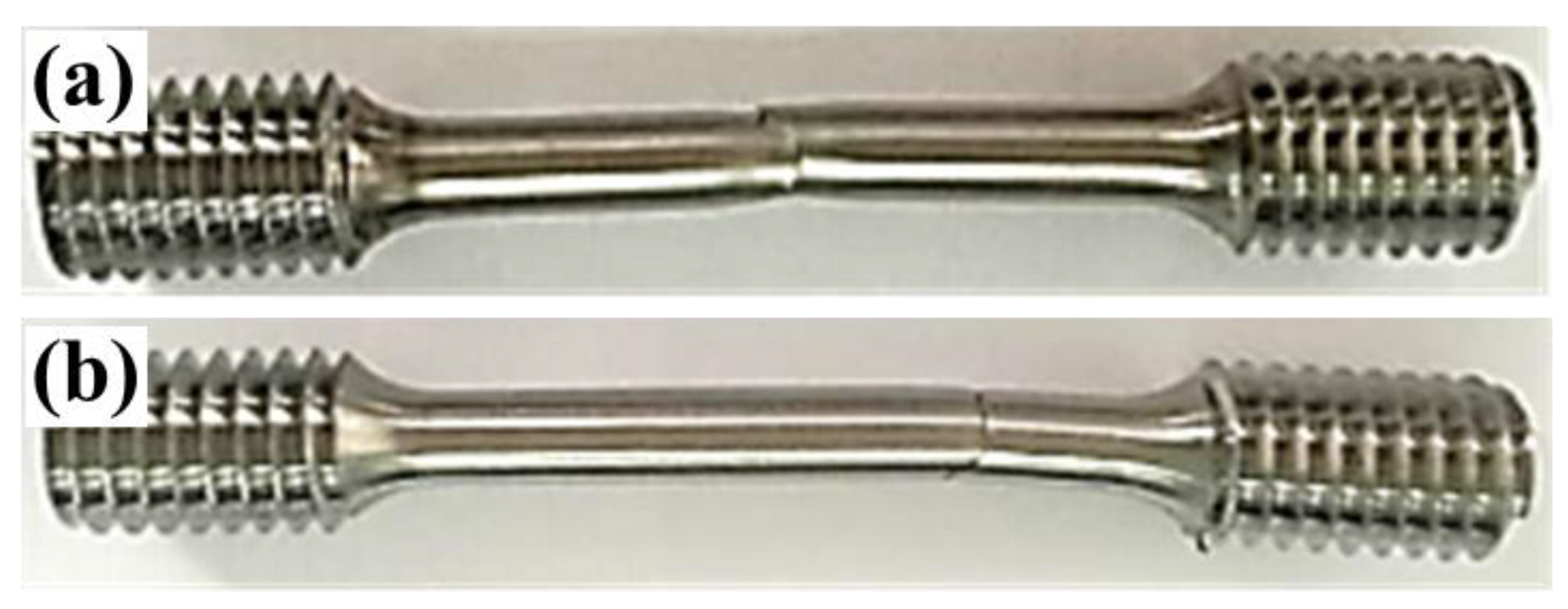
3.5. Mechanical Properties and Failure Behavior

Figure 8 shows the tensile failure locations of inertia friction welded joints at room temperature for the as-welded and semi-aging heat-treated samples. It is evident that the tensile failure was located in the WNZ for the as-welded sample. This is consistent with reported results, and the author attributes this to complete γ′ phase dissolution, which reduces the strength of the inertia friction welded joint [23]. However, the tensile failure location was transformed to the BMZ far away from the weld zone for the semi-aging heat-treated sample. This indicates that the strength of the inertia friction welded joint after semi-aging heat treatment is significantly improved and exceeds that of the base metal.
The room temperature tensile properties of the as-welded and semi-aging heat-treated samples are summarized in Figure 9. The as-welded sample presented an ultimate tensile strength (σuts) of 1500 MPa, a yield strength (σ0.2) of 1151 MPa, and an elongation at break (εab) of 14.74%. Since the failure occurred in the weld zone (shown in Figure 8), the tensile properties of the as-welded sample are determined by the microstructure and residual stress state of the inertia friction welded joint. Both the strength and the elongation of the semi-aging heat-treated sample were improved. The σuts, σ0.2, and εab reached 1618 MPa, 1268 MPa, and 19.6%, which were 7.8%, 10.2%, and 33.1% higher than that of the as-welded sample, respectively. The results for the room temperature tensile properties are consistent with that of the micro-hardness shown in Figure 7.
Figure 10 shows the tensile fracture morphology of the as-welded and semi-aging heat-treated samples at room temperature. For the as-welded sample, a shear fracture mode can be observed (Figure 9a and Figure 10a), whereas, a normal fracture mode can be found for the semi-aging heat-treated sample (Figure 9b and Figure 10b). However, no matter whether as-welded or semi-aging heat-treated, only two macro characteristic zones can be distinguished on the tensile fracture surface, i.e., the shear lip zone (shown by the thick red lines in Figure 10a,b) and the fibrous zone. A radical zone cannot be observed.
Figure 11 shows the fractography of room-temperature tensile-tested samples. Some shallow dimples with different sizes (shown by the red arrows in Figure 11a,b) and tearing ridges (shown by the yellow arrows in Figure 11a,b) can be observed in the fibrous zone for both as-welded sample and semi-aging heat-treated sample). The features of fracture morphology indicate that the inertia friction welded joint mainly presents a ductile mode of fracture in all samples. Noticeably, fractured particles (shown by the green circles in Figure 11b) were also observed in the fracture surface of the semi-aging heat-treated sample. Whereas, no such broken particles were found in the as-welded sample. This indicates that the fracture origins of the pre- and post-heat-treated samples are different. For the as-welded sample, the plastic deformation mainly occurs in the WNZ due to the low strength of the WNZ, resulting in dislocation pileup and cracks. For the semi-aging heat-treated sample, the plastic deformation occurs in the BMZ because of the higher strength in the WNZ, and the fracture of some inclusions induces cracks.

4. Conclusions

Forged pieces of FGH96 powder metallurgy superalloy were subjected to a standard solution heat treatment at 1150 °C for 2 h and then a semi-aging heat treatment at 760 °C for 8 h. They were then inertia friction welded, before a second semi-aging heat treatment at 760 °C for 8 h was applied to the inertial friction welded joint. The effect of semi-aging heat treatment on the microstructure, residual stress, micro-hardness, and room temperature mechanical properties have been studied. The main conclusions are as follows:
(1)
After the semi-aging heat treatment, the grain size and grain boundary morphology of the base metal shows no changes. However, the semi-aging heat treatment can further facilitate recrystallization in the WNZ and TZ, which reduces the average grain size in the WNZ from 4.18 μm to 2.88 μm.
(2)
A large residual stress of up to −96 MPa existed in the inertia friction welded FGH96 joint. However, semi-aging heat treatment after welding (760 °C, 8 h) can effectively eliminate the residual stress in the WNZ and TZ, making the overall residual stress of the welded sample uniform.
(3)
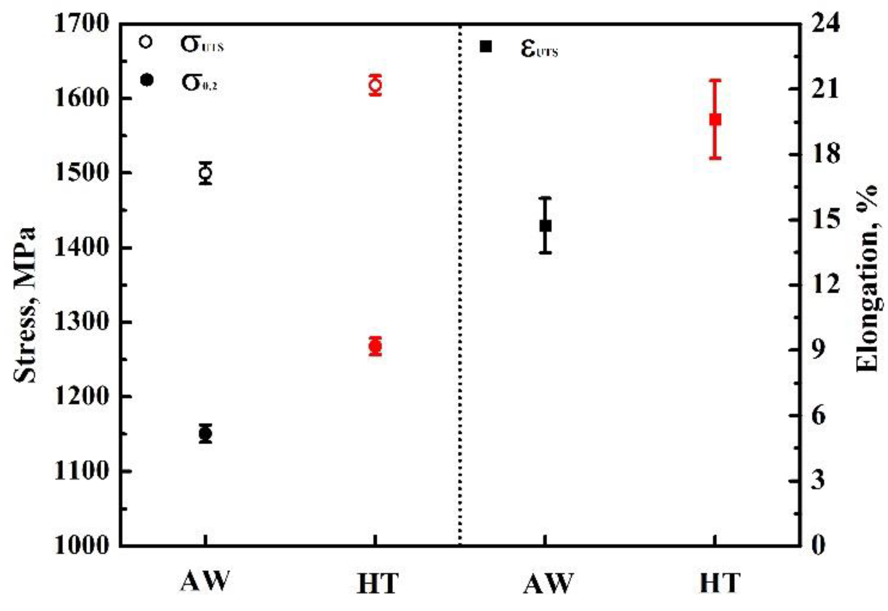
Post-weld semi-aging heat treatment increased the micro-hardness of the WNZ from 470 HV to 530 HV. Meanwhile, post-weld semi-aging heat treatment also increased the room temperature tensile strength, which leads to the failure location relocating to the base metal.

Author Contributions

Conceptualization, X.H., G.Z., Q.T. and B.S.; methodology, X.H. and G.Z.; validation, X.H. and Q.T.; formal analysis, X.H. and Q.T.; investigation, X.H.; resources, X.H.; data curation, X.H. and Q.T.; writing—original draft preparation, X.H.; writing—review and editing, G.Z. and Q.T.; visualization, X.H. and Q.T.; supervision, G.Z. and B.S.; project administration, X.H., G.Z. and B.S.; funding acquisition, B.S. All authors have read and agreed to the published version of the manuscript.

Funding

This research received no external funding.

Institutional Review Board Statement

Not applicable.

Data Availability Statement

Not available.

Acknowledgments

The authors gratefully acknowledge the technical and material support of AECC Commercial Aircraft Engine Co., Ltd.

Conflicts of Interest

The authors declare no conflict of interest.

References

  1. Liu, Y.H.; Wang, M.; Sun, P.W.; Yang, G.; Song, W.J.; Wang, X.F. Effect of solution treatment on microstructure evolution of a powder metallurgy nickel based superalloy with incomplete dynamic recrystallization microstructure. Metals 2023, 13, 239. [Google Scholar] [CrossRef]
  2. Lin, C.H.; Yu, L.W.; Zeng, J.L.; Wu, H.B.; Guo, X.J.; Liu, J.X.; Zhang, Y.K. Experimental study on FGH95 superalloy turbine disk joint material by oblique laser shock processing. Metals 2021, 11, 1770. [Google Scholar] [CrossRef]
  3. Xu, Y.M.; Zhang, S.M.; He, T.P.; Liu, X.L.; Chang, X.Y. Prediction of low-cycle crack initiation life of powder superalloy FGH96 with inclusions based on damage mechanics. Trans. Nonferr. Met. Soc. China 2012, 32, 895–907. [Google Scholar] [CrossRef]
  4. Peng, Z.C.; Zou, J.W.; Wang, X.Q. Microstructural characterization of dislocation movement during creep in powder metallurgy FGH96 superalloy. Mater. Today Commun. 2020, 25, 101361. [Google Scholar] [CrossRef]
  5. Shi, Y.; Yang, X.G.; Yang, D.D.; Shi, D.Q.; Miao, G.L. Evaluation of the influence of surface crack-like defects on fatigue life for a P/M nickel-based superalloy FGH96. Int. J. Fatigue 2020, 137, 105639. [Google Scholar] [CrossRef]
  6. Singh, A.R.P.; Nag, S.; Chattopadhyay, S.; Ren, Y.; Tiley, J.; Viswanathan, G.B.; Fraser, H.L.; Banerjee, R. Mechanisms related to different generations of γ′ precipitation during continuous cooling of a nickel base superalloy. Acta Mater. 2013, 61, 280–293. [Google Scholar] [CrossRef]
  7. Li, L.; Liu, F.R.; Nie, S.J.; Wang, Q.; Zhao, R.X.; Zhang, Y.Z.; Feng, H.Y.; Lin, X. Effect of thermal cycling on grain evolution and micro-segregation in selective laser melting of FGH96 superalloy. Metals 2023, 13, 121. [Google Scholar] [CrossRef]
  8. Liu, W.; Liu, Z.L.; Zhang, H.; Ruan, J.J.; Huang, H.L.; Zhou, X.; Meng, F.C.; Zhang, S.Z.; Jiang, L. Hot deformation behavior and new grain size model of hot extruded FGH4096 superalloy during hot compression. J. Alloys Compd. 2023, 938, 168574. [Google Scholar] [CrossRef]
  9. Liu, A.; Zhang, Y.T.; Wang, X.S.; Xu, W.; Zhang, Y.; He, Y.H. Evaluation of the influences of the stress ratio, temperatures, and local microstructure on small fatigue crack propagation behavior of the FGH96 superalloy. Int. J. Fatigue 2023, 171, 107573. [Google Scholar] [CrossRef]
  10. Xu, Y.M.; Chen, H.; Zhang, S.M.; He, T.P.; Liu, X.R.; Chang, X.Y. An experimental study on low-cycle fatigue crack initiation life prediction of powder superalloy FGH96 based on the Manson-Coffin and damage mechanics methods. Metals 2021, 11, 489. [Google Scholar] [CrossRef]
  11. Zhang, M.J.; Li, F.G.; Yuan, Z.W.; Li, J.; Wang, S.Y. Effect of heat treatment on the micro-indentation behavior of powder metallurgy nickel based superalloy FGH96. Mater. Design 2013, 49, 705–715. [Google Scholar] [CrossRef]
  12. Preuss, M.; Withers, P.J.; Pang, J.W.L.; Baxter, G.J. Inertia welding nickel-based auperalloy: Part II. Residual stress characterization. Metall. Mater. Trans. A 2002, 33, 3227–3234. [Google Scholar] [CrossRef]
  13. Preuss, M.; Withers, P.J.; Pang, J.W.L.; Baxter, G.J. Inertia welding nickel-based superalloy: Part I. Metallurgical characterization. Metall. Mater. Trans. A 2002, 33, 3215–3225. [Google Scholar] [CrossRef]
  14. Zhang, C.; Shen, W.F.; Zhang, L.W.; Xia, Y.N.; Li, R.Q. The microstructure and gamma prime distributions in inertia friction welded joint of P/M superalloy FGH96. J. Mater. Eng. Perform. 2017, 26, 1581–1588. [Google Scholar] [CrossRef]
  15. Wang, Z.T.; Huang, S.; Zhang, W.Y.; Zhang, B.J.; Ning, Y.Q. Microstructure characterization and mechanical property of the GH4065A superalloy inertia friction welded joints. Metals 2022, 12, 1390. [Google Scholar] [CrossRef]
  16. Li, Z.S.; Liu, Z.T.; Chen, D.J.; Mo, F.; Fu, Y.F.; Dai, Y.; Wu, X.; Cong, D.L. Study of microstructure and properties of aluminum/steel inertia radial friction welding. Metals 2022, 12, 2023. [Google Scholar] [CrossRef]
  17. Attallah, M.M.; Preuss, M. 2-Inertia friction welding (IFW) for aerospace applications. In Woodhead Publishing Series in Welding and Other Joining Technologies, Welding and Joining of Aerospace Materials, 2nd ed.; Chaturvedi, M.C., Ed.; Woodhead Publishing: Winnipeg, MB, Canada, 2012; pp. 21–74. [Google Scholar]
  18. Raimondi, L.; Bennett, C.J.; Axinte, D.; Gameros, A.; Stevens, P.A. Development of a novel monitoring system for the in-process characterisation of the machine and tooling effects in Inertia Friction Welding (IFW). Mech. Syst. Signal Process. 2021, 156, 107551. [Google Scholar] [CrossRef]
  19. Cam, G.; Kocak, M. Progress in joining of advanced materials. Int. Mater. Rev. 1998, 43, 1–33. [Google Scholar] [CrossRef]
  20. Maalekian, M.; Kozeschnik, E.; Brantner, H.P.; Cerjak, H. Comparative analysis of heat generation in friction welding of steel bars. Acta Mater. 2008, 56, 2843–2855. [Google Scholar] [CrossRef]
  21. Karadge, M.; Grant, B.; Withers, P.J.; Baxter, G.; Preuss, M. Thermal relaxation of residual stresses in nickel-based superalloy inertia friction welds. Metall. Mater. Trans. A 2011, 42, 2301–2311. [Google Scholar] [CrossRef]
  22. Pang, J.W.L.; Preuss, M.; Withers, P.J.; Baxter, G.J.; Small, C. Effects of tooling on the residual stress distribution in an inertia weld. Mater. Sci. Eng. A 2003, 356, 405–413. [Google Scholar] [CrossRef]
  23. Yang, J.; Li, J.L.; Jin, F. Effect of welding parameters on high-temperature tensile and fatigue properties of FGH96 inertia friction welded joints. Weld. World 2019, 63, 1033–1053. [Google Scholar] [CrossRef]
  24. Bennett, C.J.; Hyde, T.H.; Shipway, P.H. A transient finite element analysis of thermoelastic effects during inertia friction welding. Comp. Mater. Sci. 2011, 50, 2592–2598. [Google Scholar] [CrossRef]
  25. Grant, B.; Preuss, M.; Withers, P.J.; Baxter, G.; Rowlson, M. Finite element process modelling of inertia friction welding advanced nickel-based superalloy. Mater. Sci. Eng. A 2009, 513–514, 366–375. [Google Scholar] [CrossRef]
  26. Chamanfar, A.; Jahazi, M.; Cormier, J. A review on inertia and linear friction welding of Ni-based superalloys. Metall. Mater. Trans. A 2015, 46, 1639–1669. [Google Scholar] [CrossRef]
  27. Senkov, O.N.; Mahaffey, D.W.; Semiatin, S.L. A comparison of the inertia friction welding behavior of similar and dissimilar Ni-based superalloys. Metall. Mater. Trans. A 2018, 49, 5428–5444. [Google Scholar] [CrossRef]
  28. Huang, Z.W.; Li, H.Y.; Baxter, G.; Bray, S.; Bowen, P. Electron microscopy characterization of the weld line zones of an inertia friction welded superalloy. J. Mater. Process. Technol. 2011, 211, 1927–1936. [Google Scholar] [CrossRef]
  29. Nie, L.F.; Zhang, L.W.; Zhu, Z.; Xu, W. Microstructure evolution modeling of FGH96 superalloy during inertia friction welding process. Finite Elem. Anal. Des. 2014, 80, 63–68. [Google Scholar] [CrossRef]
  30. Iqbal, N.; Rolph, J.; Moat, R.; Hughes, D.; Hofmann, M.; Kelleher, J.; Baxter, G.; Withers, P.J.; Preuss, M. A comparison of residual stress development in inertia friction welded fine grain and coarse grain nickel-base superalloy. Metall. Mater. Trans. A 2011, 42, 4056–4063. [Google Scholar] [CrossRef]
  31. Iracheta, O.; Bennett, C.J.; Sun, W. A sensitivity study of parameters affecting residual stress predictions in finite element modelling of the inertia friction welding process. Int. J. Solids Struct. 2015, 71, 180–193. [Google Scholar] [CrossRef]
  32. Akarapu, S.; Hirth, J.P. Dislocation pile-ups in stress gradients revisited. Acta Mater. 2013, 61, 3621–3629. [Google Scholar] [CrossRef]
  33. Damodaram, R.; Ganesh Sundara Raman, S.; Satyanarayana, D.V.V.; Madhusudhan Reddy, G.; Prasad Rao, K. Hot tensile and stress rupture behavior of friction welded alloy 718 in different pre-and post-weld heat treatment conditions. Mater. Sci. Eng. A 2014, 612, 414–422. [Google Scholar] [CrossRef]
  34. Preuss, M.; Withers, P.J.; Baxter, G.J. A comparison of inertia friction welds in three nickel base superalloys. Mater. Sci. Eng. A 2006, 437, 38–45. [Google Scholar] [CrossRef]
  35. Li, W.Y.; Wang, F.F. Modeling of continuous drive friction welding of mild steel. Mater. Sci. Eng. A 2011, 528, 5921–5926. [Google Scholar] [CrossRef]
  36. Masoumi, F.; Shahriari, D.; Monajati, H.; Cormier, J.; Flipo, B.C.D.; Devaux, A.; Jahazi, M. Linear friction welding of AD730™ Ni-base superalloy: Process-microstructure-property interactions. Mater. Design 2019, 183, 108117. [Google Scholar] [CrossRef]
  37. Tabaie, S.; Rézaï-Aria, F.; Flipo, B.C.D.; Jahazi, M. Grain size and misorientation evolution in linear friction welding of additively manufactured IN718 to forged superalloy AD730™. Mater. Charact. 2021, 171, 110766. [Google Scholar] [CrossRef]
Figure 1. Dimensions of samples for the tensile property test at room temperature (Unit: mm).
Metals 13 00632 g001
Figure 2. Typical cross-sectional flash shapes of the inertia friction welded FGH96 joint, indicating the different zones.
Metals 13 00632 g002
Figure 3. Microstructures in different zones of the inertia friction welded joint: (ac) as-welded sample; (df) semi-aging heat-treated sample.
Metals 13 00632 g003
Figure 4. EBSD of WNZ for as-welded sample, indicating the existence of sub-grain boundaries shown by red lines (2~15°).
Metals 13 00632 g004
Figure 5. Morphology of WNZ and heat-affected zone, indicating that heat treatment can further facilitate recrystallization: (a) WNZ for as-welded sample; (b) WNZ for semi-aging heat-treated sample; (c) HAZ for as-welded sample; (d) HAZ for semi-aging heat treated sample.
Metals 13 00632 g005
Figure 6. Axial residual stress distribution in inertia friction welded FGH96 joint.
Metals 13 00632 g006
Figure 7. Micro-hardness distribution in inertia friction welded FGH96 joint.
Metals 13 00632 g007
Figure 8. Tensile failure locations of the inertia friction welded joint: (a) as-welded sample; (b) semi-aging heat-treated sample.
Metals 13 00632 g008
Figure 9. Room temperature tensile performance of inertia friction welded joints before and after semi-aging heat treatment.
Metals 13 00632 g009
Figure 10. Macro fracture morphology at room temperature: (a) as-welded sample; (b) semi-aging heat-treated sample.
Metals 13 00632 g010
Figure 11. Fractographs of room temperature tensile tests samples: (a) as-welded sample; (b) semi-aging heat-treated sample.
Metals 13 00632 g011
Table 1. Nominal chemical composition of FGH96 (wt%).
CCrCoMoWAlTiNbNi
0.02~0.0515.50~16.5012.50~13.503.80~4.203.80~4.202.00~2.403.50~3.900.60~1.00Bal.
Table 2. XRD parameters for the residual stress test.
Target MaterialVoltage, KVCurrent, mADiffraction Crystal Face
Mn204(311)152–162
Disclaimer/Publisher’s Note: The statements, opinions and data contained in all publications are solely those of the individual author(s) and contributor(s) and not of MDPI and/or the editor(s). MDPI and/or the editor(s) disclaim responsibility for any injury to people or property resulting from any ideas, methods, instructions or products referred to in the content.

