Article

Production of Refined and Modified Closed-Cell Aluminum Foams by Melt-Foaming Method

by
Alberto Jesús Poot Manzanilla
1,
Alejandro Cruz Ramírez
1,*,
Eduardo Colin García
1,
José Antonio Romero Serrano
1,
Ricardo Gerardo Sánchez Alvarado
1 and
Miguel Ángel Suárez Rosales
2
1
Instituto Politécnico Nacional—ESIQIE, UPALM, Ciudad de México 07738, Mexico
2
Universidad Autónoma Metropolitana—Azcapotzalco, Av. San Pablo 180, Col. Reynosa T., Ciudad de México 02200, Mexico
*
Author to whom correspondence should be addressed.
Metals 2023, 13(3), 622; https://doi.org/10.3390/met13030622
Submission received: 27 February 2023 / Revised: 15 March 2023 / Accepted: 16 March 2023 / Published: 20 March 2023
(This article belongs to the Special Issue Advanced Metallic Foams)

Abstract

:
Closed-cell A356 aluminum alloy foams refined and modified were successfully fabricated by using barite and calcium carbonate as thickening and foaming agents, respectively. A melt treatment consisting of adding master alloys of Al-5Ti-1B and Al-10Sr for refining the dendritic microstructure and modifying the primary eutectic silicon, respectively, were included in the foaming process. The microstructure and mechanical properties of the foams manufactured were analyzed and compared with foams produced without the refining and modifying treatments. The secondary dendritic arm spacing (SDAS) was determined by optical measurements. Lower SDAS values were obtained in foam regions closer to the mold walls due to the high solidification rate imposed during the cooling step and a decrease in the SDAS values for the foams produced with the addition of the Al-5Ti-1B master alloy was evident. Additionally, the addition of the Al-10Sr master alloy caused the formation of solid solution dendrites and a fine irregular fibrous form of silicon. Foams produced with the melt treatment exhibit a good combination of structure and mechanical properties. Therefore, the melt route established is a feasible way to improve foam performance where the lowest SDAS and the highest mechanical properties were obtained for the closed-cell foams produced.

1. Introduction

Recently, the use of lightweight metals such as aluminum and magnesium alloys has increased, particularly in the automotive and aerospace industries where the development of lightweight materials is extremely important [1]. Foundry aluminum alloys based on the Al-Si system are widely used in the automotive field since they are associated with excellent fluidity and castability, good resistance to corrosion, and mechanical and physical properties [2]. A356 alloys are found to provide good results since they have excellent casting characteristics, weldability, pressure tightness, tensile and fatigue properties, and corrosion resistance [3]. In general, the growing demands for active and passive safety of vehicles, particularly in the automotive industry, lead to an increase in vehicle weight. But this is contrary to further demands for lower fuel consumption. With the rapid advancements in the defense, aerospace, and automotive sectors, there is an increasing demand for lightweight materials with high specific strength, better fuel efficiency, and high energy-absorption capacity to withstand impact forces [4,5]. For these reasons, materials of low specific weight and high energy-absorbing capacity are of special interest. Closed-cell aluminum foams fulfill these requirements and are also well known for their lightweight, high specific strength, high stiffness, and extraordinary energy-absorption capabilities during compressive loading [6]. Methods for producing metal foams are already known and classified [7,8]. Among the numerous manufacturing technologies, the melt-foaming method, also named the Alporas route, has been widely adopted for the advantages of its simple fabrication process and industrialized mass production [9,10]. Molten metal can be processed into a porous material by interacting with gas in the melt [11] or by adding a foaming agent which decomposes releasing gas into the liquid metal, which causes the melt to foam [12]. As a foaming agent, calcium carbonate gives a finer cell structure than TiH2 in the melt route. CO2 gas is readily available from the decomposition of carbonates, which oxidizes and stabilizes the aluminum cell surface. Thus, the aluminum foam produced using carbonates has a finer cell structure than that produced using TiH2 [13]. Liquid metals, especially aluminum, form a strong, compact, and thick oxide layer on the surface in an oxidizing atmosphere. Oxidizing gases and those alloying elements that increase the strength of the oxide film may increase the stability of aluminum foam melt. The accumulation of oxide particles in regions close to the surface of films increases the surface viscosity promoting a slowdown of drainage. To obtain homogeneous pore distribution, it is necessary to avoid drainage of aluminum melt, coarsening, and rupture of cell walls during solidification, which leads to the generation of coarsened cells. Thickening agents, such as silicon carbide, aluminum oxide, or other ceramic particles, can be used to carry out the aluminum foaming process [14]. Barite and wollastonite obtained from the primary minerals were successfully used as thickening agents to produce closed-cell A356 aluminum alloy foams [15]. The foaming process via the melt route involves reactions between the foaming and thickening agents and the melt, and the products obtained from these reactions affect the cell wall structure and the mechanical properties of the metal foams [16,17]. A thermodynamic analysis was carried out to determine the stability compounds formed by the interaction between the A356 alloy with CaCO3 and Al2O3 as foaming and thickening agents, respectively, during the production of closed-cell aluminum alloy foams by melt route [18]. Mass foam production is still too expensive and there seems to still be some potential for an improvement of properties by optimizing the foaming processes and materials selection. The foam properties depend on two parameters: first, the intrinsic properties of the cell wall material and second, the special distribution of the cell wall material. If the second kind of parameter is somehow unalterable, then the modification and refinement of the cell wall alloy is a feasible way to improve foam performance. In this sense, grain refinement and modification of cast Al-Si alloys improve the mechanical properties by refining the microconstituents, namely α-Al and eutectic silicon particles [19]. As for the hypoeutectic Al-Si alloys, many grain refiners have been developed for grain refinement. A favorable grain refinement performance has been achieved using Al-Ti-B and Al-Ti-C master alloys [20]. The modification of Al-Si alloys promotes the transformation of needle-shaped silicon into fine fibrous form silicon embedded in Al-matrix. The modification is generally carried out by adding modifiers such as sodium, calcium, and strontium [21]. Hypoeutectic Al-Si cast alloys usually solidify in dendritic structures. The resulting structures of the grown dendrites are mainly influenced by the cooling rate of the solidification process [22,23]. To quantify those dendritic structures, secondary dendrite arm spacing (SDAS) is commonly used. This parameter is significant because it has been shown that many mechanical properties are related to it, with the best properties always associated with the smallest SDAS [24,25,26]. Despite the significant number of current investigations on modifying and refining aluminum alloys, the benefits of increasing the mechanical properties of the alloys by these melt treatments have not been extended to the manufacturing of metallic foams by melt route. Hence, an increase in foam performance is expected from an adequate combination of a cellular structure with high-strength cell walls. Therefore, this work aims to establish a melt route process to obtain closed-cell foams of the A356 aluminum alloy refined and modified using Al-5Ti-1B and Al-10Sr master alloys, respectively. The foaming process was carried out by adding barite (BaSO4) and calcium carbonate (CaCO3) as thickening and foaming agents to 700 °C. The morphology, structure, and the secondary dendrite arm spacing of the foams produced were determined by microscopy techniques while the mechanical properties were evaluated with compression tests.

2. Materials and Methods

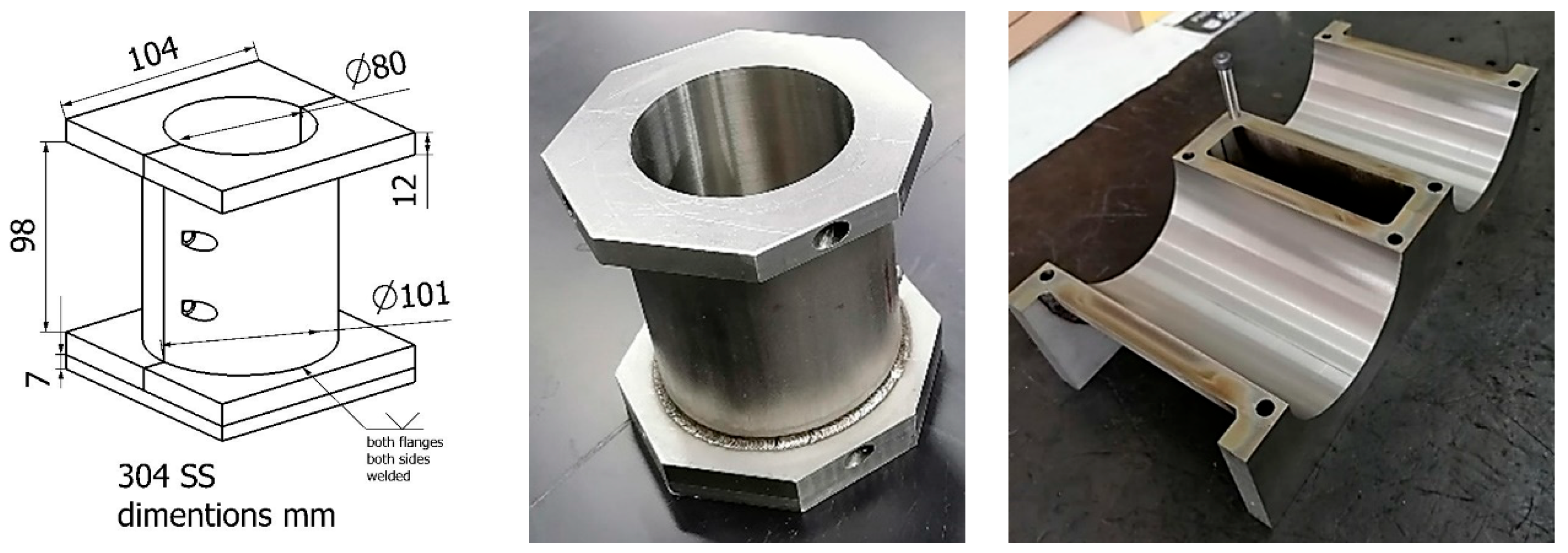
2.1. Raw Materials and Tooling

Barite and calcite were used as thickening and foaming agents to obtain closed-cell A356 foams. Barite is the mineralogical name for barium sulfate, obtained from primary Mexican ore production, which was successfully used in the production of closed-cell aluminum foams [15]. In addition, barite is used as an aggregate in “heavy” cement, as a filler or extender, or as a weighting agent in petroleum well-drilling mud specification. A detailed characterization of the barite used in the production of aluminum alloy foams was previously reported [15]. The grain refinement and modification of the aluminum alloy A356 was carried out by adding the commercial Al-5Ti-1B and Al-10Sr master alloys supplied by KBM—Affilips. The calcite and barite were obtained by the suppliers Fermont and Representaciones técnicas S.A. de C.V., respectively. The master alloys were drilled to obtain burr. Table 1 shows the composition, mean size, and purity of the raw materials used for the production of refined and modified A356 foams.
For the manufacture of the metallic foams, a bipartite stainless steel mold was designed to allow the foaming and refining-modification processes of the alloy to be carried out in the liquid state; in addition, the mold allowed adequate solidification and subsequent extraction of the foam. Figure 1 shows various stages of the design of the bipartite metal mold.

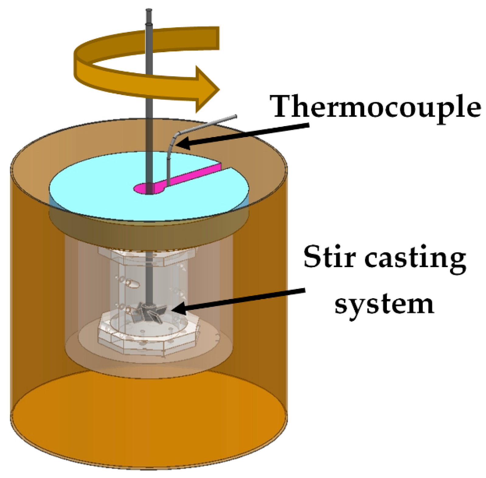
2.2. Fabrication of A356 Aluminum Alloy Foams

Ingots of the aluminum alloy A356 were acquired from a local supplier with the chemical composition shown in Table 2.
Figure 2 shows the experimental system used to produce A356 metallic foams. An electrical furnace containing the bipartite mold is shown. The heating system was an electrical furnace enabled with control of temperature to within ±3 °C of the set values. The scheme also shows a stir casting system and the temperature was measured with a K-type thermocouple.
Four A356 metallic foams were produced using barite and calcium carbonate as thickening and foaming agents, respectively. Before the foaming procedure, a melt treatment was carried out to refine and modify the melt by adding Al-5Ti-1B and Al-10Sr master alloys, respectively. Foams 1 and 2 were produced without the refining and modifying melt treatment while foams 3 and 4 were made with the melt treatment of refining and modifying before the foaming procedure. The experimental procedure is as follows:
(1) Modifying and refining the melt (melt treatment). 350 g of the master alloy was set in a bipartite stainless steel mold (80 mm in diameter and 122 mm in height). The alloy A356 was melted at 680 °C and a 0.05% of the mass charge of the Al-10Sr master alloy was added for the modification of the alloy. Then, the refining was carried out by adding 0.05% of the mass charge of the Al-5Ti-1B master alloy. Both treatments were carried out at 680 °C and a constant stirring speed of 600 rpm for 5 min, after which the molten was allowed to settle for 7 min for each treatment to obtain an adequate distribution and reaction of the master alloys used.
(2) Foaming procedure. After the modifying and refining treatments, the temperature of the metal bath was increased to 715 °C. The foaming trials were carried out using a stir-caster system with a stainless steel paddle axle. The viscosity of the melt was modified by adding 1 wt% of the mass charge of BaSO4 at a constant stirring speed of 600 rpm for 1 min, then stirring was increased to 1200 rpm and maintained for 2 min, and then the stirring speed was increased to 1500 rpm and maintained for 3 min. This procedure increased the viscosity of the alloy. Afterward, 1 wt% of CaCO3 of the mass charge was added as a foaming agent into the melt at a stirring speed of 1500 rpm for 45 s. After the addition of the foaming agent, the melt was kept in the furnace at the holding temperature of 700 °C for 2 min to allow the releasing of CO2 and, hence, the foam formation. The cooling procedure was carried out as soon as the expansion process took place. The mold containing the melt was removed from the furnace and cooled by forced convection by an air flow generated by a turbo blower.

2.3. Foam Characterization

Four A356 closed-cell foams were manufactured by the experimental procedure reported by adding BaSO4 and CaCO3 as thickening and foaming agents, respectively. Foams 3 and 4 were produced with the refining and modifying treatments while foams 1 and 2 were produced without any melt treatment. The fabricated A356 aluminum foams were cut on the cross-section to obtain samples to evaluate density, cell structure, and compression resistance. At least 5 cubic samples of 30 mm each side were obtained from each metallic foam produced for compression tests and porosity determination. Figure 3 shows the foam regions where the cubic samples were extracted.
Densities of the foams were deduced from the weights and volumes of the cubic samples and the relative density was defined by the ratio ρ/ρs, where ρ and ρs correspond to the foam and solid densities, respectively. The porosity (%) was obtained using Equation (1).
Pr % = 1 ρ f o a m ρ A 356 a l l o y × 100
where Pr is the porosity, ρfoam is the foam density, and ρA356 alloy = 2.56 g cm−3. The cell structure was observed and analyzed by optical microscopy and the image analyzer Carnoy.
The microstructural characterization was carried out by obtaining optical micrographs with an inverted metallurgical microscope Olympus PMG-3 of at least 6 different foam regions closer to the extraction zone of the cubic samples as can be observed in the red rectangles of Figure 3. The cell size was measured by the linear intercept method and the basic shape parameters of Carnoy software. Images in the range of 60 to 130 cells were obtained and analyzed for each foam while at least 30 measurements of the length of the dendrites over 6 different regions of each metallic foam chosen randomly were analyzed. Before taking measurements, the software was calibrated to obtain images from pixels to microns.
Because cast aluminum alloys feature dendritic primary structures, the secondary dendritic arm spacing was determined to provide evidence of the effect of the melt treatments. The secondary dendritic arm spacing (SDAS) was calculated using Equation (2) and the measurements of the dendrite’s features.
S D A S = L N 1
where N represents the number of secondary arms counted only along 1 side of the primary arm, and L is measured as the length parallel to the primary arm that only extends from center to center of the counted secondary arms according to method D [27], which considers that the dendrite asymmetry does not influence the measurement procedure [28,29,30]. Figure 4a shows a dendrite scheme for the SDAS parameters considered in Equation (2) while Figure 4b shows a length dendrite measurement with the software Carnoy and the number of secondary arms in the dendrite. The red bar represents the length of the dendrite. The average values of the measurements were reported.
Cubic compression samples of 30 mm each side were obtained from each metallic foam as is observed in Figure 3. Uniaxial compression tests at room temperature were performed using a universal testing machine (Shimadzu 100 kN/10 ft capacity). All tests were applied under displacement control with a constant cross-head speed of 0.5 mm min−1 (with a strain rate of 2 × 10⁻² s−1). The stress–strain data were deduced from the recorded load-displacement data, which were recorded using a data acquisition unit and a computer. The stress–strain data were reported in terms of engineering stress and strain. The mechanical parameters of metal foams were determined using the standard method for the compression of porous metals (ISO 13314:2011).

3. Results

Figure 5 shows optical micrographs of the A356 aluminum alloy to different magnifications. The microstructure consists of an aluminum-rich dendritic matrix (α-Al phase) and a eutectic microstructure formed by coarse silicon particles distributed in a plate-like morphology.

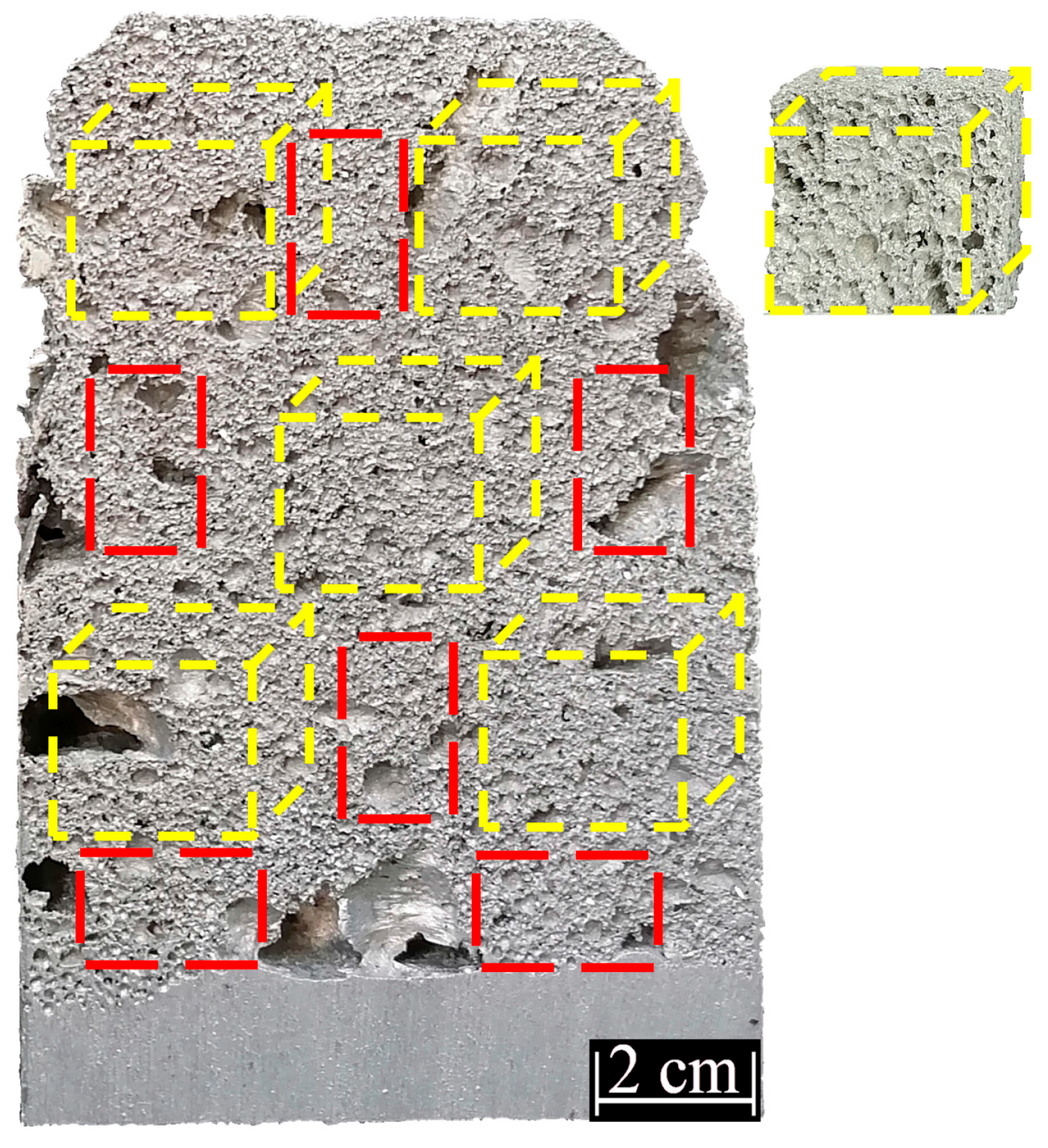
3.1. Structure Properties of the A356 Aluminum Alloys Foams

Figure 6a–d shows representative A356 aluminum alloy foams produced with the additions of barite (BaSO4) and calcite (CaCO3) as thickening and foaming agents, respectively. The foams of Figure 6c,d were obtained together with the modified and refined treatments of the melt while foams 6a,b were obtained without the melt treatment. A good response in the formation of the A356 alloy foams under the proposed experimental conditions is shown. The expansion of the foams was almost the same, reaching a height of around 16 cm except for foam 1, which had a lower expansion due to a drainage problem during the cooling stage. Two foams show a big bubble located at the bottom of the foam due to vortices formed by the agitation of the liquid metal. In general, the foams produced showed a higher homogeneity in their metallic structure.
Table 3 summarizes the average results of density, relative density, and porosity for the foams obtained with and without the melt treatment.
The percentage of porosity Pr (%) of the foams was calculated using Equation (1). It is observed that the porosity is slightly higher for the foams refined and modified. The relative density of the foams was similar; however, foam 1 obtained a higher relative density due to its lowest expansion. The porosity and relative density differences between both experimental conditions are minimal. The highest Pr (%) was obtained for foam 4 that was produced with the refining and modifying treatments.
The cell size distribution of the foams produced is shown in Figure 7. The results are the average of at least 6 measurements in different regions of the foams, as can be observed in the foam of Figure 3. It is observed that the scattered column sets illustrate a scattered cell size distribution, indicating the foam pores are heterogeneous. According to Figure 7, the pores in foams 3 and 4 with the narrowest column sets are more uniformly distributed for smaller cell sizes than those in other foams.
In addition to their lowest relative density, foams 3 and 4 also presented the smallest pore sizes. Thus these foams have the most uniform pores.
Figure 8a–d show representative cell structures of the A356 aluminum alloy foams manufactured with and without the melt treatment in regions located closer to the center of the foams. It is observed that the foam cells are essentially spherical and partially closed. The foams produced without the melt treatments showed the largest pore size in the range of 0.3 to 2.4 mm. On the other hand, the foams manufactured by adding refining and modifying agents showed the smallest pore sizes in the range of 0.2 to 1.6 mm.
Figure 9 shows the foam microstructures obtained using optical microscopy to different magnifications for foams 1 and 3, refined and modified and without the melt treatment, respectively.
The A356 alloy foams produced without the melt treatment show that the silicon crystals in the eutectic mixture grow in a faceted manner. The metallographic sections analyzed show that the silicon crystals develop ahead of the aluminum phase, showing a morphology-like fan-shaped structure characterized by an Al-rich dendritic matrix (α-Al phase) and a eutectic mixture (Al-Si). This type of eutectic structure gives rather poor mechanical properties to the material, obtaining a brittle behavior. The modification could alter the growth of the eutectic silicon to produce an irregular fibrous form rather than the usual acicular structure [31]. The addition of 0.05% of the Al-10%Sr master alloy during the foaming process leads to obtaining globular and semifibrous crystals of the eutectic silicon. It is observed from Figure 9c,d that coarse and elongated silicon particles were partially globulized by the modifier added, as shown in Figure 9g,h. Additionally, the addition of 0.05% of the grain refiner Al-5Ti-1B master alloy promotes the concentration of effective grain nucleation sites by effective heterogeneous nucleation. Thus, both the grain size and SDAS tend to decrease. To quantitatively characterize the grain refinement effect, the SDAS of the A356 foams produced was determined.

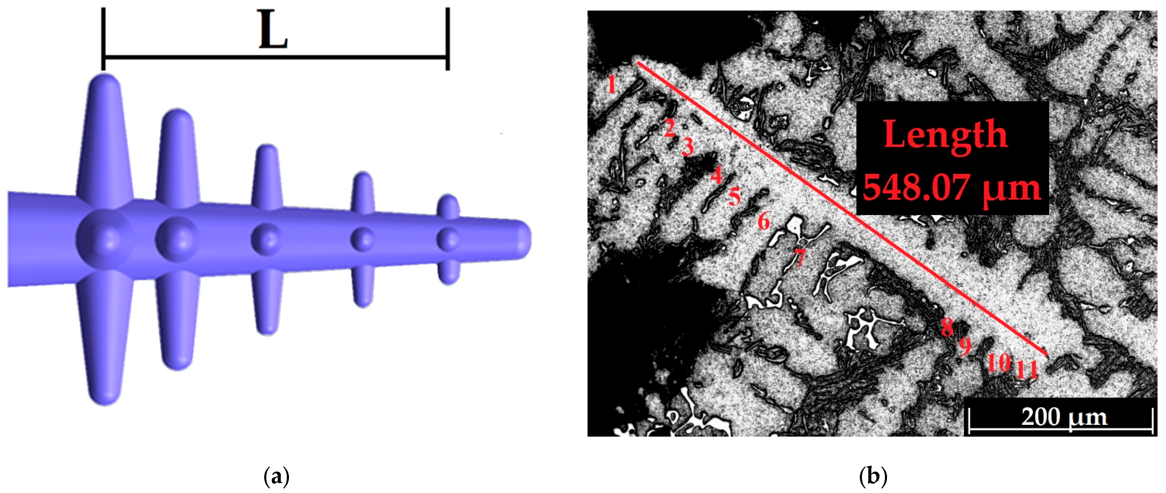
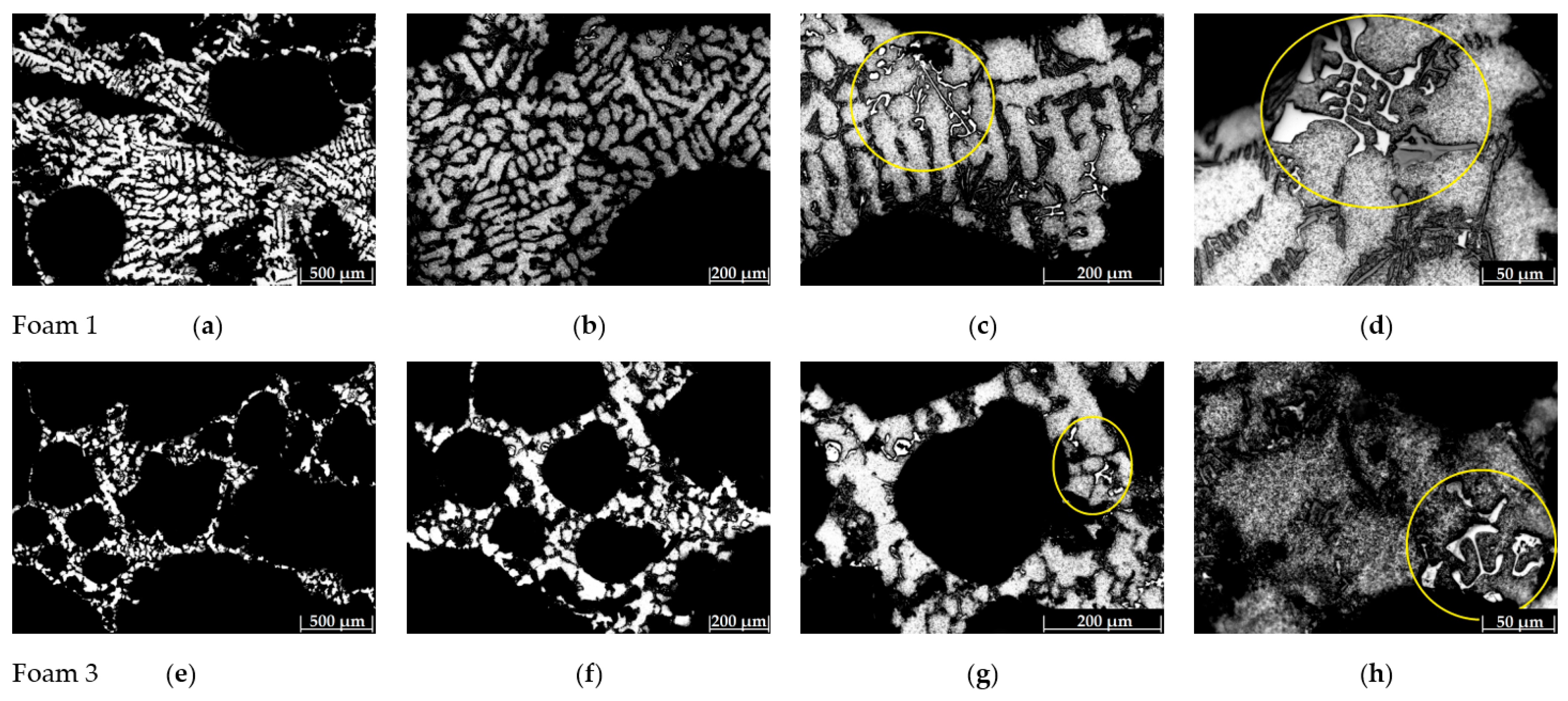
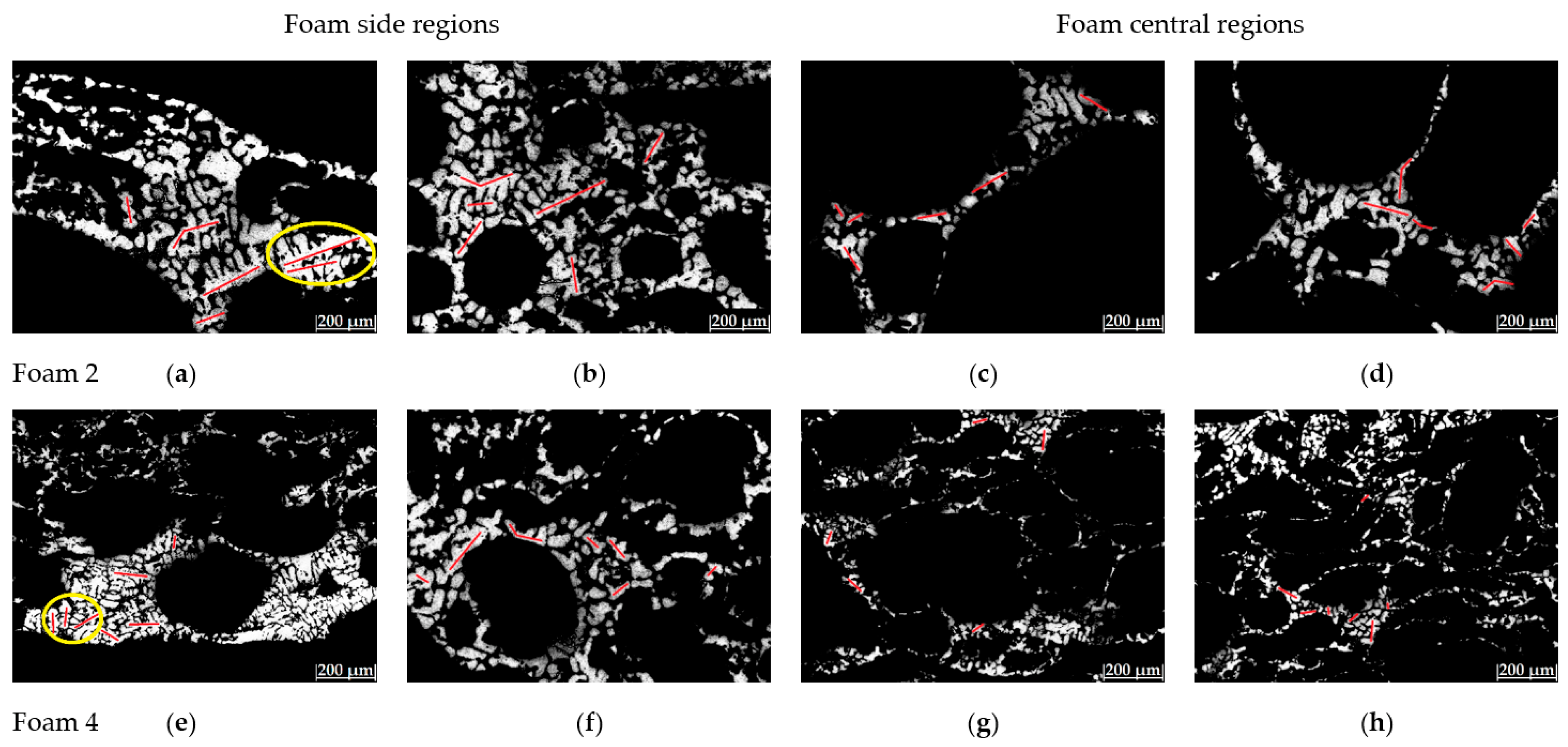
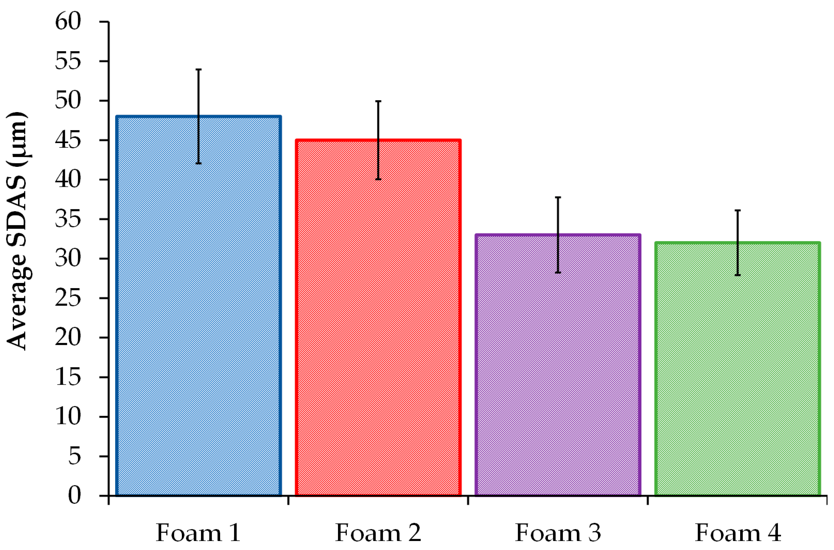
3.2. SDAS Determination

Figure 10 shows the SDAS measurement for the cell walls of the A356 aluminum alloy foams 2 and 4 produced without and with the melt treatment, respectively, in regions located closer to the mold wall and the center of the foams. Different measurements of the dendrite length were carried out, some of which are observed by the red bar on the micrographs in Figure 10.
It is evident from Figure 10e that foam 4 shows a dendrite size smaller than foam 2 (Figure 10a). The addition of the grain refiner Al-5Ti-1B master alloy to foam 4 led to a decrease in both the dendrite length and SDAS. In general, the foams produced with and without the melt treatment showed a significant refinement in the dendritic structure located closer to the mold wall relative to regions closer to the center of the foams. This behavior is due to a faster rate of foam cooling where the dendritic nucleation rate increases, which aids in the formation of a great number of smaller dendrites [32]. On the other hand, the effect of the addition of the grain refiner is observed by a decrease in the grain size and SDAS in foams 3 and 4. The α-Al grain size is known to strongly depend on the potent nucleation sites and undercooling. The previous reports revealed that strontium can hardly induce grain refinement [33,34]. Figure 11 shows the average SDAS determination by using Equation (2), the dendrite length measurements, and the number of secondary arms for the A356 aluminum foams produced.
It is shown that the lowest average SDAS values were obtained for the foams produced with the addition of the grain refiner. The size of the dendritic microstructures of the foams produced indicated by the SDAS determination is mainly influenced by (1) the grain refiner added to the melt and (2) the cooling rate of the solidification process.
In the first case, the addition of the Al-5Ti-1B master alloy to the melt increases the number of nuclei present in the liquid metal for grain growth as it begins to solidify. Titanium, particularly associated with boron, has a powerful nucleation effect. The grain refinement in addition to a faster cooling rate promotes a smaller grain size and SDAS.
In the second case, the solidification time of the foams produced and cooled by a fast-blowing air flow was estimated at 300 s (1.93 K/s). It was reported [35,36] that the solidification rate in the middle region of foams during solidification by using slow-blowing air and fast-blowing air was 0.7 ± 0.2 and 1.7 ± 0.5 K/s, respectively. The solidification time estimated in the foams produced matches the solidification rate reported in [35,36]. Much higher cooling rates are expected in regions closer to the mold wall. It is generally recognized that the effective thermal conductivity of foam materials is closely related to the relative density and the cell wall thermal conductivity [37,38,39]. In addition, the increase of the cell size inhomogeneity and cell shape irregularity could improve the thermal insulation performance of closed-cell foam materials [40], which allow obtaining a slower cooling rate in the central region of the foams, thus increasing the SDAS. It is widely accepted that many mechanical properties are related to the SDAS, whereas the best properties are always associated with the smallest SDAS [25,26,41].

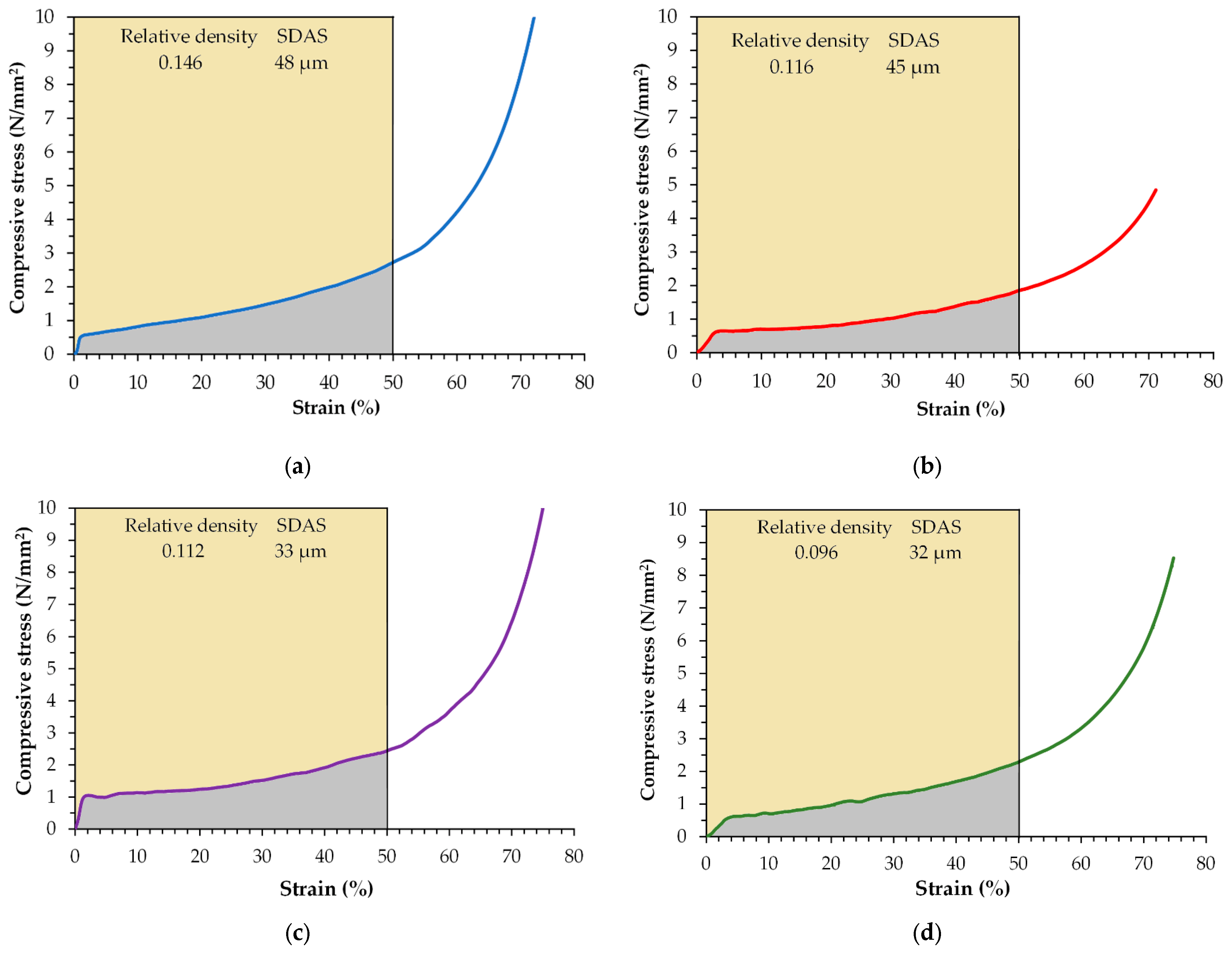
3.3. Compressive Behavior

Figure 12 shows the stress-strain compression curves for A356 aluminum alloy foams manufactured with and without the melt treatment. Typical stress-strain curves of closed-cell metallic foams were obtained, which involve three distinct regimes under compressive loading. The curves display an initial linear elastic region, where stress increased at a very low rate; followed by a plastic plateau stage, where the stress increased slowly as the strain proceeded due to the plastic deformation of the cell struts; then, a densification stage registered at 50% strain, where stress increased significantly with a slight increase of the strain due to the densification of the collapsed cells. In all cases, the foam compression curves obtained are smooth, without the presence of oscillations or serrations in the plateau regions.
The experimental mechanical properties obtained from the compressive stress-strain curves are summarized in Table 4.
The results show that all mechanical parameters, yield stress (σ°), plateau stress (σpl), and the energy-absorption capacity increase when the relative density increases and the pore size decreases. Foam 1 exhibits the highest energy-absorption capacity because it presents the highest relative density with the lowest porosity; thus, the cell-strut thickness, as well as the strength of the foam, increase. However, the remaining foams show a similar relative density and then the SDAS is the main parameter involved in the strength of the foams. Therefore, the highest mechanical properties were obtained for the closed-cell A356 aluminum foams with the lowest SDAS. It was reported that foams containing smaller pores produced with high cooling rates have high yield strength and high energy-absorption capacity [42]. In addition, it is also well known that the production of metal foams by adding a foaming agent requires stabilizing particles; in this sense, the TiB2 and TiC refiners are suitable foam stabilizing additives for aluminum alloys, increasing both the foam porosity and the mechanical properties [43]. Significant improvements in the mechanical properties have been obtained by a combination of grain refinement and modification to an extent that was not possible by either of them alone [44,45]. The benefits of carrying out both treatments are a significant improvement in the mechanical properties of the alloy [45,46], which were also reflected in the foam’s properties. High-strength cell walls make up the high-strength foam. The refining treatment allows for obtaining a small and finer dendritic structure, while the modifier added caused the formation of a fine irregular fibrous form of silicon. Thus the compressive behavior increased. Increasing the solidification rate also influences the response of the cellular structure, decreasing the SDAS; therefore, the global performance of the foam (matrix and structure) is improved.

4. Conclusions

1.
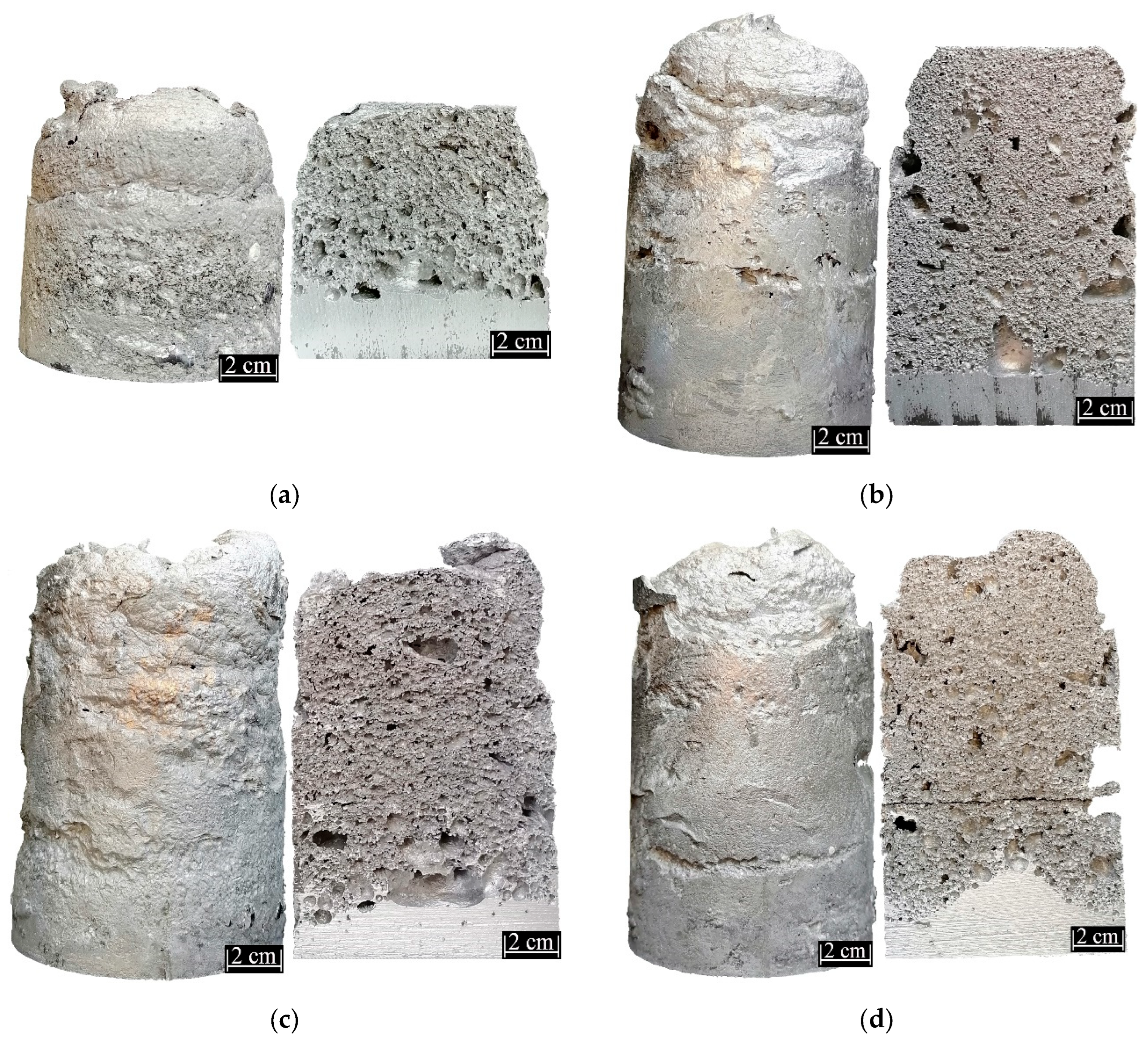
A melt route process was established to obtain closed-cell A356 aluminum alloy foams refined and modified using 0.05% of Al-5Ti-1B and Al-10Sr of the mass charge, respectively, to 700 °C.
2.
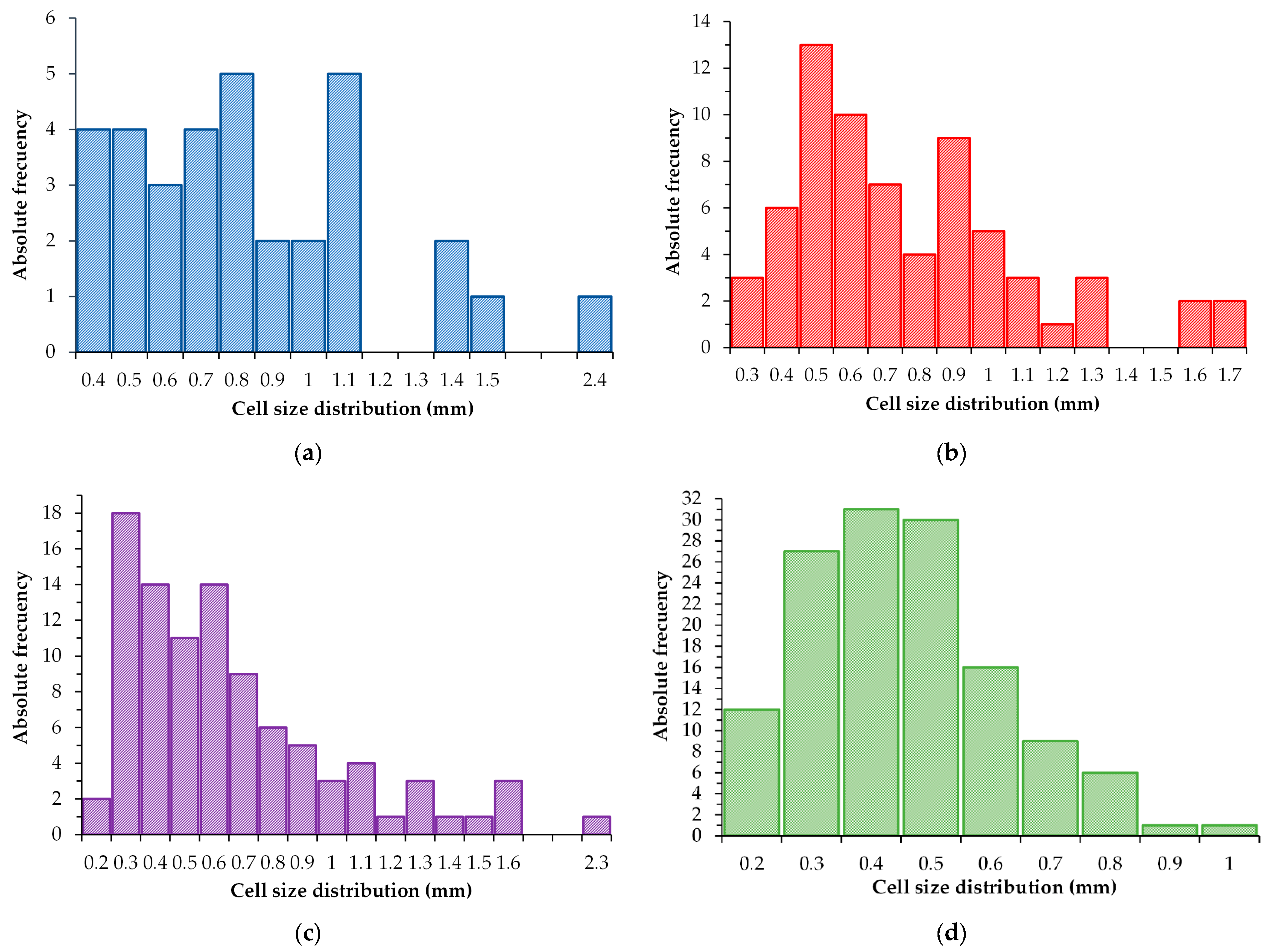
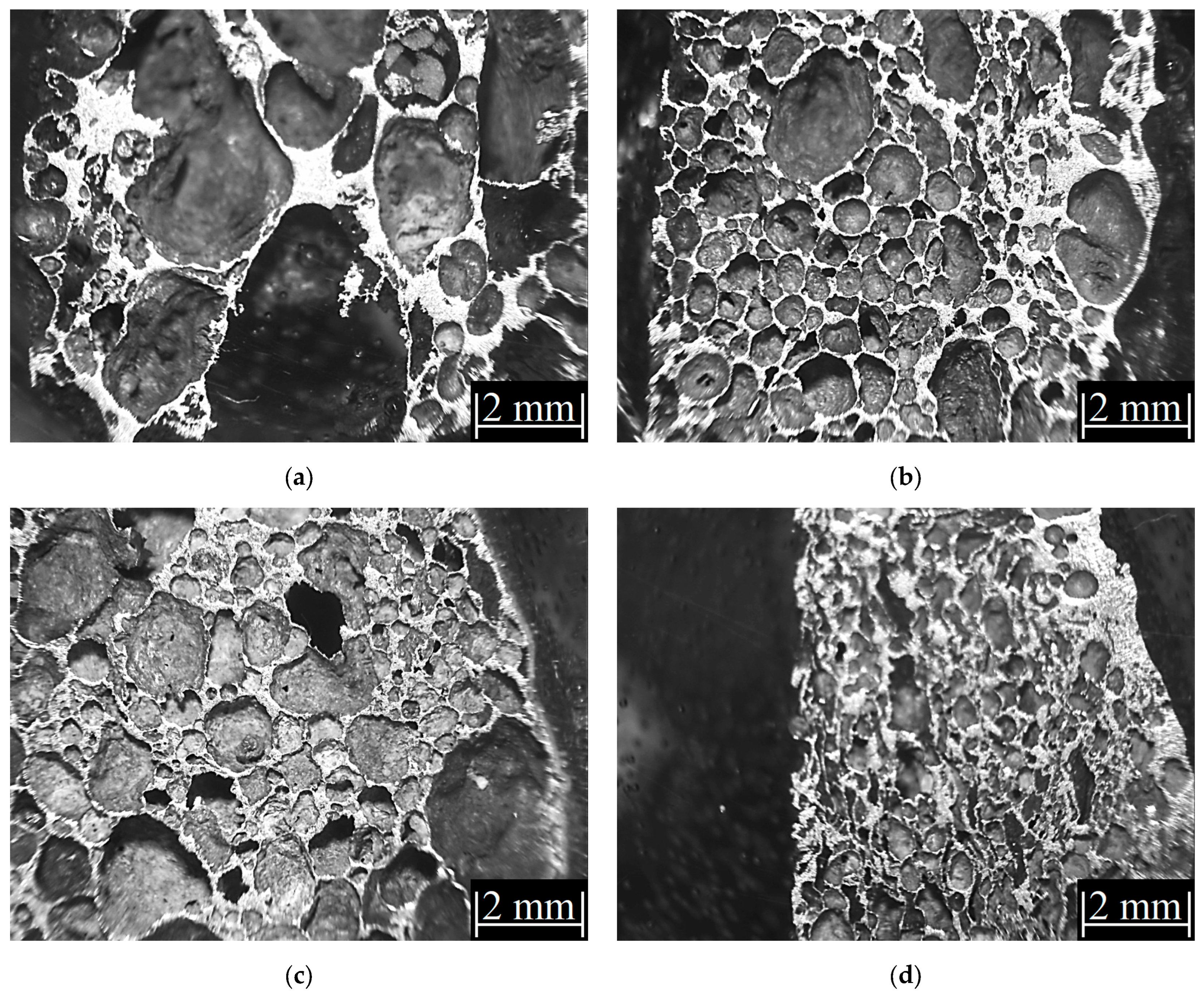
A uniform-size cell distribution with the lowest relative density and the highest porosity was obtained for the refined and modified A356 aluminum alloy foams.
3.
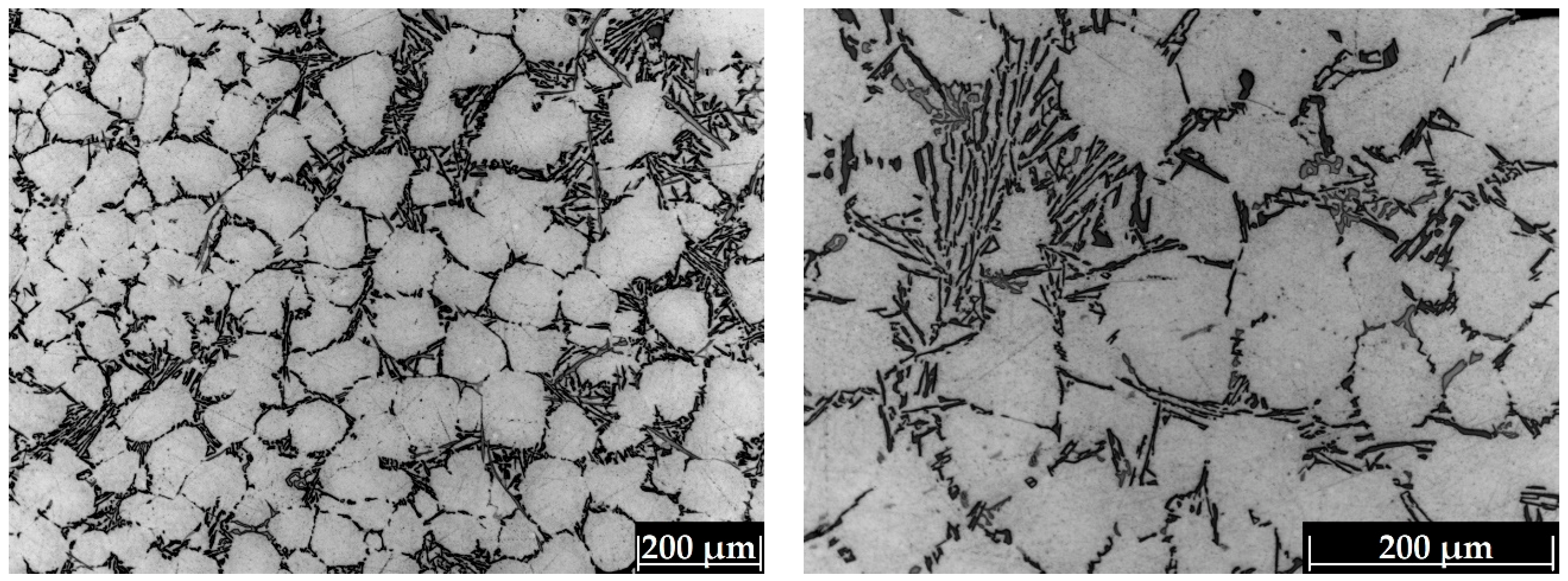
The high solidification rate imposed during the cooling step allows obtaining lower SDAS values in foam regions closer to the mold walls; furthermore, the lowest SDAS values were obtained in the refined foams where the Al-5Ti-1B master alloy effectively refined the grain size of the A356 aluminum alloy foam while the addition of the Al-10Sr master alloy caused the formation of solid solution dendrites and a fine irregular fibrous form of silicon rather than the usual acicular structure.
4.
The modification and refinement of the cell wall is a feasible way to improve foam performance, as was pointed out by the compression tests where the highest energy-absorption capacity was obtained for the foams with the lowest SDAS.

Author Contributions

Conceptualization, A.C.R.; Data curation, J.A.R.S.; Formal analysis, Eduardo Colin García; Investigation, A.J.P.M., E.C.G., R.G.S.A. and M.Á.S.R.; Methodology, A.J.P.M., A.C.R., R.G.S.A. and M.Á.S.R.; Software, A.J.P.M. and J.A.R.S.; Visualization, E.C.G.; Writing—original draft, A.C.R.; Writing—review & editing, A.C.R. All authors have read and agreed to the published version of the manuscript.

Funding

This research received no external funding.

Data Availability Statement

No additional data.

Acknowledgments

The authors wish to thank the Institutions CONACyT, SNI, COFAA, and SIP-Instituto Politécnico Nacional for their permanent assistance to the Process Metallurgy Group at ESIQIE-Metallurgy and Materials Department.

Conflicts of Interest

The authors declare no conflict of interest.

References

  1. Lee, C.D. Variability in the tensile properties of squeeze-cast Al-Si-Cu-Mg alloy. Mater. Sci. Eng. A 2008, 488, 296–302. [Google Scholar] [CrossRef]
  2. Ejiofor, J.U.; Reddy, R.G. Developments in the processing and properties of particulate Al-Si composites. JOM 1997, 49, 31–37. [Google Scholar] [CrossRef]
  3. Li, R.X.; Li, R.D.; Zhao, Y.H.; He, L.Z.; Li, C.X.; Guan, H.R.; Hu, Z.Q. Age-hardening behavior of cast Al–Si base alloy. Mater. Lett. 2004, 58, 2096–2101. [Google Scholar] [CrossRef]
  4. Jeenager, V.K.; Pancholi, V.; Daniel, B.S.S. The effect of aging on energy absorption capability of closed cell aluminum foam. Adv. Mater. Res. 2012, 585, 327–331. [Google Scholar] [CrossRef]
  5. Ozan, S.; Taskin, M.; Kolukisa, S.; Ozerdem, M.S. Application of ANN in the prediction of the pore concentration of aluminum metal foams manufactured by powder metallurgy methods. Int. J. Adv. Manuf. Technol. 2008, 39, 251–256. [Google Scholar] [CrossRef]
  6. Islam, M.A.; Kader, M.A.; Hazell, P.J.; Brown, A.D.; Saadaftar, M.; Quadir, M.Z.; Escobedo, J.P. Investigation of microstructural and mechanical properties of cell walls of closed-cell aluminium alloy foams. Mater. Sci. Eng. A 2016, 666, 245–256. [Google Scholar] [CrossRef]
  7. Davies, G.J.; Zhen, S. Review metallic foams: Their production, properties and applications. J. Mater. Sci. 1983, 18, 1899–1911. [Google Scholar] [CrossRef]
  8. Dukhan, N. Metal Foams, Fundamentals and Applications, 1st ed.; Destech Publications Inc.: Lancaster, PA, USA, 2013; pp. 1–27. [Google Scholar]
  9. Yuan, W.W.; Chen, X.; Liu, Y.; Li, Y.X. Research on Key Technologies for Batch Preparation of Aluminum Foam Slabs by Melt Foaming Process. Rare Met. Mater. Eng. 2009, 38, 306–310. [Google Scholar]
  10. Miyoshi, T.; Itoh, M.; Akiyama, S.; Kitahara, A. ALPORAS Aluminum Foam: Production Process, Properties, and Applications. Adv. Eng. Mater. 2000, 2, 179–183. [Google Scholar] [CrossRef]
  11. Jin, I.; Kenny, L.D.; Sang, H. Stabilized Metal Foam Body. US Patent No. 5,112,697, 15 August 1992. [Google Scholar]
  12. Akiyama, S.; Ueno, H.; Imagawa, K.; Kitahara, A.; Nagata, S.; Morimoto, K.; Nishikawa, T.; Itoh, M. Foamed metal and method of producing same. US Patent No. 4,713,227, 15 December 1987. [Google Scholar]
  13. Papadopoulos, D.; Omar, H.; Stergioudi, F.; Tsipas, S.; Michailidis, N. A novel method for producing Al-foams and evaluation on their compression behavior. J. Porous Mater. 2010, 17, 773–777. [Google Scholar] [CrossRef]
  14. Banhart, J. Metal foams: Production and stability. Adv. Eng. Mater. 2006, 8, 781–794. [Google Scholar] [CrossRef]
  15. González Nava, M.; Cruz-Ramírez, A.; Suárez Rosales, M.A.; Gutiérrez-Pérez, V.H.; Sánchez-Martinez, A. Fabrication of aluminum alloy foams by using alternative thickening agents via melt route. J. Alloys Compd. 2017, 698, 1009–1017. [Google Scholar] [CrossRef]
  16. Ip, S.W.; Wang, Y.; Toguri, J.M. Aluminum foam stabilization by solid particles. Can. Metall. Q. 1999, 38, 81–92. [Google Scholar] [CrossRef]
  17. Byakova, A.; Kartuzov, I.; Nakamura, T.; Gnyloskurenko, S. The role of foaming agent and processing route in mechanical performance of fabricated aluminum foams. Procedia Mater. Sci. 2014, 4, 109–114. [Google Scholar] [CrossRef] [Green Version]
  18. González-Nava, M.; Cruz-Ramírez, A.; Suárez-Rosales, M.A.; Hernández-Pérez, M.A. Thermodynamic analysis of the aluminum alloy foaming process by melt route. J. Manuf. Process. 2018, 32, 77–84. [Google Scholar] [CrossRef]
  19. Smart, R.F. Metallurgical aspects of Al-Si eutectic piston alloys. Br. Foundrym. 1971, 64, 430–438. [Google Scholar]
  20. Li, P.; Liu, S.; Zhang, L.; Liu, X. Grain refinement of A356 alloy by Al-Ti-B-C master alloy and its effect on mechanical properties. Mater. Des. 2013, 47, 522–528. [Google Scholar] [CrossRef]
  21. Neff, D. Aluminum Casting Technology, 2nd ed.; AFS: Des Plaines, IL, USA, 2001; pp. 28–323. [Google Scholar]
  22. Shabani, M.O.; Mazahery, A.; Bahmani, A.; Davami, P.; Varahram, N. Solidification of A356 Al alloy: Experimental study and modeling. Kov. Mater. 2011, 49, 253–258. [Google Scholar] [CrossRef]
  23. Jha, A.K.; Sreekumar, K. Effect of pores and acicular eutectic silicon particles on the performance of Al–Si–Mg (AS7G03) casting. Eng. Fail. Anal. 2009, 16, 2433–2439. [Google Scholar] [CrossRef]
  24. Flemings, M.; Kattamis, T.Z.; Bardes, B.P. Dendrite arm spacing in aluminium alloys. AFS Trans. 1991, 99, 501–506. [Google Scholar]
  25. Zang, B.; Garro, M.; Tagliano, C. Dendrite arm spacing in aluminium alloy cylinder heads produced by gravity semi-permanent mold. Metall. Sci. Technol. 2003, 21, 3–9. [Google Scholar]
  26. Ananthanarayanan, L.; Gruzleski, J.E. Thermal Analysis Studies on the Effect of Cooling Rate on the Microstructure of the 319 Aluminium Alloy. AFS Trans. 1992, 141, 383–391. [Google Scholar]
  27. Vandersluis, E.; Ravindran, C. Comparison measurement methods for secondary dendrite arm spacing. Metallogr. Microstruct. Anal. 2017, 6, 89–94. [Google Scholar] [CrossRef]
  28. Hanumantha, R.D.; Tagore, G.R.N.; Ranga, J.G. Evolution of artificial neural network (ANN) model for predicting secondary dendritic arm spacing in aluminum alloy casting. J. Braz. Soc. Mech. Sci. Eng. 2010, 32, 276–281. [Google Scholar] [CrossRef] [Green Version]
  29. Zou, Y.; Xu, Z.; Zeng, J. Effect of SDAS on homogenization of Al–Si–Mg casting alloys. Adv. Mater. Res. 2010, 97, 1041–1044. [Google Scholar] [CrossRef]
  30. Easton, M.; Davidson, C.; StJohn, D. Grain morphology of as-cast wrought aluminium alloys. Mater. Trans. 2011, 52, 842–847. [Google Scholar] [CrossRef] [Green Version]
  31. Zhang, X.H.; Su, G.C.; Ju, C.W.; Wang, W.C.; Yan, W.L. Effect of modification treatment on the microstructure and mechanical properties of Al-0.35%Mg-7.0%Si cast alloy. Mater. Des. 2010, 31, 4408–4413. [Google Scholar] [CrossRef]
  32. Askeland, D.; Pradeep, F.; Wendelin, W. The Science and Engineering of Materials, 6th ed.; Cengage Learning, Inc.: Stamford, CT, USA, 2011; pp. 337–341. [Google Scholar]
  33. Xu, C.; Xiao, W.; Hanada, S.; Yamagata, H.; Ma, C. The effect of scandium addition on microstructure and mechanical properties of Al-Si-Mg alloy: A multi-refinement modifier. Mater. Charact. 2018, 110, 160–169. [Google Scholar] [CrossRef]
  34. Qiu, C.; Miao, S.; Li, X.; Xia, X.; Ding, J.; Wang, Y.; Zhao, W. Synergistic effect of Sr and La on the microstructure and mechanical properties of A356.2 alloy. Mater. Des. 2017, 114, 563–571. [Google Scholar] [CrossRef]
  35. Lehmhus, D.; Banhart, J. Properties of heat-treated aluminum foams. Mater. Sci. Eng. A 2003, 349, 98–110. [Google Scholar] [CrossRef]
  36. Lázaro, J.; Solórzano, E.; Rodríguez-Pérez, M.A.; Kennedy, A.R. Effect of solidification rate on pore connectivity of aluminum foams and its consequences on mechanical properties. Mater. Sci. Eng. A 2016, 672, 236–246. [Google Scholar] [CrossRef] [Green Version]
  37. Iasiello, M.; Bianco, N.; Chiu, W.K.S.; Naso, V. Thermal conduction in open-cell metal foams: Anisotropy and Representative Volume Element. Int. J. Therm. Sci. 2019, 137, 399–409. [Google Scholar] [CrossRef]
  38. Kumar, P.; Topin, F. Impact of anisotropy on geometrical and thermal conductivity of metallic foam structures. J. Porous Media 2015, 18, 949–970. [Google Scholar] [CrossRef]
  39. Qiu, L.; Zou, H.; Tang, D.; Wen, D.; Feng, Y.; Zhang, X. Inhomogeneity in pore size appreciably lowering thermal conductivity for porous thermal insulators. Appl. Therm. Eng. 2018, 130, 1004–1011. [Google Scholar] [CrossRef]
  40. Hu, Y.; Fang, Q.Z.; Yu, H.; Hu, Q. Numerical simulation on thermal properties of closed-cell metal foams with different cell size distributions and cell shapes. Mater. Today Commun. 2020, 24, 100968. [Google Scholar] [CrossRef]
  41. Birol, Y. Impact of grain size on mechanical properties of AlSi7Mg0.3 alloy. Mater. Sci. Eng. A 2013, 559, 394–400. [Google Scholar] [CrossRef]
  42. Shi, T.; Chen, X.; Cheng, Y.; Li, Y. Foaming process and properties of 6063 aluminum foams by melt foaming method. Mater. Trans. 2017, 58, 243–248. [Google Scholar] [CrossRef] [Green Version]
  43. Bacsán, N.; Murty, M.; Vinod, G.; García, F.; Banhart, J. New Foam Stabilizing Additive for Aluminium. In Proceedings of the Metfoam 2007, Montreal, QC, Canada, 5–7 September 2007; DES Tech. Publications: Lancaster, PA, USA; pp. 27–30. [Google Scholar]
  44. Kori, S.; Murty, B.; Chakraborty, M. Development of an efficient grain refiner for Al-7Si alloy and its modification with strontium. Mater. Sci. Eng. A 2000, 283, 94–104. [Google Scholar] [CrossRef]
  45. Basavakumar, K.; Mukunda, P.; Chakraborty, M. Influence of grain refinement and modification on microstructure and mechanical properties of Al-7Si and Al-7Si-2.5Cu cast alloys. Mater. Charact. 2008, 59, 283–289. [Google Scholar] [CrossRef]
  46. Samuel, E.; Golbahar, B.; Samuel, A.; Doty, H.; Valtierra, S.; Samuel, F. Effect of grain refiner on the tensile and impact properties of Al-Si-Mg cast alloys. Mater. Des. 2014, 56, 468–479. [Google Scholar] [CrossRef]
Figure 1. Bipartite stainless steel metallic mold.
Metals 13 00622 g001
Figure 2. Experimental system for metallic foam production.
Metals 13 00622 g002
Figure 3. Cross-section view of the structure of the A356 aluminum alloy foam showing sample locations for microstructural characterization and compressive trials.
Metals 13 00622 g003
Figure 4. SDAS determination shows (a) the dendrite scheme for the SDAS measurement, and (b) the length measurement of a dendrite and the number of secondary arms.
Metals 13 00622 g004
Figure 5. Optical microphotographs of the A356 alloy to different magnifications.
Metals 13 00622 g005
Figure 6. Expansion and cross-section view of the structure of the A356 aluminum alloy foams manufactured of (a) Foam 1, (b) Foam 2, (c) Foam 3, and (d) Foam 4.
Metals 13 00622 g006
Figure 7. Cell size distribution of aluminum foams of (a) Foam 1, (b) Foam 2, (c) Foam 3, and (d) Foam 4.
Metals 13 00622 g007
Figure 8. Representative optical microphotographs of the central region of the A356 aluminum alloy foams manufactured of (a) Foam 1, (b) Foam 2, (c) Foam 3, and (d) Foam 4.
Metals 13 00622 g008
Figure 9. Optical microphotographs of A356 aluminum alloy foams manufactured of foam 1 (without melt treatment) and foam 3 (refined and modified). The micrographs were taken to (a,e) 50×, (b,f) 100×, (c,g) 200×, and (d,h) 500×. The circles show the silicon modification.
Metals 13 00622 g009
Figure 10. Optical microphotographs of A356 aluminum alloy foams 2 and 4 for regions located closer to the mold walls and in central regions of the foams. The micrographs were taken to (a,e) 50×, (b,f) 100×, (c,g) 200×, and (d,h) 500×. The circles show some dendrites while the red bar represent the dendrite length.
Metals 13 00622 g010
Figure 11. Variation of the average SDAS determination for the foams produced.
Metals 13 00622 g011
Figure 12. Compressive stress-strain curves of A356 aluminum alloy foams of (a) Foam 1, (b) Foam 2, (c) Foam 3, and (d) Foam 4.
Metals 13 00622 g012
Table 1. Raw materials.
AgentsPurity (%)Particle Size (µm)
Barite (BaSO4)9645
Calcite (CaCO3)98.514
Al-5Ti-1B5Ti, 1B400
Al-10Sr10 Sr400
Table 2. Chemical composition of the A356 aluminum alloy.
Alloywt %
A356SiFeCuMnMgAl
7.320.370.080.160.3891.69
Table 3. Experimental densities and porosity of the A356 alloy foams.
Experimental ConditionFoam SampleDensity
ρ * (g cm−3)
Relative Density
ρ */ ρ A356 alloy
Pr
(%)
Without melt treatment10.3890.14685.4
20.3090.11688.1
With melt treatment30.3150.11288.4
40.2540.09690.4
Table 4. Experimental mechanical properties and energy-absorption capacity of the A356 aluminum alloy foams.
Experimental ConditionFoam Sampleσ0 (N/mm2)Plateau Stress σpl
(N/mm2)
Energy Absorption
W (MJ m−3)
Without melt treatment10.581.490.69
20.631.040.49
With melt treatment31.041.530.74
40.621.300.59
Disclaimer/Publisher’s Note: The statements, opinions and data contained in all publications are solely those of the individual author(s) and contributor(s) and not of MDPI and/or the editor(s). MDPI and/or the editor(s) disclaim responsibility for any injury to people or property resulting from any ideas, methods, instructions or products referred to in the content.

