Article

Characteristics for Gallium-Based Liquid Alloys of Low Melting Temperature

1
College of Resources, Environment and Materials, Guangxi University, Nanning 530004, China
2
Graduate School of Engineering, The University of Tokyo, Tokyo 113-8656, Japan
*
Author to whom correspondence should be addressed.
Metals 2023, 13(3), 615; https://doi.org/10.3390/met13030615
Submission received: 16 February 2023 / Revised: 13 March 2023 / Accepted: 16 March 2023 / Published: 19 March 2023
(This article belongs to the Special Issue Advances in Characterization of Heterogeneous Metals/Alloys)

Abstract

:
Gallium alloys are ideal base carriers for temperature-sensitive ferrofluids, which can be used for energy convection, soft robotics, microchannels, magnetorheological devices, etc. In this study, gallium was mixed with different substances (In, Sn, Zn, Ge, and Al) to obtain a low melting point, reduce the wetness and adhesion of its alloys, and realize low viscosity. The melting point, contact angle on certain solid plates, viscosity, and viscoelasticity of the gallium alloys were measured, and some useful gallium alloys were obtained. The experimental results showed that Ga80In10Sn10 had lower wettability at a larger contact angle of 148.6° on the Teflon plate. Here, (Ga80In10Sn10)97Zn3 with a melting point of 8.2 °C, lower than the melting point of Galinstan, was developed. It had a viscosity about three times that of water at room temperature and an elastic response from 0.1 to 100 Hz at a 1% strain amplitude for the viscoelasticity. It was expected that a kind of temperature-sensitive magnetic fluid with a gallium-based liquid alloy as the base carrier liquid would be prepared in the future with Teflon as the container to achieve energy conversion under the drive of the magnetic field.

Graphical Abstract

1. Introduction

Gallium alloy has been studied for making lead-free solders [1]. However, here, the low melting temperature of the gallium alloy was studied for processing, chemistry, and function [2]. More specifically, gallium alloys are ideal base carriers for temperature-sensitive ferrofluid (magnetic fluid) and energy convection. They can also be used in various fields such as “soft robotics [3], microchannel [4], magnetorheological fluid [5], 3D printing [6], catalysis, energy storage [7], chemical sensors [8], etc.” Our group studied gallium-based ferrofluid [9]. Temperature-sensitive ferrofluid is very suitable as a medium for energy transportation and energy conversion and has important application prospects in the heat dissipation components of electronic products such as computers and cell phones [10,11], and can also be applied to ferrofluid temperature difference power generation, ferrofluid temperature difference drives, magnetic refrigeration, magnetic heating, magnetic thermal medicine, and other fields [12]. Currently, most temperature-sensing ferrofluids are based on oil or water. However, problems exist, such as high viscosity, low thermal conductivity, and small magnetic variation with temperature changes [13]. The liquid metal gallium and its liquid alloy are ideal for thermosensitive ferrofluid carrier liquids [14]. Gallium (density 5.91 g/cm3, thermal conductivity 40.6 W·m−1 k−1) has a melting point of 29.8 °C. Therefore, it has the advantage of remaining liquid when used at room temperature. It has been reported that when silicon nanoparticles are dispersed in metal gallium with a melting point of 30 °C, they remain liquid even at 0 °C due to the super-cooling effect [15]. Some gallium alloys can remain liquid at room temperature, with good electrical and thermal conductivity properties. Additionally, though the ferrofluid dispersing micron size Gd powder (0.2–2.3 wt.%) in Galinstan was reported to use magnetocaloric liquid, the oxidation prevention of particles and the liquid and higher dispersion of particles was expected [16]. Here, the characteristics of metal liquid as a base carrier of ferrofluid that did not disperse magnetic particles will be investigated.
Gallium alloy is a eutectic alloy with very low viscosity, high surface tension as a “liquid”, and very high tensile thermal conductivity and electrical conductivity as a “metal” [17]. Gallium has excellent properties and a low melting point, which are the focus of our research. Gallium is commonly mentioned as α-gallium, i.e., an orthogonal system in which each atom harmonizes with seven neighboring atoms to form a highly an-isotropic atomic (Figure 1, made by VESTA 4.6.0). However, the fact is that gallium has many sub-stable phases and a lower melting point. For example, mono-clinic β-gallium has a melting point of −16.3 °C, orthorhombic γ-gallium has a melting point of −35.6 °C, and rhombohedral δ-gallium has a melting point of −19.4 °C [18]. Furthermore, gallium has different phase structures at high pressure, such as Ga-II and Ga-III [19]. This undoubtedly shows the complexity of the gallium phase structure. However, there is still a lack of knowledge about gallium and its liquid phase structure, and more basic research is still needed to follow this up. It also provides an idea to lower its melting point and vigorously trap or stabilize the sub-stable phase. These intrinsic characteristics result in a low melting point, allowing gallium to behave in both covalent and metal bonding in the solid state. When gallium and other metals are mixed at the atomic level, a greater distance between the atoms constitutes a significant structural anisotropy. This indicates that the binding is weak and promotes the rupture of the crystal structure at low temperatures, leading to eutectic (a lower melting point) [17]. Here we have collected melting points of Ga-based alloys from some literatures, as shown in Table 1.
Gallium and its alloys have the lowest melting points, about 10 °C. Galinstan exhibits a low melting point from 11 °C to 13 °C [8,21]. However, it has high wetness (small contact angle) and adhesion. The solidification (freezing) point of Galinstan is −19 °C. Ga, In, and Sn alloys containing Zn, Gd, Bi, and Al have a low melting point. Here, the synthesis of alloys with lower melting points has been investigated. However, they have high wetness and adhesion [28,29] and make it difficult to maintain contact with glass or metal [30]. Therefore, measuring the contact angle of liquid alloys on the plate of glass, copper, aluminum, and plastics is necessary. Additionally, it is required for the Ga alloy to show lower viscosity and to investigate viscoelasticity for it to be utilized in movement applications such as in ferrofluids. Room-temperature gallium-based liquid metals have been widely used in lubrication, sealing, battery, medical, liquid robotics, and many other fields, which can significantly improve product and technical performance [31,32,33,34,35,36,37,38].
In this study, different gallium-based alloys with In, Sn, Zn, and Al were prepared, and the melting point, wetness, and fluidity of gallium alloys were investigated. The purpose was to obtain a liquid alloy with a low melting point and suitable properties that can be used as a temperature-sensitive ferrofluid base carrier.

2. Experiment

2.1. Preparation of Gallium Alloy

Pure Ga(6N) produced by Dowa electronics materials Co., Ltd., Nisaki, Hyogo, Japan was utilized. Metal In, Sn, Zn, and Al were purchased from Lijia metal material Co., Ltd., Xintai, Hebei, China. All the raw materials were stored in an argon-filled glove box. First, the preparation of the type and ratio (weight percentage) for alloying elements was performed in the glove box after the oxidized skin of the raw metal was removed with sandpaper. Next, the prepared alloys were placed in a sample bag filled with alcohol and set in an ultrasonic cleaner for 10 min to wash. After that, the sample was dried and put into the glove box, which was weighed strictly on a balanced scale. Ga was first heated to transform it into a molten state before being added to In, Sn, and other solid metals. The sample was mixed, cooled, and stored in a test tube under a seal. The test tube was removed and put in the ultrasonic cleaner at 40 °C for 1 h. The sample was uniformly melted, and the gallium liquid alloy sample was finally prepared.

2.2. Melting Point Measurement

The melting point of gallium-based liquid metals was measured by differential scanning calorimetry (DSC, NETZSCH DSC 200 F3, NETZSCH, Bavaria, Germany). First, to eliminate the thermal history, the initial temperature was set at 40 °C and held for 1 min. Then, the temperature was lowered to −50 °C at a rate of 5 °C/min, held for 1 min, and then raised to 40 °C at a rate of 5 °C/min to complete the test of the melting point of gallium-based liquid metal.

2.3. Contact Angle Measurement

The flat plates of Teflon (PTFE (polytetrafluoroethylene)), Cu, SiO2, and Al were purchased from the Chunshi new material Co. LTD. Dongguan, Guangdong, China. As the contact angle affected the plate roughness, the plate’s average roughness (nm) was measured using an atomic force microscope (AFM, 5100N, HITACHI, Tokyo, Japan).
The contact angle is a quantitative measure of the surface’s wettability, represented by the angle at which a liquid or vapor interface interacts with a solid surface. The wetting ability was determined using a contact angle measuring instrument (SINDIN SDC-200S, Dongguan, Guangdong, China). A small amount of the gallium-based liquid alloy was extracted with a syringe, a drop of the sample was placed on the substrate, and a screenshot was taken for contact angle measurement. The gallium-based alloys have high wetness and adhesion, and it is difficult to maintain contact with glass or metal. Therefore, it is necessary to explore their contact surfaces. In this experiment, the test platform was at a constant temperature of 20 °C and in an air atmosphere for practical utilization. Gallium-based alloys were put on four different plate substrates of Al, Cu, silica (SiO2), and polymer Teflon to observe the contact angle.

2.4. Viscosity Measurement

Due to the low melting point, low kinematic viscosity, stable properties, and easy corrosion with other metals, many viscosity testing methods were unsuitable for the room temperature viscosity measurement of gallium-based alloys. As the viscosity by the capillary method was affected by adhesion [39], here, the parallel disc type viscometer (HR 20, TA instrument, New Castle, DE, USA) was mainly used, as shown in Figure 2.
In addition, these viscoelastic tests were carried out for the samples using a stress-controlled rheometer [40] (HR 20-TA instrument) with parallel plates, as shown in Figure 2. However, the peculiarities of liquid metals made the experiment difficult because the formation of oxide skins on the liquid metal prevented the uniform metal from filling the gap between the two plates. As a result, the gallium-based alloys were prone to extensive slippage. This was improved by applying a Teflon coating on the surface of the parallel plates.
γ = R × Ω h , σ = 2 M π R 3
γ—shear rate; Ω—rotational angular velocity; σ—shear stress; M—torque

3. Results and Discussion

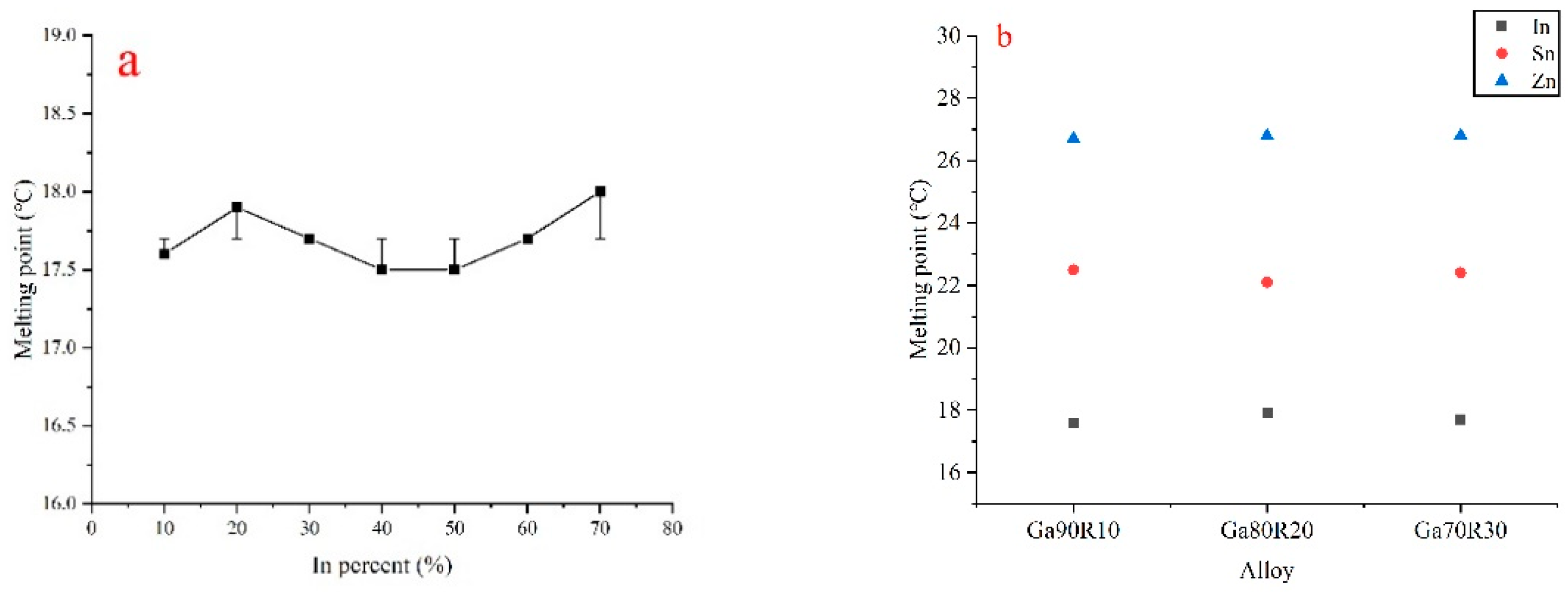
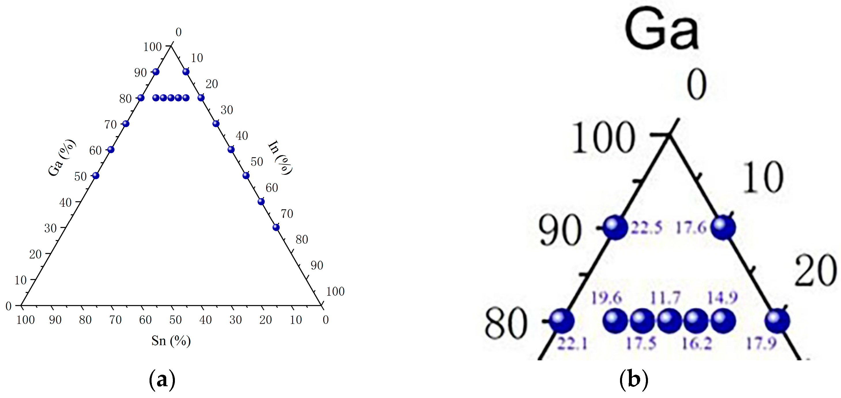
3.1. Melting Point Measurement

The DSC test curve of the alloy (Ga80In10Sn10)97Zn3 is shown in Figure 3. The melting point of (Ga80In10Sn10)97Zn3 was 8.2 °C, and the solidifying point was −29.2 °C. The melting point of gallium-based alloys was successfully reduced by adding In and Sn, compared with pure Ga. By using this method, various kinds of metal alloy melting points were measured. The melting points of the gallium-based alloy are listed in Table 2. Table 2 shows the melting points of other GaIn alloys, as shown in Figure 4a. In the GaIn alloy, the melting point was low, between 17.5 and 18.0 °C, with 10 to 70% In contents in Ga. The melting points of GaSn and GaZn with the GaIn alloy are shown in Figure 4b. The GaSn alloy’s melting point was a little higher, between 22.1 and 22.5 °C with 10 to 50% of Sn in Ga. In the GaZn alloy, the melting point was high, between 26.7 and 26.8, with 10 to 30% of Zn in Ga. The influence of reducing the melting point of the Gallium alloy was that the In effect was larger than Sn and Zn.
The melting points of the same components were relatively close, as shown in Figure 5a. The melting point of the Ga-In-Sn ternary alloy was lower than that of binary alloys. The melting points in the three phases of the GaInSn alloy, including 80% Ga, are shown in Figure 5. The ternary alloy’s different contents greatly influenced the melting point, which differed from the binary alloys. In the examined GaInSn alloy, except for Galinstan, the gallium-based alloy with the lowest melting point obtained was Ga80In10Sn10, which had a melting point of 11.7 °C. The quaternary alloy was explored on the base of Ga80In10Sn10. Small amounts of Al, Ge, and Zn were added to obtain lower melting point alloys (Ga80In10Sn10)97Al3 9.9 °C, (Ga80In10Sn10)97Ge3 10.1 °C, and (Ga80In10Sn10)97Zn3 8.2 °C. In the periodic table, Al, Zn, and Ge are neighboring elements of Ga. Adding the small amount of those elements decreased the melting point, and the density increased to 6.79 g/cm3 for (Ga80In10Sn10)97Zn3. The Ga atom distance measurement in the liquid alloy would be necessary using the X-ray adsorption fine structure analysis (EXAFS) [15] to investigate the Ga-based liquid alloy’s melting point and density changes.
Alloy composition was an important factor affecting the melting point, which was generally lower than the corresponding pure metal. Because the size of the atoms in the alloy was different and their arrangement was not as regular as that of the pure metal, the bonds between the atoms were weaker and reduced the melting temperature. Adding elements such as In, Sn, and Zn changed the atomic arrangement structure of Ga. The metal bonds weakened as the Ga atom connected seven anisotropic Ga atoms. The situation with ternary alloys became complex, making the metal bonds more fragile. Therefore, the melting point of the alloy was reduced. In the quaternary alloy, the heat of melting (Ga80In10Sn10)97Zn3, (Ga80In10Sn10)97Al3, and (Ga80In10Sn10)97Ge3 was 89.72 J/g, 96.73 J/g, 97.83 J/g, respectively. More diversified alloy systems might be constructed if more elements can be added. The (Ga80In10Sn10)97Zn3 alloy of a low melting point of 8.2 °C could be utilized as a liquid in a wider temperature range for the application.

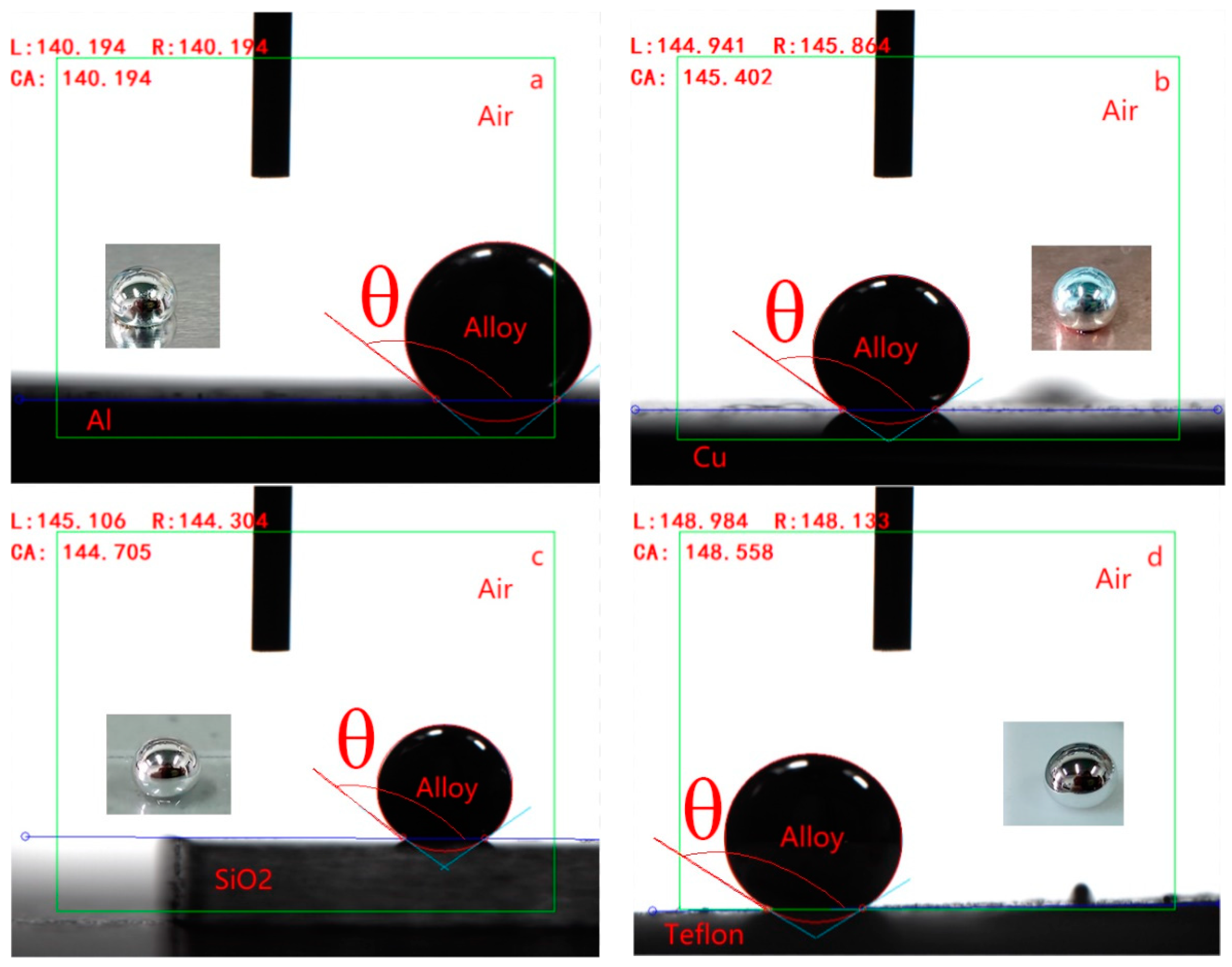
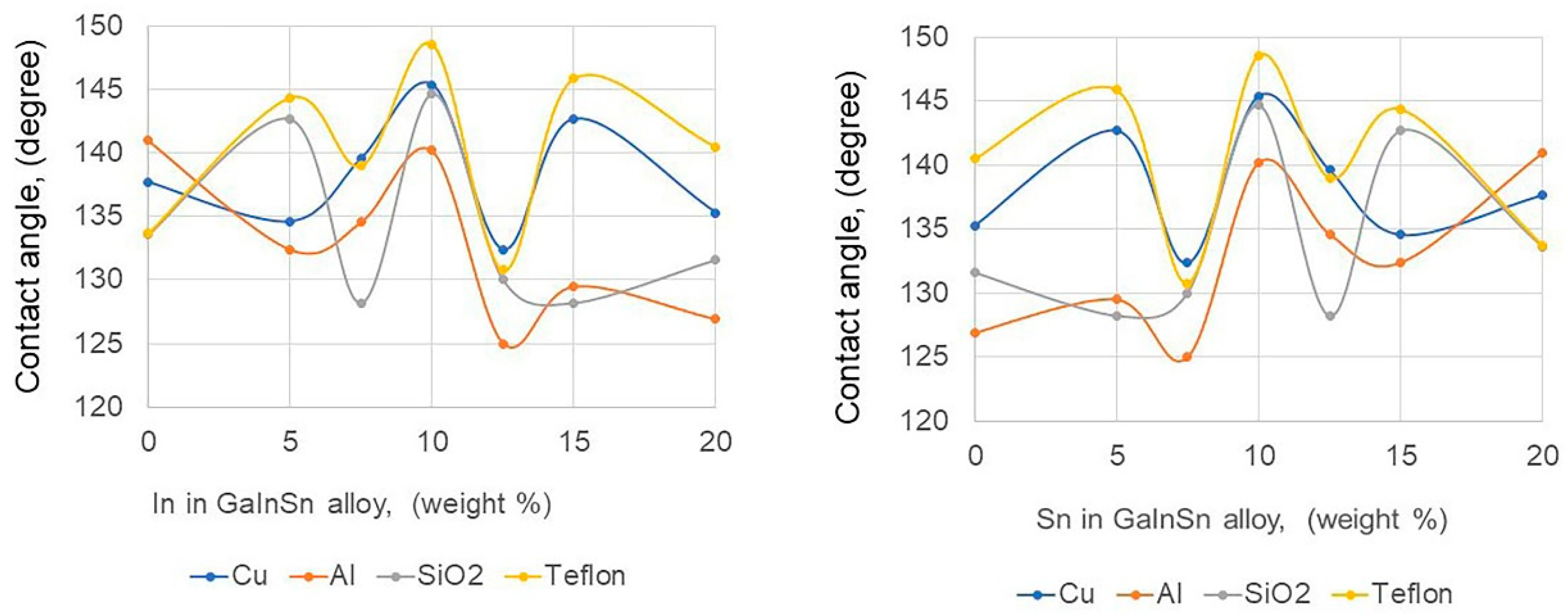
3.2. Contact Angle Measurement

The contact angle was measured as a quantitative measure of the surface’s wettability, represented by the angle at which a liquid or vapor interface interacted with a solid surface to check the fluid utilization in the canister or pipe. There is an elliptical method for fitting tangent lines to obtain contact angles. For example, when the surface tensions among the three solid, liquid, and gas phases are γSG, γSL, and γLG, respectively, and the surface roughness factor is β, the Young equation shows the following formula [41]:
β γ L G cos θ = γ S G γ S L
Figure 6 shows two examples of contact angle microscopic images of Ga80In10Sn10 on Al, Cu, silica (SiO2), and polymer Teflon substrates. When the substrates are very smooth, β is one. The surface tension of liquid metals was strongly affected by oxygen, and the surface tension γLG of the GaInSn [42] alloy was reported using the sessile drop method [43]. The surface tension of the GaInSn alloy was estimated to range from 550 to 600 mN/m at 300 K. Table 3 shows the contact angles of different alloy droplets on four kinds of substrates, including Cu, Al, silica, and Teflon plates. The average roughness of the four types of plates is also shown in Table 3, and they are very smooth by measuring with AFM (an atomic force microscope). The wetting angles of different gallium-based alloys indicated more than 90°. The contact angle Ga80In10Sn10 showed the largest contact angle compared with other Ga alloys on Cu, SiO2, and Teflon substrates except for Al. When the same Ga alloy was used to measure the contact angle on four plates, the larger contact angle showed the order of Teflon (PTFE) > Cu > SiO2 > Al or Teflon (PTFE) > Cu >Al > SiO2. However, they all had close contact angle values between 130° and 150°. Therefore, PTFE minimized the wettability and was suitable as the vessel [22] to be transferred into Ga alloy. On the other hand, Cu’s reaction with Ga [21] and Ga’s diffusion into Al [44] were reported, and Ga formed a eutectic with silicon near room temperature [45].
The contact angle of Galinstan on silicon was reported at 141° in an N2 atmosphere that did not contain oxidized Galinstan [46]. Therefore, the contact angle was higher than the value of Table 3. In addition, it was reported that Galinstan formed a fast oxide layer [47].
The contact angles of the measured samples on the four different substrates were all greater than 90°, and none were wetted with the substrates. Among them, the contact angle on the Teflon substrate was the largest, followed by the Cu substrate, Al, and SiO2 substrate. Compared with the listed Ga alloys, Ga90Sn10, Ga80Sn20, and Ga80In5Sn15 had larger contact angles on different substrates, and especially, Ga80In10Sn10 showed the largest contact angle. Figure 7 shows the effect of In and Sn content on the contact angle of other Ga80InSn alloys at 20 °C. The contact angle of the Ga80Sn20 alloy on four kinds of plate converged to 137.5 ± 3.9 when the Sn content increased to 20 wt.%, and the contact angle of Ga90Sn10 was almost the same 135.2 ± 2.9, as shown in Table 3. In comparison, the contact angle difference on four kinds of the plate increased as the In content rose to 20 wt.%. Especially the Ga80In10Sn10 alloy showed a larger contact angle for four types of substances. The change in alloying elements led to the change in metal atomic spacing, the metal bonding force, and contact angle. On the other hand, when those alloys were exposed on the plate in an air atmosphere for too long, such as one day, the gallium-based alloy reacted and eroded Al, Cu, and SiO2 substrates, causing damage to the substrates.
The above experiments found a large contact angle between the gallium-based alloy and these substrates. At the same time, the wetness was small, which is in line with the experimental expectation. However, gallium-based alloys easily eroded Al, Cu, and SiO2 substrates. Therefore, they are not suitable as storage containers or reaction containers for gallium-based alloys. Compared with them, Teflon is a better choice, with a wide range of use frequency and high and low temperatures, good chemical stability, outstanding surface non-stick, good lubrication, and atmospheric aging resistance. Therefore, Ga80In10Sn10 as the base carrier fluid and Teflon as the container of Ga alloy fluid could be used in various applications. For example, the Teflon pipe is convenient for the Ga alloy flow application.
Although the experimental results align with expectations, there are still some problems, including that the contact angle is too large. As a result, the oxidation of gallium-based alloys has been avoided as much as possible. However, exposure to the air during testing may result in some degree of oxidation in a short period, affecting the gallium-based alloy’s contact surface with substrates and resulting in larger contact angles.

3.3. Viscosity Measurement

Temperature dependence is shown in the Arrhenius-type formula [42].
μ T = η o exp E / R T
where μ T is the dynamic viscosity, T is the absolute temperature, η o is the pre-exponential constant, E is the activation energy, and R is the gas constant. When the temperature decreases, dynamic viscosity increases.
The viscosity test results of different gallium-based alloys are shown in Table 4.
On the other hand, the viscosity of gallium-based alloys through the capillary method at 20 °C is shown in Table S1. Those values were much smaller than the measurement result of Table 4 using a rheometer viscometer, as shown in Figure 2, which used 3(1/s) of the share rate. If the shear rate increased, the viscosity values would come near the capillary method values. In Table S1, the kinetic viscosity of Ga-based alloy was about 3 mPa·s, about three times higher than that of water, and showed well fluidity. This was slightly at odds with other literature, where there had been reports of Galinstan having a viscosity of 2.4 mPa·s [48] and also reported of Galinstan having a viscosity of 2.5 times that of water [49]. Still, neither of them indicated a specific temperature.
From the above experimental results, it can be found that the density of the Ga-based alloy is significantly larger than that of Ga (6.08 g/cm3 at 29.8 °C) [50], and the density of these alloys is similar from 6.6 to 6.8 g/cm3. (Ga80In10Sn10)97Al3 has the largest viscosity of 2.98 × 10⁴ mPa·s, and Ga80In7.5Sn12.5 has the smallest dynamic viscosity of 1.72 × 10⁴ mPa·s in Table 4. The viscosities of the gallium-indium-tin alloys are relatively similar, both being around 1.8 × 10⁴ mPa·s. The viscosity of the quaternary alloys is significantly higher than that of the ternary alloys, indicating that the addition of Al, Ge, and Zn has a greater effect on the internal structure of the alloys. In this experiment, NaOH was used to effectively remove the oxide film on the surface of the gallium-based alloy.
The shear stress, depending on the shear rate measured by parallel plates, is shown in Figure 8. The viscosity was measured using the HR 20-TA instrument, as shown in Figure 2, at 25 °C, with the shear rate rising from 1.0−6 to 10.0 1/s. All samples showed a similar shape of shear stress change. In the shear rate interval of 0–0.3 1/s, the shear stress of the samples increased with the increase in the shear rate. Between 0.3 and 3 1/s, the shear stress hardly changed. When the shear rate increased, some alloys flew out of the parallel plate, and the contact area between the alloy and the parallel plate also changed; therefore, the graph was shown in less than three, as shown in Figure 9. In general, these alloys are pseudoplastic, which is a fluid whose viscosity decreases as the shear rate increases. The vast majority of viscoelastic fluids are pseudoplastic. Here, a qualitative analysis was performed, and the quantitative analysis would be the future subject.
Yang et al. [51] tested many gallium-indium alloys and found that the critical strain amplitude was around 1% for all samples. This implied that the storage modulus, loss modulus, and loss factor were approximately constant in the linear region. To determine the amplitude of the strain range maintained by linear viscoelasticity, the strain scan experiments were carried out at 25 °C in a strain amplitude range from 0.01 to 100% at 1 rad/s and 10 rad/s for (Ga80In10Sn10)97Zn3, respectively, and the result was shown in Figure 9. The storage modulus (G’) refers to the amount of energy stored due to elastic (reversible) deformation when a material is deformed, which reflects the elasticity of the material; Loss modulus (G”) refers to the amount of energy lost due to the (irreversible) viscous deformation when the material is deformed, which reflects the viscosity of the material to investigate the liquid fluidity in the liquid metal application. When γ0 < 0.1, the storage modulus (G’) was stable, while the loss modulus (G”) showed some fluctuations in nonlinear viscoelasticity. When 0.1 ≤ γ0 ≤ 1, the G’ was more constant, while the G” increased linearly. The material loss factor (tanδ) is shown in the following formula:
T a n δ = G / G
When the loss factor is very small, the alloy shows elastic properties in this region because the Ga-based alloy has a strong surface tension due to a small shear strain amplitude. When γ0 > 1, the G’ decreased rapidly with the increase in the strain amplitude, while the G” showed a rising trend before falling. The loss factor increases with the increase in the strain amplitude. As a result, the energy storage capacity of the liquid alloy decreased rapidly, and the viscous effect gradually took the dominant position.
Figure 10 shows the storage modulus (G’) and loss modulus (G”) with an angular frequency from 0.1 to 100 rad/s at an applied strain amplitude of 0.1% at 25 °C. At 0.1% of the strain amplitude, the results for all alloys showed that the storage modulus (G’) was much larger than the loss modulus (G”). Ga-based (Ga80In10Sn10)97Zn3 alloy behaves more solidly than water. This indicates that the bulk phase was more inclined to elastic solids’ properties, and viscous fluids’ properties were weaker than those of elastic solids, indicating that some alloys may have been subjected to oxidation. When the alloy is oxidized, an oxide layer forms on the surface, which affects the contact surface between the alloy and the instrument, thus affecting the viscosity test. Alloys are prepared and stored in an oxygen-free environment; however, some tests do not guarantee oxygen-free conditions; therefore, the test was performed as soon as possible after the sample removal to minimize the effects of oxidation. In the frequency range of 0.1 to 100 rad/s, the G’ of the alloys hardly changed. At the same time, G” gradually decreased with the increase in frequency. The G” of the used alloys have relatively similar tendencies, and (Ga80In10Sn10)97Ge3 is the largest value, whereas Galinstan is the smallest value. While (Ga80In10Sn10)97Al3 has the largest G’ and Galinstan has the smallest G’. In addition, after adding Zn, Ge, and Al, it can be found that the G’ and G” of the four-element alloy are higher than those of the three-element alloy.

4. Conclusions

The low melting point of Ga alloy properties was investigated mainly for use “as a base carrier of ferrofluid” and for other applications. The Ga-based liquid alloy has high thermal conductivity compared with water and oil. As a result, the following characteristics were obtained:
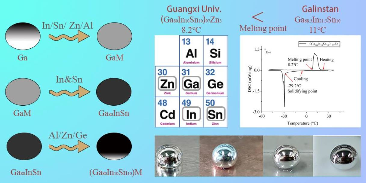
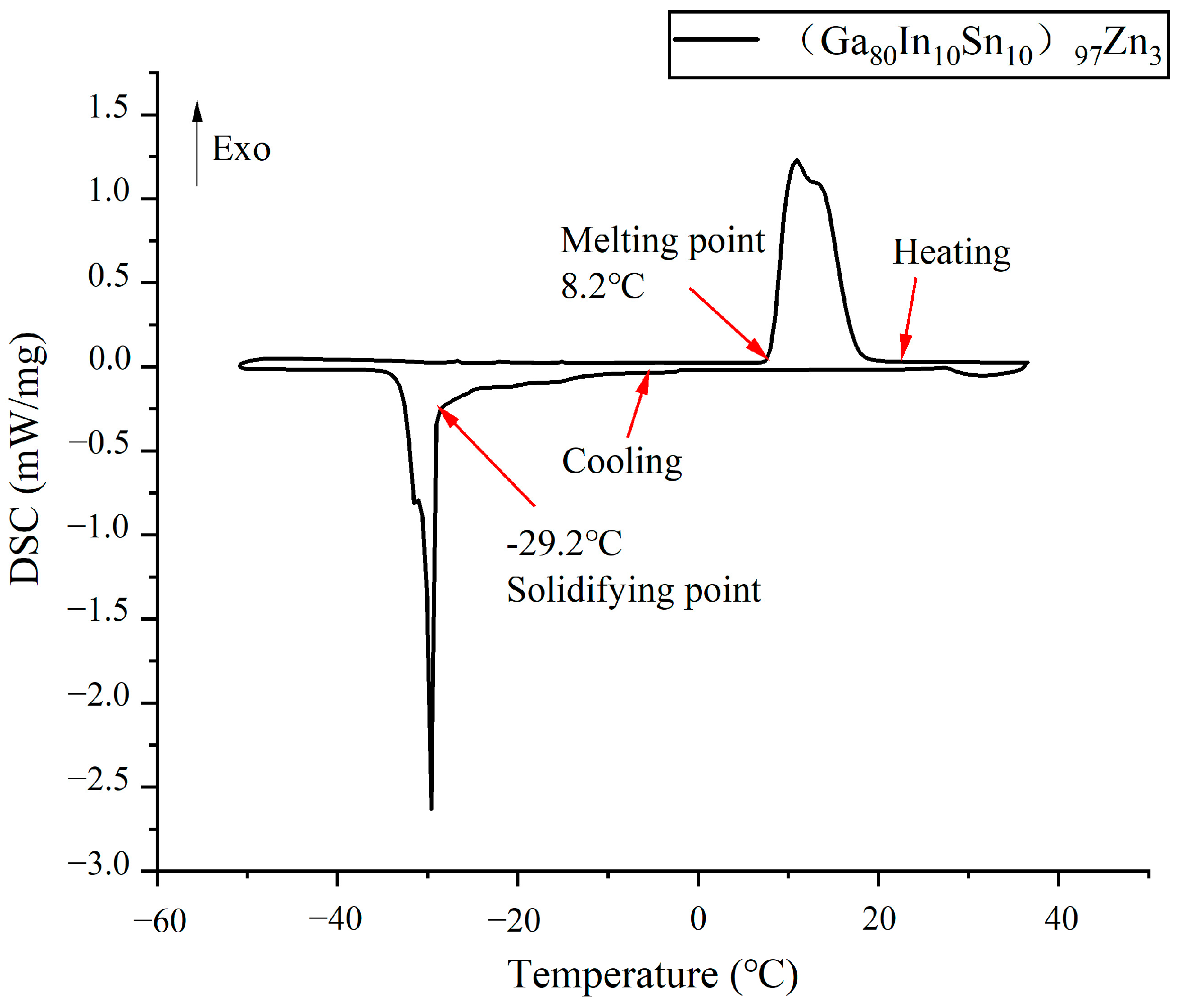
  • The (Ga80In10Sn10)97Zn3 alloy produced a low melting point of 8.2 °C in In, Sn, Zn, Ge, and Al of the Ga-based alloy, which was lower than that of Galinstan. This alloy could be utilized as a liquid in a wider temperature range.
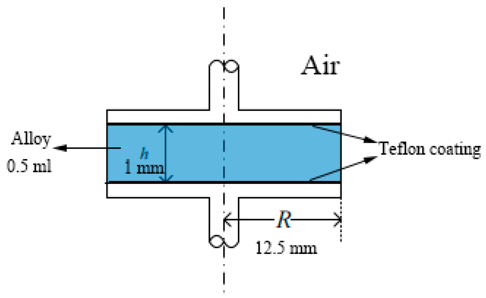
  • The Ga80In10Sn10 alloy had a larger contact angle of 140–150° on the Cu, Al, SiO2, and Teflon plate compared with other Ga-based alloys, and Teflon, for which the contact angle was 148.6°, was the best container, therefore, the Teflon pipe was convenient to use in the Ga alloy fluid flow application.
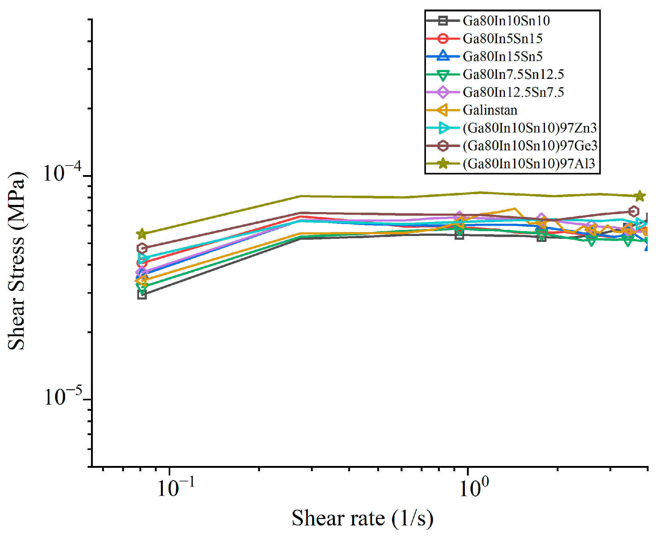
  • At 25 °C and a 3 1/s shear rate, (Ga80In10Sn10)97Al3 had the largest shear viscosity of 2.98 × 10⁴ mPa·s, and Ga80In7.5Sn12.5 had the lowest viscosity of 1.72 × 10⁴ mPa·s. In addition, the kinetic viscosity of Ga-based alloy was about 3 mPa·s, which was only three times that of water and showed well fluidity.
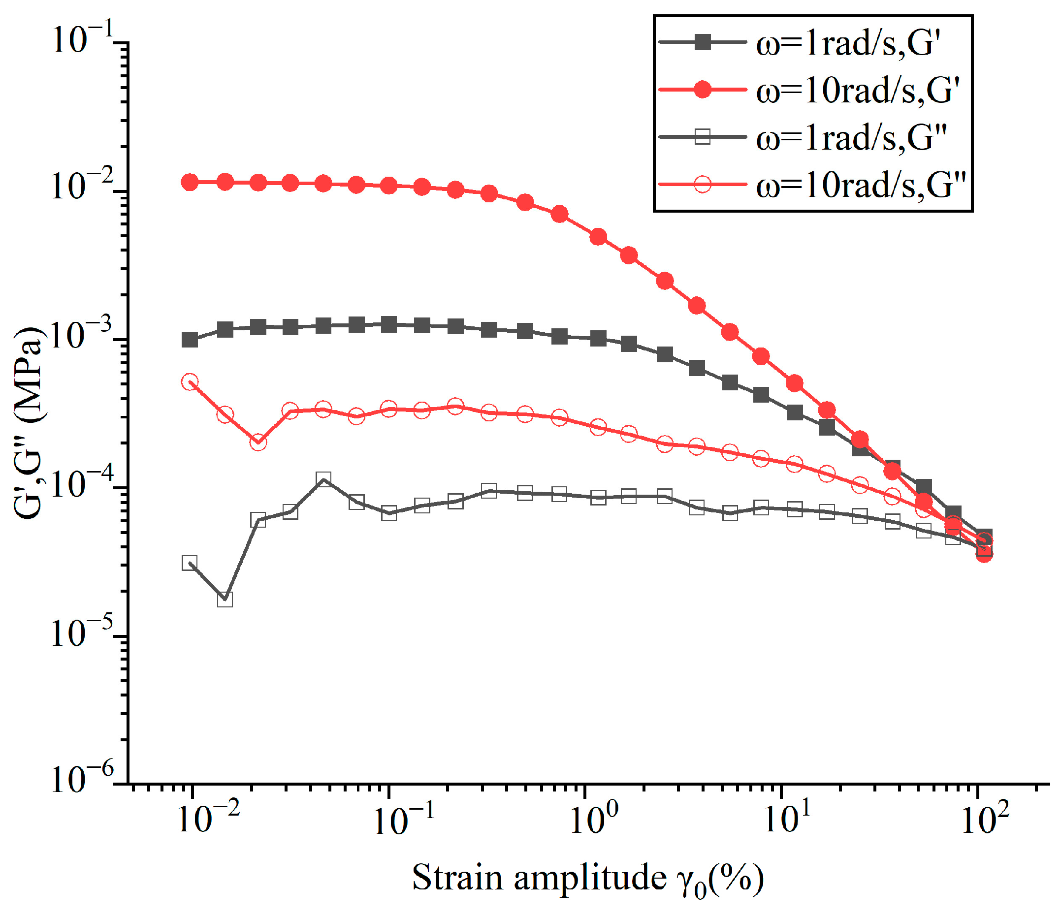
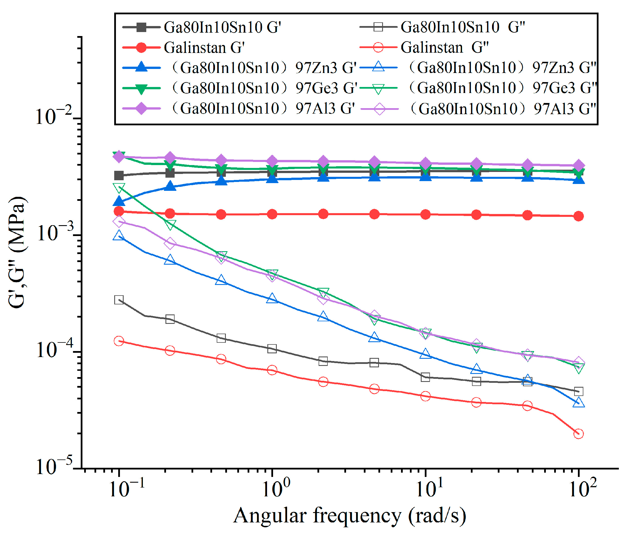
  • For the viscoelasticity of Ga-based (Ga80In10Sn10)97Zn3 alloy, the storage modulus (G’) was much larger than the loss modulus (G”) at a 0.1% strain amplitude, and it showed properties more similar to those of elastic solids that behaved more solidly than water.

Supplementary Materials

The following supporting information can be downloaded at: https://www.mdpi.com/article/10.3390/met13030615/s1, Table S1: The viscosity of gallium-based alloys by capillary method at 20 °C.

Author Contributions

J.S.: Data curation, investigation, writing—original draft. J.P.: investigation, data curation H.C.: investigation, methodology C.H.: data curation Y.W.: review and editing. G.D.: review and editing. T.F.: writing—review and editing. All authors have read and agreed to the published version of the manuscript.

Funding

This research was supported by special funding from the “Guangxi Bagui Scholars”.

Data Availability Statement

No new data were created.

Acknowledgments

We appreciate the special fund support provided by the “Guangxi Bagui scholars”.

Conflicts of Interest

The authors declare that they have no known competing financial interests or personal relationships that could have appeared to influence the work reported in this paper.

References

  1. Zhang, Y.; Liang, T.; Jusheng, M. Phase diagram calculation on Sn–Zn–Ga solders. J. Non-Cryst. Solids 2004, 336, 153–156. [Google Scholar] [CrossRef]
  2. Kalantar-Zadeh, K.; Tang, J.; Daeneke, T.; O’Mullane, A.P.; Stewart, L.A.; Liu, J.; Majidi, C.; Ruoff, R.S.; Weiss, P.S.; Dickey, M.D. Emergence of Liquid Metals in Nanotechnology. ACS Nano 2019, 13, 7388–7395. [Google Scholar] [CrossRef] [PubMed]
  3. Liu, J. Liquid metal machine is evolving to soft robotics. Sci. China Technol. Sci. 2016, 59, 1793–1794. [Google Scholar] [CrossRef] [Green Version]
  4. Liu, S.; Sun, X.; Kemme, N.; Damle, V.G.; Schott, C.; Herrmann, M.; Rykaczewski, K. Can liquid metal flow in microchannels made of its own oxide skin? Microfluid. Nanofluid. 2016, 20, 3. [Google Scholar] [CrossRef]
  5. Kwon, S.H.; Na, S.-M.; Flatau, A.B.; Choi, H.J. Fe–Ga alloy based magnetorheological fluid and its viscoelastic characteristics. J. Ind. Eng. Chem. 2020, 82, 433–438. [Google Scholar] [CrossRef]
  6. Wang, X.; Li, L.; Yang, X.; Wang, H.; Guo, J.; Wang, Y.; Chen, X.; Hu, L. Electrically Induced Wire-Forming 3D Printing Technology of Gallium-Based Low Melting Point Metals. Adv. Mater. Technol. 2021, 6, 2100228. [Google Scholar] [CrossRef]
  7. Dickey, M.D. Stretchable and Soft Electronics using Liquid Metals. Adv. Mater. 2017, 29, 1606425. [Google Scholar] [CrossRef]
  8. Daeneke, T.; Khoshmanesh, K.; Mahmood, N.; de Castro, I.A.; Esrafilzadeh, D.; Barrow, S.J.; Dickey, M.D.; Kalantar-Zadeh, K. Liquid metals: Fundamentals and applications in chemistry. Chem. Soc. Rev. 2018, 47, 4073–4111. [Google Scholar] [CrossRef]
  9. Fujita, T.; Park, H.-S.; Ono, K.; Matsuo, S.; Okaya, K.; Dodbiba, G. Movement of liquid gallium dispersing low concentration of temperature sensitive magnetic particles under magnetic field. J. Magn. Magn. Mater. 2011, 323, 1207–1210. [Google Scholar] [CrossRef]
  10. Gao, Y.; Liu, J. Gallium-based thermal interface material with high compliance and wettability. Appl. Phys. A 2012, 107, 701–708. [Google Scholar] [CrossRef]
  11. Ma, K.-Q.; Liu, J. Heat-driven liquid metal cooling device for the thermal management of a computer chip. J. Phys. D Appl. Phys. 2007, 40, 4722–4729. [Google Scholar] [CrossRef]
  12. Fumoto, K.; Ikegawa, M.; Kawanami, T. Heat Transfer Characteristics of a Thermo-sensitive Magnetic Fluid in Micro-channel. J. Therm. Sci. Technol. 2009, 4, 332–339. [Google Scholar] [CrossRef] [Green Version]
  13. Massart, R.; Rasolonjatovo, B.; Neveu, S.; Cabuil, V. Mercury-based cobalt magnetic fluids and cobalt nanoparticles. J. Magn. Magn. Mater. 2007, 308, 10–14. [Google Scholar] [CrossRef]
  14. Tang, S.-Y.; Khoshmanesh, K.; Sivan, V.; Petersen, P.; O’Mullane, A.P.; Abbott, D.; Mitchell, A.; Kalantar-Zadeh, K. Liquid metal enabled pump. Proc. Natl. Acad. Sci. USA 2014, 111, 3304–3309. [Google Scholar] [CrossRef] [PubMed] [Green Version]
  15. Cao, L.; Park, H.; Dodbiba, G.; Ono, K.; Tokoro, C.; Fujita, T. Keeping gallium metal to liquid state under the freezing point by using silica nanoparticles. Appl. Phys. Lett. 2011, 99, 143120. [Google Scholar] [CrossRef]
  16. De Castro, I.A.; Chrimes, A.F.; Zavabeti, A.; Berean, K.J.; Carey, B.J.; Zhuang, J.; Du, Y.; Dou, S.X.; Suzuki, K.; Shanks, R.A.; et al. A Gallium-Based Magnetocaloric Liquid Metal Ferrofluid. Nano Lett. 2017, 17, 7831–7838. [Google Scholar] [CrossRef] [PubMed]
  17. Yu, D.; Xue, Z.; Mu, T. Eutectics: Formation, properties, and applications. Chem. Soc. Rev. 2021, 50, 8596–8638. [Google Scholar] [CrossRef]
  18. Cao, K.B. New Systems Development and Fluidity Research of Low Melting Points Gallium-Based Liquid Metals; Yanshan University: Qinhuangdao, China, 2021. (In Chinese) [Google Scholar]
  19. Niu, H.; Bonati, L.; Piaggi, P.M.; Parrinello, M. Ab initio phase diagram and nucleation of gallium. Nat. Commun. 2020, 11, 2654. [Google Scholar] [CrossRef]
  20. Liu, S.; Sweatman, K.; McDonald, S.; Nogita, K. Ga-Based Alloys in Microelectronic Interconnects: A Review. Materials 2018, 11, 1384. [Google Scholar] [CrossRef] [PubMed] [Green Version]
  21. Sarfo, D.K.; Taylor, R.R.; O’Mullane, A.P. Investigating Liquid Metal Galinstan as a High Current Carrier and Its Interaction with Collector Electrodes. ACS Appl. Electron. Mater. 2020, 2, 2921–2928. [Google Scholar] [CrossRef]
  22. Evans, D.S.; Prince, A. Thermal analysis of Ga-In-Sn system. Met. Sci. 1978, 12, 411–414. [Google Scholar] [CrossRef]
  23. Liu, S.; Qu, D.; McDonald, S.; Gu, Q.; Matsumura, S.; Nogita, K. Intermetallic formation mechanisms and properties in room-temperature Ga soldering. J. Alloy. Compd. 2020, 826, 154221. [Google Scholar] [CrossRef]
  24. Yang, C.; Liu, Z.; Yu, M.; Bian, X. Liquid metal Ga-Sn alloy based ferrofluids with amorphous nano-sized Fe-Co-B magnetic particles. J. Mater. Sci. 2020, 55, 13303–13313. [Google Scholar] [CrossRef]
  25. Yu, M.; Bian, X.; Wang, T.; Wang, J. Metal-based magnetic fluids with core–shell structure FeB@SiO2 amorphous particles. Soft Matter 2017, 13, 6340–6348. [Google Scholar] [CrossRef] [PubMed]
  26. Dobosz, A.; Plevachuk, Y.; Sklyarchuk, V.; Sokoliuk, B.; Tkach, O.; Gancarz, T. Liquid Metals in High-Temperature Cooling Systems: The Effect of Bi Additions for the Physicochemical Properties of Eutectic Ga–Sn–Zn. J. Chem. Eng. Data 2019, 64, 404–411. [Google Scholar] [CrossRef]
  27. Gancarz, T. Physical, Thermal, Mechanical Properties, and Microstructural Characterization of Sn-9Zn-XGa Alloys. Met. Mater. Trans. A 2016, 47, 326–333. [Google Scholar] [CrossRef] [Green Version]
  28. Liu, T.; Sen, P.; Kim, C.-J. Characterization of Nontoxic Liquid-Metal Alloy Galinstan for Applications in Microdevices. J. Microelectromech. Syst. 2012, 21, 443–450. [Google Scholar] [CrossRef] [Green Version]
  29. Zeng, C.; Shen, J.; Zhang, J. High thermal conductivity in indium-based metal/diamond composites by good wettability of diamond with indium. Diam. Relat. Mater. 2021, 112, 108230. [Google Scholar] [CrossRef]
  30. Surmann, P.; Zeyat, H. Voltammetric analysis using a self-renewable non-mercury electrode. Anal. Bioanal. Chem. 2005, 383, 1009–1013. [Google Scholar] [CrossRef]
  31. Ding, Y.; Guo, X.; Qian, Y.; Xue, L.; Dolocan, A.; Yu, G. Room-Temperature All-Liquid-Metal Batteries Based on Fusible Alloys with Regulated Interfacial Chemistry and Wetting. Adv. Mater. 2020, 32, e2002577. [Google Scholar] [CrossRef]
  32. Ding, Y.; Guo, X.; Yu, G. Next-Generation Liquid Metal Batteries Based on the Chemistry of Fusible Alloys. ACS Cent. Sci. 2020, 6, 1355–1366. [Google Scholar] [CrossRef] [PubMed]
  33. Ge, H.; Li, H.; Mei, S.; Liu, J. Low melting point liquid metal as a new class of phase change material: An emerging frontier in energy area. Renew. Sustain. Energy Rev. 2013, 21, 331–346. [Google Scholar] [CrossRef]
  34. Guo, J.; Cheng, J.; Tan, H.; Zhu, S.; Qiao, Z.; Yang, J.; Liu, W. Al-Doped Ga-Based Liquid Metal: Modification Strategy and Controllable High-Temperature Lubricity through Frictional Interface Regulation. Langmuir 2019, 35, 6905–6915. [Google Scholar] [CrossRef] [PubMed]
  35. Krisnadi, F.; Nguyen, L.L.; Ankit; Ma, J.; Kulkarni, M.R.; Mathews, N.; Dickey, M.D. Directed Assembly of Liquid Metal–Elastomer Conductors for Stretchable and Self-Healing Electronics. Adv. Mater. 2020, 32, 2001642. [Google Scholar] [CrossRef] [PubMed]
  36. So, J.-H.; Koo, H.-J.; Dickey, M.D.; Velev, O.D. Ionic Current Rectification in Soft-Matter Diodes with Liquid-Metal Electrodes. Adv. Funct. Mater. 2012, 22, 625–631. [Google Scholar] [CrossRef]
  37. Yi, L.; Ding, Y.; Yuan, B.; Wang, L.; Tian, L.; Chen, C.; Liu, F.; Lu, J.; Song, S.; Liu, J. Breathing to harvest energy as a mechanism towards making a liquid metal beating heart. RSC Adv. 2016, 6, 94692–94698. [Google Scholar] [CrossRef]
  38. Zhang, J.; Yao, Y.; Sheng, L.; Liu, J. Self-Fueled Biomimetic Liquid Metal Mollusk. Adv. Mater. 2015, 27, 2648–2655. [Google Scholar] [CrossRef]
  39. Doudrick, K.; Liu, S.; Mutunga, E.M.; Klein, K.L.; Damle, V.; Varanasi, K.K.; Rykaczewski, K. Different Shades of Oxide: From Nanoscale Wetting Mechanisms to Contact Printing of Gallium-Based Liquid Metals. Langmuir 2014, 30, 6867–6877. [Google Scholar] [CrossRef] [PubMed]
  40. Jacob, A.R.; Parekh, D.P.; Dickey, M.D.; Hsiao, L.C. Interfacial Rheology of Gallium-Based Liquid Metals. Langmuir 2019, 35, 11774–11783. [Google Scholar] [CrossRef] [PubMed]
  41. Hiemen, P.C. Principle of Colloid and Surface Chemistry; CRC: Boca Raton, FL, USA, 1997. [Google Scholar]
  42. Plevachuk, Y.; Sklyarchuk, V.; Eckert, S.; Gerbeth, G.; Novakovic, R. Thermophysical Properties of the Liquid Ga–In–Sn Eutectic Alloy. J. Chem. Eng. Data 2014, 59, 757–763. [Google Scholar] [CrossRef]
  43. Lee, J.; Kiyose, A.; Nakatsuka, S.; Nakamoto, M.; Tanaka, T. Improvements in Surface Tension Measurements of Liquid Metals Having Low Capillary Constants by the Constrained Drop Method. ISIJ Int. 2004, 44, 1793–1799. [Google Scholar] [CrossRef] [Green Version]
  44. An, Q.; Jin, Z.; Li, N.; Wang, H.; Schmierer, J.; Wei, C.; Hu, H.; Gao, Q.; Woodall, J.M. Study on the liquid phase-derived activation mechanism in Al-rich alloy hydrolysis reaction for hydrogen production. Energy 2022, 247, 123489. [Google Scholar] [CrossRef]
  45. Sunkara, M.K.; Sharma, S.; Miranda, R.; Lian, G.; Dickey, E.C. Bulk synthesis of silicon nanowires using a low-temperature vapor–liquid–solid method. Appl. Phys. Lett. 2001, 79, 1546–1548. [Google Scholar] [CrossRef] [Green Version]
  46. Davis, E.; Ndao, S. On the Wetting States of Low Melting Point Metal Galinstan® on Silicon Microstructured Surfaces. Adv. Eng. Mater. 2018, 20, 1700829. [Google Scholar] [CrossRef]
  47. Chen, Y.; Wagner, J.L.; Farias, P.A.; DeMauro, E.P.; Guildenbecher, D.R. Galinstan liquid metal breakup and droplet formation in a shock-induced cross-flow. Int. J. Multiph. Flow 2018, 106, 147–163. [Google Scholar] [CrossRef]
  48. Hayashi, Y.; Saneie, N.; Yip, G.; Kim, Y.J.; Kim, J.-H. Metallic nanoemulsion with galinstan for high heat-flux thermal management. Int. J. Heat Mass Transf. 2016, 101, 1204–1216. [Google Scholar] [CrossRef]
  49. Lam, L.S.; Hodes, M.; Enright, R. Analysis of Galinstan-Based Microgap Cooling Enhancement Using Structured Surfaces. J. Heat Transf. 2015, 137, 091003. [Google Scholar] [CrossRef]
  50. Haynes, W.M. CRC Handbook of Chemistry and Physics; CRC: Boca Raton, FL, USA, 2020; p. 2674. [Google Scholar]
  51. Yang, Y.; Sun, S.; Tang, S.Y.; Li, W.; Zhang, S. Viscoelastic Properties of Gallium-Indium Alloy. Appl. Rheol. 2018, 28, 42903. [Google Scholar] [CrossRef]
Disclaimer/Publisher’s Note: The statements, opinions, and data contained in all publications are solely those of the individual author(s) and contributor(s) and not of MDPI and/or the editor(s). MDPI and/or the editor(s) disclaim responsibility for any injury to people or property resulting from any ideas, methods, instructions, or products referred to in the content.
Figure 1. Gallium crystal.
Metals 13 00615 g001
Figure 2. Test parallel plates.
Metals 13 00615 g002
Figure 3. DSC test curve of (Ga80In10Sn10)97Zn3..
Metals 13 00615 g003
Figure 4. (a) Melting point of GaIn alloys (with error bar); (b) Melting point of binary gallium alloys.
Metals 13 00615 g004
Figure 5. (a) Melting point diagram of Ga-In-Sn alloy; (b) Enlarged figure.
Metals 13 00615 g005
Figure 6. Contact angle between Ga80In10Sn10 and (a) Al substrate, (b) Cu substrate, (c) SiO2 substrate, (d) Teflon substrate (20 °C).
Metals 13 00615 g006
Figure 7. Effect of In and Sn content on the contact angle of different gallium alloys (80 wt.% of Ga in Ga80InSn at 20 °C).
Metals 13 00615 g007
Figure 8. Shear stress is plotted as a function of the shear rate for gallium-based alloys.
Metals 13 00615 g008
Figure 9. Storage modulus (G’) and loss modulus (G”) are plotted as a function of the strain amplitude of (Ga80In10Sn10)97Zn3 at 1 and 10 rad/s, respectively.
Metals 13 00615 g009
Figure 10. Storage modulus (G’) and loss modulus (G”) are plotted as a function of the angular frequency for gallium-based alloys.
Metals 13 00615 g010
Table 1. Research status of the melting point of gallium-based liquid metal (each value in the metal column means the weight percentage).
MetalMelting Point (°C)
Pure Ga29.76 [20]
Galinstan
(Ga68.5In21.5Sn10)
11 [5,20] (solidify point −19 [21,22])
(Ga78.3In14.9Sn6.8)13.2 [8]
Galinstan + 0.2Gd13.2 [16]
Galinstan + 1.2Gd13.7 [16]
Galinstan + 2.3Gd16.3 [16]
Ga75.5In24.515.4 [23]
Ga90Zn1024.7 [20]
Ga62Sn32Bi6128 [20]
Ga86.5Sn13.520.5/21 [20]
Ga91.6Sn8.420.6 [24]
Ga85.8In14.2Liquid at room temperature [25]
Ga91.5Sn8.5
Ga77.2In14.4Sn8.4
Ga–In binary eutectic15.3 [26]
Ga–Sn binary eutectic20.5 [26]
Al–Ga–Sn eutectic19 [26]
Al–Ga–In eutectic15 [26]
Al–Ga–In–Sn eutectic10.7 [26]
Al–In binary eutectic156 [26]
Al–Sn binary eutectic228 [26]
SnZn eutectic198 [26]
SnZn + 1.8 Ga195 [27]
SnZn + 2 Ga199 [27]
SnZn + 3 Ga195 [27]
SnZn + 4 Ga188 [27]
SnZn + 6 Ga174 [27]
SnZn + 8 Ga155 [27]
Table 2. Gallium-based alloy melting point with different elements (each value in the metal column means weight percentage.).
AlloyMelting Point (°C)Melting Width (°C)
Ga90In1017.610.3
Ga80In2017.99.7
Ga70In3017.710.2
Ga60In4017.511.0
Ga50In5017.59.8
Ga40In6017.710.6
Ga30In7018.010.8
Ga20In80Solid at room temperature
Ga10In90
Ga90Sn1022.511.4
Ga80Sn2022.110.5
Ga70Sn3022.411.5
Ga60Sn4022.311.0
Ga50Sn5022.311.2
Ga40Sn60Solid at room temperature
Ga30Sn70
Ga20Sn80
Ga10Sn90
Ga90Zn1026.79.6
Ga80Zn2026.810.0
Ga70Zn3026.89.4
Ga60Zn40Solid at room temperature
Ga50Zn50
Ga90Al10
Ga95Al5
Ga80In5Sn1519.610.2
Ga80In10Sn1011.79.3
Ga80In15Sn514.910.1
Ga80In7.5Sn12.517.511.2
Ga80In12.5Sn7.516.210.5
(Ga80In10Sn10)97Zn38.28.9
(Ga80In10Sn10)97Ge310.18.3
(Ga80In10Sn10)97Al39.98.2
Table 3. Contact angles of different gallium-based alloys on different plates at 20 °C.
AlloyCuAlSiO2Teflon
Average
roughness
7.45 nm7.54 nm0.0031 nm1.73 nm
Ga90In10132.8°127.2°130.7°143.2°
Ga80In20135.3°126.9°131.6°140.5°
Ga90Sn10136.5°135.2°132.5°136.5°
Ga80Sn20137.7°141.0°133.6°137.7°
Ga80In10Sn10145.4°140.2°144.7°148.6°
Ga80In5Sn15134.6°132.4°142.7°144.4°
Ga80In15Sn5142.7°129.5°128.2°145.9°
Ga80In7.5Sn12.5139.6°134.6°128.2°139.0°
Ga80In12.5Sn7.5132.4°125.0°130.3°130.8°
Galinstan (Ga68.5In21.5Sn10)142.4°135.0°129.8°143.0°
(Ga80In10Sn10)97Zn3132.0°131.1°128.6°135.0°
(Ga80In10Sn10)97Ge3134.6°133.8°131.5°138.7°
(Ga80In10Sn10)97Al3138.3°135.3°125.9°142.4°
Table 4. The viscosity of gallium-based alloys by rheometer (25 °C, shear rate = 3 1/s).
AlloyDensity
(g/cm3)
Viscosity
(mPa·s)
Ga80In10Sn106.721.87 × 104
Ga80In15Sn56.751.78 × 104
Ga80In5Sn156.601.77 × 104
Ga80In12.5Sn7.56.761.85 × 104
Ga80In7.5Sn12.56.681.72 × 104
Galinstan (Ga68.5In21.5Sn10)6.491.87 × 104
(Ga80In10Sn10)97Zn36.792.15 × 104
(Ga80In10Sn10)97Ge36.672.51 × 104
(Ga80In10Sn10)97Al36.592.98 × 104
Disclaimer/Publisher’s Note: The statements, opinions and data contained in all publications are solely those of the individual author(s) and contributor(s) and not of MDPI and/or the editor(s). MDPI and/or the editor(s) disclaim responsibility for any injury to people or property resulting from any ideas, methods, instructions or products referred to in the content.

