Review

A Review on Processing–Microstructure–Property Relationships of Al-Si Alloys: Recent Advances in Deformation Behavior

Department of Mechanical and Industrial Engineering, Toronto Metropolitan University (Formerly Ryerson University), Toronto, ON M5B 2K3, Canada
*
Author to whom correspondence should be addressed.
Metals 2023, 13(3), 609; https://doi.org/10.3390/met13030609
Submission received: 11 February 2023 / Revised: 10 March 2023 / Accepted: 11 March 2023 / Published: 17 March 2023

Abstract

:
While research on lightweight materials has been carried out for decades, it has become intensified with recent climate action initiatives leading pathways to net zero. Aluminum alloys are at the pinnacle of the light metal world, especially in the automotive and aerospace industries. This review intends to highlight recent developments in the processing, structure, and mechanical properties of structural Al-Si alloys to solve various pressing environmental issues via lightweighting strategies. With the excellent castability of Al-Si alloys, advancements in emerging casting methods and additive manufacturing processes have been summarized in relation to varying chemical compositions. Improvements in thermal stability and electrical conductivity, along with superior mechanical strength and fatigue resistance, are analyzed for advanced Al-Si alloys with the addition of other alloying elements. The role of Si morphology modification, along with particle distribution, size, and precipitation sequencing, is discussed in connection with the improvement of static and dynamic mechanical properties of the alloys. The physics-based damage mechanisms of fatigue failure under high-cycle and low-cycle fatigue loading are further elaborated for Al-Si alloys. The defect, porosity, and surface topography related to manufacturing processes and chemical compositions are also reviewed. Based on the gaps identified here, future research directions are suggested, including the usage of computational modeling of microstructures and the integration of artificial intelligence to produce mass-efficient and cost-effective solutions for the manufacturing of Al-Si alloys.

1. Introduction

Within the last few decades, there has been a tremendous increase in demand for lightweight materials, such as aluminum (Al), magnesium (Mg), and titanium (Ti), in the automotive and aerospace industries. The primary focus of these industries is to manifest their technological advancements in energy efficiency to attain the goal of ‘net-zero’ emissions by 2050 [1,2]. Leading a pathway to net zero involves steps taken by governments and industries worldwide to decrease carbon-based fuel consumption, which leads to a reduced carbon footprint [3,4]. Canadian emissions of greenhouse gases (GHGs) have been recently projected by the government up to 2030 with several climate action amendments in act as shown in Figure 1a [3]. With an expected reduction of 40% in GHG emissions by 2030 from the 2005 level, the Pan-Canadian Framework (2016) and Strengthened Climate Plan (2020) represent the newer measures and strategies undertaken by the government. Altering the materials and manufacturing of fuel-driven vehicles, automotive industries have redirected their attention to the development of hybrid or battery-powered electric vehicles (BEVs) in the last decade [5]. Premier auto-giants such as Audi, GM, Nissan, Volkswagen, Chevrolet, Tesla, etc., have shown an eminent shift towards the manufacturing of EVs [6]. A recent study summarized by Ducker Frontier 2020 [7] showed a statistical increase in the use of cast Al alloys from 1979 to 2020, with further projections up to 2030. By looking at the global metal casting production of 109 million metric tons (MT) in 2019, Al alloys constituted about 17 million MT [2]. It was shown that the global market for automotive Al products will reach $ 109.7 billion by 2026, with a compound annual growth rate (CAGR) of 8.30% [8,9,10]. A recent study confirmed the progress of Al alloys in the global market, which was already estimated to be $ 131 billion in 2022, crossing the mark set previously as shown in Figure 1b. Furthermore, it is projected to increase at a CAGR of 8.1% to $ 287 billion by 2032 [11]. Over the coming years, the growth of electric vehicles will increase the demand of cast Al alloys, such as Al-Si, Al-Si-Cu, Al-Si-Ag, and Al-Si-Sn alloys, in the market [12]. Surging investments in housing activities globally have been identified as a potential trend that would drive sales of high-strength Al-Si alloys, especially in the high-growth region of Asia Pacific. The global Al-Si alloy market is also projected to grow at a CAGR of 2.84% during the forecast period of 2022−2030 [13].
Developments in casting technology, solidification fundamentals, and process control parameters for Al-Si alloys have been well documented in several handbooks and articles since the 1960s [14,15,16,17,18,19,20,21,22]. Al-Si alloys are known to have low density, high specific strength, high ductility, good castability, high thermal conductivity, high corrosion resistance, cosmetic surface quality, resistance to hot tearing, etc., which makes them suitable for large-scale automotive and aerospace applications [23,24]. Figure 1c shows the global market share of Al die-cast alloys based on their application in different sectors [9]. The transportation sector is a major consumer for such alloys, with building and construction securing the second spot [9]. Apart from conventional casting techniques, a significant rise in the production of Al-10%Si-Mg or Al-12%Si alloys in the additive manufacturing sector has gained popularity in recent years [25]. Though these processes have not yet overcome some shortcomings, such as mass production relative to die-casting, intense research is still ongoing.
A recent review by Li et al. [26] summarized Al-Si alloys manufactured through conventional casting processes with high electrical conductivity, based upon the International Annealed Copper Standard (IACS). The chemical modifications, alloying additions, electrical properties, and thermal stability of Al-Si alloys have been well documented in [27,28]. A lot of discussion on automotive, aeronautical, and aerospace applications of Al-Si alloys, along with manufacturing and mechanical properties, is presented in a book by Hernandez et al. [29]. However, only limited literature surveys are available on the fatigue behavior and deformation mechanisms of these alloys [30,31]. The principal aim of this article is to provide a comprehensive review on recent developments from alloy chemistry-designing to structure-property relationships of Al-Si alloys in the last two decades. Recent changes and future challenges faced by manufacturing routes are discussed to consider the cost effectiveness and mass efficiency of Al-Si alloys. Deformation behavior of Al-Si alloys under static uniaxial loading are summarized for better understanding. A critical review on high-cycle fatigue and low-cycle fatigue at room temperature and elevated temperatures are highlighted in this review. Physics-based theoretical and microstructural models are also discussed, along with fatigue crack initiation, propagation, and damage mechanisms in Al-Si alloys. This review is able to bridge the gap between cyclic deformation behavior/mechanisms and microstructure/fabrication defects, which will yield better design and optimization of structural Al-Si alloys for safe and durable industrial applications. For the brevity of this review article, all the Al alloys considered have Si > 5 wt.%, unless otherwise stated, and are referred to as Al-Si alloys.

2. Advancements in Al-Si Alloys

2.1. Overview

Applications involving lightweight Al castings have been increasing over time, more so now than before, with the growth of recycled and secondary-grade Al alloys. Aerospace Al alloys are still produced from primary sources to avoid any unnecessary chemical defects from recycled ones. However, automotive industries are relying more on scrap Al supply [24]. ‘Lightweighting’ and ‘recycling’ are two major terms that have been driving Al industries towards the pathway to net-zero emissions. Some important applications of Al-Si alloys in different sectors, along with recent developments towards green energy and environmental sustainability, are discussed in this section.

2.2. Applications of Al-Si Alloys

2.2.1. Automotive Applications

In a typical passenger vehicle, such as a car, minivan, or light truck, Al castings can be found in several parts, such as the roof brackets, door handles, engine blocks, pistons, powertrain, battery compartments, wheels, chassis, space frames, etc. These components after manufacturing need to satisfy ASTM specifications for mechanical properties, porosity limit, roughness, dimensional stability, and corrosion resistance. As the growth of electric vehicles (EVs) clouds over conventional internal-combustion-engine models, Al-Si alloys have been able to find their applications prominently in these sectors.

Internal Combustion Engine Vehicles

Replacing heavier cast iron and steel components with Al-Si alloys in North American vehicles has led to the satisfaction of Corporate Fuel Average Economy (CAFE) standards. This allows customers to experience vehicles with reduced weight and increased fuel economy [32]. Powertrain components such as the V8 engine block, which is made out of Al-Si castings, weigh ~30–50 kg, compared to gray cast iron parts, weighing ~70–120 kg [33,34]. Recent developments have shown that the addition of transition metals and rare-earth elements, such as Zr, Ti, Sc, V, etc., to Al-Si alloys is able to improve the high temperature and wear performance of the engine component [27,35,36,37,38]. Increased power rating of powertrain components is possible with the help of Al alloys, leading to higher thermal and electrical conductivity [27,39]. Controlled process parameters have allowed engineers to manufacture alloys such as the low-iron-containing Silafont®-36 alloy, which has higher castability and ductility and is suitable for suspensions and space-frame members [40]. Figure 2a–d,f–i show some specific components, such as steering columns, engine cradle, shock tower, and front sections fabricated with Al-Si alloys, such as AuralTM-2, Castasil®-37, Silafont®-36, MercalloyTM-367, and Alcoa’s C601/611 alloys [2,41,42,43]. Emerging manufacturing processes, such as high-pressure die-casting, is able to streamline the production of thinner and thicker parts with high integrity and stability. It is expected that the usage of such processes will increase towards 2040 for automotive Al castings [44].

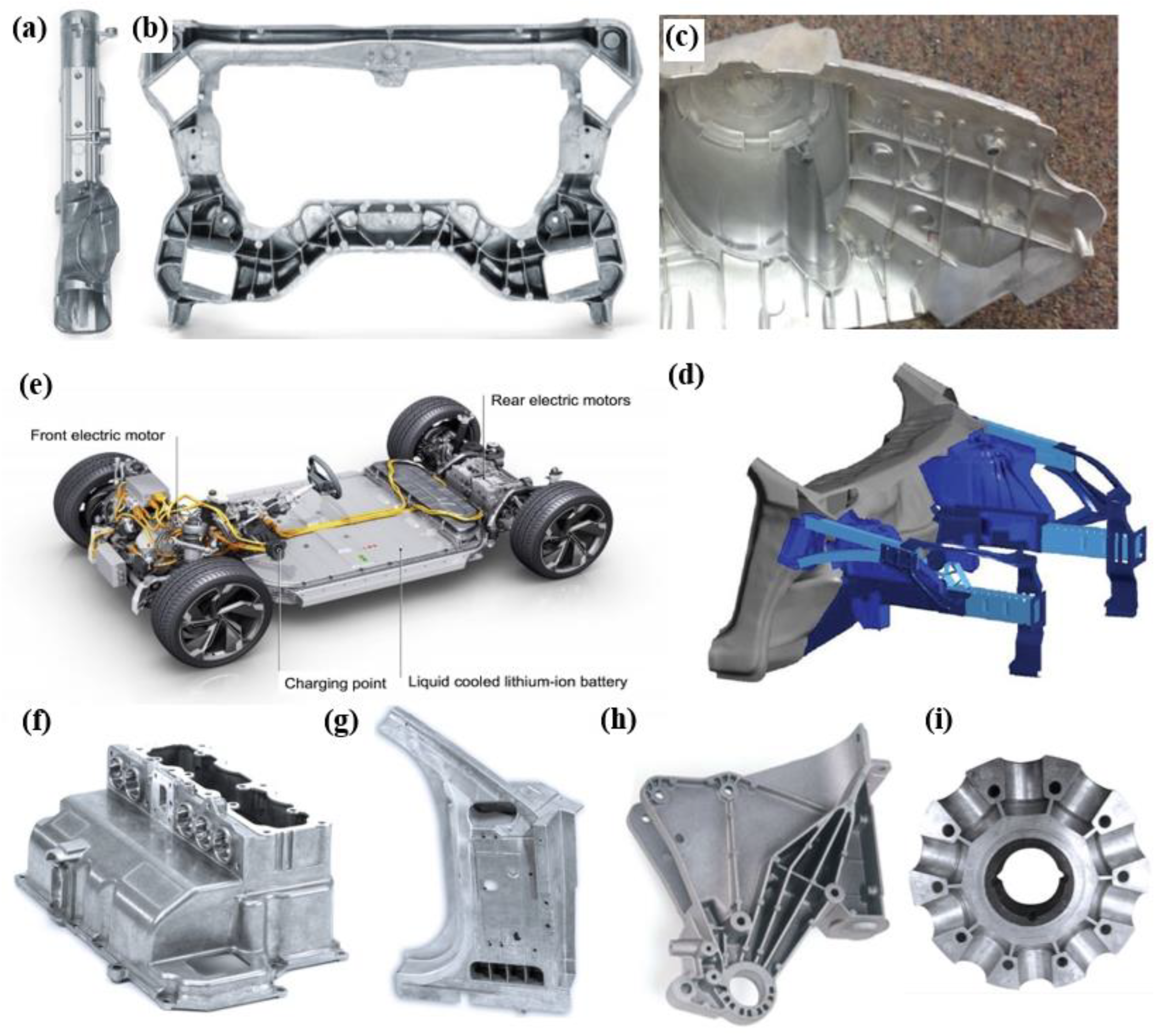
Hybrid and Electric Vehicles

The market for hybrid and full electric vehicles has grown exponentially within the last decade, which has resulted in the downsizing of internal-combustion-engine parts, such as engine blocks and the number of cylinders. New structural components to house batteries are being designed to satisfy safety and reliability demands. Figure 2e shows the powertrain components for an Audi EV model fabricated with structural Al alloy die-castings [45]. Companies such as Volvo are trying to replace extruded and stamped sheets into a single giant piece Al casting, also known as mega-giga casting technology [44]. It has been reported that Al-using EVs emit 1.5 tons less GHGs over their complete life cycle than steel- or cast-iron-using EVs [46]. Gomes et al. [47] studied Ag-containing Al-Si alloys to replace normal Al-Si castings for EVs, which improved the electrical conductivity, another beneficial property needed for battery-driven vehicles. Tesla™ has been trying to create alloys with high yield strength and conductivity, while being resistant to hot tearing for usage in newly developed EVs as die-casting drive unit components [48]. Studies leading to the development of Al-Si alloys with the addition of Cu, Mg, Mn, Ni, Sr, etc., which increase electrical conductivity along with strength and ductility, are some of the major foci for automotive industries and researchers [26].

2.2.2. Aeronautical and Aerospace Applications

Aerospace Al-Si alloy castings generally have a longer life than those used in automotive applications due to higher fatigue resistance and corrosion resistance. Other traits of Al-Si alloys include improved static strength, resistance to crack growth, damage tolerance, stress corrosion, and fracture toughness [49]. The Advisory Council for Aeronautics Research in Europe (ACARE) reported a significant 38% reduction in CO2 emissions and a 37% reduction in the perceived noise against a goal of 50% for both criteria by 2020 [50]. The common fabrication methods to make complex structural Al-Si alloy components used by aerospace giants such as Boeing, Airbus, Bombardier, etc., are precision sand casting and investment casting processes. This helps to reduce wrought Al alloy welding, which leads to 50% weight reduction and lower component cost [24].

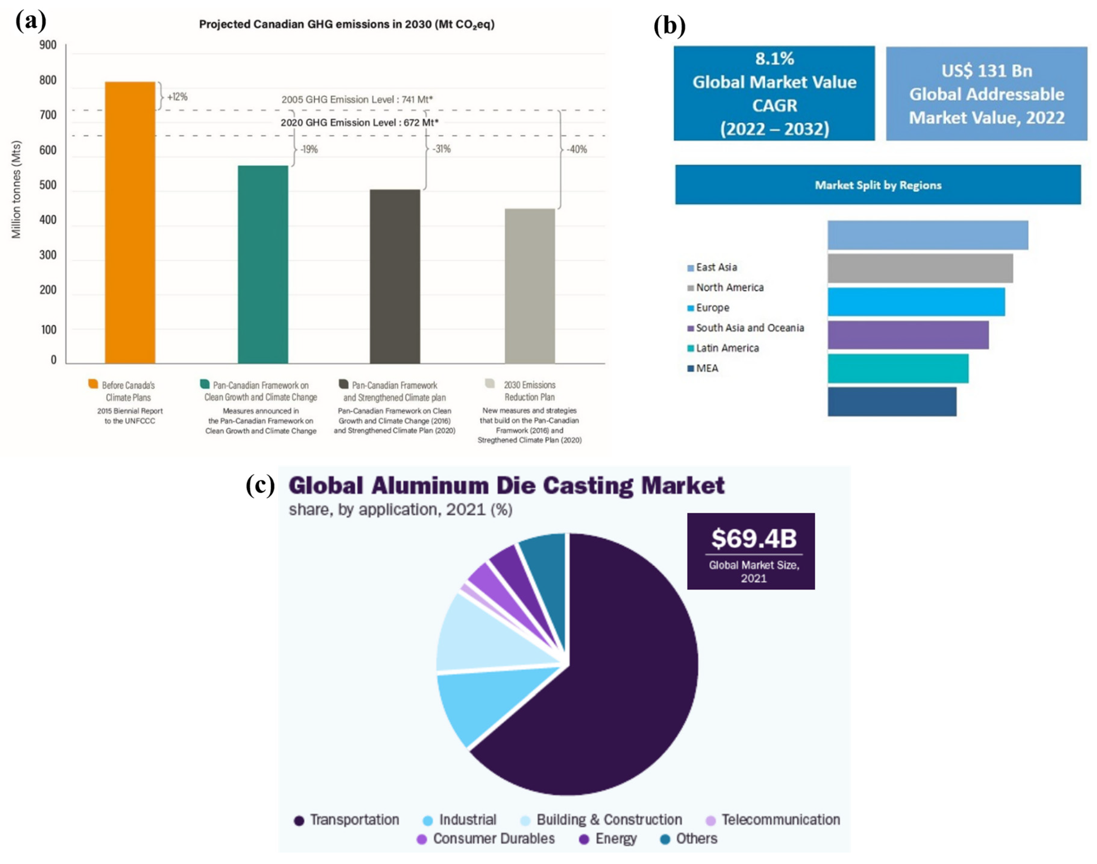
2.3. Achievements for the Pathway to Net-Zero Emissions

The pathway to net zero simply means cutting GHG emissions to as close to zero as possible, while allowing remaining emissions to be re-absorbed by nature. The transportation sector shares a major portion of CO2 emissions, about 7.2 gigatons recorded in 2020 [4]. The North American automotive industry has set a goal to increase Al content to 250 kg per vehicle by the year 2026, an increase of 12% from 2020 [51]. Referring to Figure 1a, the Canadian government aims to nullify GHG emissions by 2050 with the help of the 2030 Emissions Reduction Plan [3]. Studies have shown that 140 kg of Al in an average car result in an annual average fuel saving of 65 L [43]. From 2010 to 2020, average CO2 emissions from European Al-using vehicles had also decreased from 142 g/km to 95 g/km (or 3.9% per year), which shows progress towards environmental sustainability and a reduction in carbon footprint [52]. The following sections discuss the manufacturing, microstructures, and mechanical properties substantiating the advantages of Al-Si alloys.
Figure 2. Automotive applications for Al-Si alloys, such as (a) steering column, (b) engine cradle [40], (c) shock tower [2], (d) front section [52], (e) Li-ion battery compartment for Audi e-tron [45], (f) upper safety housing for high-voltage heat plug connectors, (g) A-pillar, (h) truck cab tilting joint, and (i) ventilator hub [40]. Reproduced with permission from Elsevier and open-access websites.
Metals 13 00609 g002

3. Fabrication Techniques

Aluminum-Silicon (Al-Si) alloys prefer the casting process due to the presence of Si, which makes them extremely castable. Selection of the casting process involves many factors and is primarily driven by cost efficiency. The processes become distinguishable when classification is based on either automotive or aerospace requirements for Al-Si casting products. In the case of automotive industries, higher production cycles are needed to meet the demand of engine plants or automotive assemblers, whereas aerospace casting applications demand more component complexity with strict dimensional stability, thermal stability, and mechanical strength [53]. Various casting processes are used to manufacture Al-Si alloys; however, only some of these processes are commercially viable. About 80% of metal castings in today’s automotive market are controlled by the high-pressure die-casting (HPDC) process, as it is more cost effective and has a high cycle rate [54]. An alloy manufacturer needs to consider several factors, including the economic benefits of the casting process, to ensure that the final product delivers what is needed.
Al-Si alloys have different microstructures when cast through different routes. Some show directional solidification due to the presence of risers, whereas others have random dendritic orientations with heterogeneously dispersed secondary phase particles. Casting processes become more efficient with more control over the solidification rate, alloy freezing range, runner effectiveness, gating design, casting size, pouring temperature, etc. Recently, several Al-Si alloys have been fabricated and characterized using alternate manufacturing routes, such as additive manufacturing (AM), in the available literature. Although the scales for AM have not improved to the industrial level for Al-Si alloys in terms of time and cost effectiveness, there have been several developments in improving the surface finish and inherent microstructural changes, which could soon give the casting market a tough competition.

3.1. Metal Casting

Selection of the casting process is a critical step before manufacturing a component. Factors such as labor costs, tooling, consumables, thermal processing, and post-production operations have to be considered. Several recent modifications to the common HPDC process have further enhanced the castings produced [2]. Other than that, low-pressure die-casting (LPDC); gravity casting techniques, such as sand casting; permanent-mold casting (PMC); lost foam casting (LFC); etc., are used at a lower scale for these alloys. As an example, Table 1 summarizes a basic comparative analysis on the effectiveness of three industrial casting process to manufacture V6 engine blocks [55].

3.1.1. Gravity Casting

Conventional gravity casting processes have been in use since ancient times to cast Al-Si alloys. Gravity controls the pouring of the melt from a higher altitude to fill mold cavities at a lower altitude, as shown in Figure 3a. Although these castings produce near-net-shaped castings, the dimensional accuracy and cooling rates are low. Casting processes are not safe from the turbulent filling of the mold cavity, which causes oxidation of the melt, leading to poor mechanical properties [21]. Several recent studies have used the simplest form of gravity casting to produce Al-Si-Cu alloy castings, such as those conducted by Khoukhi et al. [56] and Azadi et al. [57], with certain modifications by adding crank or end chills. Further gravity castings are summarized separately in the following sections, which use the same principle of metal pouring down the mold but have distinguished mold characteristics.

Sand Casting and Precision Sand Casting

Sand castings were the first ever recorded method of metal casting and this ancient technique is the foundation stone of all casting processes. Molten metal is poured into an assembly of designed cores with risers, runners, and gates, and allowed to cool down and solidify into the desired component. Different types of sands are used for sand casting, such as silica, zircon sand, chromite sand, etc. These should possess tight control of the grain size, particle distribution, permeability, etc. Typical issues of sand casting are the poor complexity and low integrity of the castings, as well as a slower rate of solidification leading to oxidation. Several modifications such as gate design, risers, and the addition of chills help the formation of a refined microstructure and a reduction in shrinkage porosities. Liu et al. [58] studied high-temperature fatigue and damage mechanisms of Al-Si piston alloys manufactured by sand casting, which showed that the casting defects are the preferential sites for damage initiation.
Automotive sand castings have been modified and improved to meet the stringent requirements of the final product by the addition of cast iron liners in the cylinder bores. The process is named precision sand casting (PSC). Top pouring is damaging for casting [21]; therefore, the counter-gravity PSC method, also known as the Cosworth process [59], is used to improve the dimensional tolerance of castings. Further cooling rates of the process can be increased by using water-cooled chills [60]. Ge et al. [61], with cast A319 alloy and Zhou et al. [62], with cast Al-Si-Cu alloy, fabricated the castings using PSC with a Cu chill placed at the bottom end of the plate to control the solidification cooling rate along the height of the plate.

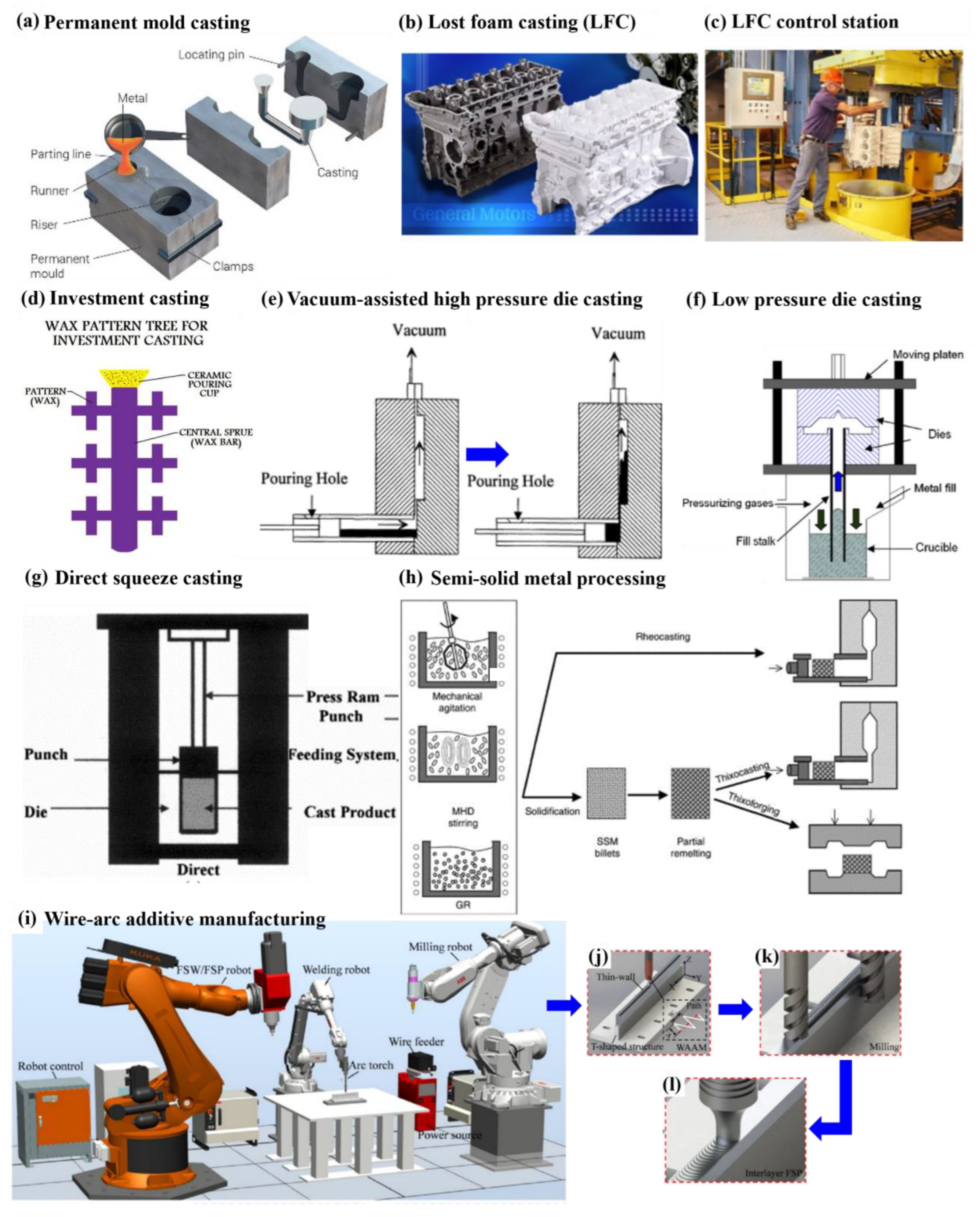
Permanent-Mold Casting

Permanent-mold castings (PMC) are distinguished from other methods based on mold materials, such as iron, steel, stainless steel (Figure 3a), etc., which result in a better surface finish than sand castings [63]. Another variety of PMC used for automotive castings of Al-Si alloy cylinder heads and engine blocks is semi-permanent molding (SPM). This process involves some sections of the castings made with steel, which require a critical microstructure for enhanced mechanical properties. The rest of the core assembly is made from sand, hence the term ‘semi’ [53]. PMC mold temperatures are controlled by cooling channels jacketed around the mold. Venting and proper moisture removal of the mold has to be maintained in the case that the mold is non-porous in nature. Although more time consuming than other advanced casting processes, PMC is currently used in laboratory-grade Al-Si casting research. Elhadari et al. [64] studied the properties of a PMCast Al-Si-Cu alloy with Ti, Zr, and V additions, made with an ASTM B108 steel mold. Mori et al. [65] used PMC with a steel mold preheated to 250 ± 2 °C to cast an Al-7%Si-0.3%Mg-Zr alloy. Tenkamp et al. [66] used the PMC steel mold (preheated to 450 °C) to cast an EN AC-AlSi7Mg0.3 alloy, along with the addition of an AlTi5B1 grain refiner and Sr as a modifier.

Lost Foam Casting

Lost foam casting (LFC), also known as evaporative pattern casting, uses a polymer pattern made within an unbounded sand mold, which evaporates when the melt is poured. Generally, polystyrene foams (97.5% air and 2.5% polystyrene) are used to make the patterns. Figure 3b,c depict the process of Al engine block (gray-colored) casting using the LFC method. LFC obtained public recognition by General Motors in the mid-1980s, after ~20 years since its invention. Various advantages include fabrication of complex castings with multiple cores and dimensional accuracy, an excellent surface finish without draft, and no parting lines to form any flash. However, lower temperature and melt velocities near the casting top leads to increased defect severity in LFC products [53]. Several advancements have been made, such as vacuum-assisted LFC, which further enables the application of this process in industries.
Santos et al. [67] fabricated an A319 alloy using LFC, which resulted in a coarse microstructure with a higher content of shrinkage defects. This was attributed to the very slow cooling rate of the process. Dezecot et al. [68] used LFC to cast an Al-7%Si-3%Cu-Mg alloy to study the loss of mechanical properties in relation to the shrinkage cavities present in the material. Khoukhi et al. [56] compared the efficiency of the LFC process with gravity casting for the mechanical properties of Al-7%Si-0.5%Cu-0.3%Mg and Al-7%Si-0.3%Mg alloys. The LFC process showed 0.28% porosity in comparison to the gravity cast alloy with 0.03% porosity. This further demands significant research to be able to compete with other casting processes. AM can be a big boon for making such patterns more precisely, and this is further discussed in later sections.

Investment Casting

The investment casting (IC) process has been around for 5000 years and is also known as the lost-wax process [69]. First, a mold gives the required shape with all the risers and gating system on a wax pattern. Figure 3d shows a generic design of the molded wax pattern tree for the IC process [70]. This pattern is coated with a wet ceramic slurry consisting of silica, zircon, aluminum silicates, and alumina. After a thick coating of the ceramic is formed, dewaxing the pattern leaves behind the required ceramic mold, called the investment. Proper dewaxing heating rate and temperature are set to prevent any cracks on the ceramic mold (due to the difference in the coefficients of thermal expansion between wax and ceramic). The ceramic mold is gravity-poured with the liquid alloy melt and allowed to solidify. The ceramic mold is removed using controlled hammering or vibration.
The IC process ensures thinner wall castings with the production of a structure with fine grains and no porosity. Due to increased labor costs and long cycle times, the IC process has not been well established in the automotive industries for Al-Si alloys. Such processes have become a huge popular choice in aeronautical industries where surface finish and stringent structure protocols are given priority over labor and costs [69]. Siaminwe and Clegg [71] studied processing variables, such as pouring temperature, cooling rate, ceramic foam filtration, and chemical modification, of the Al-Si-Mg alloy using IC. Dezecot and Brochu [72] studied the high-cycle fatigue properties of an A357 structural alloy fabricated through gravity pouring for IC. Schmahl et al. [73] fabricated A356.0 alloy structural foams using a modified IC method. Other than the gravity pouring of the liquid melt into the investment mold, newer techniques combine the IC process with pressure die-casting, similar to the studies by Barbosa and Puga [74] and Lim et al. [75].

3.1.2. High-Pressure Die-Casting

Die-casting has been around since the mid-1800s, when the first casting printing machine was operated manually. High-pressure die-casting (HPDC) developed gradually, and by early 1900s, Sn and Pb were cast using this method. The production initially declined when the Zn and Al market grew, but now HPDC is the most commonly used casting process in the Al industry (80% of all Al castings in North America) [29]. HPDC produces efficient, near-net-shaped products with higher productivity and higher volume of manufacturing than conventional gravity castings. The working principle involves the injection of molten metal into the die at high velocities, enabled by a hydraulic shot system, which is primarily done against gravity pressure. This process is, in general, more complex than a variety of gravity casting processes seen in the earlier section, using die cooling circuits, controlled filling characteristics, high-pressure equipment, etc. The most critical stage in the HPDC process is during the injection phase, where three different stages of the solidification process take place as follows: (i) slow shot of liquid metal; (ii) liquid metal pushed into the die cavity; and (iii) intensification of the semi-solid melt under incremental pressure to reduce internal shrinkage porosities. Despite such feats, the HPDC parts still suffer from porosities due to inevitable air entrapment during the turbulent flow of the metal.
Advancements in the HPDC process include the addition of vacuum pressure to extract the extra entrapped air that leads to the porosity and poor mechanical properties of the components. Figure 3e shows a simplified schematic of the vacuum-assisted HPDC (VA-HPDC) process [76], where the vacuum pressure can range from 60–3000 mbar. This ensures no remaining gas within the melt after solidification, which enables stable solution-treated products. Wang et al. [77] and Lumley et al. [78,79,80,81] observed the presence of uncontrolled porosities upon solution treating Al-Si-Cu and Al-Si-Mg alloys in different studies using a cold chamber HPDC machine with a shot sleeve. The use of VA-HPDC led to the production of large thin-walled Al-Si castings, which enabled the purpose of lightweighting, as a large number of parts were reduced in an assembly [82]. The Tesla Model Y, “body + battery” compartment is one of the largest “giga-press” HPDC components produced to date [83]. A higher degree of vacuum (<60 mbar) castings (known as HVDC) has been developed in recent studies [2], which improves the weldability and heat treatability of the castings. Rheinfelden GmbH [40] has recently developed several Al-Si-based cast alloys, namely Silafont®-36, Silafont®-38, Castasil®-21, Castasil®-37, Thermodur®-73, and Castaman®-35, which are state-of-the-art HPDC alloys with higher heat treatability and weldability, by adjusting the Fe content below 0.15 wt.%. Casarotto et al. [84] summarized that the best suited HPDC alloy for body structure is Castasil®-37, whereas Silafont®-36 is more suitable for applications in the suspension area with a higher yield strength requirement. A recent study showed enhanced heterogeneous microstructures in a VA-HPDC cast Silafont®-36 alloy, which showed an improved Young’s modulus, higher tensile strength, sufficient ductility, and higher low-cycle fatigue resistance directly in the as-cast state [85,86,87].

3.1.3. Low-Pressure Die-Casting

The pow-pressure die-casting (LPDC) process involves pressure levels lower than the HPDC process, which are generated by the hydraulic action of the molten metal. Figure 3f shows the schematic operations of the process [88]. The dry gas pressure to push the molten metal from the pressurized crucible is about 0.6–0.8 bar. This raises the liquid into the sand or permanent-mold cavity. Due to the steady and laminar flow of liquid metal into the intricate part of the mold cavity, castings with virtually no gas porosities can be made, which could lead to better mechanical properties than the HPDC process. Several advancements, such as the vacuum riser-less LPDC and counter-pressure casting, have been developed for industrial purposes. The use of vacuum ahead of melt filling the cavity helps the components to obtain minimized oxide formation and hydrogen absorption [89]. A constant counter-pressure of 0.3–1 bar leads the molten metal to rise into the cavity, where a high pressure up to 6 bar is applied to ensure proper feeding and to maintain solidification pressure [90]. This enables LPDC to produce high-integrity automotive parts, such as the steering knuckles, subframes, wheels, cross-members, structural brackets, and chassis.
A356 alloys have been most commonly used in LPDC automotive wheels by several researcher, who showed the cost effectiveness of the process to produce high-quality wheels with proper design requirements [91,92,93,94,95,96]. An additional modification by applying local squeeze to the LPDC process was implemented to improve the quality of cast wheels by Huang et al. [97]. Comparative studies between LPDC and other casting types, such as casting–forging, gravity, investment, and lost foam casting, by Lee et al. [98] and Jiang et al. [99] showed that LPDC alloys have higher brittle fracture tendency, where cracks tend to initiate at the eutectic Si particles and cut through the shrinkage pores. Park et al. [100] showed higher strength and lower ductility of LPDC A356 alloy than its rheocast counterpart.

3.1.4. Squeeze Casting

The squeeze casting (SQC) process dates back to the late 1900s, when it was developed to find a solution for the problem of gas and shrinkage porosities in the case of gravity casting and HPDC processes. The application of pressure until complete solidification of the liquid melt in the mold cavity is the primary functionality of this process. SQC products have high integrity, with enhanced wear resistance and improved heat-treatability [2]. Some of the prime SQC Al-Si alloy products include control arms, crankshaft hubs, air-conditioning compressor, steering column components, etc. [101]. SQC can be classified into direct and indirect routes. Figure 3g shows the schematic for direct SQC wherein the pressure is directly applied on the melt via an upper die [102]. This process is more similar to the forging technique, which happens during solidification. Indirect SQC has an extra gating system, through which pressure is transmitted onto the melt. These processes lead to a reduction in shrinkage porosities, using minimal superheat and intensive pressurized solidification.
Industrial SQC of A356 alloys at a pressure of 80–100 MPa leads to a significant increase in nucleation rate, making the grains finer [2]. Recent modifications of SQC include ultrasonic-assisted SQC [103], local squeeze with LPDC [97], and SQC with hot extrusion for wrought Al alloys [104]. Lee et al. [98], studied the SQC process for A356 alloys, which showed enhanced ductility with a refined and densified microstructure. Li et al. [105] studied the SQC of hypereutectic Al-Si alloys with a squeezing pressure of over 600 MPa, maintained for 30 s. The alloys showed a decrease in the size of α-Al dendrites with increasing pressure. Coarse and brittle Si particles converted into fine eutectic Si particles, which led to improvements in all monotonic properties. Although there has not been an industrial stronghold of the SQC process since its development (~20 years ago), indirect SQC is, in many ways, like the HPDC process. SQC processes are now being used for the fabrication of metal matrix composites (MMCs), as shown in a study by Shabani et al. [106].

3.2. Semi-Solid Metal Processing

Semi-solid metal (SSM) casting consists of a variety of solidification processes that work on the die-casting principle of injecting partially solidified alloys into the die cavity to form a near-net-shaped component [107,108,109]. Some metallic alloys behave as a thixotropic medium or a non-Newtonian fluid, which prevents turbulent flow of the semi-solid metal, thereby reducing entrapped air or oxide formation [2]. Figure 3h shows the schematic of the three most commonly used SSM casting methods, namely rheocasting, thixocasting, and thixoforging [2,110]. The slurry before being cast into the final component undergoes several treatments in the liquid state. Ultrasonic stirring, or magnetohydrodynamic (MHD) stirring or mechanical agitation, ensures non-dendritic solidification of the Al phase, which leads to better refined, globular, and equiaxed grains. The dendritic structure is totally broken due to several mechanisms mentioned earlier, one of which states that the dendrite arms bend plastically upon stirring, leading to large misorientations into the arms, forming dislocations. These dislocations at high temperatures detach themselves from the parent branch (higher kinetic energy) and form a “rosette”-like structure [111].
Rheocasting is a slurry-on-demand process that starts by cooling the melt into a thixotropic slurry, which is separated in a two-phase region by thermodynamic adjustments. The slurry is then pushed into the die cavity for final casting. This is highly economical as no billet formation is required as it is in in thixocasting or thixoforging. A356 alloys have been one of the most studied rheocast alloys with globular microstructures and improved mechanical properties in comparison to its conventional casting counterparts [112,113,114,115]. Lü et al. [116] studied A356 alloys cast using the rheo-squeeze casting process (pressure varied from 25–100 MPa), via indirect ultrasonic vibrations.
Thixocasting molds the component inside a die, whereas thixoforging works the partially remelted billet in a closed die-forging chamber. Advantages of such processes include the component being almost free from gas porosities [111]. Compocasting of Al-Si alloys [106] is another simple form of SSM casting, where the slurry is electromagnetically stirred and cast into a permanent steel mold with the application of 50 kg of weight. Brochu et al. [30] reported that A357-SSM cast alloys have 10% elongation, which is two times higher than that of A357-T6 permanent-mold cast alloys. Al-Si alloys after the SSM process can be heat-treated to peak-aging conditions with adequate ductility. The study also showed higher fatigue resistance of SSM-A357 alloys compared to gravity or sand casting methods.

3.3. Additive Manufacturing

Metal additive manufacturing (AM), or 3D printing, is a recent technological development in the fabrication of components from powders or wires as feedstock. The input materials are melted via arc, laser, or electron beam, and the molten pool is deposited layer-by-layer on a substrate to build the final product as designed in the form of 3D-computer-aided design models. Recent developments by Chen et al. [117] showed the combination of semi-solid, thixotropic slurry injection as feedstock to enhance the lightweight AM sector. Although AM has certain benefits over casting, the technology is still associated with some processing defects, such as the lack of fusion pores, cracks, impurities, poor surface finish, etc. [118]. Some studies have shown that AM Al-Si-Mg alloys have higher static strength due to the presence of a finer microstructure, formed by the rapid solidification process [119], and the presence of pores did not affect stiffness or yield strength. However, a significant (~40–50%) decrease in cyclic properties was observed [120]. Thus, the optimization of AM processing parameters needs to be further studied.
AM processes are divided into three broad categories as follows: (i) powder bed systems; (ii) powder feed systems; and (iii) wire feed systems. Powder bed systems are further classified based on the energy beam required to melt and deposit powder particles, i.e., laser or electron beam. If the process uses laser, then laser powder bed fusion (L-PBF) is required [121,122]; otherwise, electron beam-powder bed fusion (E-PBF) [123]. An inert gas atmosphere (N2 or Ar gas) is required for both processes to prevent oxidation during deposition. For E-PBF, a vacuum degree of <10−4 Pa is essential to avoid electron charging and to enhance heat conduction [123]. L-PBF is commonly referred to as the selective laser melting (SLM) process, which produces alloys with anisotropic, cellular microstructures and controlled relative density [124,125].
Powder feed systems or laser direct energy deposition (L-DED) use nozzles to feed powders on to the substrate [25]. This process has a greater advantage over L-PBF in relation to the higher volume of production at a higher built rate. The wire feed system, also known as wire-arc additive manufacturing (WAAM), is a process that directly uses wires as feedstock rather than powders [126]. The energy source for WAAM can either be laser, electron beam, or plasma arc. Although the volume of production is relatively high compared to PBF and DED techniques, WAAM products require ample post-processing for enhanced alloy properties. Figure 3i–l shows the setup with multiple robotic arms for automated WAAM of AA4043 (Al-5%Si) alloys, with immediate post-processing techniques of milling (to make the rough surface flat) and friction stir processing (FSP) [127]. Al alloys fabricated through AM have highly been confined to certain group, such as Al-10%Si-Mg and Al-12%Si alloys, due to their favorable processibility and weldability [128,129]. These alloys with smaller freezing ranges help to minimize the hot cracking tendency during printing [130]. However, recent studies on AM Al-Si alloys have shown unpredictable cyclic properties due to the presence of pores and defects [124,125,131]. As an additional benefit, 3D printing has found another application in the foundry industries of metal casting. Intricate patterns for sand casting or thin-walled wax patterns (for lost foam or investment castings) are manufactured by AM, which reduces pattern development time and improves design precision and complexity [132].
Figure 3. (a) Schematic diagram for gravity die-casting using a permanent mold [63]. (b) Lost foam pattern with Al engine block casting and (c) lost foam control station [2]. (d) Wax pattern tree for investment casting [70]. Schematic of (e) vacuum-assisted high-pressure die-casting [76], and (f) typical anti-gravity low-pressure die-casting arrangement [88]. (g) Schematic of direct squeeze casting [102]. (h) Schematic illustration of different types of semi-solid metal (SSM) casting, namely rheocasting, thixocasting, and thixoforging (MHD: magnetohydrodynamic; GR: grain refinement) [2]. (i) Schematic diagram of WAAM robots along with (j) WAAM processing, (k) milling processing, and (l) interlayer FSP deformation for Al-Si alloys [127]. Reproduced with permission from Elsevier and open-access websites.
Metals 13 00609 g003

3.4. Recycling Al-Si Alloys (Secondary Al Alloys)

Al alloys have a high recyclability, with high recovery rates and usage of a small fraction of energy, i.e., within 5% of the total energy consumed to extract raw Al from bauxite ores [2]. These have helped to curb the carbon footprint and GHG emissions by increasing the energy efficiency and reducing the usage of natural gas to produce primary metals. A major concern for the Al scrap and recycling industry is the level of impurities after recycling. Secondary Al-Si alloys have certain amounts of Fe, which leads to the formation of intermetallics, such as Al15(Fe,Mn)3Si2, β-Al5FeSi, deteriorate the structural properties of the alloy. Hence, these alloys are currently being used for non-structural applications. The addition of Mn and Sr, which decrease the chance of Fe being present in the first generation of Al-Si alloys, have resulted in suitable secondary alloys [133,134]. However, their production is currently limited in industries.
Cinkilic et al. [135] proposed an Fe/Mn ratio CALPHAD-based model to manipulate the alloying content in Al-Si alloys for a variety of castings, ranging from gravity casting to HPDC at various cooling rates. This ensures another generation of Al-Si alloys with higher reusability after recovery by preventing the formation of Fe-rich intermetallics. Becker et al. [136] studied the secondary Al-7%Si-Fe-Mn alloy by varying the contents of Fe and Mn, first thermodynamically and then experimentally, with the purpose of eliminating the harmful β-Fe phase. The addition of Ni to remove the β-Fe phase was studied by Basak et al. [137] on different secondary Al-Si-Fe alloys with 6%, 9%, and 12% Si. Several other studies involved the sequence of microstructural phase formation in secondary alloys with the main intention of removing Fe-based impurities at a lower cost [138,139,140]. These alloys are also coined ‘green alloys’ as they are produced from scrap at a lower cost with lower energy consumption and they help environmental sustainability.

3.5. Designated Heat Treatment for Al-Si Alloys

Heat treatment (HT) is an important step after the casting or fabrication of an Al-Si alloy, which cements the mechanical properties and gives dimensional stability to the alloys. HT carried out at different stages after casting/printing ensures that the product homogenously maintains certain properties throughout its service time. HT controls the overall structural aspect of the castings by modifying the microstructures due to the application of heating and cooling cycles. Generally, HT is carried out in three stages as follows: (i) high-temperature treatment; (ii) quenching to a lower designated temperature; and then (iii) lower temperature treatment. The first stage is known as solutionizing, or solution heat treatment (SHT), and lower-temperature heating is termed aging. Table 2 summarizes the basic heat treatment types used for cast and wrought Al alloys, where all the methods have different combinations of the aforementioned stages [141].
Industrial usage of T4, T5, T6, and T7 conditions for Al-Si alloy castings is very common. Except T5, all the other conditions undergo SHT, which completely alters the microstructure of the alloy, leading to a large range of property changes from the as-cast version. SHT leads to the dissolution of different alloying elements and intermetallics formed during casting into the matrix, leading to the formation of a supersaturated solid solution. Upon quenching these elements are locked within the FCC Al matrix, thereby increasing the matrix strength. The aging step further leads to the precipitation of excess elements on the matrix, which further helps in precipitation strengthening via dislocation pinning. Although some castings show improvement in their mechanical properties after HT, HPDC or LPDC cast specimens result in blistering from the excess air entrapped within the components [81]. Industries must consider different factors, such as the casting process parameters and cost effectiveness, before setting up accurate HT designation for an Al-Si casting.

4. Microstructures

4.1. Binary Al-Si Alloy Systems

Al-Si alloys are better understood with the help of a binary Al-Si equilibrium phase diagram, which can be seen in [142]. The eutectic reaction (Liquid (L) → α-Al + Si) occurs at a temperature of 577 °C with 12.6 wt.% Si. Typical as-cast microstructures of hypoeutectic (<12.6% Si), eutectic, and hypereutectic (>12.6% Si) alloys can be seen in [142]. The primary α-Al (with ~1.65% dissolved Si at eutectic temperature) is solidified in the form of non-faceted dendrites with a eutectic Al-Si structure present in-between them. Al being of an FCC crystal structure and Si being of diamond cubic crystal structure does not form any intermetallic compounds. The eutectic structure varies in morphology, size, and distribution, based on the chemical composition and the cooling rate during alloy making. Hypereutectic alloys contain primary Si polyhedral crystals, unlike hypoeutectic alloys. Primary Al dendrites are ductile, while primary Si is extremely brittle, which reduces the applicability of hypereutectic alloys in automotive applications during static/cyclic loading and extreme wear conditions [143]. It has been observed that cleavage fracture is the main brittle cracking mode in Si due to the small surface energy [142]. Later sections discuss, in detail, Si modifications using chemical modifiers that significantly affect the mechanical behavior of Al-Si alloys. Commercial and engineering Al-Si alloys are not limited to Si as the only alloying element. To impart proper strength and fracture resistance, several other elements are added to an optimized content during alloy development.

4.1.1. Major Alloying Elements

Manufacturing Al-Si alloys includes the addition of alloying elements that can be classified into several groups. Mg, Cu, Ni, and Mn elements are considered to be the major alloying elements, while Sr, Ti, P, B, other transition metals, and rare-earth elements are considered minor additions. Major alloying elements provide much-needed solid solution strengthening and precipitate strengthening to the alloy. Minor alloying elements enhance the alloys’ mechanical integrity and overall wear, soundness, and porosity [144]. Impurities such as Fe, Pb, Sb, and Sn are major concerns for industries as these are responsible for the poor physical, mechanical, and service characteristics of various applications [143,145,146,147]. Table 3 summarizes the average composition of industrially used structural Al-Si alloys manufactured through different routes with different heat-treatment conditions [2,40,56,57,58,61,62,64,65,66,72,77,80,81,82,87,119,127,148,149,150,151,152]. This review article briefly covers some of the important characteristics and recent advancements of the major and minor alloying elements in these Al-Si alloys.
Si is the most prominent addition to Al. It imparts castability and fluidity and reduces shrinkage in an Al-Si alloy. It forms the Al-Si eutectic structure in alloys and exists in the primary form of hypereutectic alloys. Although only 1.65% of Si is soluble in Al at eutectic temperature, it does not yield adequate solid solution strengthening of the Al matrix [153,154]. Near-eutectic and eutectic alloys also show the presence of a skewed couple zone due to non-equilibrium solidification, which results in coarser, polyhedral primary Si particles [155]. These crystals need to be removed by further chemical modifications and solution treatment to non-harmful geometries [156]. Al-Si eutectic structures in hypo- or eutectic alloys take the shape of long, acicular, needle-like particles, which lead to improved mechanical properties in Al-Si alloys. However, Si particles with a higher aspect ratio (length-to-diameter ratio) lead to poor ductility due to a higher stress concentration. Further sections discuss Si modifications into fibrous, coralloid, or rounded structures, which lead to improved elongation.
Automotive-grade Al-Si alloys often contain Mg as an important alloying addition to the system. Mg addition leads to higher solid solution strengthening in Al and the formation of several MgxSiy-based precipitates (Mg2Si being the most common) upon T5 or T6 heat treatment, which provide additional strengthening. Mg is also known for reducing feed demand by shortening the solidification range, leading to lower levels of microshrinkage and greater alloy stability [157]. Pressure die-castings often adjust the Mg content within ~0.1–0.5% to meet the component requirements of strength and ductility [40]. Cu addition leads to improved cast and high-temperature strength of Al-Si alloys, but this reduces ductility. The ability of Cu to form Al2Cu precipitates upon heat treatment makes it a major alloying addition [156,158]. Cu-rich phases take several morphologies like that of fine and blocky Al-Cu-Si-Mg compounds, where the shape depends upon the chemical composition, solidification rate, and heat-treatment conditions [156]. Optimal Cu additions ranging between 2–4 wt.% provide proper solid solution strengthening to the Al matrix. Aerospace Al-Si alloys do not prefer Cu, as it extends the overall freezing range, leading to excess interdendritic feed demand, which leads to high porosities if not curbed [157]. Ni acts as an element which improves the high-temperature strength of Al-Si alloys such as A390 in the range of 250–375 °C. However, at room temperature, the presence of Ni reduces elongation due to the formation of brittle intermetallics (Al3Ni) [29]. Like Cu-based phases, Al3Ni particles can strengthen the alloy. However, when the amount of Ni exceeds 4 wt.%, casting soundness is reduced, and the alloy is susceptible to cracking [159]. Zn addition within 1–4 wt.% does not affect the ductility of Al-Si alloys and slightly improves the tensile properties after T5 or T6 heat treatments. A study by Robles Hernandez et al. [143] showed that alloys with a Zn amount of >15% can promote a high rate of corrosion. Minor alloying elements such as Sr, Na, Sc, transition metals, rare-earth elements, etc., are added to alloys based on the design requirements of the components. Sr, Na, and Sc act as Si phase modifiers and grain-refining agents, which have a greater use in automotive industries for reliable Al-Si alloys. However, the limit of such elements is capped below <1% as they can nucleate other defects in the alloys, such as porosities and shrinkage [20,160,161,162].

4.1.2. Impurities

Fe is the prime impurity in Al-Si cast alloys due to the formation of Al-Fe brittle intermetallic phases [147,163,164]. It is generally present in scraps and secondary Al alloys which have a prior history in engine blocks or cylinder heads alongside cast iron liners, or it gets added into the melt during casting. Al5FeSi (β-phase) shows a plate- or needle-like morphology which acts as a stress concentrator in Al-Si castings, reducing integrity and incurring machining expenses. Researchers have been trying to reduce the content of Fe in alloys below <0.2%; however, it’s an ever-growing challenge for recycled alloys where the limit is clipped at 1%.
Mn is considered a savior of Al-Si cast alloys with protection from the detrimental effect of Fe-based phases and intermetallics. The addition of Mn reduces the much-needed sticking tendency of the melt during die-casting and removes Fe from castings [87]. Although it has some beneficial effects during the fabrication process, the presence of Mn is considered an impurity due to the excessive formation of dendritic, blocky, or Chinese script intermetallics of the Al-Fe-Mn-Si system, such as Al9Fe0.84Mn2.16Si [87,148], Al8(Fe,Mn)2Si [165], Al15(Fe,Mn,Cr,V)3Si2 [65,157], etc.

4.2. Principles of Solidification

Metal manufacturing routes, such as casting or additive manufacturing, play an important role in affecting the microstructures of Al-Si alloys. The size, shape, distribution, and volume fraction of primary dendrites, Al-Si eutectic, intermetallics, and precipitates all depend upon factors such as cooling rate, chemical alteration, melt temperature and pressure, feed rate, etc. Although these alloys are simplistically regarded as Al-Si binary systems, the presence of alloying elements, such as Cu, Mg, Fe, etc., describes the system more accurately with ternary or quaternary phase diagrams [166]. Some of these essential factors are briefly discussed with recent modifications that lead to advanced alloy microstructures for Al-Si alloys in this section.

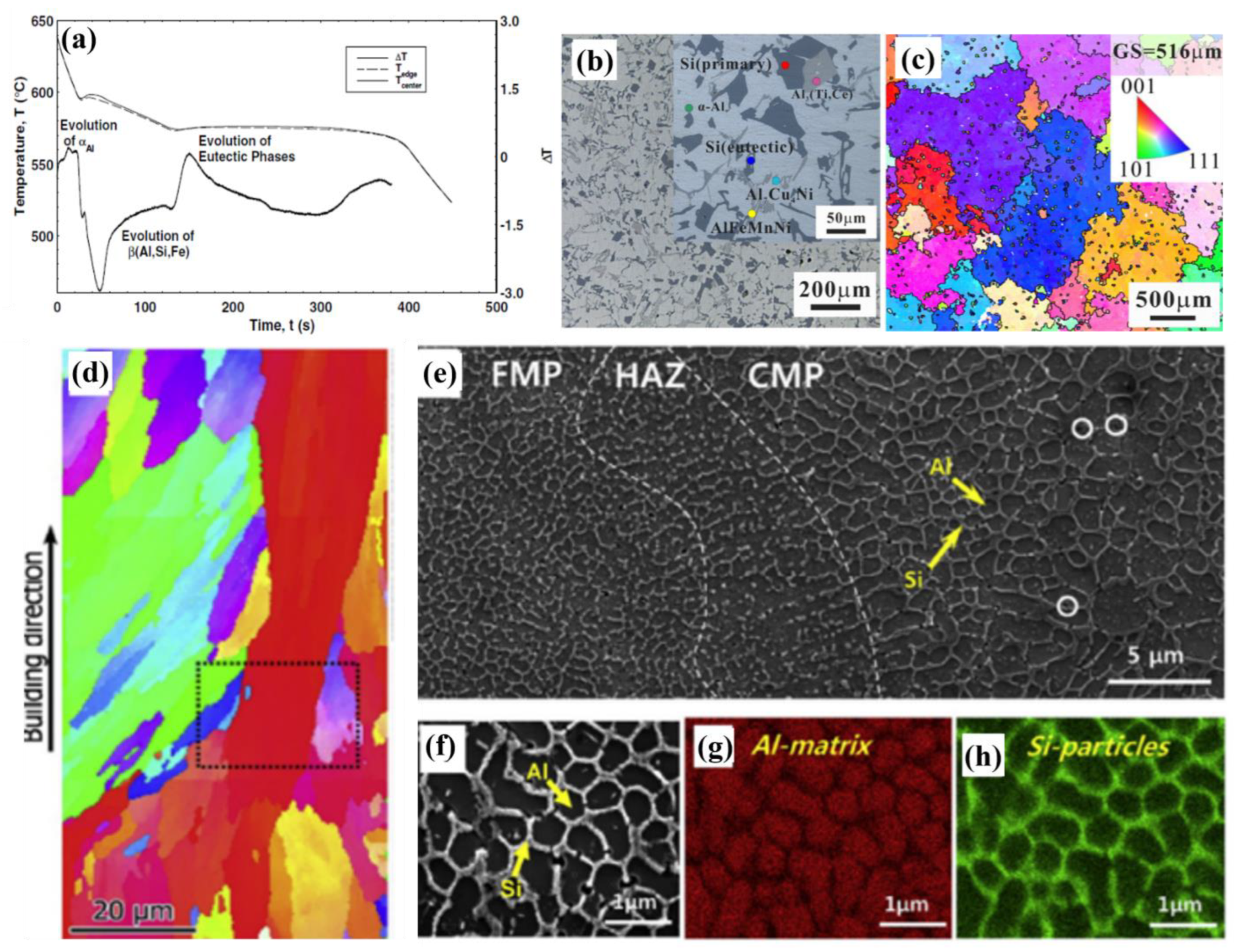
4.2.1. Solidification Sequence

Al-Si alloys containing major and minor alloying elements start with solidification of the primary α solid solution of Al. The addition of inoculants, such as B or TiB2, controls the process of nucleation of α-Al dendrites at liquidus temperature [157]. The solidification process for Al-Si alloys reported by Shankar et al. [166] includes three steps, where the first step begins with the nucleation and growth of Al dendrites. In the presence of Fe, Mn, Mg, or other alloying elements, small secondary/intermetallic phases nucleate at the interface of liquid and α-Al. Upon reaching eutectic temperature, eutectic Si nucleates, along with eutectic Al. Furthermore, nucleation and growth arrest the process, forming the as-cast microstructure. Thermal analysis data collected during the solidification process, as shown in Figure 4a for an Al-Si-Fe alloy [166], show imminent proof of the solidification sequence. Each peak or drop in the first derivative of temperature (ΔT) corresponds to the formation of a phase and determines the liquidus, solvus, and solidus temperatures of the alloy. Such plots also help to visualize the dendrite coherency point (DCP), which is the point of contact between different α-Al crystals. Apart from the formation of α-Al and the eutectic structure, and based on the chemical composition of the alloy, different intermetallics and precipitates nucleate, grow, and arrest at different temperatures/times on the plots. The formation mechanism of platelet eutectic Si crystals, where the diffusion of Si and Al interchangeably takes place in the primary α-Al and eutectic Si, respectively, and was studied by the authors of [157]. This is known as the twin-plane reentrant-edge (TPRE) growth mechanism [157,167,168,169]. Researchers have developed newer methods which alter the branching mechanism at the twin boundaries, leading to fibrous Si particles in the eutectic [169,170]. Secondary dendritic arm spacing (SDAS, λ2) is characterized to understand the coarsening and orthogonality of secondary dendrites and is an important parameter for studying the mechanical properties of cast alloys. The prominent effect of such parameters is discussed more in the section on mechanical properties.

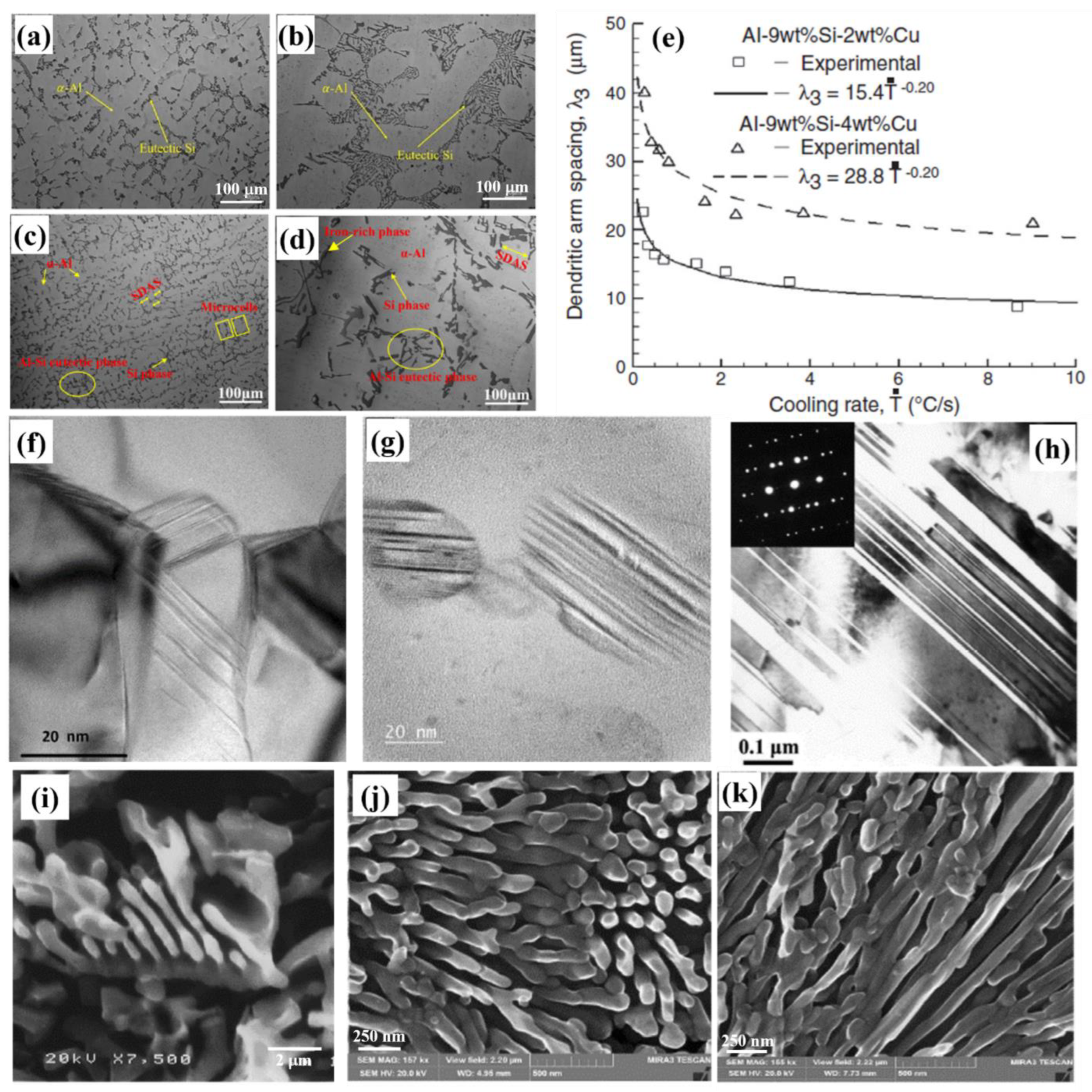
4.2.2. Microstructural Evolution

Solidification mechanisms in Al-Si alloys lead to the attainment of various types of microstructures for researchers to understand and thus for better alloy design. Automotive and aerospace components should abide by certain features in the alloy microstructure to be operable. Excess presence of brittle phases might improve strength but would lead to severe and unexpected failure under static/cyclic loading. β-Fe intermetallics show poor interfacial bonding with the matrix, which lead to deleterious effects on the ductility of the alloy. However, α-Fe intermetallic phases that take various forms and stoichiometries, such as α-Al8Fe2Si, α-Al12Fe3Si2, α-Al17(Fe,Mn,Cr)3Si2, and α-Al15(Fe,Mn,Cr)3Si2, show higher interfacial bonding and lower stress concentrations [171,172]. Volume fraction of the Al-Si eutectic structure in some typical Al-Si alloys can comprise ~40% (A319 and A356 alloys) and even ~100% (A413 alloy). The rest of the microstructure consists of primary α-Al, secondary inclusions, and intermetallics. Figure 4b shows the microstructure of a typical gravity casting Al-12% Si piston alloy, with 3% Cu, 2% Ni, and 1% Mg as the alloying elements [173]. The grain size is ~516 μm, as seen from the electron backscatter diffraction (EBSD) image of the alloy in Figure 4c. Primary α-Al, along with eutectic/primary Si, shows the presence of several intermetallic compounds (including AlCuNi, AlFeMnNi, Al3(Ti,Ce), and β-Al5FeSi phases).
With newer developments in additive manufacturing routes such as L-PBF, classical Al-Si alloy microstructures with primary dendrites and a eutectic structure have been strikingly modified. Alloys with near-eutectic Si composition (10–12 wt.%) are successful for 3D printing due to less solidification cracking [174]. The microstructure of the 3D-printed alloys is made up of large columnar grains (detectable only by EBSD techniques, Figure 4d), stemming from the epitaxial growth along the building direction [175]. The Si particles form a cellular network structure within these grains, which have different sizes and arrangements based on the severity of the melt pools (fine (FMP) or coarse (CMP)) and heat-affected zones (HAZ). Figure 4e–h show the cellular structure in an SLMed Al-10%Si-Mg alloy [176]. Mechanical properties in these alloys are governed by Hall–Petch strengthening due to eutectic boundaries, as well as Orowan effects due to the presence of Si and Mg2Si precipitates [177,178]. Although the development of additive manufacturing routes has been significant, there are many challenges to face when scaling them up to industrial levels for high-strength Al alloys, without susceptibility to cracking and preventing other microstructural artefacts [25,174].
Figure 4. Cooling curve showing the sequence of the phase evolution during solidification for (a) Al−8.5%Si−Fe alloy [166]. (b,c) Optical and EBSD microstructures for gravity cast Al−Si piston alloy, respectively [173]. (d) EBSD−inverse pole figure map showing columnar grains for L−PBF Al−10%Si−Mg alloy [175]. (e,f) Cellular microstructures for SLMed Al−10%Si−Mg alloy with EDS phase analysis showing the elemental distribution of (g) Al and (h) Si [176]. Reproduced with permission from Elsevier.
Metals 13 00609 g004

4.3. Grain Refinement

Grain refinement leads to increased homogeneity, integrity, and quality of Al-Si alloys. Finer dendrites, particles, and eutectic structures improve alloy machinability and tribological characteristics, reduce shrinkage porosities, and improve overall mechanical strength [179,180]. Processing parameters, as mentioned earlier, play a major role in shaping the microstructure of Al-Si alloys, especially the solidification rate. Routes such as L-PBF-printed materials with rapid solidification during the laser scanning process yield extremely fine microstructures and the precipitation of finer strengthening phases [174,181]. Conventional casting processes can control the solidification cooling rate by adjusting the melt and mold temperatures. Ge et al. [61] and Zhou et al. [62] studied the microstructures of precision sand cast A319 alloys at different cooling rates with and without the addition of Sr. The microstructures are shown in Figure 5a–d. Figure 5a,c present a cooling rate of 10 °C/s, demonstrating a fine microstructure, while Figure 5b,d present a cooling rate of 0.1 °C/s, exhibiting a coarse microstructure. These studies used Cu end chills to control the cooling rates. Cast iron chills are also used to extract heat during solidification to increase the cooling rate. The significant reduction in the SDAS (λ2) and grain size of the α-Al dendrites, Al-Si eutectic structures, and intermetallics can be clearly observed for higher cooling rate samples. Apart from SDAS, Figure 5e shows the tertiary dendritic arm spacing (λ3), which decreases exponentially with increasing cooling rate for Al-9%Si-Cu alloys [182]. λ3 controls the extensive distribution of both solutes (micro-segregation) and the intermetallic phase (Al2Cu) throughout the microstructure, and higher Cu content leads to significant thickening in the dendritic spacing. A controlled addition of grain-refining agents, such as Ti and B, to the master alloys leads to the formation of Al3Ti and AlB2 phases, which act as heterogeneous nucleation sites for primary α-Al. Manufacturing routes involving ultrasonic or electromagnetic stirring of the liquid melt, such as rheocasting, thixocasting, etc., induce shear forces that break the newly formed dendrites and phases into finer particles [111].

4.4. Modification of Si Morphology

It is essential to modify the morphology of Si particles which exhibit a detrimental effect on alloy ductility and strength. For example, a needle-like coarse Si particle causes higher localized stress concentration, which nucleates a crack at the Al-Si interface, followed by catastrophic failure of the alloy. Figure 5a,b also show the effect of eutectic Si modification from coarse needle-like platelets to fine and rounded particles by the addition of Sr at ppm levels to the master alloy [61]. In addition to Sr, several other chemical modifiers, such as P, Sc, Na, Sb, lanthanides, etc., have also been studied, which help to remold Si into a more rounded and fibrous structure [183,184,185,186]. Sr has been the preferred modifier for Al-Si alloys for decades for being stable and less reactive [187]. A schematic comparison of cast microstructures for unmodified, Sr-modified, and Na-modified Al-7% Si alloys was presented in [185,186]. Lu et al. [184] studied the modification of Si using a non-metallic, nanostructured chemical called phenyl-TSP (trisilanol phenyl polyhedral silsesquioxane), which was added to the master alloy.
As mentioned in Section 4.2.1, TPRE growth mechanism leads to the formation of flaky Si by multiple twinning. Evidence of such twinning growth is obvious from several studies with TEM observations of Si particles, as shown in Figure 5f–h [188,189]. Impurity-induced twinning and Sr poisoning of the growing ledges in TPRE are considered the major mechanisms for the isotropic growth of Si along multiple directions for modified Al-Si eutectic colonies [184]. Abboud and Mazumder [188] developed nano-sized fibrous eutectic Si particles in Al-Si hypereutectic alloys by laser surface remelting. Post-modification morphologies of eutectic Si particles are shown in Figure 5i for Sc-modified Al-6%Si alloys [190] and Figure 5j,k for laser-remelted Al-20%Si alloy [188]. The selection of modifiers also depends on the ‘fading’ (loss of element due to oxidation with time) of the element. Relatively rapid fading of Na in comparison to Sr leads to its decreased usage [17,191,192,193].
Figure 5. Optical microstructures (OM) of A319 + Sr alloy solidified at a cooling rate of (a) 10 °C/s and (b) 0.1 °C/s [61]. OM of A319 alloy without Sr solidified at a cooling rate of (c) 10 °C/s and (d) 0.1 °C/s [62]. (e) Change in the tertiary dendritic arm spacing (λ3) of Al−9%Si−Cu alloys with cooling rate [182]. Different twin densities observed in eutectic Si particles for (f) Al−20%Si laser−remelted alloy [188], (g) Al−17%Si laser-remelted alloy [188], and (h) Al−11.5%Si−Mg−Cu−Ni + Si3N4 composite [189]. Post−modification morphologies of eutectic Si particles in (i) Al−6%Si−0.4%Sc alloy [190] and (j,k) Al−20%Si laser-remelted alloy [188]. Reproduced with permission from Elsevier, John Wiley and Sons, MDPI, and Springer Nature.
Metals 13 00609 g005

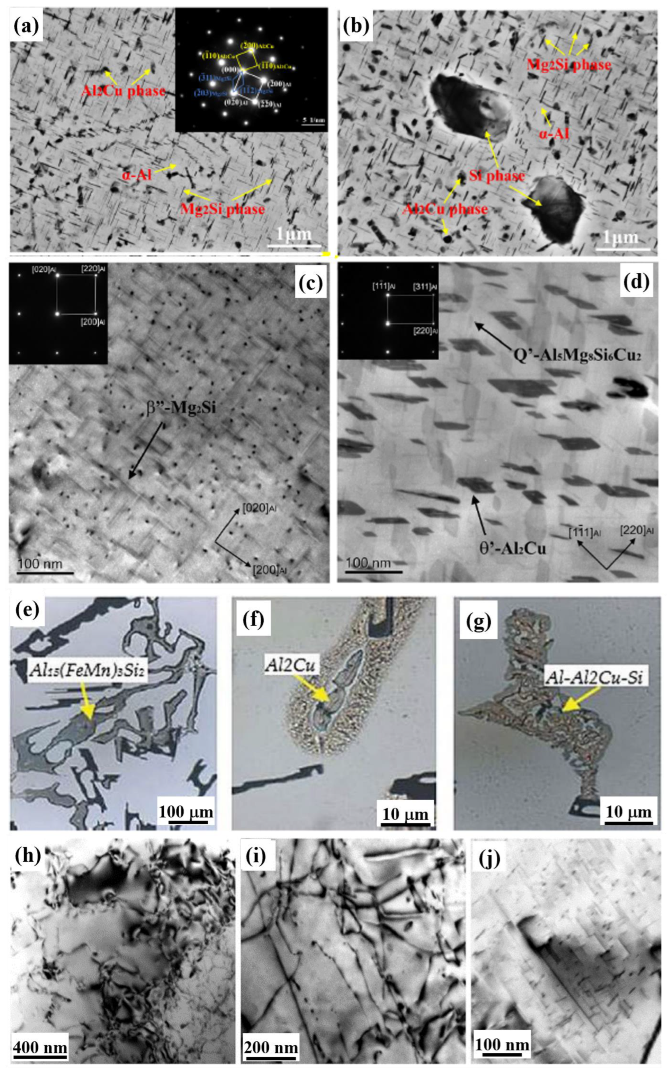
4.5. Precipitation Phenomena in Al-Si Alloys

Castable Al alloys with heat treatability are a major source of lightweighting in automotive powertrains, such as cylinder heads and engine blocks [2]. Al-Si alloys with additions of Cu, Mg, Mn, Ni, Zr, Ti, V, and some rare-earth elements show higher strength and ductility under room temperature and high-temperature operations due to the formation of stable precipitates [194,195,196,197,198,199]. The formation of precipitates depends on the thermodynamics and kinetics of alloy fabrication, heat-treatment sequence, and alloy chemistry. The precipitation sequence during aging can be generalized as:
Supersaturated solid solution (αSSSS) → Formation of GP (Guinier-Preston) zone → Formation
of metastable phase → Formation of equilibrium precipitate phase.
In Al-Si-Cu alloys, the supersaturation of Cu in the Al matrix leads to further instability, which forces Cu atoms to precipitate sequentially as:
αSSSS → GP zones → θ″ → θ′ → θ (Al2Cu) phase.
The incoherent θ (Al2Cu) phase, along with eutectic Si particles, is shown in Figure 6a,b for A319-T6 alloys solidified at different cooling rates of 0.1 °C/s and 10 °C/s, respectively [62]. θ″ and θ′ are metastable phases, which later grow into θ phases. These bright-field transmission electron microscopy (BF-TEM) images also show rod-shaped cylindrical precipitates of Mg2Si, which are formed under controlled precipitation and are distributed homogeneously. Mg content below 0.7 wt.% does not appreciably form sufficient Mg2Si precipitates to give a measurable improvement in mechanical properties [143]. The formation of Mg2Si follows the following sequence [200]:
The atoms of Mg and Si → Formation of co-clusters of Mg and Si → Needle-shaped
β″→ Rod-shaped β ′ → Plate-shaped β (Mg2Si) phase.
Mg2Si can also take the form of the black plate/script phase, which initially nucleates in the form of rod-shaped precipitates along [001]Al and [010]Al axes (as shown in Figure 6c) [65]. The presence of both Cu and Mg in Al-Si alloys results in the formation of Q′-Al5Mg8Si6Cu2 and S-Al2CuMg phases, which can be seen in Figure 6d and Table 4, with a length of 40–50 nm and a thickness of a few nanometers [65,151]. Figure 6e–g show some varying morphologies of Al2Cu and other Fe-based intermetallic precipitates in an Al-9%Si-3%Cu alloy. The three-phase eutectic structure, such as Al-Al2Cu-Si, also occurs in recycled Al-Si alloys [201]. Lumley [81] considered three Al-Si-Mg alloy systems, like that of A356 alloys, made by HPDC using raw materials from scrap metals and subjected to T4 and T6 heat treatment. The observed microstructures of all six types of alloys showed the dispersion of Si within the eutectic structure in the as-cast alloys. After heat treatment, the Si phase fragmented and became spherical, along with the presence of the well-dispersed α-Al15(Mn,Fe)3Si2 phase. Each alloy contained the more innocuous polyhedral Al15(Mn,Fe)3Si2 phase, and none of the deleterious needle-like Al5FeSi phase. Roy et al. [202,203] studied the microstructural and mechanical properties of a variety of Al alloys (A319 A356 alloys with and without Cu). It was observed that the change in morphology of Si particles due to T6 treatment was effective in reducing the pores and defects that improved the mechanical properties. The π-phase (Al8FeMg3Si6), one of the most common precipitates found in Al-Si alloys, was characterized along with other Fe-bearing intermetallics that are known to be deleterious to the elongation of alloys.
The microstructure of different heat-treatment conditions for Al-12.7%Si-0.7%Mg alloys are shown in Figure 6h–j [150]. The absence of artificial aging in T1 and T4 conditions leads to networks of dislocations being observed under TEM in the α-Al matrix. When peak aging occurs in T6, needle-like Mg2Si particles start to appear. Appropriate aging conditions and chemical composition are essential to obtain homogeneous precipitation. Solution treatment of base alloys at a certain temperature, quenching, and then natural or artificial aging steps are followed to obtain the final precipitates in the matrix. The most important condition for precipitates to form is that the precipitate-forming element should be highly soluble at high temperatures, and with decreasing temperature, its solubility should significantly decrease. Coherency or lattice matching is a big factor that influences the sequence of precipitate formation from the metastable phases to the stable phase. Shearable precipitates can impede the movement of gliding dislocations through a variety of dislocation/particle interaction mechanisms, including those described as interfacial (chemical) strengthening, coherency strengthening, stacking fault strengthening, modulus strengthening, and order strengthening.
Researchers have been studying the effect of precipitation using phase field modelling, which can predict approximate strengthening/strain-hardening mechanisms. Chen et al. [204] developed an integrated precipitation-strengthening/strain-hardening numerical model based on the principles of solidification and solution treatment parameters for predicting tensile properties, such as the strength and elongation of Al-7%Si-Mg alloys. The model overestimated the yield strength by selecting needle-shaped β″ (Mg5Si6) precipitates. The yield strength increased due to increased precipitation strengthening with increasing Mg concentration and higher solutionizing temperature. Recently, Zhang et al. [205] used Kampmann–Wagner (KWN) numerical phase field model to study the integrated mechanism of precipitation strengthening and provide newer design and optimization to the T5 heat treatment process of Al-11%Si-xMg alloys. Due to the growth in artificial intelligence (AI) and computational power, more researchers are trying to predict the precipitation kinetics of alloys without any experimentation. This is growing as a cost-effective measure to design newer alloys with optimized precipitation strengthening.

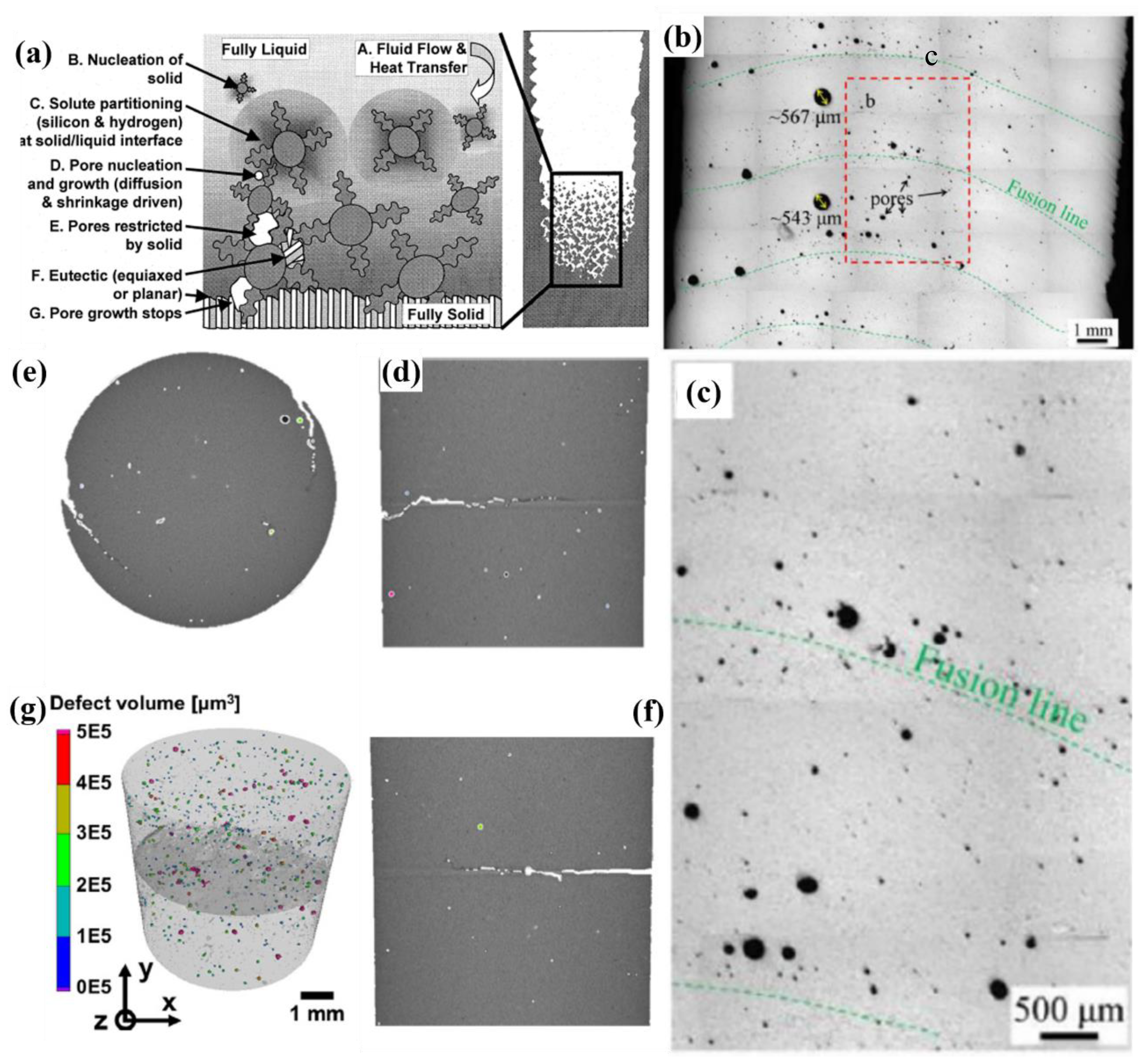
4.6. Porosity and Shrinkage Formation

Porosities in cast and additive-manufactured Al-Si alloys can be classified into either macroporosity or microporosity, which are formed due to the entrapment of gas or shrinkage voids [206]. The heterogeneous nucleation of gas pores in Al alloys is generally due to oxide film or bi-film containing trapped air. Stable pore development depends on the internal pressure of gases such as hydrogen and surface tension at the gas–liquid interface [144]. Shrinkage pores are conceived when regions are poorly fed with liquid metal and are completely cut-off from the source hindered by already-formed solid phases. Figure 7a shows the schematic of different physical processes involved in the formation of micropores for Al-Si cast alloys containing hydrogen [206]. The quality of the manufactured products via casting processes is assessed based on the level of porosity as it leads to low elongation or poor fatigue properties. 3D-printed materials also face a similar issue in terms of incompetent bonding between layers (lack of fusion) and the entrapment of gas during the solidification of each layer, which result in the formation of pores [125,127]. Figure 7b,c show the location of a lack of fusion pores near the fusion boundaries and heterogeneously nucleated pores in the solidified regions for 4043 Al-Si alloys [127]. Haselhuhn et al. [207] studied levels of porosity formation due to altered chemical compositions of hypoeutectic Al-Si alloys using modifiers and grain-refining agents, such as Sr and TiB. The study showed an increase in porosity upon the addition of Sr or TiB to Mg-containing alloys, separately, and a decrease in the presence of all three alloying additions. Newer studies have investigated scale-bridging mechanisms, which lead to controlled fatigue strength of Al-Si alloys using crack-pore deflection. Figure 7d–g show a meso-scale fracture mechanism studied by Awd et al. [125] for SLMed Al-10%Si-Mg alloys, where the plastic energy dissipation of the main crack by the pores results in the deflection of cracks to a new direction, thereby lengthening fatigue life.

5. Static Mechanical Properties

Static mechanical properties such as hardness and Young’s modulus, as well as tensile and compressive behavior, are the principal design parameters for any materials used in a specific application. Table 3 summarizes the major commercial Al-Si alloys from the open literature with their tensile properties of yield strength (YS), ultimate tensile strength (UTS), elongation (%El), and Young’s modulus (E), along with information about their fabrication method, chemical composition, heat-treatment tempers, and testing temperature.

5.1. Elasticity and Hardness

The design of automotive and aerospace components requires materials with higher stiffness or elastic modulus/Young’s modulus. Pure Al and Al alloys have E in the range of 60–70 GPa [208]. From Table 3, it can be seen that the average E for Al-Si alloys is >70 GPa, such as HPDC Al-Si-Cu alloys with 80 GPa [77] and gravity cast A319 alloys with 78 ± 2 GPa [152]. The variation of E in Al-Si alloys has been studied by several researchers. Amirkhanlou and Ji [208] showed that the E value of Al-Si binary alloys increases with increasing Si content, along with decreasing density of the alloy. As seen from any general Al-Si binary phase diagram, the maximum solubility of Si in Al at the eutectic temperature is 1.65 wt.%, and the eutectic fraction of Si in Al is 12.6 wt.%. In hypo- and hyper-eutectic alloys, the stiffness depends upon the morphology and content of Si in the microstructure. When ESi = 162 GPa, the covalent bonding of Si is stronger than the metallic bonding of Al. More Si in the alloy leads to an increased number of Si-Si covalent bonds, thereby resulting in higher E. Dash et al. [86,87] calculated increasing E in as-cast Silafont-36 alloys via the rule of mixtures, using the volume fraction of Si and Al phases. Si in the eutectic occupied ~22% volume fraction, leading to an E of 78–88 GPa, which was corroborated experimentally to by 80 ± 2 GPa. Further SHT of the alloy and increasing testing temperatures led to a decrease in the E value as the detached and spheroidal Si particles had lower bonding strength in comparison with the fibrous/coralloid network of eutectic Si particles [148,209]. The presence of intermetallic phases with higher E can further improve the overall stiffness of an Al-Si alloy [210,211].
Several researchers have reported the hardness of Al-Si alloys, mostly using the microhardness scale of measurements. Lados et al. [212] documented the effect of both modified and unmodified Si content and aging time on the microhardness of the Al matrix for several Al-Si alloys. It was observed that with increasing aging time, the hardness of the Al-Si alloys increased, and the alloy with a higher Si content had higher hardness. In the overaging stage, the hardness began to decrease. The presence of other alloying elements showed a significant effect on matrix strengthening due to the formation of hard intermetallic phases, which act as sources of movement blocking of dislocations. This was studied by Lumley et al. [79] on Al-Si-T7 heat-treated alloys with various contents of Si, Cu, Mn, and Zn, with respect to the aging time. Al-Si alloys with an atomic ratio of Cu:Mg close to 1:1 can be identified as ideal rapid hardening alloys [213]. The presence of Q′ precipitates (Al5Cu2Mg8Si6) within Al grains proves to be advantageous to the work-hardening rate for such alloys [214]. If the solution treatment temperature is low, the peak age hardening of the alloy is lower [78]. Lumley [213] showed the rapid hardening effect of aging temperature and time on the variation of hardness for a particular A380 alloy (Figure 8). The study proved that the lower age-hardening ability was caused by lower Mg content. This was ascertained due to the absence of Mg2Si precipitates in the alloy, which is an important secondary hardening phase in Al-Si-Mg systems. Liu et al. [215] showed that the volume fraction of the precipitates formed and the reduction of interparticle spacing enhanced hardness. Recently, the instrumented hardness measurement, also known as nanoindentation, has emerged to measure the microscale properties of individual phases in multi-phase materials. Table 4 shows the nanohardness of a permanent-mold cast Al-7%Si-0.4%Mg alloy with varying Cu content by Bogdanoff et al. [151]. It can be seen that the increase in the nanohardness of the α-Al matrix takes place with increasing Cu content in the matrix. An increase in Cu content also leads to an increase in area fraction of the Q′ (Al5Cu2Mg8Si6) and θ (Al2Cu) phases, thereby providing adequate secondary hardening.

5.2. Tensile and Compressive Properties

The strength and ductility of Al-Si alloys are controlled by the chemistry of the alloy, solidification rate, phase size, homogeneity, and heat-treatment conditions. Secondary factors or non-inherent factors, such as pores and oxides present during fabrication, also affect these static properties and result in a statistical variation, which makes industrial material selection difficult. Some of these factors have been briefly summarized to understand how the deformation mechanism occurs in Al-Si alloys under static uniaxial loading. It should be noted that common tensile tests of Al-Si alloys follow ASTM E8/E8M standards, with similar studies considered in this summary.

5.2.1. Effect of Si Content

Si particles largely affect the static strength of the Al-Si alloys, similar to their effect on the modulus and hardness. The concentration, morphology, size, and distribution of Si particles have been studied by many researchers to decipher the deformation mechanisms in the alloys. The different characteristic regions of Si content in Al-Si alloys, which would be related to different deformation mechanisms of the alloy, are depicted in [142]. According to this study, the increase in Si content up to eutectic composition leads to a significant increase in tensile strength, with modified or unmodified Si particles. After exceeding 12.6 wt.% of Si, strength in the hypereutectic region starts to decrease. Sr modification benefits the alloy by increasing the yield strength, which makes the material more resistant to dislocation slip. Due to the spheroidization of eutectic Si particles, localized plastic deformation (due to strain incompatibility between Al and Si particles) is delayed [72].
Bernsztejn and Zajmowskij [216] proposed an empirical equation to account for the variation in average stress in the Al-Si alloys as a linear function of the volume fraction of Si is as follows:
σ = σ α V V α + σ Si V V Si = σ α + V V Si σ Si σ α ,
where σα and σSi are the respective stresses for matrix and Si. Although this equation predicts stress values versus volume fraction of Si particles, the influence of the morphology, average particle size, and the distribution of brittle phases are not considered. Better predictions were later provided by the Hall–Petch equation for the flow stress of polycrystalline materials, which considers the dislocation mechanism involving the effect of grain/phase boundaries.

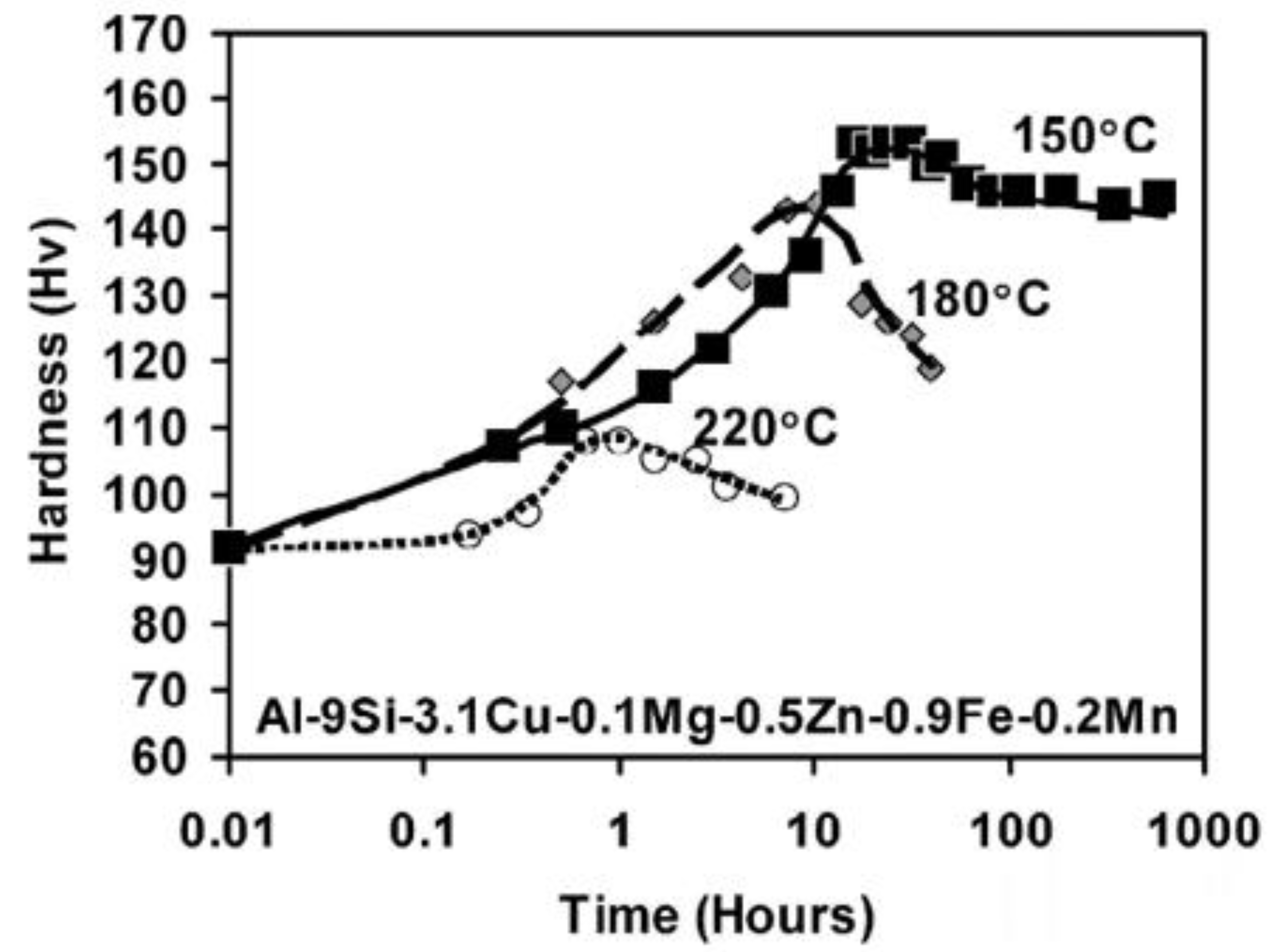
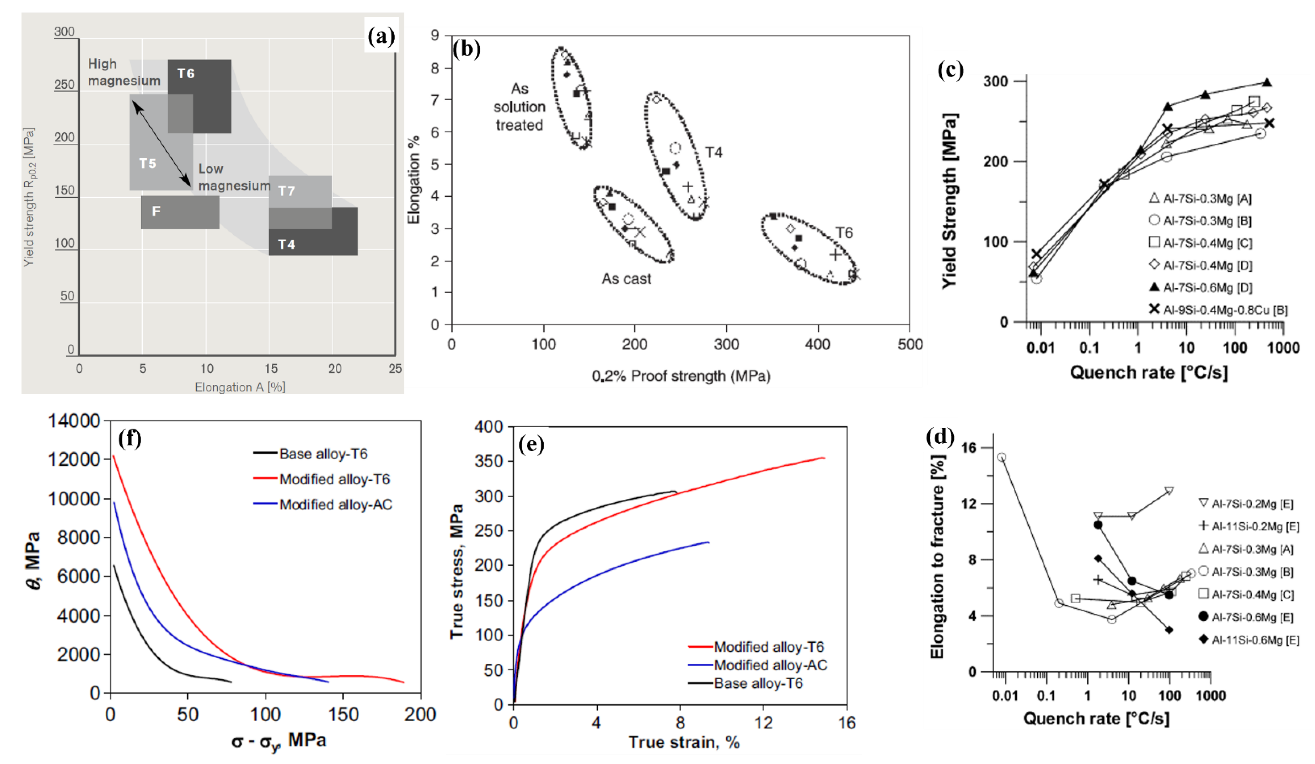
5.2.2. Effect of Heat Treatment

Cast and wrought Al-Si alloys often show improvements in tensile properties after certain heat-treatment cycles, as seen in Section 3.5. Figure 9a shows the effect of different industrial-grade heat-treatment cycles on tensile yield strength and elongation properties of Silafont®-36 (Al-10%Si-Mg) alloys [40]. Peak-aging temper (T6) leads to the highest YS with low ductility, and T4 temper with solutionizing and natural aging shows higher ductility but lower strength when compared to the as-cast (F) state. The mechanisms can be explained based on grain recrystallization, coarsening, solid solution strengthening, and precipitation strengthening to different levels in different aging conditions. HPDC Al-Si-Cu alloys with different compositions of Cu, Mg, Zn, and Fe also showed a similar trend of tensile properties under different heat-treatment conditions as can be seen in Figure 9b in a study by Lumley [78]. These elements lead to the formation of strengthening precipitate phases, such as θ (Al2Cu), S (Al2CuMg), β′ (Al3(MgSi)), η′ (MgZn2) and Q′ (Al5Cu2Mg8Si6), within aluminum grains, which provide an impediment to the dislocation slip, thereby increasing mechanical strength.
Al-Si alloys manufactured through AM also behave differently upon heat treatment under static loading when compared with their casting counterparts. 3D-printed Al-Si alloys show higher strength and poorer elongation due to rapid solidification, which increases the solubility of Si in the Al matrix [217,218]. However, upon heat treatment, the excess Si particles precipitate out along the hatch overlaps, which increase the α-Al grain size, thereby reducing the strength [25]. Due to the inherent anisotropy of AM alloys, with respect to the building direction, the horizontal specimens show higher static strength than the vertical or orthogonal specimens [219,220].

5.2.3. Effect of Solidification Rate

Casting solidification rate or the solidification cooling rate (SCR) strongly affects the microstructure of the cast Al-Si alloys as described in Section 4.3. The size distribution, morphology, and structure within the grains significantly affect the mechanical properties of cast alloys. The newly developed AM techniques could control deposition speed and solidification rates and thus better control cellular microstructures in the alloys [25,125,174]. A higher rate of cooling near the mold walls leads to finer equiaxed grains, followed by the growth of columnar grains towards the center of the melt. As the temperature gradient decreases closer to the center of the melt, more equiaxed grains are formed [221]. The variation in SDAS under different cooling rates leads to significant changes in the hardness and tensile properties of Al-Si alloys [222,223,224]. Hosch and Napolitano [225] studied the effect of cooling rate from 20 to 1000 μm/s (in terms of pulling velocity) for the solidification of Al-12%Si alloys and observed that the UTS increased to 1000 μm/s, whereas the elongation to fracture increased to 600 μm/s, and then decreased for 1000 μm/s. Effective mathematical models were also proposed by the authors based on the particulate-reinforced composite rule of mixtures, along with the effect of additional factors, such as the stress required by dislocations to overcome the barrier of reinforcements, the effect of isotropic strain gradient due to GNDs (geometrically necessary dislocations), kinematic strain gradient effects, and the thermal mismatch between phases. The study also predicted that the UTS increased with decreasing eutectic particles spacing, i.e., with increasing solidification rate using numerical modelling. An explanation of the decrease in ductility beyond 600 μm/s was also summarized using eutectic flake-to-fiber transformation kinetics.
Another factor that affects the microstructures of Al-Si alloys after the heat-treatment process is the quenching rate after solutionizing. This is also known as the quench rate sensitivity of the alloy, which is due to the presence of eutectic Si particles [226]. Figure 9c,d show the change of YS and elongation to fracture, respectively, with the quench rate for different Al-Si alloys summarized by Sjölander and Seifeddine [227] on a semi-log scale. The quench sensitivity of YS (Figure 9c) increases in alloys with higher Mg concentrations when the quench rate is between 1–4 °C/s. The decrease in strength upon decreasing quench rate is due to the loss of excess Si, which results in a lower volume fraction of β″ precipitates. The ductility shows a more complex variation in Al-Si alloys with quench rate, as can be seen from more than one trend in Figure 9d. Coherent precipitates formed during aging after slow quenching and less brittle Si particles lead to increased elongation [228]. However, coarse rod-like β′ precipitates at slow quench (~0.5 °C/s) are responsible for reduced ductility [229].
Several other casting factors also affect mechanical properties, which are beyond the scope of this article, although some studies have shown the importance of melt velocity during pouring. Lumley [78] compared the influence of melt velocity (at the gate) on the tensile properties of several HPDC T6 heat-treated Al-Si alloys. When the velocity of the melt is 82 m/s, YS and UTS of the alloys are higher than those at 26 m/s. These trends show that there is less possibility of entrapped gases and oxide formation at a higher melt velocity, which increases the quality of castings and hence results in better mechanical load-bearing capacities.

5.2.4. Strain Hardening

Al-Si alloys may show strain hardening or flow softening based on chemical composition, heat-treatment conditions, and testing temperature. Shaha et al. [230] introduced Mn in Al-Si-Cu base alloys and heat treated the alloys to T6 temper conditions. Figure 9e,f show the true stress–strain curves and the work-hardening rate (θ = /) versus net flow stress increments of σ-σy, respectively. With a smooth deformation nature in the alloys of all three conditions as seen from Figure 9e, the work-hardening rate, which is the slope of the curve after yielding the UTS, shows Kocks–Mecking (K-M) behavior. Generally, K-M plots depict three main strain-hardening stages, namely stage II, III, and IV, which represent the linear hardening, reductions of hardening rate, and final saturation, respectively [231]. Figure 9f shows the presence of stages III and IV, with a higher hardening rate for Mn-added alloys in T6 condition. Reduction in the linear hardening rate during stage IV is a result of the accumulation of forest dislocations, followed by dynamic recovery [230]. Tiryakioğlu and Alexopoulous [232] showed that for an Al-7%Si (A357) alloy, the transition between stages II and III is affected by the YS, where the K-M parameters are strongly affected by the artificial aging, and the ductility of the alloy is determined by stage III work hardening. Stages III and IV are generally seen in polycrystalline materials under static compression loading [233]. Wang et al. [234] showed that during uniaxial compression at elevated temperatures, Al-12%Si and Al-15%Si direct chill cast alloys exhibit a transition between work hardening to flow softening.
Apart from the K-M plots, the Hollomon equation and other theoretical models are used to calculate the strain-hardening exponent (n) and strength coefficient (K), which are used for comparisons of the strain-hardening nature of the alloys. Dash et al. [87,148,235] studied the tensile strain-hardening effect for cast and T4-treated Silafont®-36 alloys and obtained n values that were 0.26 and 0.22 in the cast and T4 conditions, respectively. The change in the strain-hardening behavior of the alloys in two different conditions is mainly related to the morphologies of Si particles in the eutectic structure. Wang and Caceres [236] showed that under uniaxial tension, strain hardening is dependent on Si particle morphology and aspect ratio, Mg content, SDAS of α-Al, and matrix strength. Chen et al. [237] showed that Orowan looping is also the dominant strengthening mechanism which gives high strain-hardening rates of SLMed Al-10%Si-Mg alloys.
Figure 9. (a) YS vs. elongation for various heat-treatment states and Mg content for Silafont®-36 alloys [40]. (b) Elongation vs. YS for the as-cast, as-solution-treated, T4, and T6 tempers for HPDC Al-Si-Cu alloys [78]. Effect of quench rate on (c) YS and (d) elongation to fracture as functions of quench rate for various Al-7%Si-Mg alloys [227]. (e) True stress–strain curves and (f) work-hardening rate plot or Kocks–Mecking (K-M) plot for the base and modified Al-Si-Cu-Mg alloys under tensile loading [230]. Reproduced with permission from Elsevier.
Metals 13 00609 g009

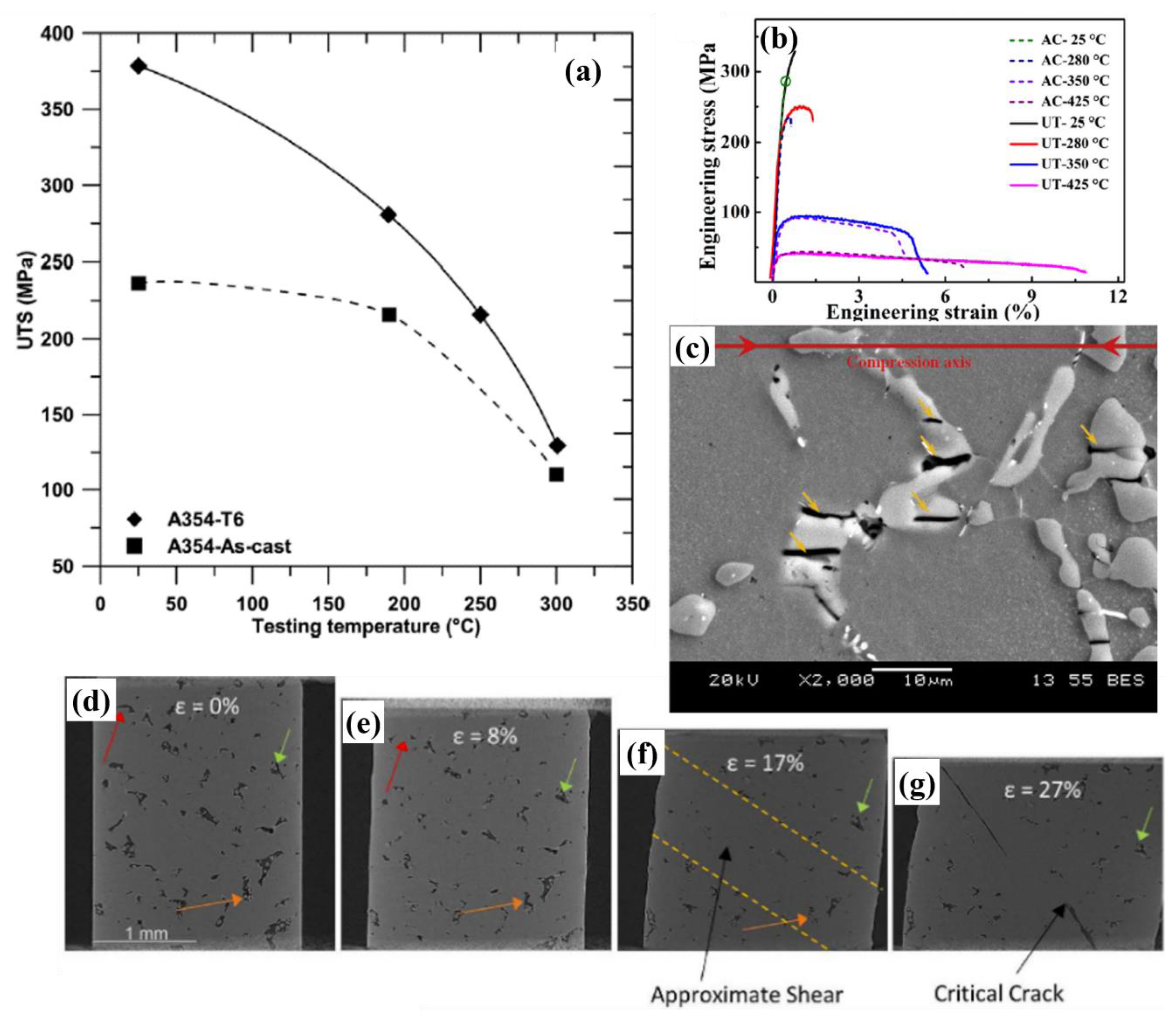
5.2.5. High Temperature Response

Al-Si alloys undergo significant softening when operated at higher temperatures. These alloys require a good static response under elevated temperatures to be applicable in the casting of engine blocks, cylinder heads, pistons, catalytic converters, and exhaust components. Sandoval [238] studied the changes in the UTS of A354 alloy under cast and T6 conditions as a function of temperature, which showed a significant reduction in UTS at higher temperatures due to the coarsening and/or dissolution of Cu- and Mg- rich particles (Figure 10a). Upon Ostwald ripening, these particles grew beyond a certain size, which reduces strengthening. Only in the presence of optimized Si particle size, precipitates (such as Mg2Si, Al2Cu), and dispersoids, can Ostwald ripening be slowed down and help the alloys retain their strength [239]. Figure 10b shows the high-temperature engineering stress–strain curves for Al-12%Si piston alloys after gravity casting (AC) and ultrasonic melt treatment (UT). The UTS in both groups showed a similar trend in terms of significant decrease upon testing beyond 350 °C, whereas elongation increased [173]. The UT alloy group showed comparatively better UTS and elongation than AC alloys, owing to the greater refinement of primary Si, intermetallic phases, and grains. Czerwinski [27] recently summarized various modifications made by the addition of transition metals (TM) and rare-earth (RE) elements, which help enhance the high-temperature stability of Al alloys. Zr has been considered the best TM to be added to Al-Si alloys, which improves high-temperature strength by the formation of binary trialuminides in the microstructure [239]. Mohamed et al. [240] considered Ni, along with Zr to A354 alloys, and observed that up to 0.4% addition showed optimal high-temperature strength. Colombo et al. [241] added ~0.3% Er to A356 alloys, which resulted in the optimal combination of thermally stable and coarsening-resistant Er-containing dispersoids in the microstructure. Additionally, several researchers have tried to add ceramic particles, such as graphite, ZnO, etc., to Al-Si alloys, which can help improve thermal properties [242].

5.2.6. Fracture Behavior

From the summary on the microstructures of Al-Si alloys (Section 4) and the related mechanical properties in this section until now, it is explicitly known that microstructural features control the failure and damage mechanisms of Al-Si alloys. Several studies have predicted, modeled, and calculated the crack nucleation regions under static uniaxial loading using experimental characterization techniques and atomistic or molecular dynamic simulations [243,244,245]. With adequate experimental evidence, failure under tensile or compressive loading involves particle cracking or debonding, microcrack formation, and growth. Shaha et al. [246] observed that during the tensile plastic deformation of an Al-Si alloy with Zr, V, and Ti, the eutectic Si particles and intermetallics cracked earlier than the matrix. The increased size of intermetallics or brittle phases also result in easier fracture due to the larger defect susceptibility and stress concentration [247]. The orientation of particles, with respect to the loading axis, also plays a major role in cracking behavior [248,249,250]. In an Al-Si-Zr-V-Ti alloy studied, the cracks developed in the intermetallics and eutectic Si particles, which were parallel to the compressive axis under hot compression loading at 200 °C (Figure 10c) [251]. Most of the tensile or compressive cracks in Al-Si alloys propagate through the interface of Al-Si particles, with subsequent debonding of Si from the Al matrix. Gall et al. [248] atomistically studied the mechanism of crack initiation at the interface of Al and Si phases, in general, for such binary alloys. The [100]Al || [100]Si incoherent interface between the Al matrix and Si has a rippled structure, with respect to a perfect interface. When there are no vacancies, dislocations, impurities, or other defects present, the interfacial fracture occurs at the location where the local displacement of atoms creates the rippled structure. This results in interfacial debonding before the bulk Al and Si failure ahead of the crack tip. As inherent material defects due to fabrication or heat treatment also play a major role in affecting the elongation and other static mechanical properties of an Al-Si alloy, Johnson et al. [131] studied the effect of pores in a L-PBF AlSi10Mg alloy under compression as shown in Figure 10d–g. The pores become heavily deformed as compressive loading progresses, leading to flattening and closing. This phenomenon is discerning for the pores inside the shear band (yellow dotted lines). The pores outside the shear band maintain their original shape until the sample fails.
Figure 10. (a) UTS values of A354 alloy in cast and T6 conditions as a function of testing temperature [238]. (b) Tensile stress–strain curves of an Al-Si piston alloy at different testing temperatures (AC: as-cast; and UT: ultrasonic melt treatment) [173]. (c) SEM image showing particle cracking of a modified Al-7%Si alloy after compression tests at a strain rate of 1 s−1 and 200 °C, where yellow arrows indicate the cracks in the Si particles [251]. (dg) Evolution of porosity and damage using X-ray computed tomography in an L-PBF Al-10%Si-Mg alloy under in situ compressive loading [131]. Reproduced with permission from Elsevier.
Metals 13 00609 g010

6. Fatigue Behavior of Al-Si Alloys

Understanding the static deformation behavior of Al-Si alloys is a topic that is well established in the research community. In order to make these alloys viable for the automotive and aerospace industries, extensive studies are needed to understand their fatigue or cyclic loading properties. Some fatigue-based studies for Al-Si alloys include A356 alloys, A357 alloys [252,253], and A319 alloys [72,254,255]. However, with technological advancements in manufacturing routes and in modifying microstructural features, as discussed in Section 3 and Section 4, there is an ever-growing need to study cyclic deformation mechanisms and understand the factors that control the fatigue failure of newly developed Al-Si alloys. Furthermore, a perceptible comparison between fatigue strength and durability between cast Al-Si alloys to recently developed AM Al-Si alloys is warranted.
Fatigue tests can be broadly classified into two important types, namely stress-controlled fatigue, also known as high-cycle fatigue (HCF), and strain-controlled fatigue, also known as low-cycle fatigue (LCF). Both types of fatigue tests are conducted with specimens following ASTM standards (ASTM E466 and ASTM E606, respectively). Figure 11a,b show the geometry and dimensions of typical fatigue test specimens used for HCF and LCF tests, respectively, which could be obtained either from casting or after extraction from final components (Figure 11c) [86,95,256,257]. Industrial-level tests include the staircase method (a type of load-controlled test) and fatigue durability testing of in-service components. Although there is no official standard on the total number of cycles that need to be achieved for successful test completion, researchers generally use a ‘life goal’ of 1 × 10⁷ cycles [258].
Intrinsic fatigue properties are generally determined for Al-Si alloys with standardized specimens. These properties are highly influenced by the metallurgical characteristics of the material, such as the composition, structure, grain size and fabrication method, specimen form, and heat-treatment conditions. Moreover, the size effect of the specimens, along with the testing method, the presence of mean stress, residual stresses, notches, microstructural heterogeneities, and the surface finish, significantly affect the fatigue durability of Al-Si alloys. Whether the alloy has been fabricated through casting or additive manufacturing route, there is a certain set of dimensional protocol that needs to be adhered to for the machining or polishing of the samples before fatigue testing. The specimens with varying surface roughness after casting or printing may not be appropriate to yield reliable fatigue results, thus further machining is needed. Common theories suggest that the presence of stress concentrators severely reduce the fatigue strength of materials, due to the stress redistribution caused by local yielding, which is not so strong in static uniaxial loading [258]. This article summarizes recent advances in the fatigue studies of Al-Si alloys in both HCF and LCF regimes.

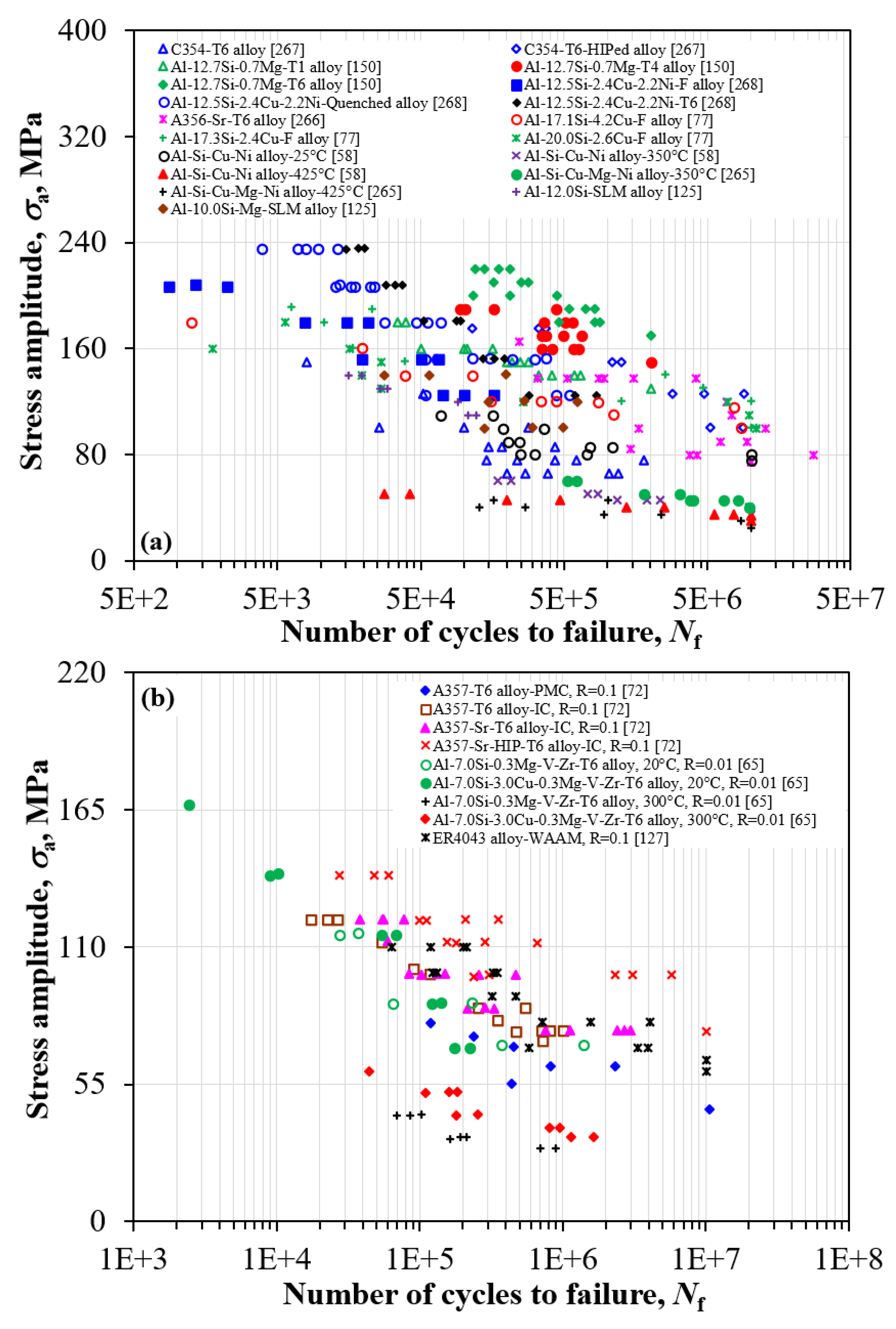
6.1. High-Cycle Fatigue

Earlier studies depicting HCF testing estimated the fatigue limit (or endurance limit) of common industrial Al-Si alloys, such as A356, A380, A319 alloys, etc. [72,252,253]. Recently there has been some modifications in fabrication and manufacturing technology, along with the development of advanced Al-Si alloys. Therefore, more HCF data have been presented in the literature. Table 5 summarizes the fatigue strength for some of these recently developed Al-Si alloys, along with their heat-treatment conditions, loading mode, stress ratio, test temperatures, and porosity levels, where available [58,65,72,80,257,259,260,261,262,263,264,265]. The fatigue testing conditions differ based on the application of a certain casting product, which determines the loading mode. Uniaxial (or pull–push) cyclic loading is the most common setup for standardized tests of fatigue properties using ASTM-based specimens (Figure 11a). Some applications, such as Al-Si piston alloys, demand the understanding of bending and rotational fatigue [259]. It is essential for the automotive and aerospace industries to understand the nature of fatigue behavior of different Al-Si alloys (such as hypoeutectic or hypereutectic alloys) with various chemical modifications fabricated through different casting routes.
The presence of Si in Al alloys exhibits a variety of shapes and structures in the primary α-Al phase, as described in Section 4.1. Fatigue life is heavily influenced by the presence of such heterogeneous microstructures in Al-Si alloys, along with modifications of particle shape, morphology, size, and distribution in the alloy. An Al-9%Si (A380) alloy [80] tested under uniaxial HCF loading showed improved fatigue strength in the T6 condition (260 MPa), compared with the as-cast (F, 205 MPa) or T4 (240 MPa) conditions. This study was also one of the first to report that the endurance limit of the as-cast and T4 alloys was higher than the 0.2% offset yield stress for the respective alloys, which is uncommon for metallic materials. For castings, the fatigue life at any given stress level is determined by the presence of the largest defect in the specimen. It is important to note that die-cast components have a smooth surface finish, in contrast to machined specimens, without a susceptibility for fatigue crack initiation from critical regions. Furthermore, the pressure die-cast components have finer microstructures, free from defects or pores at the “skin” or sub-surface layer (within ~400 μm), which exhibit higher fatigue resistance [80].
Figure 12 summarizes the cyclic stress amplitude vs. the number of cycles (S-N) curve data points collected from the open literature to compare the effects of casting processes, post-processing techniques, microstructural features, mean stress, and testing temperatures on the HCF behavior of Al-Si alloys [58,65,72,77,125,127,150,265,266,267,268]. HCF tests completed under fully reversed conditions (stress ratio, Rσ = −1) are shown in Figure 12a, whereas the tests with a certain level of mean stress (Rσ ≠ −1) are summarized in Figure 12b. The effect of alloying elements can be seen from the study by Wang et al. [77], where a hypereutectic Al-Si-Cu alloy with lower Si and Cu content displays a higher fatigue performance than others. It can be ascertained that the T6 heat treatment of Al-12%Si alloys containing Mg (Liu et al. [150]) and Cu (Rezanezhad et al. [268]) shows higher fatigue strength under HCF condition in comparison with the F, T1, T4, or quenched counterparts. Although no proper emphasis was given to the effect of the porosity fraction upon heat treatment in these studies, earlier studies depicted the increase in the porosity fraction in the Al-Si alloys due to solutionizing [81].
The majority of damage during fatigue loading of Al-Si alloys presented in the open literature is due to the presence of pores. These pores can be classified into two distinct types, namely internal and surface discontinuities. The internal pores have two sharp edges, whereas the surface pores have only one sharp edge. Surface pores are the most frequent locations for fatigue crack initiation in Al-Si cast alloys [77,269]. Casting defects with one sharp edge lead to excess localized stress concentration and are more detrimental to fatigue life [29,270]. When components with complex geometry or components containing multiple bolt holes are cast, the possibility of surface discontinuities remain high.
The presence of discontinuities is observed more in the case of sand cast alloys, whereas a reduced possibility of surface pores can be seen in HPDC and sand casting with a roll-forming setup [258]. In the case of specific castings, such as precision sand casting or semi-permanent-mold castings, it becomes difficult to cast in bolt holes. Furthermore, post-cast drilling and machining operations induce a higher chance of opening an internal discontinuity in the surface. Figure 13a gives a detailed schematic of the stress distribution around the internal and surface pores. The surface pores give a higher stress gradient from the surface to the center of the specimen, leading to non-uniform stress distribution and causing crack initiation [271]. Another example showing HCF crack initiation in Al-Si-Cu-T6 and A356-T6 alloys at room temperature (RT) is shown in Figure 13b,c, respectively, with the crack radiating away from the near-surface pores [266,270]. Although the presence of internal pores does not lead to instant fatigue crack nucleation, the increased area fraction of pores leads to a loss of static strength in the material, leading to lower fatigue strength. Some of the internal pores in an as-cast C354-T6 alloy can be seen in [267].
Another parameter affecting the fatigue behavior of cast alloys is the SDAS, which reflects the effect of cooling rate during solidification. Permanent-mold and sand casting have a higher cooling rate than investment casting, resulting in finer dendrites. This results in higher static and fatigue properties in the alloy fabricated through permanent mold and sand castings [72]. As fatigue properties are strongly ‘stress raiser’-dependent, rounded and finer phases improve the fatigue life of the material [272]. As seen from Section 4.3, several modifiers, such as Sr, result in more rounded and fibrous eutectic structures, leading to a significant increase in fatigue strength, even at the expense of increased porosity due to Sr addition [72]. Figure 12b shows the comparison of several S-N data under HCF loading for Al-Si alloys, with the application of a certain mean stress (Rσ ≠ −1). The fatigue life of A357 alloys under T6 conditions, fabricated with investment casting, (brown square) was obtained at a higher rate than that of the same alloy fabricated through permanent-mold casting (blue diamond), and this further improves upon Sr modification (magenta triangle) and HIP post-processing (red cross). This was possible due to a faster cooling rate achieved during IC, which refined the microstructure to an SDAS value of 47 μm [72]. Compared to other Al-Si alloys in Table 5, the IC A357 alloy after Sr addition and HIP shows improved fatigue properties than other gravity die and sand cast alloys tested at room temperature [58,260,261,264].
Thermal stability of the Al-Si alloys under fatigue loading needs to be addressed as the components being manufactured for automotive or aerospace applications do not always operate at RT. Figure 12a also compares the HCF behavior at RT and elevated temperatures of 350 °C and 425 °C for the Al-Si-Cu-Ni-Mg piston alloys [58,265]. The trend shows a decrease in fatigue performance upon increasing temperature. The effect of temperature on Al-Si-Cu alloys was also studied by Mori et al. [65] to understand the addition of transition metals such V and Zr at RT and 300 °C, where the HCF life at RT was longer than that at 300 °C. These studies show that the loss of static strength at elevated temperatures can cause a significant decrease in the fatigue strength of the materials [273]. At elevated temperatures, oxide films lead to crack initiation at the interior but are not the governing failure criterion. The surface pores are still the most preferential sites for major crack nucleation and final failure.
With emerging AM technology, certain grades of Al-Si alloy prototypes manufactured from SLM [125] and WAAM [127] have recently been studied for their HCF behavior. Al-12%Si and Al-10%Si-Mg alloys showed comparable fatigue behavior among themselves and are also in the range of other cast Al-12.5%Si [268] and Al-Si-Cu-Ni alloys [58] (Figure 12a). From Figure 12b, it is seen that WAAM Al-Si alloys (ER4043 alloy) [127] show enhanced fatigue life and are within the range of the A357-T6 cast alloys [72]. Although the fatigue life of AM components strongly depends on the surface roughness of the specimens, along with the Al-Si cellular microstructures, HCF cracks generally nucleate from either of these two regions [274].

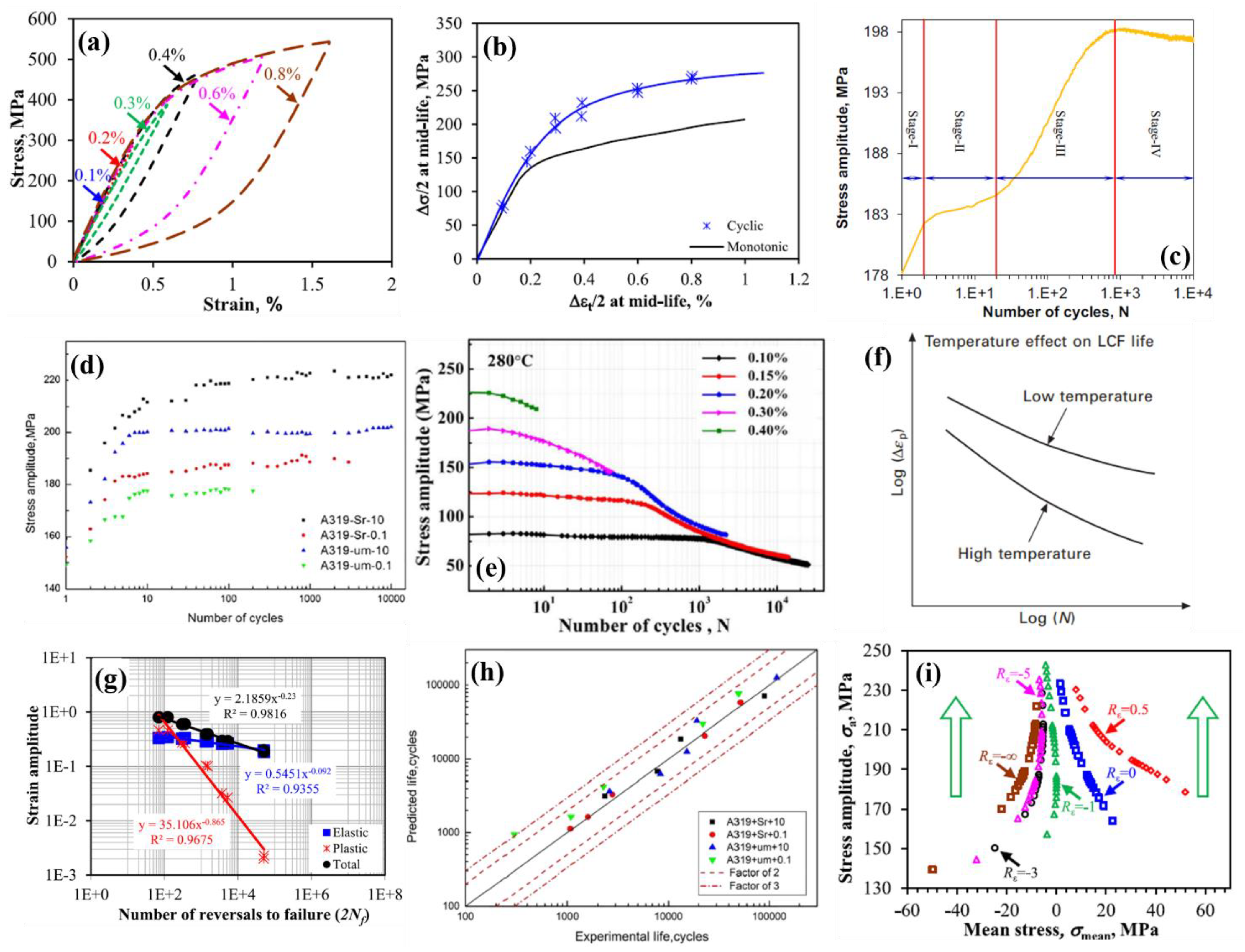
6.2. Low-Cycle Fatigue

Low-cycle fatigue is the most common evaluation method for the industrial qualification of alloys, especially in the automotive sector. LCF is often characterized by its high-stress amplitudes and low frequencies, which produce stresses spanning both elastic and plastic regimes. The presence of plastic strains in a material makes it highly susceptible to geometric discontinuities or stress risers, which lead to failure at a reduced number of cycles compared to HCF. Notable factors that affect the LCF behavior of a component or material are cooling holes, discontinued geometries such as notches, interior channels, material imperfections that originate during manufacturing or machining processes, and thermal gradients [275]. These tests are performed in a servomechanical or servo-hydraulic system with specially designed control parameters and test specimens (Figure 11b). The general method of presenting LCF data is to plot the total strain amplitude (Δεt/2) vs. the number of cycles to failure (Nf) in a double-log scale (known as the ε-N plot) (Figure 14) [61,62,64,86,87,95,148,149,230,276,277,278,279,280,281,282,283]. The alloys need to have a certain minimum amount of ductility to be tested under LCF to be able to withstand cyclic plastic strain during loading. Only high strength can reduce the component life under LCF [275].
Characterizing the LCF behavior can be conducted using several physical parameters, namely cyclic stress amplitude, plastic strain amplitude, hysteresis stress–strain loops, strain-energy density, etc. The Coffin–Manson relationship relating the plastic strain range to Nf is commonly used to describe the LCF regime. To facilitate the fatigue life estimation via the applied total strain amplitude (Δεt/2), Basquin’s equation and the Coffin–Manson relationship in relation to elastic strain amplitudes (Δεe/2) and plastic strain amplitude (Δεp/2), respectively, are combined into the total strain amplitude, which can be expressed as follows:
Δ ε t 2 = Δ ε e 2 + Δ ε p 2 = σ f 2 N f b E + ε f 2 N f c .
where E is Young’s modulus, Nf is the number of cycles to failure or fatigue life (2Nf is referred to as the number of reversals to failure), σf is the fatigue strength coefficient, b is the Basquin exponent (also known as the fatigue strength exponent), εf is the fatigue ductility coefficient, and c is the fatigue ductility exponent [86,148].
The importance of LCF comes into the picture when the presence of cyclic thermal stress of a higher amplitude arises, like that in diesel and turbine engines. A summary of LCF results for several cast Al-Si alloys is shown in Figure 14. The plot compares the fatigue life of Al-Si alloys cast though different routes, with different chemical compositions and varying heat-treatment procedures. If a specimen does not fail beyond 107 cycles at a given strain amplitude, the data points are depicted with arrows, meaning ‘run-out’. These curves follow a parabolic path where fatigue life decreases with increasing total strain amplitude. The LCF data from conventionally cast A319 and A356 alloys at varying tempers fabricated through different processes can be seen in Figure 14. The majority of studies have been reported in the T6 condition, which is the most common heat treatment for peak hardening. Ge et al. [61] showed the effect of Sr modifications on the eutectic structure and SDAS of A319-T6 alloys (Figure 14: red plus and blue cross), which reduced the mean free path for the dislocation slip and improved the fatigue life due to the higher energy required for nucleation and propagation of the crack. The effect of the cooling rate reported by Zhou et al. [62] also shows an improvement in fatigue life of the A319-T6 alloys solidified at a higher solidification cooling rate (HSCR, green plus) than that at a lower solidification cooling rate (LSCR, blue square). A356-T6 alloys studied by Emami et al. [276] showed the highest fatigue life at different strain amplitudes compared to other A356 alloys. A similar alloy was fabricated using the LPDC method into automotive wheels, and it was then sampled for LCF by Song et al. [95]. Although these alloys were from the same grades, the casting process controlled the advantages of one over another, resulting in a lower fatigue life in the latter.
Chen et al. [277] compared the elevated LCF (300 °C) properties of both A356-T7 and A319-T7 alloys, where the A356 alloy with finer and dense β-Mg2Si precipitates that promote cross-slip and homogeneous slip distribution, had a longer fatigue life than the A319 alloy with larger Al2Cu precipitates. Furthermore, the addition of Mo to the A356-T7 alloy led to a detrimental effect on the high-temperature LCF life [279]. The addition of alloying elements such as Ti, V, and Zr to Al-Si-Cu-Mg alloys was studied by Elhadari et al. [64] and Shaha et al. [280], where the addition of all three elements together helped to improve fatigue life more than only the addition of Ti. The TM elements led to the formation of trialuminide phases, which improve cyclic yield strength and result in a higher capacity of dislocation storage, thereby increasing fatigue life. Recent developments of similar Al-Si alloy variants with micro-additions of TMs like Ni, V, Sc, Zr, Ti, etc., have also led to the nucleation of compounds such as Al3Sc, Al3Zr, Al3V, and Al3(Zrx,V1−x), which act as strengthening phases due to their ordered L12 crystal structure [2,27].
Thermomechanical fatigue (TMF) studies under LCF loading a show reversed trend to the HCF tests. Some of the LCF life of Al-Si alloys loaded under TMF are also presented in Figure 14 [277,279,281,283]. An increase in temperature increases plastic deformation homogeneity and refinement of microstructures, which improve resistance to crack initiation, thereby increasing fatigue life. In simple terms, as the materials become more ductile, they have higher capacity to store more damage before failure, unlike in HCF where static strength controls the damage-bearing capacity [283]. Newly developed Al-Si alloys with low Fe content, fabricated using HPDC, were also studied for LCF behavior by Dash et al. [85,86,148,149]. The alloy was studied under as-cast, T4, and T7 conditions at RT and showed good fatigue resistance compared with other commercially used Al-Si alloys. Improved heterogenous microstructures without the presence of brittle Fe-bearing intermetallics resulted in better LCF properties in the alloy.

6.2.1. Assessment of Damage in LCF

When a component is subjected to a constant stress amplitude below the endurance limit, theoretically there should be no crack initiated in the material. However, repeated cycling in the elastic region could still accumulate a certain amount of damage. In LCF, as the strain crosses the plastic barrier at certain strain amplitudes, each cycle leads to an accumulation of damage in the material. The quantification of this damage has been studied through several physical parameters that can be controlled or derived from a fatigue test. Figure 15a shows the stress–strain hysteresis loops of the mid-life cycle for a newly developed Al-10%Si alloys at 0.6% total strain amplitude [86]. Aluminum alloys generally show symmetric hysteresis loops at different strain amplitudes, whereas some HCP alloys such as Mg have asymmetric loops due to the occurrence of twinning and detwinning during cyclic loading [284,285,286]. The loops, if translated to the origin as shown in Figure 15a, may show either Masing behavior or non-Masing behavior, depending on the overlap of the tensile arm. When the shifted curves almost coincide with each other, the material shows Masing behavior. Borrego et al. [287] studied the influence of dislocation–dislocation interactions on dislocation–precipitate interactions in the cyclic deformation of Al-Mg-Si alloys and observed that dislocation–precipitate interactions promote non-Masing behavior, while the mutual interactions between dislocations promote Masing-type behavior. Dash et al. [86] studied the LCF of Silafont®-36 alloys, which showed a slight overlap of the curves at different strain amplitudes, indicating the presence of near-Masing behavior in the cast alloy. The alloy under T4 and T7 heat-treatment conditions did not show any overlap, reflecting non-Masing behavior in the presence of solutionizing and aging precipitates [148,149]. A similar phenomenon was observed by Tenkamp et al. [288] in die cast, sand cast, and additive-manufactured Al-7%Si-Mg and Al-10%Si-Mg alloys.
The saturation of fatigue damage is considered at a certain value of cycles, generally at mid-life cycles (Nf/2). The mid-life stress amplitude, if plotted against the mid-life strain amplitude, generates the cyclic stress–strain curve (CSSC) as shown in Figure 15b. In comparison with the monotonic stress–strain curve, cyclic hardening or the softening or stabilization of the material could be identified. In the case of cyclic hardening, there is an increase in the stress amplitude or a decrease in the plastic strain amplitude as shown in Figure 15b–d. Cyclic softening is accompanied by a decrease in the stress amplitude or an increase in the plastic strain amplitude of the material, as shown in Figure 15e. Cyclic stabilization is the stage attained when there is no fluctuation in the stress or plastic strain amplitude with each cycle until failure. The onset of cyclic stabilization was reported in many previous studies on Al-Si alloys, such as precision sand cast A319-T6 alloys solidified at different cooling rates by Zhou et al. [62], gravity casting using sand mold for A319-T6 alloys by Le et al. [289], and cast A356-T5 and A356-ModT6 (SHT at 549 °C for 20 min, quenching to 21–27 °C and artificial aging at 182 °C for 8 h, all in the SiC sand fluidized bed) by Emami et al. [276]. The cyclic hardening in a cast Al-7%Si-T6 alloy documented by Shaha et al. [230] occurred in four stages as shown in Figure 15c. Stage I shows the start of stress hardening; stage II shows the constant stress amplitude period; stage III shows the second rapid hardening; and stage IV shows the second constant stress amplitude, leading to failure of the alloy. While most of the stages are clearly observable at lower total strain amplitudes for some materials, some stages disappear as the number of cycles reduces at higher strain amplitudes, with only stages II and III still discernible. Figure 15d from Ge et al. [61] shows all four stages with different intervals for different variants of A319-T6 alloys. Some of the Al-Si alloys that showed cyclic hardening are presented in [57,276,280,289]. Wang et al. [173] and others [283,290] showed that Al-Si alloys at elevated temperatures display cyclic softening phenomenon more clearly (Figure 15e). Azadi et al. [57] showed the transition between cyclic hardening and softening in Al-Si piston alloys when LCF-tested at RT and 200 °C. The LCF at elevated temperatures, especially for applications such as diesel engines, is usually caused by large thermal stresses at high component temperatures that are higher than the creep temperature. Fatigue life at elevated temperatures is significantly lower than that at lower temperatures as shown in Figure 15f [275]. Material ductility is affected by temperature and is a major factor in determining LCF life. Moreover, if the frequency of the loading cycle decreases, high-temperature LCF life will reduce because creep and oxidation play more prominent roles at lower cycle frequencies.

6.2.2. Existing Models to Predict Fatigue Life

Fatigue damage models for HCF and LCF have a long history, especially in uniaxial loading conditions [291]. Complex loading conditions such as non-proportional loading, torsional stress states, in-phase or out-of-phase multiaxial stress states, etc., have more practical applications in automotive, aerospace, and power-generation structural components [292]. Although the variable loading conditions and stress-based models are outside the scope of this article, advancements in fatigue damage models based on uniaxial LCF loading have been briefed in this section for some Al-Si alloys.
LCF models are established from the basic strain-life parameters in Equation (2), which can be presented as a double-log plot with the mid-life total strain amplitude as the summation of the mid-life elastic and plastic strain amplitudes, as shown in Figure 15g. The cyclic strain-hardening exponent (n′) and cyclic strength coefficient (K′) can be evaluated via the following relationship [165,230,293]:
Δ σ 2 = K Δ ε p 2 n ,
where Δσ is the mid-life stress range and Δεp is the corresponding mid-life plastic strain range. The LCF parameters obtained from Equation (2) from various LCF tests at RT or elevated temperatures for Al-Si alloys are summarized in Table 6 [61,62,64,86,95,148,230,276,277,278,279,280,281,283,289,294]. From several strain-based models, one of the promising models in the case of biaxial low-cycle fatigue was proposed by Brown and Miller [295], which represents a modified version of Equation (2). The model parameters included maximum shear strain range (Δγmax) and normal strain range (Δεn) on the plane experiencing maximum shear as follows:
Δ γ max 2 + S Δ ε n = A σ f 2 σ n , mean E 2 N f b + B ε f 2 N f c ,
where σn,mean is the mean normal stress; and S, A, and B are material constants. Several modifications were further proposed to Equation (4) by Wang and Brown [296] by adding the strain-path effect.
Furthermore, the Smith, Watson, and Topper (SWT) model [297] included normal strain range and maximum normal stress (σn,max) on the critical plane of normal stress to reflect the effect of mean stress as follows:
σ n , max Δ ε 1 2 = σ f 2   E 2 N f 2 b + σ f ε f 2 N f b + c ,
where Δε1 is the principal strain range. These models were used to predict the multiaxial stress-based fatigue life, but they could also be used for uniaxial fatigue, which also has a shear component and/or mean stress.
Nevertheless, these models are limited to applied shear and normal stress and strains on the material, without considering the accumulation of damage during LCF loading that eventually leads to fatigue failure. A cumulative damage model for predicting fatigue life in HCF tests was first introduced by Palmgren and Miner [298,299], which was also known as the linear damage-accumulation rule (LDR), as follows:
D = i = 1 k n i N i = 1 ,
where D is the total fatigue damage, n represents the number of cycles of operation at a given stress level, N represents the fatigue life at the same stress level, and “i” represents each cycle. According to the LDR, when the summation of damage in each cycle reaches 1, the material fails. However, there were some shortcomings of the LDR rule, including the following: (i) no information about the energy absorbed per cycle; (ii) no directionality/sequential behavior of the damage; and (iii) no inherent material behavior. Several models further modified the Palmgren–Miner rule, such as the two-stage linear damage theory, double linear damage theory, damage curve approach, etc., which have been summarized in [298].
LCF tests have macroscopic strain as a dominant factor, which cannot be accurately represented by Equation (6). Fatigue damage models in the case of LCF capture the general essence of key parameters, such as the mean stress, stress amplitude, and plastic strain amplitude obtained from each stress–strain cycle. Several researchers [298,300] presented a unified model to study the fatigue damage in both HCF and LCF regimes. The total strain energy per cycle (ΔWt) can be calculated as the sum of the elastic (ΔWe) and plastic (ΔWp) strain energies as follows:
Δ W t = Δ W e + Δ W p .
The plastic portion of strain causes damage, and the elastic portion is responsible for opening the fatigue crack [301]. Many improvements have been made on this idea, with one special model by Zhu et al. [300], who developed a new energy-based fatigue-life-prediction model for turbine disk alloys, where they combined Equations (6) and (7) with Morrow’s equation for cyclic plastic strain energy and Masing’s hypothesis. The model states that strain energy density (namely the area under the stress–strain hysteresis loop) at mid-life (Wm) absorbed during a cycle can be expressed as:
W m = 4 · 1 n 1 + n · K · Δ ε p 2 1 + n ,
by using all the variables from Equations (2) and (3). Furthermore, based on the accumulation of damage at each cycle and different temperatures, the fatigue life can be predicted by the following:
F · W m · σ m a x 1 + n 1 m ( 1 + n ) N f = 1 ,
where F and m are material constants and σmax is the maximum/peak stress. Recent research on some A356-T6 and A357-T6 alloys [302], Al-12%Si-Cu-Ni-Mg alloys [294], Al-Si piston alloys [173,303,304] at elevated temperatures used Equation (9) to predict the LCF fatigue life. The LCF life of a newly developed HPDC Silafont®-36 alloy at RT was predicted via further modification of Equation (8), using another material constant known as the intrinsic fatigue toughness [86,148]. Tenkamp et al. [66] used the SWT damage parameter (PSWT) to relate the microstructure to the LCF and HCF regimes for cast Al-7%Si-0.3%Mg-T6 alloys and plotted the results in a P-N diagram. Ge et al. [61] used a model which related the microstructural features, such as SDAS and Si particle size of A319 alloys, to the fatigue parameters presented in Equation (2). The predicted fatigue life at different strain amplitudes is plotted against the experimental values in Figure 15h, under four different conditions with Sr modifications and two different cooling rates. Good agreement between the prediction and experiment is observed.

6.3. Effect of Mean Stress

Both stress-life (stress-controlled) and strain-life (strain-controlled) fatigue tests can be performed in scenarios in the presence or absence of mean stress. Fully reversed cyclic loading ensures the minimal effect of mean stress (either Rσ = −1 or Rε = −1) on the materials during cyclic loading. The early work by Gerber follows:
σ a σ a r + σ m σ u 2 = 1 ,
while Goodman proposed:
σ a σ a r + σ m σ u = 1 ,
where σa, σar, σm, and σu are the stress amplitude, stress amplitude for fully reversed loading, mean stress, and UTS, respectively [305]. These earlier mean stress correction models have undergone further modifications for both stress-life and strain-life curves by several researchers, such as Koh and Stephens, Morrow, Bridgman, Smith–Watson–Topper (SWT), Walker, Dowling, Ince, and others [306,307,308,309,310]. The models proposed by Morrow, SWT, and Walker show reasonably accurate predictions for most metals, although the Morrow model often gives grossly non-conservative life estimates for Al alloys [311].
During cyclic loading when the minimum and maximum strain amplitudes are not equal, a mean strain is added to the cycling. This does not lead to equal tensile and compressive stresses being applied on the specimen, which results in mean stress. The presence of tensile mean stress reduces fatigue strength, whereas the compressive mean stress has a minor effect on fatigue strength. When Al-Si alloys are used in structural applications that contain notches, corners, or joints, the fatigue strength of the component goes down further in the presence of mean stress. The tensile mean stress also affects significantly fatigue life by reducing the beneficial role of surface compressive residual stresses [306]. Several studies have shown that positive/tensile mean stresses are detrimental to fatigue life, whereas the negative/compressive mean stresses tend to be favorable [85,300,309,312,313]. As the number of cycles progresses during strain-controlled fatigue tests, the means stress values start to decrease and attain stability. This phenomenon is called mean stress relaxation (MSR). The tendency of the material to resist plastic deformation highly determines the ability of MSR to reach 0. Some materials fail before reaching a state of 0 mean stress. A few studies have analyzed this effect of mean stress under HCF or LCF loading conditions for Al-Si alloys and other Al alloys [313,314]. Some LCF studies in relation to the effect of mean stress are discussed here. Koh et al. [278] studied a permanent-mold cast Al-10%Si-T4 alloy with and without reinforcements under LCF at Rε = −1 and 0.5. The study predicted fatigue life considering the mean stress effect in terms of an energy parameter. However, it showed minimum influence of the presence of mean stress on fatigue life of the unreinforced Al-Si alloy. A recent study by Dash et al. [85] showed the behavior of an HPDC Al-10%Si alloy under mean strain conditions leading to MSR under LCF at various strain ratios, ranging from Rε = −∞ to 0.5 at a constant total strain amplitude, as shown in Figure 15i. According to Branco et al. [314], an equation to express the normalized mean stress was established as a function of the logarithm of N (the number of cycles) as follows:
σ mean σ mean , i = A 1 + A 2 log N + A 3   log N 2                 R ε = 0   and   0.5 ,
where A1, A2, and A3 are fitting coefficients, which are in turn related to the strain ratio and strain amplitude. The change in the normalized mean stress with N had a convex nature for Rε = 0 and 0.5, but a concave nature for Rε = −3, −5, and −∞, and was not plausible in Equation (12). Dash et al. [85] thus proposed the following new power-law-based equation:
σ mean σ mean , i = B   log N α                             R ε = 3 , 5 ,   and   ,
where the concave nature of mean stress relaxation for strain ratios below −1 is described. In Equation (13), B and α are fitting coefficients. Fan et al. [315] studied the microstructural effect, along with a change in strain ratios (Rε = −∞ to 0.1), pertaining to different mean stress conditions for a gravity cast Al-9%Si-3%Cu alloy, and observed the presence of a number of parallel slip bands in the Al matrix at Rε = −∞ and numerous cross-slip bands at Rε = 0 that led to cyclic stabilization. Further LCF studies on the effect of strain ratio for Al-Si alloys at different total strain amplitudes and at elevated temperatures are needed to understand the in-depth cyclic deformation mechanisms.

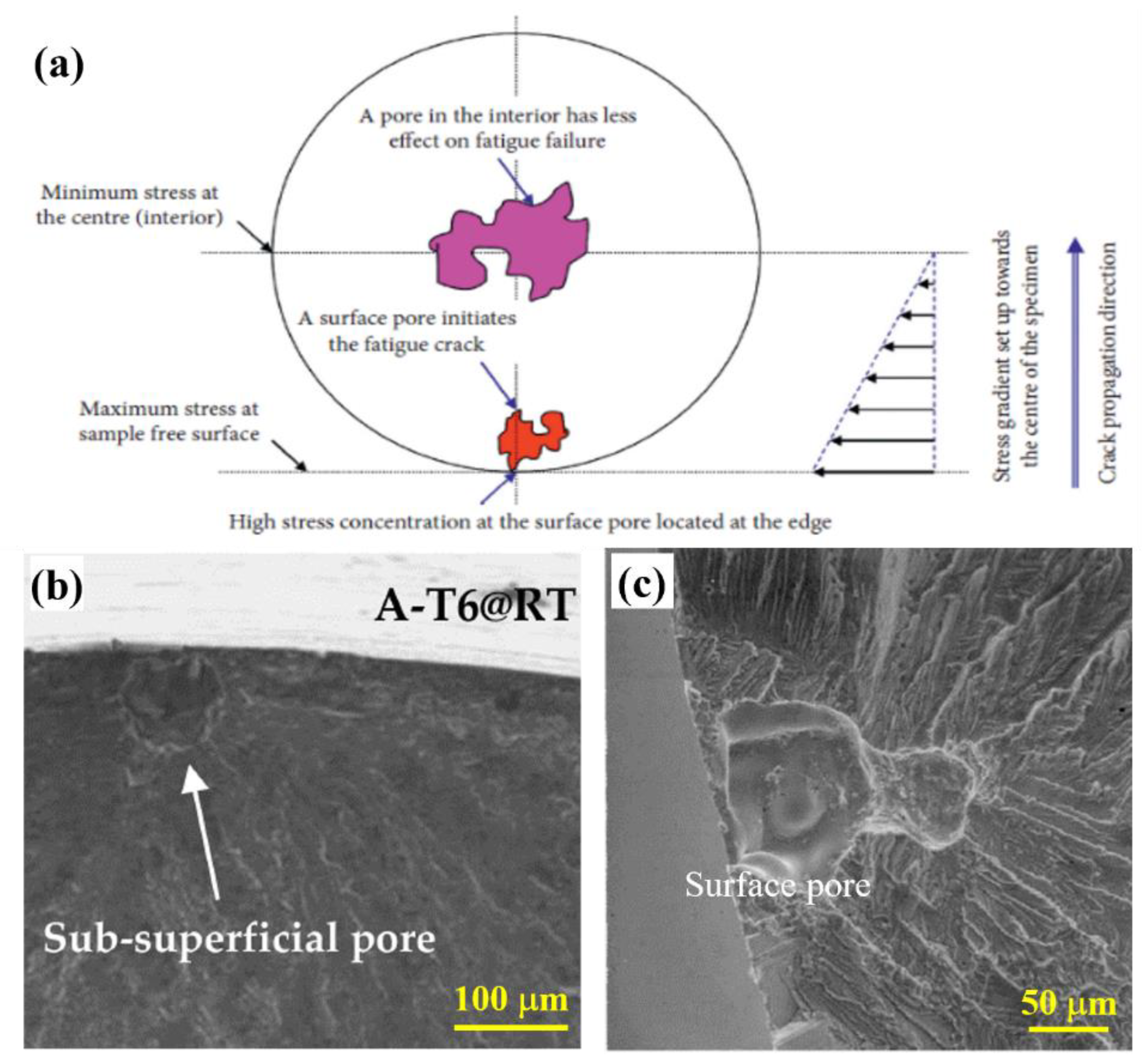
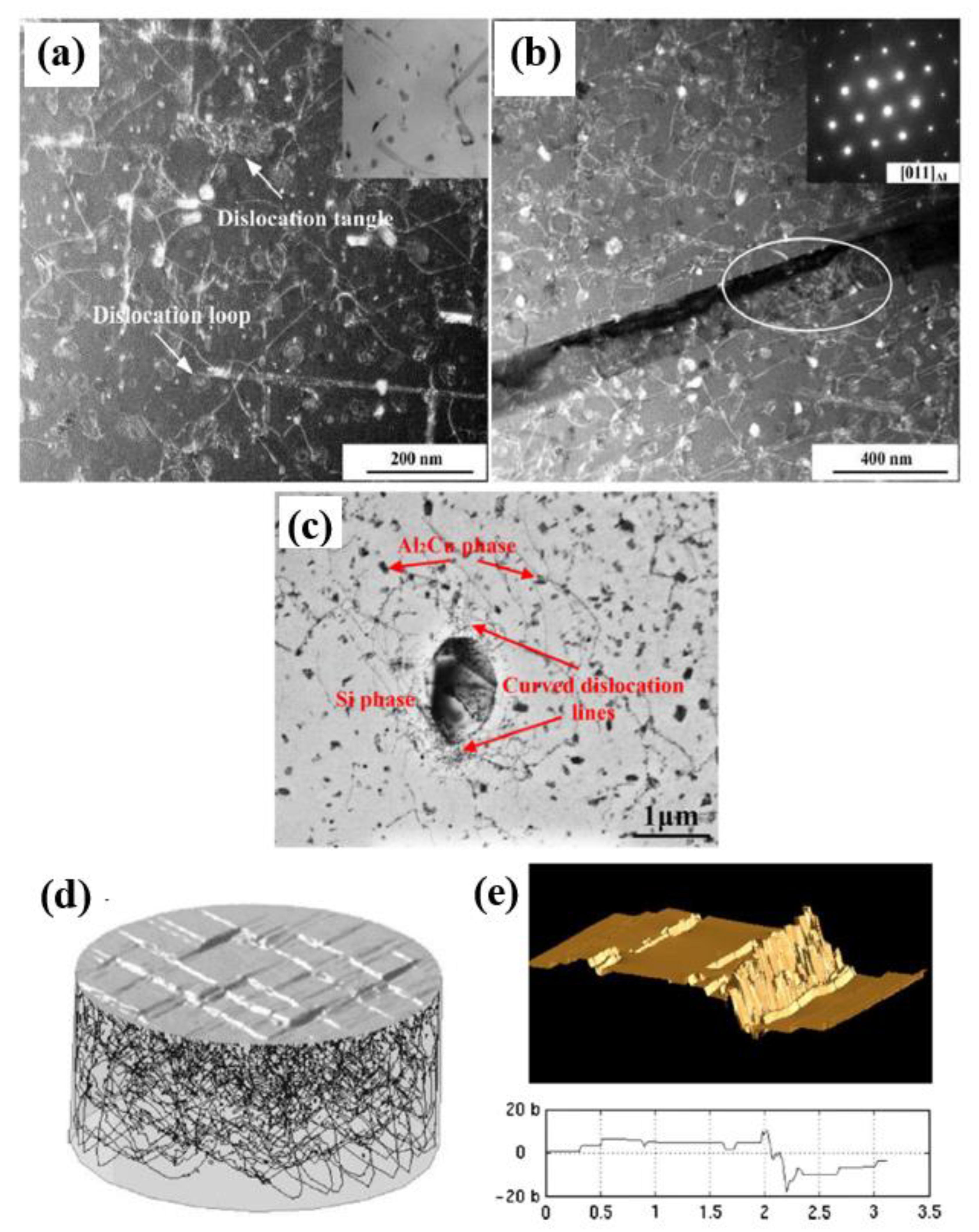
6.4. Fatigue Crack Initiation and Growth Mechanisms

Many studies on the deformation mechanisms during cyclic loading have demonstrated the role of microstructures in controlling fatigue crack initiation and propagation in a material. This article briefly summarizes fatigue crack initiation and growth mechanisms of Al-Si alloys in both HCF and LCF conditions. Any damage mechanism involves generation and motion of dislocations. How the generated dislocations react with the microstructure and nucleate a crack during stress- or strain-based cyclic loading for Al-Si alloys is a question that needs to be answered. The main reason for initiating a crack in fatigue loading is strain localization through a dislocation slip within the grains of a polycrystalline structure [316,317]. In ductile FCC metals, persistent slip bands (PSBs) are the ones causing crack initiation. During LCF, more dislocations are generated, e.g., via the Frank–Read dislocation multiplication mechanism. While some dislocations are annihilated in the reversed loading phase, further accumulation of residual dislocations/defects within the material continue as cyclic deformation proceeds. The PSBs increase with more accumulation and the existing bands widen, leading to the nucleation of small cracks in the material [317]. Several earlier studies have analyzed flow stress via underpinning dislocation mechanics, which form the basis of slip band formation [318]. Sangid [316] summarized the steps for the formation of ladder-like PSBs in a material, where the dislocation pattern creates varying hard and soft regions.
Figure 16a,b show the presence of highly dispersed dislocation loops and tangles in a cast Al-Si-Mg alloy with Zr and Hf after failure under high-temperature LCF at a strain amplitude of 0.3% [290]. Cycling at a temperature of 300 °C promotes rounded Si particles, overgrown precipitates, and dislocation climb, along with vacancies. The accumulation of dislocations at the interface of coarse Si particles and precipitates causes further strain fields that can act as crack initiation sites for LCF. Similar curved dislocations around coarse and rounded Si particles in an A319-T6 alloy under non-proportional LCF tests at an equivalent strain of 0.2% were also observed by Zhou et al. [62] (Figure 16c). The same group also performed another study on the effect of heat treatment on A319 alloys under non-proportional LCF, where dislocations were observed to be oriented in a cell structure near the fatigue crack [152]. In general, the network of dislocations arranged into slip bands was simulated by Déprés et al. [319] as a 3D dislocation dynamics image as shown in Figure 16d. Point defects are produced due to dynamic equilibrium between dislocation generation and annihilation. The flux of vacancies within the material produces intrusions and extrusions at the free surface or grain boundaries, as shown in Figure 16e [316]. Cross-slip is the main cause of dislocation dipole formation and is the origin of the irreversibility of the plastic strain. In polycrystals, the interface between grain boundaries and PSBs becomes a region of higher stress concentration, leading to crack nucleation [320,321]. Bogdanoff et al. [151] studied a permanent-mold cast Al-7%Si alloy with different Cu contents under cyclic loading, where in the alloy containing a lower Cu content, the slip bands were responsible for crack initiation. With increasing Cu content and the inherent strengthening of the α-Al matrix, the initiation locations shifted towards the interface of brittle Si particles and intermetallics within the α-Al matrix.
Although the nucleation of fatigue cracks occurs with the interplay of dislocations at heterogenous locations in the microstructure of Al-Si alloys, the presence of large-scale defects at the surface or sub-surface can accelerate the crack initiation process. It is evident from the history of cast Al alloys that the presence of Fe-based intermetallics, oxide particles, scales, gas, and shrinkage pores lead to regions of higher stress concentration and thus becomes the location of fatigue damage [151]. Huter et al. [262] further studied a range of cast Al-8%Si-Cu cylinder-head alloys under rotating–bending HCF and LCF with fully reversed cycling. The results showed the presence of a large number of microstructurally small cracks (MSCs) initiated within the network of brittle particles and micro-pores. The fraction of pores increased with the HT processes involving the solutionizing stage [81]. The lower fatigue life observed at different strain amplitudes can hence be related to the inherent loss in ductility due to excess porosity in the alloy.
The effect of crack length initiated from a defect that can cause fatigue failure is better evaluated by the Kitagawa–Takahashi threshold diagram [322]. As seen from Figure 13b,c, the adverse effect of surface and sub-surface pores is severe on HCF crack initiation and propagation, but the studies on LCF cracks have not shown a similar severity in Al-Si alloys. A study by Stolarz et al. [323] gave a concrete definition of how LCF crack initiation mostly occurs at the eutectic Al/Si interface, and fine porosity in the specimens do not significantly impact nucleation or growth mechanisms. Single and multiple cracking models created by the study showed that fatigue failure resistance increases if multiple microstructurally small cracks (MSCs) are present in the material. Lee et al. [250] developed several models for understanding the effect of MSCs on Si particles based on their shape and morphology in the eutectic structure. As fabrication process and HT affect the Si shape, it is important to characterize fatigue crack nucleation based on the appropriate Si particle type. Based on the morphology of Si particles in the Al-Si eutectic structure, either cracking or debonding would occur, as seen in [152]. Wang et al. [283] showed that high-temperature LCF cracks nucleated at broken eutectic Si or flaky intermetallic particle interfaces in a hypereutectic Al-Si piston alloy. Fan et al. [281] studied the high-temperature LCF features of an Al-Si-Cu alloy, where cyclic softening of the material occurred due to the dislocation climb through Al2Cu precipitates, and the coarse precipitates at the grain boundaries led to crack initiation.
Once fatigue crack is initiated, the next step of fatigue damage is crack propagation. The open literature contains in-depth research on the path the fatigue crack follows after its nucleation in Al-Si alloys. Here, some of these studies that can lead to a better understanding of alloy design to resist fatigue failure are summarized briefly. Figure 17a shows the nucleation of a microcrack within the eutectic structure, which then starts to propagate perpendicular to the loading direction as the number of cycles increase, as shown in Figure 17b. The crack leads to debonding or fracturing of Si particles along the path and also crosses the matrix at some preferred orientation [262]. Liu et al. [58] examined the secondary crack propagation in an Al-10%Si-T6 piston alloys under HCF, where the crack does not have a preferential path of propagation (Figure 17c,d). The crack can be seen to debond the intermetallics, Si particles in the eutectic, and Al grain boundaries. This study also shows that the grain boundaries are not involved in the initiation of fatigue crack due to the presence of the second phases. Another study by the same group [265] showed the presence of grain boundary cracking during HCF at 425 °C using EBSD, where the misorientation among the neighboring grains was even below 5° (Figure 17e,f). These studies were able to build a mechanism for HCF crack propagation at different temperatures (RT, 350 °C, and 425 °C), as shown in Figure 17g–i, respectively. At RT, all the constituents, Al matrix, Si particles, and intermetallics provide the propagation path (Figure 17g). With increasing temperature, as the grain boundary strength starts to weaken, the grain boundary and phase/matrix cracking mechanisms become more prominent (Figure 17h,i) [58]. Similar results were also reported by Joyce et al. [324] in near-eutectic Al-Si alloys.
Crack driving force plays an important role in determining the path of fatigue crack. Gall et al. [172] showed that when cracks are short with a lower driving force, they follow the stage I crack growth regime of the log(da/dN) vs. log(ΔK) curve. In this stage, the fatigue cracks propagate primarily along the interface between Si particles and the α-Al matrix, with some Si particles aligned perpendicular to the crack growth direction being fractured, while others are debonded. Once the crack driving force increases, cracks are characterized to be in stage II or the Paris law regime, and the brittle Si particles fracture ahead of the crack tip, along with some small particles that are debonded. Although these studies were carried out in the HCF regime, McDowell et al. [325] and Xue et al. [326,327] studied the similar behavior of fatigue crack growth in A356-T6 and A380-F Al-Si cast alloys in both LCF and HCF regimes. Another study by Huter et al. [262] summarized the crack growth mechanisms in Al-Si-Cu and Al-Si-Mg cast alloys in the schematic shown in Figure 17j, with significant events (SEs) that mostly influence the fatigue lifetime, such as the incubation of cracks in a low-plasticity fatigue case. In the high-plasticity case, the influence of eutectic particles is not strong, whereas the strength of the matrix plays a significant role in crack propagation. In the HCF regime beyond 106 cycles, a few cracks nucleate, making it a significant event. With the fatigue propagation rate being reduced by eutectic particles, the HCF regime would define all the propagation events as significant events which control the fatigue life.

7. Concluding Remarks and Future Outlook

7.1. Summary

Al-Si alloys are mainstream lightweight alloys used in the past, present, and future of the light metal automotive industry. This review article is an amalgamation of processing–structure–property studies, specifically on structural Al-Si alloys, including data mainly from recent developments within the last two decades or so. The following concluding remarks on Al-Si alloys from this review can be made:
  • Al-Si alloys with other alloying elements, such as Cu, Mg, Mn, Ni, etc., show excellent castability and heat treatability. Impurities such as Fe in these alloys have a significant impact on ductility and fatigue properties, for which they should be minimized. With increasing demand for hybrid and EVs, newer Al-Si alloys with the addition of transition metals, rare-earth elements, Ag, Sn, Cu, etc., have been developed to improve the thermal stability and electrical conductivity, along with strength and elongation.
  • The manufacturing practices of Al-Si alloys range considerably from casting to 3D printing (additively manufactured) alloys. Obtaining near-net-shaped products can be seen as a major objective for automotive and aerospace castings. Pressure die-casting techniques such as HPDC and LPDC, along with semi-solid metal processes, produce a variety of alloys with different microstructural features, depending upon mold parameters, cooling rate, vibration dynamics, etc., which control alloy performance.
  • Emerging techniques of additive manufacturing, such as WAAM, L-PBF, and others have also led to cellular microstructures that behave differently than cast alloys under mechanical loading. However, porosity issues in these alloys currently limit their applicability at an industrial scale.
  • The mechanical properties of these alloys under static and cyclic loading are closely related to their microstructures, intermetallics, porosities, surface features, and casting defects, etc. The presence of an Al-Si eutectic structure (modified or unmodified) imitates the behavior of particulate-reinforced composites, where the morphology of Si particles controls the failure mechanisms of the alloy. Like composite materials, the enhancement of Young’s modulus is a feature of Al-Si alloys with a Si content of >5%, which is controlled by the volume fraction of eutectic Si particles.
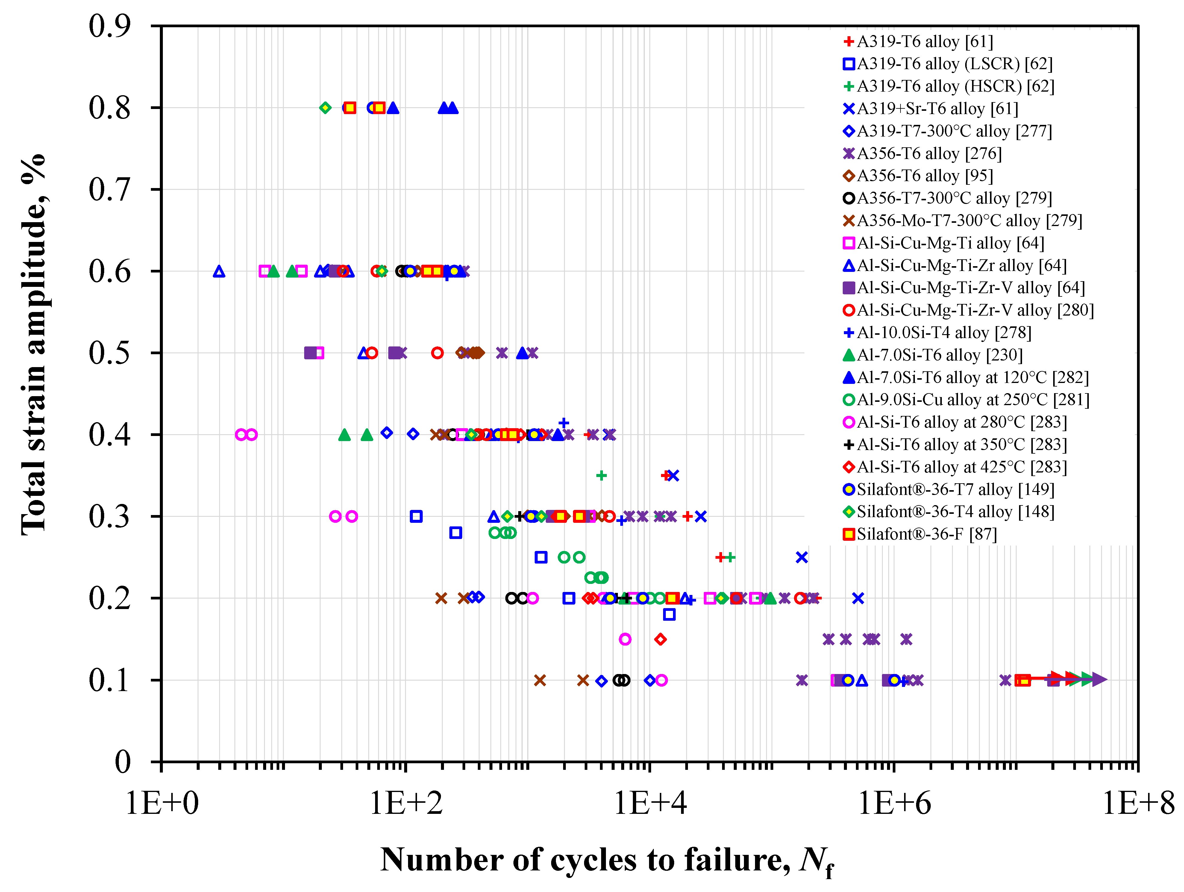
  • High-cycle and low-cycle fatigue mechanisms of alloys vary based on alloy composition, production route, sample size, heat-treatment conditions, and microstructures. It has been observed in many studies that alloys with higher static ductility perform better under strain-controlled LCF, while stress-controlled HCF strength is mainly associated with its static strength.
  • Damage mechanisms under fatigue were assessed based on the strain-energy density stored in the material during cyclic loading. Initiation of fatigue cracks occurred from multiple slip band intrusions and extrusions formed on the surface of the alloys due to the higher stress concentration. Failure also heavily depends upon the amount of surface or near-surface defects in the fabricated alloys. Methods to minimize the presence of defects in fabricated Al-Si alloys include controlling the solidification rate, alloy composition, surface treatment, eutectic morphology, intermetallics, and avoiding unwanted pores.

7.2. Future Outlook

Extraction and processing of primary Al alloys account for a high amount of carbon footprint, energy consumption, and GHG emissions. With the advent of extracting Al alloys using secondary/recycling routes, there has been significant reduction in carbon footprint and GHG emissions. Life-cycle assessment (LCA) models have focused on practices such as the midpoint and endpoint indicators, which have high potential for reducing the environmental burden. Carbon capture technology and optimization of the energy structure away from natural gas during alloy remelting, purifying, Si metal production, thermal power sources, etc., can reduce GHG emissions. It is thus important for researchers working on these alloys to continue to improve the fabrication processes based on these standards of carbon and energy utilization so as to avoid deleterious impacts to the environment.
There have been several innovations in the aspect of material characterization, which has helped improve the microstructure-related performance of Al-Si alloys. With improvements in the material characterization techniques, e.g., using EBSD and high-resolution TEM (HRTEM), researchers are able to monitor crystal orientation, grain size, precipitation kinetics, etc., which play an important role in controlling static and cyclic deformation behavior. Integration of computational and numerical-based simulation models (integrated computational materials engineering, ICME) and artificial intelligence (AI) technology are driving the forefront of current research on light metals. An extensive database from numerous experimental studies on Al-Si alloys has yielded the development of models to predict the mechanical properties based on the chemical composition and fabrication route of the alloys. Not only are these cost saving, but these models can also result in improved analyses of process and control parameters which lead to defect-free alloys with no or little porosity and hydrogen entrapment in Al-Si alloys. The solutionizing step during heat treatment of Al-Si alloys could lead to distortion of some as-cast components used in battery frames in EVs, which should be tackled by designing castable alloys either without the requirement of solutionizing step or improved performance in T5 condition.
Thermodynamics and phase field modeling impart more knowledge on precipitation kinetics and dispersion hardening of Al-Si alloys. Such models can be used to understand the role of minor alloying elements in recycled or secondary Al-Si alloys (also known as green alloys) and process them in a certain way to extract the best possible strengthening or crack bridging mechanisms that lead to a longer life of components. There has also been a growing interest in the area of Al-Si-based metal matrix composites by the addition of graphene, carbon nanotubes, etc., via casting or 3D-printing, which can improve electrical conductivity and grain refinement, leading to increased usage in EVs. As the current processes to do so are quite expensive, newer and more cost-effective methods needs to be found.
As fatigue is the one of the most common failure modes in Al-Si alloys used in automotive and aerospace components, crack initiation and propagation in relation to microstructural or surface characteristics have to be studied extensively. The physics behind fatigue damage under high- and low-cycle fatigue, whether uniaxial, multiaxial, or rotating–bending, needs to be understood. Non-destructive testing techniques such as far- and near-field high-energy XRD, and X-ray computed tomography are some of the advanced characterization tools used to detect defects and particle morphology and identify failure initiation locations in cast or 3D-printed Al-Si alloy components. Other material characterization techniques, such as 3D and 4D reconstruction of microstructures using in situ EBSD, are also helpful to identifying microstructural changes during cyclic loading, including grain size, shape, orientation, and topology, etc. Furthermore, integrating these experimental data with ICME and AI models to predict fatigue life more accurately can prevent catastrophic failure. Researchers and scientists still need to understand the physics-based connection of crack initiation by building the relationships between the complex microstructure, processing, mechanical property, and performance of Al-Si alloys for the safe structural applications in the automotive industry.

Author Contributions

Conceptualization, S.S.D. and D.C.; methodology, S.S.D.; validation, S.S.D. and D.C.; investigation, S.S.D. and D.C.; resources, D.C.; data curation, S.S.D.; writing—original draft preparation, S.S.D.; writing—review and editing, S.S.D. and D.C.; supervision, D.C.; project administration, D.C.; funding acquisition, D.C. All authors have read and agreed to the published version of the manuscript.

Funding

The authors would like to thank the Natural Sciences and Engineering Research Council of Canada (NSERC) for providing financial support.

Data Availability Statement

Not applicable.

Acknowledgments

This investigation involves part of research collaborations with D.J. Li and X.Q. Zeng of Shanghai Jiao Tong University, Shanghai, China; D.Y. Li of the University of Alberta, Edmonton, Canada; Y. Zou of the University of Toronto, Toronto, Canada; F. Czerwinski and W. Kasprzak of CanmetMATERIALS, Natural Resources Canada, Hamilton, Canada; and A. Luo of Ohio State University, Columbus, OH, USA. The authors would like to thank Messrs. Q. Li, A. Machin and J. Schwartz of Toronto Metropolitan University and S.M.A.K. Mohammed of Florida International University (Miami, FL, USA) for their assistance during the study.

Conflicts of Interest

The authors declare no conflict of interest.

References

  1. Net Zero by 2050. Available online: https://www.iea.org/reports/net-zero-by-2050 (accessed on 20 January 2023).
  2. Luo, A.A.; Sachdev, A.K.; Apelian, D. Alloy Development and Process Innovations for Light Metals Casting. J. Mater. Process. Technol. 2022, 306, 117606. [Google Scholar] [CrossRef]
  3. Net-Zero Emissions by 2050. Available online: https://www.canada.ca/en/services/environment/weather/climatechange/climate-plan/net-zero-emissions-2050.html (accessed on 20 January 2023).
  4. For a Livable Climate: Net-Zero Commitments Must Be Backed by Credible Action. Available online: https://www.un.org/en/climatechange/net-zero-coalition (accessed on 20 January 2023).
  5. Tran, M.-K.; Bhatti, A.; Vrolyk, R.; Wong, D.; Panchal, S.; Fowler, M.; Fraser, R. A Review of Range Extenders in Battery Electric Vehicles: Current Progress and Future Perspectives. World Electr. Veh. J. 2021, 12, 54. [Google Scholar] [CrossRef]
  6. Riley, C. The Great Electric Car Race Is Just Beginning. Available online: https://www.cnn.com/interactive/2019/08/business/electric-cars-audi-volkswagen-tesla/ (accessed on 20 January 2023).
  7. DuckerFrontier. 2020 North America Light Vehicle Aluminum Content and Outlook; DuckerFrontier: Washington, DC, USA, 2020. [Google Scholar]
  8. Aluminum Market Size And Forecast. Available online: https://www.verifiedmarketresearch.com/product/aluminum-market/ (accessed on 20 January 2023).
  9. Automotive Aluminum Market Size, Share & Trends Analysis Report by End Use (Passenger Cars, Light Commercial Vehicles, Heavy Commercial Vehicles), by Application, and Segment Forecasts, 2019–2025. Available online: https://www.grandviewresearch.com/industry-analysis/automotive-aluminum-market (accessed on 20 January 2023).
  10. Djukanovic, G. International Aluminium 2019 Conference—Key Takeaways. Available online: https://aluminiuminsider.com/ (accessed on 20 January 2023).
  11. Aluminium Alloys Market. Available online: https://www.factmr.com/report/aluminium-alloys-market (accessed on 20 January 2023).
  12. Hybrid Electric Vehicles Market. Available online: https://www.factmr.com/report/270/hybrid-electric-vehicles-market (accessed on 20 January 2023).
  13. Aluminum Silicon Alloy Market Overview. Available online: https://dataintelo.com/report/aluminum-silicon-alloy-market/ (accessed on 20 January 2023).
  14. Berlanga-Labari, C.; Biezma-Moraleda, M.V.; Rivero, P.J. Corrosion of Cast Aluminum Alloys: A Review. Metals 2020, 10, 1384. [Google Scholar] [CrossRef]
  15. Santamaría, J.A.; Sertucha, J.; Redondo, A.; Lizarralde, I.; Ochoa de Zabalegui, E.; Rodríguez, P. Towards the Prediction of Tensile Properties in Automotive Cast Parts Manufactured by LPDC with the A356.2 Alloy. Metals 2022, 12, 656. [Google Scholar] [CrossRef]
  16. Ganesh, M.R.S.; Reghunath, N.; Levin, M.J.; Prasad, A.; Doondi, S.; Shankar, K.V. Strontium in Al–Si–Mg Alloy: A Review. Met. Mater. Int. 2022, 28, 1–40. [Google Scholar] [CrossRef]
  17. Gursoy, O.; Timelli, G. Lanthanides: A Focused Review of Eutectic Modification in Hypoeutectic Al–Si Alloys. J. Mater. Res. Technol. 2020, 9, 8652–8666. [Google Scholar] [CrossRef]
  18. Adamane, A.R.; Arnberg, L.; Fiorese, E.; Timelli, G.; Bonollo, F. Influence of Injection Parameters on the Porosity and Tensile Properties of High-Pressure Die Cast Al-Si Alloys: A Review. Int. J. Met. 2015, 9, 43–53. [Google Scholar] [CrossRef]
  19. Vijeesh, V.; Narayan Prabhu, K. Review of Microstructure Evolution in Hypereutectic Al–Si Alloys and Its Effect on Wear Properties. Trans. Indian Inst. Met. 2014, 67, 1–18. [Google Scholar] [CrossRef]
  20. Campbell, J.; Tiryakioğlu, M. Review of Effect of P and Sr on Modification and Porosity Development in Al–Si Alloys. Mater. Sci. Technol. 2010, 26, 262–268. [Google Scholar] [CrossRef]
  21. Campbell, J. Perspective Chapter: A Personal Overview of Casting Processes. In Casting Processes and Modelling of Metallic Materials; IntechOpen: London, UK, 2021. [Google Scholar]
  22. Viswanathan, S.; Apelian, D.; DasGupta, R.; Gywn, M.; Jorstad, J.L.; Monroe, R.W. (Eds.) ASM Handbook Volume 15: Casting; ASM International: Novelty, OH, USA, 2008; ISBN 978-0-87170-711-6. [Google Scholar]
  23. Rowe, J. Advanced Materials in Automotive Engineering; Woodhead Publishing: Cambridge, UK, 2012; ISBN 9781845695613. [Google Scholar]
  24. Robles Hernandez, F.C.; Herrera Ramírez, J.M.; Mackay, R. Applications in the Automotive and Aerospace Industries. In Al-Si Alloys; Springer International Publishing: Cham, Switzerland, 2017; pp. 163–171. [Google Scholar]
  25. Afroz, L.; Das, R.; Qian, M.; Easton, M.; Brandt, M. Fatigue Behaviour of Laser Powder Bed Fusion (L-PBF) Ti–6Al–4V, Al–Si–Mg and Stainless Steels: A Brief Overview. Int. J. Fract. 2022, 235, 3–46. [Google Scholar] [CrossRef]
  26. Li, Y.; Hu, A.; Fu, Y.; Liu, S.; Shen, W.; Hu, H.; Nie, X. Al Alloys and Casting Processes for Induction Motor Applications in Battery-Powered Electric Vehicles: A Review. Metals 2022, 12, 216. [Google Scholar] [CrossRef]
  27. Czerwinski, F. Thermal Stability of Aluminum Alloys. Materials 2020, 13, 3441. [Google Scholar] [CrossRef]
  28. Czerwinski, F. Cerium in Aluminum Alloys. J. Mater. Sci. 2020, 55, 24–72. [Google Scholar] [CrossRef]
  29. Robles Hernandez, F.C.; Herrera Ramírez, J.M.; Mackay, R. Al-Si Alloys; Springer International Publishing: Cham, Switzerland, 2017; ISBN 978-3-319-58379-2. [Google Scholar]
  30. Brochu, M.; Verreman, Y.; Ajersch, F.; Bucher, L. Fatigue Behavior of Semi-Solid Cast Aluminum: A Critical Review. Solid State Phenom. 2008, 141–143, 725–730. [Google Scholar] [CrossRef]
  31. Koutiri, I.; Bellett, D.; Morel, F.; Augustins, L.; Adrien, J. High Cycle Fatigue Damage Mechanisms in Cast Aluminium Subject to Complex Loads. Int. J. Fatigue 2013, 47, 44–57. [Google Scholar] [CrossRef] [Green Version]
  32. Nguyen, R.T.; Imholte, D.D.; Rios, O.R.; Weiss, D.; Sims, Z.; Stromme, E.; McCall, S.K. Anticipating Impacts of Introducing Aluminum-Cerium Alloys into the United States Automotive Market. Resour. Conserv. Recycl. 2019, 144, 340–349. [Google Scholar] [CrossRef]
  33. Javidani, M.; Larouche, D. Application of Cast Al–Si Alloys in Internal Combustion Engine Components. Int. Mater. Rev. 2014, 59, 132–158. [Google Scholar] [CrossRef]
  34. Torres, R.; Esparza, J.; Velasco, E.; Garcia-Luna, S.; Colas, R. Characterisation of an Aluminium Engine Block. Int. J. Microstruct. Mater. Prop. 2006, 1, 129. [Google Scholar] [CrossRef]
  35. Fan, Y.; Makhlouf, M.M. The Al-Al3Ni Eutectic Reaction: Crystallography and Mechanism of Formation. Metall. Mater. Trans. A 2015, 46, 3808–3812. [Google Scholar] [CrossRef]
  36. Ye, H. An Overview of the Development of Al-Si-Alloy Based Material for Engine Applications. J. Mater. Eng. Perform. 2003, 12, 288–297. [Google Scholar] [CrossRef]
  37. Czerwinski, F. Current Trends in Automotive Lightweighting Strategies and Materials. Materials 2021, 14, 6631. [Google Scholar] [CrossRef] [PubMed]
  38. Czerwinski, F.; Kasprzak, W.; Sediako, D.; Emadi, D.; Shaha, S.; Friedman, J.; Chen, D.L. High-Temperature Aluminum Alloys for Automotive Powertrains; Cast Aluminum Alloys Were Developed with High-Temperature Tensile and Fatigue Strengths to Withstand Elevated-Temperature Applications in Modern Engines. Adv. Mater. Process. 2016, 174, 16–21. [Google Scholar]
  39. Esmeralda, A.G.; Arenas-García, H.; Rodríguez, A.F.; Talamantes-Silva, J.; Torres, R.; Garza-Montes-de-Oca, N.F.; Colás, R. Thermal Diffusivity of Al-Si Cast Alloys for Internal Combustion Engines. Thermochim. Acta 2019, 675, 172–179. [Google Scholar] [CrossRef]
  40. Rheinfelden Alloys GmbH & Co. KG. Alloys Alloys for High Pressure Die Casting; Rheinfelden Alloys GmbH & Co. KG: Rheinfelden, Germany, 2015; pp. 1–60. [Google Scholar]
  41. Hartlieb, M. Aluminum Alloys for Structural Die Casting. Die Cast. Eng. 2013, 57, 40–43. [Google Scholar]
  42. Pezda, J.; Jezierski, J. Non-Standard T6 Heat Treatment of the Casting of the Combustion Engine Cylinder Head. Materials 2020, 13, 4114. [Google Scholar] [CrossRef] [PubMed]
  43. Aluminium in Cars: Unlocking the Lightweighting Potential; Belgium. 2021. Available online: https://european-aluminium.eu/wp-content/uploads/2022/10/aluminium-in-cars-unlocking-the-lightweighting-potential.pdf (accessed on 20 January 2023).
  44. Baser, T.A.; Umay, E.; Akinci, V. New Trends in Aluminum Die Casting Alloys for Automotive Applications. Eurasia Proc. Sci. Technol. Eng. Math. 2022, 21, 79–87. [Google Scholar] [CrossRef]
  45. Constellium Supplying Aluminum Solutions for Audi E-Tron GT EV. Available online: https://www.greencarcongress.com/2021/06/20210630-constellium.html (accessed on 20 January 2023).
  46. LGC-Industrials Electric Vehicles: Making Them Lighter, Safer and More Efficient with Aluminum Alloys. Available online: https://www.armi.com/blog/electric-vehicles-making-them-lighter-safer-and-more-efficient-with-aluminum-alloys (accessed on 20 January 2023).
  47. Gomes, L.F.; Silva, B.L.; da Silva, P.S., Jr.; Garcia, A.; Spinelli, J.E. Ag-Containing Aluminum-Silicon Alloys as an Alternative for as-Cast Components of Electric Vehicles. Mater. Res. Express 2021, 8, 016527. [Google Scholar] [CrossRef]
  48. Lambert, F. Tesla Invents New Aluminum Alloys for Die Casting Electric Car Parts. Available online: https://electrek.co/2020/02/07/tesla-aluminum-alloys-die-casting-in-electric-car-parts/ (accessed on 20 January 2023).
  49. Gialanella, S.; Malandruccolo, A. Aerospace Alloys; Topics in Mining, Metallurgy and Materials Engineering; Springer International Publishing: Cham, Switzerland, 2020; ISBN 978-3-030-24439-2. [Google Scholar]
  50. Zaporozhets, O.; Isaienko, V.; Synylo, K. PARE Preliminary Analysis of ACARE FlightPath 2050 Environmental Impact Goals. CEAS Aeronaut. J. 2021, 12, 653–667. [Google Scholar] [CrossRef]
  51. Svendsen, A. Aluminum Continues Unprecedented Growth in Automotive Applications. Available online: https://www.lightmetalage.com/news/industry-news/automotive/aluminum-continues-unprecedented-growth-in-automotive-applications/ (accessed on 20 January 2023).
  52. CO2 Performance of New Passenger Cars in Europe. Available online: https://www.eea.europa.eu/ims/co2-performance-of-new-passenger (accessed on 20 January 2023).
  53. Robles Hernandez, F.C.; Herrera Ramírez, J.M.; Mackay, R. Metal Casting Process. In Al-Si Alloys; Springer International Publishing: Cham, Switzerland, 2017; pp. 49–81. [Google Scholar]
  54. Favi, C.; Germani, M.; Mandolini, M. Analytical Cost Estimation Model in High Pressure Die Casting. Procedia Manuf. 2017, 11, 526–535. [Google Scholar] [CrossRef]
  55. MacKay, R.; Szablewski, D. The Use of the Weibull Statistical Method to Assess the Reliability of a Development Engineered Casting Component. Int. J. Met. 2010, 4, 31–45. [Google Scholar] [CrossRef]
  56. El Khoukhi, D.; Morel, F.; Saintier, N.; Bellett, D.; Osmond, P.; Le, V.-D.; Adrien, J. Scatter and Size Effect in High Cycle Fatigue of Cast Aluminum-Silicon Alloys: A Comprehensive Experimental Investigation. Procedia Struct. Integr. 2022, 38, 611–620. [Google Scholar] [CrossRef]
  57. Azadi, M.; Bahmanabadi, H.; Gruen, F.; Winter, G. Evaluation of Tensile and Low-Cycle Fatigue Properties at Elevated Temperatures in Piston Aluminum-Silicon Alloys with and without Nano-Clay-Particles and Heat Treatment. Mater. Sci. Eng. A 2020, 788, 139497. [Google Scholar] [CrossRef]
  58. Liu, H.; Pang, J.; Wang, M.; Li, S.; Zhang, Z. High-Cycle Fatigue Behavior and Damage Mechanism of Multiphase Al-Si Piston Alloy at Room and Elevated Temperatures. Adv. Eng. Mater. 2018, 20, 1700972. [Google Scholar] [CrossRef]
  59. Campbell, J. Stop Pouring, Start Casting. Int. J. Met. 2012, 6, 7–18. [Google Scholar] [CrossRef]
  60. Farhang Mehr, F.; Cockcroft, S.; Reilly, C.; Maijer, D. Investigation of the Efficacy of a Water-Cooled Chill on Enhancing Heat Transfer at the Casting-Chill Interface in a Sand-Cast A319 Engine Block. J. Mater. Process. Technol. 2020, 286, 116789. [Google Scholar] [CrossRef]
  61. Ge, B.; Liu, X.; He, G.; Le, P.; Wen, Z.; Wang, Q. Quantitative Relationship between Microstructure Characteristics and Fatigue Parameters of A319 Casting Alloy. Fatigue Fract. Eng. Mater. Struct. 2020, 43, 605–616. [Google Scholar] [CrossRef]
  62. Zhou, Z.; Liu, X.; He, G.; Liao, Y.; Huang, Z.; Pan, J.; Li, J.; Wang, Q. A Comparison of Uniaxial and Multiaxial Non-Proportional Fatigue Properties in Cast Al-Si-Cu-T6 Alloys Solidified at Two Cooling Rates: Fatigue Behavior, Fracture Characteristics and Dislocation Evolution. Mater. Charact. 2022, 189, 111957. [Google Scholar] [CrossRef]
  63. Die Casting-Design Guide, Materials, Advantages and Disadvantages. Available online: https://www.engineeringclicks.com/die-casting/ (accessed on 20 January 2023).
  64. Elhadari, H.A.; Patel, H.A.; Chen, D.L.; Kasprzak, W. Tensile and Fatigue Properties of a Cast Aluminum Alloy with Ti, Zr and V Additions. Mater. Sci. Eng. A 2011, 528, 8128–8138. [Google Scholar] [CrossRef]
  65. De Mori, A.; Timelli, G.; Fabrizi, A.; Berto, F. Influence of Cu Content on the Microstructure and High-Temperature Tensile and Fatigue Properties of Secondary AlSi7Mg0.3VZr Alloys. Mater. Sci. Eng. A 2021, 816, 141310. [Google Scholar] [CrossRef]
  66. Tenkamp, J.; Koch, A.; Knorre, S.; Krupp, U.; Michels, W.; Walther, F. Influence of the Microstructure on the Cyclic Stress-Strain Behaviour and Fatigue Life in Hypo-Eutectic Al-Si-Mg Cast Alloys. MATEC Web Conf. 2018, 165, 15004. [Google Scholar] [CrossRef]
  67. Dos Santos, A.; Hosdez, J.; Limodin, N.; El Bartali, A.; Tandjaoui, A.; Witz, J.-F.; Niclaeys, C.; Quaegebeur, P.; Najjar, D. 2D and 3D Characterization of Damage Mechanisms in A319 Alloy. Exp. Mech. 2022, 63, 377–382. [Google Scholar] [CrossRef]
  68. Dezecot, S.; Maurel, V.; Buffiere, J.-Y.; Szmytka, F.; Koster, A. 3D Characterization and Modeling of Low Cycle Fatigue Damage Mechanisms at High Temperature in a Cast Aluminum Alloy. Acta Mater. 2017, 123, 24–34. [Google Scholar] [CrossRef]
  69. Pattnaik, S.; Karunakar, D.B.; Jha, P.K. Developments in Investment Casting Process—A Review. J. Mater. Process. Technol. 2012, 212, 2332–2348. [Google Scholar] [CrossRef]
  70. Investment Casting. Available online: https://thelibraryofmanufacturing.com/investment_casting.html (accessed on 20 January 2023).
  71. Siaminwe, L.; Clegg, A.J. Effect of Processing Variables on Structure and Tensile Properties of Investment Cast Al–Si–Mg Casting Alloy. Mater. Sci. Technol. 1999, 15, 812–820. [Google Scholar] [CrossRef]
  72. Dezecot, S.; Brochu, M. Microstructural Characterization and High Cycle Fatigue Behavior of Investment Cast A357 Aluminum Alloy. Int. J. Fatigue 2015, 77, 154–159. [Google Scholar] [CrossRef]
  73. Schmahl, M.; Märten, A.; Zaslansky, P.; Fleck, C. Nanofatigue Behaviour of Single Struts of Cast A356.0 Foam: Cyclic Deformation, Nanoindent Characteristics and Sub-Surface Microstructure. Mater. Des. 2020, 195, 109016. [Google Scholar] [CrossRef]
  74. Barbosa, J.; Puga, H. Ultrasonic Melt Processing in the Low Pressure Investment Casting of Al Alloys. J. Mater. Process. Technol. 2017, 244, 150–156. [Google Scholar] [CrossRef]
  75. Lim, C.S.; Clegg, A.J.; Loh, N.L. The Reduction of Dendrite ARM Spacing Using a Novel Pressure-Assisted Investment Casting Approach. J. Mater. Process. Technol. 1997, 70, 99–102. [Google Scholar] [CrossRef]
  76. Niu, X.P.; Hu, B.H.; Pinwill, I.; Li, H. Vacuum Assisted High Pressure Die Casting of Aluminium Alloys. J. Mater. Process. Technol. 2000, 105, 119–127. [Google Scholar] [CrossRef]
  77. Wang, J.; Jiao, X.Y.; Xie, H.; Deng, B.; Xiong, S.M. Crack Configuration Feature and Fracture Surface Difference for High Pressure Die Casting Hypereutectic Al-Si Alloys in High Cycle Fatigue. Int. J. Fatigue 2021, 153, 106469. [Google Scholar] [CrossRef]
  78. Lumley, R.N. Progress on the Heat Treatment of High Pressure Die Castings. In Fundamentals of Aluminium Metallurgy; Elsevier: Amsterdam, The Netherlands, 2011; pp. 262–303. [Google Scholar]
  79. Lumley, R.N.; Deeva, N.; Larsen, R.; Gembarovic, J.; Freeman, J. The Role of Alloy Composition and T7 Heat Treatment in Enhancing Thermal Conductivity of Aluminum High Pressure Diecastings. Metall. Mater. Trans. A 2013, 44, 1074–1086. [Google Scholar] [CrossRef]
  80. Lumley, R.N.; Griffiths, J.R. Fatigue Resistance of Heat Treated Aluminium High Pressure Die-Castings. Adv. Mater. Res. 2008, 41–42, 99–104. [Google Scholar] [CrossRef]
  81. Lumley, R. The Development of High Strength and Ductility in High-Pressure Die-Cast Al-Si-Mg Alloys from Secondary Sources. JOM 2019, 71, 382–390. [Google Scholar] [CrossRef]
  82. Yan, F. Development of High Strength Al-Mg2Si-Mg Based Alloy for High Pressure Diecasting Process. Ph.D. Thesis, Brunel University, London, UK, 2014. [Google Scholar]
  83. Musk, E. Tesla Annual Shareholder Meeting Presentation. In Proceedings of the Tesla Annual Shareholder Meeting, Fremont, CA, USA, 22 September 2020. [Google Scholar]
  84. Casarotto, F.; Franke, A.J.; Franke, R. High-Pressure Die-Cast (HPDC) Aluminium Alloys for Automotive Applications. In Advanced Materials in Automotive Engineering; Elsevier: Amsterdam, The Netherlands, 2012; pp. 109–149. [Google Scholar]
  85. Dash, S.S.; Li, D.J.; Zeng, X.Q.; Li, D.Y.; Chen, D.L. Low-Cycle Fatigue Behavior of Silafont®-36 Automotive Aluminum Alloy: Effect of Negative Strain Ratio. Mater. Sci. Eng. A 2022, 852, 143701. [Google Scholar] [CrossRef]
  86. Dash, S.S.; Li, D.J.; Zeng, X.Q.; Li, D.Y.; Chen, D.L. Cyclic Deformation Behavior and Fatigue Life Prediction of an Automotive Cast Aluminum Alloy: A New Method of Determining Intrinsic Fatigue Toughness. Fatigue Fract. Eng. Mater. Struct. 2022, 45, 725–738. [Google Scholar] [CrossRef]
  87. Dash, S.S.; Li, D.J.; Zeng, X.Q.; Chen, D.L. Heterogeneous Microstructure and Deformation Behavior of an Automotive Grade Aluminum Alloy. J. Alloys Compd. 2021, 870, 159413. [Google Scholar] [CrossRef]
  88. Fu, P.; Luo, A.A.; Jiang, H.; Peng, L.; Yu, Y.; Zhai, C.; Sachdev, A.K. Low-Pressure Die Casting of Magnesium Alloy AM50: Response to Process Parameters. J. Mater. Process. Technol. 2008, 205, 224–234. [Google Scholar] [CrossRef]
  89. Jorstad, J.L. Permanent Mold: Casting Processes. Adv. Mater. Process. 2008, 166, 30–34. [Google Scholar]
  90. Counter Pressure Technology. Available online: http://cpcmachines.com/technology/ (accessed on 20 January 2023).
  91. Jiang, W.; Fan, Z.; Liu, D.; Wu, H. Influence of Gas Flowrate on Filling Ability and Internal Quality of A356 Aluminum Alloy Castings Fabricated Using the Expendable Pattern Shell Casting with Vacuum and Low Pressure. Int. J. Adv. Manuf. Technol. 2013, 67, 2459–2468. [Google Scholar] [CrossRef]
  92. Zhang, B.; Maijer, D.M.; Cockcroft, S.L. Development of a 3-D Thermal Model of the Low-Pressure Die-Cast (LPDC) Process of A356 Aluminum Alloy Wheels. Mater. Sci. Eng. A 2007, 464, 295–305. [Google Scholar] [CrossRef]
  93. Lee, C. Do Effects of Microporosity on Tensile Properties of A356 Aluminum Alloy. Mater. Sci. Eng. A 2007, 464, 249–254. [Google Scholar] [CrossRef]
  94. Miller, A.E.; Maijer, D.M. Investigation of Erosive-Corrosive Wear in the Low Pressure Die Casting of Aluminum A356. Mater. Sci. Eng. A 2006, 435–436, 100–111. [Google Scholar] [CrossRef] [Green Version]
  95. Song, J.-Y.; Park, J.-C.; Jeong, B.-H.; Ahn, Y.-S. Fatigue Behaviour of A356 Aluminium Alloy for Automotive Wheels. Int. J. Cast Met. Res. 2012, 25, 26–30. [Google Scholar] [CrossRef]
  96. Merlin, M.; Timelli, G.; Bonollo, F.; Garagnani, G.L. Impact Behaviour of A356 Alloy for Low-Pressure Die Casting Automotive Wheels. J. Mater. Process. Technol. 2009, 209, 1060–1073. [Google Scholar] [CrossRef]
  97. Huang, J.-M.; Zhao, H.-D.; Chen, Z.-M. Microstructure and Properties of A356 Alloy Wheels Fabricated by Low-Pressure Die Casting with Local Squeeze. J. Mater. Eng. Perform. 2019, 28, 2137–2146. [Google Scholar] [CrossRef]
  98. Lee, K.; Kwon, Y.N.; Lee, S. Effects of Eutectic Silicon Particles on Tensile Properties and Fracture Toughness of A356 Aluminum Alloys Fabricated by Low-Pressure-Casting, Casting-Forging, and Squeeze-Casting Processes. J. Alloys Compd. 2008, 461, 532–541. [Google Scholar] [CrossRef]
  99. Jiang, W.; Fan, Z.; Liu, D.; Liao, D.; Dong, X.; Zong, X. Correlation of Microstructure with Mechanical Properties and Fracture Behavior of A356-T6 Aluminum Alloy Fabricated by Expendable Pattern Shell Casting with Vacuum and Low-Pressure, Gravity Casting and Lost Foam Casting. Mater. Sci. Eng. A 2013, 560, 396–403. [Google Scholar] [CrossRef]
  100. Park, C.; Kim, S.; Kwon, Y.; Lee, Y.; Lee, J. Mechanical and Corrosion Properties of Rheocast and Low-Pressure Cast A356-T6 Alloy. Mater. Sci. Eng. A 2005, 391, 86–94. [Google Scholar] [CrossRef]
  101. Corbit, S.A.; DasGupta, R. Squeeze Cast Automotive Applications and Squeeze Cast Aluminum Alloy Properties. In Proceedings of the International Congress & Exposition, Detroit, MI, USA, 23–26 February 1998. [Google Scholar]
  102. Ghomashchi, M.; Vikhrov, A. Squeeze Casting: An Overview. J. Mater. Process. Technol. 2000, 101, 1–9. [Google Scholar] [CrossRef]
  103. Chen, G.; Yang, M.; Jin, Y.; Zhang, H.; Han, F.; Chen, Q.; Zhao, Z. Ultrasonic Assisted Squeeze Casting of a Wrought Aluminum Alloy. J. Mater. Process. Technol. 2019, 266, 19–25. [Google Scholar] [CrossRef]
  104. Sivasankaran, S.; Ramkumar, K.R.; Ammar, H.R.; Al-Mufadi, F.A.; Alaboodi, A.S.; Irfan, O.M. Microstructural Evolutions and Enhanced Mechanical Performance of Novel Al-Zn Die-Casting Alloys Processed by Squeezing and Hot Extrusion. J. Mater. Process. Technol. 2021, 292, 117063. [Google Scholar] [CrossRef]
  105. Li, R.; Liu, L.; Zhang, L.; Sun, J.; Shi, Y.; Yu, B. Effect of Squeeze Casting on Microstructure and Mechanical Properties of Hypereutectic Al-xSi Alloys. J. Mater. Sci. Technol. 2017, 33, 404–410. [Google Scholar] [CrossRef]
  106. Shabani, M.O.; Baghani, A.; Khorram, A.; Heydari, F. Evaluation of Fracture Mechanisms in Al-Si Metal Matrix Nanocomposites Produced by Three Methods of Gravity Sand Casting, Squeeze Casting and Compo Casting in Semi-Solid State. Silicon 2020, 12, 2977–2987. [Google Scholar] [CrossRef]
  107. Patel, H.A.; Chen, D.L.; Bhole, S.D.; Sadayappan, K. Microstructure and Tensile Properties of Thixomolded Magnesium Alloys. J. Alloys Compd. 2010, 496, 140–148. [Google Scholar] [CrossRef]
  108. Patel, H.A.; Chen, D.L.; Bhole, S.D.; Sadayappan, K. Low Cycle Fatigue Behavior of a Semi-Solid Processed AM60B Magnesium Alloy. Mater. Des. 2013, 49, 456–464. [Google Scholar] [CrossRef]
  109. Patel, H.A.; Chen, D.L.; Bhole, S.D.; Sadayappan, K. Cyclic Deformation and Twinning in a Semi-Solid Processed AZ91D Magnesium Alloy. Mater. Sci. Eng. A 2010, 528, 208–219. [Google Scholar] [CrossRef]
  110. Pan, Q.; Apelian, D. Semisolid Metal Processing. In ASM Handbook Volume 15: Casting; ASM International: Novelty, OH, USA, 2008. [Google Scholar]
  111. Pola, A.; Tocci, M.; Kapranos, P. Microstructure and Properties of Semi-Solid Aluminum Alloys: A Literature Review. Metals 2018, 8, 181. [Google Scholar] [CrossRef] [Green Version]
  112. Qi, M.; Kang, Y.; Li, J.; Wulabieke, Z.; Xu, Y.; Li, Y.; Liu, A.; Chen, J. Microstructures Refinement and Mechanical Properties Enhancement of Aluminum and Magnesium Alloys by Combining Distributary-Confluence Channel Process for Semisolid Slurry Preparation with High Pressure Die-Casting. J. Mater. Process. Technol. 2020, 285, 116800. [Google Scholar] [CrossRef]
  113. Dey, A.K.; Poddar, P.; Singh, K.K.; Sahoo, K.L. Mechanical and Wear Properties of Rheocast and Conventional Gravity Die Cast A356 Alloy. Mater. Sci. Eng. A 2006, 435–436, 521–529. [Google Scholar] [CrossRef]
  114. Ma, C.I.; Lee, H.D.; Kim, D.U. Mechanical and Microstructural Properties Investigation on Rheocast Automotive Parts Using A356 Alloy. Solid State Phenom. 2006, 116–117, 489–492. [Google Scholar] [CrossRef]
  115. Guo, H.-M.; Yang, X.-J.; Wang, J.-X. Pressurized Solidification of Semi-Solid Aluminum Die Casting Alloy A356. J. Alloys Compd. 2009, 485, 812–816. [Google Scholar] [CrossRef]
  116. Lü, S.; Wu, S.; Dai, W.; Lin, C.; An, P. The Indirect Ultrasonic Vibration Process for Rheo-Squeeze Casting of A356 Aluminum Alloy. J. Mater. Process. Technol. 2012, 212, 1281–1287. [Google Scholar] [CrossRef]
  117. Chen, W.; Thornley, L.; Coe, H.G.; Tonneslan, S.J.; Vericella, J.J.; Zhu, C.; Duoss, E.B.; Hunt, R.M.; Wight, M.J.; Apelian, D.; et al. Direct Metal Writing: Controlling the Rheology through Microstructure. Appl. Phys. Lett. 2017, 110, 094104. [Google Scholar] [CrossRef]
  118. Li, P.-H.; Guo, W.-G.; Yuan, K.-B.; Su, Y.; Wang, J.-J.; Lin, X.; Li, Y.-P. Effects of Processing Defects on the Dynamic Tensile Mechanical Behavior of Laser-Solid-Formed Ti-6Al-4 V. Mater. Charact. 2018, 140, 15–29. [Google Scholar] [CrossRef]
  119. Brandl, E.; Heckenberger, U.; Holzinger, V.; Buchbinder, D. Additive Manufactured AlSi10Mg Samples Using Selective Laser Melting (SLM): Microstructure, High Cycle Fatigue, and Fracture Behavior. Mater. Des. 2012, 34, 159–169. [Google Scholar] [CrossRef]
  120. Read, N.; Wang, W.; Essa, K.; Attallah, M.M. Selective Laser Melting of AlSi10Mg Alloy: Process Optimisation and Mechanical Properties Development. Mater. Des. 2015, 65, 417–424. [Google Scholar] [CrossRef] [Green Version]
  121. Attar, H.; Calin, M.; Zhang, L.C.; Scudino, S.; Eckert, J. Manufacture by Selective Laser Melting and Mechanical Behavior of Commercially Pure Titanium. Mater. Sci. Eng. A 2014, 593, 170–177. [Google Scholar] [CrossRef]
  122. Ferrar, B.; Mullen, L.; Jones, E.; Stamp, R.; Sutcliffe, C.J. Gas Flow Effects on Selective Laser Melting (SLM) Manufacturing Performance. J. Mater. Process. Technol. 2012, 212, 355–364. [Google Scholar] [CrossRef]
  123. Murr, L.E.; Gaytan, S.M.; Ramirez, D.A.; Martinez, E.; Hernandez, J.; Amato, K.N.; Shindo, P.W.; Medina, F.R.; Wicker, R.B. Metal Fabrication by Additive Manufacturing Using Laser and Electron Beam Melting Technologies. J. Mater. Sci. Technol. 2012, 28, 1–14. [Google Scholar] [CrossRef]
  124. Hitzler, L.; Sert, E.; Merkel, M.; Öchsner, A.; Werner, E. Fracture Toughness and Fatigue Strength of Selective Laser Melted Aluminium–Silicon: An Overview. In TMS 2019 148th Annual Meeting & Exhibition Supplemental Proceedings; Springer: Cham, Switzerland, 2019; pp. 407–412. [Google Scholar]
  125. Awd, M.; Siddique, S.; Walther, F. Microstructural Damage and Fracture Mechanisms of Selective Laser Melted Al-Si Alloys under Fatigue Loading. Theor. Appl. Fract. Mech. 2020, 106, 102483. [Google Scholar] [CrossRef]
  126. Frazier, W.E. Metal Additive Manufacturing: A Review. J. Mater. Eng. Perform. 2014, 23, 1917–1928. [Google Scholar] [CrossRef]
  127. He, C.; Wei, J.; Li, Y.; Zhang, Z.; Tian, N.; Qin, G.; Zuo, L. Improvement of Microstructure and Fatigue Performance of Wire-Arc Additive Manufactured 4043 Aluminum Alloy Assisted by Interlayer Friction Stir Processing. J. Mater. Sci. Technol. 2023, 133, 183–194. [Google Scholar] [CrossRef]
  128. Aboulkhair, N.T.; Simonelli, M.; Parry, L.; Ashcroft, I.; Tuck, C.; Hague, R. 3D Printing of Aluminium Alloys: Additive Manufacturing of Aluminium Alloys Using Selective Laser Melting. Prog. Mater. Sci. 2019, 106, 100578. [Google Scholar] [CrossRef]
  129. Trevisan, F.; Calignano, F.; Lorusso, M.; Pakkanen, J.; Aversa, A.; Ambrosio, E.; Lombardi, M.; Fino, P.; Manfredi, D. On the Selective Laser Melting (SLM) of the AlSi10Mg Alloy: Process, Microstructure, and Mechanical Properties. Materials 2017, 10, 76. [Google Scholar] [CrossRef] [Green Version]
  130. Michi, R.A.; Plotkowski, A.; Shyam, A.; Dehoff, R.R.; Babu, S.S. Towards High-Temperature Applications of Aluminium Alloys Enabled by Additive Manufacturing. Int. Mater. Rev. 2022, 67, 298–345. [Google Scholar] [CrossRef]
  131. Johnson, Q.C.; Laursen, C.M.; Spear, A.D.; Carroll, J.D.; Noell, P.J. Analysis of the Interdependent Relationship between Porosity, Deformation, and Crack Growth during Compression Loading of LPBF AlSi10Mg. Mater. Sci. Eng. A 2022, 852, 143640. [Google Scholar] [CrossRef]
  132. Körber, S.; Völkl, R.; Glatzel, U. 3D Printed Polymer Positive Models for the Investment Casting of Extremely Thin-Walled Single Crystals. J. Mater. Process. Technol. 2021, 293, 117095. [Google Scholar] [CrossRef]
  133. Taylor, J.A. Iron-Containing Intermetallic Phases in Al-Si Based Casting Alloys. Procedia Mater. Sci. 2012, 1, 19–33. [Google Scholar] [CrossRef] [Green Version]
  134. Ceschini, L.; Boromei, I.; Morri, A.; Seifeddine, S.; Svensson, I.L. Microstructure, Tensile and Fatigue Properties of the Al–10%Si–2%Cu Alloy with Different Fe and Mn Content Cast under Controlled Conditions. J. Mater. Process. Technol. 2009, 209, 5669–5679. [Google Scholar] [CrossRef]
  135. Cinkilic, E.; Ridgeway, C.D.; Yan, X.; Luo, A.A. A Formation Map of Iron-Containing Intermetallic Phases in Recycled Cast Aluminum Alloys. Metall. Mater. Trans. A 2019, 50, 5945–5956. [Google Scholar] [CrossRef]
  136. Becker, H.; Bergh, T.; Vullum, P.E.; Leineweber, A.; Li, Y. Effect of Mn and Cooling Rates on α-, β- and δ-Al–Fe–Si Intermetallic Phase Formation in a Secondary Al–Si Alloy. Materialia 2019, 5, 100198. [Google Scholar] [CrossRef]
  137. Basak, C.B.; Meduri, A.; Hari Babu, N. Influence of Ni in High Fe Containing Recyclable Al-Si Cast Alloys. Mater. Des. 2019, 182, 108017. [Google Scholar] [CrossRef]
  138. Bösch, D.; Pogatscher, S.; Hummel, M.; Fragner, W.; Uggowitzer, P.J.; Göken, M.; Höppel, H.W. Secondary Al-Si-Mg High-Pressure Die Casting Alloys with Enhanced Ductility. Metall. Mater. Trans. A 2015, 46, 1035–1045. [Google Scholar] [CrossRef]
  139. Tillov, E.; Chalupov, M.; Hurtalov, L. Evolution of Phases in a Recycled Al-Si Cast Alloy During Solution Treatment. In Scanning Electron Microscopy; IntechOpen: London, UK, 2012. [Google Scholar]
  140. Velasco, E.; Nino, J. Recycling of Aluminium Scrap for Secondary Al-Si Alloys. Waste Manag. Res. J. Sustain. Circ. Econ. 2011, 29, 686–693. [Google Scholar] [CrossRef]
  141. Benedyk, J.C. International Temper Designation Systems for Wrought Aluminum Alloys. Light Met. Age Int. 2010, 26–30. [Google Scholar]
  142. Warmuzek, M. Aluminum-Silicon Casting Alloys Atlas of Microfractographs; ASM International: Novelty, OH, USA, 2004; ISBN 0871707942. [Google Scholar]
  143. Robles Hernandez, F.C.; Herrera Ramírez, J.M.; Mackay, R. Al-Si Alloys, Minor, Major, and Impurity Elements. In Al-Si Alloys; Springer International Publishing: Cham, Switzerland, 2017; pp. 1–15. [Google Scholar]
  144. Campbell, J. Castings; Elsevier: Amsterdam, The Netherlands, 2003. [Google Scholar]
  145. Elmadagli, M.; Perry, T.; Alpas, A.T. A Parametric Study of the Relationship between Microstructure and Wear Resistance of Al–Si Alloys. Wear 2007, 262, 79–92. [Google Scholar] [CrossRef]
  146. Hernandez, F.C.R.; Djurdjevic, M.B.; Kierkus, W.T.; Sokolowski, J.H. Calculation of the Liquidus Temperature for Hypo and Hypereutectic Aluminum Silicon Alloys. Mater. Sci. Eng. A 2005, 396, 271–276. [Google Scholar] [CrossRef]
  147. Wang, F.; Zhang, Z.; Ma, Y.; Jin, Y. Effect of Fe and Mn Additions on Microstructure and Wear Properties of Spray-Deposited Al–20Si Alloy. Mater. Lett. 2004, 58, 2442–2446. [Google Scholar] [CrossRef]
  148. Dash, S.S.; Li, D.J.; Zeng, X.Q.; Li, D.Y.; Chen, D.L. Deformation Behavior of a Newly-Developed T4-Treated Al–Si Die Cast Alloy. Mater. Sci. Eng. A 2022, 866, 144283. [Google Scholar] [CrossRef]
  149. Dash, S.S.; Li, D.J.; Zeng, X.Q.; Li, D.Y.; Chen, D.L. Monotonic and Cyclic Deformation Behavior of a Silafont®-36 Cast Aluminum Alloy in an Overaged Condition. In Proceedings of the 61st Conference of Metallurgists, COM 2022; Springer International Publishing: Cham, Switzerland, 2023; pp. 15–19. [Google Scholar]
  150. Liu, F.; Yu, F.; Zhao, D.; Gao, L. Fatigue Behavior of an Al-12.7Si-0.7Mg Alloy Processed by Extrusion and Heat Treatment. Front. Mater. 2021, 8, 667771. [Google Scholar] [CrossRef]
  151. Bogdanoff, T.; Lattanzi, L.; Merlin, M.; Ghassemali, E.; Seifeddine, S. The Influence of Copper Addition on Crack Initiation and Propagation in an Al–Si–Mg Alloy during Cyclic Testing. Materialia 2020, 12, 100787. [Google Scholar] [CrossRef]
  152. Zhou, Z.; Liu, X.; Le, P.; Liao, Y.; He, G.; Wang, Q.; He, Q. Effect of Heat Treatment and Loading Path on Non-Proportional Fatigue Behavior and Fracture Characteristics of an Al-Si Casting Alloy. J. Mater. Eng. Perform. 2022, 1–13. [Google Scholar] [CrossRef]
  153. Robles Hernandez, F.C. Improvement in Functional Characteristics of Aluminum-Silicon Cast Components through the Utilization of a Novel Electromagnetic Treatment of Liquid Melts. Ph.D. Thesis, University of Windsor, Windsor, ON, Canada, 2004. [Google Scholar]
  154. Andilab, B.; Emadi, P.; Ravindran, C. Casting and Characterization of A319 Aluminum Alloy Reinforced with Graphene Using Hybrid Semi-Solid Stirring and Ultrasonic Processing. Materials 2022, 15, 7232. [Google Scholar] [CrossRef] [PubMed]
  155. McDonald, S.D.; Nogita, K.; Dahle, A.K. Eutectic Nucleation in Al–Si Alloys. Acta Mater. 2004, 52, 4273–4280. [Google Scholar] [CrossRef]
  156. Riahi, A.R.; Alpas, A.T. Fracture of Silicon-Rich Particles during Sliding Contact of Al–Si Alloys. Mater. Sci. Eng. A 2006, 441, 326–330. [Google Scholar] [CrossRef]
  157. Robles Hernandez, F.C.; Herrera Ramírez, J.M.; Mackay, R. Principles of Solidification. In Al-Si Alloys; Springer International Publishing: Cham, Switzerland, 2017; pp. 173–210. [Google Scholar]
  158. Haque, M.; Maleque, M. Effect of Process Variables on Structure and Properties of Aluminium–Silicon Piston Alloy. J. Mater. Process. Technol. 1998, 77, 122–128. [Google Scholar] [CrossRef]
  159. Kapranos, P.; Kirkwood, D.H.; Atkinson, H.V.; Rheinlander, J.T.; Bentzen, J.J.; Toft, P.T.; Debel, C.P.; Laslaz, G.; Maenner, L.; Blais, S.; et al. Thixoforming of an Automotive Part in A390 Hypereutectic Al–Si Alloy. J. Mater. Process. Technol. 2003, 135, 271–277. [Google Scholar] [CrossRef]
  160. Dinnis, C.M.; Dahle, A.K.; Taylor, J.A.; Otte, M.O. The Influence of Strontium on Porosity Formation in Al-Si Alloys. Metall. Mater. Trans. A 2004, 35, 3531–3541. [Google Scholar] [CrossRef]
  161. Rao, J.; Zhang, J.; Liu, R.; Zheng, J.; Yin, D. Modification of Eutectic Si and the Microstructure in an Al-7Si Alloy with Barium Addition. Mater. Sci. Eng. A 2018, 728, 72–79. [Google Scholar] [CrossRef]
  162. Cai, Q.; Mendis, C.L.; Chang, I.T.H.; Fan, Z. Effect of Short T6 Heat Treatment on the Microstructure and the Mechanical Properties of Newly Developed Die-Cast Al–Si–Mg–Mn Alloys. Mater. Sci. Eng. A 2020, 788, 139610. [Google Scholar] [CrossRef]
  163. Gan, J.; Du, J.; Wen, C.; Zhang, G.; Shi, M.; Yuan, Z. The Effect of Fe Content on the Solidification Pathway, Microstructure and Thermal Conductivity of Hypoeutectic Al–Si Alloys. Int. J. Met. 2022, 16, 178–190. [Google Scholar] [CrossRef]
  164. Shen, X.; Liu, S.; Wang, X.; Cui, C.; Gong, P.; Zhao, L.; Han, X.; Li, Z. Effect of Cooling Rate on the Microstructure Evolution and Mechanical Properties of Iron-Rich Al–Si Alloy. Materials 2022, 15, 411. [Google Scholar] [CrossRef]
  165. Mohammed, S.M.A.K.; Li, D.J.; Zeng, X.Q.; Chen, D.L. Low-cycle Fatigue Behavior of a Newly Developed Cast Aluminum Alloy for Automotive Applications. Fatigue Fract. Eng. Mater. Struct. 2019, 42, 1912–1926. [Google Scholar] [CrossRef]
  166. Shankar, S.; Riddle, Y.W.; Makhlouf, M.M. Nucleation Mechanism of the Eutectic Phases in Aluminum–Silicon Hypoeutectic Alloys. Acta Mater. 2004, 52, 4447–4460. [Google Scholar] [CrossRef]
  167. Zhao, B.; Xing, S.; Sun, H.; Yan, G.; Gao, W.; Ou, L. Effect of Rare-Earth La on Microstructure and Mechanical Properties of Al7Si4CuMg Alloys Prepared by Squeeze Casting. J. Mater. Sci. 2022, 57, 12064–12083. [Google Scholar] [CrossRef]
  168. Wang, R.; Lu, W.; Hogan, L.M. Twin Related Silicon Crystals in Al–Si Alloys and Their Growth Mechanism. Mater. Sci. Technol. 1995, 11, 441–449. [Google Scholar] [CrossRef]
  169. Li, J.H.; Albu, M.; Ludwig, T.; Matsubara, Y.; Hofer, F.; Arnberg, L.; Tsunekawa, Y.; Schumacher, P. Modification of Eutectic Si in Al-Si Based Alloys. Mater. Sci. Forum 2014, 794–796, 130–136. [Google Scholar] [CrossRef]
  170. Nogita, K.; McDonald, S.D.; Dahle, A.K. Eutectic Modification of Al-Si Alloys with Rare Earth Metals. Mater. Trans. 2004, 45, 323–326. [Google Scholar] [CrossRef] [Green Version]
  171. Mackay, R.; Sokolowski, J. Comparison Between Wedge Test Castings and Component Engine Block Casting Properties. Int. J. Met. 2010, 4, 33–50. [Google Scholar] [CrossRef]
  172. Gall, K.; Yang, N.; Horstemeyer, M.; McDowell, D.L.; Fan, J. The Debonding and Fracture of Si Particles during the Fatigue of a Cast Al-Si Alloy. Metall. Mater. Trans. A 1999, 30, 3079–3088. [Google Scholar] [CrossRef]
  173. Wang, M.; Pang, J.C.; Liu, H.Q.; Li, S.X.; Zhang, Z.F. Property Optimization of Low-Cycle Fatigue in Al-Si Piston Alloy at Elevated Temperatures by Ultrasonic Melt Treatment. J. Mater. Res. Technol. 2019, 8, 4556–4568. [Google Scholar] [CrossRef]
  174. Aversa, A.; Marchese, G.; Saboori, A.; Bassini, E.; Manfredi, D.; Biamino, S.; Ugues, D.; Fino, P.; Lombardi, M. New Aluminum Alloys Specifically Designed for Laser Powder Bed Fusion: A Review. Materials 2019, 12, 1007. [Google Scholar] [CrossRef] [PubMed] [Green Version]
  175. Wu, J.; Wang, X.Q.; Wang, W.; Attallah, M.M.; Loretto, M.H. Microstructure and Strength of Selectively Laser Melted AlSi10Mg. Acta Mater. 2016, 117, 311–320. [Google Scholar] [CrossRef] [Green Version]
  176. Kim, D.-K.; Woo, W.; Hwang, J.-H.; An, K.; Choi, S.-H. Stress Partitioning Behavior of an AlSi10Mg Alloy Produced by Selective Laser Melting during Tensile Deformation Using in Situ Neutron Diffraction. J. Alloys Compd. 2016, 686, 281–286. [Google Scholar] [CrossRef]
  177. Hadadzadeh, A.; Baxter, C.; Amirkhiz, B.S.; Mohammadi, M. Strengthening Mechanisms in Direct Metal Laser Sintered AlSi10Mg: Comparison between Virgin and Recycled Powders. Addit. Manuf. 2018, 23, 108–120. [Google Scholar] [CrossRef]
  178. Hadadzadeh, A.; Amirkhiz, B.S.; Mohammadi, M. Contribution of Mg2Si Precipitates to the Strength of Direct Metal Laser Sintered AlSi10Mg. Mater. Sci. Eng. A 2019, 739, 295–300. [Google Scholar] [CrossRef]
  179. Ervina Efzan, M.N.; Kong, H.J.; Kok, C.K. Review: Effect of Alloying Element on Al-Si Alloys. Adv. Mater. Res. 2013, 845, 355–359. [Google Scholar] [CrossRef]
  180. Brodova, I.G.; Popel, P.S.; Eskin, G.I. Liquid Metal Processing; CRC Press: Boca Raton, FL, USA, 2001; ISBN 9781482264913. [Google Scholar]
  181. Kendig, K.L.; Miracle, D.B. Strengthening Mechanisms of an Al-Mg-Sc-Zr Alloy. Acta Mater. 2002, 50, 4165–4175. [Google Scholar] [CrossRef]
  182. de Souza Baptista, L.A.; Paradela, K.G.; Ferreira, I.L.; Garcia, A.; Ferreira, A.F. Experimental Study of the Evolution of Tertiary Dendritic Arms and Microsegregation in Directionally Solidified Al–Si–Cu Alloys Castings. J. Mater. Res. Technol. 2019, 8, 1515–1521. [Google Scholar] [CrossRef]
  183. Barrirero, J. Eutectic Modification of Al-Si Casting Alloys; Linköping Studies in Science and Technology. Dissertations; Linköping University Electronic Press: Linköping, Sweden, 2019; Volume 2014, ISBN 9789175190075. [Google Scholar]
  184. Lu, Y.; Godlewski, L.A.; Zindel, J.W.; Lee, A. Use of Reactive Nanostructured Chemicals for Refinement of Si Eutectic in an Aluminum Casting Alloy. J. Mater. Sci. 2019, 54, 12818–12832. [Google Scholar] [CrossRef]
  185. Sigworth, G.; Campbell, J.; Jorstad, J. The Modification of Al-Si Casting Alloys: Important Practical and Theoretical Aspects. Int. J. Met. 2009, 3, 65–78. [Google Scholar] [CrossRef]
  186. McDonald, S.D.; Dahle, A.K.; Taylor, J.A.; StJohn, D.H. Eutectic Grains in Unmodified and Strontium-Modified Hypoeutectic Aluminum-Silicon Alloys. Metall. Mater. Trans. A 2004, 35, 1829–1837. [Google Scholar] [CrossRef]
  187. Tiedje, N.S.; Hattel, J.; Taylor, J.A.; Easton, M.A. A Solidification Model for Unmodified, Na-Modified and Sr-Modified Al-Si Alloys. IOP Conf. Ser. Mater. Sci. Eng. 2012, 27, 012033. [Google Scholar] [CrossRef] [Green Version]
  188. Abboud, J.; Mazumder, J. Developing of Nano Sized Fibrous Eutectic Silicon in Hypereutectic Al–Si Alloy by Laser Remelting. Sci. Rep. 2020, 10, 12090. [Google Scholar] [CrossRef]
  189. Qu, S.J.; Feng, A.H.; Geng, L.; Shen, J.; Chen, D.L. Silicon Nitride Whisker-Reinforced Aluminum Matrix Composites: Twinning and Precipitation Behavior. Metals 2020, 10, 420. [Google Scholar] [CrossRef] [Green Version]
  190. Prukkanon, W.; Srisukhumbowornchai, N.; Limmaneevichitr, C. Modification of Hypoeutectic Al–Si Alloys with Scandium. J. Alloys Compd. 2009, 477, 454–460. [Google Scholar] [CrossRef]
  191. Zhu, G.L.; Gu, N.J.; Zhou, B.J. Effects of Combining Na and Sr Additions on Eutectic Modification in Al-Si Alloy. IOP Conf. Ser. Mater. Sci. Eng. 2017, 230, 012015. [Google Scholar] [CrossRef] [Green Version]
  192. Eguskiza, S.; Niklas, A.; Fernández-Calvo, A.I.; Santos, F.; Djurdjevic, M. Study of Strontium Fading in Al-Si-Mg AND Al-Si-Mg-Cu Alloy by Thermal Analysis. Int. J. Met. 2015, 9, 43–50. [Google Scholar] [CrossRef]
  193. Zhang, W.; Ma, S.; Wei, Z.; Bai, P. The Relationship between Residual Amount of Sr and Morphology of Eutectic Si Phase in A356 Alloy. Materials 2019, 12, 3222. [Google Scholar] [CrossRef] [Green Version]
  194. Hernandez-Sandoval, J.; Garza-Elizondo, G.H.; Samuel, A.M.; Valtiierra, S.; Samuel, F.H. The Ambient and High Temperature Deformation Behavior of Al–Si–Cu–Mg Alloy with Minor Ti, Zr, Ni Additions. Mater. Des. 2014, 58, 89–101. [Google Scholar] [CrossRef]
  195. Shaha, S.K.; Czerwinski, F.; Kasprzak, W.; Friedman, J.; Chen, D.L. Thermal Stability of (AlSi) (ZrVTi) Intermetallic Phases in the Al–Si–Cu–Mg Cast Alloy with Additions of Ti, V, and Zr. Thermochim. Acta 2014, 595, 11–16. [Google Scholar] [CrossRef]
  196. Zamani, M.; Morini, L.; Ceschini, L.; Seifeddine, S. The Role of Transition Metal Additions on the Ambient and Elevated Temperature Properties of Al-Si Alloys. Mater. Sci. Eng. A 2017, 693, 42–50. [Google Scholar] [CrossRef]
  197. Shaha, S.K.; Czerwinski, F.; Kasprzak, W.; Friedman, J.; Chen, D.L. Monotonic and Cyclic Deformation Behavior of the Al–Si–Cu–Mg Cast Alloy with Micro-Additions of Ti, V and Zr. Int. J. Fatigue 2015, 70, 383–394. [Google Scholar] [CrossRef]
  198. Abdelaziz, M.H.; Elgallad, E.M.; Doty, H.W.; Valtierra, S.; Samuel, F.H. Melting and Solidification Characteristics of Zr-, Ni-, and Mn-Containing 354-Type Al-Si-Cu-Mg Cast Alloys. Philos. Mag. 2019, 99, 1633–1655. [Google Scholar] [CrossRef]
  199. Rahimian, M.; Amirkhanlou, S.; Blake, P.; Ji, S. Nanoscale Zr-Containing Precipitates; a Solution for Significant Improvement of High-Temperature Strength in Al-Si-Cu-Mg Alloys. Mater. Sci. Eng. A 2018, 721, 328–338. [Google Scholar] [CrossRef] [Green Version]
  200. Asghar, G.; Peng, L.; Fu, P.; Yuan, L.; Liu, Y. Role of Mg2Si Precipitates Size in Determining the Ductility of A357 Cast Alloy. Mater. Des. 2020, 186, 108280. [Google Scholar] [CrossRef]
  201. Ebhota, W.S.; Jen, T.-C. Intermetallics Formation and Their Effect on Mechanical Properties of Al-Si-X Alloys. In Intermetallic Compounds—Formation and Applications; IntechOpen: London, UK, 2018. [Google Scholar]
  202. Roy, S.; Allard, L.F.; Rodriguez, A.; Watkins, T.R.; Shyam, A. Comparative Evaluation of Cast Aluminum Alloys for Automotive Cylinder Heads: Part I-Microstructure Evolution. Metall. Mater. Trans. A 2017, 48, 2529–2542. [Google Scholar] [CrossRef]
  203. Roy, S.; Allard, L.F.; Rodriguez, A.; Porter, W.D.; Shyam, A. Comparative Evaluation of Cast Aluminum Alloys for Automotive Cylinder Heads: Part II-Mechanical and Thermal Properties. Metall. Mater. Trans. A 2017, 48, 2543–2562. [Google Scholar] [CrossRef]
  204. Chen, R.; Xu, Q.; Guo, H.; Xia, Z.; Wu, Q.; Liu, B. Modeling the Precipitation Kinetics and Tensile Properties in Al-7Si-Mg Cast Aluminum Alloys. Mater. Sci. Eng. A 2017, 685, 403–416. [Google Scholar] [CrossRef]
  205. Zhang, J.; Cinkilic, E.; Huang, X.; Wang, G.G.; Liu, Y.; Weiler, J.P.; Luo, A.A. Optimization of T5 Heat Treatment in High Pressure Die Casting of Al–Si–Mg–Mn Alloys by Using an Improved Kampmann-Wagner Numerical (KWN) Model. Mater. Sci. Eng. A 2023, 865, 144604. [Google Scholar] [CrossRef]
  206. Lee, P.; Chirazi, A.; See, D. Modeling Microporosity in Aluminum–Silicon Alloys: A Review. J. Light Met. 2001, 1, 15–30. [Google Scholar] [CrossRef]
  207. Haselhuhn, A.S.; Sanders, P.G.; Pearce, J.M. Hypoeutectic Aluminum–Silicon Alloy Development for GMAW-Based 3-D Printing Using Wedge Castings. Int. J. Met. 2017, 11, 843–856. [Google Scholar] [CrossRef] [Green Version]
  208. Amirkhanlou, S.; Ji, S. Casting Lightweight Stiff Aluminum Alloys: A Review. Crit. Rev. Solid State Mater. Sci. 2020, 45, 171–186. [Google Scholar] [CrossRef]
  209. Lasagni, F.; Degischer, H.P. Enhanced Young’s Modulus of Al-Si Alloys and Reinforced Matrices by Co-Continuous Structures. J. Compos. Mater. 2010, 44, 739–755. [Google Scholar] [CrossRef]
  210. Lasagni, F.; Lasagni, A.; Marks, E.; Holzapfel, C.; Mücklich, F.; Degischer, H.P. Three-Dimensional Characterization of ‘as-Cast’ and Solution-Treated AlSi12(Sr) Alloys by High-Resolution FIB Tomography. Acta Mater. 2007, 55, 3875–3882. [Google Scholar] [CrossRef]
  211. Jeong, C.-Y. Effect of Alloying Elements on High Temperature Mechanical Properties for Piston Alloy. Mater. Trans. 2012, 53, 234–239. [Google Scholar] [CrossRef] [Green Version]
  212. Lados, D.A.; Apelian, D.; Wang, L. Aging Effects on Heat Treatment Response and Mechanical Properties of Al-(1 to 13 Pct)Si-Mg Cast Alloys. Metall. Mater. Trans. B 2011, 42, 181–188. [Google Scholar] [CrossRef] [Green Version]
  213. Lumley, R. Design of Secondary Alloy Compositions for High Performance Aluminium Pressure Diecastings. Mater. Sci. Forum 2011, 693, 247–255. [Google Scholar] [CrossRef]
  214. Lumley, R.N.; Polmear, I.J.; Curtis, P.R. Rapid Heat Treatment of Aluminum High-Pressure Diecastings. Metall. Mater. Trans. A 2009, 40, 1716–1726. [Google Scholar] [CrossRef]
  215. Liu, M.; Zheng, R.; Xiao, W.; Yu, X.; Peng, Q.; Ma, C. Concurrent Enhancement of Strength and Ductility for Al-Si Binary Alloy by Refining Si Phase to Nanoscale. Mater. Sci. Eng. A 2019, 751, 303–310. [Google Scholar] [CrossRef]
  216. Bernsztejn, L.; Zajmowskij, W.A. Struktura I Własnoscimechanicznemetali (Structure and Mechanical Properties of Metals), Wyd. Nauk. Warsaw 1973. [Google Scholar]
  217. Suryawanshi, J.; Prashanth, K.G.; Scudino, S.; Eckert, J.; Prakash, O.; Ramamurty, U. Simultaneous Enhancements of Strength and Toughness in an Al-12Si Alloy Synthesized Using Selective Laser Melting. Acta Mater. 2016, 115, 285–294. [Google Scholar] [CrossRef]
  218. Prashanth, K.G.; Scudino, S.; Klauss, H.J.; Surreddi, K.B.; Löber, L.; Wang, Z.; Chaubey, A.K.; Kühn, U.; Eckert, J. Microstructure and Mechanical Properties of Al–12Si Produced by Selective Laser Melting: Effect of Heat Treatment. Mater. Sci. Eng. A 2014, 590, 153–160. [Google Scholar] [CrossRef]
  219. Banerjee, D.; Williams, J.C. Perspectives on Titanium Science and Technology. Acta Mater. 2013, 61, 844–879. [Google Scholar] [CrossRef]
  220. Yang, K.V.; Rometsch, P.; Jarvis, T.; Rao, J.; Cao, S.; Davies, C.; Wu, X. Porosity Formation Mechanisms and Fatigue Response in Al-Si-Mg Alloys Made by Selective Laser Melting. Mater. Sci. Eng. A 2018, 712, 166–174. [Google Scholar] [CrossRef]
  221. Nikanorov, S.P.; Osipov, V.N.; Regel, L.I. Structural and Mechanical Properties of Directionally Solidified Al-Si Alloys. J. Mater. Eng. Perform. 2019, 28, 7302–7323. [Google Scholar] [CrossRef]
  222. Gomes, L.F.; Kugelmeier, C.L.; Garcia, A.; Della Rovere, C.A.; Spinelli, J.E. Influences of Alloying Elements and Dendritic Spacing on the Corrosion Behavior of Al–Si–Ag Alloys. J. Mater. Res. Technol. 2021, 15, 5880–5893. [Google Scholar] [CrossRef]
  223. Ghassemali, E.; Riestra, M.; Bogdanoff, T.; Kumar, B.S.; Seifeddine, S. Hall-Petch Equation in a Hypoeutectic Al-Si Cast Alloy: Grain Size vs. Secondary Dendrite Arm Spacing. Procedia Eng. 2017, 207, 19–24. [Google Scholar] [CrossRef]
  224. Ceschini, L.; Morri, A.; Toschi, S.; Seifeddine, S. Room and High Temperature Fatigue Behaviour of the A354 and C355 (Al–Si–Cu–Mg) Alloys: Role of Microstructure and Heat Treatment. Mater. Sci. Eng. A 2016, 653, 129–138. [Google Scholar] [CrossRef]
  225. Hosch, T.; Napolitano, R.E. The Effect of the Flake to Fiber Transition in Silicon Morphology on the Tensile Properties of Al–Si Eutectic Alloys. Mater. Sci. Eng. A 2010, 528, 226–232. [Google Scholar] [CrossRef]
  226. Tiryakioğlu, M.; Shuey, R.T. Quench Sensitivity of an Al-7 Pct Si-0.6 Pct Mg Alloy: Characterization and Modeling. Metall. Mater. Trans. B 2007, 38, 575–582. [Google Scholar] [CrossRef]
  227. Sjölander, E.; Seifeddine, S. The Heat Treatment of Al–Si–Cu–Mg Casting Alloys. J. Mater. Process. Technol. 2010, 210, 1249–1259. [Google Scholar] [CrossRef] [Green Version]
  228. Pedersen, L.; Arnberg, L. The Effect of Solution Heat Treatment and Quenching Rates on Mechanical Properties and Microstructures in AlSiMg Foundry Alloys. Metall. Mater. Trans. A 2001, 32, 525–532. [Google Scholar] [CrossRef]
  229. Zhang, D.L.; Zheng, L. The Quench Sensitivity of Cast Al-7 Wt Pct Si-0.4 Wt Pct Mg Alloy. Metall. Mater. Trans. A 1996, 27, 3983–3991. [Google Scholar] [CrossRef]
  230. Shaha, S.K.; Czerwinski, F.; Kasprzak, W.; Friedman, J.; Chen, D.L. Effect of Mn and Heat Treatment on Improvements in Static Strength and Low-Cycle Fatigue Life of an Al–Si–Cu–Mg Alloy. Mater. Sci. Eng. A 2016, 657, 441–452. [Google Scholar] [CrossRef]
  231. Tiryakioğlu, M. The Effect of Solution Treatment and Artificial Aging on the Work Hardening Characteristics of a Cast Al–7%Si–0.6%Mg Alloy. Mater. Sci. Eng. A 2006, 427, 154–159. [Google Scholar] [CrossRef]
  232. Tiryakioğlu, M.; Alexopoulos, N.D. The Effect of Artificial Aging on Tensile Work Hardening Characteristics of a Cast Al-7 Pct Si-0.55 Pct Mg (A357) Alloy. Metall. Mater. Trans. A 2008, 39, 2772–2780. [Google Scholar] [CrossRef]
  233. Kocks, U.F.; Mecking, H. Physics and Phenomenology of Strain Hardening: The FCC Case. Prog. Mater. Sci. 2003, 48, 171–273. [Google Scholar] [CrossRef]
  234. Wang, C.X.; Yu, F.X.; Zhao, D.Z.; Zhao, X.; Zuo, L. Effect of Si Content on Deformation Behavior of DC Cast Al-Si Alloys. Adv. Mater. Res. 2013, 652–654, 1080–1083. [Google Scholar] [CrossRef]
  235. Dash, S.S.; Li, D.J.; Zeng, X.Q.; Li, D.Y.; Chen, D.L. On the Origin of Deformation Mechanisms in a Heterostructured Aluminum Alloy via Slip Trace and Lattice Rotation Analyses. Mater. Sci. Eng. A 2023, 867, 144723. [Google Scholar] [CrossRef]
  236. Wang, Q.G.; Cáceres, C.H. On the Strain Hardening Behaviour of Al-Si-Mg Casting Alloys. Mater. Sci. Eng. A 1997, 234–236, 106–109. [Google Scholar] [CrossRef]
  237. Chen, B.; Moon, S.K.; Yao, X.; Bi, G.; Shen, J.; Umeda, J.; Kondoh, K. Strength and Strain Hardening of a Selective Laser Melted AlSi10Mg Alloy. Scr. Mater. 2017, 141, 45–49. [Google Scholar] [CrossRef]
  238. Hernandez Sandoval, J. Improving the Performance of 354 Type Alloy. Ph.D. Thesis, Université du Québec à Chicoutimi, Chicoutimi, QC, Canada, 2010. [Google Scholar]
  239. Rakhmonov, J.; Timelli, G.; Bonollo, F. The Effect of Transition Elements on High-Temperature Mechanical Properties of Al-Si Foundry Alloys-A Review. Adv. Eng. Mater. 2016, 18, 1096–1105. [Google Scholar] [CrossRef]
  240. Mohamed, A.M.A.; Samuel, F.H.; Kahtani, S. Al Microstructure, Tensile Properties and Fracture Behavior of High Temperature Al–Si–Mg–Cu Cast Alloys. Mater. Sci. Eng. A 2013, 577, 64–72. [Google Scholar] [CrossRef]
  241. Colombo, M.; Gariboldi, E.; Morri, A. Er Addition to Al-Si-Mg-Based Casting Alloy: Effects on Microstructure, Room and High Temperature Mechanical Properties. J. Alloys Compd. 2017, 708, 1234–1244. [Google Scholar] [CrossRef]
  242. Jeon, J.H.; Shin, J.H.; Bae, D.H. Si Phase Modification on the Elevated Temperature Mechanical Properties of Al-Si Hypereutectic Alloys. Mater. Sci. Eng. A 2019, 748, 367–370. [Google Scholar] [CrossRef]
  243. Hyer, H.; Zhou, L.; Mehta, A.; Park, S.; Huynh, T.; Song, S.; Bai, Y.; Cho, K.; McWilliams, B.; Sohn, Y. Composition-Dependent Solidification Cracking of Aluminum-Silicon Alloys during Laser Powder Bed Fusion. Acta Mater. 2021, 208, 116698. [Google Scholar] [CrossRef]
  244. Qian, L.; Toda, H.; Akahori, T.; Niinomi, M.; Kobayashi, T.; Nishido, S. Numerical Simulation of Fracture of Model Al-Si Alloys. Metall. Mater. Trans. A 2005, 36, 2979–2992. [Google Scholar] [CrossRef]
  245. Vardanyan, V.H.; Zhang, Z.; Alhafez, I.A.; Urbassek, H.M. Cutting of Al/Si Bilayer Systems: Molecular Dynamics Study of Twinning, Phase Transformation, and Cracking. Int. J. Adv. Manuf. Technol. 2020, 107, 1297–1307. [Google Scholar] [CrossRef] [Green Version]
  246. Shaha, S.K.; Czerwinski, F.; Kasprzak, W.; Friedman, J.; Chen, D.L. Microstructure and Mechanical Properties of Al–Si Cast Alloy with Additions of Zr–V–Ti. Mater. Des. 2015, 83, 801–812. [Google Scholar] [CrossRef]
  247. Wang, Q.G. Microstructural Effects on the Tensile and Fracture Behavior of Aluminum Casting Alloys A356/357. Metall. Mater. Trans. A 2003, 34, 2887–2899. [Google Scholar] [CrossRef]
  248. Gall, K.; Horstemeyer, M.; Van Schilfgaarde, M.; Baskes, M. Atomistic Simulations on the Tensile Debonding of an Aluminum–Silicon Interface. J. Mech. Phys. Solids 2000, 48, 2183–2212. [Google Scholar] [CrossRef]
  249. Ma, Z.; Samuel, A.M.; Doty, H.W.; Valtierra, S.; Samuel, F.H. Effect of Fe Content on the Fracture Behaviour of Al–Si–Cu Cast Alloys. Mater. Des. 2014, 57, 366–373. [Google Scholar] [CrossRef]
  250. Lee, F.T.; Major, J.F.; Samuel, F.H. Effect of Silicon Particles on the Fatigue Crack Growth Characteristics of Al-12 Wt Pct Si-0.35 Wt Pct Mg-(0 to 0.02) Wt Pct Sr Casting Alloys. Metall. Mater. Trans. A 1995, 26, 1553–1570. [Google Scholar] [CrossRef]
  251. Shaha, S.K.; Czerwinski, F.; Kasprzak, W.; Friedman, J.; Chen, D.L. Effect of Zr, V and Ti on Hot Compression Behavior of the Al–Si Cast Alloy for Powertrain Applications. J. Alloys Compd. 2014, 615, 1019–1031. [Google Scholar] [CrossRef]
  252. Ren, P.; Huang, W.; Zuo, Z.; Li, D.; Zhao, C.; Yan, K. High Cycle Fatigue Analysis and Modelling of Cast Al–Si Alloys Extracted from Cylinder Heads Considering Microstructure Characteristics. J. Mater. Res. Technol. 2022, 19, 3004–3017. [Google Scholar] [CrossRef]
  253. Moon, M.S.; Yoo, M.H.; Kim, K.W.; Song, J.H.; Oh, J.H. Study on the Mechanical Properties of Commercial Vehicle Wheel through the Molten Forged on the A356 Alloy with a Multi-Cavity Fabrication Process. In Light Metals 2021; Springer: Cham, Switzerland, 2021; pp. 871–877. [Google Scholar]
  254. Tian, D.D.; Liu, X.S.; He, G.Q.; Shen, Y.; Lv, S.Q.; Wang, Q.G. Low Cycle Fatigue Behavior of Casting A319 Alloy under Two Different Aging Conditions. Mater. Sci. Eng. A 2016, 654, 60–68. [Google Scholar] [CrossRef]
  255. Dahdah, N.; Limodin, N.; El Bartali, A.; Witz, J.F.; Seghir, R.; Charkaluk, E.; Buffiere, J.Y. Damage Investigation in A319 Aluminium Alloy by X-ray Tomography and Digital Volume Correlation during In Situ High-Temperature Fatigue Tests. Strain 2016, 52, 324–335. [Google Scholar] [CrossRef] [Green Version]
  256. Ren, P.; Song, W.; Zhong, G.; Huang, W.; Zuo, Z.; Zhao, C.; Yan, K. High-Cycle Fatigue Failure Analysis of Cast Al-Si Alloy Engine Cylinder Head. Eng. Fail. Anal. 2021, 127, 105546. [Google Scholar] [CrossRef]
  257. Wu, Y.; Liao, H.; Tang, Y. Enhanced High-Cycle Fatigue Strength of Al–12Si–4Cu-1.2Mn-T6 Cast Aluminum Alloy at Room Temperature and 350 C. Mater. Sci. Eng. A 2021, 825, 141917. [Google Scholar] [CrossRef]
  258. Robles Hernandez, F.C.; Herrera Ramírez, J.M.; Mackay, R. Mechanical Properties. In Al-Si Alloys; Springer International Publishing: Cham, Switzerland, 2017; pp. 133–162. [Google Scholar]
  259. Xia, F.; Gao, X.S.; Liang, M.X.; Guo, Y.C.; Li, J.P.; Yang, Z.; Wang, J.L.; Zhang, L.L. Effect of Thermal Exposure on Microstructure and High-Temperature Fatigue Life of Al-Si Piston Alloys. J. Mater. Res. Technol. 2020, 9, 12926–12935. [Google Scholar] [CrossRef]
  260. Konečná, R.; Fintova, S.; Nicoletto, G.; Riva, E. High Temperature Fatigue Strength and Quantitative Metallography of an Eutectic Al-Si Alloy for Piston Application. Key Eng. Mater. 2013, 592–593, 627–630. [Google Scholar] [CrossRef]
  261. Wu, M.-Z.; Zhang, J.-W.; Zhang, Y.-B.; Wang, H.-Q. Effects of Mg Content on the Fatigue Strength and Fracture Behavior of Al-Si-Mg Casting Alloys. J. Mater. Eng. Perform. 2018, 27, 5992–6003. [Google Scholar] [CrossRef]
  262. Huter, P.; Renhart, P.; Oberfrank, S.; Schwab, M.; Grün, F.; Stauder, B. High- and Low-Cycle Fatigue Influence of Silicon, Copper, Strontium and Iron on Hypo-Eutectic Al–Si–Cu and Al–Si–Mg Cast Alloys Used in Cylinder Heads. Int. J. Fatigue 2016, 82, 588–601. [Google Scholar] [CrossRef]
  263. De Mori, A.; Timelli, G.; Berto, F.; Fabrizi, A. High Temperature Fatigue of Heat Treated Secondary AlSi7Cu3Mg Alloys. Int. J. Fatigue 2020, 138, 105685. [Google Scholar] [CrossRef]
  264. Konečná, R.; Nicoletto, G.; Kunz, L.; Riva, E. The Role of Elevated Temperature Exposure on Structural Evolution and Fatigue Strength of Eutectic AlSi12 Alloys. Int. J. Fatigue 2016, 83, 24–35. [Google Scholar] [CrossRef]
  265. Liu, H.; Pang, J.; Wang, M.; Li, J.; Guo, Y.; Li, S.; Zhang, Z. The Influence of Defect and Temperature on the Fatigue Behaviours of Al-Si-Cu-Mg-Ni Alloy. Fatigue Fract. Eng. Mater. Struct. 2019, 42, 2372–2382. [Google Scholar] [CrossRef]
  266. Wang, Q.; Apelian, D.; Lados, D. Fatigue Behavior of A356-T6 Aluminum Cast Alloys. Part I. Effect of Casting Defects. J. Light Met. 2001, 1, 73–84. [Google Scholar] [CrossRef]
  267. Ammar, H.R.; Samuel, A.M.; Doty, H.W.; Samuel, F.H. The Influence of Hot Isostatic Pressing on the Fatigue Life of Al–Si–Cu–Mg 354-T6 Casting Alloy. Int. J. Met. 2022, 16, 1315–1326. [Google Scholar] [CrossRef]
  268. Rezanezhad, S.; Azadi, M.; Azadi, M. Influence of Heat Treatment on High-Cycle Fatigue and Fracture Behaviors of Piston Aluminum Alloy Under Fully-Reversed Cyclic Bending. Met. Mater. Int. 2021, 27, 860–870. [Google Scholar] [CrossRef]
  269. Tenkamp, J.; Blinn, B.; Beck, T.; Walther, F. Microstructure- and Plasticity-Based Fatigue and Defect Tolerance Assessment of Age-Hardenable Al-Si Cast Alloys in LCF and HCF Regime. Int. J. Fatigue 2023, 166, 107240. [Google Scholar] [CrossRef]
  270. Ceschini, L.; Morri, A.; Toschi, S.; Bjurenstedt, A.; Seifeddine, S. Influence of Sludge Particles on the Fatigue Behavior of Al-Si-Cu Secondary Aluminium Casting Alloys. Metals 2018, 8, 268. [Google Scholar] [CrossRef] [Green Version]
  271. Samuel, A.; Zedan, Y.; Doty, H.; Songmene, V.; Samuel, F.H. A Review Study on the Main Sources of Porosity in Al-Si Cast Alloys. Adv. Mater. Sci. Eng. 2021, 2021, 1921603. [Google Scholar] [CrossRef]
  272. Ceschini, L.; Morri, A.; Morri, A.; Gamberini, A.; Messieri, S. Correlation between Ultimate Tensile Strength and Solidification Microstructure for the Sand Cast A357 Aluminium Alloy. Mater. Des. 2009, 30, 4525–4531. [Google Scholar] [CrossRef]
  273. Liu, G.; Blake, P.; Ji, S. Effect of Zr on the High Cycle Fatigue and Mechanical Properties of Al–Si–Cu–Mg Alloys at Elevated Temperatures. J. Alloys Compd. 2019, 809, 151795. [Google Scholar] [CrossRef]
  274. Baek, M.-S.; Kreethi, R.; Park, T.-H.; Sohn, Y.; Lee, K.-A. Influence of Heat Treatment on the High-Cycle Fatigue Properties and Fatigue Damage Mechanism of Selective Laser Melted AlSi10Mg Alloy. Mater. Sci. Eng. A 2021, 819, 141486. [Google Scholar] [CrossRef]
  275. Xin, Q. Durability and Reliability in Diesel Engine System Design. In Diesel Engine System Design; Elsevier: Amsterdam, The Netherlands, 2013; pp. 113–202. [Google Scholar]
  276. Emami, A.R.; Begum, S.; Chen, D.L.; Skszek, T.; Niu, X.P.; Zhang, Y.; Gabbianelli, F. Cyclic Deformation Behavior of a Cast Aluminum Alloy. Mater. Sci. Eng. A 2009, 516, 31–41. [Google Scholar] [CrossRef]
  277. Chen, S.; Liu, K.; Chen, X.-G. Elevated-Temperature Low-Cycle Fatigue Behaviors of Al-Si 356 and 319 Foundry Alloys. In Light Metals 2019; Chesonis, C., Ed.; Springer International Publishing: Cham, Switzerland, 2019; pp. 251–257. [Google Scholar]
  278. Koh, S.K.; Oh, S.J.; Li, C.; Ellyin, F. Low-Cycle Fatigue Life of SiC-Particulate-Reinforced Al-Si Cast Alloy Composites with Tensile Mean Strain Effects. Int. J. Fatigue 1999, 21, 1019–1032. [Google Scholar] [CrossRef]
  279. Chen, S.; Liu, K.; Chen, X.-G. Effect of Mo on Elevated-Temperature Low-Cycle Fatigue Behavior of Al-Si 356 Cast Alloy. In Light Metals 2020; Tomsett, A., Ed.; Springer International Publishing: Cham, Switzerland, 2020; pp. 261–266. [Google Scholar]
  280. Shaha, S.K.; Czerwinski, F.; Kasprzak, W.; Friedman, J.; Chen, D.L. Improving High-Temperature Tensile and Low-Cycle Fatigue Behavior of Al-Si-Cu-Mg Alloys Through Micro-Additions of Ti, V, and Zr. Metall. Mater. Trans. A 2015, 46, 3063–3078. [Google Scholar] [CrossRef]
  281. Fan, K.L.; Liu, X.S.; He, G.Q.; Chen, H. Elevated Temperature Low Cycle Fatigue of a Gravity Casting Al–Si–Cu Alloy Used for Engine Cylinder Heads. Mater. Sci. Eng. A 2015, 632, 127–136. [Google Scholar] [CrossRef]
  282. Bosefilho, W.; Defreitas, E.; Dasilva, V.; Milan, M.; Spinelli, D. Al–Si Cast Alloys under Isothermal and Thermomechanical Fatigue Conditions. Int. J. Fatigue 2007, 29, 1846–1854. [Google Scholar] [CrossRef]
  283. Wang, M.; Pang, J.C.; Li, S.X.; Zhang, Z.F. Low-Cycle Fatigue Properties and Life Prediction of Al-Si Piston Alloy at Elevated Temperature. Mater. Sci. Eng. A 2017, 704, 480–492. [Google Scholar] [CrossRef]
  284. Hazeli, K.; Askari, H.; Cuadra, J.; Streller, F.; Carpick, R.W.; Zbib, H.M.; Kontsos, A. Microstructure-Sensitive Investigation of Magnesium Alloy Fatigue. Int. J. Plast. 2015, 68, 55–76. [Google Scholar] [CrossRef]
  285. Begum, S.; Chen, D.L.; Xu, S.; Luo, A.A. Low Cycle Fatigue Properties of an Extruded AZ31 Magnesium Alloy. Int. J. Fatigue 2009, 31, 726–735. [Google Scholar] [CrossRef]
  286. Lin, X.Z.; Chen, D.L. Strain Controlled Cyclic Deformation Behavior of an Extruded Magnesium Alloy. Mater. Sci. Eng. A 2008, 496, 106–113. [Google Scholar] [CrossRef]
  287. Borrego, L.; Abreu, L.; Costa, J.; Ferreira, J. Analysis of Low Cycle Fatigue in AlMgSi Aluminium Alloys. Eng. Fail. Anal. 2004, 11, 715–725. [Google Scholar] [CrossRef] [Green Version]
  288. Tenkamp, J.; Stern, F.; Walther, F. Uniform Fatigue Damage Tolerance Assessment for Additively Manufactured and Cast Al-Si Alloys: An Elastic-Plastic Fracture Mechanical Approach. Addit. Manuf. Lett. 2022, 3, 100054. [Google Scholar] [CrossRef]
  289. Le, P.W.; Liu, X.S.; He, G.Q.; Ge, B.; Weng, Z.Z.; Wang, Q.G. Effect of HIPing and Degassing on the Low Cycle Fatigue Behavior of A319 Cast Alloy. Mater. Res. Express 2019, 6, 106552. [Google Scholar] [CrossRef]
  290. Huang, H.; Dong, Y.; Xing, Y.; Jia, Z.; Liu, Q. Low Cycle Fatigue Behaviour at 300 °C and Microstructure of Al-Si-Mg Casting Alloys with Zr and Hf Additions. J. Alloys Compd. 2018, 765, 1253–1262. [Google Scholar] [CrossRef]
  291. Kamal, M.; Rahman, M.M. Advances in Fatigue Life Modeling: A Review. Renew. Sustain. Energy Rev. 2018, 82, 940–949. [Google Scholar] [CrossRef]
  292. Fatemi, A.; Shamsaei, N. Multiaxial Fatigue: An Overview and Some Approximation Models for Life Estimation. Int. J. Fatigue 2011, 33, 948–958. [Google Scholar] [CrossRef]
  293. Li, H.; Jing, H.; Xu, L.; Han, Y.; Zhao, L.; Rong, J.; Tang, Z.; Xiao, B.; Zhang, Y.; Luo, Z.; et al. Cyclic Damage Behavior of Sanicro 25 Alloy at 700 °C: Dispersed Damage and Concentrated Damage. Int. J. Plast. 2019, 116, 91–117. [Google Scholar] [CrossRef]
  294. Zhang, Q.; Zuo, Z.; Liu, J. High-Temperature Low-Cycle Fatigue Behaviour of a Cast Al-12Si-CuNiMg Alloy. Fatigue Fract. Eng. Mater. Struct. 2013, 36, 623–630. [Google Scholar] [CrossRef]
  295. Kandil, F.A.; Brown, M.W.; Miller, K.J. Biaxial Low-Cycle Fatigue Failure of 316 Stainless Steel at Elevated Temperatures. In Mechanical Behaviour and Nuclear Applications of Stainless Steel at Elevated Temperatures; Maney Publishing: Leeds, UK, 1982. [Google Scholar]
  296. Wang, C.H.; Brown, M.W. A Path-Independent Parameter for Fatigue under Proportional and Non-Proportional Loading. Fatigue Fract. Eng. Mater. Struct. 1993, 16, 1285–1297. [Google Scholar] [CrossRef]
  297. Łagoda, T.; Vantadori, S.; Głowacka, K.; Kurek, M.; Kluger, K. Using the Smith-Watson-Topper Parameter and Its Modifications to Calculate the Fatigue Life of Metals: The State-of-the-Art. Materials 2022, 15, 3481. [Google Scholar] [CrossRef] [PubMed]
  298. Santecchia, E.; Hamouda, A.M.S.; Musharavati, F.; Zalnezhad, E.; Cabibbo, M.; El Mehtedi, M.; Spigarelli, S. A Review on Fatigue Life Prediction Methods for Metals. Adv. Mater. Sci. Eng. 2016, 2016, 9573524. [Google Scholar] [CrossRef] [Green Version]
  299. Kauzlarich, J.J. The Palmgren-Miner Rule Derived. In Tribology Series; Elsevier: Amsterdam, The Netherlands, 1989; pp. 175–179. [Google Scholar]
  300. Zhu, S.-P.; Huang, H.-Z.; He, L.-P.; Liu, Y.; Wang, Z. A Generalized Energy-Based Fatigue–Creep Damage Parameter for Life Prediction of Turbine Disk Alloys. Eng. Fract. Mech. 2012, 90, 89–100. [Google Scholar] [CrossRef]
  301. Zhu, S.-P.; Huang, H.-Z.; Wang, Z.-L. Fatigue Life Estimation Considering Damaging and Strengthening of Low Amplitude Loads under Different Load Sequences Using Fuzzy Sets Approach. Int. J. Damage Mech. 2011, 20, 876–899. [Google Scholar] [CrossRef]
  302. Azadi, M. Effects of Strain Rate and Mean Strain on Cyclic Behavior of Aluminum Alloys under Isothermal and Thermo-Mechanical Fatigue Loadings. Int. J. Fatigue 2013, 47, 148–153. [Google Scholar] [CrossRef]
  303. Wang, M.; Pang, J.C.; Liu, H.Q.; Li, S.X.; Zhang, M.X.; Zhang, Z.F. Effect of Constraint Factor on the Thermo-Mechanical Fatigue Behavior of an Al-Si Eutectic Alloy. Mater. Sci. Eng. A 2020, 783, 139279. [Google Scholar] [CrossRef]
  304. Wang, M.; Pang, J.; Liu, X.; Wang, J.; Liu, Y.; Li, S.; Zhang, Z. Optimization of Thermo-Mechanical Fatigue Life for Eutectic Al–Si Alloy by the Ultrasonic Melt Treatment. Materials 2022, 15, 7113. [Google Scholar] [CrossRef]
  305. Dowling, N.E. Mean Stress Effects in Stress-Life and Strain-Life Fatigue; SAE International: Warrendale, PA, USA, 2004. [Google Scholar]
  306. Arcari, A.; De Vita, R.; Dowling, N.E. Mean Stress Relaxation during Cyclic Straining of High Strength Aluminum Alloys. Int. J. Fatigue 2009, 31, 1742–1750. [Google Scholar] [CrossRef]
  307. Arcari, A.; Dowling, N.E. Modeling Mean Stress Relaxation in Variable Amplitude Loading for 7075-T6511 and 7249-T76511 High Strength Aluminum Alloys. Int. J. Fatigue 2012, 42, 238–247. [Google Scholar] [CrossRef]
  308. Chu, C.-C. Comparison of Mean Stress Correction Methods for Fatigue Life Prediction; SAE International: Warrendale, PA, USA, 2000. [Google Scholar]
  309. Ince, A. A Generalized Mean Stress Correction Model Based on Distortional Strain Energy. Int. J. Fatigue 2017, 104, 273–282. [Google Scholar] [CrossRef]
  310. Ince, A.; Glinka, G. A Modification of Morrow and Smith-Watson-Topper Mean Stress Correction Models. Fatigue Fract. Eng. Mater. Struct. 2011, 34, 854–867. [Google Scholar] [CrossRef]
  311. Dowling, N.E. Mean Stress Effects in Strain-Life Fatigue. Fatigue Fract. Eng. Mater. Struct. 2009, 32, 1004–1019. [Google Scholar] [CrossRef]
  312. Ince, A. A Mean Stress Correction Model for Tensile and Compressive Mean Stress Fatigue Loadings. Fatigue Fract. Eng. Mater. Struct. 2017, 40, 939–948. [Google Scholar] [CrossRef]
  313. Hao, H.; Ye, D.; Chen, Y.; Feng, M.; Liu, J. A Study on the Mean Stress Relaxation Behavior of 2124-T851 Aluminum Alloy during Low-Cycle Fatigue at Different Strain Ratios. Mater. Des. 2015, 67, 272–279. [Google Scholar] [CrossRef]
  314. Branco, R.; Costa, J.D.; Borrego, L.P.; Wu, S.C.; Long, X.Y.; Zhang, F.C. Effect of Strain Ratio on Cyclic Deformation Behaviour of 7050-T6 Aluminium Alloy. Int. J. Fatigue 2019, 129, 105234. [Google Scholar] [CrossRef]
  315. Fan, K.L.; Liu, X.S.; He, G.Q.; Cheng, H.; Lv, S.Q. Strain Ratio Effects on Low-Cycle Fatigue Behavior of Gravity Cast Al-Si-Cu Alloys. J. Mater. Eng. Perform. 2015, 24, 3942–3950. [Google Scholar] [CrossRef]
  316. Sangid, M.D. The Physics of Fatigue Crack Initiation. Int. J. Fatigue 2013, 57, 58–72. [Google Scholar] [CrossRef]
  317. Stinville, J.C.; Charpagne, M.A.; Cervellon, A.; Hemery, S.; Wang, F.; Callahan, P.G.; Valle, V.; Pollock, T.M. On the Origins of Fatigue Strength in Crystalline Metallic Materials. Science 2022, 377, 1065–1071. [Google Scholar] [CrossRef] [PubMed]
  318. Basinski, Z.S.; Basinski, S.J. Fundamental Aspects of Low Amplitude Cyclic Deformation in Face-Centred Cubic Crystals. Prog. Mater. Sci. 1992, 36, 89–148. [Google Scholar] [CrossRef]
  319. Déprés, C.; Robertson, C.F.; Fivel, M.C. Crack Initiation in Fatigue: Experiments and Three-Dimensional Dislocation Simulations. Mater. Sci. Eng. A 2004, 387–389, 288–291. [Google Scholar] [CrossRef]
  320. Mughrabi, H. Microstructural Mechanisms of Cyclic Deformation, Fatigue Crack Initiation and Early Crack Growth. Philos. Trans. R. Soc. A Math. Phys. Eng. Sci. 2015, 373, 20140132. [Google Scholar] [CrossRef] [Green Version]
  321. Blochwitz, C.; Tirschler, W. Twin Boundaries as Crack Nucleation Sites. Cryst. Res. Technol. 2005, 40, 32–41. [Google Scholar] [CrossRef]
  322. Kitagawa, H. Applicability of Fracture Mechanics to Very Small Cracks or the Cracks in the Early Stage. In Proceedings of the 2nd ICM, Cleveland, OH, USA, 16– 24 August 1976; pp. 627–631. [Google Scholar]
  323. Stolarz, J.; Madelaine-Dupuich, O.; Magnin, T. Microstructural Factors of Low Cycle Fatigue Damage in Two Phase Al–Si Alloys. Mater. Sci. Eng. A 2001, 299, 275–286. [Google Scholar] [CrossRef]
  324. Joyce, M.R.; Styles, C.M.; Reed, P.A.S. Elevated Temperature Short Crack Fatigue Behaviour in near Eutectic Al–Si Alloys. Int. J. Fatigue 2003, 25, 863–869. [Google Scholar] [CrossRef]
  325. McDowell, D.; Gall, K.; Horstemeyer, M.; Fan, J. Microstructure-Based Fatigue Modeling of Cast A356-T6 Alloy. Eng. Fract. Mech. 2003, 70, 49–80. [Google Scholar] [CrossRef] [Green Version]
  326. Xue, Y.; Burton, C.L.; Horstemeyer, M.F.; McDowell, D.L.; Berry, J.T. Multistage Fatigue Modeling of Cast A356-T6 and A380-F Aluminum Alloys. Metall. Mater. Trans. B 2007, 38, 601–606. [Google Scholar] [CrossRef]
  327. Xue, Y.; El Kadiri, H.; Horstemeyer, M.F.; Jordon, J.B.; Weiland, H. Micromechanisms of Multistage Fatigue Crack Growth in a High-Strength Aluminum Alloy. Acta Mater. 2007, 55, 1975–1984. [Google Scholar] [CrossRef]
Figure 1. (a) Projected Canadian GHG emissions in 2030 in terms of CO2 equivalent [3]. (b) Global Al alloy market value split by regions from 2022−2032 [11]. (c) Global Al die−casting market share by application [9]. Reproduced with permission from open-access websites.
Metals 13 00609 g001
Figure 6. Bright-field (BF)-TEM images showing the presence of Mg2Si and Al2Cu precipitates in A319-T6 alloys at a cooling rate of (a) 0.1 °C/s and (b) 10 °C/s [62]. BF-TEM showing orientation and morphology of the precipitates formed in the α-Al matrix for (c) Al-7%Si-0.3%Mg-V-Zr alloy and (d) Al-7%Si-3%Cu-0.3%Mg-V-Zr alloy [65]. (eg) Intermetallics precipitated in Al-9%Si-3%Cu recycled alloy [201]. TEM images showing the effect of heat treatment on the precipitation sequence in (h) T1, (i) T4, and (j) T6 states of Al-12.7%Si-0.7Mg alloy [150]. Reproduced with permission from Elsevier, Frontiers, and IntechOpen.
Metals 13 00609 g006
Figure 7. (a) Schematic illustration of the physical processes for the inception of microporosities in Al-Si alloys [206]. (b,c) Pore distribution in wire-arc additively manufactured Al-Si alloy [127]. (d) Front view, (e) top view, (f) side view, and (g) isometric view from X-ray microcomputed tomography showing pore-crack deflection mechanism under 20 kHz testing frequency at 95 MPa stress amplitude for SLMed Al-10%Si-Mg alloys [125]. Reproduced with permission from Elsevier.
Metals 13 00609 g007
Figure 8. Age-hardening responses of Al-9%Si-3%Cu alloy based on varying aging temperatures [213]. Reproduced with permission from Trans Tech Publications, Ltd., Switzerland.
Metals 13 00609 g008
Figure 11. (a) A typical specimen for HCF testing [257]. (b) A typical specimen for LCF testing [86]. (c) Specimens extracted directly from cast cylinder heads [256]. Reproduced with permission from Elsevier and John Wiley and Sons.
Metals 13 00609 g011
Figure 12. Stress amplitude vs. the number of cycles to failure (Nf) plots tested under HCF at a stress ratio of (a) Rσ = −1 and (b) Rσ ≠ −1 [58,65,72,77,125,127,150,265,266,267,268].
Metals 13 00609 g012
Figure 13. (a) Stress concentration and its gradient at the pore surface [271]. (b) Sub-superficial pore-inducing crack nucleation in Al-9.3%Si-2.8%Cu-T6 alloy [270]. (c) SEM micrographs showing surface pore-originating fatigue cracks in the Sr-modified A356 castings [266]. Reproduced with permission from Elsevier, Hindawi, and MDPI.
Metals 13 00609 g013
Figure 14. Summary of LCF properties for recently developed cast Al-Si alloys [61,62,64,86,87,95,148,149,230,276,277,278,279,280,281,282,283].
Metals 13 00609 g014
Figure 15. LCF properties including cyclic hardening/softening/stabilization. (a) Mid−life stress−strain hysteresis loops showing near−Masing behavior and (b) cyclic stress−strain curves plotted from the mid-life points in comparison with the monotonic tensile stress−strain curve to show the cyclic hardening of cast Silafont®−36 alloy [86]. (c) Four hardening stages during cyclic loading for Al−Si−Cu−Mg alloy [230]. Evolution of stress amplitude showing (d) cyclic hardening in cast A319 alloy [61] and (e) cyclic softening in Al−Si piston alloy at 280 °C [283]. (f) Effect of temperature on fatigue life [275]. (g) Basquin−Coffin−Manson equation plot for total, elastic, and plastic strain amplitudes for Silafont®−36 alloy at RT [86]. (h) Fatigue life−prediction plot for A319 alloy using a microstructure−based model [61]. (i) Evolution of stress amplitude in uniaxial LCF tests for cast Silafont®−36 alloy loaded at different strain ratios/mean stress levels [85]. Reproduced with permission from Elsevier and John Wiley and Sons.
Metals 13 00609 g015
Figure 16. TEM images showing dislocation structures in (a) Al-7%Si-0.3%Mg and (b) Al-7%Si-0.3%Mg-0.2%Zr alloys after LCF at a strain amplitude of 0.3% and 300 °C [290]. (c) TEM images of interactions between dislocation lines and eutectic Si phase in an A319-T6 alloy [62]. Surface morphology of post-cyclic loading showing (d) dislocation arrangements and (e) extrusions/intrusions by discrete dislocation simulations [319]. Reproduced with permission from Elsevier.
Metals 13 00609 g016
Figure 17. (a,b) Microcrack nucleation in Al-6%Si-4%Cu alloys under rotating–bending HCF at different stages (arrows indicate the initial crack nucleation site, i.e., debonding silicon particle) [262]. Cross-sectional area beneath the fatigue initiation site for Al-Si piston alloys showing fractured (c) eutectic Si cluster and (d) cracking of grain boundary among intermetallics [58]. (e,f) SEM and EBSD images showing cracked grain boundary in HCFed Al-10%Si-Cu-Mg-Ni alloy at 425 °C [265]. (gi) Schematic mechanisms of fatigue crack initiation and propagation at (g) RT, (h) 350 °C, and (i) 425 °C (red line: transgranular crack; blue line: intergranular crack) [58]. (j) A schematic for high- and low-plasticity LCF and HCF in different fatigue states (SE: significant event, with the main stress axis being vertical) [262]. Reproduced with permission from Elsevier and John Wiley and Sons.
Metals 13 00609 g017
Table 1. Summary on the effectiveness of casting processes for V6 Al-Si alloy engine blocks [55].
Process ElementDie-CastingPrecision Sand CastingPrecision Sand Casting + Crank Chill
AlloyAl-10Si-2.5Cu-1.0Fe maxAl-7Si-3.5Cu-0.4Fe maxAl-8Si-3Cu-0.6Fe max
Metal temperature680–700 °C730–760 °C730 °C
Modifier/grain refinerNoneNoneSr/TiB
Casting yield70–75%73%55%
SoundnessLowMediumHigh
Typical scrap10–15% In-house
3–5% Customer
3–5% In-house
0.1–0.3% Customer
3–5% In-house
0.1–0.3% Customer
Heat treatmentT5T5T5 and T7
DurabilityLowMediumHigh
Table 2. Typical heat-treatment designations for Al-Si alloys [141].
Designated SymbolDefinition
FAs-cast or fabricated and no mechanical properties specified
OAnnealed to obtain lowest-strength temper
WSolution heat-treated
T1Cooled from an elevated temperature-shaping process and naturally aged
T2Cooled from an elevated temperature-shaping process, cold-worked, and naturally aged
T3Solution heat-treated, cold-worked, and naturally aged
T4Solution heat-treated and naturally aged
T5Cooled from an elevated temperature-shaping process and artificially aged
T6Solution heat-treated and artificially aged
T7Solution heat-treated and artificially overaged
T8Solution heat-treated, cold-worked, and artificially overaged
T9Solution heat-treated, artificially overaged, and cold-worked
T10Cooled from an elevated temperature-shaping process, cold-worked, and artificially aged
Table 3. Chemical composition and tensile properties of structural Al-Si alloys.
AlloyFabrication MethodChemical Composition (in wt.%)TemperTemperature, °CTensile Properties
SiMgMnFeNiCuTiSrOthers, EachYS, MPaUTS, MPa% ElE, GPa
Silafont®-36 [87]Vacuum-assisted-HPDC10.30.30.60.09--0.070.01Zn, <0.001FRT169 ± 6314 ± 36 ± 280 ± 2
Silafont®-36 [148] T4RT142 ± 11 222 ± 33 11 ± 572 ± 3
Silafont®-36 [149] T7RT130 ± 9174 ± 217 ± 372 ± 3
360 alloy [82]HPDC9–100.50.420.50.6--Zn, 0.5; Sn, 0.2FRT1703053-
A360.0 alloy [82]HPDC9–100.50.41.30.50.6--Zn, 0.5; Sn, 0.2FRT1653154-
380 alloy [82]HPDC8–90.10.520.53.0–4.0--Zn, 3; Sn, 0.4FRT1603153-
A380.0 alloy [82]HPDC8–90.10.51.30.53.0–4.0--Zn, 3; Sn, 0.4FRT1603254-
383 alloy [82]HPDC10–120.10.51.30.32.0–3.0--Zn, 3; Sn, 0.2FRT1503104-
384 alloy [82]HPDC11–120.10.51.30.53.0–4.5--Zn, 3; Sn, 0.4FRT1653303-
390 alloy [82]HPDC16–180.5–0.70.11.3-4.0–5.00.2-Zn, 0.1FRT240280<1-
B390.0 alloy [82]HPDC16–180.5–0.70.51.30.14.0–5.00.2-Zn, 1.5FRT250315<1-
392 alloy [82]HPDC18–200.8–1.20.2–0.61.50.50.4–0.80.2-Zn, 0.5; Sn, 0.3FRT270290<1-
413 alloy [82]HPDC11–130.10.420.51--Zn, 0.5; Sn, 0.2FRT1452953-
A413.0 alloy [82]HPDC11–130.10.41.30.51--Zn, 0.5; Sn, 0.2FRT1302904-
C443.0 alloy [82]HPDC5–60.10.420.50.6--Zn, 0.5; Sn, 0.2FRT952309-
A356 alloy [81]PMC7–80.4<0.1<0.2-<0.2--Zn, <0.1T61RT1792625-
356 alloy [81]PMC70.3-0.2-0.05---T6RT1522283-
Al-Si alloy [81]HPDC80.20.50.4-0.1--Zn, 0.4FRT115 ± 1264 ± 39 ± 1-
T4RT98 ± 1230 ± 316 ± 2-
Al-Si-Zn alloy [81]HPDC8.80.40.50.3-0.5--Zn, 1.5FRT147 ± 2300 ± 86 ± 1-
T4RT159 ± 3313 ± 211 ± 1-
Silafont®-36 [40]HPDC10–120.1–0.50.5–0.8<0.2-<0.030.04–0.20.01–0.03Zn, <0.07; P, <0.001FRT120–150250–2905–11-
0.3 T4RT1332294-
0.3 T6RT2502991-
T7RT120–170200–24015–20-
Silafont®-38 [40]HPDC8–100.1–0.50.5–0.8<0.2-0.1–0.4<0.20.01Zn, 0.1–0.4T6RT230–270300–3456–9-
T6RT180–200250–2758–10-
Castaman®-35 [40]HPDC10–110.2–0.50.5–0.8<0.2-<0.030.2-Zn, 0.1FRT120–150200–2704–9-
T6RT180–280250–3406–12-
Castasil®-37 [40]HPDC9–11<0.10.4–0.6<0.2-<0.1<0.20.02Zn, <0.1; Mo, 0.2; Zr, 0.2FRT120–150260–30010–14-
Thermodur®-73 [40]Sand or gravity casting or HPDC10–121.8–2.3<0.4<0.152–2.32–2.30.1-Zn, 0.1T5RT130–155250–2801–2-
Castasil®-21 [40]HPDC8–9<0.03<0.010.5–0.7-<0.02<0.010.02Zn, <0.07FRT90–100200–2306–9-
ORT80–90170–1909–14-
A380 alloy [80]HPDC90.10.20.90.13.1--Zn, 0.5; Sn, 0.01FRT1803556.1-
T4RT22541911.3-
T6RT3544666.6-
Al-12.7Si-0.7Mg alloy [150]Direct chill casting + Hot extrusion12.70.7-------T1RT17526515.5-
T4RT18831615.2-
T6RT3003486.2-
Al-7.0Si-0.3Mg-V-Zr alloy [65]PMC with steel6.50.30.30.40.010.060.1-Zn, 0.05; Bi; Cr; Ca; V, 0.3; Zr, 0.2T620228 ± 3273 ± 33.5-
T630096 ± 2100 ± 311 ± 2-
Al-7.0Si-3.0Cu-0.3Mg-V-Zr alloy [65]PMC with steel6.40.30.30.50.013.70.11-Zn, 0.06; Bi; Cr; Ca; V, 0.3; Zr, 0.2T620353 ± 2383 ± 51-
T6300108 ± 2116 ± 311 ± 1-
A357 alloy [72]Investment casting7.10.6<0.010.06-0.010.130.001Zn, <0.01T6RT2723315.9-
7.10.6<0.010.06-0.010.10.01Zn, <0.01T6RT2993537.6-
7.10.6<0.010.06-0.010.10.01Zn, <0.01HIP + T6RT3273616.5-
Al-7.0Si-0.5Cu-0.3Mg alloy [56]Gravity casting70.3---0.5---T7RT260 ± 2304 ± 45 ± 177 ± 6
Al-7.0Si-0.3Mg alloy [56]Lost foam casting70.3-------T7RT240 ± 5251 ± 60.868 ± 5
Al-Si piston alloy [58]Sand casting10.80.70.40.22.74.20.2-Zn, 0.1; Ce, 0.2T625-2890.1-
T635073926-
T6425354212-
Al-Mg-Si alloy [151]PMC6.80.4-0.1-00.070.03-FRT10725519-
70.4-0.1-0.50.070.02 FRT11728115 ± 2-
7.10.4-0.1-1.60.070.02 FRT13631714-
6.90.4-0.2-3.20.080.02 FRT149252 ± 92-
Al-Si-Cu alloy [77]HPDC17.1----4.2---FRT236318-75
17.3----2.4-- FRT199298-72
20----2.6-- FRT234297-80
EN AC-AlSi7Mg0.3 alloy [66]PMC with steel7.50.30.0020.1--0.2--T6/ART2213031173
T6/BRT2333011173
A319 alloy [61]Precision sand casting6.20.30.30.50.33.4-0.02Zn, 0.8; Sn, 0.1HIP + T6RT2493152.575
6.20.30.30.50.33.4-0.02Zn, 0.8; Sn, 0.1HIP + T6RT2162272.476
6.20.30.30.50.33.4--Zn, 0.8; Sn, 0.1HIP + T6RT2052752.576
6.20.30.30.50.33.4--Zn, 0.8; Sn, 0.1HIP + T6RT2022201.476
AlSi12CuNiMg piston alloy [57]Gravity casting12.710.10.60.81.2--Zn, 0.16T625106 ± 10237 ± 161.586 ± 6
T6250991533.975
T63008010312.465
A319 alloy [152]Gravity casting6.40.40.30.50.023.10.040.02Zn, 0.5FRT224 ± 4234 ± 52.378 ± 2
T4RT257 ± 5264 ± 5278 ± 1
T6RT276 ± 5282 ± 71.876 ± 1
T7RT198 ± 3216 ± 53.175 ± 1
A319 alloy [62]Precision sand casting6.2----3.4---T6 (HSCR)RT2272952.676
T6 (LCSR)RT2072091.576
A356 alloy [64]PMC70.3-------T6RT1852605-
A319 alloy [64]PMC6----3.5---T6RT1852753-
Al-Si-Cu-Zr-V alloy [64]PMC with steel70.5-0.1-10.1--T6RT297 ± 5340 ± 42.8 -
PMC with steel70.5-0.1-10.1-Zr, 0.2T6RT301 ± 2337 ± 72.3 -
PMC with steel70.5-0.12-10.1-Zr, 0.2; V, 0.3T6RT309 ± 3335 ± 122 -
Aural 2 [2]Die-casting9.5–11.50.30.5–0.60.15–0.2-<0.03<0.080.01–0.02<0.03FRT1403108.6-
T5RT189–230303–3398–9-
Aural 3 [2]Die-casting9.5–11.50.4–0.60.5–0.60.2-<0.03<0.080.01–0.16<0.03FRT130–160250–3104–8-
T5RT190–240300–3404–7-
Aural 5 [2]Die-casting6.5–9.50.1–0.60.3–0.60.2-<0.03<0.080.03<0.03FRT125–145245–2659–12-
T5RT120–160190–2606–12-
Mercalloy A368 [2] 8.5–9.50.1–0.30.3–0.40.3-0.30.20.05–0.07Zn, <0.1FRT125–140260–27510–12-
T6RT185–200280–29514–18-
Mercalloy A367 [2]Die-casting8.5–9.50.3–0.50.3–0.4<0.3--<0.20.05–0.07<0.05FRT1152708.1-
T5RT170–205295–3105–9-
T6RT230–245295–3408–10-
Mercalloy A362 [2]Die-casting10.5–11.50.5–0.70.3–0.40.4<0.1<0.2<0.20.05–0.07-FRT125–140260–2759–11-
T6RT230–250295–31514–16-
Alcoa EZCast 370 [2]Die-casting6.0–9.00.2–0.80.1–0.8<0.2--<0.20.02<0.05FRT105–140250–2808–13-
T5RT150–220245–3106–10-
T4RT100–120205–23518–23-
T6RT135–250195–3007–16-
ER4043 [127]WAAM5--0.14-0.030.02-Zn, 0.02ADRT8216413.8-
FSPRT8814833.2-
PMC: permanent-mold casting; HPDC: high-pressure die-casting; WAAM: wire-arc additive manufacturing; HIP: hot isostatic pressing; AD: as-deposited; FSP: friction stir processing; RT: room temperature; LSCR and HSCR: low- and high-solidification cooling rate, respectively.
Table 4. Influence of Cu content on microstructural components in Al-7%Si-0.4%Mg alloy [151].
AlloyPrimary α-AlNanohardness, GPaQ Phase Area, %θ Phase Area, %
Cu at Center, wt.%Cu at Edge, wt.%
Cu 0--0.66 ± 0.02--
Cu 0.50.11 ± 0.010.11 ± 0.020.67 ± 0.020.5-
Cu 1.50.37 ± 0.030.51 ± 0.070.74 ± 0.021.40.8
Cu 3.00.74 ± 0.040.9 ± 0.130.87 ± 0.022.22.6
Table 5. HCF properties of some recently developed structural Al-Si alloys.
Alloy/Alloy SystemFabrication MethodConditionPorosity (%)Stress Ratio, RσLoading Mode Temperature, °CFatigue Strength, MPaTest Cycles
Al-12Si [260]Gravity castingF--UniaxialRT801.00 × 107
F--Uniaxial250501.00 × 107
F--Uniaxial300401.00 × 107
Al-7.0Si-0.3Mg [261]Gravity castingT6-−1UniaxialRT601.00 × 107
Al-7.0Si-0.6Mg [261]Gravity castingT6-−1UniaxialRT801.00 × 107
Al-7.0Si-0.5Mg [262]NEMAK Rotacast© processT79<0.01−1UniaxialRT821.00 × 107
Al-7.0Si-3.0Cu-0.3Mg [263]PMC with steelT6-0.01UniaxialRT1081.50 × 106
T6-0.01Uniaxial2001241.50 × 106
T6-0.01Uniaxial300721.50 × 106
Al-12.0Si-0.9Cu-0.35Mg-0.5Fe-
0.3Ni-0.1Ti-0.2Mn
-0.2Zn [264]
Gravity castingT6--UniaxialRT901.00 × 107
T6--Uniaxial250781.00 × 107
T6--Uniaxial300601.00 × 107
T6--Uniaxial350271.00 × 107
Al-10.4Si-3.1Cu-0.9Mg-
2.0Ni-0.2Ti-0.5Mn
[265]
Sand castingT6-−1Uniaxial35042.51.00 × 107
T6-−1Uniaxial42532.51.00 × 107
Al-12.0Si-4.0Cu-1.2Mn [257]PMCT6-−1UniaxialRT1251.00 × 106
T6-−1Uniaxial35047.51.00 × 106
Al-11.4Si-4.1Cu-2.1Ni
-0.8Mg-0.2Fe-0.2Zr [259]
CastingT6--Rotating bending350508.21 × 106
T6 + 350 °C for 100 h -Rotating bending350502.03 × 107
T6 + 425 °C for 100 h -Rotating bending350502.24 × 107
A380/Al-Si-Cu [80]HPDCF0.12 ± 0.060.1UniaxialRT2051.00 × 107
T4-0.1UniaxialRT2401.00 × 107
T60.13 ± 0.050.1UniaxialRT2601.00 × 107
Al-7.0Si-0.3Mg-V-Zr [65]PMC with steelT6-0.01Uniaxial201201.50 × 106
T6-0.01Uniaxial300501.50 × 106
Al-7.0Si-3.0Cu-0.3Mg-V-Zr [65]PMC with steelT6-0.01Uniaxial201041.50 × 106
T6-0.01Uniaxial300641.50 × 106
A357 alloy [72]Investment castingT65 mm20.1UniaxialRT731.00 × 106
Sr addition + T69.5 mm20.1UniaxialRT801.00 × 106
Sr addition + HIP + T6-0.1UniaxialRT1071.00 × 106
Al-Si-Cu-Ni alloy [58]Sand castingT6-−1Uniaxial2579.51.00 × 107
T6-−1Uniaxial35039.51.00 × 107
T6-−1Uniaxial42533.51.00 × 107
PMC: permanent-mold casting; HPDC: high-pressure die-casting; HIP: hot isostatic pressing.
Table 6. LCF parameters from Coffin–Manson–Basquin equations for cast and heat-treated Al-Si alloys.
AlloysHeat Treatment/Test ConditionCyclic Yield Strength, MPaCyclic Strain-Hardening ExponentCyclic Strength Coefficient, MPaFatigue Strength Coefficient, MPaFatigue Strength ExponentFatigue Ductility CoefficientFatigue Ductility ExponentFatigue Damage Transition Exponent
σynKσfbεfcb
Silafont®-36 alloy [86]F/RT2380.1464418−0.090.35−0.861.05
Silafont®-36 alloy [148]T4/RT2080.01408332−0.080.12−0.791.16
A356 alloy [276] T5/RT-0.15502345−0.10.05−0.57-
T6/RT-0.241628800−0.150.03−0.55-
ModT6/RT-0.211105584−0.120.03−0.52-
Al-10Si alloy [278]T4/RT-0.06336-----
Al-Si-Cu-Mg alloy [230]T6/RT2650.14630285−0.030.01−0.25-
Al-Si-Cu-Mg-Mn alloy [230]T6/RT3220.11677561−0.10.09−0.85-
Al-Si-Cu-Mg-Ti alloy [64]T6/RT3300.241758560−0.130.004−0.43-
Al-Si-Cu-Mg-Ti-Zr alloy [64]T6/RT3440.272183648−0.150.005−0.46-
Al-Si-Cu-Mg-Ti-Zr-V alloy [64]T6/RT3470.282393609−0.140.005−0.43-
Al-Si-Cu-Mg-Ti-V-Zr alloy [280]F/RT2620.09474386−0.080.09−0.77-
A319 + Sr + HSCR alloy [61]T6/RT-0.1404834.3822.8−0.130.79−0.88-
A319 + Sr + LSCR alloy [61]T6/RT-0.1141458.9379.7−0.090.17−0.76-
A319 + HSCR alloy [61]T6/RT-0.1627703.4780.1−0.140.49−0.72-
A319 + LSCR alloy [61]T6/RT-0.1006504.5489.1−0.110.01−0.53-
A319 + HSCR alloy [62]T6/RT-0.231930.2-----
A319 + LSCR alloy [62]T6/RT-0.16639.6-----
A356 alloy [277] T7/300 °C-0.12134.52141.7−0.110.07−0.52-
A319 alloy [277] T7/300 °C-0.26418.41175.1−0.10.02−0.39-
A356 + Mo alloy [279] T7/300 °C-0.12158.53105.7−0.070.06−0.57-
Al-14Si piston alloy [283]T6/280 °C---282−0.150.002−0.113.39
T6/350 °C---179−0.150.04−0.322.23
T6/425 °C---76−0.110.68−0.641.66
A356 alloy from rim of wheel [95]T6/RT---585 ± 1.2−0.11 ± 0.01---
A356 alloy from spoke of wheel [95]T6/RT---969 ± 1.3−0.17 ± 0.02---
A319 alloy-HIP [289] T6/RT---968.68−0.140.47−1.05-
Al-Si-Cu alloy [281]T6/150 °C-----0.002−0.23-
T6/250 °C-----0.002−0.24-
Al-12Si-Cu-Ni-Mg alloy [294]T5/200 °C---286.8-0.02--
T5/350 °C---216.8-0.04--
T5/400 °C---111.4-0.05--
Mod: modified; LSCR and HSCR: low- and high-solidification cooling rate, respectively; HIP: hot isostatic pressing.
Disclaimer/Publisher’s Note: The statements, opinions and data contained in all publications are solely those of the individual author(s) and contributor(s) and not of MDPI and/or the editor(s). MDPI and/or the editor(s) disclaim responsibility for any injury to people or property resulting from any ideas, methods, instructions or products referred to in the content.

