
Simulation of Fluid Flow and Inclusion Removal in Five-Flow T-Type Tundishes with Porous Baffle Walls


Abstract
:1. Introduction
2. Basic Theory and Method
2.1. Fundamental Assumption
- (1)
- Liquid steel is an incompressible viscous fluid. The flow of molten steel is that of a high-Reynolds number steady-state turbulent flow. Assuming that the liquid surface is a free-slip surface, the effects of liquid surface fluctuation and surface covering agent on flow are ignored.
- (2)
- Heat transfer is a three-dimensional steady-state process. The effect of temperature change on the relevant physical parameters of molten steel is ignored.
- (3)
- The inclusions are assumed to be spherical, and the particle diameters are set as 10 μm, 30 μm, 50 μm, 70 μm, and 90 μm. Without considering collision polymerization and wall adsorption, it is considered that inclusions are absorbed by the slag layer when they reach the liquid steel surface.
2.2. Control Equation
2.3. Inclusion Motion Equation
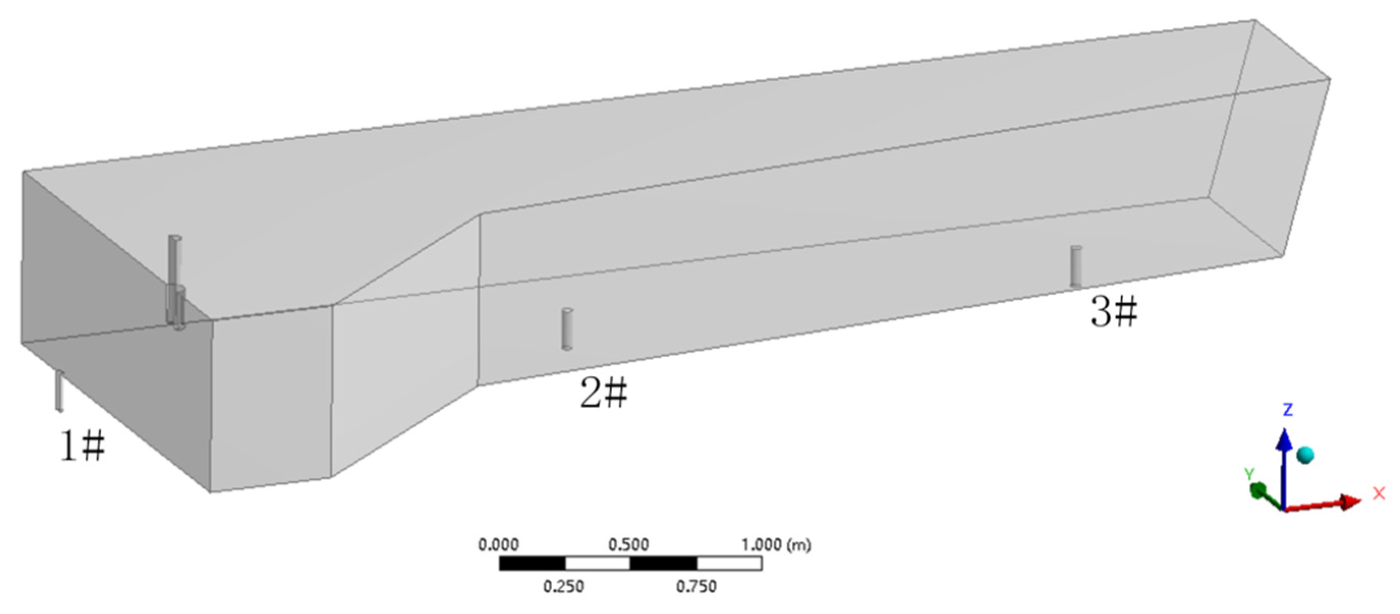
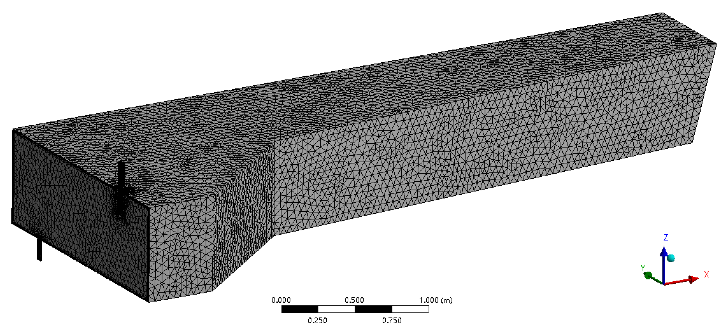
3. Grid and Boundary Conditions
3.1. Model Grid
3.2. Boundary Condition
- (1)
- Inlet boundary condition:
- (2)
- Outlet boundary condition:
- (3)
- Wall boundary condition:
- (4)
- Symmetric boundary:
4. Numerical Simulation of Adding a Porous Baffle Wall
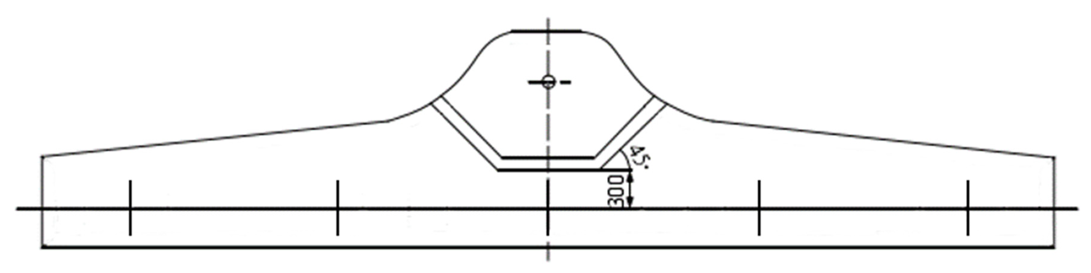
4.1. Structural Design
- (1)
- Shape:
- (2)
- Hole number:
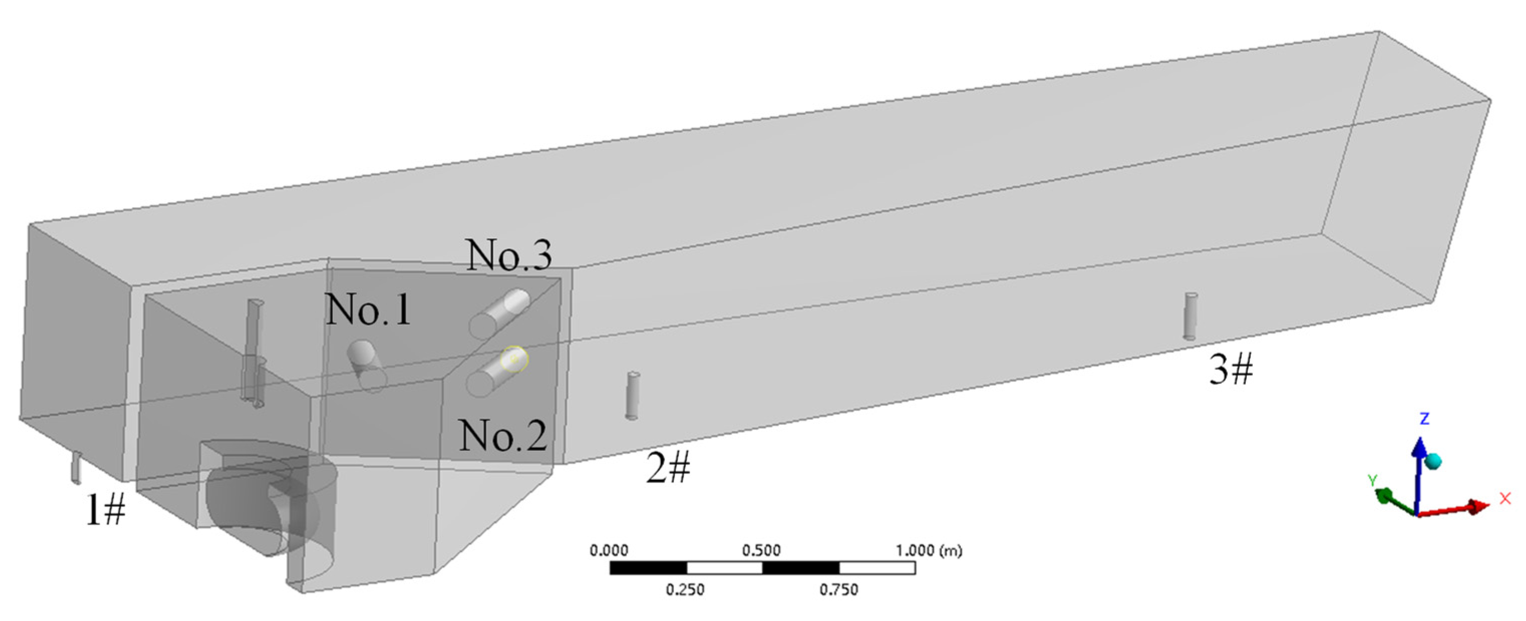
- (3)
- Hole position:
- (4)
- Hole diameter:
- (5)
- Hole inclination angle:
4.2. Orthogonality Design Plan
4.3. Orthogonal Analysis Results
- (1)
- The left inclination angle α1 of the first hole has a significant effect on the comprehensive standard deviation of start response time and average residence time. The left angle α1 controls the flow of molten steel near outlets 1# and 2#. Because the first hole is located between outlets 1# and 2#, the molten steel from the diversion hole flows directly from the molten steel surface to these two outlets. Therefore, when the left angle α1 becomes large, the first hole is closer to outlet 1# outlet, and shortening the distance between them will shorten the starting response time of the molten steel at the corresponding outlet. At the same time, the increase in the left angle α1 will incline the flow direction of molten steel more toward outlet 1# and increase the standard deviation of the average residence time of the three outlets, which is not conducive to the flow consistency of molten steel.
- (2)
- The right angle α2 of the second and third holes mainly regulates the flow in the relevant area of distal outlet 3#. In order to ensure that the molten steel can also maintain flow consistent with outlets 1# and 2# at the farthest end, it is necessary to guide the molten steel in the injection area to the distal end of the tundish with the right angle α2. With increases in the right angle α2, the standard deviation of average residence time decreases gradually and the consistency of each flow is greatly improved. However, when α2 is too large, it will also cause excessive flow to the distal end of molten steel and make the flow of outlets 1# and 2# become worse; therefore, it is important that the right angle α2 has the appropriate value.
- (3)
- With increases in aperture d, the flow control effect of the diversion hole will be weakened, which is not conducive to improving the flow consistency of molten steel. When aperture is at the minimum level, the comprehensive standard deviation of average residence time is small and flow consistency is good.
- (4)
- Increases in elevation angle β will prolong the flow path and residence time of molten steel, but the effect is not obvious. By analyzing the average residence time of each outlet, it can be clearly seen that the average residence time of outlet 3# is no longer greater than the theoretical residence time, and the average residence time of outlets 1# and 2# is significantly increased, which is the interaction between the elevation angle β and the horizontal inclination angles α1 and α2.
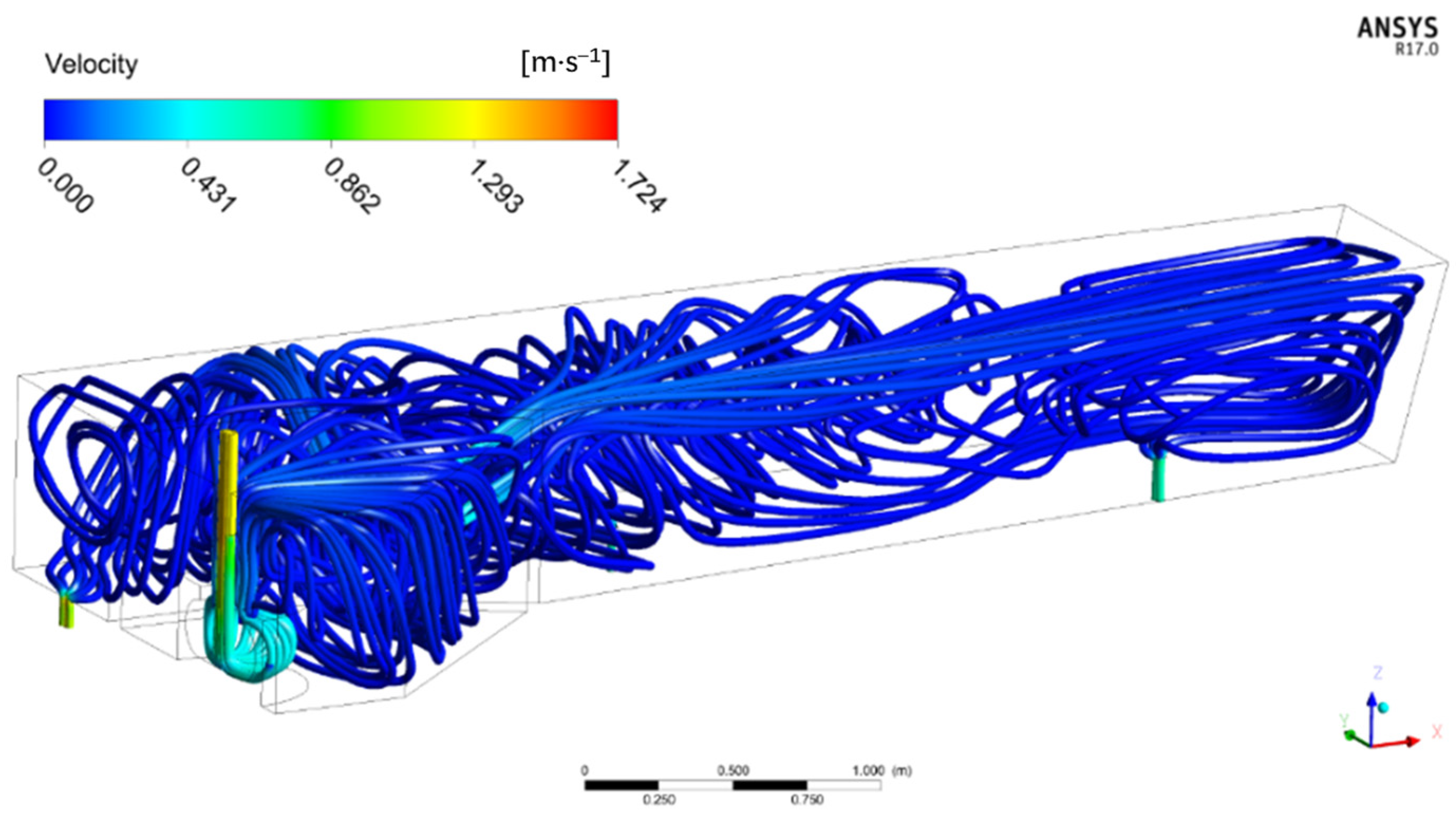
4.4. Flow Field of the Tundish
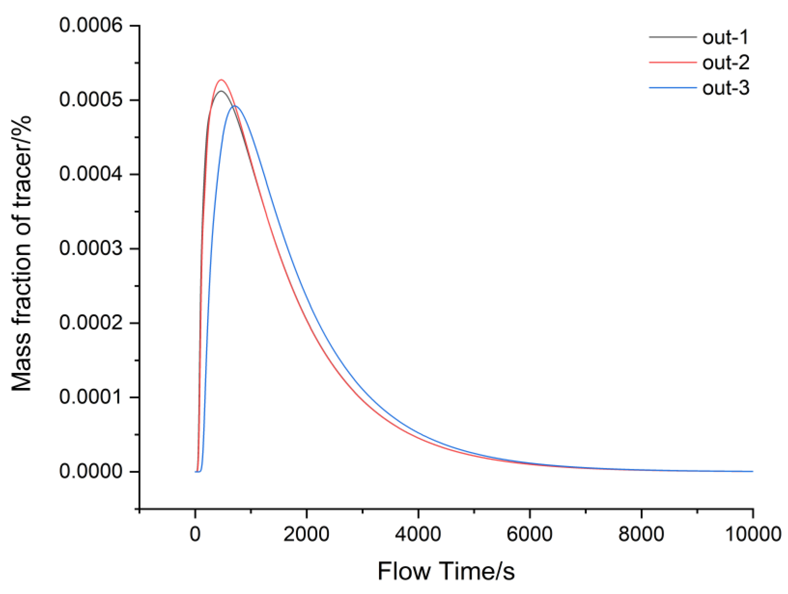
4.5. Residence Time Distribution Curve of the Tundish
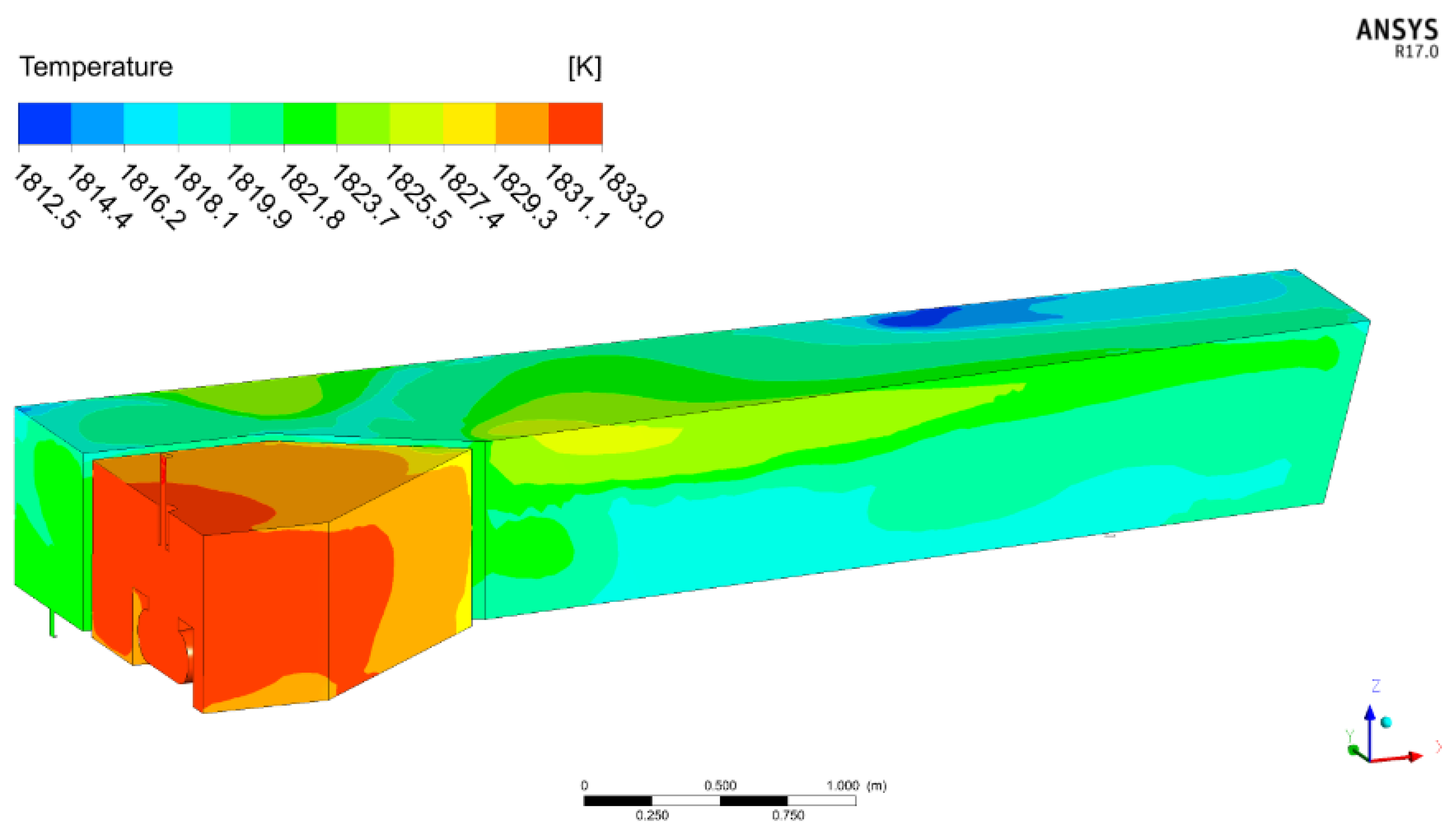
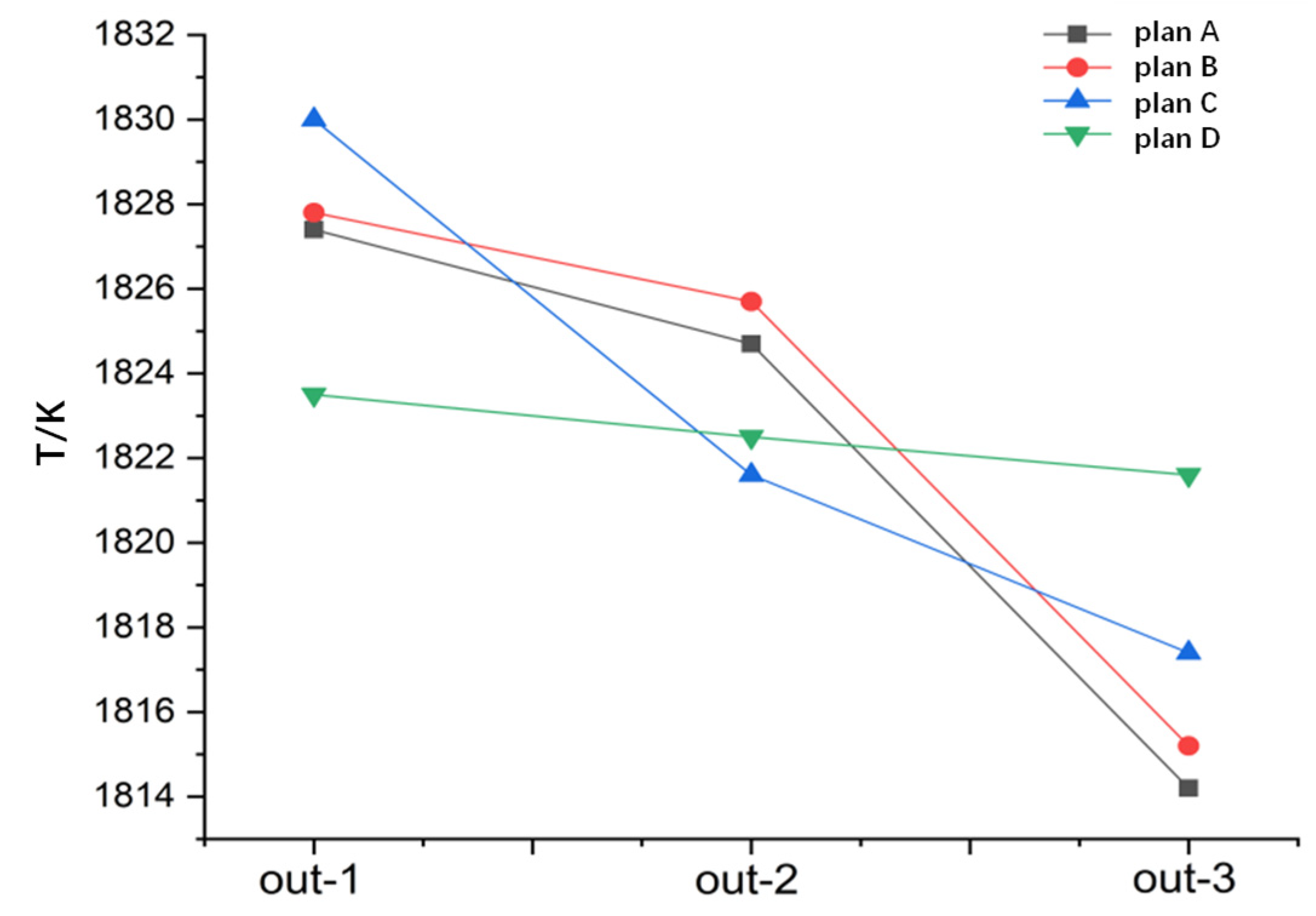
4.6. Temperature Field of the Tundish
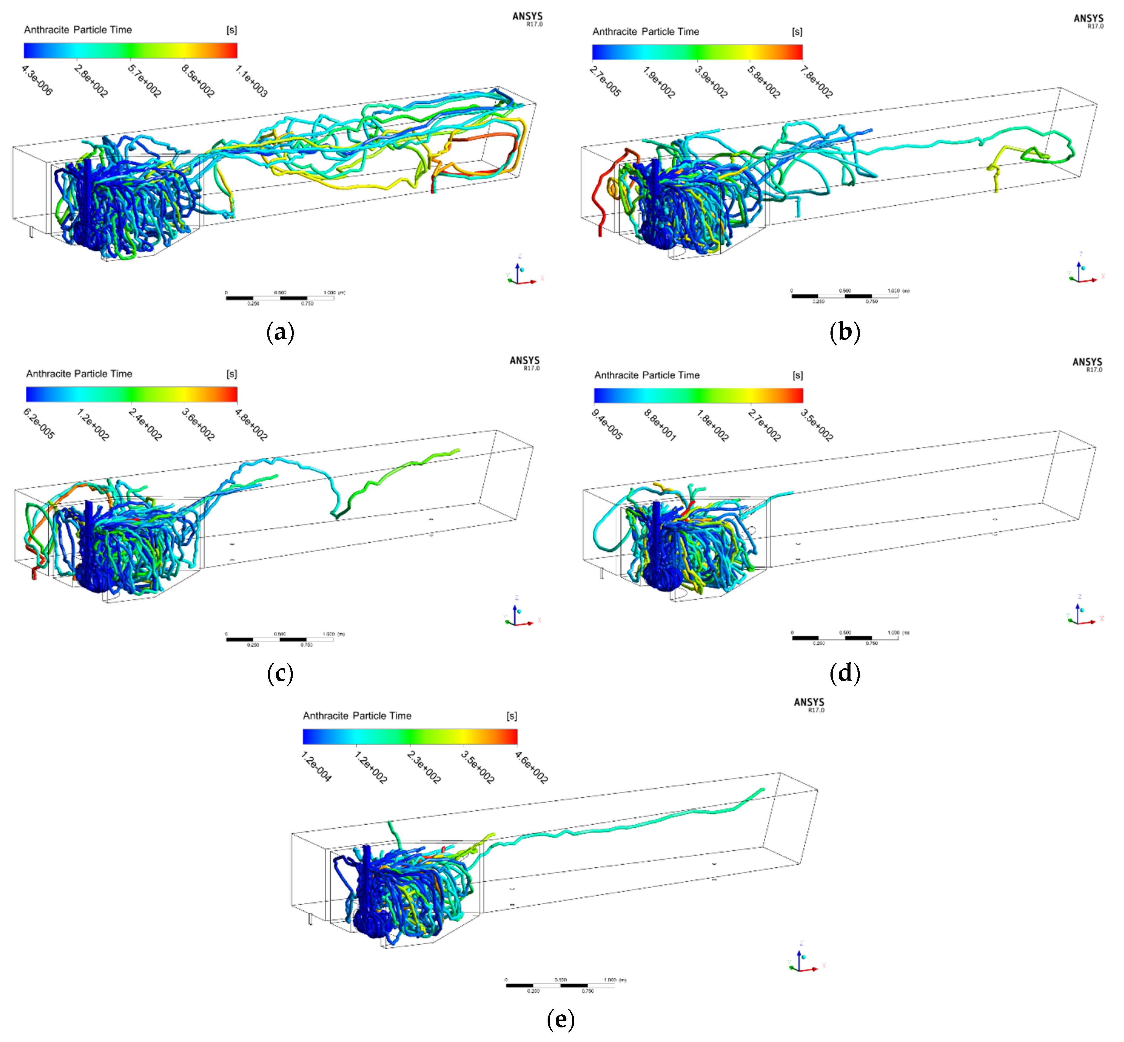
4.7. Simulation of Inclusion Removal
5. Conclusions
- (1)
- Compared to before optimization, the uniformity of the temperature field in the tundish was significantly improved by 61.8%, and the flow field of each strand tended to be consistent. The maximum tundish temperature difference was 21 K, and the maximum temperature difference for the three outlets was only 1.7 K. The dead zone volume was 10.0% less than that of the original tundish, and piston zone volume was increased by 14.2%.
- (2)
- The porous baffle wall structure was optimized according to an orthogonal experimental design, and the optimal scheme of baffle wall holes was scientifically analyzed. Finally, the baffle wall opening plan with a left inclination angle of α1 = 22°, right inclination angle of α2 = 48°, upper elevation angle of β = 30°, and aperture of d = 70 mm was selected.
- (3)
- The removal rate of Al2O3 inclusions of less than 100 μm in the tundish was calculated. Because there were many problems in terms of the flow of molten steel in the original tundish, the removal rate of inclusions was not high. The inclusion removal effect of the circular turbulence controller and baffle wall was very obvious. The removal rates of inclusions of all sizes were maintained at more than 80%, and the removal rate of 70 μm and 90 μm inclusions was 98%.
Author Contributions
Funding
Conflicts of Interest
References
- Zhao, P.; Zhang, H.; Fang, Q.; Wang, J.H.; Wu, G.L.; Ni, H.W. Numerical study on strand-blocking operation of a six-strand square billet tundish. J. Iron Steel Res. 2022, 34, 438–450. [Google Scholar]
- Neumann, S.; Asad, A.; Schwarze, R. Numerical simulation of an industrial-scale prototypical steel melt tundish considering flow control and cleaning strategies. Adv. Eng. Mater. 2020, 22, 1900658. [Google Scholar] [CrossRef] [Green Version]
- De Sousa, R.J.R.; De Souza, E.E.B.; Marcondes, F.B.; De Castro, J.A. Modeling and computational simulation of fluid flow, heat transfer and inclusions trajectories in a tundish of a steel continuous casting machine. J. Mater. Res. Technol. 2019, 8, 4209–4220. [Google Scholar] [CrossRef]
- Li, E.L.; Feng, K.F.; Guo, H.R.; Sun, J.P.; Zhang, J.Y.; Wang, B. Structure optimization of multi-strand transition piece. J. Iron Steel Res. 2022, 33, 943–951. [Google Scholar]
- Lu, H.B.; Zhong, Y.B.; Ren, Z.M.; Ren, W.L.; Cheng, C.G.; Lei, Z.S. Numerical simulation of EMS position on flow, solidification and inclusion capture in slab continuous casting. J. Iron Steel Res. Int. 2022, 29, 1807–1822. [Google Scholar] [CrossRef]
- Dong, Q.P.; Zhang, J.M.; Yin, Y.B.; Nagaumi, H. Numerical simulation of macrosegregation in billet continuous casting influenced by electromagnetic stirring. J. Iron Steel Res. Int. 2022, 29, 612–627. [Google Scholar] [CrossRef]
- Chen, C.; Jonsson, L.T.I.; Tilliander, A.; Cheng, G.G.; Jönsson, P.G. A mathematical modeling study of tracer mixing in a contin-uous casting tundish. Metall. Mater. Trans. B 2015, 46, 169–190. [Google Scholar] [CrossRef]
- Chen, C.; Jonsson, L.T.I.; Tilliander, A.; Cheng, G.G.; Jönsson, P.G. A mathematical modeling study of the influence of small amounts of KCl solution tracers on mixing in water and residence time distribution of tracers in a continuous flow reactor metallurgical tundish. Chem. Eng. Sci. 2015, 137, 914–937. [Google Scholar] [CrossRef]
- Chen, C.; Ni, P.Y.; Jonsson, L.T.I.; Tilliander, A.; Cheng, G.G.; Jönsson, P.G. A model study of inclusions deposition, macro-scopic transport, and dynamic removal at steel-slag interface for different tundish designs. Metall. Mater. Trans. B 2016, 47, 1916–1932. [Google Scholar] [CrossRef]
- Fan, J.; Li, Y.; Chen, C.; Ouyang, X.; Wang, T.; Lin, W. Effect of uniform and non-uniform increasing casting flow rate on dispersion and outflow percentage of tracers in four strand tundishes under strand blockage conditions. Metals 2022, 12, 1016. [Google Scholar] [CrossRef]
- Holzinger, G.; Thumfart, M. Flow interaction in continuous casting tundish due to bubble curtain operation. Steel Res. Inter. 2019, 90, 1800642. [Google Scholar] [CrossRef]
- Cwudzinski, A. Physical and mathematical modeling of bubbles plume behaviour in one strand tundish. Metall. Res. Technol. 2018, 115, 2017081. [Google Scholar] [CrossRef]
- Chang, S.; Zou, Z.; Li, B. Modeling inclusion removal when using micro-bubble swarm in a full-scale tundish with an impact pad. Metall. Mater. Trans. 2022, 53, 526–536. [Google Scholar] [CrossRef]
- Zhuang, Y.L.; Zhuo, C.; Hao, X.S.; Liu, T.; Sun, Y.H.; Zhang, M. Effect of sulfur content on non-metallic inclusions of heavy rail steel. Sci. J. Iron Steel Res. 2022, 34, 799–806. [Google Scholar]
- Sasai, K. Effect of oxygen and sulfur in molten steel on the agglomeration property of alumina inclusions in molten steel. ISIJ Inter. 2018, 58, 469. [Google Scholar] [CrossRef] [Green Version]
- Li, W.; Jin, Y.; Fang, K.Y. Mathematical model of flow field in tundish with square shape swirl type turbulence inhibitor. Foundry Technol. 2018, 39, 34–37. [Google Scholar]
- Wang, L.T.; Zhang, Q.Y.; Li, Z.B. Study on liquid metal flow and impurity removal inside tundish. Steelmaking. 2005, 21, 26–29. [Google Scholar]
- Liu, G.M.; Bi, X.G.; Jin, Y. Simulation of the inclusion movement in the tundish of slab casting. Foundry Technol. 2011, 5, 684–687. [Google Scholar]
- Launder, B.E.; Spalding, D.B. The numerical computation of turbulent flows. Comput. Methods Appl. Mech. Eng. 1974, 3, 269–289. [Google Scholar] [CrossRef]
- Launder, B.E.; Spalding, D.B. Mathematical Models of Turbulence; Academic Press Inc.: London, UK, 1972. [Google Scholar]
- Janiszewski, K. Refining of liquid steel in a tundish using the method of filtration during its casting in the CC machine. Arch. Metall. Mater. 2013, 2, 513–521. [Google Scholar] [CrossRef] [Green Version]
- Chang, Z.S. Physical Simulation Study about the Effects of the Double-Baffle with Refractory Fillers on Flow Field in Tundish. Master’s Thesis, Wuhan University Science and Technology, Wuhan, China, 2016. [Google Scholar]
- Zhong, L.C.; Zhang, L.; Huang, Y.W.; Yang, S.B.; Zhu, Y.X.; Jiang, M.F. Influence of various turbulence inhibitor on fluid flow behavior in tundish. J. Iron Steel Res. 2002, 14, 6–9. [Google Scholar]
- Chen, D.F.; Hu, R.; Wang, Q.X.; Jin, X.; Yan, X.J.; Li, J.Z.; Zhou, K.C. Physical and mathematical study on weir setting in continu-ous casting tundish. Chin. J. Process Eng. 2008, 8, 49–53. [Google Scholar]
- Li, G.Q.; Fu, Y.; Chen, X.H.; Zhang, Z.; Rao, J.P.; Yang, Z.Z. Physical simulation of fluid field and structure optimization in two-strand tundish. J. Chongqing Univ. 2015, 2, 34–37. [Google Scholar]
- Ge, Y.Y. Simulation Research on Flow Field Optimization and Inclusion Removal in Continuous Casting Tundish for Heavy Rail Steel. Master’s Thesis, Hebei University of Engineering, Handan, China, 2020. [Google Scholar]
- Meijie, Z.; Huazhi, G.; Ao, H.; Hongxi, Z.; Chengji, D. Numerical simulation and industrial practice of inclusion removal from molten steel by gas bottom-blowing in continuous casting tundish. J. Min. Metall. 2011, 2, 137–147. [Google Scholar] [CrossRef]


| Parameters | Values | Parameters | Values |
|---|---|---|---|
| Inlet diameter, mm | 65 | Speed, m·min−1 | 0.5 |
| Outlet diameter, mm | 40 | Steel density, kg·(m³)−1 | 7100 |
| Strand spacing, mm | 2096 | Steel viscosity, Pa·s | 0.0062 |
| Immersion depth, mm | 150 | Thermal conductivity, W·(m·K)−1 | 740 |
| Liquid level, mm | 680 | Specific heat capacity, J·(kg·K)−1 | 41 |
| Slab size, mm | 380 × 280 | Inclusion density, kg·(m³)−1 | 5000 |
| No. | Left Angle α1/° | Right Angle α2/° | Vertical Angle β/° | Hole Size d/mm |
|---|---|---|---|---|
| 1 | 22 | 40 | 20 | 70 |
| 2 | 30 | 44 | 25 | 70 |
| 3 | 38 | 48 | 30 | 70 |
| 4 | 46 | 52 | 35 | 70 |
| 5 | 46 | 48 | 25 | 80 |
| 6 | 38 | 44 | 20 | 80 |
| 7 | 30 | 40 | 35 | 80 |
| 8 | 22 | 52 | 30 | 80 |
| 9 | 22 | 48 | 35 | 90 |
| 10 | 30 | 52 | 20 | 90 |
| 11 | 38 | 40 | 25 | 90 |
| 12 | 46 | 44 | 30 | 90 |
| 13 | 46 | 40 | 30 | 100 |
| 14 | 38 | 52 | 35 | 100 |
| 15 | 30 | 48 | 20 | 100 |
| 16 | 22 | 44 | 25 | 100 |
| 17 | 30 | 44 | 35 | 100 |
| 18 | 30 | 52 | 30 | 100 |
| 19 | 46 | 52 | 25 | 100 |
| 20 | 46 | 52 | 20 | 100 |
| No. | t1/s | t2/s | t3/s | tavg/s | tmin/s | S |
|---|---|---|---|---|---|---|
| 1 | 1576 | 1569 | 1775 | 1644 | 64 | 95.6 |
| 2 | 1535 | 1541 | 1841 | 1646 | 57 | 138.2 |
| 3 | 1541 | 1627 | 1765 | 1644 | 62 | 92.3 |
| 4 | 1496 | 1677 | 1762 | 1645 | 59 | 110.9 |
| 5 | 1464 | 1662 | 1751 | 1646 | 56 | 120.0 |
| 6 | 1448 | 1624 | 1869 | 1647 | 61 | 172.6 |
| 7 | 1499 | 1618 | 1814 | 1644 | 59 | 129.9 |
| 8 | 1541 | 1641 | 1753 | 1645 | 63 | 86.6 |
| 9 | 1561 | 1581 | 1771 | 1644 | 68 | 89.6 |
| 10 | 1562 | 1665 | 1662 | 1648 | 71 | 52.6 |
| 11 | 1494 | 1576 | 1896 | 1646 | 65 | 178.5 |
| 12 | 1534 | 1612 | 1790 | 1645 | 67 | 107.2 |
| 13 | 1470 | 1612 | 1856 | 1646 | 65 | 159.4 |
| 14 | 1430 | 1623 | 1884 | 1646 | 57 | 186.0 |
| 15 | 1603 | 1608 | 1831 | 1646 | 65 | 137.8 |
| 16 | 1539 | 1521 | 1874 | 1645 | 55 | 176.5 |
| 17 | 1509 | 1655 | 1765 | 1643 | 67 | 104.9 |
| 18 | 1480 | 1614 | 1844 | 1646 | 53 | 150.3 |
| 19 | 1495 | 1795 | 1662 | 1647 | 48 | 135.1 |
| 20 | 1458 | 1822 | 1662 | 1647 | 47 | 149.0 |
Disclaimer/Publisher’s Note: The statements, opinions and data contained in all publications are solely those of the individual author(s) and contributor(s) and not of MDPI and/or the editor(s). MDPI and/or the editor(s) disclaim responsibility for any injury to people or property resulting from any ideas, methods, instructions or products referred to in the content. |
© 2023 by the authors. Licensee MDPI, Basel, Switzerland. This article is an open access article distributed under the terms and conditions of the Creative Commons Attribution (CC BY) license (https://creativecommons.org/licenses/by/4.0/).
Share and Cite
Zhao, S.; Zhu, S.; Ge, Y.; Wang, J.; Xu, D.; Li, Z.; Chen, C. Simulation of Fluid Flow and Inclusion Removal in Five-Flow T-Type Tundishes with Porous Baffle Walls. Metals 2023, 13, 215. https://doi.org/10.3390/met13020215
Zhao S, Zhu S, Ge Y, Wang J, Xu D, Li Z, Chen C. Simulation of Fluid Flow and Inclusion Removal in Five-Flow T-Type Tundishes with Porous Baffle Walls. Metals. 2023; 13(2):215. https://doi.org/10.3390/met13020215
Chicago/Turabian StyleZhao, Shuo, Shibin Zhu, Yangyang Ge, Jianfeng Wang, Dong Xu, Zushu Li, and Chao Chen. 2023. "Simulation of Fluid Flow and Inclusion Removal in Five-Flow T-Type Tundishes with Porous Baffle Walls" Metals 13, no. 2: 215. https://doi.org/10.3390/met13020215