It is well known that the weld joints produced by FSW have four different zones, specifically the stirring zone (SZ); the thermo-mechanically affected zone (TMAZ), which is caused by the higher temperature and lower strain that occurs during FSW processing; the heat affected zone (HAZ); and the unaffected zone, which is known as the parent metal (PM) or base metal (BM). Specimens welded by the FSW process have HAZs smaller than the specimens joined by fusion welding. For instance, tungsten arc welding was reported to produce HAZs with great widths due to the relatively high heat input [
71,
72], which may result in the failure of joints created by fusion welding [
73]. Comparatively, FSW generates lower heat in the HAZ. Therefore, FSW is preferred for joining steel grades sensitive to thermal cycles rather than fusion welding techniques [
74]. Moreover, FSW refines the grain size in the SZ because of the severe plastic deformation carried out by the stirring tool [
75], which significantly affects the strength, ductility, and toughness of the FSW joints [
76]. On the one hand, during the FSW processes, C and Cr atoms were diffused through the weld metal; consequently, C/Cr-rich regions and depleted zones were formed. This may negatively affect the mechanical properties of the welded joints due to the inhomogeneous distribution of the chemical composition [
77,
78]. On the other hand, because of the tempered martensite formation and the refined austenite in the SZ, FSW specimens showed higher tensile strength than the specimens joined by activated-gas tungsten arc welding of 9Cr–1Mo and 316LN stainless steel [
72].
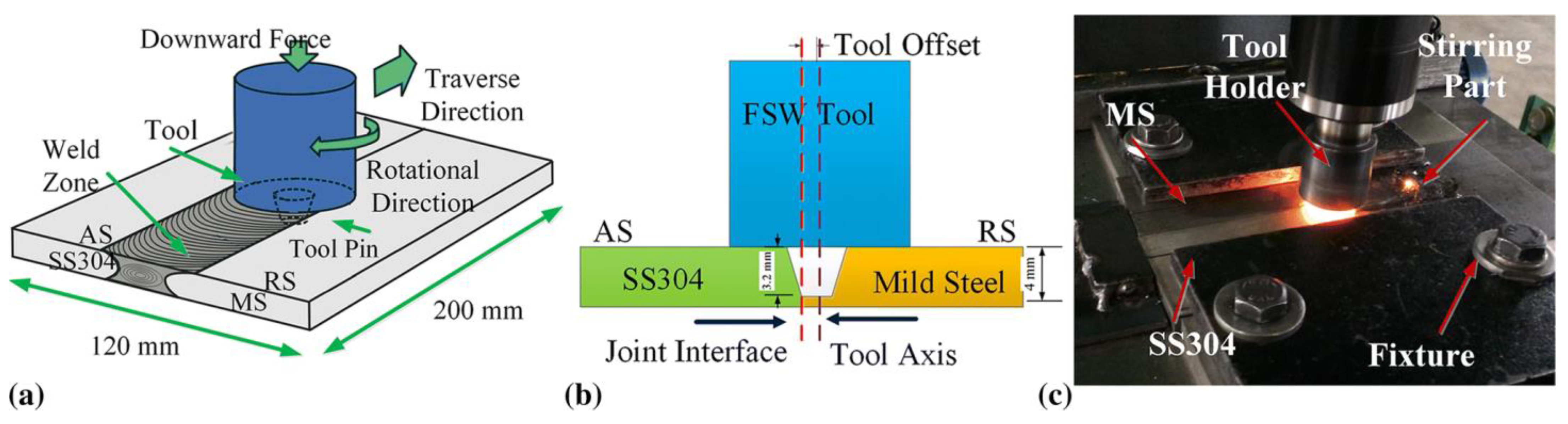
The FSW process is carried out by a stirring tool that rotates between two fixed sheets or plates as butt or lap joints [
79,
80]. The circular tool is a non-consumable tool that rotates against the sheet/plate surface under the effect of an axial load. The tool contains a shoulder and a solid surface or threaded cylindrical pin that heats the workpiece [
76]. The rotating tool is fixed in a chuck on the headstock of a milling machine or any indigenously built FSW machine. The tool geometry, travel speed, and rotational speed of the tool during FSW, therefore, directly affect the physical, mechanical, and microstructural properties of joints. Thus, increasing the tool travel speed led to lower peak temperatures and a higher strain rate in the WZ [
80]. Increasing the rotational speed resulted in a substantial increase in the SZ peak temperature [
71,
81]. The maximum peak temperature (
T) caused in the SZ during FSW of steels can be estimated by using Equation (1) [
72].
where ω, ϑ, and
Tm are the tool rotational speed (rpm), weld travel velocity (mm.min
−1), and melting temperature of BM, respectively;
K and
α are constants (
K = 0.64 and
α = 0.04).
In the following sections, we report the microstructure evolution and mechanical properties of SZ, TMAZ, and HAZ, as well as welding defects accompanying FSW of similar and dissimilar steels. However, the tool design, material selection, and wear behavior are not included in the present study.
2.2.1. FSW of Similar Steels
Ghosh et al. [
80] studied the lap joints of martensitic steel with high strength via M190 sheets with a 1 mm thickness containing 0.19C-0.47Mn-0.17Si, produced by FSW using diverse cooling rates and heat input. The BM of the welded joints had a martensite microstructure; however, the SZ structure varied according to the cooling rate associated with the welding parameters. A slow cooling rate promoted the formation of a ferrite–pearlite structure, while a rapid cooling rate led to the formation of a martensite structure in the weld zone. Moreover, it was found that the HAZ represents the weakest region of all joints and consists of ferrite structure in addition to slight pearlite quantities, which reduced hardness values compared with the SZ. Consequently, during the shear testing, the welded joints fractured along the HAZ.
Ragab et al. [
84,
85] carried out the FSW of lap joints between martensitic steel sheets with high strength and a thickness of 3.8 mm. The tool used in the FSW process was made of W-25%Re and had a tapered threaded pin with a length of 2.95 mm and a 3 mm tip pin diameter. The traverse speed of the tool was 75 mm/min and was kept constant, the tool rotational speeds ranged between 250 rpm and 650 rpm, and the SZ was basin-shaped. Their results revealed that the BM microstructure consists of quenched martensite laths with small amounts of M23C6 carbides. Moreover, the peak temperature was achieved at a rotational speed of 550 rpm; therefore, the required temperature for transforming austenite to delta ferrite was reached. The width of the HAZ increased with the increase in the tool’s rotational speed. The microstructure of the SZ was recrystallized dynamically, and the fine martensite laths were formed. The M23C6 carbides disappeared in the SZ. At 250 rpm in the SZ, the grain size of the prior austenite grain was 43% of the BM, and the size of martensite was about 68% of the BM. A further increase in the speed of the tool to 550 rpm resulted in an additional increase in prior austenite and martensite to 68% and 87% of the BM, respectively. The grain refinement was attributed to the CDRX effect. Furthermore, the SZ and TMAZ recorded the greatest values of the average hardness and rose 20% to 25% compared to the hardness of BM. However, the lowest hardness values were recorded in the HAZ, and they were 80% at the lowest rpm and 75% at the highest rpm compared to the BM.
Further increase in tool rotation to 650 rpm resulted in the fill lack defect due to excessive heat input. At high temperatures, the steel at the weld surface showed a tendency toward decohesion. Therefore, the tool shoulder was insufficient to form and constrain the plasticized weld metal.
Wang et al. [
74] performed FSW on the lap joint of DP1180 (dual-phase structures of martensite and ferrite) with three different tool-tip diameters (0.2, 0.4, and 0.8 mm) at 400 rpm and a 150 mm/min traverse speed. The composition of the used DP1180 steel is presented in
Table 1. The findings showed that the microstructure consisted of a typical dual-phase structure of martensite and ferrite. The tempered martensite phase formed in the SZ because the temperature during the FSW exceeded the Ac3. The stability of the present phases in the HAZ was slightly affected by the increasing temperature since it showed the existence of the tempered martensite phase, which was surrounded by fine ferrite. The tempered martensite and soft ferrite formation were the major reason for hardness reduction in the HAZ. The HAZ was subdivided into three zones according to the size of the ferrite phase. The further the distance from the stirring zone, the larger the ferrite size. Additionally, they reported that when the stirring pin was increased from 0.4 to 0.8 mm, the joint shear strength was decreased due to the formation of intermittent veins as the material was piled slightly on the surface of the rear weld.
Wang et al. [
86,
87] studied the weldability of quenched and partitioned advanced high-strength 1180 steel via the FSW technique.
Table 2 presents the chemical composition of the QP1180 steel sheets. The sheets had thicknesses of 1.6 mm. FSW was processed at two different rotational velocities, 450 and 600 rpm.
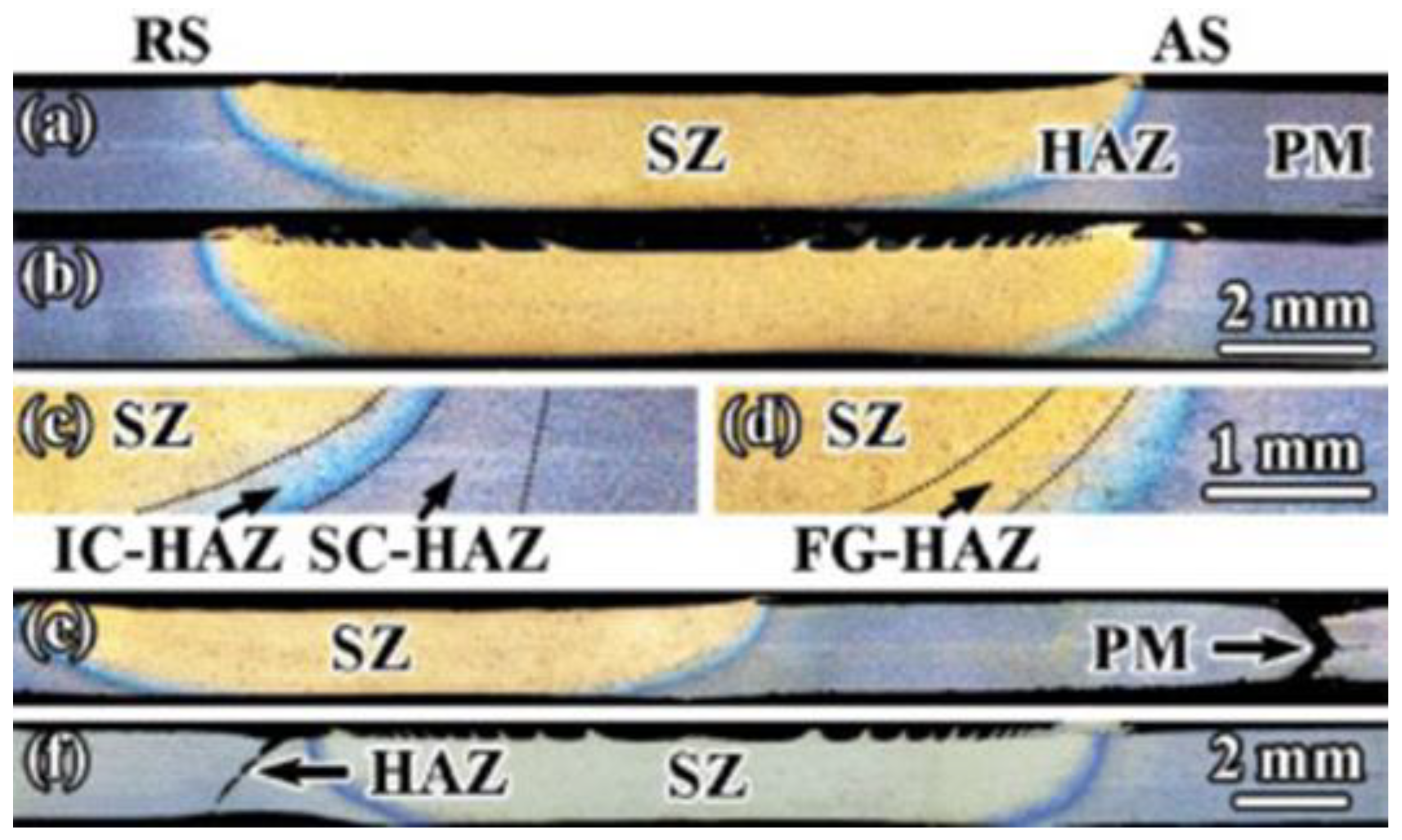
Figure 7 shows three regions of the HAZ at two different rotational velocities. Moving away from the SZ, the HAZ was categorized as fine-grained HAZ (visible only for the welded joints at 600rpm), which was experienced at a temperature that reached Ac3; inter-critical HAZ (IC-HAZ), which was experienced at a temperature that ranged between Ac3 and Ac1; and sub-critical HAZ (SC-HAZ) which was subjected to a temperature below Ac1. It is worth noting that, for this steel, the Ac1 and Ac3 temperatures of phase transformation are 746 °C and 847 °C, respectively [
88]. In addition, the width of the HAZ was improved with the rotational velocity of the stirring tool increase. The PM showed a dual-phase microstructure of ferrite (F) and lath martensite. The SZ showed a microstructure of full martensite. The formed martensite at 600 rpm showed coarser grains compared to that formed at 450 rpm. In addition, the structure of the fine-grained HAZ was like the SZ. The IC-HAZ and SC-HAZ showed a dual-phase structure of martensite and ferrite. In their results, it was found that the HAZ was softer than the SZ and PM. Hardness reduction in HAZs was attributed to the gradual fraction growth of ferrite. The welded joint tensile strengths were equal to the PM, while the ductility decreased. Moreover, joints welded at 600 rpm showed failure during the tension test in the HAZ.
Johnson et al. [
89,
90] investigated the weldability of AISI 321 stainless steel sheets (3 mm thick) via FSW.
Table 3 shows the AISI 321 steel chemical composition. The welding process was conducted at a 55 mm/min traverse speed, 500 and 700 rpm tool rotational rates, 13 KN axial force, and a 1.5° tool tilt angle. It was revealed that the PM exhibited an austenitic structure. In the weld SZ, the microstructural structures exhibit that the evolution of the structure of equiaxed, fine austenite grains was dominated by a discontinuous dynamic recrystallization mechanism. Consequently, the hardness at the SZ was significantly higher compared to the BM hardness.
The maximum microhardness, 245 HV, resulted from welding at a speed of 75 mm/min, which was revealed in the weld SZ. However, the yield strength of the base steel was 320 mPa, and the yield strength of the welded joints was 555 at a welding speed of 500 rpm and 579 mPa at 700 rpm. In addition, the ultimate tensile strength of the welded joints was recorded at 610 mPa at a welding speed of 500 rpm, while the UTS increased to 632 mPa at 700 rpm. The ductility of the weld joints was lower than the BM; however, the dimple structure was detected at the fracture zones.
Kumar et al. [
86] studied the impact of the FSW tool material on the microstructural and mechanical properties of the 316L stainless-steel butt-welded joints.
Table 4 shows the 316L stainless steel chemical composition. The sheets had thicknesses of 1.6 mm each. The study implied the usage of two different tools: a tungsten lanthanum oxide and a tungsten heavy alloy tool. The FSW was carried out using a 600 rpm tool rotational speed and 45 mm/min welding speed. The results showed that the tungsten lanthanum oxide tool produced joints with improved microstructural and mechanical behavior compared to the joints processed by the tool made of the tungsten heavy alloy.
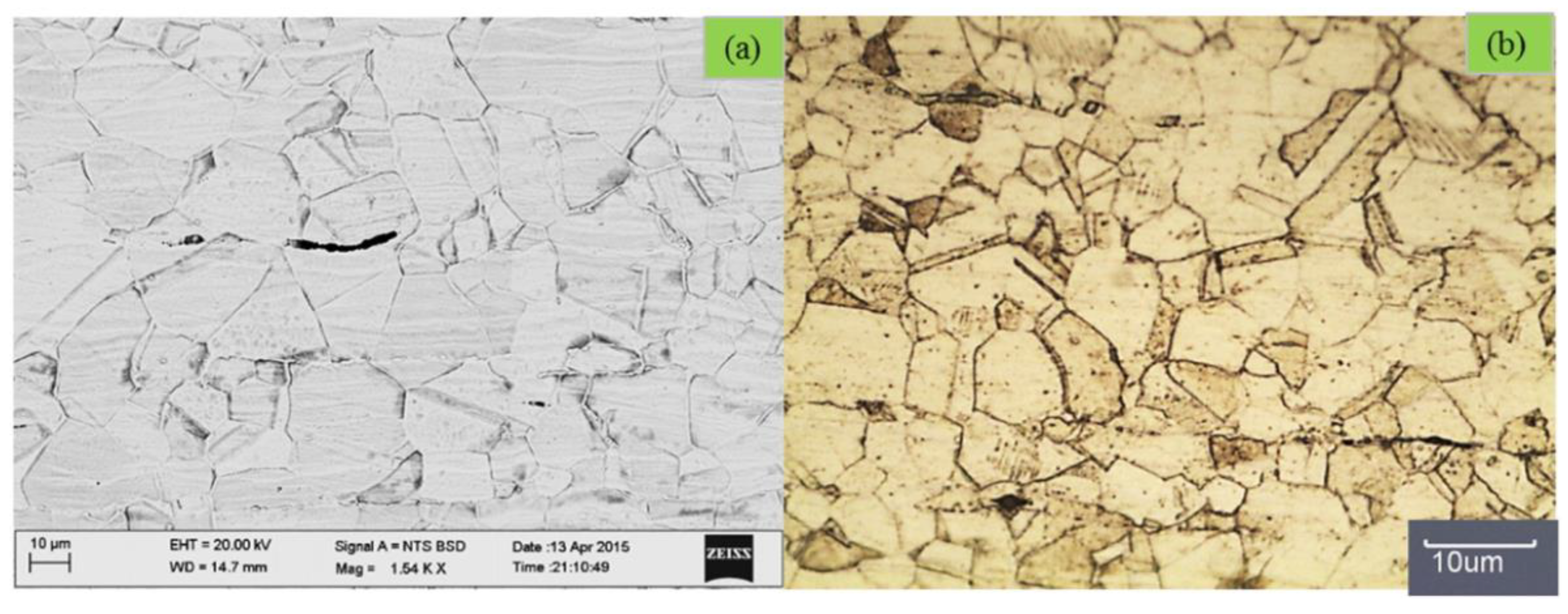
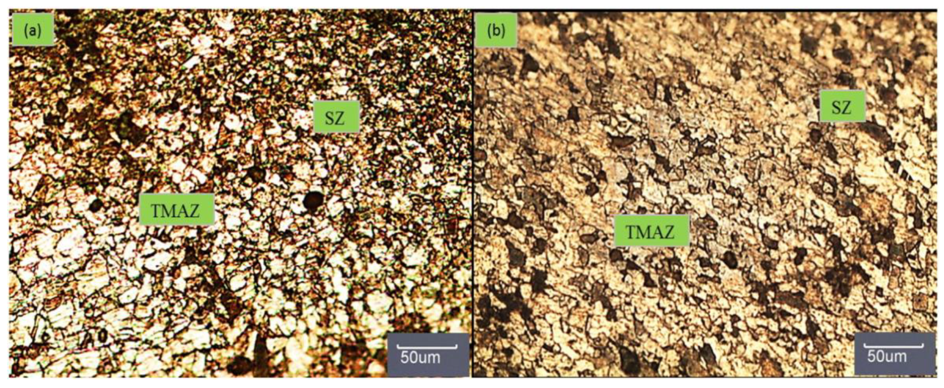
Figure 8 illustrates the optical and SEM micrographs of the 316L BM. The BM showed the existence of an austenite matrix in addition to low amounts of ferrite. In addition, annealing twins were found, at some locations, crossing grain boundaries. In addition, the average grain size was 25 ± 4 μm. However, after the FSW using the tungsten lanthanum oxide tool, in the SZ, roughly equiaxed grains with 7 ± 3 μm average grain sizes were formed, as can be seen in
Figure 9. On the other hand, FSW using the tungsten heavy alloy tool resulted in an appearance of equiaxed and ultra-fine grains with 6 ± 3 μm average grain sizes in the SZ. The sigma phase was not detected in any zone in the interface region of the joint. In addition, the average grain sizes in the TMAZ of joints produced by tungsten lanthanum oxide and tungsten heavy alloy tools were 10 ± 3 and 8 ± 3 μm, respectively. The yield strength of joints produced by both tools was significantly greater than the BM due to the grain refinement in the SZ, as well as the hardness increased across the joint (as shown in
Table 5). The sigma phase was not indicated in either case in any region of the interface joint zone.
Additionally, Ramesh et al. [
92] used the FSW technique to weld 3 mm-thick 316L ASS plates. The microstructure and mechanical behavior of the studied welding conditions were reported. The chemical composition of the investigated 316L ASS plates is listed in
Table 6. In their study, a tungsten alloy (W-Re) tool was utilized for the FSW. Varied traverse speeds were used and ranged from 45 mm/min to 85 mm/min, with a step of 10 mm/min at 500 RPM. No tool wear was recorded [
92]. The findings of their investigation showed that the BM exhibited coarse austenitic grains, as well as several annealing twins inside the grains. The SZ displayed significant grain refinement, as well as XRD confirmation of the presence of delta ferrite phase traces at 45–65 mm/min traverse speeds. The twin plate volume fraction was reduced in the SZ. The grains in the SZ were equiaxed. Moreover, the grain size decreased as the traverse speed increased. Grain refinement occurred due to dynamic recrystallization during FSW. On the other hand, the TMAZ showed slightly elongated grains, and the HAZ showed a similar structure to the PM.
In their study, the PM and SZ showed hardness values of 160 ± 5 and 190 ± 15, respectively. The SZ displayed higher hardness compared to the parent metal under all FSW conditions due to grain refinement. The hardness values increased as the traverse speed increased due to grain size reduction, decreasing the degree of deformation at higher traverse speeds, thus reducing the density of the existing dislocations in the SZ. Moreover, the joint strength and fracture toughness improved with an increase in traverse speed from 45 to 65 mm/min, then decreased because of the existence of root flaws above the 65 mm/min traverse speed. It is worth noting that insignificant root defects existed at the plate at 75 and 85 mm/min traverse speeds, while these defects did not appear at 45, 55, and 65 mm/min traverse speeds.
Sunilkumar et al. [
77,
81] carried out FSW of 9Cr-1Mo steel butt joints at 200 and 500 rpm. Each sheet had a 3 mm thickness. It was found that the BM microstructure of the 9Cr-1Mo steel consisted of tempered martensitic within the prior austenite grain boundary with a 12 ± 2 µm average grain size. It was revealed that, at a 200 rpm tool rotational speed, the peak temperature was lesser than the lower critical transformation temperature (Ac1). Regarding the 200 rpm weld, fine martensite was detected in the SZ, which was attributed to the significant plastic deformation through FSW and the high hardenability of the 9Cr-1Mo steel. Nevertheless, the peak temperature was between Ac3 and Ac1 when using a tool rotational speed of 500 rpm. The SZ showed a typical lath martensitic structure. Using 200 rpm exposed comparatively higher hardness at the SZ (about 20 VHN) compared to 500 rpm, which was attributed to the formation of a fine-grained structure. Their results revealed that the grain size of the base metal was ~12 μm. The distribution of the grain size between the weld SZ matrix of the specimen displayed a finer grain size of ~4 μm at 200 rpm compared to the 500 rpm weld, which was ~5.9 μm. This is attributed to the higher dynamic recrystallization effect at 200 rpm compared to 500 rpm.
Kumar et al. [
93] applied FSW to join 3 mm of AISI 316L stainless steel at butt joints. The AISI 316L stainless steel chemical composition is shown in
Table 7. The FSW tool was made from a tungsten-lanthanum alloy (99% W, 1% La
2O
3). The welding process was conducted at a 600 rpm tool rotational speed, 12 kN axial force, and a 1.5° tool tilt angle. Different welding speeds ranged from 25 mm/min to 100 mm/min, with 25 mm/min increments.
The results revealed that the base steel microstructure demonstrated coarse grains of austenite and minor amounts of ferrite. The base steel had an average grain size of 28 ± 5 μm. The austenitic matrix decreased as the welding speed increased, and the average grain size in the SZ decreased from 142 at 25 mm/min, to 72 at 50 mm/min, and 32 at 75 mm/min. Moreover, the equiaxed grains in the SZ were clearly indicated due to the discontinuous dynamic recrystallization mechanism during FSW. In addition, the highest temperatures in the welded joints were 1164, 975, and 798 °C at 25, 50, and 75 mm/min, respectively. Moreover, low welding speeds resulted in the formation of a delta ferrite phase in the SZ. The delta ferrite delta phase emerged as a thin flake-like structure between the austenite grain boundaries. Additionally, the ferrite phase fraction in the SZ was 7.21 ± 0.45%. However, in the TMAZ, the average grain size produced using different welding speeds of 25, 50, and 75 mm/min was 16 ± 2, 10 ± 2, and 7 ± 2 μm, respectively. Consequently, welding speed significantly impacted the microstructural evolution in the WZ, toughness, and joint strength. The welded joint fracture toughness improved as the welding speed increased. The toughness and tensile strength using a welding speed of 75 mm/min were 49 J/cm2 and 632 MPa, respectively, whereas the toughness and tensile strength of the BM were 50 J/cm2 and 630 MPa, respectively. The BM recorded a hardness value of 190 ± 5 HV. Furthermore, the highest microhardness, 275 HV, was recorded in the SZ when welded using 75 mm/min as the welding speed. Thus, the microhardness at the SZ increased with the increase in welding speed, which was attributed to the growth of fine equiaxed grains. The presence of austenite fine equiaxed grains and the consequent hardness improvement at the SZ caused the superior strength of the joint compared to steel processed at higher welding speeds. However, exceeding the welding speed limit resulted in a lack of material coalescence and plasticization, which led to defects in the internal tunnel.
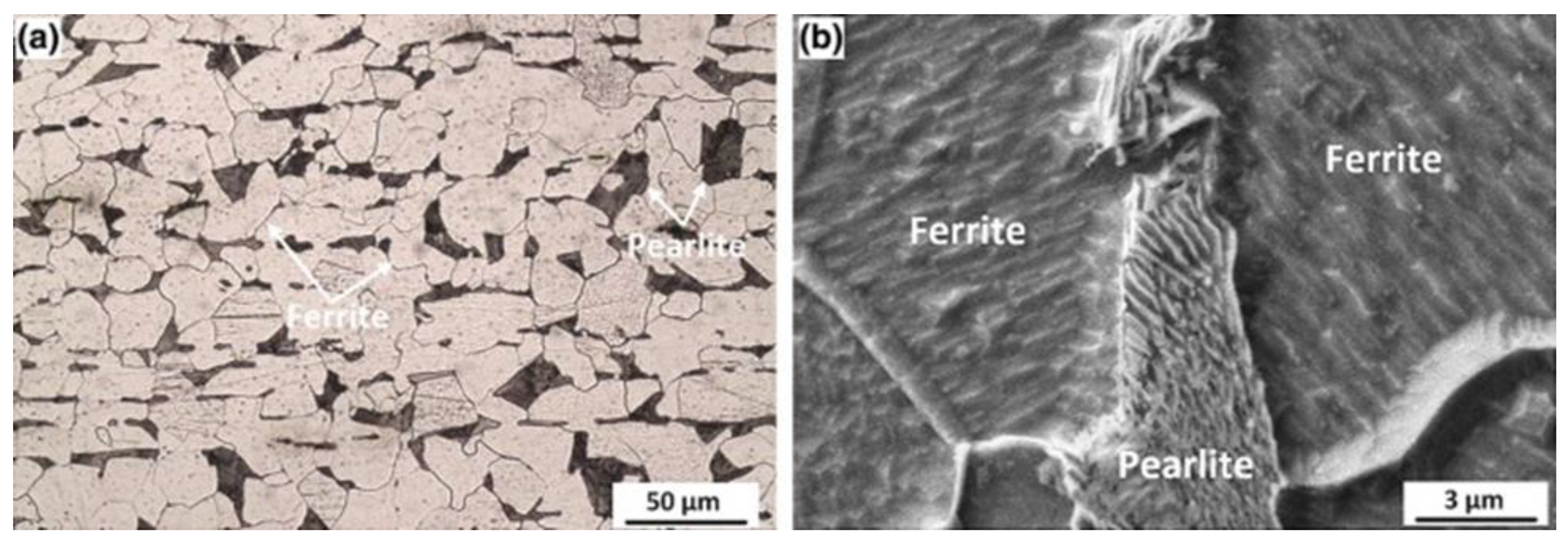
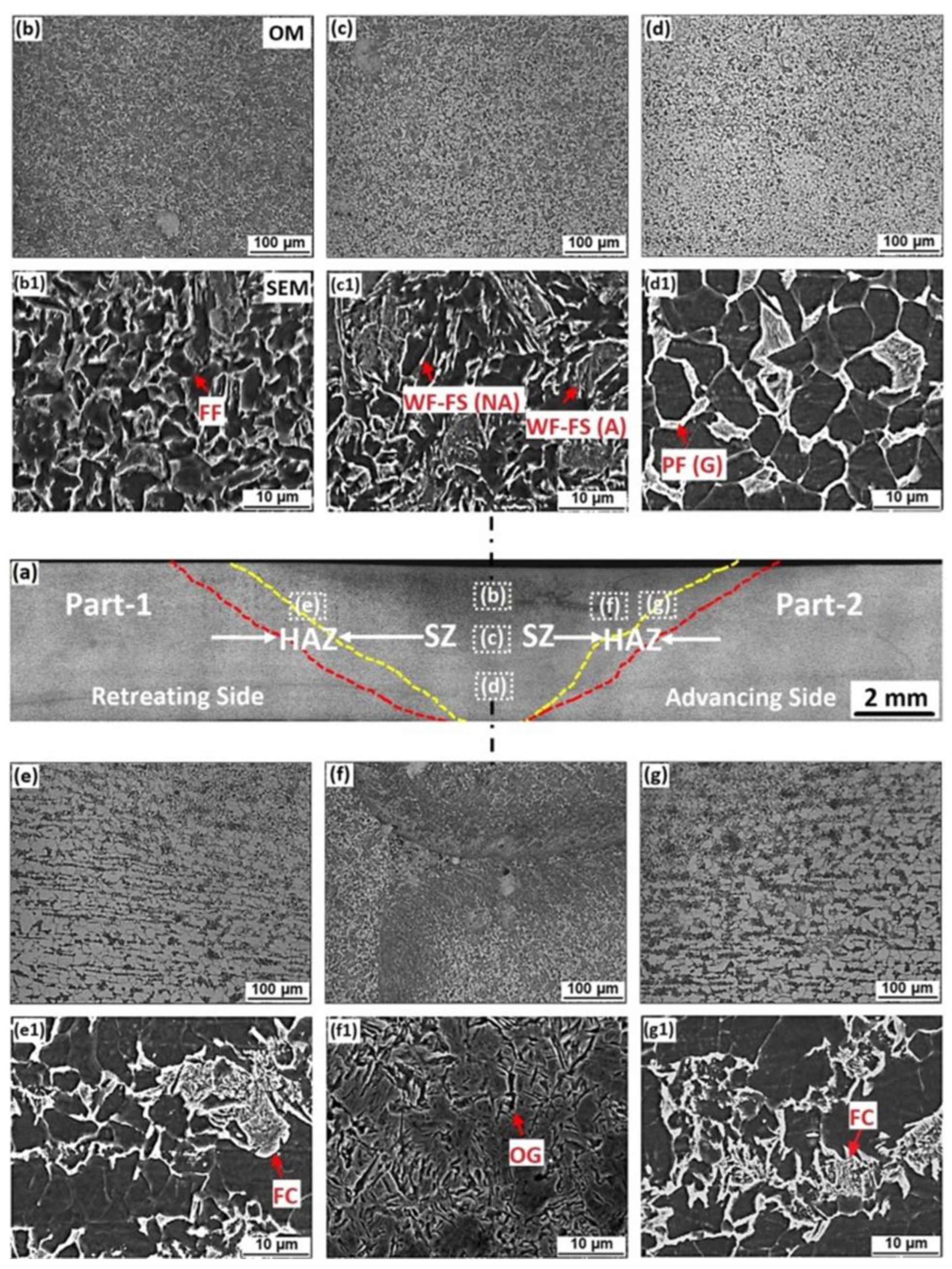
Sekban et al. [
94] joined low-carbon steel plates (ASTM 131A) by FSW. The sheets (4 mm thickness each) contain wt.% of 0.16C-0.18Si, 0.7Mn, 0.11S, 0.18P, 0.09Cr, 0.14Mo, 0.04Cu, 0.04V, and a balance of Fe in their chemical composition. The tool’s rotational speed was 630 rpm, and the traverse speed was 45 mm/minutes. In addition, the tilt angle of the shoulder was 3 deg, with 11 kN of downforce during the FSW process. The results demonstrated that the PM contained coarse grains of ferrite and pearlite phases, and the ferrite phase had an average grain size of about 25 μm, as shown in
Figure 10. Micrographs of the FSWed joint microstructure are presented in
Figure 11. The microstructure of the SZ consisted of an equiaxed fine-grained microstructure because of the dynamic recrystallization. Moreover, the ferritic grain size decreased in the SZ from 25 µm to approximately 4 µm. In addition, during FSW, the SZ temperature was above the A3 temperature line. No martensitic or bainitic transformation occurred in the welding area during the FSW. However, the upper side of the welded zone, which made direct contact with the tool shoulder, showed the existence of martensite and bainite phases because of the higher cooling rate in comparison with the deeper SZ material. The nearest zone of the HAZ to the SZ showed fine-grained ferrite and perlite, while the middle area of the HAZ exposed refined pearlite colonies and a small fraction of the ferrite grains. In addition, the nearest part of the HAZ showed ferrite grains and spheroidized carbide. The differences in the structure of the HAZ are attributed to the variations in the temperature profile during the FSW technique.
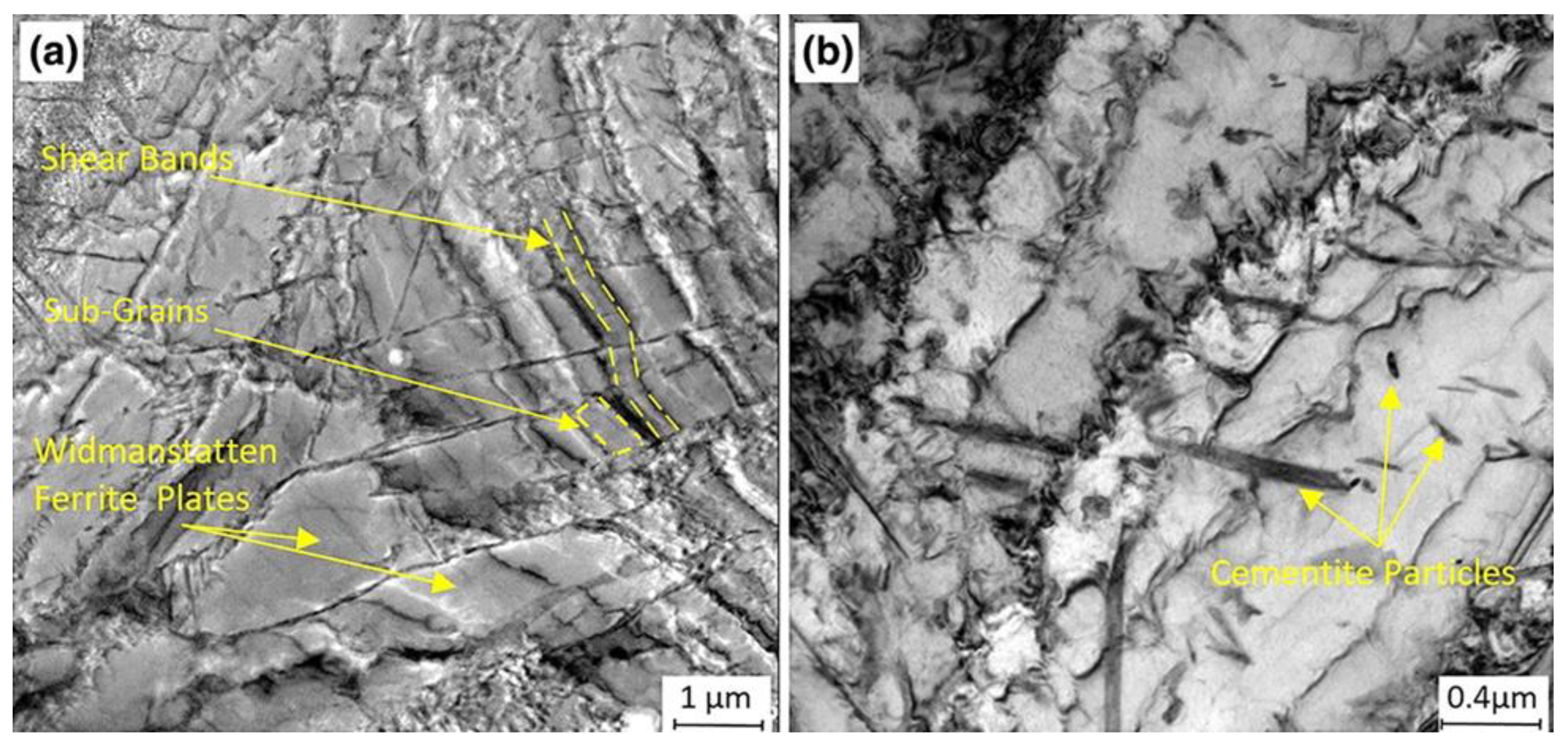
The dynamic recrystallization in the SZ occurred because of the significant plastic deformation; thus, the Widmanstatten ferrite structure generated a moderately low dislocation density. Shear bands of subgrains were perpendicularly oriented to the Widmanstatten ferrite plates because of intensive plastic deformation, as shown in
Figure 12a.
Figure 12b reveals the ferrite-cementite aggregates. The lamellae cementite in the initial microstructure, perlite, is fragmented by the rotating pin stirring effect. Additionally, the SZ hardness rose from 140 to approximately 230 Hv0.3. Moreover, the SZ yield strength increased from 256 to 435 MPa, whereas the tensile strength rose from 457 to 585 mPa without significantly decreasing the ductility.
Kamaraj et al. [
95] joined HSLA steel sheets (3mm thickness each) through FSW. The FSW was carried out by a tungsten-rhenium tool at 500 rpm. The traverse speed was diverse from 57 to 97 mm/min with 10 mm/min in step. In their work, the PM microstructure showed the existence of pearlite and ferrite. During FSW, the peak temperature was greater than the allotropic transformation temperature (A3) at the different traverse speeds (57, 67, and 77 mm/min), while it was lower than 600 °C at 87 and 97 mm/min. Furthermore, the weld nugget microstructure exposed the upper bainite phase and the presence of fine ferrite. The traverse speed reduced the amount of upper bainite, as revealed by EBSD, which can be attributed to the peak temperature decrease and the rapid cooling rate. In addition, the grain size decreased with the transverse speed increase.
The weld nugget exhibited higher hardness than the refined ferrite and bainite phases. However, the hardness decreased with the faster traverse speed, which can be attributed to the bainite structure formation reduction and the soft ferrite phase increase.
Furthermore, the strength of the joint at 57 mm/min was 540 MPa, and at 97 mm/min was 407 MPa. A traverse speed below 78 mm/min resulted in a higher strength because of the hard weld nugget. However, an additional increase in the traverse speed led to lower joint strength, which can be attributed to macroscopic defects and poor consolidation. The macroscopic defect-forming tendency increased with the increase in traverse speed; this resulted in a tensile strength reduction. Groove defects and root flaws were detected at a 97 mm/min traverse speed. In addition, using 97 mm/min as the traverse speed did not pass the root bend test.
2.2.2. FSW of Dissimilar Steels
In this regard, Sauraw et al. [
96] used an FSW technique to join different grades of Cr-Mo steel, modified 9Cr-1Mo: P91, and 2.25Cr-1Mo: P22 for application in a power plant. The chemical compositions of the base plates are presented in
Table 8. The FSW of 2.25Cr-1Mo to 9Cr-1Mo steel was performed on a square butt geometry under 200 and 500 rpm. The ERNiCrMo-3 Ni-based superalloy was utilized as a filler material.
The PM microstructure of the 9Cr-1Mo steel consists of tempered martensitic within prior austenite grain boundaries with an average grain size of 12 ± 2 µm. In contrast, the 2.25Cr-1Mo steel exhibited ferritic–bainitic phases in the microstructure with an average grain size of 15 ± 3 µm. Additionally, in their study, the SZ microstructure revealed the existence of a martensitic structure, and the peak temperature evolution at the SZ was above the Ac1. Hence, tempered martensite/bainitic and the proeutectoid/ferrite structure of 9Cr-1Mo-2.25Cr-1Mo BM were changed to a single-austenite phase during the FSW process heating cycle and then transformed to martensite by the progressive cooling cycle. The EBSD results confirmed the increase in low-angle grain boundaries in the SZ with the rotational speed increase from 200 rpm to 500 rpm due to the increase in the dislocation numbers related to severe plastic deformation from the FSW process. The TMAZ of FSW-processed 2.25Cr-1Mo and 9Cr-1Mo sides revealed a typical lath martensitic structure. The severe plastic deformation associated with FSW induced the martensitic phase transformation while increasing the tool’s rotational speed increased the martensite lath size.
Moreover, the HAZ microstructure of the 9Cr-1Mo side exposed a fine martensitic structure; however, the 2.25Cr-1Mo side of the microstructure consisted of ferrite, bainite, and tempered bainitic structures. The ferrite structure was coarsened with an increase in the rotational speed of the tool from 200 rpm to 500 rpm, which can be attributed to the slow cooling rate at higher heat input. Eventually, the hardness of the SZ, TMAZ, and HAZ of the specimens welded by FSW was higher than other specimens welded by TIG. However, the ductility of the specimens joined by FSW was lower than those welded by TIG after a post-heat treatment was applied. Thus, FSW is not recommended for welding steel grades that require post-weld heat treatments due to the existence of a soft zone and hard zone in the weld zone.
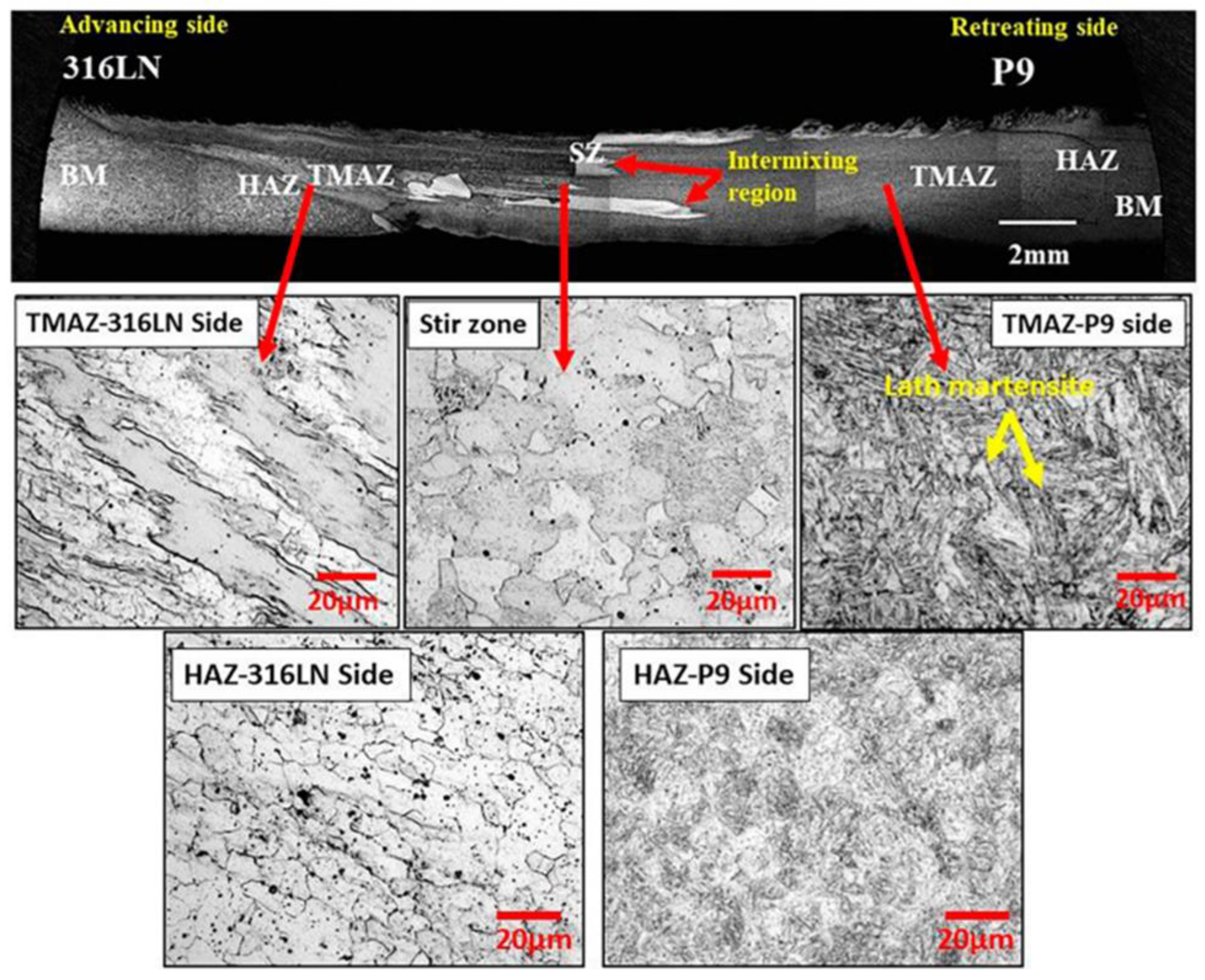
Sunilkumar et al. [
72] investigated the microstructure evolution and mechanical properties of welded 316LN stainless steel to 9Cr–1Mo (P9) steel via FSW. The FSW was performed with a tool rotational speed of 400 and 600 rpm and 3 mm-thick butt joints. It was found that at 600 rpm, tool wear was recognized. The parent metal microstructure of the 9Cr-1Mo steel revealed a tempered, martensitic microstructure within the prior austenite grain boundary; the average grain size was 12 ± 2 µm. The parent metal microstructure of the 316LN SS showed an equiaxed austenitic structure in addition to annealing twins. Furthermore, the average grain size was 23 ± 5 µm.
Figure 13 shows the structure of the joined 9Cr-1Mo and 316LN. The matrix interface (SZ) of the dissimilar weld had a martensitic structure and refined austenite because of dynamic recrystallization. The evolved peak temperature of 9Cr-1Mo steel during the FSW was near the Ac3 temperature, and the 9Cr-Mo side microstructure had lath martensite. Additionally, the austenite deformed grains were detected in the TMAZ of the 316LN side, while the HAZ of the 316LN side showed finer austenitic grains. However, on the 316LN side, the HAZ was four times wider than the HAZ of the 9Cr-1Mo side due to its higher thermal conductivity. Joints produced by FSW showed higher strength and ductility than those produced by TIG. Nevertheless, the HAZ width of the specimens welded by FSW was approximately half the value of the HAZ width of the specimens welded by TIG.
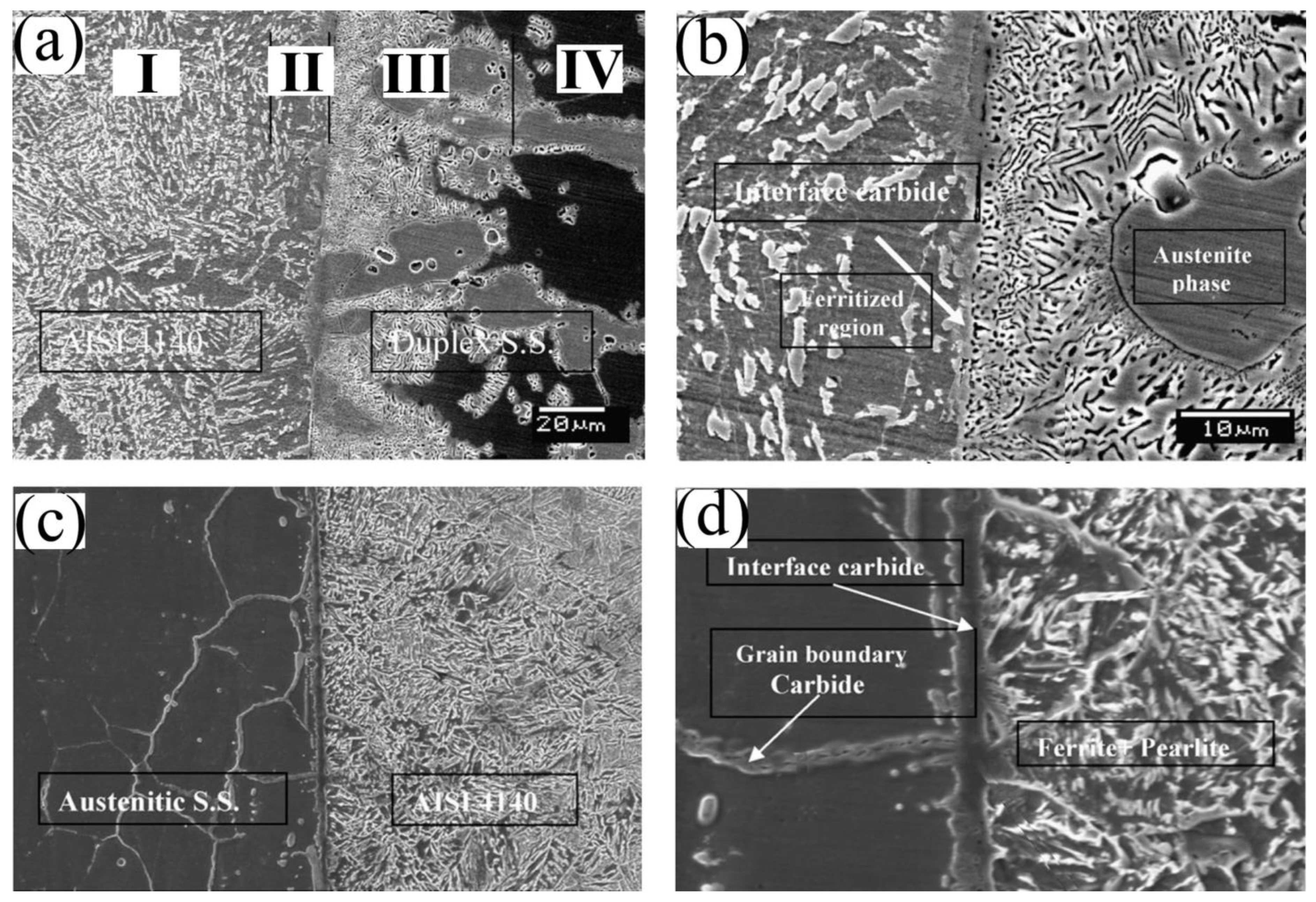
Rahimi et al. [
97] implemented FSW to join 2205 duplex stainless steel to S275 low-carbon–manganese structural steel sheets (butt joints, 6 mm thickness each). The FSW was performed at a tool rotational speed of 200 rpm and 100 mm/min traverse speed, under 55 kN as the average downward axial force, and 0.6 mm offset toward the Duplex steel. The BM of the S275 low-carbon steel contained equiaxed ferrite grains and pearlite colonies with an average grain size of 10.3 µm. The BM of the duplex steel contained austenite islands embedded in the ferrite matrix with 4.2 and 5.8 µm average grain sizes.
The results revealed that the grain refinement of the ferrite and austenite phases was achieved at the TMAZ and SZ in the duplex stainless steel and the S275 steel. The grain refinement was attributed to the dynamic recrystallization of the austenite and ferrite phases. On the one hand, discontinuous dynamic recrystallization was activated at the original austenite/austenite grain boundaries in the duplex stainless steel. On the other hand, continuous dynamic recrystallization was promoted in the ferrite phases of both duplex stainless steel and S275 steels.
The estimated temperature during FSW welding in the SZ center reached a temperature between AC3 and AC1. Both ferrite and austenite fraction changes in the duplex stainless steel were recorded. Furthermore, the generated heating cycle by the FSW moderately transformed the original SZ BM microstructure of S275 steel, ferritic–pearlitic, to the dual-phase state of austenite-ferrite at temperatures directly above the Ac1. Further, the heating resulted in a minor phase transformation of ferrite to austenite in the S275 steel. Furthermore, the temperatures induced during the FSW process resulted in the formation of a mixed microstructure mainly consisting of polygonal ferrite, in addition to a minor acicular ferrite fraction in the SZ because of the transformation of austenite-ferrite during cooling. Additionally, in both steels, grain refinement resulted in an insignificant increase in the hardness of the TMAZs.
Wang et al. [
98] performed FSW for joining 2205 duplex stainless steel, UNS S32205, and 304 austenitic stainless steel, UNS S30400. The duplex stainless steel sheet had a 1.86 mm thickness, while the austenitic stainless steel sheet had a 1.89 mm thickness. The FSW was performed using the WRe25 tool at a rotational speed of 400 rpm and a 50 mm/min transverse speed. The welding was carried out at offsets with distances of 1 mm and 0 mm, and each steel was alternately placed in the RS and AS.
The results showed that the BM of the duplex stainless steel contained austenite and ferrite with average grain sizes of 3 and 3.7 µm, respectively. The austenitic stainless steel BM contained an austenite phase with an average grain size of 17 µm. After FSW, the SZ of the duplex stainless steel showed very fine grain sizes of austenite and ferrite ranging from 0.5 to 1.6 µm, while the SZ of the austenitic stainless steel showed a refined austenite grain size of 2.6 µm. Additionally, the welded joint hardness was higher than the BMs because of the dynamic recrystallization through welding. The austenitic stainless steel hardness at the SZ increased from 210 HV to 250 HV. Moreover, the duplex stainless steel hardness increased from 265 HV to 330 HV. The tensile specimens were fractured at the 304 BM.
The mixing of material when positioning 304 ASS on the advancing side (AS) showed better performance compared to the position of the opposite material; also, the distribution of hardness in the SZ was more uniform. Nevertheless, when positioning 304 austenitic stainless steel on the AS, the SZ width was greater than that of the opposite material’s position because of the higher strength of the 304 ASS compared to the 2205 DSS at the welding temperature.
Venkatakrishna et al. [
76] carried out FSW for 9Cr-1Mo-V-Nb to 316 L (N) butt joints (each sheet had a 3 mm thickness). The tool’s rotational and traverse speeds were 400 rpm and 60 mm/min, respectively. The BM of the 9Cr-1Mo-V-Nb steel had a microstructure consisting of prior austenite with a 28.61 ± 3.62 µm average grain size and lath martensite, while 316 L (N) steel had a microstructure of austenite with a 60.21 ± 5.4 µm average size. During FSW, the welding temperature reached 931 °C, and the cooling rate was approximately 16.75 °C/s. It was revealed that the SZ showed a refined austenite structure and tempered martensite due to continuous dynamic recrystallization and severe shearing action during the FSW process. It is worth mentioning that the SZ was free from δ ferrite formation. The TMAZ and HAZ showed refined structures on both sides. The existence of refined austenite and tempered martensite enhanced the mechanical behavior of the FSW joints when compared to activated tungsten inert gas and/or laser-beam welding. The 316L (N) and 9Cr-1Mo-V-Nb steels had hardness values of 246 ± 16 HV and 197 ± 21 HV, respectively. The SZ recorded hardness values ranging from 301 to 351 HV. In addition, the welded joints displayed a UTS of 634 MPa, which fell between the UTS of the 316L (N) and 9Cr-1Mo-V-Nb steels, 619 MPa and 687 MPa, respectively. Moreover, the dissimilar joint yield strength was recorded at 298 MPa, which was considered an intermediate value that fell between those of the joined base plates (431 and 290 MPa). Additionally, the ductility of the welded joints was 42%, which was between that of the BMs (18 and 62%). Further, the impact toughness of the welded joints was 41 J, which was between those of the BMs (22 and 53 J).
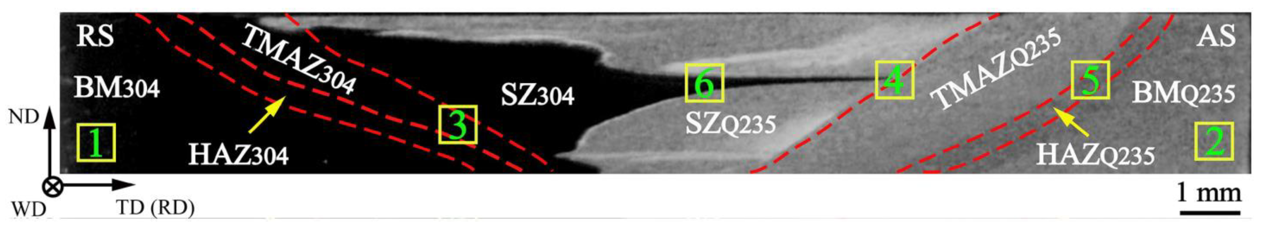
Wang et al. [
78] conducted a dissimilar FSW of Q235 low-carbon steel to 304 austenitic stainless steel at butt joints of 3 mm thickness each.
Table 9 illustrates the present elements and their weight% in welded 304 steel and Q235 plates. The FSW was performed by a WC-Co tool consisting of a pin shape with six truncated pyramids and a cylindrical shoulder. The rotational speed during FSW was 475 rpm, with a welding speed of 47.5 mm/min. The 304 steel and Q235 plates were positioned on the retreating side (RS) and AS, respectively.
The BM of the 304SS contained austenite with a 10.9 µm average grain size, whereas the BM of the Q235 steel contained ferrite and pearlite. The pearlite lamellar structure was located at the boundaries of ferrite grains. The ferrite had a 5.7 μm average grain size.
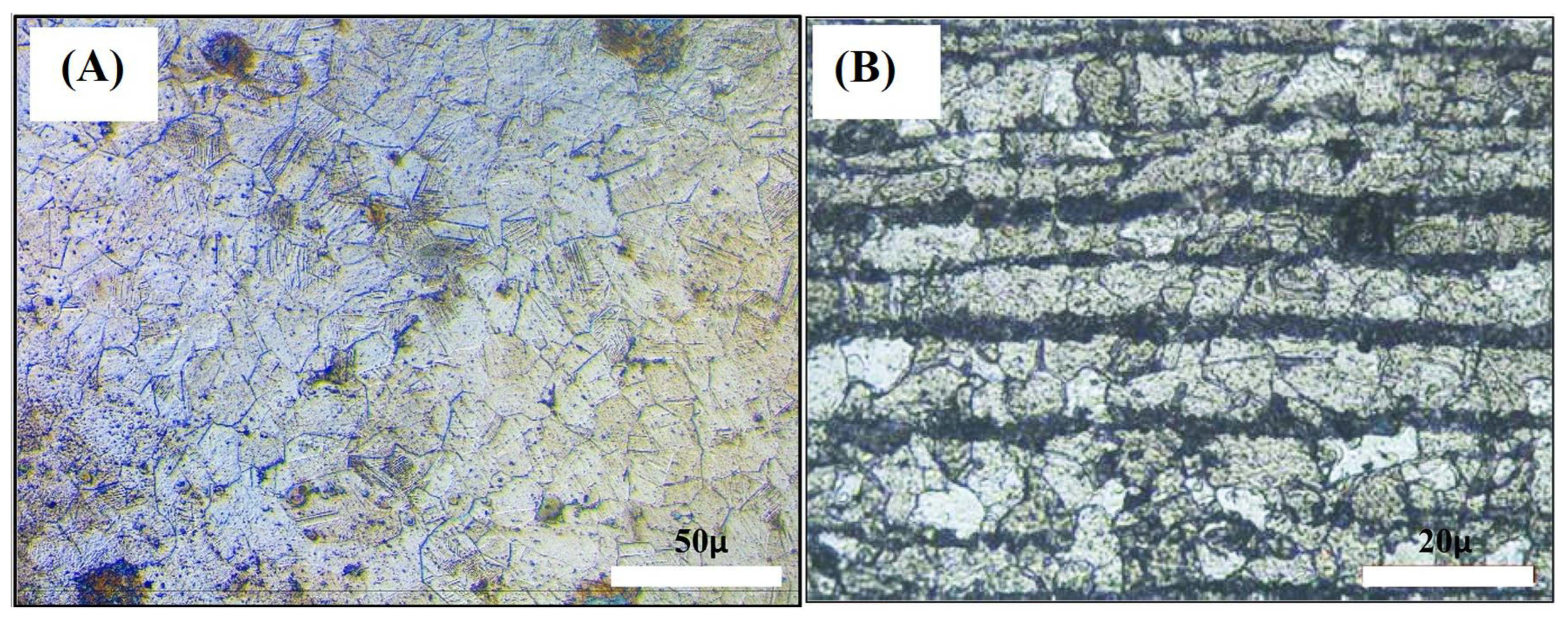
Figure 14 shows the dissimilar FSW joint macrostructure of Q235 and SS304 steels. After FSW, the SZ of the 304SS side showed a refined austenitic structure with a 5.5 μm average grain size due to the discontinuous dynamic recrystallization effect.
The results demonstrated that the SZ of the Q235 steel showed a combination of proeutectoid ferrite and pearlite phases; the ferrite had a 7.3 μm average grain size. The coarsening of the ferrite phase was attributed to the FSW-process-induced temperature. The welding temperature ranged between 947 and 1074 °C, which was greater than the Ac3 (austenitizing temperature) of the Q235 steel. The grain coarsening was attributed to pearlite coarsening induced by the temperature increase. The TMAZ showed grain refinement on the 304 side, while the grain size of the ferrite phase in the TMAZ was 8 μm on the Q234 side. The acicular ferrite amount was decreased. The HAZ was only subjected to a thermal cycle, so the HAZ showed grain coarsening on the 304 SS side while the fraction of LAGBs increased due to the occurrence of dynamic recovery. The ferrite grain size was 6 μm in the HAZ in the Q234 side.
On the other hand, the average BM microhardness values were 210 and 154 HV in the 304 SS and Q235 steel, respectively. The hardness of the welded joints (SZ, TMAZ, and HAZ) was increased on the two sides. However, the maximum microhardness, 325 HV, appeared on the SZ upper surface of the Q235 side due to the migration of Cr atoms from the 304 SS side to the Q235 steel side. Additionally, the FSW joint tensile strength was 493 MPa, which fell between the UTS of the two steels. The fracture was not located in the SS304 and Q235 low-carbon steel interface. It was instead located at the SZ of the Q235 steel, which indicates the higher strength of the interfacial bonding. However, the welded-joint elongation was lesser than the elongation of the two steels.
Matlan et al. [
99] performed FSW for stainless steel 316 and low C-steel by double-sided butt joints, the chemical composition of the joined steels is displayed in
Table 10. The sheets each had a 10 mm thickness. The FSW was carried out with a 100 mm/min traveling speed and 500 and 1000 rpm tool rotational speed in combination with preheating temperatures of 50 and 100 °C. The FSW tool was made of a composite material, W-Re-HfC, with a 20 mm shoulder, a truncated cone pin with a 5 mm tip pin diameter, and an 8 mm end pin diameter with a pin length of 5 mm.
The AISI 316 stainless steel was located on the weld AS, and the low C-steel was on the weld RS. The FSW was carried out in argon shielding gas to prevent surface oxidation of the weld metal. The BM of the 316 SS has an austenitic microstructure, while the BM microstructure of the C-steel has a mixed microstructure of equiaxed ferrite grains and pearlite colonies, as displayed in
Figure 15.
Their results demonstrated grain refinement in the two steels after FSW. No HAZ was observed in stainless steel. The joint interface demonstrated a complex swirl-like shape linked to the stirring flow path, while the flow lines, such as the onion ring structures, were not observed in the SZ. It was revealed that a thin layer of carbon steel material was stirred to the TMAZ of the stainless steel side. The use of a rotational speed of 1000 rpm and pre-heating at 50 °C displayed the greatest brittle behavior because of the micro-void formation in the brittle and hard phases in the weld zone. The length of the voids varied from 20 µm to 100 µm with a thickness of approximately 1–2 µm. During the U-Bend test, a crack a few millimeters in length was revealed in the TMAZ of the stainless steel section. Further, the specimens pre-heated at 50 °C and then welded at 1000 rpm exposed the presence of voids near the TMAZ of the stainless steel section.
Tiwari et al. [
100] also carried out FSW for welding butt joints of stainless steel, UNS S30400, and mild steel, UNS G10080. The sheets had a 4 mm thickness. The FSW was achieved using a tungsten carbide tool with rotational speeds of 600 and 875 rpm and tool offsets of 0.6 and 1.2 mm. The tool offset/eccentricity was executed by moving the tool towards the mild steel side; see
Figure 16. Tool wear occurred under different mechanisms (adhesion, abrasion, and oxidation wear). Tungsten particles were found in the SZ, which was detrimental to the weld joint impact strength. The BMs were mild steel (UNS S10080) and stainless steel (UNS 30400).
The results showed that the microstructure of SS304 and mild steel mainly consisted of the ferrite phase. However, the SS304 displayed higher tensile strength, percentage elongation, hardness, and fracture toughness compared to the mild steel. The SZ demonstrated the existence of ferrite, austenite, and carbide precipitates, as revealed by XRD. Moreover, the SZ showed large Ni and Cr peaks in the SS304-rich regions; thus, the MS region decreased, as revealed by EDS. Additionally, it was found that the joints’ YS and UTS increased with an increase in the tool offset distance and rotational speed. The increases in the UTS of the welded joints in SS304 and mild steel are attributed to the grain size and strengthening of phase transformation, respectively. However, the elongation to failure was 9.6%, which was a decline of 53.8% compared to the mild steel. In addition, it was found that the welded joints had lower ductility and fracture toughness than the base metals. Significant tool wear was observed, which negatively affected the mechanical properties.
On the other hand, the microhardness of mild steel BM and stainless-steel BM was about 88 HV0.5 and 149 HV0.5, respectively. The maximum hardness of the mild steel side ranged from 121 to 129 HV in SZ, from 95 to 102 HV in the HAZ, and from 106 to 116 HV in the TMAZ, which was attributed to microstructure refinement. The SZ with Widmanstatten ferrite and acicular ferrite structures had a maximum hardness of 281 HV0.5. The hardness values in the SZ and TMAZ of the welds were extremely ununiform because of the mixed complex material in the weld zone.
Ipekoğlu et al. [
101] conducted FSW of dissimilar low-carbon steel sheets with different carbon fractions of 0.17 and 0.25 wt.%, St37 and St52, respectively. The FSW was processed using a tungsten carbide tool. During the FSW process, the tool traverse speed and rotational rate were constant at 65 mm/min and 630 rpm, respectively. The BMs showed a mixed structure of pearlite and ferrite with different grain sizes of ferrite; the volume fractions of the pearlite phase were 9% and 18% in the St37 and St52, respectively. After FSW, the SZ showed a mixed structure of Widmanstatten ferrite, either ferrite with or without carbide aggregates. The low cooling rate in the SZ resulted in the appearance of the Widmanstatten ferrite phase. Moreover, the severe plastic deformation in the SZ led to perlite phase dissolution. The HAZ was composed of fine pearlite grains, fine equiaxed ferrite grains, and course ferrite grains.
Additionally, the BM showed hardness values equal to 180 HV in St52 and 137 in St37, respectively. However, the hardness of the SZ reached 347 HV due to grain refinement and solid-state transformation. The welded plates showed a UTS of 389 MPa, thus lying between the UTS of St37 (373 MPa) and St52 (526 MPa). Furthermore, the dissimilar joints recorded a yield strength of 272 MPa, which was also an intermediate value and fell between those of the joined base plates. The welded joint elongation reached 9%, which was lower than the ductility of St37 and St52 (45 and 35, respectively). The low ductility was attributed to the existence of Widmanstatten ferrite and/or cementite aggregates in the SZ.

 ,
, 


