
Numerical Modeling of Distortion of Ti-6Al-4V Components Manufactured Using Laser Powder Bed Fusion
 ,
,
Abstract
:1. Introduction
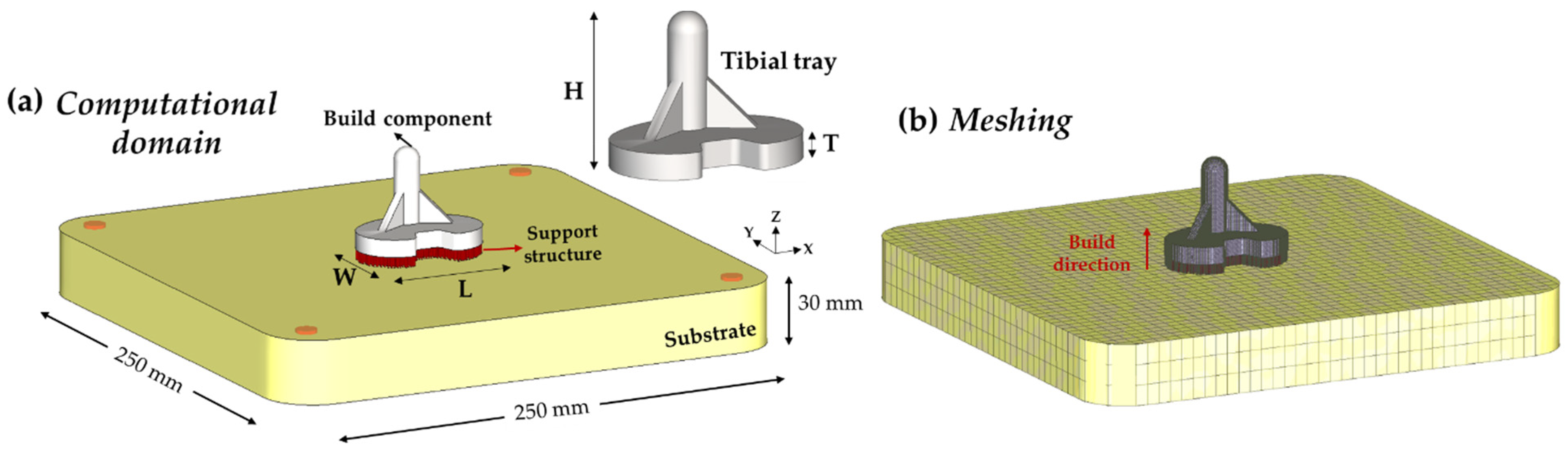
2. Numerical Modeling
2.1. Mechanical Modeling
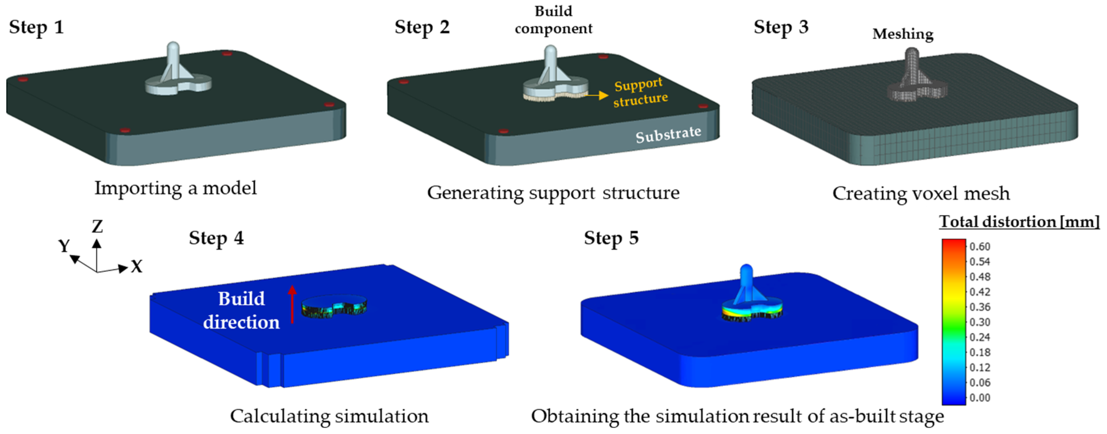
2.2. Numerical Modeling for Distortion Analysis
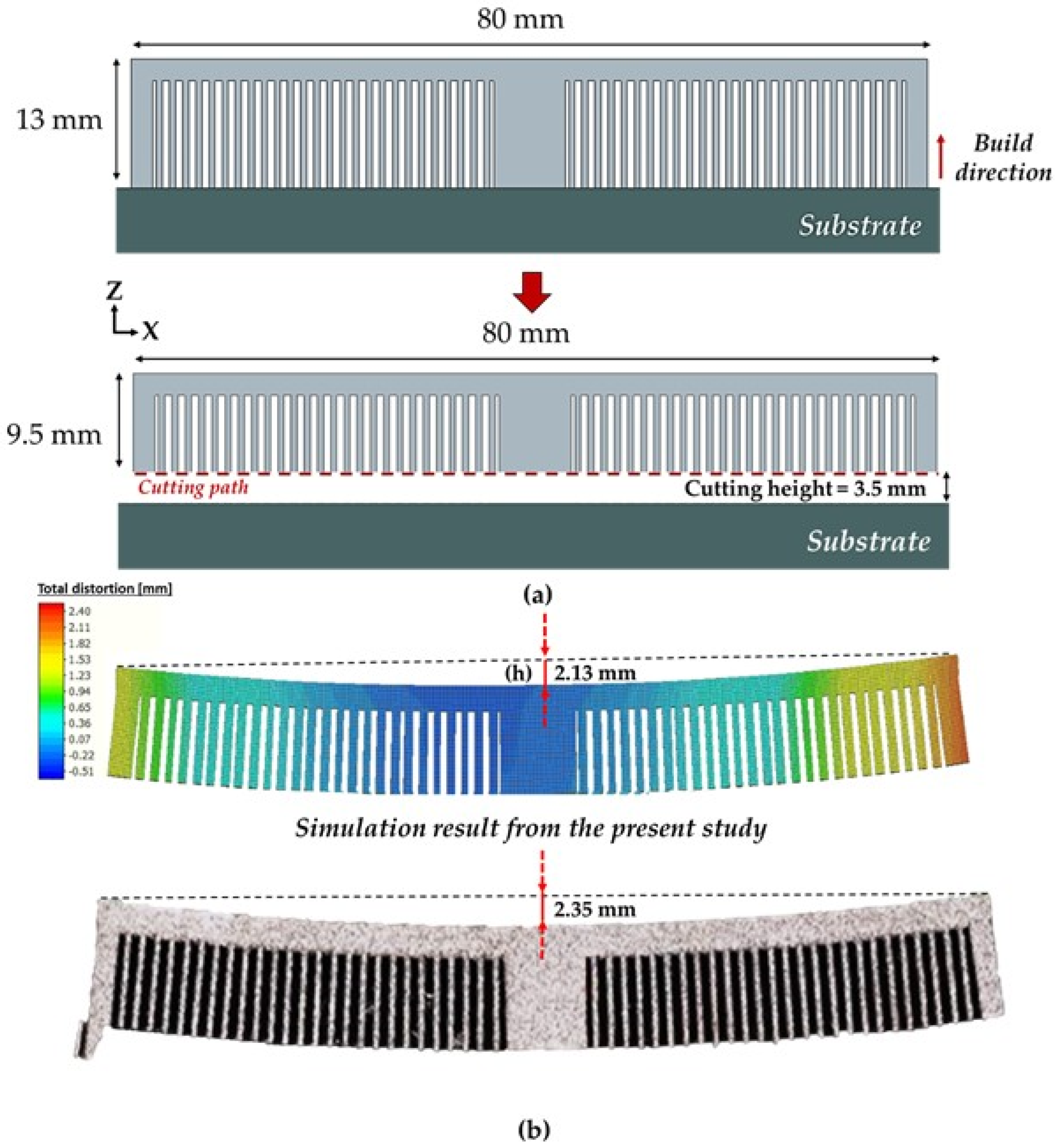
3. Model Validation
4. Results and Discussion
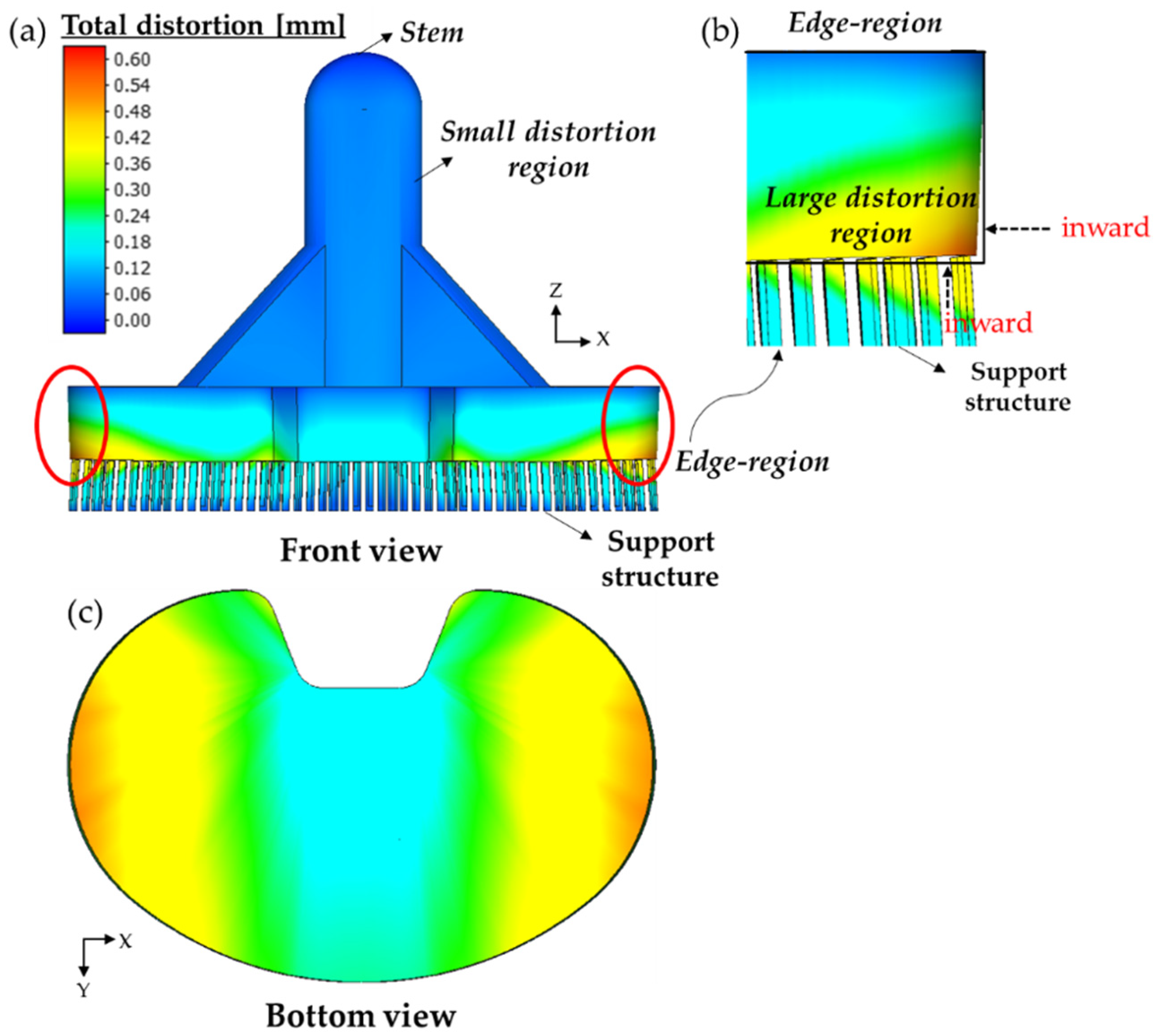
4.1. Distortion Distributions of Tibial Component
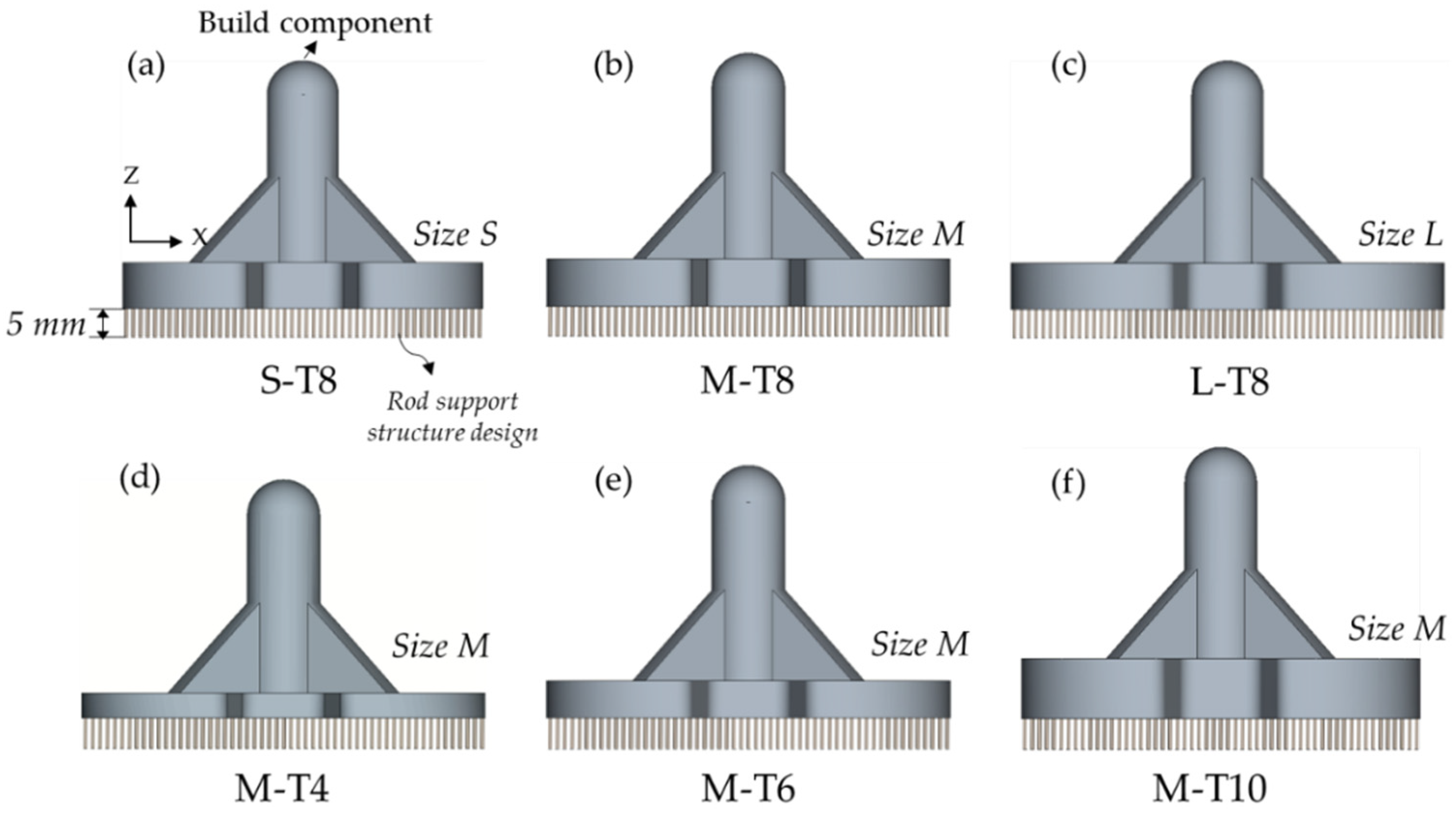
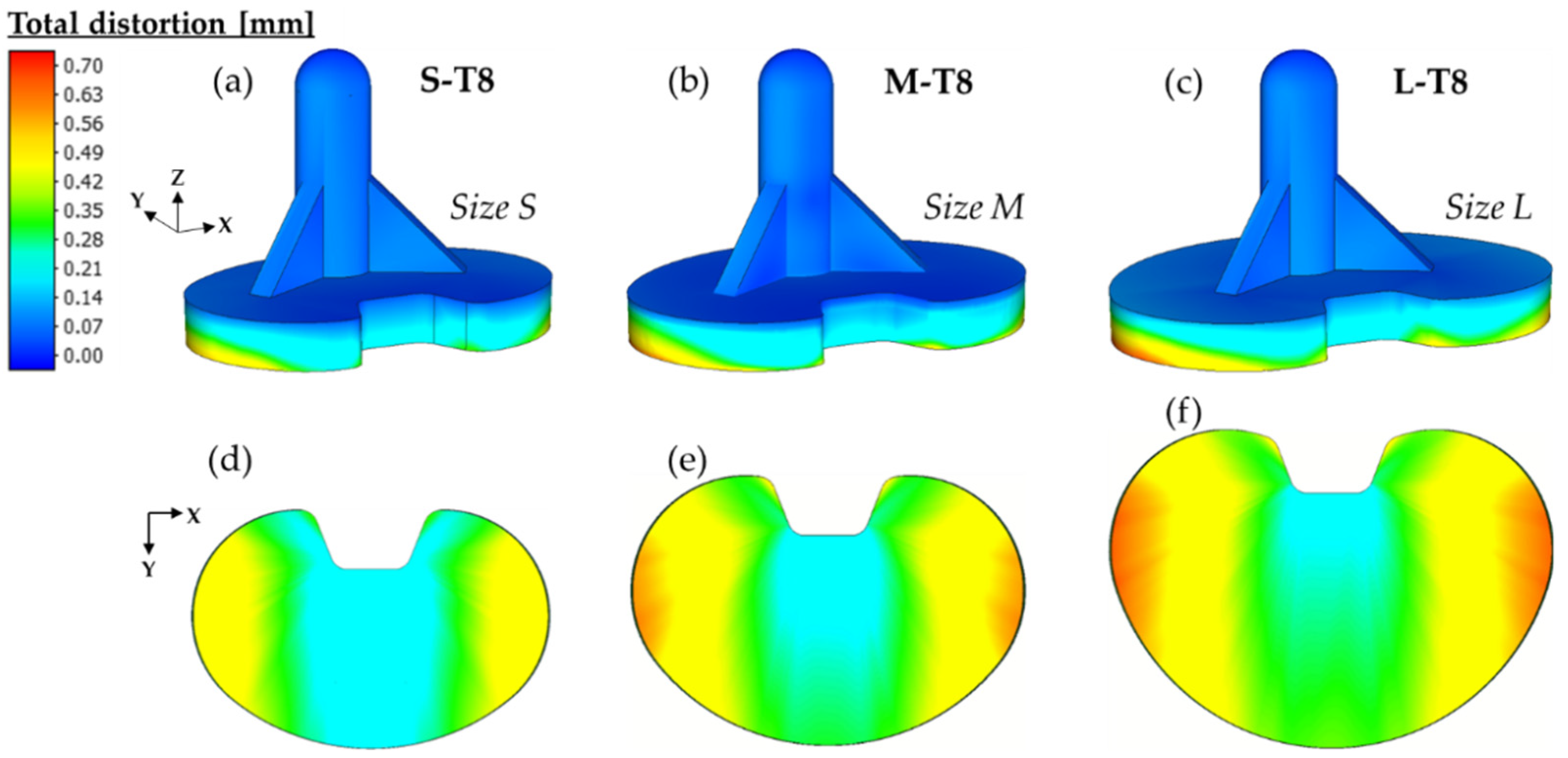
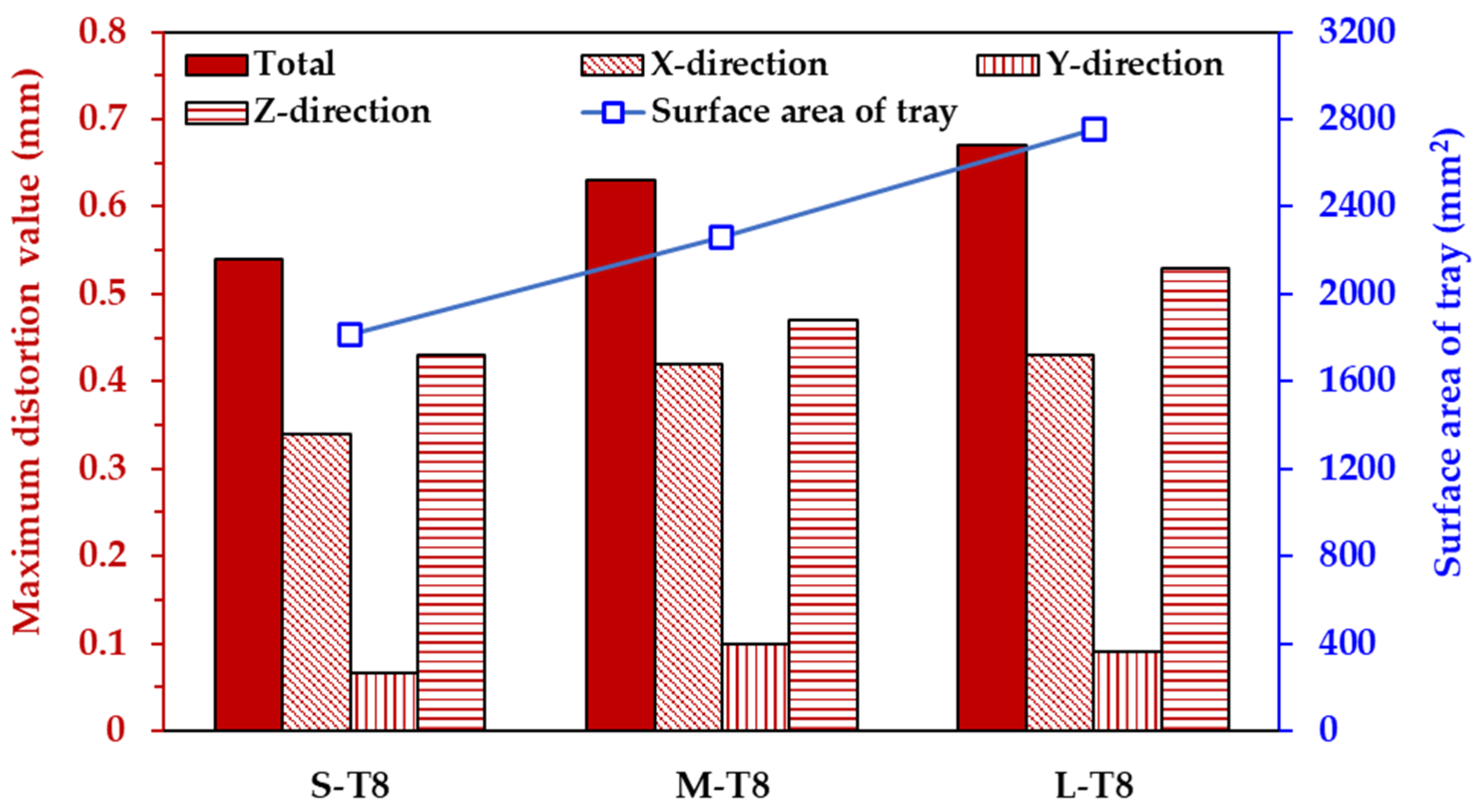
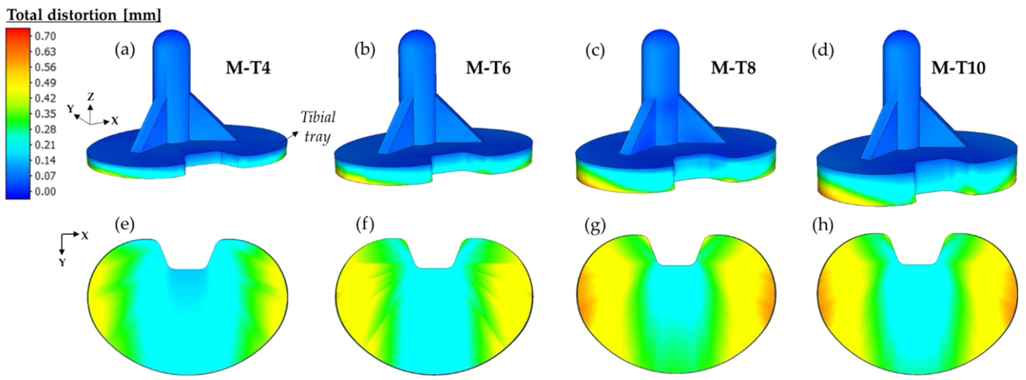
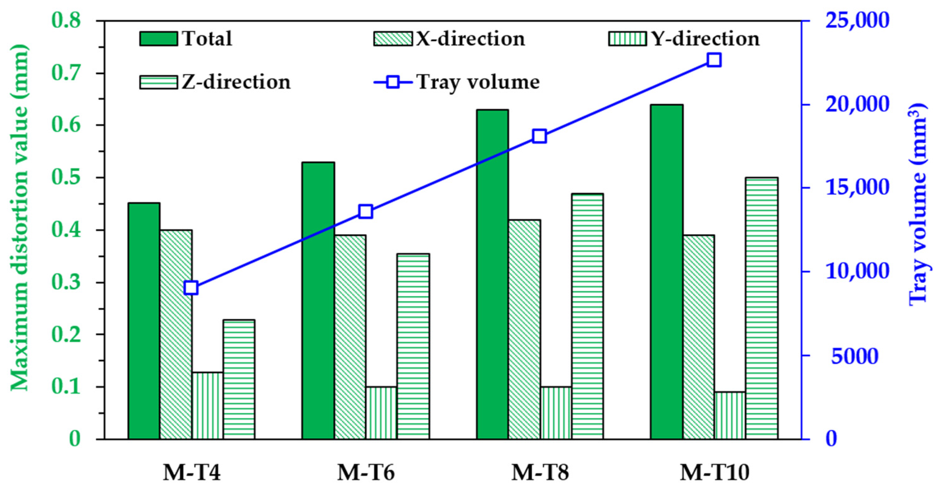
4.2. Effect of Part Sizes on the Distortion of Tibial Component
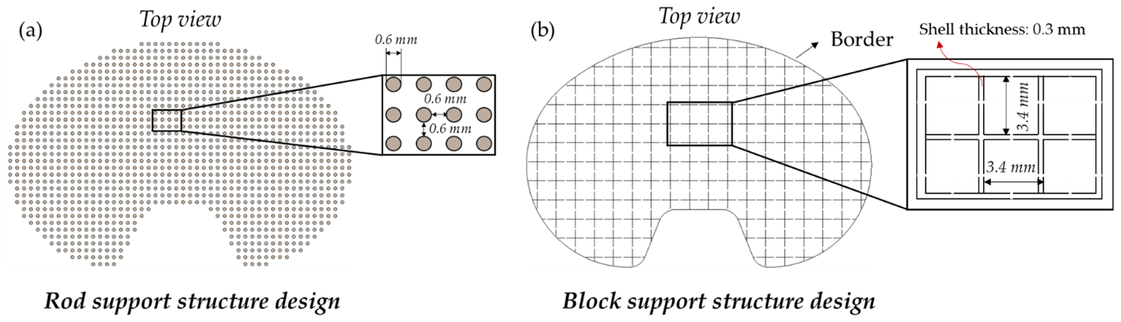
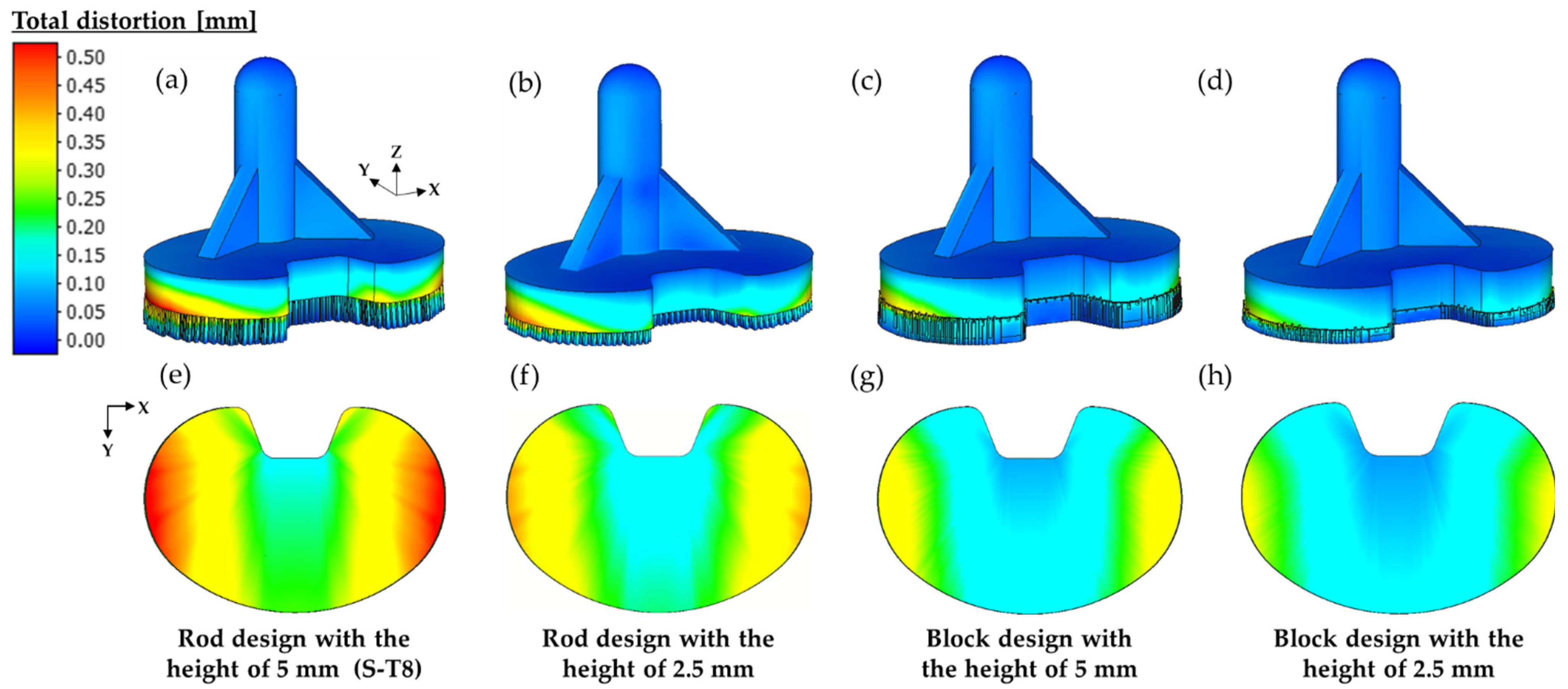
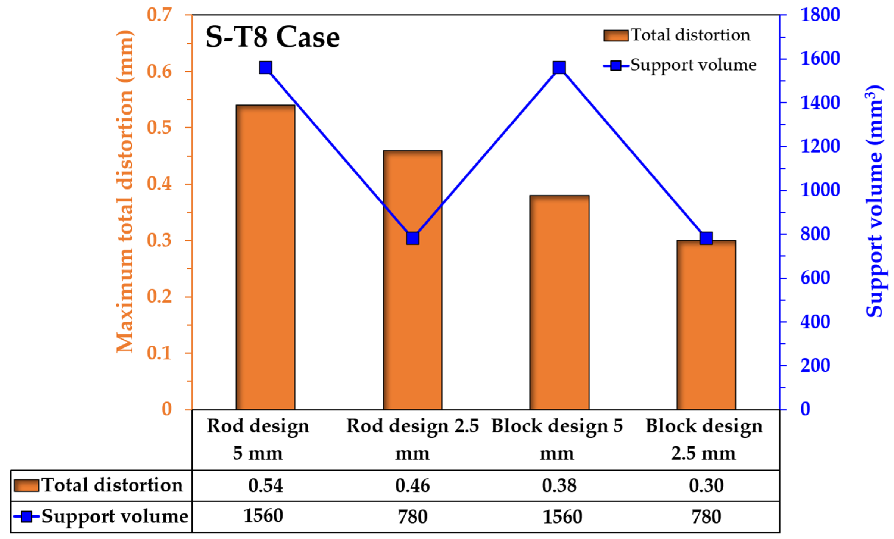
4.3. Effect of Support-Structure Design on the Distortion of Tibial Component
5. Conclusions
- The large distortion takes place near the interface between the tibial tray and support structure because of the different stiffness between solid bulk and support structure. The maximum distortion occurs around both edges of the long side of the tibial tray. In addition, the distortion value in the Z-direction was greater than that of the X- and Y-directions.
- The distortion of the tibial component increases with the larger size according to the surface area of the tibial tray. The thickness of the tibial tray tends to increase the distortion of the component, but has less effect on the higher thickness component.
- The support-structure design plays a significant role in distortion reduction. Decreasing the height of the support gives lower distortion and less material usage, while the difficulty of the part removal should be considered. Applying an appropriate design of the support, such as block structure instead of rod structure, gives a more effective reduction of the distortion than decreasing the support height.
Author Contributions
Funding
Institutional Review Board Statement
Informed Consent Statement
Data Availability Statement
Conflicts of Interest
References
- Shipley, H.; McDonnell, D.; Culleton, M.; Coull, R.; Lupoi, R.; O’Donnell, G.; Trimble, D. Optimisation of Process Parameters to Address Fundamental Challenges during Selective Laser Melting of Ti-6Al-4V: A Review. Int. J. Mach. Tools Manuf. 2018, 128, 1–20. [Google Scholar] [CrossRef]
- Agius, D.; Kourousis, K.; Wallbrink, C. A Review of the As-Built SLM Ti-6Al-4V Mechanical Properties towards Achieving Fatigue Resistant Designs. Metals 2018, 8, 75. [Google Scholar] [CrossRef]
- Bai, L.; Gong, C.; Chen, X.; Sun, Y.; Zhang, J.; Cai, L.; Zhu, S.; Xie, S.Q. Additive Manufacturing of Customized Metallic Orthopedic Implants: Materials, Structures, and Surface Modifications. Metals 2019, 9, 1004. [Google Scholar] [CrossRef]
- Ninpetch, P.; Kowitwarangkul, P.; Mahathanabodee, S.; Chalermkarnnon, P.; Rattanadecho, P. Computational Investigation of Thermal Behavior and Molten Metal Flow with Moving Laser Heat Source for Selective Laser Melting Process. Case Stud. Therm. Eng. 2021, 24, 100860. [Google Scholar] [CrossRef]
- Bayat, M.; Mohanty, S.; Hattel, J.H. Multiphysics Modelling of Lack-of-Fusion Voids Formation and Evolution in IN718 Made by Multi-Track/Multi-Layer L-PBF. Int. J. Heat Mass Transf. 2019, 139, 95–114. [Google Scholar] [CrossRef]
- Ninpetch, P.; Kowitwarangkul, P. A Numerical Study on the Thermal Transient Model with Moving Laser Heat Source of AISI 304 Stainless Steel Plate. Mater. Today Proc. 2019, 17, 1761–1767. [Google Scholar] [CrossRef]
- Ninpetch, P.; Teenok, N.; Kowitwarangkul, P.; Mahathanabodee, S.; Tongsri, R.; Ratanadecho, P. The Influence of Laser Parameters on the Melted Track and Microstructure of AISI 316L Fabricated by L-PBF Process. In Proceedings of the 8th Asia Pacific IIW International Congress 2019, Bangkok, Thailand, 20–22 March 2019; pp. 39–43. [Google Scholar]
- Ninpetch, P.; Chalermkarnnon, P.; Kowitwarangkul, P. Multiphysics Simulation of Thermal-Fluid Behavior in Laser Powder Bed Fusion of H13 Steel: Influence of Layer Thickness and Energy Input. Met. Mater. Int. 2022, 1–16. [Google Scholar] [CrossRef]
- Ninpetch, P.; Kowitwarangkul, P.; Mahathanabodee, S.; Chalermkarnnon, P.; Ratanadecho, P. A Review of Computer Simulations of Metal 3D Printing. AIP Conf. Proc. 2020, 2279, 050002. [Google Scholar] [CrossRef]
- Lu, X.; Chiumenti, M.; Cervera, M.; Tan, H.; Lin, X.; Wang, S. Warpage Analysis and Control of Thin-Walled Structures Manufactured by Laser Powder Bed Fusion. Metals 2021, 11, 686. [Google Scholar] [CrossRef]
- Botha, H.; Marais, D.; Kloppers, C.P. The Efficacy of The Inherent Strain Method in Determining Residual Stress in In718 SLM Specimens. S. Afr. J. Ind. Eng. 2021, 32, 264–278. [Google Scholar] [CrossRef]
- Mugwagwa, L.; Dimitrov, D.; Matope, S.; Muvunzi, R. Residual Stresses and Distortions in Selective Laser Meltinga Review. In Proceedings of the 17th Rapid Product Development Association of South Africa, Vanderbijlpark, South Africa, 2–4 November 2016. [Google Scholar]
- Ninpetch, P.; Kowitwarangkul, P.; Mahathanabodee, S.; Tongsri, R.; Ratanadecho, P. Thermal and Melting Track Simulations of Laser Powder Bed Fusion (L-PBF). IOP Conf. Ser. Mater. Sci. Eng. 2019, 526, 012030. [Google Scholar] [CrossRef]
- DebRoy, T.; Wei, H.L.; Zuback, J.S.; Mukherjee, T.; Elmer, J.W.; Milewski, J.O.; Beese, A.M.; Wilson-Heid, A.; De, A.; Zhang, W. Additive Manufacturing of Metallic ComponentsProcess, Structure and Properties. Prog. Mater. Sci. 2018, 92, 112–224. [Google Scholar] [CrossRef]
- De Baere, D.; Van Cauwenbergh, P.; Bayat, M.; Mohanty, S.; Thorborg, J.; Thijs, L.; Van Hooreweder, B.; Vanmeensel, K.; Hattel, J.H. Thermo-Mechanical Modelling of Stress Relief Heat Treatments after Laser-Based Powder Bed Fusion. Addit. Manuf. 2021, 38, 101818. [Google Scholar] [CrossRef]
- Li, K.; Ma, R.; Zhang, M.; Chen, W.; Li, X.; Zhang, D.Z.; Tang, Q.; Murr, L.E.; Li, J.; Cao, H. Hybrid Post-Processing Effects of Magnetic Abrasive Finishing and Heat Treatment on Surface Integrity and Mechanical Properties of Additively Manufactured Inconel 718 Superalloys. J. Mater. Sci. Technol. 2022, 128, 10–21. [Google Scholar] [CrossRef]
- Yakout, M.; Elbestawi, M.A.; Veldhuis, S.C.; Nangle-Smith, S. Influence of Thermal Properties on Residual Stresses in SLM of Aerospace Alloys. Rapid Prototyp. J. 2020, 26, 213–222. [Google Scholar] [CrossRef]
- Ahmed, A.; Majeed, A.; Atta, Z.; Jia, G. Dimensional Quality and Distortion Analysis of Thin-Walled Alloy Parts of AlSi10Mg Manufactured by Selective Laser Melting. J. Manuf. Mater. Process 2019, 3, 51. [Google Scholar] [CrossRef]
- Bian, P.; Shi, J.; Liu, Y.; Xie, Y. Influence of Laser Power and Scanning Strategy on Residual Stress Distribution in Additively Manufactured 316L Steel. Opt. Laser Technol. 2020, 132, 106477. [Google Scholar] [CrossRef]
- Han, Q.; Gu, H.; Soe, S.; Setchi, R.; Lacan, F.; Hill, J. Manufacturability of AlSi10Mg Overhang Structures Fabricated by Laser Powder Bed Fusion. Mater. Des. 2018, 160, 1080–1095. [Google Scholar] [CrossRef]
- Hajnys, J.; Pagáč, M.; Měsíček, J.; Petru, J.; Król, M. Influence of Scanning Strategy Parameters on Residual Stress in the SLM Process According to the Bridge Curvature Method for AISI 316L Stainless Steel. Materials 2020, 13, 1659. [Google Scholar] [CrossRef]
- Setien, I.; Chiumenti, M.; van der Veen, S.; San Sebastian, M.; Garciandía, F.; Echeverría, A. Empirical Methodology to Determine Inherent Strains in Additive Manufacturing. Comput. Math. Appl. 2019, 78, 2282–2295. [Google Scholar] [CrossRef] [Green Version]
- Bugatti, M.; Semeraro, Q. Limitations of the Inherent Strain Method in Simulating Powder Bed Fusion Processes. Addit. Manuf. 2018, 23, 329–346. [Google Scholar] [CrossRef]
- Soylemez, E.; Koç, E.; Coşkun, M. Thermo-mechanical simulations of selective laser melting for AlSi10Mg alloy to predict the part-scale deformations. Prog. Addit. Manuf. 2019, 4, 465–478. [Google Scholar] [CrossRef]
- Liang, X.; Cheng, L.; Chen, Q.; Yang, Q.; To, A.C. A Modified Method for Estimating Inherent Strains from Detailed Process Simulation for Fast Residual Distortion Prediction of Single-Walled Structures Fabricated by Directed Energy Deposition. Addit. Manuf. 2018, 23, 471–486. [Google Scholar] [CrossRef]
- Li, C.; Liu, J.F.; Fang, X.Y.; Guo, Y.B. Efficient Predictive Model of Part Distortion and Residual Stress in Selective Laser Melting. Addit. Manuf. 2017, 17, 157–168. [Google Scholar] [CrossRef]
- Promoppatum, P.; Yao, S.-C. Influence of Scanning Length and Energy Input on Residual Stress Reduction in Metal Additive Manufacturing: Numerical and Experimental Studies. J. Manuf. Process. 2020, 49, 247–259. [Google Scholar] [CrossRef]
- Taufek, T.; Manurung, Y.H.; Lüder, S.; Graf, M.; Salleh, F.M. Distortion Analysis of SLM Product of SS316L Using Inherent Strain Method. IOP Conf. Ser. Mater. Sci. Eng. 2020, 834, 012011. [Google Scholar] [CrossRef]
- Xiaohui, J.; Chunbo, Y.; Honglan, G.; Shan, G.; Yong, Z. Effect of Supporting Structure Design on Residual Stresses in Selective Laser Melting of AlSi10Mg. Int. J. Adv. Manuf. Technol. 2022, 118, 1597–1608. [Google Scholar] [CrossRef]
- Bompos, D.; Chaves-Jacob, J.; Sprauel, J.-M. Shape Distortion Prediction in Complex 3D Parts Induced during the Selective Laser Melting Process. CIRP Ann. Manuf. Technol. 2020, 69, 517–520. [Google Scholar] [CrossRef]
- Zhang, X.; Kang, J.; Rong, Y.; Wu, P.; Feng, T. Effect of Scanning Routes on the Stress and Deformation of Overhang Structures Fabricated by SLM. Materials 2018, 12, 47. [Google Scholar] [CrossRef]
- Chen, Q.; Liang, X.; Hayduke, D.; Liu, J.; Cheng, L.; Oskin, J.; Whitmore, R.; To, A.C. An Inherent Strain Based Multiscale Modeling Framework for Simulating Part-Scale Residual Deformation for Direct Metal Laser Sintering. Addit. Manuf. 2019, 28, 406–418. [Google Scholar] [CrossRef]
- Liang, X.; Hayduke, D.; To, A.C. An Enhanced Layer Lumping Method for Accelerating Simulation of Metal Components Produced by Laser Powder Bed Fusion. Addit. Manuf. 2021, 39, 101881. [Google Scholar] [CrossRef]
- Xing, W.; Ouyang, D.; Li, N.; Liu, L. Estimation of Residual Stress in Selective Laser Melting of a Zr-Based Amorphous Alloy. Materials 2018, 11, 1480. [Google Scholar] [CrossRef] [PubMed]
- Liang, X.; Chen, Q.; Cheng, L.; Hayduke, D.; To, A.C. Modified Inherent Strain Method for Efficient Prediction of Residual Deformation in Direct Metal Laser Sintered Components. Comput. Mech. 2019, 64, 1719–1733. [Google Scholar] [CrossRef]
- De Baere, D.; Moshiri, M.; Smolej, L.; Hattel, J.H. Numerical Investigation into Laser-Based Powder Bed Fusion of Cantilevers Produced in 300-Grade Maraging Steel. Addit. Manuf. 2022, 50, 102560. [Google Scholar] [CrossRef]
- Promoppatum, P.; Uthaisangsuk, V. Part Scale Estimation of Residual Stress Development in Laser Powder Bed Fusion Additive Manufacturing of Inconel 718. Finite Elem. Anal. Des. 2021, 189, 103528. [Google Scholar] [CrossRef]
- Yakout, M.; Elbestawi, M.A.; Veldhuis, S.C. A Study of the Relationship between Thermal Expansion and Residual Stresses in Selective Laser Melting of Ti-6Al-4V. J. Manuf. Process. 2020, 52, 181–192. [Google Scholar] [CrossRef]
- Chen, C.; Xiao, Z.; Zhu, H.; Zeng, X. Deformation and Control Method of Thin-Walled Part during Laser Powder Bed Fusion of Ti–6Al–4V Alloy. Int. J. Adv. Manuf. Technol. 2020, 110, 3467–3478. [Google Scholar] [CrossRef]
- Yang, T.; Xie, D.; Yue, W.; Wang, S.; Rong, P.; Shen, L.; Zhao, J.; Wang, C. Distortion of Thin-Walled Structure Fabricated by Selective Laser Melting Based on Assumption of Constraining Force-Induced Distortion. Metals 2019, 9, 1281. [Google Scholar] [CrossRef]
- Gouge, M.; Denlinger, E.; Irwin, J.; Li, C.; Michaleris, P. Experimental Validation of Thermo-Mechanical Part-Scale Modeling for Laser Powder Bed Fusion Processes. Addit. Manuf. 2019, 29, 100771. [Google Scholar] [CrossRef]
- Pagac, M.; Hajnys, J.; Halama, R.; Aldabash, T.; Mesicek, J.; Jancar, L.; Jansa, J. Prediction of Model Distortion by FEM in 3D Printing via the Selective Laser Melting of Stainless Steel AISI 316L. Appl. Sci. 2021, 11, 1656. [Google Scholar] [CrossRef]
- Gao, S.; Tan, Z.; Lan, L.; He, B. Effects of Geometrical Size and Structural Feature on the Shape-Distortion Behavior of Hollow Ti-Alloy Blade Fabricated by Additive Manufacturing Process. J. Laser Appl. 2020, 32, 032005. [Google Scholar] [CrossRef]
- Gao, S.; Tan, Z.; Lan, L.; Lu, G.; He, B. Experimental Investigation and Numerical Simulation of Residual Stress and Distortion of Ti6Al4V Components Manufactured Using Selective Laser Melting. J. Mater. Eng. Perform. 2022, 1–11. [Google Scholar] [CrossRef]
- Jia, H.; Sun, H.; Wang, H.; Wu, Y.; Wang, H. Size Effect in Selective Laser Melting Additive Manufacturing of 700 mm Large Component. J. Manuf. Process. 2022, 75, 125–137. [Google Scholar] [CrossRef]
- Sulaiman, M.R.; Yusof, F.; Jamaludin, M.F.B. Effect of Support Structure Design on the Part Built Using Selective Laser Melting. In Advances in Material Sciences and Engineering; Awang, M., Emamian, S.S., Yusof, F., Eds.; Springer: Singapore, 2020; pp. 275–286. ISBN 9789811382963. [Google Scholar]
- Siewert, M.; Neugebauer, F.; Epp, J.; Ploshikhin, V. Validation of Mechanical Layer Equivalent Method for Simulation of Residual Stresses in Additive Manufactured Components. Comput. Math. Appl. 2019, 78, 2407–2416. [Google Scholar] [CrossRef]
- Simufact Engineering Gmbh MSC Software Company. Simufact Additive Material Database 2020; Simufact Engineering Gmbh MSC Software Company: Tokyo, Japan, 2020. [Google Scholar]
- Li, Z.; Xu, R.; Zhang, Z.; Kucukkoc, I. The Influence of Scan Length on Fabricating Thin-Walled Components in Selective Laser Melting. Int. J. Mach. Tools Manuf. 2018, 126, 1–12. [Google Scholar] [CrossRef]
- Shi, X.; Liu, X.; Ren, S.; Lu, P.; Xie, Z.; Wu, M. Selective Laser Melting Fabricated Tungsten with Thin-Walled Structure: Role of Linear Energy Density on Temperature Evolution and Manufacturing Quality. Int. J. Mater. Form. 2022, 15, 2. [Google Scholar] [CrossRef]
- Cao, Q.; Bai, Y.; Zhang, J.; Shi, Z.; Fuh, J.Y.H.; Wang, H. Removability of 316L Stainless Steel Cone and Block Support Structures Fabricated by Selective Laser Melting (SLM). Mater. Des. 2020, 191, 108691. [Google Scholar] [CrossRef]


| No. | Part Geometry | Studies |
|---|---|---|
| 1 | Cantilever beam | [15,22,23,31,32,33,34,35,36] * |
| 2 | Cubic sample | [27,37,38] |
| 3 | Thin-walled part | [10,39,40] |
| 4 | Canonical sample | [24,32,41] |
| 5 | Complex shape parts | [42,43,44,45] |
| Case Studies | Size ** | Dimensions | Code Name | ||||
|---|---|---|---|---|---|---|---|
| Tray Thickness (T) (mm) | Length (L) (mm) | Width (W) (mm) | Height (H) (mm) | Tray Volume (mm3) | |||
| 1 | S | 8 | 60 | 40 | 43 | 14,516 | S-T8 |
| 2 | M | 8 | 66 | 45 | 43 | 18,097 | M-T8 |
| 3 | L | 8 | 72 | 50 | 43 | 22,034 | L-T8 |
| 4 | M | 4 | 66 | 45 | 39 | 9049 | M-T4 |
| 5 | M | 6 | 66 | 45 | 41 | 13,573 | M-T6 |
| 6 | M | 10 | 66 | 45 | 45 | 22,622 | M-T10 |
| Material Properties | Values |
|---|---|
| Density | 4.4 g/cm3 |
| Young’s modulus | 110 GPa |
| Yield strength | 1030 MPa |
| Poisson’s ratio | 0.31 |
| Process Parameters | Values |
|---|---|
| Laser power | 180 W |
| Scanning speed | 1250 mm/s |
| Layer thickness | 0.03 mm |
| Hatch spacing | 0.105 mm |
Publisher’s Note: MDPI stays neutral with regard to jurisdictional claims in published maps and institutional affiliations. |
© 2022 by the authors. Licensee MDPI, Basel, Switzerland. This article is an open access article distributed under the terms and conditions of the Creative Commons Attribution (CC BY) license (https://creativecommons.org/licenses/by/4.0/).
Share and Cite
Ninpetch, P.; Kowitwarangkul, P.; Chalermkarnnon, P.; Promoppatum, P.; Chuchuay, P.; Rattanadecho, P. Numerical Modeling of Distortion of Ti-6Al-4V Components Manufactured Using Laser Powder Bed Fusion. Metals 2022, 12, 1484. https://doi.org/10.3390/met12091484
Ninpetch P, Kowitwarangkul P, Chalermkarnnon P, Promoppatum P, Chuchuay P, Rattanadecho P. Numerical Modeling of Distortion of Ti-6Al-4V Components Manufactured Using Laser Powder Bed Fusion. Metals. 2022; 12(9):1484. https://doi.org/10.3390/met12091484
Chicago/Turabian StyleNinpetch, Patiparn, Pruet Kowitwarangkul, Prasert Chalermkarnnon, Patcharapit Promoppatum, Piyapat Chuchuay, and Phadungsak Rattanadecho. 2022. "Numerical Modeling of Distortion of Ti-6Al-4V Components Manufactured Using Laser Powder Bed Fusion" Metals 12, no. 9: 1484. https://doi.org/10.3390/met12091484