
Electron Beam-Melting and Laser Powder Bed Fusion of Ti6Al4V: Transferability of Process Parameters

Abstract
:1. Introduction
1.1. Laser Powder Bed Fusion (LPBF)
1.2. Electron Beam-Melting (EBM)
2. Materials and Methods
2.1. Machines
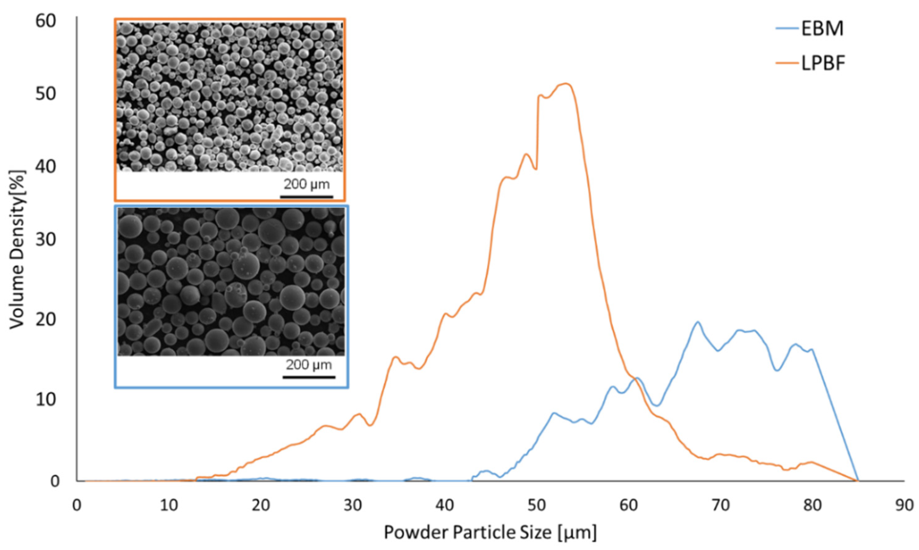
2.2. Ti6Al4V Powders
2.3. Experimental Samples
2.4. Roughness
2.5. Relative Density
2.6. Hardness
2.7. Melt-Pool Dimensions
3. Results and Discussion
3.1. Process Parameters
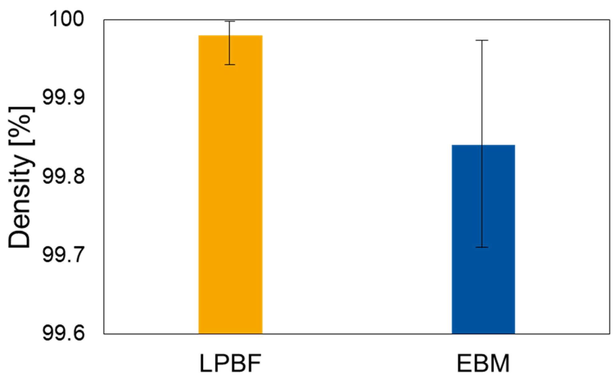
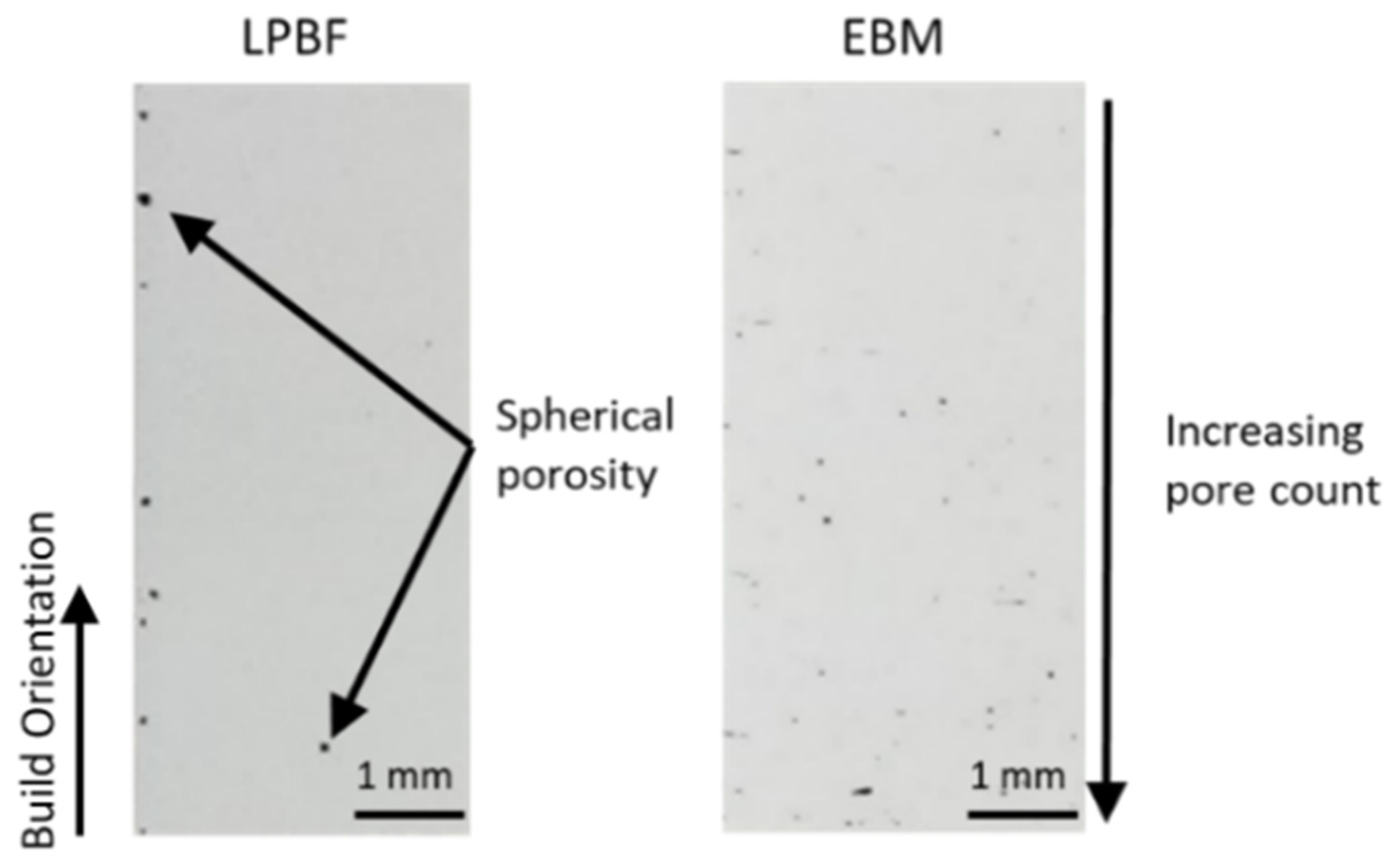
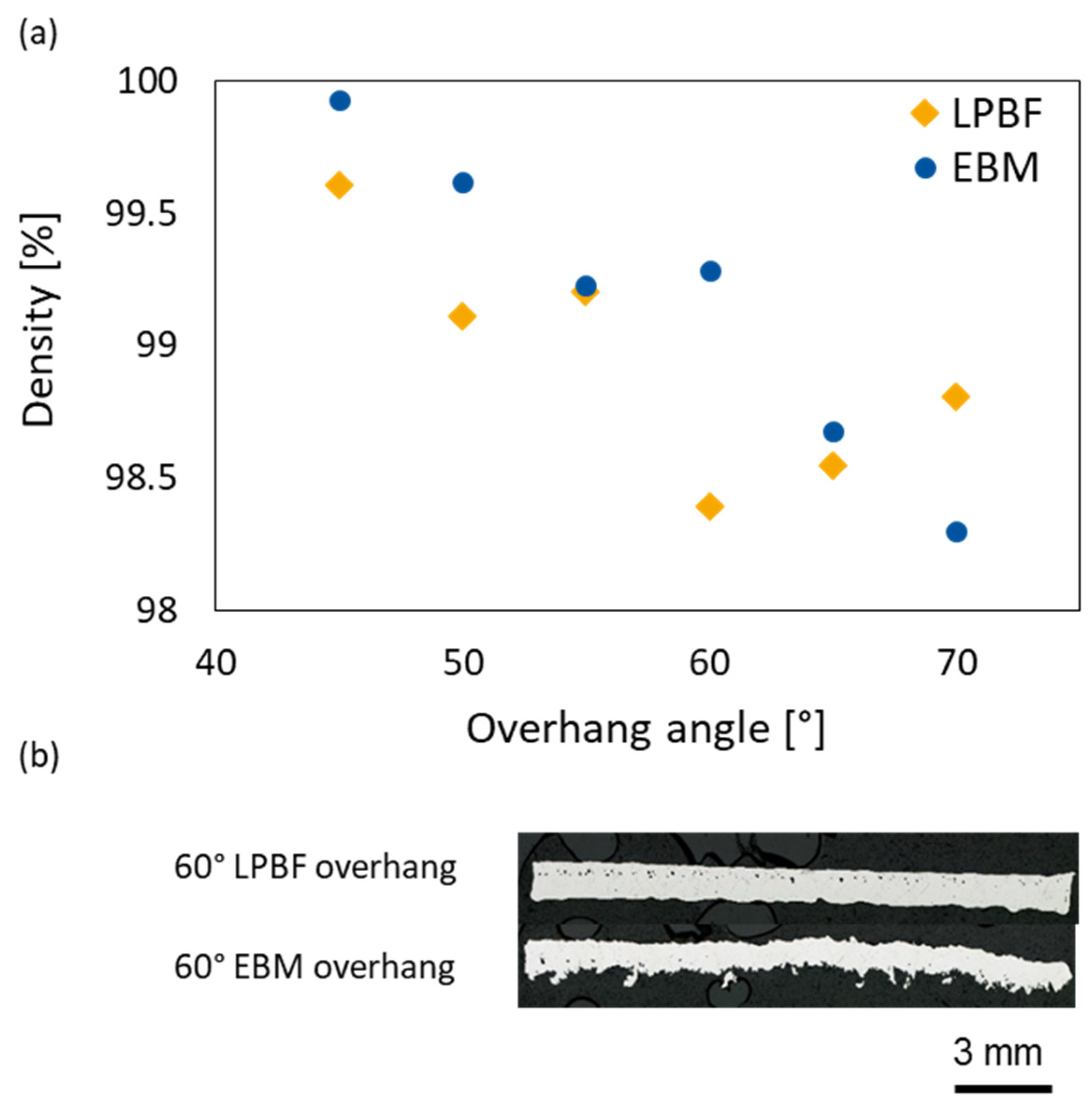
3.2. Relative Density
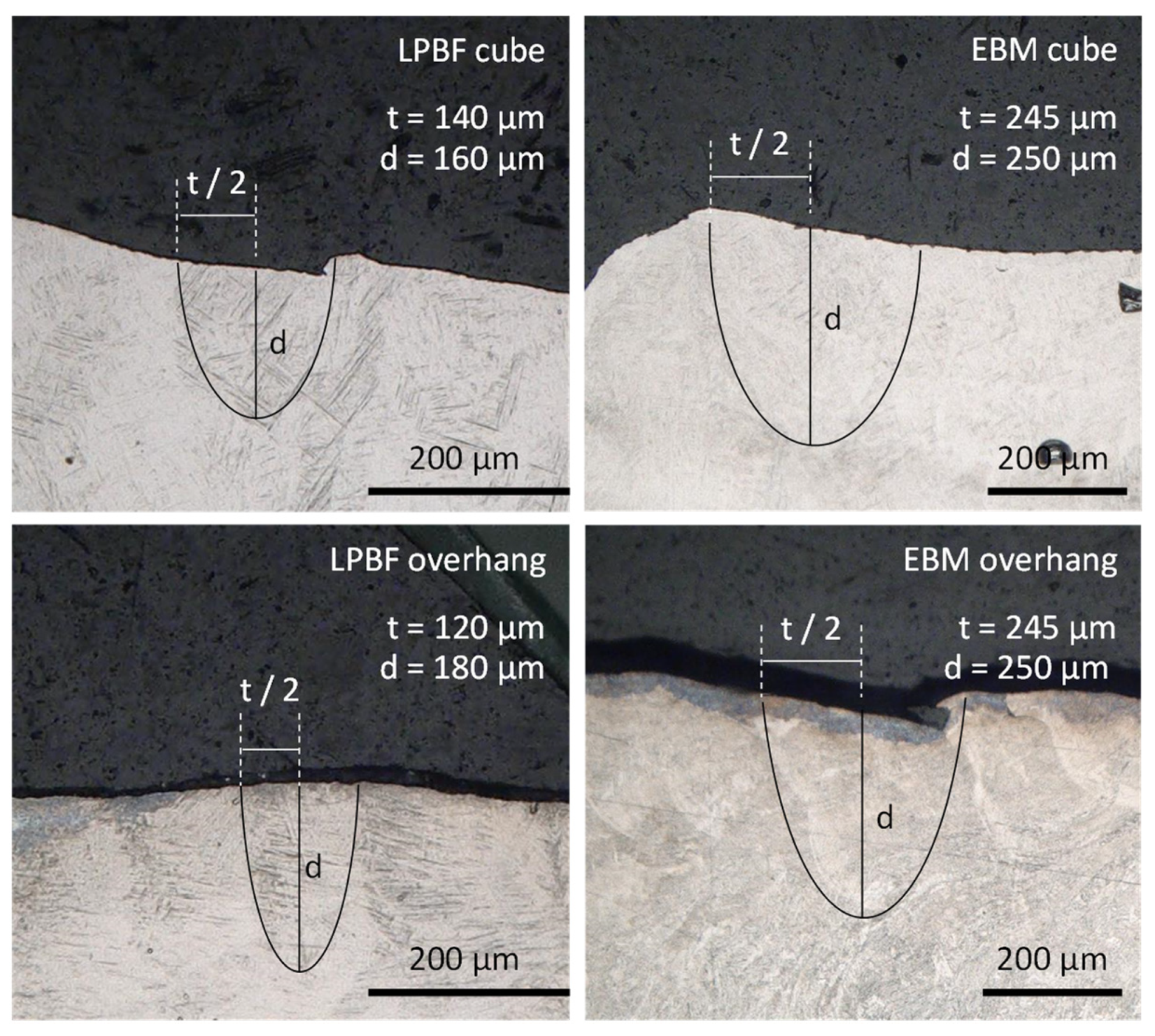
3.3. Melt-Pool Size
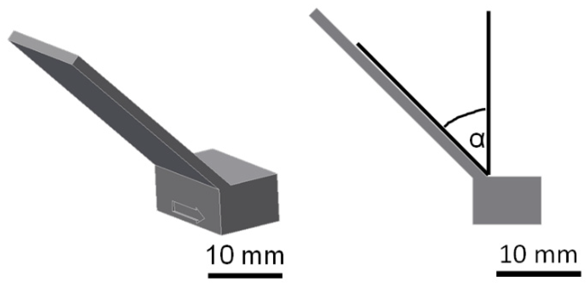
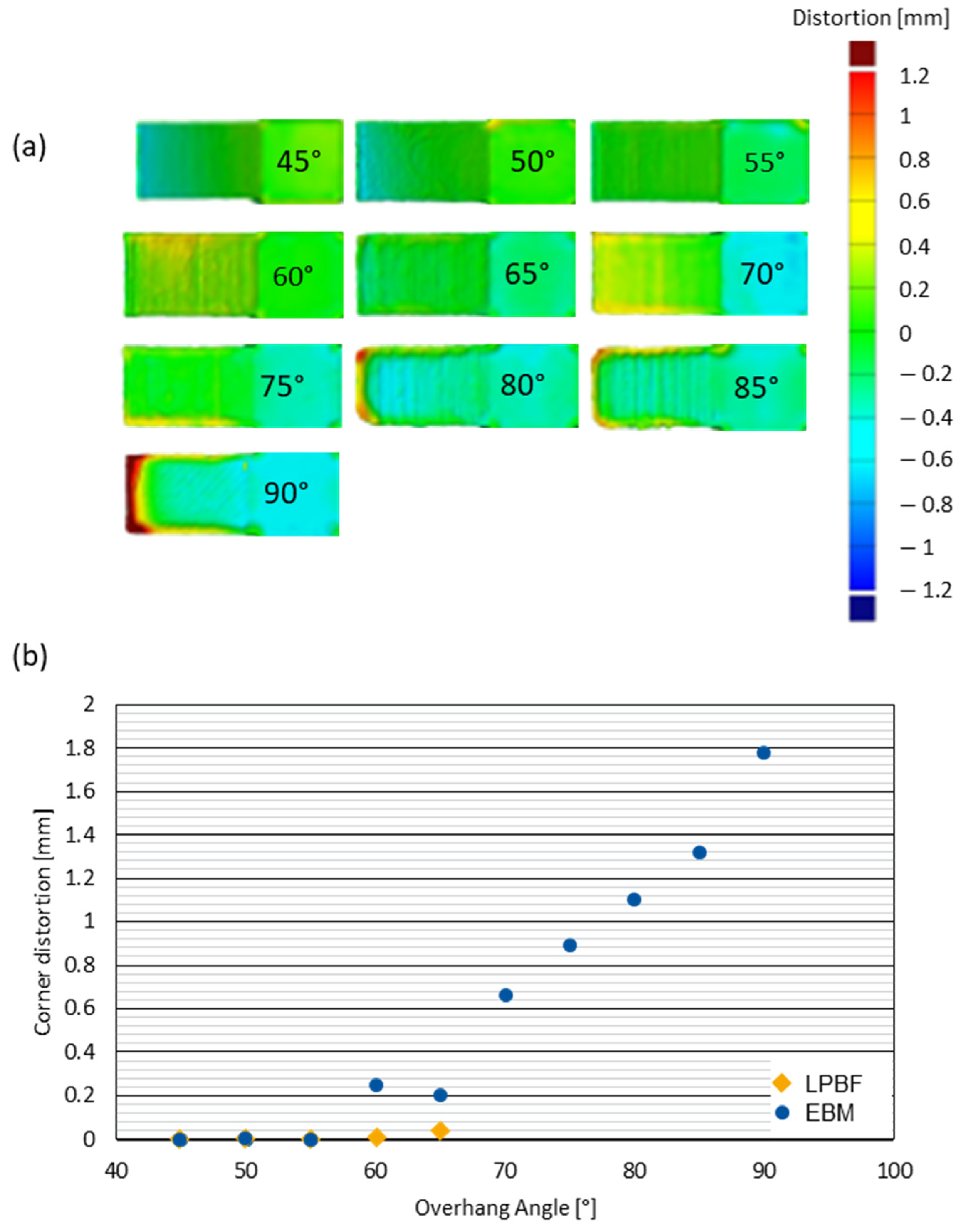
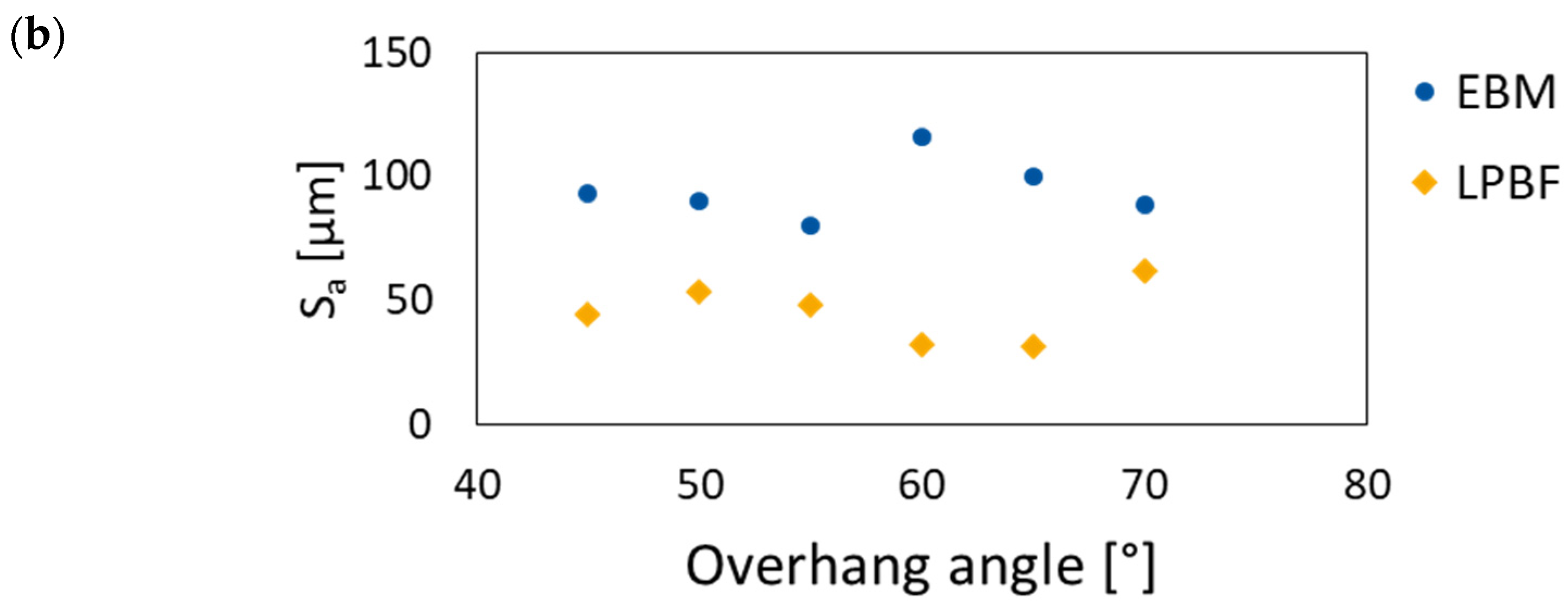
3.4. Geometrical Accuracy of Overhangs
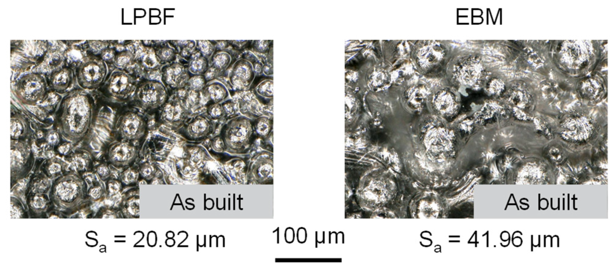
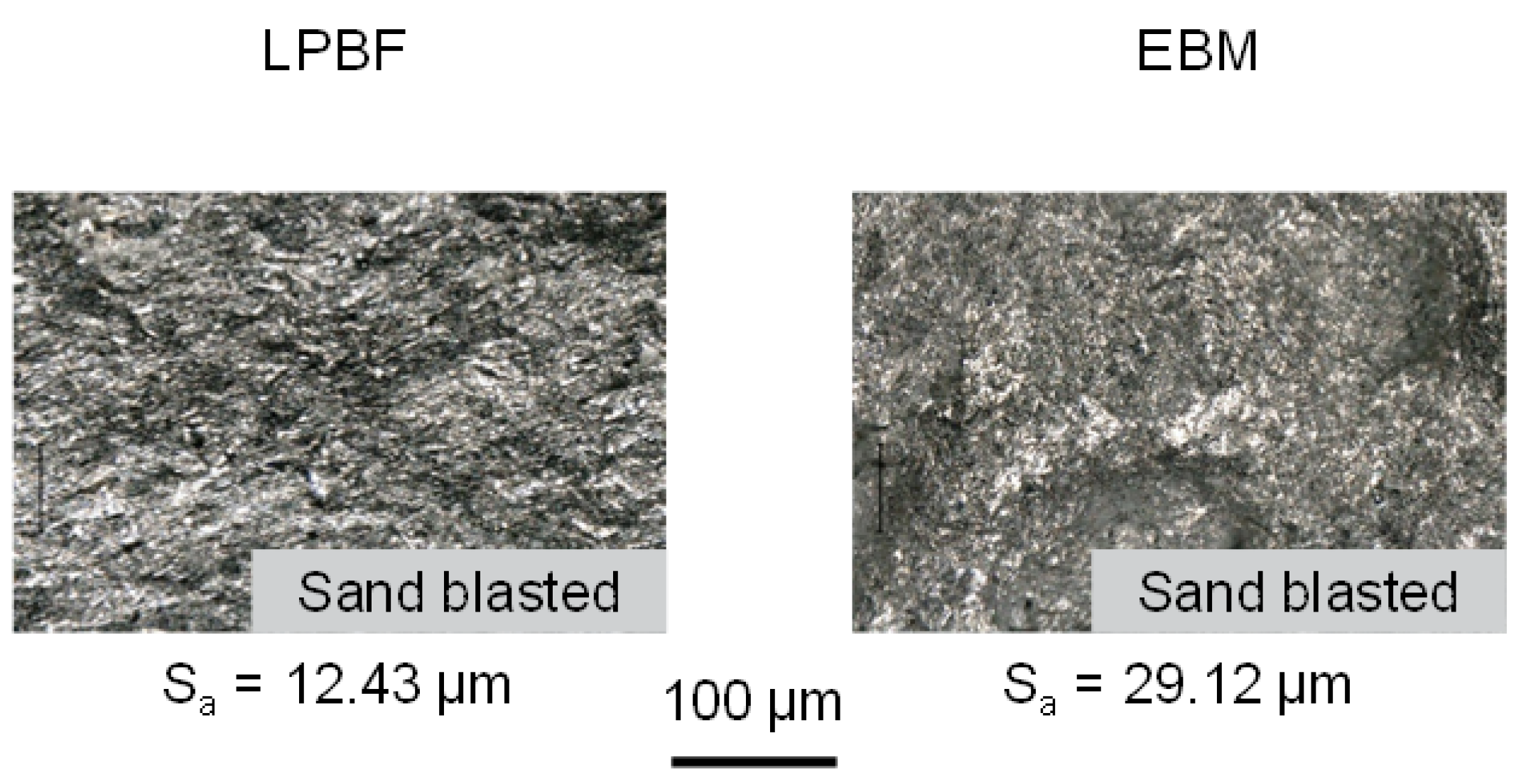
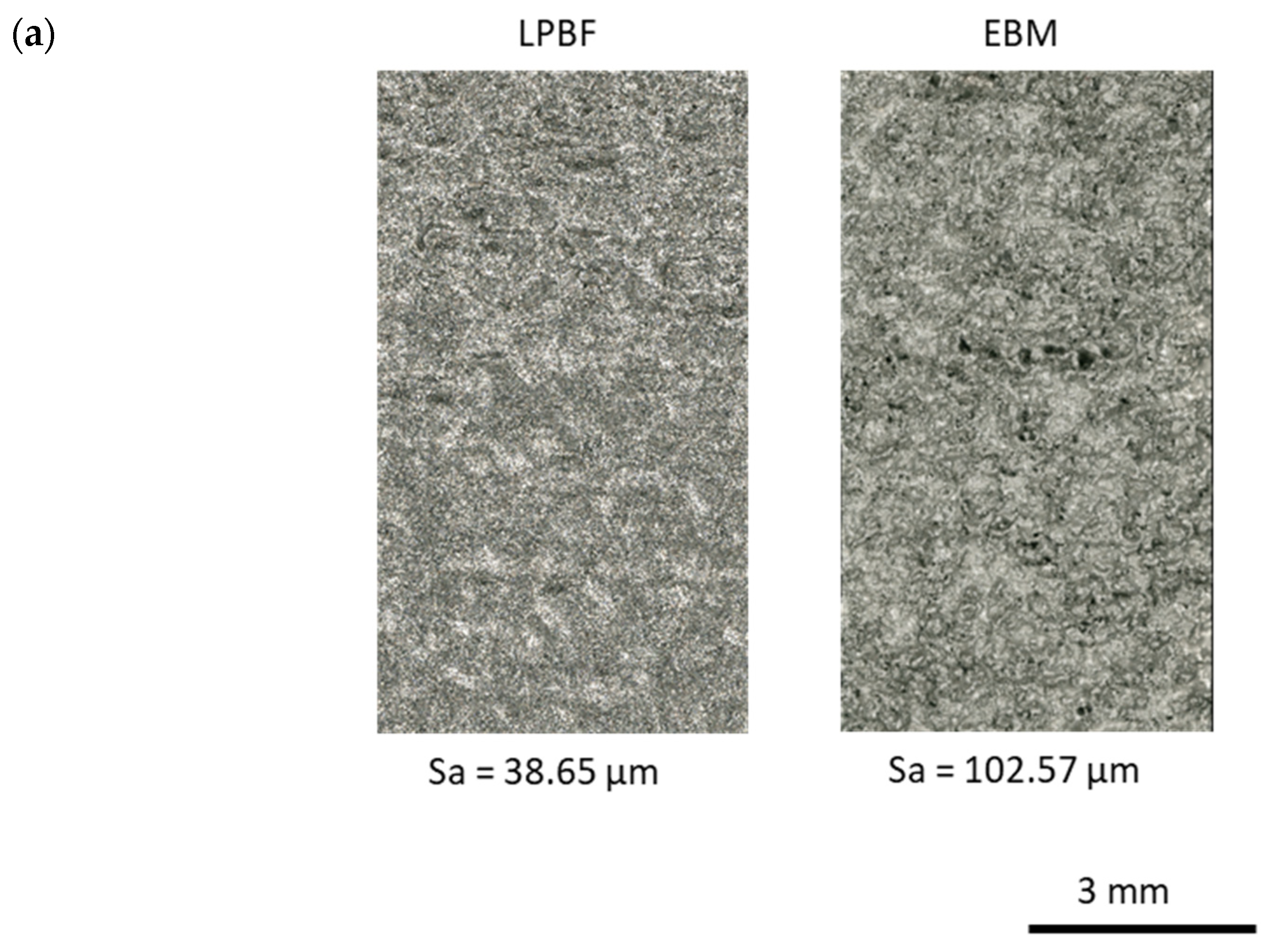
3.5. Roughness
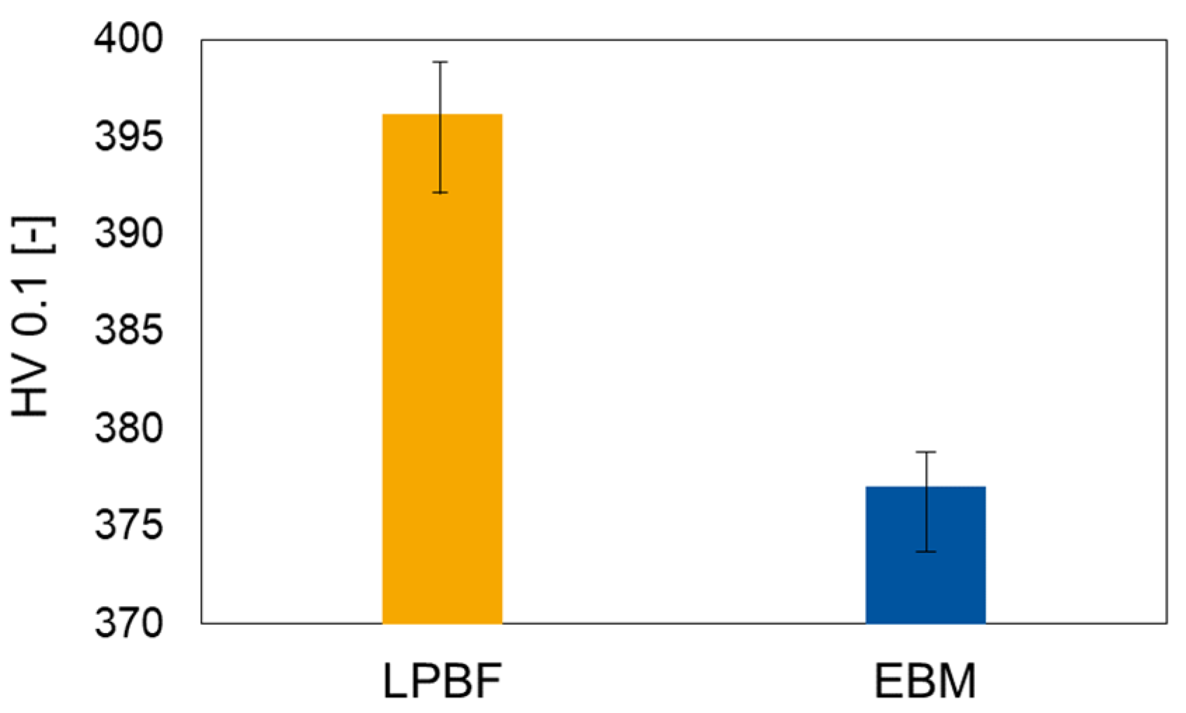
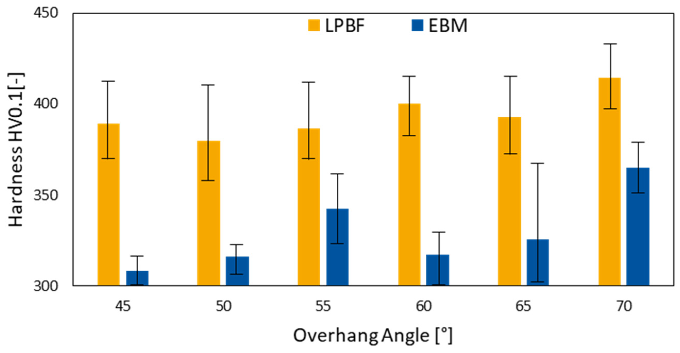
3.6. Hardness
4. Conclusions and Outlook
- It has been found that the volume energy density is similar for both LPBF and EBM when absorption is considered.
- While the relative density showed no significant difference, similar results for the surface roughness, melt-pool dimensions, and hardness could not be achieved in LPBF and EBM when manufactured with a similar volume energy density.
- The energy density is not sufficient to guarantee a similar component quality.
- The main reasoning is assumed to be the significant difference in the preheating strategy in LPBF and EBM.
- Similar preheating strategies in LPBF, such as the use of VCSELs [50], are required to achieve a similar component quality in EBM and LPBF.
- The volume energy density and different preheating strategies should be investigated in future studies to understand the possibility of process transferability.
Author Contributions
Funding
Institutional Review Board Statement
Informed Consent Statement
Data Availability Statement
Conflicts of Interest
References
- Grasso, M.; Colosimo, B.M. Process defects and in situ monitoring methods in metal powder bed fusion: A review. Surf. Topogr. Metrol. Prop. 2017, 28, 44005. [Google Scholar] [CrossRef] [Green Version]
- Tosi, R.; Leung, C.L.A.; Tan, X.; Muzangaza, E.; Attallah, M.M. Revealing the microstructural evolution of electron beam powder bed fusion and hot isostatic pressing Ti-6Al-4V in-situ shelling samples using X-ray computed tomography. Addit. Manuf. 2022, 57, 102962. [Google Scholar] [CrossRef]
- Fox, J.C.; Moylan, S.P.; Lane, B.M. Effect of Process Parameters on the Surface Roughness of Overhanging Structures in Laser Powder Bed Fusion Additive Manufacturing. Procedia CIRP 2016, 45, 131–134. [Google Scholar] [CrossRef] [Green Version]
- Frazier, W.E. Metal Additive Manufacturing: A Review. J. Mater. Eng. Perform. 2014, 23, 1917–1928. [Google Scholar] [CrossRef]
- Caprio, L.; Chiari, G.; Demir, A.G.; Previtali, B. Development of Novel High Temperature Laser Powder Bed Fusion System for the Processing of Crack-Susceptible Alloys. In Proceedings of the the 29th Annual International Solid Freeform Fabrication (SFF) Symposium—An Additive Manufacturing Conference, Austin, TX, USA, 13–15 August 2018; pp. 2275–2285. [Google Scholar]
- Reijonen, J.; Revuelta, A.; Riipinen, T.; Ruusuvuori, K.; Puukko, P. On the effect of shielding gas flow on porosity and melt pool geometry in laser powder bed fusion additive manufacturing. Addit. Manuf. 2020, 32, 101030. [Google Scholar] [CrossRef]
- Agius, D.; Kourousis, K.; Wallbrink, C. A Review of the As-Built SLM Ti-6Al-4V Mechanical Properties towards Achieving Fatigue Resistant Designs. Metals 2018, 8, 75. [Google Scholar] [CrossRef] [Green Version]
- Allmen, M.v.; Blatter, A. Laser-Beam Interactions with Materials; Springer: Berlin, Heidelberg, 1995; ISBN 978-3-540-59401-7. [Google Scholar]
- Fischer, P.; Romano, V.; Weber, H.P.; Karapatis, N.P.; Boillat, E.; Glardon, R. Sintering of commercially pure titanium powder with a Nd:YAG laser source. Acta Mater. 2003, 51, 1651–1662. [Google Scholar] [CrossRef]
- Tang, H.P.; Qian, M.; Liu, N.; Zhang, X.Z.; Yang, G.Y.; Wang, J. Effect of Powder Reuse Times on Additive Manufacturing of Ti-6Al-4V by Selective Electron Beam Melting. JOM 2015, 67, 555–563. [Google Scholar] [CrossRef]
- Gibson, I.; Rosen, D.; Stucker, B. Additive Manufacturing Technologies: 3D Printing, Rapid Prototyping, and Direct Digital Manufacturing; Springer: New York, NY, USA, 2015. [Google Scholar]
- Edwards, P.; Ramulu, M. Fatigue performance evaluation of selective laser melted Ti–6Al–4V. Mater. Sci. Eng. A 2014, 598, 327–337. [Google Scholar] [CrossRef]
- Körner, C. Additive manufacturing of metallic components by selective electron beam melting—A review. Int. Mater. Rev. 2016, 61, 361–377. [Google Scholar] [CrossRef] [Green Version]
- Scipioni Bertoli, U.; Guss, G.; Wu, S.; Matthews, M.J.; Schoenung, J.M. In-situ characterization of laser-powder interaction and cooling rates through high-speed imaging of powder bed fusion additive manufacturing. Mater. Des. 2017, 135, 385–396. [Google Scholar] [CrossRef]
- Porter, D.A.; Easterling, K.E.; Sherif, M. Phase Transformations in Metals and Alloys, 3rd ed.; Revised Reprint; CRC Press: Hoboken, NJ, USA, 2009; ISBN 9781439883570. [Google Scholar]
- Zhao, X.; Li, S.; Zhang, M.; Liu, Y.; Sercombe, T.B.; Wang, S.; Hao, Y.; Yang, R.; Murr, L.E. Comparison of the microstructures and mechanical properties of Ti–6Al–4V fabricated by selective laser melting and electron beam melting. Mater. Des. 2016, 95, 21–31. [Google Scholar] [CrossRef]
- Liu, S.; Shin, Y.C. Additive manufacturing of Ti6Al4V alloy: A review. Mater. Des. 2019, 164, 107552. [Google Scholar] [CrossRef]
- Lewandowski, J.; Mohsen, S. Metal Additive Manufacturing: A Review of Mechanical Properties. Mater. Res. 2016, 151–186. [Google Scholar] [CrossRef] [Green Version]
- Ataee, A.; Li, Y.; Song, G.; Wen, C. Metal scaffolds processed by electron beam melting for biomedical applications. Metallic Foam Bone; Elsevier: Amsterdam, The Netherlands, 2017; pp. 83–110. ISBN 9780081012895. [Google Scholar]
- Tan, X.; Kok, Y.; Tor, S.B.; Chua, C.K. Application of Electron Beam Melting (EBM) in Additive Manufacturing of an Impeller. In Proceedings of the 1st International Conference on Progress in Additive Manufacturing (Pro-AM 2014), Singapore, 26–28 May 2014; pp. 327–332. [Google Scholar]
- Béraud, N.; Vignat, F.; Villeneuve, F.; Dendievel, R. Improving dimensional accuracy in EBM using beam characterization and trajectory optimization. Addit. Manuf. 2017, 14, 1–6. [Google Scholar] [CrossRef]
- Karlsson, J.; Snis, A.; Engqvist, H.; Lausmaa, J. Characterization and comparison of materials produced by Electron Beam Melting (EBM) of two different Ti–6Al–4V powder fractions. J. Mater. Processing Technol. 2013, 213, 2109–2118. [Google Scholar] [CrossRef]
- Petrovic, V.; Niñerola, R. Powder recyclability in electron beam melting for aeronautical use. Aircr. Eng. Aerosp. Tech. 2015, 87, 147–155. [Google Scholar] [CrossRef]
- Klingvall Ek, R.; Rännar, L.-E.; Bäckstöm, M.; Carlsson, P. The effect of EBM process parameters upon surface roughness. RPJ 2016, 22, 495–503. [Google Scholar] [CrossRef]
- Galati, M.; Minetola, P.; Rizza, G. Surface Roughness Characterisation and Analysis of the Electron Beam Melting (EBM) Process. Materials 2019, 12, 2211. [Google Scholar] [CrossRef] [PubMed] [Green Version]
- Al-Bermani, S.S.; Blackmore, M.L.; Zhang, W.; Todd, I. The Origin of Microstructural Diversity, Texture, and Mechanical Properties in Electron Beam Melted Ti-6Al-4V. Met. Mat. Trans. A 2010, 41, 3422–3434. [Google Scholar] [CrossRef]
- Koike, M.; Martinez, K.; Guo, L.; Chahine, G.; Kovacevic, R.; Okabe, T. Evaluation of titanium alloy fabricated using electron beam melting system for dental applications. J. Mater. Processing Technol. 2011, 211, 1400–1408. [Google Scholar] [CrossRef]
- Antonysamy, A. Microstructure, Texture and Mechanical Property Evolution during Additive Manufacturing of Ti6Al4V Alloy for Aerospace Applications. Ph.D. Thesis, University of Manchester, Manchester, UK, 2012. [Google Scholar]
- Harun, W.S.W.; Manam, N.S.; Kamariah, M.S.I.N.; Sharif, S.; Zulkifly, A.H.; Ahmad, I.; Miura, H. A review of powdered additive manufacturing techniques for Ti-6al-4v biomedical applications. Powder Technol. 2018, 331, 74–97. [Google Scholar] [CrossRef]
- Qian, M.; Xu, W.; Brandt, M.; Tang, H.P. Additive manufacturing and postprocessing of Ti-6Al-4V for superior mechanical properties. MRS Bull. 2016, 41, 775–784. [Google Scholar] [CrossRef] [Green Version]
- Fousová, M.; Vojtěch, D.; Doubrava, K.; Daniel, M.; Lin, C.-F. Influence of Inherent Surface and Internal Defects on Mechanical Properties of Additively Manufactured Ti6Al4V Alloy: Comparison between Selective Laser Melting and Electron Beam Melting. Materials 2018, 11, 537. [Google Scholar] [CrossRef] [PubMed] [Green Version]
- Murr, L.E.; Gaytan, S.M.; Ramirez, D.A.; Martinez, E.; Hernandez, J.; Amato, K.N.; Shindo, P.W.; Medina, F.R.; Wicker, R.B. Metal Fabrication by Additive Manufacturing Using Laser and Electron Beam Melting Technologies. J. Mater. Sci. Technol. 2012, 28, 1–14. [Google Scholar] [CrossRef]
- EOS GmbH. LPBF System EOS M290. Available online: https://docplayer.org/1881544-Technische-beschreibung-eos-m-290-technische-beschreibung-1-eos-m-290-stand-april-2014.html (accessed on 9 July 2022).
- GE Additive. Arcam EBM Q10plus. Available online: https://www.ge.com/additive/sites/default/files/2020-04/EBM_Q10plus_Bro_4_US_EN_v1_0.pdf (accessed on 9 July 2022).
- Sing, S.L.; An, J.; Yeong, W.Y.; Wiria, F.E. Laser and electron-beam powder-bed additive manufacturing of metallic implants: A review on processes, materials and designs. J. Orthop. Res. 2016, 34, 369–385. [Google Scholar] [CrossRef] [PubMed]
- Pobel, C.R.; Osmanlic, F.; Lodes, M.A.; Wachter, S.; Körner, C. Processing windows for Ti-6Al-4V fabricated by selective electron beam melting with improved beam focus and different scan line spacings. RPJ 2019, 25, 665–671. [Google Scholar] [CrossRef]
- Yadroitsev, I.; Krakhmalev, P.; Yadroitsava, I.; Du Plessis, A. Qualification of Ti6Al4V ELI Alloy Produced by Laser Powder Bed Fusion for Biomedical Applications. JOM 2018, 70, 372–377. [Google Scholar] [CrossRef]
- Yasa, E.; Deckers, J.; Kruth, J.-P. The investigation of the influence of laser re-melting on density, surface quality and microstructure of selective laser melting parts. RPJ 2011, 17, 312–327. [Google Scholar] [CrossRef]
- Vandenbroucke, B.; Kruth, J.-P. Selective laser melting of biocompatible metals for rapid manufacturing of medical parts. RPJ 2007, 13, 196–203. [Google Scholar] [CrossRef]
- Wang, D.; Yang, Y.; Zhang, M.; Lu, J.; Liu, R.; Xiao, D. Study on SLM fabrication of precision metal parts with overhanging structures. In Proceedings of the 2013 IEEE International Symposium on Assembly and Manufacturing (ISAM), Xi’an, China, 30 July–2 August 2013; pp. 222–225. [Google Scholar]
- Gruber, S.; Grunert, C.; Riede, M.; López, E.; Marquardt, A.; Brueckner, F.; Leyens, C. Comparison of dimensional accuracy and tolerances of powder bed based and nozzle based additive manufacturing processes. J. Laser Appl. 2020, 32, 32016. [Google Scholar] [CrossRef]
- Thomas, D. The Development of Design Rules for Selective Laser Melting. Ph.D Thesis, University of Wales, National Centre for Product Design & Development Research, Cardiff, UK, 2009. [Google Scholar]
- Di, W.; Yang, Y.; Yi, Z.; Su, X. Research on the fabricating quality optimization of the overhanging surface in SLM process. Int. J. Adv. Manuf. Technol. 2013, 65, 1471–1484. [Google Scholar] [CrossRef]
- Kruth, J.-P.; Bartolo, P.J. Feedback control of selective laser melting. In Proceedings of the 3rd International Conference on Advanced Research in Virtual and Rapid Prototyping, Leiria, Portugal, 24–29 September 2007; pp. 521–527. [Google Scholar]
- Chen, Z.; Wu, X.; Tomus, D.; Davies, C.H.J. Surface roughness of Selective Laser Melted Ti-6Al-4V alloy components. Addit. Manuf. 2018, 21, 91–103. [Google Scholar] [CrossRef]
- Grünewald, J.; Clarkson, P.; Salveson, R.; Fey, G.; Wudy, K. Influence of Pulsed Exposure Strategies on Overhang Structures in Powder Bed Fusion of Ti6Al4V Using Laser Beam. Metals 2021, 11, 1125. [Google Scholar] [CrossRef]
- Yadroitsev, I.; Krakhmalev, P.; Yadroitsava, I. Titanium Alloys Manufactured by In Situ Alloying During Laser Powder Bed Fusion. JOM 2017, 69, 2725–2730. [Google Scholar] [CrossRef]
- Hrabe, N.; Quinn, T. Effects of processing on microstructure and mechanical properties of a titanium alloy (Ti–6Al–4V) fabricated using electron beam melting (EBM), Part 2: Energy input, orientation, and location. Mater. Sci. Eng. A 2013, 573, 271–277. [Google Scholar] [CrossRef]
- Cao, S.; Zou, Y.; Voon Samuel Lim, C.; Wu, X.; Cao, S.; Zou, Y.; Wu, X. Review of laser powder bed fusion (LPBF) fabricated Ti-6Al-4V: Process, post-process treatment, microstructure, and property. Light Adv. Manuf. 2021, 2, 313–332. [Google Scholar] [CrossRef]
- Vogelpoth, A. VCSEL Preheating for Laser Powder Bed Fusion. Available online: https://webcache.googleusercontent.com/search?q=cache:XUbsnUliUXkJ:https://www.ilt.fraunhofer.de/content/dam/ilt/en/documents/annual_reports/AR18/TF2/AR18_P54_VCSEL_preheating_for_laser_powder_bed_fusion.pdf+&cd=4&hl=de&ct=clnk&gl=de&client=firefox-b-d (accessed on 28 July 2022).


| Machine Characteristics | LPBF System | EBM System |
|---|---|---|
| Heat Source | Yb fibre-laser | Single crystalline |
| Build Volume [mm] | ||
| Max. Beam Power [W] | 400 | 3000 |
| Atmosphere | Argon | Vacuum |
| Spot Size [µm] | 100 | 140 |
| Max. scan speed [m/s] | 7 | 8000 |
| Max. preheating temperature [°C] | 200 | 1100 |
| Parameter \ Process | LPBF | EBM |
|---|---|---|
| Heat Source Power [W] | 300 (Laser) | 1500 (Electron Beam) |
| Scan Speed [mm/s] | 1000 | 6000 |
| Hatch Distance [mm] | 0.1 | 0.2 |
| Layer thickness [mm] | 0.05 | 0.05 |
| Volume Energy Density [J/mm3] * | 60 | 25 |
| Parameter | LPBF | EBM |
|---|---|---|
| Heat Source Power, PB [W] | 300 (Laser) | 1500 (Electron Beam) |
| Scan Speed, vscan [mm/s] | 1000 | 6000 |
| Melt Pool Radius, t/2 [mm] | 0.07 | 0.122 |
| Melt Pool Depth, d [mm] | 0.16 | 0.25 |
| Volume Energy Density, EV (calculated according to Equation (1)) [J/mm3] | 26.79 | 8.2 |
| Heat Source Absorption [%] | 40 | 98 |
| Volume Energy Density, EV (calculated according to Equation (1) and considering absorption) [J/mm3] | 10.7 | 8.04 |
| Ti6Al4V Heat Capacity, cp [J/g × K] | 0.7 | - |
| Powder Bed Density, [mg/mm3] | 2.121 | - |
| Temperature difference, [K] | 953.15 | - |
| Real Volume Energy Density, EV (Equation (1)–Equation (2)) [J/mm3] | 9.28 | 8.04 |
Publisher’s Note: MDPI stays neutral with regard to jurisdictional claims in published maps and institutional affiliations. |
© 2022 by the authors. Licensee MDPI, Basel, Switzerland. This article is an open access article distributed under the terms and conditions of the Creative Commons Attribution (CC BY) license (https://creativecommons.org/licenses/by/4.0/).
Share and Cite
Megahed, S.; Aniko, V.; Schleifenbaum, J.H. Electron Beam-Melting and Laser Powder Bed Fusion of Ti6Al4V: Transferability of Process Parameters. Metals 2022, 12, 1332. https://doi.org/10.3390/met12081332
Megahed S, Aniko V, Schleifenbaum JH. Electron Beam-Melting and Laser Powder Bed Fusion of Ti6Al4V: Transferability of Process Parameters. Metals. 2022; 12(8):1332. https://doi.org/10.3390/met12081332
Chicago/Turabian StyleMegahed, Sandra, Vadim Aniko, and Johannes Henrich Schleifenbaum. 2022. "Electron Beam-Melting and Laser Powder Bed Fusion of Ti6Al4V: Transferability of Process Parameters" Metals 12, no. 8: 1332. https://doi.org/10.3390/met12081332