
70 Years of LD-Steelmaking—Quo Vadis?


Abstract
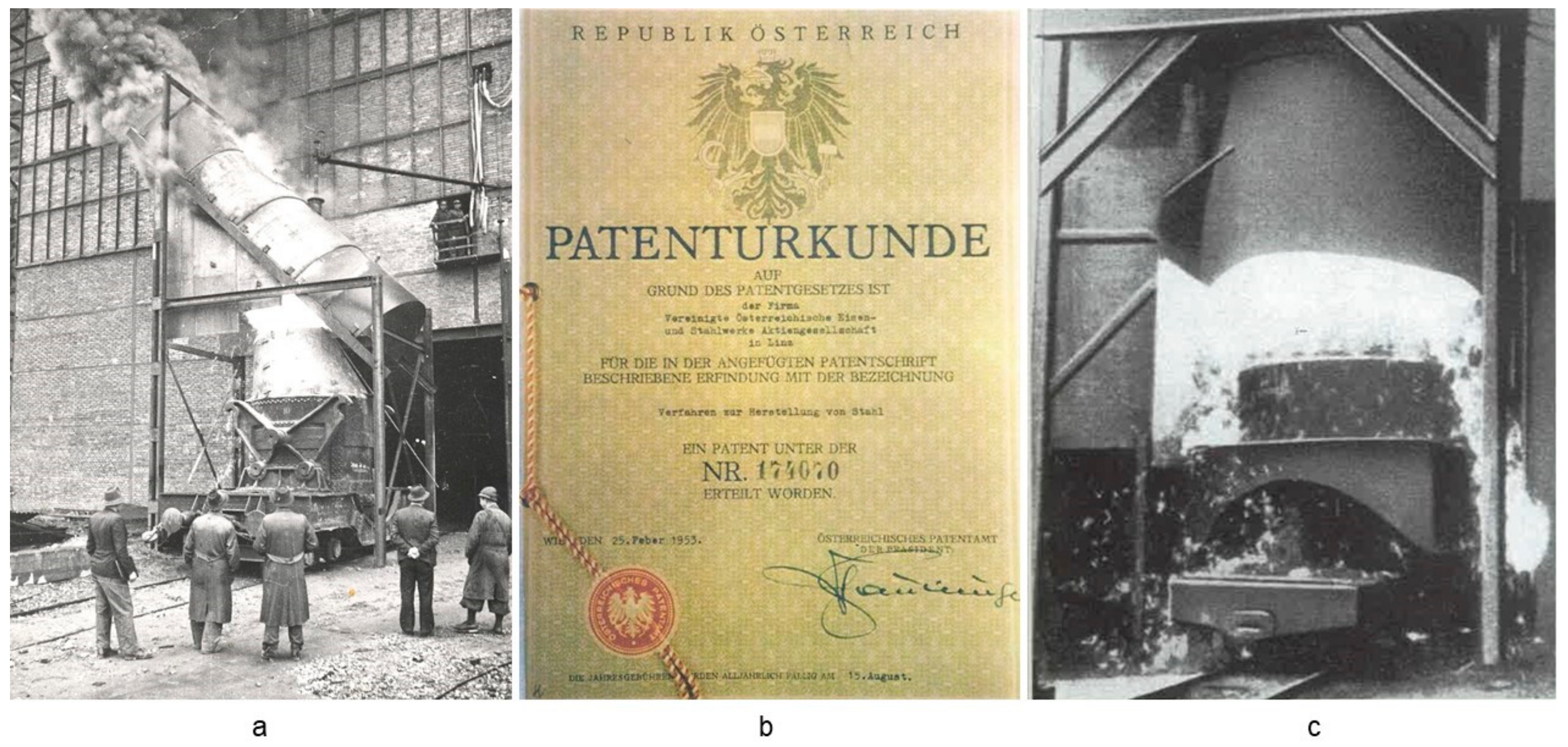
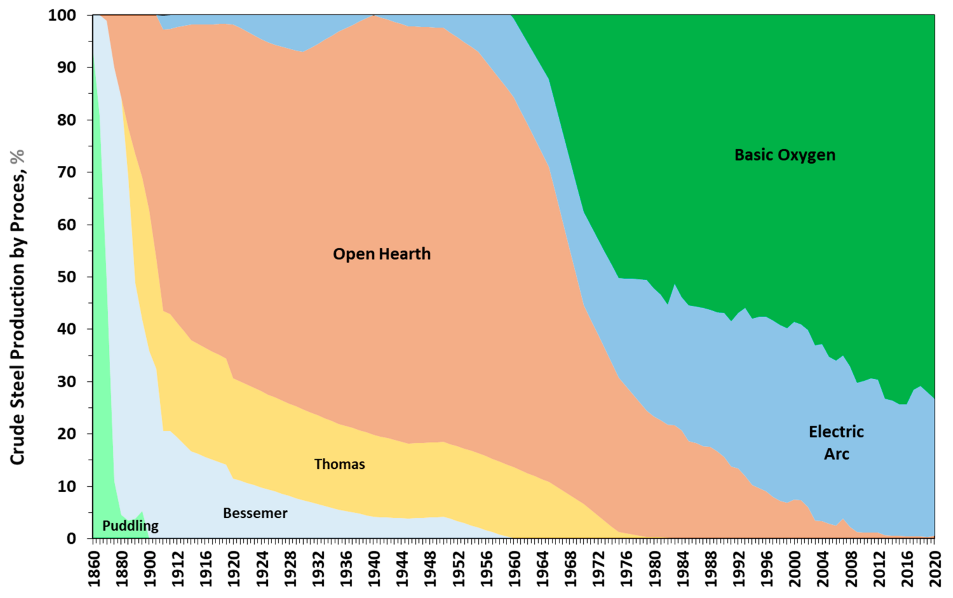
:1. How It Started
2. State-of-the-Art in Technology
2.1. Converter Equipment
2.2. Blowing Process
2.3. Bottom-Purging
2.4. Endpoint Detection
2.5. Tapping
2.6. Off-Gas Cleaning
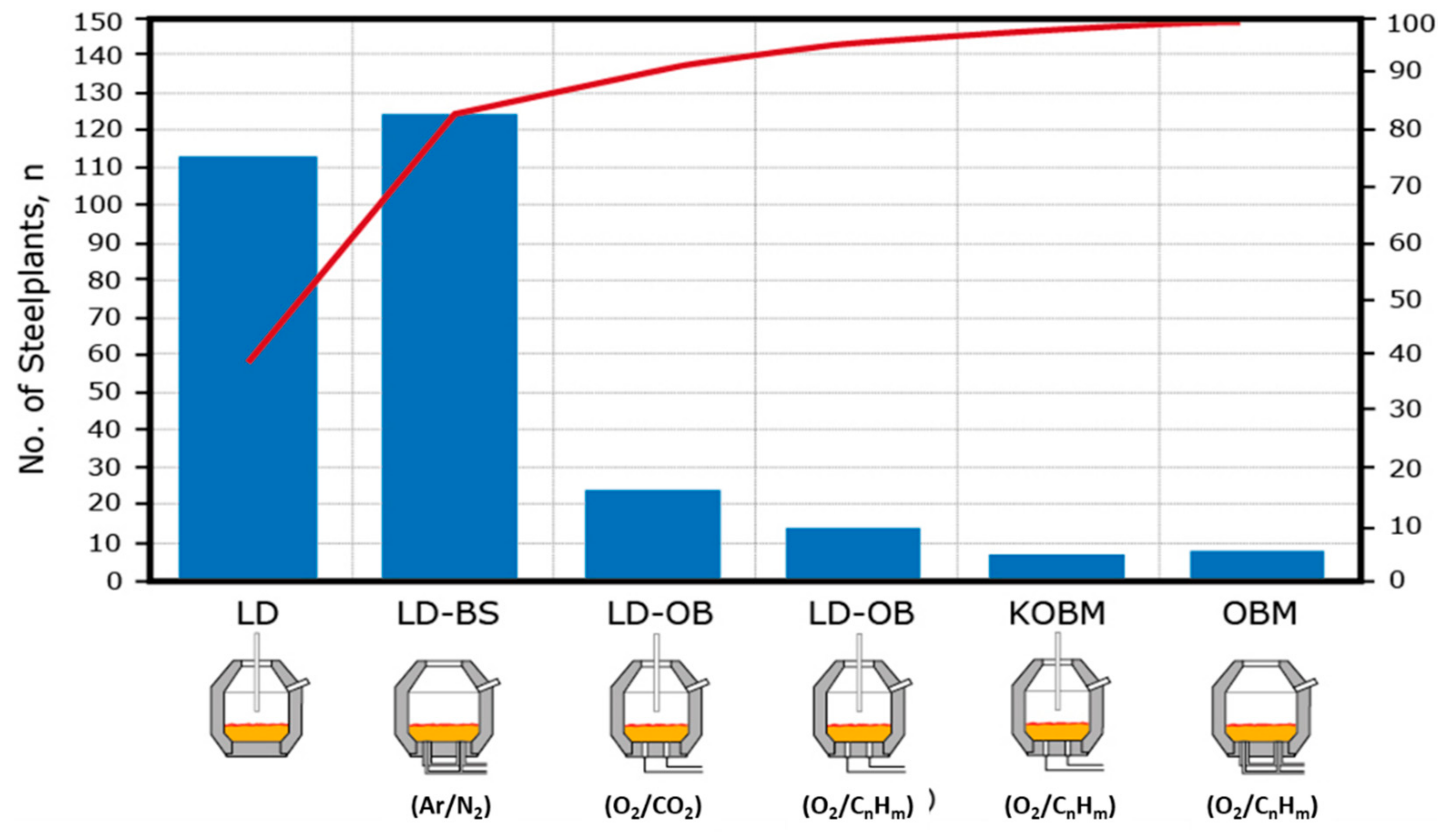
3. Worldwide Operation Practices Applied
3.1. Straight Blow Practice
3.2. Blow-Splash Practice
- Blowing lance skulling;
- Skulling of the vessel mouth;
- Blocking of bottom stirring plugs/tuyeres (by bottom built-up);
- Limited efficiency of the hot face residual brick thickness measurement by lasers;
- Higher sensitivity for slopping/spitting;
- Cycle time losses for splashing, inspection and refractory maintenance;
- Yield losses (change in vessel profile);
- Poor metallurgical slag properties for de-phosphorization.
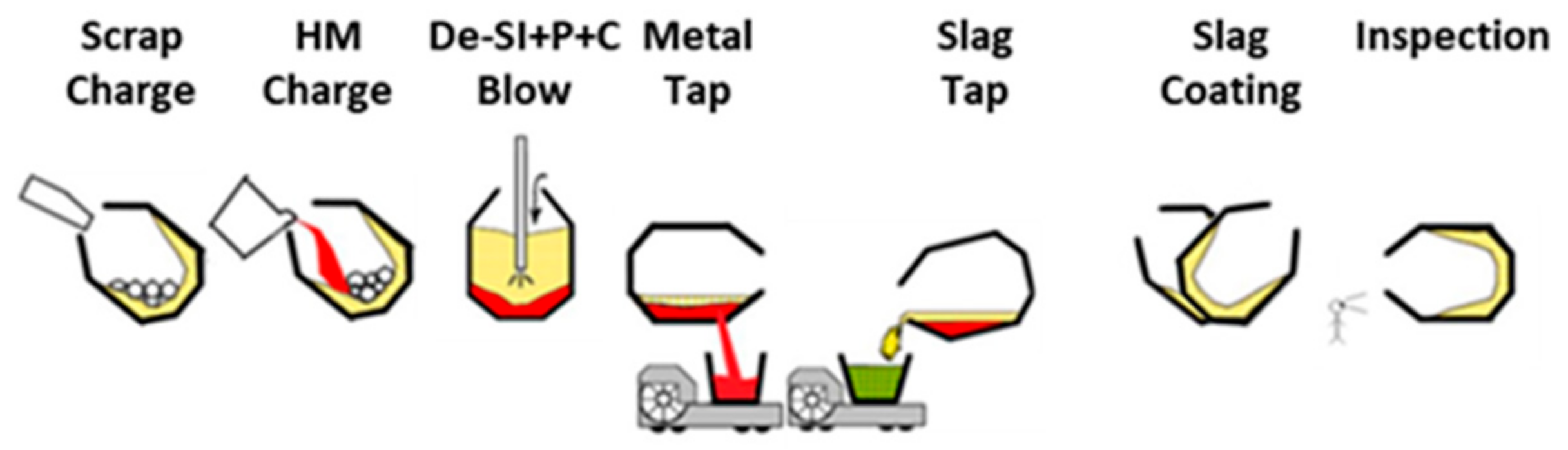
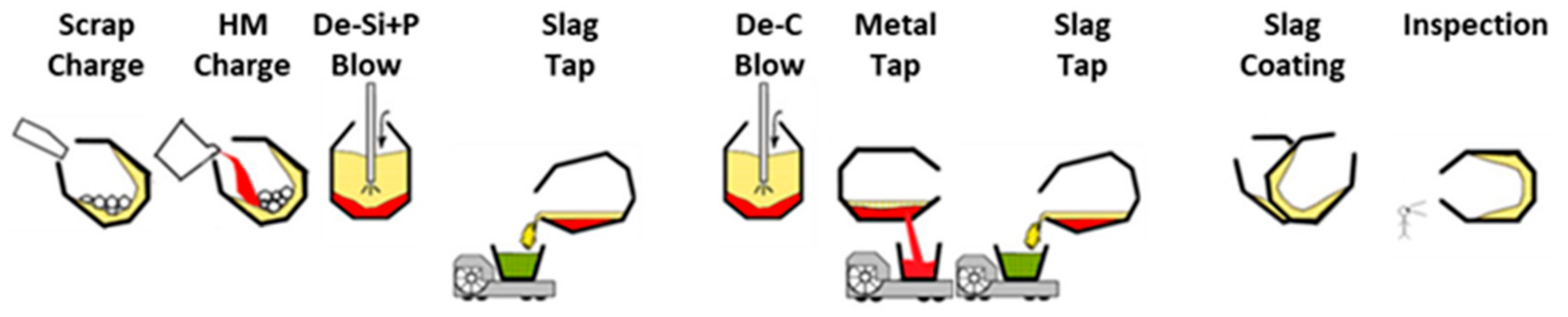
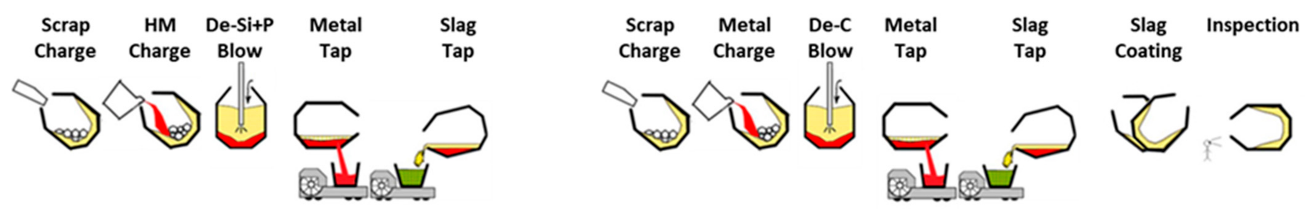
3.3. Double-Slag Practice
- (a)
- Straight-blow: for final [%P] 0.015–0.025% (47%): 35 min/heat; improvement of slag volume by using recycled LD-slag/ladle slag in charge, in case of liquid recycling temperature, and FeO content must be decreased.
- (b)
- Double-slag: for final [%P] 0.015–0.025% (51%) and 0.008–0.012% (2%): 45 min/heat operation time.
- (c)
- 2-vessel-double-slag: for final [%P] is 0.005–0.008: 1st heat: 34 min/heat + 2nd heat: 28 min/heat = 62 min/heat; increased Fe-yield.
4. LD-Process towards Reliable, Safe, and Sustainable Steel Production
- (a)
- Reducing the impact of steel production;
- (b)
- Efficiency and the circular economy;
- (c)
- Developing advanced steel products to enable societal transformations [57].
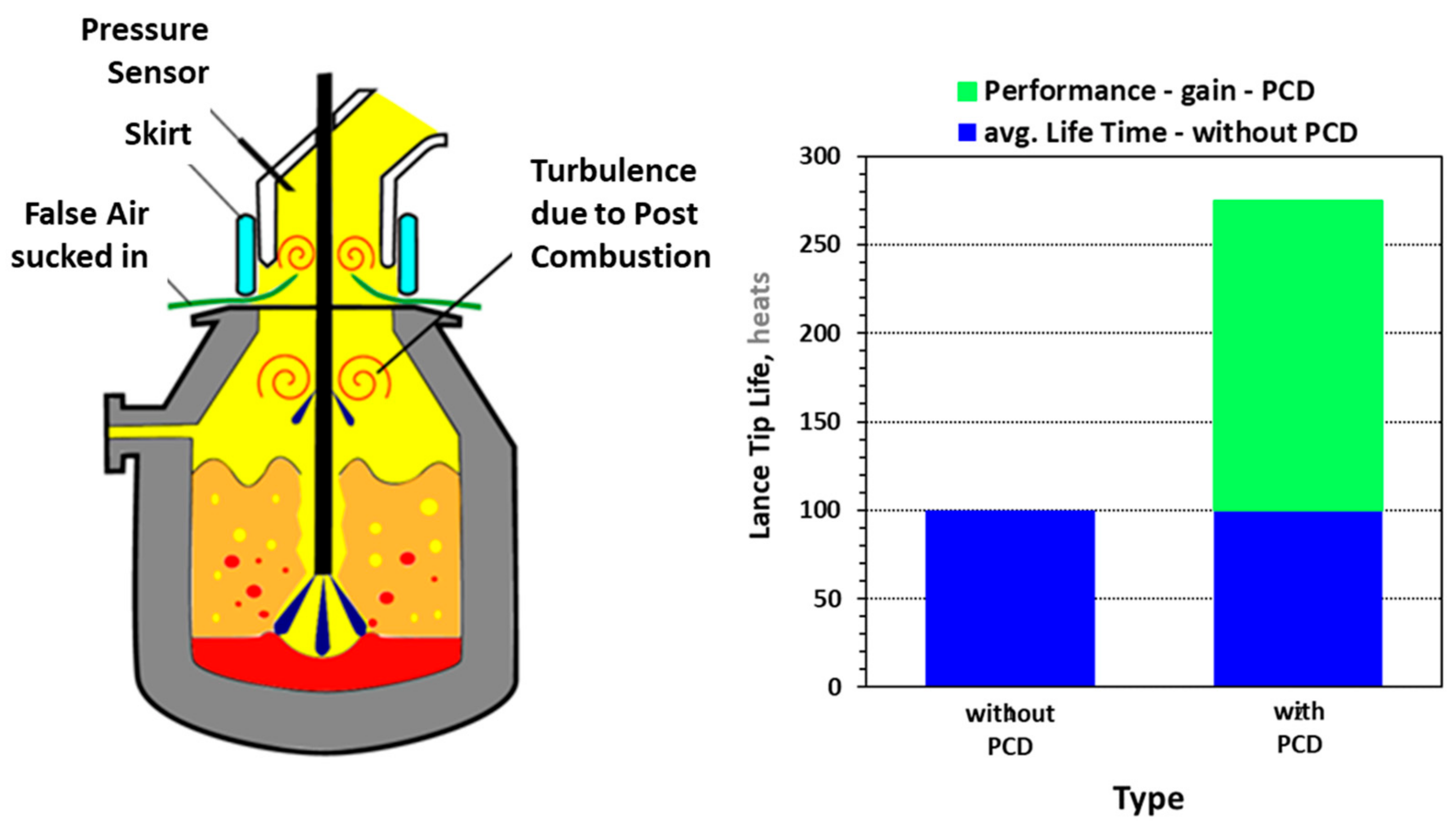
4.1. Increase of Scrap Rate
- (a)
- The scrap rate can be increased by 0.34% with a 1.0% increase in the degree of post-combustion.
- (b)
- With a degree of post-combustion between 10 and 20%, around 70% of the heat of the reaction can be transferred to the metal bath and the slag.
4.2. Use of By-Products
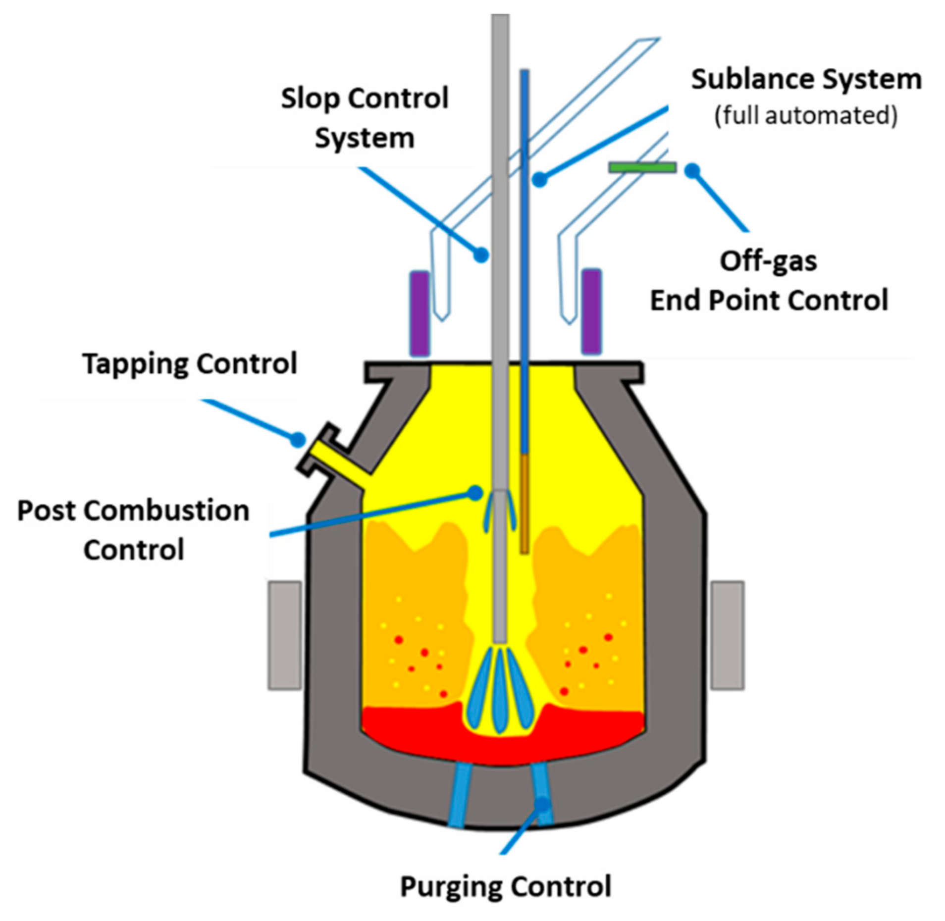
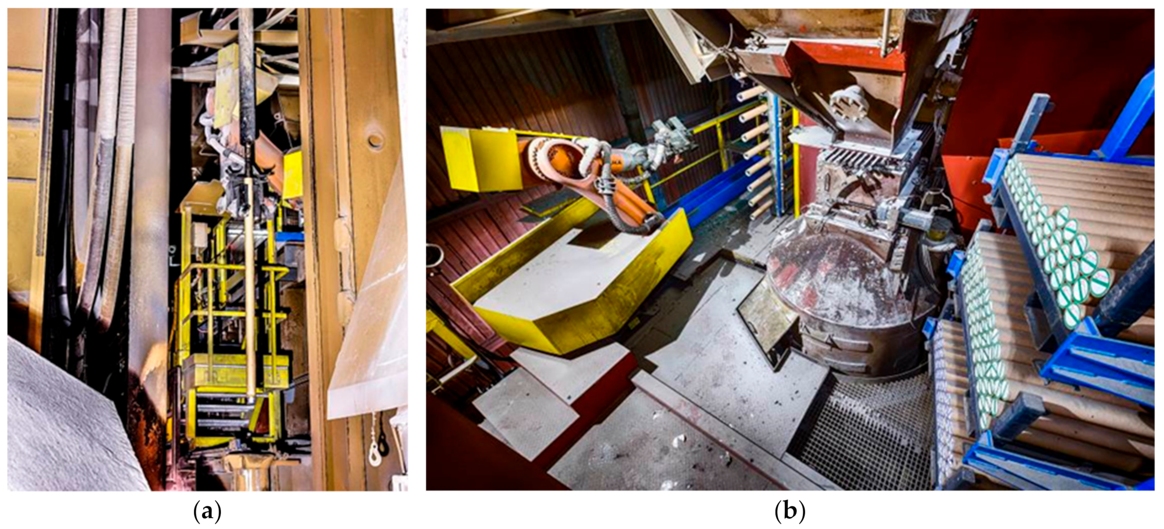
4.3. Process Automation
5. Future Aspects of LD-Steelmaking
- (a)
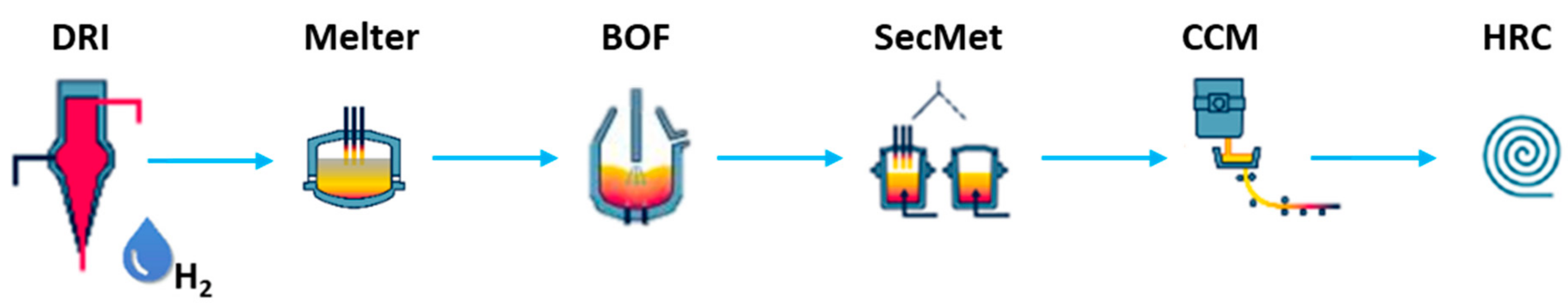
- It is immediately evident that the LD concept allows continued operation of existing melt shops and subsequent continuous casting and rolling. Fewer investment costs for a transition of existing sites are one of the important consequences. All investment into existing integrated sites can concentrate on Electric-Hot-Metal production.
- (b)
- Continuous casting of slabs is known to deliver the best available surface qualities, and it is still unclear if mini-mill concepts with EAFs can close this gap in the far future. Therefore, keeping existing steel mills and integrated sites is superior to a new investment in a mini-mill concept.
- (c)
- When it comes to chemical composition, the LD converter can play to its strengths within the new configuration: lowest phosphorous and lowest nitrogen, especially combinations of lowest carbon and lowest nitrogen. The LD converter will continue to enable the most sophisticated chemical compositions for the final steel product. Metallurgical experts are well aware that the ability to “repair” chemical composition within the secondary metallurgy is limited.
- (d)
- The melting step is stripped from unnecessary metallurgical work. Robust equipment that follows the idea of submerged-arc furnaces run under a reducing atmosphere and offers some unique opportunities in raw materials that are not part of EAF steelmaking. Certainly most important is that there is no need to use DR grade pellets as feedstock inside the DR plant as there is no need for a foaming slag within the melting aggregate. Availability of DR grade pellets is already a topic today and is likely to get worse in the future. Besides directly reduced iron, iron-bearing recycling material can also be introduced, and even scrap can be added. The subsequent slag from this process step can be handed over to the cement industry, as happens today with blast furnace slag.
- (e)
- Finally, the LD-process will form a completely new production chain in combination with new upstream processes. This new route offers opportunities to deal with fluctuations in energy supply much better than the traditional combination with blast furnaces did. While this aspect is mainly irrelevant today, it might be decisive in a “fossil-free” future.
6. Summary
Author Contributions
Funding
Institutional Review Board Statement
Informed Consent Statement
Data Availability Statement
Conflicts of Interest
References
- Kreulitsch, H.; Krieger, W.; Antliger, K.; Jungreithmeier, A. Der LD-Prozess ein Ökologisch Optimiertes Verfahren; Neue Hütte: Schmalkalden, Germany, 1992; Volume 37, pp. 313–320. [Google Scholar]
- Stein-Versen, R. 40 Jahre LD-Verfahren. Stahl Eisen 1992, 112, 72–79. [Google Scholar]
- Durrer, R.; Hellbrügge, H.; Richter-Brohm, H. Die Entstehung des LD-Sauerstoffaufblas-Verfahrens. Stahl Eisen 1965, 85, 1751–1754. [Google Scholar]
- Kalla, U.; Kreutzer, W. Entwicklungsrichtungen in der Stahlerzeugung. Stahl Eisen 1970, 90, 1146–1154. [Google Scholar]
- Habashi, F. Pioneers of the Steel Industry: Part 7 Oxygen in Steelmaking. Steel Times Int. Jan./Febr. 2012, 44. [Google Scholar]
- ASME. Oxygen Process Steelmaking Vessel; ASME Publication: New York, NY, USA, 1985. [Google Scholar]
- Gebert, W.; Müller, J.; Hiebler, M. Worldwide Trends and Development in LD Converter Steelmaking. In Proceedings of the IS’06–Siemens VAI’s Iron and Steelmaking Conference, Linz, Austria, 9–11 October 2006. [Google Scholar]
- Werk Donawitz Entwicklung und Umfeld 50 Jahre LD-Verfahren; Voestalpine Bahnsystem GmbH: Munchen, Germany, 2002.
- Trenkler, H. 20 Jahre LD-Verfahren. Stahl Eisen 1972, 92, 709–716. [Google Scholar]
- Stone, J.K. The Origins of Modern Oxygen Steelmaking. Steel Times 2000, 228, 328–330. [Google Scholar]
- Hiebler, H. Entwicklung und Stand des LD-Verfahrens. Metalurgija 2002, 41, 157–164. [Google Scholar]
- Schober, M. Die Geschichte des Linz-Donawitz-Verfahrens; Voestalpine, A.G., Ed.; Corporate Communications: Munchen, Germany, 2012; pp. 1–44. [Google Scholar]
- Fritz, E.; Gebert, W.; Ramaseder, N. Converter Steelmaking with Emphasis on LD Technology. BHM 2002, 147, 5. [Google Scholar]
- Wallner, F.; Fritz, E. Fifty years of Oxygen-Converter Steelmaking. Rev. Met. Paris 2002, 99, 825–837. [Google Scholar] [CrossRef]
- Krieger, W. 50 Jahre LD-Prozess—50 Jahre Innovation, Teil 1. BHM 2003, 148, 247–253. [Google Scholar]
- Krieger, W. 50 Jahre LD-Prozess—50 Jahre Innovation, Teil 2. BHM 2003, 148, 427–431. [Google Scholar]
- Presslinger, H. 50 Jahre LD-Verfahren—Ein Blick in die 40er- und 50er Jahre. Stahl Eisen 2003, 123, 103–104. [Google Scholar]
- Fritz, E.; Gebert, W. Milestones and Challenges in Oxygen Steelmaking; Canadian Metallurgical Quarterly: Milton, UK, 2005; pp. 249–260. [Google Scholar]
- Höfer, W.; Auberger, E.; Apfolterer, R.; Exenberger, R.; Ebner, K. Converter Vessel exchange at voestalpine Stahl GmbH in Linz. In Proceedings of the EOSC Proceeding, Stockholm, Sweden, 7–9 September 2011. [Google Scholar]
- Zuliani, D.; Scipolo, V. iBOF® Technology Improves BOF Process Control, Endpoint Detection and Slop Mitigation. In Proceedings of the AISTech Proceeding, Pittsburgh, PA, USA, 16–19 May 2016. [Google Scholar]
- Torok, S.; Wimmer, G.; Unterrainer, G.; Vailancourt, D. Revamp of BOF Converters at AK Steel-Middletown Works Using Vaicon Link 2.0 Converter Vessel Suspension System. In Proceedings of the AISTech Proceeding, Cleveland, OH, USA, 31 August–2 September 2020. [Google Scholar]
- Demuner, L.; Voraberger, B.; Correa, W.; Wimmer, G. Increased Safety and Performance of BOF Relining at Ternium Brasil. In Proceedings of the AISTech Proceeding, Nashville, TN, USA, 29 June–1 July 2021. [Google Scholar]
- Wimmer, E.; Schwaha, R.; Wimmer, G. Optimization of Converter Design with CFD—Practical application for converter Revamps. In Proceedings of the ESTAD proceeding, Paris, France, 26–29 June 2017. [Google Scholar]
- Külchen, R.; Metzul, A.; Bläser, M. In-situ Laser Gas Measurement at the Converter. In Proceedings of the EOSC Proceeding, Trinec, Czech Republic, 9–11 September 2014. [Google Scholar]
- Panhofer, H.; Egger, M.W.; Strelbisky, M. First Operating Experiences with Post-Combustion Lances at BOF shop LD3. In Proceedings of the ESTAD Proceeding, Dusseldorf, Germany, 15–19 June 2015. [Google Scholar]
- Lehner, J.; Egger, M.W.; Panhofer, H.; Strelbisky, M. First Operating Experiences with Post-Combustion Lances at BOF shop LD3. In Proceedings of the ESTAD Proceeding, Vienna, Austria, 26–29 June 2017. [Google Scholar]
- Wimmer, G.; Ke, J.W.; Dimitrov, S.; Voraberger, B. Increase of Scrap Rate in Converter Steelmaking; CSST: Tianjin, China, 2018. [Google Scholar]
- Vazquez, A.; Scipolo, V.; Zuliani, D. Effective Detection of Slopping Events for Improved BOF Performance and Reduction of GHG Emissions. In Proceedings of the EOSC Proceeding, Trinec, Czech Republic, 9–11 September 2014. [Google Scholar]
- Odenthal, H.-J.; Grygorov, P.; Refferscheid, M.; Schlüter, J. Advanced Blowing and Stirring Conditions in the BOF Process. In Proceedings of the AISTech Proceeding, Pittsburg, PA, USA, 6–9 May 2013; pp. 897–909. [Google Scholar]
- Hubmer, R.; Hofinger, S.; Hiebler, M.; Kühböck, H. Latest Generation of Automation Solutions for BOF Converters. In Proceedings of the EOSC Proceeding, Trinec, Czech Republic, 9–11 September 2014. [Google Scholar]
- Carvalho, D. BOF Process Optimization and Technology Improvements at Ternium Brazil. In Proceedings of the AISTech Proceeding, Pittsburgh, PA, USA, 6–9 May 2019. [Google Scholar]
- Egger, M.W.; Priesner, A.; Lehner, J.; Nogratnig, H.; Lechner, H.; Wimmer, G. Successful revamp of sublance manipulators for the LD converters at voestalpine Stahl GmbH: Operational experience gained in the first year. In Proceedings of the AISTech Proceeding, Pittsburgh, PA, USA, 16–19 May 2016. [Google Scholar]
- Gerstorfer, G.; Keplinger, T.; Priesner, A.; Sedivy, C.; Traxinger, H.; Vorarberger, B.; Watzinger, S. Robotic applications continuously enhancing safety in melt shops. In Proceedings of the EOSC Proceeding, Taranto, Italy, 10–12 October 2018. [Google Scholar]
- Cuypers, J.; Vergauwnes, M.; Beyens, D.; Maenhoudt, M. QuiK-Spec Multi-Lance Probe for inblow and endblow application: Your critical link to a fast converter sample analysis. In Proceedings of the AISTech Proceeding, Pittsburgh, PA, USA, 6–9 May 2019. [Google Scholar]
- Serrano, E.; Wimmer, G.; Runner, D.; Li, Y.; Vaillancourt, D.; Maringer, M. Installation of Vaicon Slag Stopper at U.S. Steel—Great Lakes Works. In Proceedings of the AISTech Proceeding, Cleveland, OH, USA, 31 August–2 September 2020. [Google Scholar]
- Thomasberger, J.; Premanand, K.; Kuczora, R.; Linden, W. Experience on Automatic BOF Tapping in a European Steel Plant. In Proceedings of the EOSC Proceeding, Taranto, Italy, 10–12 October 2018. [Google Scholar]
- Linden, W.; Reichel, J. Automatic Tapping at BOF Converters. In Proceedings of the EOSC Proceeding, Trinec, Czech Republic, 9–11 September 2014. [Google Scholar]
- Messina, C.J.; Paules, J.R. The worldwide Status of BOF Slag Splashing Practices and Performance. In Proceedings of the 79th Steelmaking Conference, Pittsburgh, PA, USA, 24–27 March 1996; pp. 153–155. [Google Scholar]
- Goodson, K.; Donaghy, N.; Russel, R. Furnace Refractory Maintenance and Slag Splashing; Iron & Steelmaker: Warrendale, PA, USA, 1995; Volume 22, pp. 31–35. [Google Scholar]
- Messina, C.J. Slag Splashing in the BOF—Worldwide Status, Practices and Results; Iron and Steel Engineer: Pittsburgh, PA, USA, 1996; Volume 5, pp. 17–19. [Google Scholar]
- Holzhey, W.; Kruschke, E.; Daum, T.; Müller, K. Slag Splashing—An Efficient Means of Reducing Refractory Cost. In Oxygen Steelmaking Session; ISC98: Linz, Austria, 1998; pp. 1–5. [Google Scholar]
- Camelli, S.; Brandaleze, E.; Madias, J.; Topolevsky, R. Protection of Converter Lining with Slag Adherence Mechanism. In Proceedings of the XXXIII Seminário de Fusão, Refino e Solidificação dos Metais, Santos, Brasil, 6–8 May 2001. [Google Scholar]
- Junger, H.J.; Jandl, C.; Cappel, J. Relationship between BOF maintenance strategies and steelmaking productivity. Iron Steel Technol. 2008, 11, 29–35. [Google Scholar]
- Gark, A.K.; Peaslee, K.D. Physical Modeling of Slag Splashing. In Proceedings of the Steelmaking Conference Proceedings, Chicago, IL, USA, 13–16 April 1997; pp. 87–96. [Google Scholar]
- Mills, K.C.; Su, Y.; Fox, A.B.; Li, Z.; Thacray, R.P.; Tsai, H.T. A Review of Slag Splashing. ISIJ Int. 2005, 45, 619–633. [Google Scholar] [CrossRef] [Green Version]
- Chigwedu, C.; Kempken, J. Splashing for low gunning rates. In Proceedings of the AISTec2006 Conference Proceedings, Cleveland, OH, USA, 1–4 May 2006. [Google Scholar]
- Amoss, D.L. BOF Steelmaking Converter Lives (2000 to 40,000). In Proceedings of the The Southern African Institute of Mining and Metallurgy, Refractories 2010 Conference, Johannesburg, South Africa, 16–17 March 2010; pp. 137–152. Available online: https://www.saimm.co.za/Conferences/Refractories2010/137-152_Amoss.pdf (accessed on 12 February 2022).
- Trentini, A.; Allard, M. Steelmaking by Injection of Oxygen and Lime Powder IRSID-O.L.P. Process. Indian Constr. News 1959, 186–190. [Google Scholar]
- Berve, J. Schlackenarmes Frischen im LD-Konverter, Kommission der Europäischen Gemeinschaften. Technische Forschung Stahl, Abschlussbericht; EUR 10520 DE. 1986. Available online: https://op.europa.eu/en/publication-detail/-/publication/fbab7892-18e6-4e6d-bf82-b200e2f202a0 (accessed on 12 February 2022).
- Wiemer, H.E.; Delhey, H.M.; Sperl, H.; Weber, R.A. Verfahrenstechniken und metallurgische Ergebnisse der Blasstahlerzeugung in der Bundesrepublik Deutschland. Stahl Eisen 1985, 105, 1142–1148. [Google Scholar]
- Yamauchi, H.; Murayama, N.; Katoh, K.; Onoyama, S.; Fukuda, Y.; Ina, M. Improvement of BOF Productivity by using pre-treated Hot Metal at Nagoya Works. In Proceedings of the 1st European Oxygen Steelmaking Congress, Dusseldorf, Germany, 21–23 June 1993; VDEH: Dusseldorf, Germany, 1993. [Google Scholar]
- Aoki, J. Hot Metal Pretreatment in a Converter at Muroan Works. In Proceedings of the 10th HKM-NSC Technical Meeting, Huckingen, Germany; 2000. [Google Scholar]
- Keum, C.H.; Park, J.M.; Kim, J.S.; Choi, C.H. Optimization of HM-De-P and BOF Refining at POSCO Gwagyang Steelworks. In Proceedings of the 4th European Oxygen Steelmaking Conference, Graz, Austria, 12–15 May 2003. [Google Scholar]
- Othsuka, M.; Iwata, K. The progressive Refining Technologies in new Steelmaking Shop at Wakayama Works. In Proceedings of the 4th European Oxygen Steelmaking Conference, Graz, Austria, 12–15 May 2003. [Google Scholar]
- Jiang, X.F.; Chen, Z.P.; Lu, Z.X.; Zhang, G.; Zhong, Z.M. Development and Application of BRP Technology in Baosteel. Metall. Res. Technol. 2007, 104, 29–34. [Google Scholar] [CrossRef]
- Kusada, Y.; Kurai, I.; Sato, K.; Matsuzawa, A.; Kume, K.; Hondo, H. Development to Minimize Iron Loss at Oita Works. In Nippon Steel Technical Report; 2020, Volume 124, pp. 137–148. Available online: https://www.nipponsteel.com/en/tech/report/pdf/124-19.pdf (accessed on 12 February 2022).
- World Steel Association. Policy Paper: Climate Change and the Production of Iron and Steel. Available online: https://worldsteel.org/publications/policy-papers/climate-change-policy-paper/ (accessed on 12 February 2022).
- Brotzmann, K. Verfahren zur Verbesserung der Wärmebilanz beim Stahlfrischen. Patent Office, German Democratic Republic, Patent 140757, 26 March 1980. Available online: https://register.dpma.de/DPMAregister/pat/register?AKZ=DD140757&CURSOR=1 (accessed on 12 February 2022).
- Gruner, H.; Wiemer, E.; Fix, W.D.; Wünnenberg, K. Neue metallurgische Einsichten beim Sauerstoffaufblasverfahren und verbesserte Prozeßkontrolle mit Sublanze und Bodengasspülung. Stahl Eisen 1984, 104, 527–532. [Google Scholar]
- Wiemer, E.; Gruner, H.; Fix, W.D.; Wünnenberg, K. New Metallurgical Insight into BOF-Steelmaking and improved Process Control using Sublance Technique and Bottom Gas Stirring. In Proceedings of the 4th Process Metallurgy Conference, Chicago, IL, USA, 11–14 November 1984; pp. 107–112. [Google Scholar]
- Hirai, M.; Tsujino, R.; Mukai, T.; Harada, T.; Omori, M. Mechanism of Post Combustion in the Converter. Trans. ISIJ 1987, 27, 805–813. [Google Scholar] [CrossRef]
- Sarma, B.; Novak, R.C.; Bermel, C.L. Development of Post-Combustion Practices at Bethlehem Steel’s Burns Harbor Division. In Proceedings of the 1996 Steelmaking Conference Proceedings, Pittsburgh, PA, USA, 24–27 March 1996; pp. 115–122. [Google Scholar]
- Farrand, B.L.; Wood, J.E.; Goetz, F.J. Post Combustion Trials at Dofasco’s KOBM-Furnace. In Proceedings of the Steelmaking Conference Proceedings, Toronto, Canada, 5–8 April 1992; Iron and Steel Society: Warrendale, PA, USA, 1992; Volume 75, pp. 173–179. [Google Scholar]
- Rymarchyk, N.M. Post Combustion Lances in BOF Operations. In Proceedings of the 1998 Steelmaking Conference Proceedings, Toronto, Canada, 22–25 March 1998; pp. 445–450. [Google Scholar]
- Russo, T.; Miller, T.; Repasch, J.; Sheth, N.; Trapp, M. Economic Optimization of BOF Raw Material Consumption in a volatile Scrap Market and limited Hot Metal Availability. In Proceedings of the AISTech 2004 Proceeding, Nashville, TN, USA, 15–17 September 2004; Volume 1, pp. 639–650. [Google Scholar]
- Balkos, T.; Richardson, A.; Russo, T.; Fash, R. Cold Shroud—Boosting Converter Performance. In Proceedings of the AISTech 2005 Proceedings, Charlotte, NC, USA, 9–12 May 2005; Volume 1, pp. 743–749. [Google Scholar]
- Cameron, A.; Legeard, K.; Gartz, M.; von Scheele, J. Could Shroud© for Improved BOF Operation with reduced Slopping. In Proceedings of the Scanmet 2008, Luleå, Sweden, 8–11 June 2008. [Google Scholar]
- Valentas, L.; Straughen, D.T.; Bugar, G.S. BOF Post-Combustion Oxygen Lances—New Advancements and Results from Four Continents. In Proceedings of the AISTech Proceeding, Pittsburgh, PA, USA, 16–19 May 2016. [Google Scholar]
- Gillgrass, S.; Suchanek, P.; Paraiwa, F.; Strelbisky, M.J.; Tyler, J. Operating Experience of Post-Combustion Lances at Liberty Primary Steel Whyalla Steelworks. In Proceedings of the AISTech2019 Proceedings, Pittsburgh, PA, USA, 6–9 May 2019; pp. 951–963. [Google Scholar]
- Wimmer, G.; Pastucha, K.; Kluge, J.; Fleischanderl, A.; Spiess, J. Jet Process for highest scrap and DRI rates in converter. In Proceedings of the 1st ESTAD & 31st ISJ 2014, Paris, France, 7–8 April 2014. [Google Scholar]
- Wimmer, G.; Pastucha, K.; Fleischanderl, A.; Spiess, J. Jet Process for Highest Scrap and DRI Rates in Converter Steelmaking. In Proceedings of the EOSC 2014, Trinec, Czech Republic, 9–11 September 2014. [Google Scholar]
- Günther, C.; Wahl, M.; Bonenberger, M.; Ames, C.; Schmict, D.; Choi, H.S.; Ha, C.S.; Choi, J.H.; Shin, D.Y.; Ahn, B.I.; et al. Increased scrap rate to the BOF process by application of hot air post combustion—PS-BOP project. In Proceedings of the 1st ESTAD & 31st ISJ 2014, Paris, France, 7–8 April 2014. [Google Scholar]
- Schreiter, T.; Meierling, P.; Kleinschmidt, G.; Rollinger, B.; Braga, P. Steelmaking—Tailored Solutions for High Quality Steel. In Proceedings of the 7th European ElectricSteelmaking Conference, Venice, Italy 26–29 May 2002; pp. 1–11. [Google Scholar]
- Rieger, J.; Schenk, J. State-of-the-art Processing Solutions of Steelmaking Residuals. BMH 2020, 165, 227–231. [Google Scholar] [CrossRef]
- Branca, T.A.; Colla, V.; Algermissen, D.; Granbom, H.; Martini, U.; Morillon, A.; Pietruck, R.; Rosendahl, S. Reuse and Recycling of By-Products in the Steel Sector: Recent Achievements Paving theWay to Circular Economy and Industrial Symbiosis in Europe. Metals 2020, 10, 345. [Google Scholar] [CrossRef] [Green Version]
- Algermissen, D. Development of New Products from BOF-Slag. In Mineralische Nebenprodukte und Abfälle 5—Aschen, Schlacken, Stäube und Baurestmassen; Thomé-Kozmiensky Verlag GmbH: Neuruppin, Germany, 2018; ISBN 978-3-944310-41-1. [Google Scholar]
- Wang, D.; Jiang, M.; Liu, C.; Min, Y.; Cui, Y.; Liu, J.; Zhang, Y. Enrichment of Fe-Containing Phases and Recoveryof Iron and Its Oxides by Magnetic Separation from BOF Slags. Steel Res. Int. 2012, 83, 2. [Google Scholar] [CrossRef]
- BFI. Slagreuse—Reuse of Slags from Integrated Steelmaking. Available online: https://www.bfi.de/en/projects/slagreus-reuse-of-slags-from-integrated-steelmaking/ (accessed on 12 February 2022).
- Dua, C.M.; Gaob, X.; Uedab, S.; Kitamura, S.Y. Separation and recovery of phosphorus from steelmaking slag via a selective leaching–chemical precipitation process. Hydrometallurgy 2019, 189, 105109. [Google Scholar] [CrossRef]
- Ponak, C.; Mally, V.; Windisch, S.; Holzer, A.; Raupenstrauch, H. Phosphorus Gasification during the Reduction of Basis Oxygen Furnace Slags in a Novel Reactor Concept. Adv. Mater. Lett. 2020, 11, 20071535. [Google Scholar] [CrossRef]
- Rieger, J.; Schenk, J. Residual Processing in the European Steel Industry: A Technological Overview. J. Sustain. Metall. 2019, 5, 295–309. [Google Scholar] [CrossRef]
- Reiter, W.; Rieger, J.; Lasser, M.; Raupenstrauch, H.; Tappeiner, T. The RecoDust Process—Upscale of a Pilot Plant. Steel Res. Int. 2020, 91, 2000191. [Google Scholar] [CrossRef]
- IEA. IEA Roadmap 2020: IEA (2020), Iron and Steel Technology Roadmap. Available online: https://www.iea.org/reports/iron-and-steel-technology-roadmap (accessed on 15 December 2021).
- Internal Evaluation. Thyssenkrupp SE Based on Emission Database for Global Atmospheric Research (EDGAR), EDGARv5.0 FT2018. 2020. Available online: https://edgar.jrc.ec.europa.eu/ (accessed on 5 September 2020).
- World Steel Association. World Steel in Figures. 2021. Available online: https://worldsteel.org/wp-content/uploads/2021-World-Steel-in-Figures.pdf (accessed on 5 January 2022).
- United Nations. Paris Agreement. 2015. Available online: https://unfccc.int/sites/default/files/english_paris_agreement.pdf (accessed on 6 January 2022).
- Suer, J.; Traverso, M.; Ahrenhold, F. Carbon footprint of scenarios towards climate-neutral steel according to ISO 14067. J. Clean. Prod. 2021, 318, 128588. [Google Scholar] [CrossRef]
- Hoffmann, C.; van Hoey, M.; Zeumer, B. Decarbonization Challenge for Steel; McKinsey&Company: Atlanta, GA, USA, 2020. [Google Scholar]
- Ito, B.; Langefeld, N. Götz: The Future of Steelmaking. How the EU Steel Industry Can Achieve Carbon Neutrality; Roland Berger: Munich, Germany, 2020. [Google Scholar]
- Wörtler, M.; Schuler, F.; Voigt, N.; Schmidt, T.; Dahlmann, P.; Lüngen, H.B.; Ghenda, J.T. Steel’s Contribution to a Low-Carbon Europe 2050; Boston Consulting Group: Boston, MA, USA, 2013. [Google Scholar]
- Wimmer, G.; Apfel, J.; Örtelt, P. Hybrid Mill Roadmaps to net-zero carbon for the Integrated Plant. In Proceedings of the 5th ESTAD, Stockholm, Sweden, 30 August–2 September 2021. [Google Scholar]
- Alshurafa, K.; Kleier, T. Green Primar Steelmaking. In Proceedings of the Presentation at the AIST Joint Technology Committee, Toledo, OH, USA, 29 September 2021. [Google Scholar]
- Cavaliere, P.; Perrone, A.; Silvello, A.; Stagnoli, P.; Duarte, P. Integration of Open Bath Furnace with Direct Reduction Reactors for New-Generation Steelmaking. Metals 2022, 12, 203. [Google Scholar] [CrossRef]
- Suer, J.; Ahrenhold, F. Integration of DRI plants into classical BOF production sites. In Proceedings of the 5th ESTAD, Stockholm, Sweden, 30 August–2 September 2021. [Google Scholar]


Publisher’s Note: MDPI stays neutral with regard to jurisdictional claims in published maps and institutional affiliations. |
© 2022 by the authors. Licensee MDPI, Basel, Switzerland. This article is an open access article distributed under the terms and conditions of the Creative Commons Attribution (CC BY) license (https://creativecommons.org/licenses/by/4.0/).
Share and Cite
Cappel, J.; Ahrenhold, F.; Egger, M.W.; Hiebler, H.; Schenk, J. 70 Years of LD-Steelmaking—Quo Vadis? Metals 2022, 12, 912. https://doi.org/10.3390/met12060912
Cappel J, Ahrenhold F, Egger MW, Hiebler H, Schenk J. 70 Years of LD-Steelmaking—Quo Vadis? Metals. 2022; 12(6):912. https://doi.org/10.3390/met12060912
Chicago/Turabian StyleCappel, Jürgen, Frank Ahrenhold, Martin W. Egger, Herbert Hiebler, and Johannes Schenk. 2022. "70 Years of LD-Steelmaking—Quo Vadis?" Metals 12, no. 6: 912. https://doi.org/10.3390/met12060912