Review

Advanced High-Strength Steels for Automotive Applications: Arc and Laser Welding Process, Properties, and Challenges

1
Materials Welding and Joining Research Group, R&D Division, Tata Steel Ltd., Jamshedpur 831007, India
2
Department of Mechanical Engineering, University of Nevada, Reno, NV 89557, USA
3
Department of Metallurgical and Materials Engineering, National Institute of Technology Karnataka, Surathkal, Mangalore 575025, India
*
Author to whom correspondence should be addressed.
Metals 2022, 12(6), 1051; https://doi.org/10.3390/met12061051
Submission received: 24 March 2022 / Revised: 13 June 2022 / Accepted: 15 June 2022 / Published: 20 June 2022
(This article belongs to the Special Issue Welding and Joining of Advanced High-Strength Steels)

Abstract

:
In recent years, the demand for advanced high-strength steel (AHSS) has increased to improve the durability and service life of steel structures. The development of these steels involves innovative processing technologies and steel alloy design concepts. Joining these steels is predominantly conducted by following fusion welding techniques, such as gas metal arc welding, tungsten inert gas welding, and laser welding. These fusion welding techniques often lead to a loss of mechanical properties due to the weld thermal cycles in the heat-affected zone (HAZ) and the deposited filler wire chemistry. This review paper elucidates the current studies on the state-of-the-art of weldability on AHSS, with ultimate strength levels above 800 MPa. The effects of alloy designs on the HAZ softening, microstructure evolution, and the mechanical properties of the weld joints corresponding to different welding techniques and filler wire chemistry are discussed. More specifically, the fusion welding techniques used for the welding of AHSS were summarized. This review article gives an insight into the issues while selecting a particular fusion welding technique for the welding of AHSS.

1. Introduction

For the past two decades, an extensive research effort has been carried out to develop automotive steel grades. The main research interest among scholars and automotive steel manufacturers has been to develop lighter and stronger steels to improve the fuel efficiency of automobiles by reducing vehicle weight without compromising vehicle crash performance [1,2]. Automobile manufacturers must seek a compromise between improving fuel economy and improving crash safety levels while designing and developing a particular steel grade. Lowering carbon emissions and enhancing passenger safety are two key parameters that play a predominant role in the development of the automotive steel grades [3,4].
The development of advanced high-strength steels (AHSS) with specific metallurgical characteristics, mechanical properties, and innovative processing techniques meets the aforementioned requirements. This enables the automotive sector to attain higher efficiency, better safety standards, and manufacturability with considerably lower costs [5]. Many research organizations have introduced their concepts for the development of new steel grades that can tailor various mechanical properties. This also expands the applicability regime of AHSS. Scholars have reported that replacing conventional steel with AHSS in a four-door car is economical as it can reduce the weight by 25% and the cost by 14% [6].

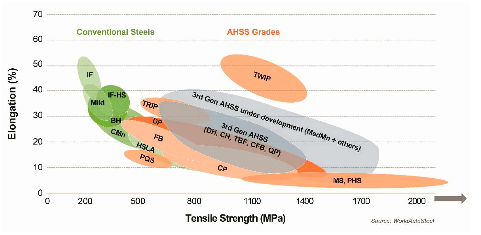
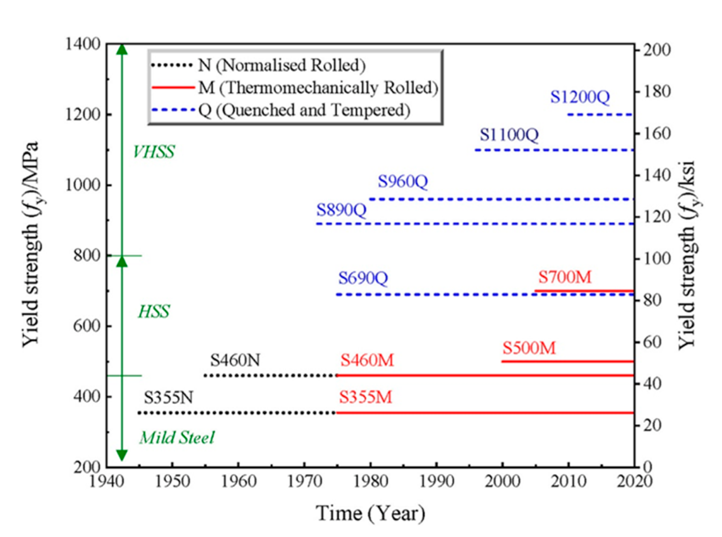
1.1. Historical Development of AHSS

The AHSS grades use a combination of strengthening mechanisms based on the requirements of strength and ductility. From a historical perspective, AHSS can be categorized into the first-generation, the second-generation, and the third-generation AHSS [7]. During the development of the first-generation AHSS, metallurgists attempted to manufacture stronger steels with a higher ductility than ordinary high-strength steels (HSS). This type of steel has a multi-phase and complicated microstructure. Still, traditional HSS with ferrite and martensite phases produced higher strength and more enhanced formability than the first-generation AHSS, but they did not sufficiently reduce the weight. Some of the most commonly utilized grades in the first-generation AHSS include dual-phase (DP), transformation-induced plasticity (TRIP), press-hardened (PH), and complex phase (CP) steels. The second-generation AHSS use more alloying elements to stabilize austenite than the first-generation AHSS, resulting in superior strengths and ductility at a much higher cost and production complexity. Twinning-induced plasticity (TWIP) steels, austenitic stainless steels (ASS), and Al-added lightweight steels with induced plasticity (L-IP) are mostly among the second generation of AHSS. Finally, third-generation AHSS aim to develop material qualities halfway between the first and second generations [8]. Thus, the third-generation AHSS were cheaper compared to the second-generation AHSS. Because of the enhanced strength and ductility of third-generation AHSS, it is possible to reduce sheet steel gauge (thickness) in the automotive manufacturing industry, allowing weight reduction, cost savings, and better fuel economy while preserving or enhancing crashworthiness. The third-generation AHSS include medium-manganese steels, quench and partitioning (Q&P) steels, and carbide-free bainitic (CFB) steels. Quenching and partitioning are the most prevalent production methods for the third-generation AHSS. According to the world auto steel reports, the third-generation AHSS (DP, TRIP, CP, MS, and PHS) expand on the previously established first-generation AHSS (DP, TRIP, CP, MS, and PHS) and the second-generation AHSS (TWIP) [9].
Furthermore, the third-generation AHSS are multi-phase steels developed to improve formability in tensile, shear, and bending tests. Modern automobiles usually contain components with highly complicated shapes and profiles. Various successive forming techniques, such as tensile testing in different directions of samples with varied notch geometries, were required to validate such AHSS parts [10,11]. For example, to improve the formability in automotive applications, TRIP and TWIP steels are being used as excellent choices for weight reduction and increased safety performance, and they exhibit exceptional ductility–strength combinations, as shown in Figure 1. TRIP steel’s high strength is due to its steel chemistry, which includes improved alloying elements and special heat treatment to increase ductility and strength [12].
Figure 1 shows the elongation versus tensile strength diagram of the AHSS grades, and it is commonly described as a banana diagram because the diagram almost resembles the shape of a banana. This exactly reveals the position of the conventional steel grades and the various AHSS. It is also called a global formability diagram (GFD). Here, the steel’s elongation is plotted on the vertical axis, and the strength of the steel is plotted on the horizontal axis. Generally, as elongation decreases, the strength of the steel increases. With the advancement of modern steel choices and additional grades filling the top right section, the elongation versus tensile strength is no longer in the shape of a banana. It is perhaps more correct to call this a football diagram as it resembles an American or rugby football. The steel global formability diagram is the official name for the elongation versus tensile strength plot. This method, too, has its limitations. Ductility can be measured in various ways; elongation is one of them. Other ductility criteria, such as hole expansion and bendability, are becoming increasingly significant with the AHSS grades. Experts have recommended a variety of additional techniques. However, a competitive material must have high degrees of formability, joinability, and weldability and various preparations in addition to low weight and good mechanical behavior. The scientific difficulty in steel development is to alter the chemical composition to have easily formable austenite at high temperatures, quenchable steel that is not too alloyed for excellent weldability, and an acceptable cost.
Accordingly, the new steel grades have always been encouraged to achieve a broad range of properties. An adequate alloy design combined with a toughening technique (hardening and tempering) or a thermomechanical process can increase yield strength (YS) along with the ductility and elongation properties. Many efforts have been made to use modern manufacturing technology in the production of AHSS. The most common structural steel variants are normalized, quenched, and tempered (QT) and use the thermomechanically controlled process (TMCP). Over the past few decades, rolled steel products have enabled the rapid introduction of higher grades, aided by the QT and TMCP processes. Figure 2 depicts the historical development of the steel grades available in Europe for the rolled products incorporated in the EN 10149-2 [13]. Only up to S460N can be normalized to meet the moderate strength and toughness requirements, where 460 represents the YS of the steel grade.
However, there is a constant need for new technological procedures to manufacture better strength steels, which has led to the S460MC, S500MC, S700MC, and S900MC steel grades. However, as stated in various standards, the specific mechanical property requirements may vary, and actual steel products typically exceed these minimum values for various steel producers. Because many steel grades are produced by several steel manufacturers with various brand names, it is often difficult to understand the difference between the grade name and the brand name. For example, S700MC steel with the micro-addition of grain refiners and precipitate is popularly known in European countries by the brand name DOMEX 700 and in the Asia-Pacific region by the brand name JFE-HITEN690S. This steel is manufactured using a thermomechanically controlled rolling (TMCR) process with heating and cooling cycles to obtain superior strength and toughness. Haupt et al. [14] reported that DOMEX 700 steel has a minimum YS of 700 MPa and ultimate tensile strength (UTS) of 750 MPa. Because of its excellent mechanical properties, DOMEX 700 is primarily used to fabricate cranes for the heavy construction industry. Mician et al. [15] reported that the combination of qualities found in TMCP steels, including superior strength, enhanced toughness, and weldability, makes them a potential candidate for various applications, such as heavy vehicles crane booms, earthmovers, etc. Similarly, the S960MC steel grade meets these requirements. This is developed for the load-bearing sections of heavy machinery. The process of grain refinement strengthening is particularly essential as it is the only strengthening mechanism that does not have a detrimental influence on toughness as the strength increases. The steel is rolled with properly controlled deformation and temperature, resulting in a refined microstructure at the end of the process, combined with the precipitation of dispersive precipitates. On the other hand, the mechanical properties might vary depending on the chemistry and processing conditions. Hence, TMCP steels can have strengths ranging from 350 MPa to 1100 MPa [16].
Compared to QT steels, the optimal mechanical properties in TMCP steels are attained through an exceptionally fine-grained microstructure, combined with superior control over the rolling steps at a certain temperature. Grain refinement provides the ultimate strength required to make the S460MC, S500MC, S700MC, and S900MC steel grades. Even though TMCP steels have a lower carbon and alloy content, thinner plates are easier to obtain than thicker plates with higher strengths, limiting their production and application. As a result, the quenched and tempered technique has become the industry standard for very high-strength structural steels. Two temperature-based factors, Ac1 and Ac3 (where Ac1 and Ac3 are the temperatures at the beginning and the completion of austenite formation on heating), used to describe the upper and lower equilibrium temperatures over ferrite and austenite, can be related to the heat-treatment supply conditions of QT and TMCP steels. Except for TMCP steels, which are swiftly quenched below Ac3, the hot-rolling and quenching procedures are carried out above Ac3, while the tempering process is below Ac1. As shown in Figure 3, a high YS is achieved by martensite transformation from austenite during quenching, which has higher strength but is more brittle, and then the tempering of the TMCP and quenched steels to produce a steel grade with the required toughness and ductility for structural applications.
This paper comprehensively discusses the weldability studies on AHSS. The effects of alloy designs on the HAZ softening, the microstructure evolution, and the mechanical properties of the weld joints and filler wire chemistry are discussed.

1.2. Welding of AHSS

Fusion welding is considered to be the popular and prevalent joining technique of various steel grades. Higher demands for welding technology are already being exerted on the automotive and other industrial markets as the economy progresses. Modifying the welding parameters to meet specific requirements and needs is crucial in improving the welding quality of various metals. These steel grades are usually welded together with a comparable or a different steel grade configuration, using fusion welding techniques, most often gas metal arc welding (GMAW) or laser welding. The refined microstructure is produced using controlled rolling and cooling changes during fusion welding; hence, it deteriorates the properties of the weld joint. As a result, the welding procedure plays a paramount role in steel design for controlling the weld joint integrity, the weld microstructure, and the weld joint quality of HSS and AHSS.
For any AHSS, one major requirement for automobile manufacturers is good weldability in homogeneous and heterogeneous configurations. The properties in the fusion zone (FZ) are also a major concern. Because FZ is subjected to frequent heating and cooling, its microstructure is substantially martensitic, with hardness values of 1.5–2 times that of the base metal (BM) [17,18,19,20]. Due to the weld thermal cycles, the final welded joint consists of phase constituents with an appropriate mix of soft and hard phases. As the BM region close to the FZ is fully austenitized during welding, the region closest to the FZ is referred to as “supercritical.” Due to the rapid cooling immediately after welding, austenite completely transforms into martensite. The next region, located further away from the weld, is called “intercritical” because its lower temperatures cause the partial austenitization of the material, resulting in a mixed microstructure of areas not dissolved from the BM (ferrite and martensite) and some martensite generated by the welding. The weld heat input (HI) directly controls the weld thermal cycles; for practical reasons, the ratio of welding power (current and voltage or laser power) to welding speed (WS) is referred to as HI. This method considers a moving heat source along the plate surface, with no losses due to convection or thermal radiation at the external surfaces [21].
The arc welding techniques were introduced in the early 1960s to prevent the potential issues of conventional arc welding techniques. These methods include pulsed GMAW (P-GMAW), pulsed gas tungsten arc welding (P-GTAW), and pulsed plasma arc welding (P-PAW), with pulse frequencies ranging from a few hundred Hz to several thousand Hz [22,23]. The base current keeps the arc burning and the wire melting to generate a droplet. The peak current ensures that a droplet is generated and removed from the electrode [24]. Pal et al. [25] reported that the selection of pulse parameters depends on various factors, such as the type of filler wire and base material, their thermal behavior, phase transformation, and the solidification of the molten weld pool, which affect the various weld quality features, such as the arc stability, bead geometry, weld microstructure, and weld mechanical properties, respectively. The weld joint’s tensile properties are principally determined by the shape of the weld bead and the microstructure of the weld, both of which are impacted by the P-GMAW process parameters. The weld porosity content and residual stress generation due to the weld bead shape greatly influence the fatigue properties. Weld penetration has a significant impact on strength and service life. The weld dilution determines the degree of base metal fusion, which must be sufficient to preserve the weld quality. To improve the final weld quality, the HAZ area must be lowered. The variance in hardness at the WZ/HAZ junction is highly linked with the joint strength.
In summary, the advanced features of arc welding can provide superior weld joint properties compared to those of the conventional welding methods. P-GMAW possesses advantages such as improved arc stability, better weld depth-to-width ratio, high hot-cracking susceptibility, refined grain size, lesser porosity, and a smaller heat-affected zone (HAZ) width [22,26,27,28,29]. In the case of laser welding, a limited portion of the material is heated, melted, and resolidified locally during laser welding. The components are fused after they have been cooled [30]. Table 1 summarizes the various types of AHSS joining methods using different fusion welding processes and their HAZ behavior, mechanical properties, microstructural features, and probable failure mechanisms.
To emphasize the importance of the welding processes, welding HI affects the softening phenomenon and every aspect of the welding process, such as the geometry of the FZ and HAZ. As the welding power increases and the WS lowers, the HI increases. Hence, the process parameters should be selected wisely to obtain a satisfactory weld. Due to high WS or insufficient power, a low HI might lack penetration in the welded joint [31]. However, high HI produces larger weld beads, promoting HAZ softening and reducing grain refinement [32]. Both of these effects are deleterious to the welded joint’s mechanical properties. Because of the increased fraction of hard phases, such as martensite and bainite, the weld hardness tends to be higher than the BM hardness. As a result, if the welding process does not cause HAZ softening, the weld joint will have mechanical properties that are better than or similar to those of the BM.
Table 1. Weld joint mechanical properties and microstructural changes during AHSS welding.
Type of SteelWelding ProcessGradeObservations Reported
Microalloyed steelsGMAWS700MC,
S960QC
[33]
  • HI of 15 kJ/cm produced more carbides in austenite grain. This HI increased the HAZ softening area.
  • The HAZ softening observed due to the heat input and softening width is proportional to the HI.
  • The overmatched filler wires showed improved transverse tensile test results as no failures were observed within the weld zone.
  • Lower welding HI led to high hardness in the weldment.
  • Optimum microstructures were observed, corresponding to 10 kJ/cm.
  • The optimum microstructure can prevent crack propagation in the weld joint.
Laser weldingMicroalloyed C-Mn Steel [34]
  • The FZ microstructure was lath martensite.
  • Inclusions in the FZ were reported.
  • CGHAZ had lath martensite.
  • Refined microstructure.
  • The fracture location of tensile specimens was BM.
  • Impact toughness was higher.
DP SteelsGMAWDP600 [35]
  • GMAW’ ed joints predominantly contained Widmanstatten ferrite microstructure and residual martensite.
  • The weld hardness was 220 HV, which was lower due to the high dilution.
  • Similar UTS for all weld joints.
  • GMAW resulted in lower ductility/toughness.
DP800 [36]
  • HAZ softening.
  • Specimen failed in SC-HAZ due to martensite tempering.
  • Weld metal hardness depended predominantly on dilution and weld joint configuration.
  • The highest hardness was in the weldment.
  • Joint efficiency of 96%.
  • Maximum UTS of 768 MPa.
Laser weldingDP600 [35]
  • Laser welds predominantly contained martensite, and it possessed a hardness of 370 HV.
  • Hybrid welds had mixed microstructures consisting of martensite, bainite, and ferrite, and they possessed a medium hardness of 350 HV.
  • Recommended laser welding as the best for joining DP600 sheets.
HSLA SteelsGMAWTi-Nb Microalloyed steel 800 MPa [36]
  • HAZ softening.
  • Weldment hardness was higher than HAZ hardness.
  • HAZ width was directly related to HI.
  • Weld metal hardness depended predominantly on dilution and weld joint configuration.
  • Specimen failed in the HAZ.
  • Joint efficiency of 86%.
  • Maximum UTS of 685 MPa.
  • The reason for failure was identified as hard TiN particles.
  • HI in P-GMAW was 17% less compared to GMAW.
  • Pulsing refined the microstructure.
GTAWXPF800
[37]
  • Sufficient weld penetration and strength corresponding to an HI of 0.51 kJ/mm–0.85 kJ/mm.
  • 0.4–0.49 kJ/mm HI yielded poor weld penetration and strength.
  • 0.92 kJ/mm yielded poor weld strength and improper weld profile.
  • Highest UTS (777 MPa) occurred in weld with 0.62 kJ/mm HI.
  • Hardness was lowest on the weld due to the highest HI.
  • FZ microstructures consisted of acicular ferrite (AF) and bainite.
Laser weldingNb-Ti Microalloyed C-Mn Steel
[38]
  • Lath martensite was observed in FZ and CGHAZ.
  • BM contained ferrite, degenerated pearlite, and carbides.
  • Impact toughness improved.
  • FZ had superior toughness.
  • HAZ toughness was 91% BM toughness.
  • Laser welding caused the dissolution of original precipitates.
  • Higher elastic modulus in FZ.
  • CGHAZ had a higher elastic modulus than BM.
In summary, the recent development of AHSS demonstrates that advanced research is still progressing rapidly. For superior weldability, global steel producers optimize steel chemistry to keep the carbon content as low as possible, usually between 0.1 wt.% and 0.2 wt.%. Manganese (0.7 wt.%) and silicon (0.7 wt.%) are the other important alloying elements (0.1 wt.% to 0.3 wt.%). These steels undergo different conditions during manufacturing, causing the properties of the BM to vary. Steel users and welding engineers are unlikely to be aware of the different chemistries and resulting variations in weldability among steels produced by different manufacturers. A particular focus is placed on the chemical composition of AHSS to achieve an optimum welding condition to obtain a sound weld structure. Some difficulties, such as HAZ hardening and softening and a reduction in HAZ toughness, cannot be adequately predicted by the commonly used carbon equivalent or other conventional approaches when welding steels of the same strength level. Some standards, specifications, and recommendations have been established for the welding of AHSS. However, these steels behave differently based on various physical (thickness), chemical (alloy design), and thermomechanical (heat treatment and rolling conditions) factors. Moreover, it is important to study the process conditions, including material pre-strain, cooling rate filler wire selection, dilution of alloying elements, and post-heat treatment. Considering the abovementioned factors, this paper has been clearly articulated into various sections and subsections. The weldability challenges in AHSS due to steel processing conditions and the effect of alloying elements are discussed in Section 2. The AHSS behavior due to fusion welding is elucidated in Section 3, which clearly demonstrates the effect of the welding process parameters, filler wire selections, and HAZ behavior for the GMAW and laser processes. The softening mechanism for different AHSS steels, such as DP, TRIP, and HSLA steels, is discussed in Section 4. The mechanical behavior and weld failure mechanisms under different static and cyclic load conditions are discussed in Section 5. Finally, the advantages, disadvantages, and future developments and recommendations for the manufacturing of AHSS to improve weldability for automotive applications are explained in Section 6.

2. Weldability Challenges in AHSS

Microalloyed steel is being used in the automotive industry, pipelines, and the mechanical industry, among other applications [34]. The microalloying of standard C-Mn steel with (Nb, V, and Ti) and the performance of the controlled rolling and cooling can produce different microstructures, such as ferrite, low-carbon bainite, and AF [39]. The ferrite matrix contains a significant amount of carbides with sizes in the nanometer range that increase the steel strength. Hence, it is important to understand the AHSS processing conditions and effects on the microalloying elements when exposed to different thermal cycles during various types of fusion welding processes.

2.1. Weldability Challenges Due to Steel Processing Conditions

The weld thermal cycles have different influences on both the TMCP and the QT steels. A complete understanding of the HAZ behavior is required, as is how the resultant joint properties change due to any fusion welding process. The manufacturing method (QT or TMCP), HI and pre/post-heat treatment, steel chemistry, and filler metal are all discussed frequently. The TMCP and the QT steel welds are susceptible to HAZ softening, although QT steels have a substantially larger softening zone than TMCP steels [40]. The rejection of carbon from supersaturated martensite occurs in the initial tempered microstructure, followed by carbide coarsening, spheroidization, and grain recrystallization. All carbide reactions can occur in a QT steel if it is tempered at an elevated temperature for some time, just as they do in a martensite/bainite mixture. Similarly, HAZ softening is frequent in armour steels and several AHSS grades [41]. When steel has a weld thermal cycle with a peak temperature greater than Ac1, partial austenitization occurs, and the austenite decomposes further into a soft-phase microstructure, such as ferrite or bainite. This also prompts the softening of the HAZ. The hardness loss for a QT weld is evidently only due to the phase transformation reaction to a modest extent and is largely dependent on the tempering process. Similarly, phase change provides a soft microstructure with a coarser grain size in microalloyed TMCP welds, resulting in significant softening. However, when exposed to temperatures below Ac1, TMCP steel exhibits increased hardness rather than tempering softening, owing to a precipitation hardening effect. Steel chemistry must be linked to a thorough understanding of metallurgical behavior. The inclusion of carbide-producing elements (e.g., Cr, Cu, Mo, B, Nb, V, or Ti), which can give precipitation hardening and increase hardenability, can increase the resistance to softening. A plain carbon steel without these alloying components might soften significantly after high-temperature tempering, owing to the quick coarsening of cementite. To minimize excessive softening, pipeline steels were commonly alloyed with B, Ti, Nb, and V elements to improve the hardenability and tempering resistance.
Metallurgical features, primarily phase change and precipitation effects, should be considered when interpreting the softening mechanisms. Two softening reactions are commonly characterized during the welding process based on peak temperature: tempering softening below the Ac1 temperature and transformation softening above the Ac1 temperature, which corresponds to the subcritical and intercritical (Ac1–Ac3) zone and part of the FGHAZ.
Zhang et al. [42] explored the influence of laser welding parameters on nanoprecipitation-strengthened steels. They reported that the hardness is influenced primarily by the microstructure and grain size. The microhardness of the martensitic is higher than bainite, which is higher than pearlite. The lowest microhardness is for ferrite. As the martensite-austenite (M/A) constituent develops during bainite transformation, the carbon-rich, untransformed areas will partially turn into martensite at low temperatures. The formation of M/A constituents leads to degradation in the toughness of the HAZ. Scholars have revealed that the M/A constituent contains two forms of martensite: lath martensite and plate martensite. Lath martensite has a higher martensite transformation start temperature (Ms) and is observed in low-carbon and low-alloy grades. It has an extensive dislocation substructure. Plate martensite is observed in high-carbon and high-alloy grades. It has a twin-intensive substructure [43].
Forouzan et al. [44] studied the brittle fracture behavior of ultra-high-strength, low-carbon steel welds after a quenching and partitioning (Q&P) process. This study performed laser welding on ‘DOMEX 960’ steel. This steel was thermomechanically treated (TMP) and possessed a YS of 960 MPa and an elongation of 8%. An induction heater was positioned above the welded specimens following the laser welding, and the samples were exposed to post-heat treatment. Thermocouples situated at 1.5 mm from the FZ were used to monitor the temperature during the welding and Q&P process. Three partitioning temperatures (PT) of 440 °C (20 °C above the martensite start temperature), 540 °C (halfway between the martensite start and the bainite start temperatures), and 640 °C (bainitic start temperature) and three partitioning times were investigated for the same quenching temperature (QT) of 355 °C (about equivalent to the 60% initial martensite). This study reported that, in addition to the very large precipitates formed during casting, other particles could nucleate, grow, or coarsen during the welding and Q&P treatment. As shown in Figure 4, many particles, such as nitrides and carbides, can be seen in the HAZ. The authors observed Ti (C, N) particles nucleated and coarsened in the HAZ and the growth of nucleated carbides at the grain boundary [44].
In this regard, the welded joints of HSS and AHSS generally have lower mechanical properties than the parent materials because the heat generated during welding modifies the original microstructures in the FZ and the HAZ significantly. Bayock et al. [45] studied the effect of heat input on the microstructure and mechanical properties of dissimilar S700MC/S960QC high-strength steels (HSS), using the GMAW process at three different heat-input values, i.e., 15 kJ/cm, 7 kJ/cm, and 10 kJ/cm. With a cooling rate of 10 °C/s (15 kJ/cm), dissimilar welded samples (S700MC/S960QC) showed a lower-than-average hardness (210 HV) in the HAZ of S700MC than that of the S960QC. Compared to the base material’s value, its hardness was 18% lower. The best microstructure formation was achieved with a heat input of 10 kJ/cm, which resulted in the formation of bainite (B, 60% volume fraction), ferrite (F, 25% volume fraction), and retained austenite (RA, 10%) in the final microstructure of the S700MC. In the S960QC, the final microstructure consisted of bainite (B, 55% volume fraction), martensite (M, 45% volume fraction), and RA (10% volume fraction) in the final microstructure. These findings revealed that forming a higher carbide content at a slower cooling rate decreased both the hardness and the strength. Considering AHSS with different microalloy elements, varied weldability can result from small differences in the microalloy and the processing conditions. Hence, to understand the weldability of AHSS, attention should be given to the compositional factors, in particular the carbon equivalent of the steels. To provide useful guidelines for AHSS weldments, in order to use their benefits in service, the effect of modern welding processes, which could accurately control the amount of heat input to minimize the volume of the HAZ in the AHSS, is also essential. As a result, new AHSS are being developed to improve the ultimate performance of automobile body parts and limit the negative impacts of welding procedures on the mechanical qualities of the weld joints, particularly the strength and toughness.

2.2. Weldability Challenges Due to Alloying Elements

In the case of AHSS, weldability is an important feature to consider for better mechanical properties. According to the Graville diagram, the carbon concentration is reduced to increase weldability; however, it reduces the strength. It is recognized that solid solution strengthening from carbon is the most cost-efficient and effective method of strengthening [46,47]. Although the ultra-low-carbon bainite steel and the copper-bearing age-strengthening of steel improve weldability by lowering the carbon content, the addition of many costly alloying elements, such as Ni, Cr, Mo, and Cu, raises production costs, limiting their use. Another significant breakthrough that coincided with the creation of HSS is the highly specialized alloy design, which necessitates the appropriate heat-treatment procedures. Steel alloys with highly precise qualities have been developed to satisfy specific applications or material properties. The formulated steel must meet all of the standards listed in the applicable standard. Apart from the typical alloying elements, HSS necessitates the employment of the microalloying concept with Nb, Ti, and V.
Thermodynamic and kinetic modelling have proven to be useful tools in developing new alloy designs. Using this modeling technique, the design of various phases and the carbide and nitride proportions in the alloy can be examined. The results of the modeling can be confirmed later by experimental investigation. The phenomenon of huge amounts of the alloying elements being picked up by the weld metal from the BM due to the high dilution effect while employing current welding methods was given special attention. The behavior of austenite grain development in the HAZ and how it influences later phase transformation and toughness qualities was also of great interest [44]. Due to the potentially negative consequences that have been considered in the literature, the involvement of microalloying elements in solid solution or precipitate and their influence on HAZ toughness are of particular interest in this phase transformation process. Under various welding parameters, the effects of the alloying elements on the microstructural changes and transverse tensile, elongation, ductility, and toughness properties are considered.
Jiang et al. [48] studied the weldability of low-carbon steels microalloyed with Nb, Ti, and V. Microalloying greatly improves the low-alloy steel’s strength and is a strong carbide producer. The microstructure influences the YS of medium manganese steel more than the second-phase precipitation. Yang et al. [49] explored the effect of intercritical annealing on cold-rolled Mn steels and found that, especially for alloys with multiphase microstructure, the YS usually reduces as the soft-phase content increases, resulting in a decrease in the yield ratio. It is extremely challenging to analyze the mechanical property changes in multiphase microstructures. On the one hand, Nb, Ti, and V precipitate with the C, improving the strength greatly, while the carbon in tempered martensite drops, reducing the tempered martensite’s strength.
Korkmaz et al. [37] studied the mechanical properties of XPF steels, which have the same high strength as AHSS but have better stretch frangibility and overall strength elongation. XPF has a single-phase ferritic structure, lacking cementite (Fe3C) in its microstructure. Microalloying elements such as Nb, Ti, Mo, and V are responsible for the exceptional strength of XPF steels. Their effects on strength have been studied. To achieve a single-phase ferrite microstructure and maximize the precipitation strengthening, all of the carbon must be utilized to create V, NbV, and NbVMo carbide/carbo-nitride precipitates [50]. The pinning action of XPF800 steel limits grain development by precipitating carbides at the grain boundaries. Dong et al. [51] discovered that the breakdown of carbides caused by high HI did not limit grain growth, resulting in a coarse-grain microstructure. The importance of Nb derives from the fact that it considerably increases the strength of XPF steel. Nb is frequently added to low-carbon steels because it prevents excessive grain development by generating NbC precipitates at the grain boundaries. The hardness can be increased by forming Nb oxide during welding. Nb also aids in transforming non-recrystallized austenite to ferrite [2]. However, Nb influences the toughness of the HAZ, depending on the HI during welding. With precipitation through Nb (C, N), the Nb negatively influences the fracture toughness of coarse-grained HAZ, especially at high HI [52]. The precipitation strengthening and grain refinement are significantly affected by V [50]. V also stimulates the nucleation of AF intergranularly [53]. Mn inhibits the growth of fine carbides by lowering the austenite ferrite transition temperature (Ac3). The addition of a little quantity of molybdenum slows the growth of pearlite and the larger cementite on the grain borders. Furthermore, adding more than 0.09 percent titanium to these steels enhances the YS and UTS [54]. The strength is indirectly improved by including microalloying elements, due to the ferrite grain refinement [55].
The fine-grained microstructure generated by the TMCP method also ensures that S960MC steels have high strength and good formability. The Nb, Ti, and V elements play a predominant role because they generate dispersive precipitates which provide precipitation strengthening [15,16,56,57]. The precipitate strengthening supplied by Nb strengthens steel using carbonitrides particles. Rolling in the recrystallization region, the precipitate strengthening and the fine grain strengthening induced by the V carbonitride precipitates are ways that vanadium improves grain size [58,59]. Hence, none of the heat-treatment procedures can replace the acquired microstructure. The functioning mechanisms of these elements differ, as do their usage ranges. As a result, when steel is subjected to excessive thermal loading, non-reversible microstructural changes occur in the HAZ. As a result of the welding process, changes in the BM occur, which may have an unfavourable effect on the mechanical characteristics of the welded joints. In particular, hydrogen-induced cracking (HIC) and softening may occur [60,61,62,63]. Because modern TMCP steels are more resistant to HIC, the welding processes are focused on preventing the creation of a soft zone in the HAZ [62].

3. AHSS Behavior Due to Fusion Welding

Fusion welding is one of the essential processes for assembling automobile body parts made of different HSS. The load-bearing capability of these components is mostly determined by the quality of the weldments, which includes defect-free welds with the appropriate microstructure and mechanical properties. Welding AHSS is frequently required to realize the full potential of these steels and to provide designers with more options. Numerous investigations by various authors [14,15,34,36,37,39,44,64,65,66] have been conducted into welding AHSS, particularly on the use of gas GMAW and laser welding. The weldability of these steels was examined under various situations utilizing various welding methods, including laser welding, ultra-narrow gap laser welding, GTAW, controlled mode of metal transfer (CMT) during GMAW, and hybrid welding.

3.1. Effect of Welding Process Parameters

During the fusion welding process, the HI, which influences the cooling rate of the HAZ, will subsequently alter the microstructural and mechanical properties. Hence, the HI, the cooling rate, and the welding process parameters play an important role in deciding the final properties of the welded joint and minimizing the property variations in the AHSS. Changes in the HAZ properties become more noticeable when the peak temperature increases and the cooling rate decreases. This is most evident in a widening of the soft zone and, as a result, a reduction in strength. Bayock et al. [67] studied, numerically and experimentally, the effect of welding heat-input parameters on the microstructure and HAZ hardness of QT and TMCP 690-MPa steel. To predict the thermal fields during welding, numerical analysis and experimental comparisons were used, using three heat-input levels (10, 14, and 17 kJ/cm). At a distance of 7 mm from the weld center, the maximum temperature measured in the QT steel and TMCP steel was around 1300 °C and 1200 °C for a heat input of 10 kJ/cm; 1400 °C and 1300 °C for a heat input of 14 kJ/cm; and 1600 °C and 1450 °C for a heat input of 17 kJ/cm. At a 10 kJ/cm heat input, the reported t8/5 cooling times were 14.5 s through the numerical analysis and 18.84 s through the experiments. The QT steel CGHAZ hardness was increased to 317 HV due to the bainite and lath martensite structures with grain growth, while TMCP steel CGHAZ was decreased to 240 HV due to the primary recrystallization of the microstructure and the formation of more equilibrium products of austenite decomposition. Moreover, the welding process is an important consideration in steel design, particularly when it comes to controlling the microstructure and properties of the welded HSS and AHSS joints. For example, when compared to traditional welding methods, laser beam welding (LBW) and the CMT GMAW process have the advantage of a narrowing HAZ. Lee et al. [68] investigated the weld performance of 780 MPa-grade DP steels in laser welded, GMAW, and TIG welded joints and discovered that the width of the welded joints increased with the welding heat input (GMAW > TIG > LBW), and the width of the WS and HAZ increased with the increased cooling rate (LBW > TIG > GMAW). In recent years, CMT has been one of the most significant improvements to the GMAW process, with good effects on process stability and HI control on the BM [69]. Strict electrical controls, such as current-voltage waveforms, with changes in the polarities and electromechanical control of the droplet detachments, are used in these techniques [70,71]. As a result, the auto industry has been working to improve the quality of joining parts by overcoming the limitations of the conventional GMAW process in recent years, leading to the development of pulsed arc technologies for the better joining of AHSS. For most applications, the P-GMAW is widely used, in which the metal transfer is controlled by current pulses between the low and peak levels, with the mean current of the process dropping below the spray transfer threshold (transition current) [24]. Applications with mean currents above the transition current are common, notably in the latest versions of GMAW, which benefit from the pulse mode’s arc stability [72]. The key advantages of the P-GMAW method include a large reduction in heat input compared to the spray transfer and an improvement in the rate of weld deposition, which allows for an effective pulse and base parameter selection [66,72,73,74].
The amount of HI during welding is critical for obtaining superior mechanical properties and microstructure [51,69,75]. Different cooling rates result from changes in the HI. The HI and cooling rates are inversely related. Increasing the HI decreases the cooling rate, causing the sample to tolerate a longer duration at high temperatures, resulting in grain development and boundary displacement [76,77]. Depending on the cooling rates, many ferritic microstructures are found while welding low-carbon steels [50]. In HSLA steels, high HI increases the HAZ grain size. The strength and toughness of the steels are strongly influenced by the weld microstructure, particularly the AF formed during the welding process [78,79]. However, grain coarsening and martensite formation lower the impact toughness in microalloyed steels. The acicular structure improves the hardness values, but the martensite structure is formed due to the rapid cooling rates [80].

3.2. Effect of Filler Wires Addition

Matching welding filler wire is essential for the manufacturing of any structures. HSS with a UTS above 800 MPa is predominantly employed for lightweight structures and heavily loaded components. However, a filler material is required for the deposition of thick sections. Although undermatching welding consumables are sufficient for particular welding procedures and situations, new filler wires with a toughness exceeding 47 J at −20 °C and high strength are needed [65,81,82,83]. Because of the temperature difference, high-strength weld metals exhibit a columnar prior austenite grain (PAG) structure in the as-welded condition [84,85,86]. The width of the PAG columns is determined by the solidification route and the number of inclusions [85,86]. The quantity of the AF in the HSS weld metal is directly related to the PAG column width. The AF, advantageous for toughness, is aided by large PAGs [87,88]. On the other hand, low PAGs are expected to promote high toughness in martensitic steels. The PAGs have a linear relationship with the block size [89,90,91]. As a result, small PAGs will result in tiny block sizes, enhancing the material’s toughness.
Haslberger et al. [92] attempted to study the microstructure and mechanical properties of HSS welding consumables by altering the alloying contents of C, Mn, Si, and V. All the alloys had an oxygen concentration between 400 parts per million and 500 parts per million. The amounts of C, Mn, and Si were changed in the high-strength welding wires, with a minimum YS of 960 MPa, to evaluate their impact on the martensitic microstructure. This study used four wires with different alloying element variations, such as high Mn and Si with additional carbon content to low Mn and Si with V addition. The authors reported improved mechanical properties with low-carbon wire (with a carbon content of 0.08 wt.%) compared to high-carbon wire (with a carbon content of 0.12 wt.%). Although the UTS was reduced, the YS and impact properties were improved. A refined microstructure with a chaotic arrangement of martensitic blocks was reported for the wire with a high carbon content. Compared to the wires with high Mn and Si, those with lower Mn and Si had a larger effective grain size (4.59 µm) and a greater average misorientation (38.1°). A high number of high-angle boundaries and smaller martensitic blocks indicates a higher probability of crack deviation, which improves toughness, and this was validated in this investigation. This study concluded that at room temperature and –20 °C, a synergistic toughening and strengthening concept was employed to generate an all-weld metal sample with a strength of more than 1100 MPa and an impact toughness of more than 47 J [93,94,95,96].
The chemistry of filler wire and the shielding gas combination significantly impact the weld metal properties [74,97]. These should have a major impact on the weld joint’s mechanical and metallurgical qualities. The shielding gas has a significant impact on the physical characteristics of the electric arc, weld pool, and joint strength [98,99]. The filler metal area is largely AF, a phase found in the melting zone of microalloyed steel. Similar results have been reported in HSLA welding, with AF production in the molten zone [100,101]. Zhang et al. [64] studied the development of novel metal-cored wires for welding ultra-low-carbon bainitic (ULCB) steels. The authors used five metal-cored wires with different chemistries, such as C (0.027 wt.% to 0.038 wt.%), Mn (1.64 wt.% to 1.92 wt.%), Si (0.35 wt.% to 0.52 wt.%), Cr (0.13 wt.% to 0.31 wt.%), Mo (0.32 wt.% to 0.78 wt.%), and Ni (1.01 wt.% to 2.01 wt.%), during welding. They studied the deposited weld metal microstructure, the strengthening, and the toughening mechanism. In this study, the effect of the C content on the toughness [62] could be noticed. The toughness of the ULCB welded metals is expected to be improved by lowering the carbon content. However, it could cause a loss of strength that must be compensated for by adding additional alloying elements. The deposited metals’ tensile strength steadily rises from 627 MPa to greater than 700 MPa as the Mo content increases from 0.32 wt% to 0.62 wt%, along with the other alloying elements, and then to greater than 800 MPa as the Mo content increases to 0.78 wt%. The average Charpy V-notch impact toughness at −40 °C decreases as the strength of the material increases. Among the five wires, the maximum impact hardness was observed when the C content was 0.027 wt.%. The impact toughness of material at the same strength level might vary considerably. At 700 MPa, for example, a wire with C 0.29 wt.% + Mo 0.62 wt.% has an impact toughness of 70 J, which is significantly higher than a wire with C 0.043 wt.% + Mo 0.42 wt.%, which has 48 J. Similarly, at 800 MPa strength levels, the wire with C 0.038 wt.% + Mo 0.78 wt.% has an impact toughness of 58 J, which is much greater than the 31 J of wire with C 0.048 wt% + Mo 0.64 wt%. A wire with a low carbon content of 0.027 wt.% is considered to meet E90C-K3, while the wires with C 0.29 wt% + Mo 0.62 wt.% and C 0.043 wt.% + Mo 0.42 wt.% are considered to meet E110C-K4, and the wires with C 0.038 wt.% + Mo 0.78 wt% and C 0.048 wt.% + Mo 0.64 wt.% are considered to meet E120C-K4.The cold-cracking susceptibility (Pcm) of the weld joints is identified using Equation (1) [102]. The highest cold-cracking susceptibility is observed with the highest amount of alloying elements, which is C 0.038 wt.%, Mn 1.92 wt.%, Si 0.52 wt.%, Cr 0.23 wt.%, Mo 0.78 wt.%, and Ni 2.01 wt.%.
Pcm = 5 C 1 + S i 30 + M n + C u + C r 20 + N i 60 + M o 15 + V 10 + 5 B 1
Equation (1) is a well-known carbon formula; an equivalent is the Ito and Bessyo parameter cracking measurement Pcm formula, which is applicable for high-strength pearlite-reduced steels produced by a thermo-mechanically controlled process [103]. Pcm is generally used for modern steel and is typically used for pipeline manufacture, where the carbon contents are no more than 0.11 wt.%. This study concluded that the deposited metal’s strength and toughness were greatly enhanced by reducing the C concentration and optimizing the Mn, Ni, Mo, and Cr amounts. Ferrite, primarily AF and proeutectoid ferrite, predominate at the lowest strength level (627 MPa). However, bainite, primarily degenerated upper bainite and granular bainite, predominates at the maximum strength level (800 MPa).

4. HAZ Behavior in AHSS Welds

AHSS mechanical characteristics are widely recognized to be substantially influenced by their microstructure. The HAZ close to the weld metal undergoes visible changes in microstructure and quality due to the heat generated during welding. The weld thermal cycle’s rapid heating and subsequent cooling cause significant microstructural changes in HAZ. For example, in the case of low-alloy steel with 800 MPa, the phase change processes can be summarized as follows. During the GMAW process, the heating rate causes the temperature rises in such a way that the austenite grains grow fast in the temperature range of 800 °C–1300 °C. Upon subsequent cooling from 800 °C–300 °C, the austenite decomposes into different ferrite morphologies [16]. Depending upon the cooling rate of the welding process, the HAZ behavior varies for various types of steel in terms of the softening and hardening mechanisms.

4.1. HAZ Behavior Due to GMAW Process

Shi et al. [43] investigated the influence of the weld thermal cycle on the microstructure and fracture toughness of the simulated HAZ of an HSLA steel during GMAW. In this study, the authors adopted a 16 mm-thick steel plate with a YS of 845 MPa, a UTS of 880 MPa, an elongation of 15%, and fracture toughness of 115 J and 9 J at 20 °C and −40 °C, respectively. As with the GMAW process thermal cycles, the samples were heated to 1300 °C during the thermal simulation procedure, followed by a quick hold period of around 2 s and varied cooling intervals between 1300 °C and 800 °C and 800 °C and 500 °C. The variation of the volume fraction of the M/A constituent, with cooling time t8/5,is shown in Table 2.
The authors observed that the volume fraction of the M/A component increases with an increase in cooling time t8/5. A higher volume fraction of the M/A constituent was reported for a cooling time of 100 s. Furthermore, it was also observed that with the increased cooling time, the morphology of the M/A constituent changed from bar to block. Figure 5 represents the typical morphology of the M/A component at various cooling durations.
This study concluded that the size of the prior austenite grains and the volume fraction of the bainitic ferrite and M/A constituents increased as the cooling time increased. On the other hand, the volume fraction of the martensite decreased with the increasing cooling time. Apart from the microstructural changes, the weld thermal cycles also significantly influence the retarding hardness loss during tempering on the different types of AHSS. Majlinger et al. [104] studied dissimilar AHSS sheets of TWIP and TRIP steels joined with thicknesses of 1.4 and 0.9 mm, respectively. At the linear HI range of 500 kJ/m to 650 kJ/m, the GMAW process proved effective. At the examined GMAW parameters, the HAZ of the TWIP steel largely exhibits grain coarsening. Nonetheless, the TRIP steel’s HAZ undergoes various microstructural modifications that are proportional to the distance from the weld bead. TWIP steel has a 240 HV hardness, while TRIP steel has a 250 HV hardness. Figure 6 depicts the usual hardness profile of a TWIP–TRIP welded butt joint. The HAZ on the TWIP steel side is approximately 4 mm wide, according to the hardness profile. The persistent reduction in grain size has a strengthening effect due to an increase in hardness up to 2 mm from the fusion zone’s border. The HAZ on the TRIP side is roughly 6 mm wide, which is larger than the HAZ on the TWIP side, according to the hardness measurements, which agrees with the findings of the microstructural studies. During sheet joining, the TRIP side austenitized in the fusion zone, along with martensite with a maximum hardness of about 490 HV. This study concluded that the HAZ of the TWIP steel (austenitic grains) mainly exhibits grain coarsening at the studied GMAW parameters. Still, the HAZ of the TRIP steel (ferrite grains) exhibits distinct microstructural changes.
Similarly, Afkhami et al. [105] studied the weldability of S700MC and S1100 using the GMAW process. The microstructures, hardness profiles, tensile characteristics, and fracture toughness of the weld joints were used to evaluate the weldability of these materials. Except for some minor tempered martensite, S1100 had no hazardous phases in the HAZ and the BM after welding. The size and distribution of the tempered martensite islands, on the other hand, were not large enough to exhibit any deleterious effects on the welded joints’ static mechanical properties. Although some undesired phases, such as the upper bainite and tempered martensite, were spread among the HAZs of S700MC, they were insufficient to change the mechanical characteristics. The major finding of this research is that the hardness values on the cold-formed side were moderately higher than those on the virgin side, as shown in Figure 7 and Figure 8. This behavior can be explained by the cold-formed material’s greater dislocation density and strain-hardening behavior [106]. Furthermore, because it was the most severely heated zone, the middle portion had the lowest hardness value along its cross-sectional area. The HAZ subzone has a different proportion, morphology, and roughness of bainite and martensite to the rest of the HAZ.

4.2. HAZ Behavior Due to Laser Welding Process

Sun et al. [34] compared laser welding and the GMAW process for 800 MPa microalloyed C-Mn steel welded joints. They reported that by varying the distances from the weld center, the peak temperature, the time at high temperature, and the cooling rate in each HAZ were different, which resulted in variations in the different microstructures within the HAZ. The authors classified HAZ into coarse-grained HAZ (CGHAZ), fine-grained HAZ (FGHAZ), or mixed-grained HAZ (MGHAZ). The hardness distribution for the two welding processes is shown in Figure 9. The welded zone hardness of GMAW was found to be equivalent to that of BM (265–275 HV), with CGHAZ having the highest value of 320 HV. FGHAZ and MGHAZ have a lower hardness than BM. For the LBW welded samples, the hardness of the FZ and HAZ was higher than the BM and GMAW, and the maximum value was found in CGHAZ, exceeding 377 HV. The HAZ width was higher for GMAW than for laser welding.
Figure 10 shows the CGHAZ microstructure details for both welds. The microstructure with the AF and fine-grained ferrite was found in the FZ of GMAW. In contrast, lath martensite was found in the FZ of LBW, where the inclusions were finer and did not act as nucleation sites for the AF. The two welding procedures produced coarse-grained HAZ with lath martensite and granular bainite microstructures. In the CGHAZ of LBW, the initial austenite grain size was 1/3 that of the CGHAZ of GMAW. The microstructures of fine-grained HAZ and mixed-grained HAZ produced by the two welding processes comprised ferrite and M-A components, whereas the microstructure of LBW was much finer.
This study concluded that the hardness of the LBW welded joints was higher than that of the BM, which served as the fracture starting site during tensile loading. Tensile fractures in GMAW welded joints occurred in the weld center. Zhang et al. [42] performed laser welding of hot-rolled nanoscale precipitation-strengthened steels. They reported the effect of laser power on the microstructural changes in the HAZ. Figure 11 illustrates the evolution of the CGHAZ and FGHAZ microstructures due to laser welding. The HAZ near the FZ displayed a high peak temperature (higher than the austenitic coarsening temperature) in the fusion line (FL) and CGHAZ, indicating that the original microstructure is entirely austenized (Figure 11a). Because the cooling rates are so fast (2000–3000 °C/s), the carbon and the alloy elements in the austenite do not have enough time to diffuse throughout the cooling step [107]. The austenitic structure is changed to martensite at low temperatures (Figure 11a). The peak temperature at FGHAZ approaches the grain-refining temperature after cooling, resulting in complete austenitization but no coarsening, as well as a small amount of ferrite and LM (Figure 11b).
This study concluded that the average FZ width reduced as WS increased, whereas the average FZ hardness and HAZ hardness increased. The microstructures of the FZ, the fusion line, and the CGHAZ were all lath martensite, while the original austenite grain boundaries grew in different directions. Ferrite and martensite were found in the FGHAZ, while ferrite, a huge M/A island, and tiny quantities of martensite were found in the MGHAZ. The FZ, HAZ, and BM have microhardness values of 358 HV, 302 HV, and 265 HV, respectively. Hardness is found to have a proportional relationship with the butt joint fracture at the BM and tensile strength of the weld joint. Guo et al. [108] conducted LBW on high-strength S700 steel plates in the flat position (1G) and horizontal position (2G), i.e., the laser beam direction was orthogonal to gravity. This study reported that laser welding in a horizontal position could prevent common welding defects such as undercut and sagging. As demonstrated in Figure 12a, the weld microstructure was bainite in the flat and horizontal positions. In both cases, the microstructure in the HAZ is bainite mixed with martensite, as illustrated in Figure 12b.

4.3. Softening Mechanism in AHSS

Scholars have reported the softening phenomenon in various AHSS. This section discusses the HAZ softening during the welding of DP, TRIP, and HSLA steels.

4.3.1. Softening in DP Steels

DP steels are prone to softening at the sub-critical heat-affected zone (SCHAZ) due to the tempering of the martensite islands, which has been extensively studied by many researchers [18,41,109,110,111,112,113,114]. A composite microstructure consisting of ferrite, martensite, and bainite provides DP steels with significant strength and ductility. However, because martensite is a thermally unstable phase, it will dissolve in the HAZ, causing local microstructure softening, which is considered a prominent softening mechanism in the case of DP steels. In DP steels, HAZ softening is unavoidable and occurs in the SCHAZ when welding temperatures do not exceed the material’s Ac1 temperature. The mechanical properties of this section of the HAZ are characterized by a reduction in yield and ultimate tensile strength, an increase in ductility, and the return of yield-point elongation, as martensite tempering, profoundly modifies the DP microstructure. HAZ softening can cause strain localization and failure in the SCHAZ [115]. Wang et al. [116] studied martensite decomposition and discovered that carbides develop and dissolve rapidly, indicating cementite formation and the growth of carbides. Biro et al. [41] studied softening kinetics in the subcritical heat-affected zone of dual-phase steel welds. This study observed that the heat input required for HAZ softening decreased as the C content of the martensite within the DP structure increased. However, carbide-forming alloying elements such as Cr and Mo increased the resistance to softening. Two DP600 and two DP780 steels with differing chemistries were used to produce bead-on-plate welds. The hardness of the subcritical zone was measured after welding. The minimum HAZ hardness for all the steels was found to decrease as the heat input increased until a minimum value was reached. The heat input was increased further but had no effect on the SCHAZ hardness. Moreover, the martensite decomposition product in the SCHAZ for all welds was cementite. Xia et al. [18] studied the effects of heat input and martensite on HAZ softening in the laser welding of different types of DP steels. The martensite content and heat input were found to be functions of HAZ softening in DP steel. The maximum HAZ softening was proportional to the martensite content, and the heat input was determined when the softening was achieved. The maximum softening for different strength levels of DP steels was the same when the martensite phase softening was isolated from the overall HAZ softening, although the softening kinetics differed.

4.3.2. Softening in TRIP Steels

A few studies on softening at the SCHAZ of TRIP steels using laser or arc welding processes have been reported [117,118]. Zhao et al. [117] suggested that softening was caused by the loss of retained austenite due to a difference in cooling rates and the presence of a substantial fraction of ferrite, but no more evidence was presented. A HAZ softening phenomenon in TRIP steels was also reported by Xia et al. [118] during diode laser welding of TRIP800 steel, but no further investigation results were presented. Guzman et al. [119] examined the effect of the SCHAZ microstructure on the mechanical properties of Si-TRIP steel welds. This study investigated the influence of the fusion zone and SCHAZ microstructure on the tensile and forming behavior of Si-TRIP steel when subjected to different welding processes such as laser and arc welding. The measurable softening (tempering) of arc-welded Si-TRIP steel at the SCHAZ was found to be the result of a combination of metallurgical processes, including the precipitation and coarsening of carbides within the prior islands of martensite, the precipitation of the supersaturated austenite phase, and the partial-recovery of the martensite lath substructure. Sharma et al. [120] studied laser welding of TRIP780 steel with dual-phase and mild steels for use in tailor-welded blanks. This study utilized a laser beam to join 1 mm-thick TRIP780 with 1.5 mm-thick DP980 and 1 mm-thick mild steel. The results showed a slight softening of the HAZ in TRIP, and, on the other hand, a significant softening of the HAZ was noted in the DP980 base metal regions. However, it did not affect the outcome of the tensile tests for the combinations tested. Scholars have reported that only high-strength steels, such as M900 martensitic steel, have shown local softening in the HAZ. This indicates that if DP980 is welded to DP980 using the same technique, the HAZ will be soft, and fracture will be likely during tensile testing. Panda et al. [121] conducted tensile and formability tests on DP980 steels and reported the same. Because microhardness values are related to tensile strengths, the fractures are likely to occur in the HAZ of DP980 or TRIP780 steels or in the TRIP780 base metal. Compared to roughly 150 HV in the base metal, the HAZ in the mild steel region had substantially greater microhardness values of 200 HV or higher. However, the slight HAZ softening in the TRIP–DP combinations was confirmed by tensile testing to be negligible.

4.3.3. Softening in HSLA Steels

Rahman et al. [122] performed microstructural studies of HSLA steels on the phenomenon of HAZ softening. As a result, the mechanical properties of the HAZ may be considerably altered, and a softened zone may develop. Several factors, including the chemical composition, production parameters, and total heat input of the employed welding method, influence the degree and extent of softening in the HAZ. With increasing cooling time to t8/5, the thickness of the soft interlayer expands linearly. Furthermore, regardless of the welding procedure used, increasing the t8/5 causes a greater reduction in the hardness of the HAZ and weld metal. The hardness drop approaches a saturation value with a longer t8/5, which the production process could induce. The softened minimum hardness of the HAZ is a direct function of the carbon equivalent [40,60,123].
Maurer et al. [124] evaluated the factors influencing the strength of an HSLA steel weld joint with softened HAZ. The steel under investigation was a TMCP steel strip (S700MC) with sheet thicknesses of 6 and 10 mm, microalloyed with Ti, Nb, and V. In the delivery state, the microstructure is mostly bainite and ferrite. Grain refining, precipitation hardening, and a small amount of transformation hardening give this steel its strength. Welding experiments were carried out using the GMAW process to assess the impact of several parameters on the static strength, including a soft zone in the HAZ. The soft interlayer relative thickness exhibits a considerable reduction in static tensile strength. The softening of the HAZ (softening ratio) has the second-highest effect on static joint strength, followed by the matching ratio, which is the third most important factor. Korkmaz and Meran [37] studied the microstructural features and mechanical properties of GTAW’ed ferritic XPF800 steel. They also reported the softening in the HAZ of the weld joint. The variation of microhardness in the FZ, HAZ, and BM XPF800 steel weld is shown in Figure 13. The figure demonstrates a significant drop in the hardness of the HAZ compared to BM and FZ. Maximum hardness of 300 HV is reported in the FZ, and the BM possesses 270 HV. Microhardness corresponds to base metal, fusion zone, and HAZ and depends on the corresponding microstructures in these zones. Despite the small grain structure of HAZ, the hardness dropped to 240 HV. During tensile testing, the weld specimens failed in the HAZ, suggesting a reduction in the strength of the HAZ. This study concluded that when HAZ temperatures rise above Ac1, most of the initial microstructure is expected to be converted into fine austenite grains. During subsequent cooling, austenite decomposes into either ferrite or bainite. Both microstructures have a lower strength.
Softening during welding can be classified into transformation softening (if the temperature is above Ac1) and tempering softening (below Ac1), depending on the temperature attained. Several investigations on softening phenomena have identified high HI and a slower cooling rate as the main reason for inferior strength [40,45,61,125]. Changes in the HAZ characteristics become more obvious when the peak temperature increases and the cooling rate decreases. This is most evident in a widening of the soft zone and, as a result, a loss in strength. The drop in strength is not evident due to the constraint effect, and it only happens if the soft zone’s width is excessive. Maurer et al. [124] and Rodrigues et al. [126] have explained the concepts of the constraint effect on welded joints. Several investigations have demonstrated that, despite the presence of the soft zone, the strength of the welds reaches the values of the BM. However, the strength is greatly reduced if the soft zone is too wide.
Mician et al. [15] conducted GMAW on HSLA steel S960MC. The microhardness and microstructural investigations were used to establish the soft zone features. The soft zone width was determined using microhardness measurements. The methodology for calculating the soft zone’s width differs based on the authors’ interests. Some studies treat the whole HAZ as a soft zone [16,62,127]. The fracture always occurred in the intercritical HAZ or sub-critical sections during tensile testing. Hence, it was concluded that the FCHAZ has a partial constraint effect and cannot be considered a soft zone. In the case of all the welds examined, the soft zone was found in the low-temperature HAZ, i.e., sub-critical HAZ. Due to the microstructural properties of the sub-critical HAZ, where the width could not be identified and based on the width of the indicated subzones, softening determination was not feasible. To calculate the width of the soft zone, a technique based on the reduction in hardness compared to the BM was adopted. The soft zone was defined as the area where the hardness was less than 90% of the hardness of the BM. This limit assumes that hardness and strength are related.
Similarly, Wald and Jandera [128] have also proposed a comparable soft zone limit value of this size. Both the HAZs of welded joints had their hardness measures analyzed in the line. The soft zones from the weld side where the fracture occurred along the soft zone width are shown in Figure 14. The 90% hardness of BM is 324 HV, which is shown by the red dot-dashed lines.

4.4. Softening Behavior Due to Thickness

The thickness of the welded material is an unavoidable factor while correlating the soft zone width with weld joint strength. Hence, experimental investigation reporting the softening phenomenon in the weld joint always measures the relative thickness of the soft zone. The thickness of the soft zone is defined as the ratio of the soft zone width to the material thickness. As the welded joint strength increases, the soft zone thickness decreases. The weld can theoretically approach the strength of the underlying material if the soft zone thickness is tiny enough. However, depending on the BM, the methodology for defining the soft zone, and the filler material utilized (overmatching, matching, or undermatching weld metal), the value limit varies. [15,36,40,60,124,129]. Jambor et al. [127] demonstrated the GMAW technique for the welding of S960MC steel under different HI. A significant increase in strength was achieved by decreasing the HI, but it was still below the values of the BM. However, this may not be applicable for the welded joints with higher thicknesses.
Lahtinen et al. [130] and Silva et al. [131] observed and summarized that as the heat transfer from the weld increases and the thickness of the material increases, the ensuing width of the soft zone does not result in a drop in strength. Despite the wider width of the soft zone, thicker welded joints normally have no difficulty in achieving the desired strength. This is because the soft zone width is tiny enough when considering the thickness of the BM. The welding of low-thickness sheets is particularly difficult where the soft zone is too high and the strength of the weld joints is inadequate. This is because the heat transfer from the weld is slower, resulting in a slower cooling rate. The increased width of the soft zone is affected by the lower cooling rate, which results in the welded joint strength dropping significantly in the case of lower-thickness materials. When welding thin sheets, it is crucial not to exceed the maximum HI. This drop in strength is commonly tolerated for specific applications, but it should be acknowledged that the basic material qualities are being used inefficiently.

5. Failure Mechanism of AHSS after Welding

Only a few researchers have looked into the major issue of AHSS grades during welding and reported degradation in the mechanical properties during welding. Denisa et al. [132] compared the fatigue parameters of as-received material to the fatigue life of the GMAW joints of Domex 700 MC. The base material, Domex 700 MC, was tested for fatigue endurance in both as-received and welded conditions using the rotational bending Rotoflex testing instrument. The loading frequency f = 35 Hz and the cycle asymmetry ratio R = −1 were employed as test parameters. The fatigue results show that GMAW joints possess inferior fatigue properties compared to the base material. With an increasing number of cycles, the S-N curves of the welded and non-welded specimens show a decreasing trend. The welded specimens fractured at higher stresses (420 MPa) after 4 × 10⁵ loading cycles, indicating a poorer fatigue life than the base material, which fractured at 540 MPa after 1 × 10⁵ loading cycles. After welding, the fatigue limit (calculated for 1 × 10⁷ cycles) decreased from 422 MPa to 368 MPa for the base material. The grain coarsening in the HAZ region during welding could be the main reason for the decrease in the fatigue life of welded samples. Sharifimehr et al. [133] explored the effect of periodic overloads and underloads on the fatigue behavior of GMAW’ed SPFH780 steel. This steel finds applications in vehicle chassis, and this steel is a fully ferritic steel with fine precipitates. Here, the authors considered single-lap shear and butt arc welds as weld geometries. The stress and strain states at the weld points under overloads and underloads were simulated using finite element calculations, and the results were utilized to explain the experimental findings.
The stress distribution in the direction of the applied load is illustrated in Figure 15. The arrows in this diagram represent the location where the stress is concentrated to the maximum extent. The location of the highest strength concentration in both welds corresponds to the crack initiation location in the specimens during the testing. The fatigue life of the single-lap shear weld joint remained unaltered. Still, the fatigue life of the butt welded joint increased when subjected to periodic overloads compared to constant amplitude loading. The applied load for the single lap shear joint is 15.6 kN, and for the butt weld joint, it is 21.73 kN. The R ratio was 0.1, 0.62, and 0.67.
Similarly, Svoboda and Nadale [134] studied the fatigue life of GMAW’ed and plasma arc welded (PAW) microalloyed steels. The weld joints were microstructurally and mechanically examined. The tensile strength, fatigue, and microhardness of the material were investigated. It was observed that both joints had a softened zone with microhardness varying from 240 HV to 270 HV in the HAZ, compared to the BM 300 HV (martensite tempering). At the hardened zone, a hardness of 500 HV near the FZ was observed; the higher microhardness was due to the creation of new martensite. The reported microhardness in the FZ was 360 HV to 400 HV, which is attributed to the dilution. Both techniques achieved an excellent joint efficiency of 97% in the tensile test, and the fracture location was observed in the softened HAZ. The crack nucleation site for the GMAW’ed specimens was weld toe-propagated through the HAZ and FGHAZ in a direction perpendicular to the tensile stress. Depending on the stress level, the crack nucleates in different zones for PAW’ed joints. The fracture originated from the FZ for high-stress levels; for medium stresses, the crack initiated at the softened zone, and for lower stress levels, the crack nucleated in the CGHAZ [135]. However, the authors reported that the fatigue life of the PAW’ed specimens was 78% higher than the GMAW’ed specimens. This is due to the local stress rise in the toe of the GMAW beads.
Korkmaz and Meran [37] explored the impact of weld HI on XPF800 steel welds. The authors used an HI of 0.4 kJ/mm to 0.92 kJ/mm in their experiments and correlated with the final mechanical properties. The weld geometry profile and the mechanical characteristics were examined. The authors reported that a peak UTS of 777 MPa corresponds to a 0.62 kJ/mm HI. Figure 16 shows the SEM of the tensile fractured surface. Ductile fracture is seen in metals with high impact toughness, and the fracture surface has multiple dimples and tearing edges [136]. The quasi-cleavage fracture occurs in metals with low impact toughness, resulting in river-like patterns on the fracture surface. On the fracture surface of the BM, a quasi-cleavage fracture with river-like patterns was observed. XPF800 steel weld and BM have a ductile fracture, with multiple dimples and rip ridges.
Wegrzyn et al. [137] studied the MAG welding process coupled with micro-jet cooling on S700MC steel. Such joints were reported for the first time and the authors carefully investigated the mechanical properties. The authors summarized that the cooling coupled with welding could produce good quality joints with superior mechanical properties. The micro-jet cooling settings impact the attributes of the S700MC joint. The non-destructive and destructive tests show that employing micro-jet cooling during welding is efficient. The fatigue test results revealed that the MAG process with microjet cooling could be used for safe constructions. Many surface-strengthening methods can be applied to the post-processing methods to enhance the mechanical properties such as the fatigue and corrosion resistance of the weld joints of AHSS [138,139,140,141].

6. Advantages, Disadvantages, and Future Directions of AHSS

The above-mentioned sections summarize several state-of-the-art discussions regarding global trends and challenges in AHSS fusion welding. Moreover, these steels behave differently under steel-processing conditions such as TMCP, QT, and QP and changes in the microalloying elements ratio. It gives an overall understanding of their influence on the weld microstructure and mechanical properties. Many research investigations focused on the HAZ’s behavior and the softening phenomena. The welding parameters and the steel composition significantly impact the softening behavior. Increased HI widens the softening zone and worsens the consequences. A thorough examination of the microstructure reveals that softening is closely correlated to distinct phase compositions and morphologies. Various fusion welding processes were investigated, and the impacts of different filler wires on the FZ were summarized. The mechanical properties, followed by failure mechanism studies, revealed that well-adjusted welding procedures were used to achieve consistent weld quality. The final mechanical properties of weld joints depend on various factors, including alloy design, microalloying element type, and welding parameters. The precise effect of each factor and its interaction during the welding of modern high-strength steels were explored in depth.
The main advantages of the present AHSS lie in the maintaining of the high formability required for manufacturing. In the past few decades, AHSS have been of a new generation of steel grades that provide much higher strength and other advantageous properties in comparison to other materials. Engineers can use AHSS to address low-cost requirements for safety, efficiency, emissions, manufacturability, durability, and quality. The importance of AHSS in the automotive industry is growing all the time, and they will continue to be the primary material for vehicle mass production. One of the most important design issues in vehicle structure design is ensuring that the structure can handle the requisite static and dynamic loads, particularly in the case of a crash. Crash load management relies heavily on proper material selection and vehicle design. For these zones, AHSS grades with high work-hardening, strength, and ductility are used. In the event of a low-to-no-fuel situation, the safety cage, or passenger compartment zone, is designed to maintain its integrity with minimal deformation to safeguard the people and the fuel system.
Along with their many benefits, AHSS have several drawbacks, such as higher wear on the forming dies, flange stretching, increased spring back, weldability, edge cracking, fatigue, and so on [142]. One of the most severe problems with AHSS welding is the microstructural degradation caused by the weld thermal cycle, which causes AHSS welds to be weaker than the base material. In terms of welding, AHSS demands a different strategy to traditional automotive steel. The objective is to generate and develop welding processes that reduce microstructural damage while achieving the best mechanical properties for the welded joints. Another crucial consideration is productivity; in order to improve it, welding speed must be as high as possible.
Beyond the third generation of AHSS, various research projects are underway to develop ultra-strong steels with tensile strengths of more than 2 GPa. A few authors described several techniques, including high dislocation density–induced ductility in deformed and partitioned steels, with a UTS in the range of 2000 to 2200 MPa and uniform elongation of 15–20% [143,144,145,146]. The high-strength-induced multi-delamination technique is a new way to manufacture engineering materials with ultra-high strength and toughness.
The welding of the future generation of AHSS parts may differ from existing steel parts because future AHSS will have increased carbon and alloying elements, making them more susceptible to welding. Rapid heating and cooling during the welding process, as well as the steel chemistry, have a significant impact on the microstructure, mechanical characteristics, and fatigue life of the steel. As a result, the welding parameters must be tightly controlled. GMAW is most commonly used in chassis, where the strength and rigidity of the junction are critical. The method also allows pieces of varied shapes to be joined to structural sections such as pipes and brackets. It is necessary for the weld joint to have a long fatigue life. Apart from GMAW welded autobody parts, customized welded blanks are an essential technical product. Laser welding has grown in popularity over the last two decades because lasers have a high-power density (108 W/cm2) and can thus weld steel at fast speeds to satisfy rigorous productivity requirements. When compared to traditional arc welding methods, it has a lower HAZ. This feature is more suitable for the welding of AHSS. Carbon dioxide lasers are the most popular lasers utilized in sheet metal fabrication, especially for tailor-welded blanks incorporating different future-generation AHSS combinations. Several car manufacturers, on the other hand, use high-power fiber and disc lasers to weld AHSS.
However, the welding techniques developed for one type of AHSS may not be applicable to another. Hence, exploring alternative joining methods is another approach for joining in the future AHSS. Solid-state welding methods and other alternative joining technologies have recently been investigated with the goal of decreasing the microstructure damage of AHSS induced by the welding [147]. Adhesives are used to increase the rigidity of a part by forming a continuous junction. Weld bonding is favoured by some manufacturers due to concerns about the endurance of adhesive joints under various environmental conditions [148]. Future AHSS grades will be able to further reduce vehicle weight while also improving vehicle performance and safety without incurring substantial cost penalties. Increased knowledge of weldability and joining, prediction and control of spring back and fracture, and improved fatigue performance will lead to AHSS being exploited by other industries.

7. Conclusions

This review evaluated the specific concerns that focus on the fusion welding of AHSS with tensile strength levels above 800 MPa. A major part of the study discussed HAZ behavior, including its metallurgical and mechanical properties, focusing on microhardness, strength, and toughness in response to the varied welding conditions. During the welding of AHSS, the weld thermal cycles influence the HAZ, resulting in a softening zone. In most mechanical characterizations, particularly tensile tests, the narrow layer with reduced hardness undergoes intensive deformation, leading to eventual failure in the softened HAZ. Furthermore, it is also important to understand that the increased HI widens the softening zone width and amplifies the negative effects of softening. Two important aspects influence the HAZ softening behaviour: transformation products and tempering resistance. After partial austenitization, phase change products, particularly large-size ferrite and coarse carbide, coalesce and contribute significantly to the softening of the HAZ. When assessing the AHSS weldment integrity, each region of the weld joints, i.e., the FZ, HAZ, and BM, must have appropriate qualities. Between HAZ hardening and softening, the final strength or mechanical properties are a delicate balance to strike. Low toughness and excessive softening are disadvantages that can be mitigated by selecting the right welding parameters. However, identifying matching filler wires for the AHSS with strength levels above 800 MPa is another challenge. In this scenario, the weld metal qualities should be focused on the choice of filler metal and the high dilution of BM when using advanced welding technology. Determining the microstructure evolution in the weld metal requires an understanding of alloy pick up. To summarize, considerable attention must be dedicated to steel alloy design and weldability to obtain homogeneous mechanical properties in AHSS welds with minimal metallurgical alterations.

Author Contributions

Conceptualization, A.K.P.; methodology, A.K.P.; writing—original draft preparation, A.K.P., M.J. and U.B.K.; writing—review and editing, A.K.P., M.J., U.B.K. and P.L.M.; supervision, P.L.M. All authors have read and agreed to the published version of the manuscript.

Funding

This research received no external funding.

Institutional Review Board Statement

Not applicable.

Informed Consent Statement

Not applicable.

Data Availability Statement

Data sharing is not applicable to this article.

Acknowledgments

The authors acknowledge the Tata Steel Limited, Jamshedpur, and the Department of Mechanical Engineering, University of Nevada, Reno, for providing all the research facilities.

Conflicts of Interest

The authors declare no conflict of interest. The funders had no role in the design of the study; in the collection, analyses, or interpretation of data; in the writing of the manuscript, or in the decision to publish the results.

Abbreviations

AHSSAdvanced High-Strength Steel
BMBase Material
HAZHeat-Affected Zone
HSLAHigh-Strength Low-Alloy Steel
HSSHigh-Strength Steel
FGHAZFine-Grain Heat-Affected Zone
CGHAZCoarse-Grain Heat-Affected Zone
AFAcicular Ferrite
FGFFine-Grain Ferrite
GMAWGas Metal Arc Welding
P-GMAWPulsed Metal Arc Welding
CMTCold Metal Transfer
GTAWGas Tungsten Arc Welding
PAWPlasma Arc Welding

References

  1. Shome, M.; Tumuluru, M. (Eds.) Welding and Joining of Advanced High Strength Steels (AHSS); Woodhead Publishing Series in Welding and Other Joining Technologies; Woodhead: Cambridge, UK, 2015; ISBN 978-0-85709-436-0. [Google Scholar]
  2. Kuziak, R.; Kawalla, R.; Waengler, S. Advanced High Strength Steels for Automotive Industry. Arch. Civ. Mech. Eng. 2008, 8, 103–117. [Google Scholar] [CrossRef]
  3. Cheah, L.W. Cars on a Diet: The Material and Energy Impacts of Passenger Vehicle Weight Reduction in the U.S. Ph.D. Thesis, Massachusetts Institute of Technology, Cambridge, MA, USA, 2010. [Google Scholar]
  4. Tolouei, R.; Titheridge, H. Vehicle Mass as a Determinant of Fuel Consumption and Secondary Safety Performance. Transp. Res. Part D Transp. Environ. 2009, 14, 385–399. [Google Scholar] [CrossRef]
  5. Demeri, M.Y. Advanced High-Strength Steels: Science, Technology, and Applications; ASM International: Materials Park, OH, USA, 2013; ISBN 978-1-62708-005-7. [Google Scholar]
  6. Galán, J.; Samek, L.; Verleysen, P.; Verbeken, K.; Houbaert, Y. Advanced High Strength Steels for Automotive Industry. Revmetal 2012, 48, 118–131. [Google Scholar] [CrossRef]
  7. Matlock, D.; Speer, J.; Moor, E.; Gibbs, P. Jestech Recent Developments In Advanced High Strength Sheet Steels For Automotive Applications: An Overview. Available online: https://www.semanticscholar.org/paper/Jestech-Recent-Developments-In-Advanced-High-Sheet-Matlock-Speer/2bfca3c314ae862b5d166e9cf36ed1e184dfdb21 (accessed on 3 March 2022).
  8. Yang, Y.; Sung, J.H.; Wagoner, R.H. Failure Analysis of Advanced High Strength Steels (Ahss) During Draw Bending. In Proceedings of the International Deep Drawing Research Group IDDRG 2009 International Conference, Golden, CO, USA, 1–3 June 2009. [Google Scholar]
  9. WorldAutoSteel AHSS Insights Blog: The New Global Formability Diagram. Available online: https://www.worldautosteel.org/ahss-insights-blog-the-new-global-formability-diagram/ (accessed on 3 March 2022).
  10. Jocham, D.; Gaber, C.; Böttcher, O.; Wiedemann, P.; Volk, W. Experimental Prediction of Sheet Metal Formability of AW-5754 for Non-Linear Strain Paths by Using a Cruciform Specimen and a Blank Holder with Adjustable Draw Beads on a Sheet Metal Testing Machine. Int. J. Mater. 2017, 10, 597–605. [Google Scholar] [CrossRef]
  11. Habibi, N.; Ramazani, A.; Sundararaghavan, V.; Prahl, U. Failure Predictions of DP600 Steel Sheets Using Various Uncoupled Fracture Criteria. Eng. Fract. Mech. 2018, 190, 367–381. [Google Scholar] [CrossRef]
  12. Krizan, D.; Spiradek-Hahn, K.; Pichler, A. Relationship between Microstructure and Mechanical Properties in Nb–V Microalloyed TRIP Steel. Mater. Sci. Technol. 2015, 31, 661–668. [Google Scholar] [CrossRef]
  13. Wanrg, H.; Nie, S.; Li, J. Reduction Model of Hot- and Cold-Rolled High-Strength Steels during and after Fire. Fire Saf. J. 2022, 129, 103563. [Google Scholar] [CrossRef]
  14. Haupt, W.; Riffel, K.C.; Israel, C.L.; Silva, R.H.G.; Reguly, A. Effect of Wire Electrode and Shielding Gas Compositions on the Mechanical Properties of DOMEX 700 Steel Welded by the GMAW-P Process. J. Braz. Soc. Mech. Sci. Eng. 2018, 40, 174. [Google Scholar] [CrossRef]
  15. Mičian, M.; Frátrik, M.; Kajánek, D. Influence of Welding Parameters and Filler Material on the Mechanical Properties of HSLA Steel S960MC Welded Joints. Metals 2021, 11, 305. [Google Scholar] [CrossRef]
  16. Moravec, J.; Sobotka, J.; Solfronk, P.; Thakral, R. Heat Input Influence on the Fatigue Life of Welds from Steel S460MC. Metals 2020, 10, 1288. [Google Scholar] [CrossRef]
  17. Xiong, M.-X.; Liew, J.Y.R. Experimental Study to Differentiate Mechanical Behaviours of TMCP and QT High Strength Steel at Elevated Temperatures. Constr. Build. Mater. 2020, 242, 118105. [Google Scholar] [CrossRef]
  18. Xia, M.; Biro, E.; Tian, Z.; Zhou, Y.N. Effects of Heat Input and Martensite on HAZ Softening in Laser Welding of Dual Phase Steels. ISIJ Int. 2008, 48, 809–814. [Google Scholar] [CrossRef] [Green Version]
  19. Dong, D.; Liu, Y.; Yang, Y.; Li, J.; Ma, M.; Jiang, T. Microstructure and Dynamic Tensile Behavior of DP600 Dual Phase Steel Joint by Laser Welding. Mater. Sci. Eng. A 2014, 594, 17–25. [Google Scholar] [CrossRef]
  20. Farabi, N.; Chen, D.L.; Zhou, Y. Microstructure and Mechanical Properties of Laser Welded Dissimilar DP600/DP980 Dual-Phase Steel Joints. J. Alloys Compd. 2011, 509, 982–989. [Google Scholar] [CrossRef]
  21. Kouadri-Henni, A.; Seang, C.; Malard, B.; Klosek, V. Residual Stresses Induced by Laser Welding Process in the Case of a Dual-Phase Steel DP600: Simulation and Experimental Approaches. Mater. Des. 2017, 123, 89–102. [Google Scholar] [CrossRef] [Green Version]
  22. Tseng, K.H.; Chou, C.P. The Effect of Pulsed GTA Welding on the Residual Stress of a Stainless Steel Weldment. J. Mater. Process. Technol. 2002, 123, 346–353. [Google Scholar] [CrossRef]
  23. Wang, L.L.; Wei, H.L.; Xue, J.X.; DebRoy, T. Special Features of Double Pulsed Gas Metal Arc Welding. J. Mater. Process. Technol. 2018, 251, 369–375. [Google Scholar] [CrossRef]
  24. Praveen, P.; Yarlagadda, P.K.D.V.; Kang, M.J. Advancements in Pulse Gas Metal Arc Welding. J. Mater. Process. Technol. 2005, 164–165, 1113–1119. [Google Scholar] [CrossRef]
  25. Pal, K.; Pal, S.K. Effect of Pulse Parameters on Weld Quality in Pulsed Gas Metal Arc Welding: A Review. J. Mater. Eng. Perform. 2011, 20, 918–931. [Google Scholar] [CrossRef]
  26. Balasubramanian, V.; Ravisankar, V.; Reddy, G.M. Effect of Pulsed Current and Post Weld Aging Treatment on Tensile Properties of Argon Arc Welded High Strength Aluminium Alloy. Mater. Sci. Eng. A 2007, 459, 19–34. [Google Scholar] [CrossRef]
  27. Mohandas, T.; Madhusudan Reddy, G. Effect of Frequency of Pulsing in Gas Tungsten Arc Welding on the Microstructure and Mechanical Properties of Titanium Alloy Welds: A Technical Note. J. Mater. Sci. Lett. 1996, 15, 626–628. [Google Scholar] [CrossRef]
  28. Balasubramanian, V.; Ravisankar, V.; Madhusudhan Reddy, G. Influences of Pulsed Current Welding and Post Weld Aging Treatment on Fatigue Crack Growth Behaviour of AA7075 Aluminium Alloy Joints. Int. J. Fatigue 2008, 30, 405–416. [Google Scholar] [CrossRef]
  29. Manti, R.; Dwivedi, D.K. Microstructure of Al–Mg–Si Weld Joints Produced by Pulse TIG Welding. Mater. Manuf. Process. 2007, 22, 57–61. [Google Scholar] [CrossRef]
  30. Palani, P.K.; Murugan, N. Selection of Parameters of Pulsed Current Gas Metal Arc Welding. J. Mater. Process. Technol. 2006, 172, 1–10. [Google Scholar] [CrossRef]
  31. So, W.; Kang, M.; Kim, D. Weldability of Pulse GMAW Joints of 780 MPa Dual-Phase Steel. Arch. Mater. Sci. Eng. 2010, 41, 53–60. [Google Scholar]
  32. Hua, C.; Lu, H.; Yu, C.; Chen, J.-M.; Wei, X.; Xu, J.-J. Reduction of Ductility-Dip Cracking Susceptibility by Ultrasonic-Assisted GTAW. J. Mater. Process. Technol. 2017, 239, 240–250. [Google Scholar] [CrossRef]
  33. Bayock, F.N.; Kah, P.; Salminen, A.; Belinga, M.; Yang, X. Feasibility Study of Welding Dissimilar Advanced and Ultra High Strength Steels. Rev. Adv. Mater. Sci. 2020, 59, 54–66. [Google Scholar] [CrossRef]
  34. Sun, Q.; Di, H.-S.; Li, J.-C.; Wu, B.-Q.; Misra, R.D.K. A Comparative Study of the Microstructure and Properties of 800 MPa Microalloyed C-Mn Steel Welded Joints by Laser and Gas Metal Arc Welding. Mater. Sci. Eng. A 2016, 669, 150–158. [Google Scholar] [CrossRef]
  35. Antunes, W.D.; de Lima, M.S.F. Experimental Development of Dual Phase Steel Laser-Arc Hybrid Welding and Its Comparison to Laser and Gas Metal Arc Welding. Soldag. Insp. 2016, 21, 379–386. [Google Scholar] [CrossRef] [Green Version]
  36. John, M.; Ashok Kumar, P.; Udaya Bhat, K.; Devadas Bhat, P. A Study on HAZ Behaviour in 800 MPa Cold Rolled and Hot Rolled Steel Weld. Mater. Today Proc. 2021, 44, 2985–2992. [Google Scholar] [CrossRef]
  37. Korkmaz, E.; Meran, C. Mechanical Properties and Microstructure Characterization of GTAW of Micro-Alloyed Hot Rolled Ferritic XPF800 Steel. Eng. Sci. Technol. Int. J. 2021, 24, 503–513. [Google Scholar] [CrossRef]
  38. Sun, Q.; Nie, X.-K.; Li, Y.; Di, H.-S. Microstructure-Property Correlations in Fiber Laser Welded Nb-Ti Microalloyed C-Mn Steel. J. Mater. Eng. Perform. 2018, 27, 847–856. [Google Scholar] [CrossRef]
  39. Zhang, L.; Kannengiesser, T. HAZ Softening in Nb-, Ti- and Ti + V-Bearing Quenched and Tempered Steel Welds. Weld World 2016, 60, 177–184. [Google Scholar] [CrossRef]
  40. Hochhauser, F.; Ernst, W.; Rauch, R.; Vallant, R.; Enzinger, N. Influence of the Soft Zone on The Strength of Welded Modern Hsla Steels. Weld World 2012, 56, 77–85. [Google Scholar] [CrossRef]
  41. Biro, E.; McDermid, J.R.; Embury, J.D.; Zhou, Y. Softening Kinetics in the Subcritical Heat-Affected Zone of Dual-Phase Steel Welds. Metall. Mater. Trans. A 2010, 41, 2348–2356. [Google Scholar] [CrossRef]
  42. Zhang, M.; Wang, X.; Zhu, G.; Chen, C.; Hou, J.; Zhang, S.; Jing, H. Effect of Laser Welding Process Parameters on Microstructure and Mechanical Properties on Butt Joint of New Hot-Rolled Nano-Scale Precipitation-Strengthened Steel. Acta Metall. Sin. (Engl. Lett.) 2014, 27, 521–529. [Google Scholar] [CrossRef]
  43. Shi, Y.; Han, Z. Effect of Weld Thermal Cycle on Microstructure and Fracture Toughness of Simulated Heat-Affected Zone for a 800 MPa Grade High Strength Low Alloy Steel. J. Mater. Process. Technol. 2008, 207, 30–39. [Google Scholar] [CrossRef]
  44. Forouzan, F.; Guitar, M.A.; Vuorinen, E.; Mücklich, F. Effect of Carbon Partitioning, Carbide Precipitation, and Grain Size on Brittle Fracture of Ultra-High-Strength, Low-Carbon Steel after Welding by a Quenching and Partitioning Process. Metals 2018, 8, 747. [Google Scholar] [CrossRef] [Green Version]
  45. Njock Bayock, F.; Kah, P.; Mvola, B.; Layus, P. Effect of Heat Input and Undermatched Filler Wire on the Microstructure and Mechanical Properties of Dissimilar S700MC/S960QC High-Strength Steels. Metals 2019, 9, 883. [Google Scholar] [CrossRef] [Green Version]
  46. Graville, B. Cold Cracking in Welds in HSLA Steels. In Proceedings of the AIM/ASM Conference, Rome, Italy, 9–12 November 1976; pp. 85–101. [Google Scholar]
  47. Schaupp, T.; Ernst, W.; Spindler, H.; Kannengiesser, T. Hydrogen-Assisted Cracking of GMA Welded 960 MPa Grade High-Strength Steels. Int. J. Hydrogen Energy 2020, 45, 20080–20093. [Google Scholar] [CrossRef]
  48. Jiang, Q.; Zhang, X.; Chen, L. Weldability of 1000 MPa Grade Ultra-Low Carbon Bainitic Steel. J. Iron Steel Res. Int. 2016, 23, 705–710. [Google Scholar] [CrossRef]
  49. Yang, F.; Luo, H.; Hu, C.; Pu, E.; Dong, H. Effects of Intercritical Annealing Process on Microstructures and Tensile Properties of Cold-Rolled 7Mn Steel. Mater. Sci. Eng. A 2017, 685, 115–122. [Google Scholar] [CrossRef]
  50. Rijkenberg, R.; Blowey, A.; Bellina, P.; Wooffindin, C. Advanced High Stretch-Flange Formability Steels for Chassis & Suspension Applications. In Proceedings of the 4th International Conference on Steels in Cars and Trucks, Brunswick, Germany, 15–19 June 2014. [Google Scholar]
  51. Dong, H.; Hao, X.; Deng, D. Effect of Welding Heat Input on Microstructure and Mechanical Properties of HSLA Steel Joint. Metallogr. Microstruct. Anal. 2014, 3, 138–146. [Google Scholar] [CrossRef]
  52. Lau, T.W.; Wang, G.R.; North, T.H. HAZ Fracture Toughness of Titanium Containing Steels. Mater. Sci. Technol. 1989, 5, 575–583. [Google Scholar] [CrossRef]
  53. Tirumalasetty, G.K.; Fang, C.M.; Xu, Q.; Jansen, J.; Sietsma, J.; van Huis, M.A.; Zandbergen, H.W. Novel Ultrafine Fe(C) Precipitates Strengthen Transformation-Induced-Plasticity Steel. Acta Mater. 2012, 60, 7160–7168. [Google Scholar] [CrossRef] [Green Version]
  54. Funakawa, Y.; Shiozaki, T.; Tomita, K.; Yamamoto, T.; Maeda, E. Development of High Strength Hot-Rolled Sheet Steel Consisting of Ferrite and Nanometer-Sized Carbides. ISIJ Int. 2004, 44, 1945–1951. [Google Scholar] [CrossRef]
  55. Matlock, D.K.; Krauss, G.; Speer, J.G. New Microalloyed Steel Applications for the Automotive Sector. Mater. Sci. Forum 2005, 500–501, 87–96. [Google Scholar] [CrossRef]
  56. Shigeru, E.; Naoki, N. Development of Thermo-Mechanical Control Process (TMCP) and High Performance Steel in JFE Steel; JFE GIHO No. 33 (Feb. 2014); JFE Steel Corporation: Tokyo, Japan, 2015; Volume 7, pp. 1–6. [Google Scholar]
  57. Suzuki, H. Weldability of Modern Structural Steels in Japan. Trans. Iron Steel Inst. Jpn. 1983, 23, 189–204. [Google Scholar] [CrossRef] [Green Version]
  58. Wang, B.; Lian, J. Effect of Microstructure on Low-Temperature Toughness of a Low Carbon Nb–V–Ti Microalloyed Pipeline Steel. Mater. Sci. Eng. A 2014, 592, 50–56. [Google Scholar] [CrossRef]
  59. Hu, J.; Du, L.-X.; Xie, H.; Gao, X.-H.; Misra, R.D.K. Microstructure and Mechanical Properties of TMCP Heavy Plate Microalloyed Steel. Mater. Sci. Eng. A 2014, 607, 122–131. [Google Scholar] [CrossRef]
  60. de Meester, B. The Weldability of Modern Structural TMCP Steels. ISIJ Int. 1997, 37, 537–551. [Google Scholar] [CrossRef]
  61. Pisarski, H.G.; Dolby, R.E. The Significance of Softened HAZs in High Strength Structural Steels. Weld World 2003, 47, 32–40. [Google Scholar] [CrossRef]
  62. St. Węglowski, M.; Zeman, M. Prevention of Cold Cracking in Ultra-High Strength Steel Weldox. Arch. Civ. Mech. Eng. 2014, 14, 417–424. [Google Scholar] [CrossRef]
  63. Senuma, T. Physical Metallurgy of Modern High Strength Steel Sheets. ISIJ Int. 2001, 41, 520–532. [Google Scholar] [CrossRef] [Green Version]
  64. Zhang, T.; Li, Z.; Ma, S.; Kou, S.; Jing, H. High Strength Steel (600–900 MPa) Deposited Metals: Microstructure and Mechanical Properties. Sci. Technol. Weld. Join. 2016, 21, 186–193. [Google Scholar] [CrossRef]
  65. John, M.; Kumar, P.A.; Udaya Bhat, K. AHSS Welding Using Undermatching Filler Wires and Process Advantages with P-GMAW. Mater. Today Proc. 2022, 49, 1312–1318. [Google Scholar] [CrossRef]
  66. John, M.; Kumar, P.A.; Udaya Bhat, K. Effect of Wire Feed Rate on Microstructure Development during Bead on Plate Welding of Microalloyed Steel Using P-GMAW. Mater. Today Proc. 2021, 42, 423–428. [Google Scholar] [CrossRef]
  67. Njock Bayock, F.; Kah, P.; Layus, P.; Karkhin, V. Numerical and Experimental Investigation of the Heat Input Effect on the Mechanical Properties and Microstructure of Dissimilar Weld Joints of 690-MPa QT and TMCP Steel. Metals 2019, 9, 355. [Google Scholar] [CrossRef] [Green Version]
  68. Lee, J.H.; Park, S.H.; Kwon, H.S.; Kim, G.S.; Lee, C.S. Laser, Tungsten Inert Gas, and Metal Active Gas Welding of DP780 Steel: Comparison of Hardness, Tensile Properties and Fatigue Resistance. Mater. Des. 2014, 64, 559–565. [Google Scholar] [CrossRef]
  69. Cuiuri, D.; Norrish, J.; Cook, C.D.; Cuiuri, D.; Norrish, J.; Cook, C. New Approaches to Controlling Unstable Gas Metal Arc Welding. Australas. Weld. 2002, 47, 39–47. [Google Scholar]
  70. Dutra, J.C.; e Silva, R.H.G.; Savi, B.M.; Marques, C.; Alarcon, O.E. Metallurgical Characterization of the 5083H116 Aluminum Alloy Welded with the Cold Metal Transfer Process and Two Different Wire-Electrodes (5183 and 5087). Weld World 2015, 59, 797–807. [Google Scholar] [CrossRef]
  71. Dutra, J.C.; e Silva, R.H.G.; Marques, C.; Viviani, A.B. A New Approach for MIG/MAG Cladding with Inconel. Weld World 2016, 60, 1201–1209. [Google Scholar] [CrossRef]
  72. Stol, I.; Williams, K.L.; Gaydos, D.W. Back to Basics: Using a Buried Gas Metal Arc for Seam Welds. Weld. J. 2006, 85, 28–33. [Google Scholar]
  73. Mirzaei, M.; Arabi Jeshvaghani, R.; Yazdipour, A.; Zangeneh-Madar, K. Study of Welding Velocity and Pulse Frequency on Microstructure and Mechanical Properties of Pulsed Gas Metal Arc Welded High Strength Low Alloy Steel. Mater. Des. 2013, 51, 709–713. [Google Scholar] [CrossRef]
  74. Devakumaran, K.; Ghosh, P.K. Thermal Characteristics of Weld and HAZ during Pulse Current Gas Metal Arc Weld Bead Deposition on HSLA Steel Plate. Mater. Manuf. Process. 2010, 25, 616–630. [Google Scholar] [CrossRef]
  75. Cui, S.; Shi, Y.; Cui, Y.; Zhu, T. The Influence of Microstructure and Chromium Nitride Precipitations on the Mechanical and Intergranular Corrosion Properties of K-TIG Weld Metals. Constr. Build. Mater. 2019, 210, 71–77. [Google Scholar] [CrossRef]
  76. Singh, D.K.; Sharma, V.; Basu, R.; Eskandari, M. Understanding the Effect of Weld Parameters on the Microstructures and Mechanical Properties in Dissimilar Steel Welds. Procedia Manuf. 2019, 35, 986–991. [Google Scholar] [CrossRef]
  77. Krauss, G.; Thompson, S.W. Ferritic Microstructures in Continuously Cooled Low- and Ultralow-Carbon Steels. ISIJ Int. 1995, 35, 937–945. [Google Scholar] [CrossRef]
  78. Babu, S.S. The Mechanism of Acicular Ferrite in Weld Deposits. Curr. Opin. Solid State Mater. Sci. 2004, 8, 267–278. [Google Scholar] [CrossRef]
  79. John, M.; Peraka, A.K.; Kuruveri, U.B. Effect of Employing Metal Cored Filler Wire for Single V Butt Joint Welding of Ti-Nb Microalloyed 800 MPa Steels. AIP Conf. Proc. 2020, 2236, 050003. [Google Scholar]
  80. Kumar, S.; Nath, S.K. Studies on Microstructure and Mechanical Properties of Simulated Heat Affected Zone in a Micro Alloyed Steel. Int. J. Mater. Metall. Eng. 2016, 8, 1056–1059. [Google Scholar]
  81. Khurshid, M.; Barsoum, Z.; Mumtaz, N.A. Ultimate Strength and Failure Modes for Fillet Welds in High Strength Steels. Mater. Des. 2012, 40, 36–42. [Google Scholar] [CrossRef]
  82. Lan, L.; Kong, X.; Qiu, C.; Zhao, D. Influence of Microstructural Aspects on Impact Toughness of Multi-Pass Submerged Arc Welded HSLA Steel Joints. Mater. Des. 2016, 90, 488–498. [Google Scholar] [CrossRef]
  83. John, M.; Kumar, P.A.; Bhat, K.U. Effect of Filler Wire Strength on High Strength Low Alloy Steels. Mater. Today Proc. 2022, 49, 1286–1293. [Google Scholar] [CrossRef]
  84. Bhadeshia, H.K.D.H.; Svensson, L.-E.; Gretoft, B. The Austenite Grain Structure of Low-Alloy Steel Weld Deposits. J. Mater. Sci. 1986, 21, 3947–3951. [Google Scholar] [CrossRef]
  85. Grong, O.; Matlock, D.K. Microstructural Development in Mild and Low-Alloy Steel Weld Metals. Int. Met. Rev. 1986, 31, 27–48. [Google Scholar] [CrossRef]
  86. Zhang, Z.; Farrar, R.A. Columnar Grain Development in C-Mn-Ni Low-Alloy Weld Metals and the Influence of Nickel. J. Mater. Sci. 1995, 30, 5581–5588. [Google Scholar] [CrossRef]
  87. Farrar, R.A.; Harrison, P.L. Acicular Ferrite in Carbon-Manganese Weld Metals: An Overview. J. Mater. Sci. 1987, 22, 3812–3820. [Google Scholar] [CrossRef]
  88. Babu, S.S.; Bhadeshia, H.K.D.H. Mechanism of the Transition from Bainite to Acicular Ferrite. Mater. Trans. JIM 1991, 32, 679–688. [Google Scholar] [CrossRef] [Green Version]
  89. Morito, S.; Saito, H.; Ogawa, T.; Furuhara, T.; Maki, T. Effect of Austenite Grain Size on the Morphology and Crystallography of Lath Martensite in Low Carbon Steels. ISIJ Int. 2005, 45, 91–94. [Google Scholar] [CrossRef] [Green Version]
  90. Galindo-Nava, E.I.; Rivera-Díaz-del-Castillo, P.E.J. A Model for the Microstructure Behaviour and Strength Evolution in Lath Martensite. Acta Mater. 2015, 98, 81–93. [Google Scholar] [CrossRef] [Green Version]
  91. Hidalgo, J.; Santofimia, M.J. Effect of Prior Austenite Grain Size Refinement by Thermal Cycling on the Microstructural Features of As-Quenched Lath Martensite. Metall. Mater. Trans. A 2016, 47, 5288–5301. [Google Scholar] [CrossRef] [Green Version]
  92. Haslberger, P.; Holly, S.; Ernst, W.; Schnitzer, R. Microstructure and Mechanical Properties of High-Strength Steel Welding Consumables with a Minimum Yield Strength of 1100 MPa. J. Mater. Sci. 2018, 53, 6968–6979. [Google Scholar] [CrossRef] [Green Version]
  93. Kim, M.-C.; Jun Oh, Y.; Hwa Hong, J. Characterization of Boundaries and Determination of Effective Grain Size in Mn-Mo-Ni Low Alloy Steel from the View of Misorientation. Scr. Mater. 2000, 43, 205–211. [Google Scholar] [CrossRef]
  94. Flower, H.M.; Lindley, T.C. Electron Backscattering Diffraction Study of Acicular Ferrite, Bainite, and Martensite Steel Microstructures. Mater. Sci. Technol. 2000, 16, 26–40. [Google Scholar] [CrossRef]
  95. Wang, C.; Wang, M.; Shi, J.; Hui, W.; Dong, H. Effect of Microstructural Refinement on the Toughness of Low Carbon Martensitic Steel. Scr. Mater. 2008, 58, 492–495. [Google Scholar] [CrossRef]
  96. Morris, J.W.; Kinney, C.; Pytlewski, K.; Adachi, Y. Microstructure and Cleavage in Lath Martensitic Steels. Sci. Technol. Adv. Mater. 2013, 14, 014208. [Google Scholar] [CrossRef]
  97. Krishnan, S.; Kulkarni, D.V.; De, A. Pulsed Current Gas Metal Arc Welding of P91 Steels Using Metal Cored Wires. J. Mater. Process. Technol. 2016, 229, 826–833. [Google Scholar] [CrossRef]
  98. Lu, L.; Fan, D.; Huang, J.; Shi, Y. Decoupling Control Scheme for Pulsed GMAW Process of Aluminum. J. Mater. Process. Technol. 2012, 212, 801–807. [Google Scholar] [CrossRef]
  99. Stenbacka, N.; Persson, K. Shielding Gas for Gas Metal Arc Welding. Weld. J. 1989, 68, 41–47. [Google Scholar]
  100. Zhang, C.; Yang, J.; Hu, X.; Lu, P.; Zhao, M. Microstructure Characteristics and Fatigue Properties of Welded HSLA with and without Buffer Layer. Mater. Sci. Eng. A 2012, 546, 169–179. [Google Scholar] [CrossRef]
  101. Yang, J.; Liu, Q.; Sun, D.; Li, X. Microstructure and Transformation Characteristics of Acicular Ferrite in High Niobium-Bearing Microalloyed Steel. J. Iron Steel Res. Int. 2010, 17, 53–59. [Google Scholar] [CrossRef]
  102. Ito, Y.; Bessyo, K. Cracking Parameter of High Strength Steels related to heat affected zone cracking. J. Jpn. Weld. Soc. 1968, 37, 983–991. [Google Scholar] [CrossRef]
  103. Ito, Y.; Bessyo, K. Weldability Formula of High Strength Steels: Related to Heat-Affected Zone Cracking; Document; International Institute of Welding; IIW: Paris, France, 1968. [Google Scholar]
  104. Májlinger, K.; Kalácska, E.; Russo Spena, P. Gas Metal Arc Welding of Dissimilar AHSS Sheets. Mater. Des. 2016, 109, 615–621. [Google Scholar] [CrossRef]
  105. Afkhami, S.; Björk, T.; Larkiola, J. Weldability of Cold-Formed High Strength and Ultra-High Strength Steels. J. Constr. Steel Res. 2019, 158, 86–98. [Google Scholar] [CrossRef]
  106. Cosham, A.; Hopkins, P.; Palmer, A. An Experimental and Numerical Study of the Effect of Pre-Strain on the Fracture Toughness of Line Pipe Steel. In Proceedings of the 2004 International Pipeline Conference, Volumes 1, 2 and 3, Calgary, AB, Canada, 4–8 October 2004; pp. 1635–1652. [Google Scholar]
  107. Gould, J.E.; Khurana, S.P.; Li, T. Predictions of Microstructures When Welding Automotive Advanced High-Strength Steels: A Combination of Thermal and Microstructural Modeling Can Be Used to Estimate Performance of Welds in Advanced High-Strength Steels. Weld. J. 2006, 85, 11–116. [Google Scholar]
  108. Guo, W.; Liu, Q.; Francis, J.A.; Crowther, D.; Thompson, A.; Liu, Z.; Li, L. Comparison of Laser Welds in Thick Section S700 High-Strength Steel Manufactured in Flat (1G) and Horizontal (2G) Positions. CIRP Ann. 2015, 64, 197–200. [Google Scholar] [CrossRef]
  109. Saha, D.C.; Westerbaan, D.; Nayak, S.S.; Biro, E.; Gerlich, A.P.; Zhou, Y. Microstructure-Properties Correlation in Fiber Laser Welding of Dual-Phase and HSLA Steels. Mater. Sci. Eng. A 2014, 607, 445–453. [Google Scholar] [CrossRef]
  110. Baltazar Hernandez, V.H.; Nayak, S.S.; Zhou, Y. Tempering of Martensite in Dual-Phase Steels and Its Effects on Softening Behavior. Metall. Mater. Trans. A 2011, 42, 3115–3129. [Google Scholar] [CrossRef]
  111. Biro, E.; Vignier, S.; Kaczynski, C.; Mcdermid, J.R.; Lucas, E.; Embury, J.D.; Zhou, Y.N. Predicting Transient Softening in the Sub-Critical Heat-Affected Zone of Dual-Phase and Martensitic Steel Welds. ISIJ Int. 2013, 53, 110–118. [Google Scholar] [CrossRef] [Green Version]
  112. Nayak, S.S.; Baltazar Hernandez, V.H.; Zhou, Y. Effect of Chemistry on Nonisothermal Tempering and Softening of Dual-Phase Steels. Metall. Mater. Trans. A 2011, 42, 3242–3248. [Google Scholar] [CrossRef]
  113. Wu, Z.; Liu, S.; Yang, Z.; Zhou, H.; Li, E.; Pan, H.; Chen, Y.; Lu, L.; Liu, L. Simultaneously Improved the Strength Dramatically and Eliminated HAZ Softening of DP980 Steel Pulsed-Arc Welding Joints by PWHT. Mater. Sci. Eng. A 2022, 837, 142752. [Google Scholar] [CrossRef]
  114. Wang, J.; Yang, L.; Sun, M.; Liu, T.; Li, H. A Study of the Softening Mechanisms of Laser-Welded DP1000 Steel Butt Joints. Mater. Des. 2016, 97, 118–125. [Google Scholar] [CrossRef]
  115. Taka, T.; Kunishige, K.; Yamauchi, N.; Nagao, N. Hot-Rolled Steel Sheet with Excellent Flash Weldability for Automotive Wheel Rim Use. ISIJ Int. 1989, 29, 503–510. [Google Scholar] [CrossRef] [Green Version]
  116. Wang, Y.; Denis, S.; Appolaire, B.; Archambault, P. Modelling of Precipitation of Carbides during Tempering of Martensite. J. Phys. IV Fr. 2004, 120, 103–110. [Google Scholar] [CrossRef]
  117. Zhao, L.; Wibowo, M.K.; Hermans, M.J.M.; van Bohemen, S.M.C.; Sietsma, J. Retention of Austenite in the Welded Microstructure of a 0.16C–1.6Mn–1.5Si (Wt.%) TRIP Steel. J. Mater. Process. Technol. 2009, 209, 5286–5292. [Google Scholar] [CrossRef]
  118. Xia, M.; Tian, Z.; Zhao, L.; Zhou, Y.N. Metallurgical and Mechanical Properties of Fusion Zones of TRIP Steels in Laser Welding. ISIJ Int. 2008, 48, 483–488. [Google Scholar] [CrossRef] [Green Version]
  119. Guzman-Aguilera, J.J.; Martinez-Gonzalez, C.J.; Baltazar-Hernandez, V.H.; Basak, S.; Panda, S.K.; Razmpoosh, M.H.; Gerlich, A.; Zhou, Y. Influence of SC-HAZ Microstructure on the Mechanical Behavior of Si-TRIP Steel Welds. Mater. Sci. Eng. A 2018, 718, 216–227. [Google Scholar] [CrossRef]
  120. Sharma, R.S.; Molian, P. Yb:YAG Laser Welding of TRIP780 Steel with Dual Phase and Mild Steels for Use in Tailor Welded Blanks. Mater. Des. 2009, 30, 4146–4155. [Google Scholar] [CrossRef]
  121. Panda, S.K.; Sreenivasan, N.; Kuntz, M.L.; Zhou, Y. Numerical Simulations and Experimental Results of Tensile Test Behavior of Laser Butt Welded DP980 Steels. J. Eng. Mater. Technol. 2008, 130, 041003. [Google Scholar] [CrossRef]
  122. Rahman, M.; Maurer, W.; Ernst, W.; Rauch, R.; Enzinger, N. Calculation of Hardness Distribution in the HAZ of Micro-Alloyed Steel. Weld World 2014, 58, 763–770. [Google Scholar] [CrossRef]
  123. Maurer, W.; Ernst, W.; Rauch, R.; Kapl, S.; Pohl, A.; KrÜssel, T.; Vallant, R.; Enzinger, N. Electron Beam Welding of Atmcp Steel with 700 Mpa Yield Strength. Weld World 2012, 56, 85–94. [Google Scholar] [CrossRef]
  124. Maurer, W.; Ernst, W.; Rauch, R.; Vallant, R.; Enzinger, N. Evaluation of the Factors Influencing the Strength of HSLA Steel Weld Joint with Softened HAZ. Weld World 2015, 59, 809–822. [Google Scholar] [CrossRef]
  125. Komizo, Y. Performance of Welded Joints in TMCP Steel Plates. Weld. Int. 1991, 5, 598–601. [Google Scholar] [CrossRef]
  126. Rodrigues, D.M.; Menezes, L.F.; Loureiro, A.; Fernandes, J.V. Numerical Study of the Plastic Behaviour in Tension of Welds in High Strength Steels. Int. J. Plast. 2004, 20, 1–18. [Google Scholar] [CrossRef] [Green Version]
  127. Jambor, M.; Novy, F.; Mician, M.; Trsko, L.; Bokuvka, O.; Pastorek, F.; Harmaniak, D. Gas Metal Arc Welding of Thermo-Mechanically Controlled Processed S960MC Steel Thin Sheets with Different Welding Parameters. Commun. Sci. Lett. Univ. Zilina 2018, 20, 29–35. [Google Scholar] [CrossRef]
  128. Wald, F.; Jandera, M. Stability and Ductility of Steel Structures 2019: Proceedings of the International Colloquia on Stability and Ductility of Steel Structures (SDSS 2019), 11–13 September 2019, Prague, Czech Republic; CRC Press LLC: London, UK, 2019; ISBN 978-1-00-075224-3. [Google Scholar]
  129. An, G.B.; Nam, S.K.; Jang, T.W. Effect of Weld HAZ Softening on Tensile Strength of Welded Joint with Weld HAZ Softening. Mater. Sci. Forum 2008, 580–582, 589–592. [Google Scholar] [CrossRef]
  130. Lahtinen, T.; Vilaça, P.; Peura, P.; Mehtonen, S. MAG Welding Tests of Modern High Strength Steels with Minimum Yield Strength of 700 MPa. Appl. Sci. 2019, 9, 1031. [Google Scholar] [CrossRef] [Green Version]
  131. Silva, A.; Szczucka-Lasota, B.; Węgrzyn, T.; Jurek, A. MAG Welding of S700MC Steel Used in Transport Means with the Operation of Low Arc Welding Method. Weld. Technol. Rev. 2019, 91, 23–28. [Google Scholar] [CrossRef] [Green Version]
  132. Denisa, M.; Michal, J.; Tibor, V.; Lýdia, F.D.; František, N. Examination of Fatigue Life of HSLA Domex 700 MC Welded Joints. Transp. Res. Procedia 2021, 55, 533–537. [Google Scholar] [CrossRef]
  133. Sharifimehr, S.; Fatemi, A.; Cha, S.C.; Bae, M.-K.; Hong, S.-H. Fatigue Behavior of AHSS Lap Shear and Butt Arc Welds Including the Effect of Periodic Overloads and Underloads. Int. J. Fatigue 2016, 87, 6–14. [Google Scholar] [CrossRef]
  134. Svoboda, H.G.; Nadale, H.C. Fatigue Life of GMAW and PAW Welding Joints of Boron Microalloyed Steels. Procedia Mater. Sci. 2015, 9, 419–427. [Google Scholar] [CrossRef] [Green Version]
  135. Xu, W.; Westerbaan, D.; Nayak, S.S.; Chen, D.L.; Goodwin, F.; Zhou, Y. Tensile and Fatigue Properties of Fiber Laser Welded High Strength Low Alloy and DP980 Dual-Phase Steel Joints. Mater. Des. 2013, 43, 373–383. [Google Scholar] [CrossRef]
  136. Cui, S.; Shi, Y.; Sun, K.; Gu, S. Microstructure Evolution and Mechanical Properties of Keyhole Deep Penetration TIG Welds of S32101 Duplex Stainless Steel. Mater. Sci. Eng. A 2018, 709, 214–222. [Google Scholar] [CrossRef]
  137. Węgrzyn, T.; Szymczak, T.; Szczucka-Lasota, B.; Łazarz, B. MAG Welding Process with Micro-Jet Cooling as the Effective Method for Manufacturing Joints for S700MC Steel. Metals 2021, 11, 276. [Google Scholar] [CrossRef]
  138. John, M.; Kalvala, P.R.; Misra, M.; Menezes, P.L. Peening Techniques for Surface Modification: Processes, Properties, and Applications. Materials 2021, 14, 3841. [Google Scholar] [CrossRef]
  139. Kushwaha, A.K.; John, M.; Misra, M.; Menezes, P.L. Nanocrystalline Materials: Synthesis, Characterization, Properties, and Applications. Crystals 2021, 11, 1317. [Google Scholar] [CrossRef]
  140. Kishore, A.; John, M.; Ralls, A.M.; Jose, S.A.; Kuruveri, U.B.; Menezes, P.L. Ultrasonic Nanocrystal Surface Modification: Processes, Characterization, Properties, and Applications. Nanomaterials 2022, 12, 1415. [Google Scholar] [CrossRef]
  141. John, M.; Ralls, A.M.; Dooley, S.C.; Thazhathidathil, A.K.V.; Perka, A.K.; Kuruveri, U.B.; Menezes, P.L. Ultrasonic Surface Rolling Process: Properties, Characterization, and Applications. Appl. Sci. 2021, 11, 10986. [Google Scholar] [CrossRef]
  142. Necati, Ö.; Koç, M. Promises and Problems of Ultra/Advanced High Strength Steel (U/AHSS) Utilization in Auto Industry. In Proceedings of the 7th Automotive Technologies Congress, Bursa, Turkey, 26–27 May 2014. [Google Scholar] [CrossRef]
  143. Pan, H.; Qin, G.; Huang, Y.; Ren, Y.; Sha, X.; Han, X.; Liu, Z.-Q.; Li, C.; Wu, X.; Chen, H.; et al. Development of Low-Alloyed and Rare-Earth-Free Magnesium Alloys Having Ultra-High Strength. Acta Mater. 2018, 149, 350–363. [Google Scholar] [CrossRef] [Green Version]
  144. Wu, H.; Fan, G. An Overview of Tailoring Strain Delocalization for Strength-Ductility Synergy. Prog. Mater. Sci. 2020, 113, 100675. [Google Scholar] [CrossRef]
  145. He, B.B.; Hu, B.; Yen, H.W.; Cheng, G.J.; Wang, Z.K.; Luo, H.W.; Huang, M.X. High Dislocation Density–Induced Large Ductility in Deformed and Partitioned Steels. Science 2017, 357, 1029–1032. [Google Scholar] [CrossRef] [Green Version]
  146. He, S.H.; He, B.B.; Zhu, K.Y.; Huang, M.X. Evolution of Dislocation Density in Bainitic Steel: Modeling and Experiments. Acta Mater. 2018, 149, 46–56. [Google Scholar] [CrossRef]
  147. Rajarajan, C.; Sivaraj, P.; Sonar, T.; Raja, S.; Mathiazhagan, N. Resistance Spot Welding of Advanced High Strength Steel for Fabrication of Thin-Walled Automotive Structural Frames. Forces Mech. 2022, 7, 100084. [Google Scholar] [CrossRef]
  148. Domitner, J.; Auer, P.; Stippich, J.; Silvayeh, Z.; Jessernig, S.; Peiser, L.; Hönsch, F.; Sommitsch, C. Riv-Bonding of Aluminum Alloys with High-Strength Steels against the Favorable Joining Direction. J. Mater. Eng. Perform. 2022. [Google Scholar] [CrossRef]
Figure 1. The GFD represents the strength and elongation of conventional and various categories of AHSS [9]. Courtesy of WorldAutoSteel.
Metals 12 01051 g001
Figure 2. Development of various hot-rolled steels. Reprinted with permission from ref. [13]. Copyright 2022, Elsevier.
Metals 12 01051 g002
Figure 3. Heat-treatment sequences (a) QT steel and (b) TMCP steel. Reprinted with permission from ref. [17]. Copyright 2020, Elsevier.
Metals 12 01051 g003
Figure 4. SEM showing (a) precipitates with different sizes and shapes: (b) Ti (C, N) particle, (c) nucleated carbides in the grain boundary, (d) transition carbides. Reprinted with permission from ref. [44]. Copyright 2020, MDPI.
Metals 12 01051 g004
Figure 5. Morphological variation of M/A constituent with different cooling times: (a) 18 s, (b) 45 s, (c) 100 s, and (d) 240 s. Reprinted with permission from ref. [43]. Copyright 2008, Elsevier.
Metals 12 01051 g005
Figure 6. Microhardness of a TWIP–TRIP weld bead. Reprinted with permission from ref. [104]. Copyright 2016, Elsevier.
Metals 12 01051 g006
Figure 7. Microhardness variation in HAZ sub-zones of S700MC (A) virgin and (B) cold-formed sides. Reprinted with permission from ref. [105]. Copyright 2019, Elsevier.
Metals 12 01051 g007
Figure 8. Microhardness variation in HAZ sub-zones of S1100 (A) virgin and (B) cold-formed sides Reprinted with permission from ref. [105]. Copyright 2019, Elsevier.
Metals 12 01051 g008
Figure 9. Microhardness variation in (a) GMAW and (b) laser welding. Reprinted with permission from ref. [34]. Copyright 2016, Elsevier.
Metals 12 01051 g009
Figure 10. Microstructure of CGHAZ (a,b) GMAW and (c,d) LBW. Reprinted with permission from ref. [34]. Copyright 2016, Elsevier.
Metals 12 01051 g010
Figure 11. Schematic illustration showing microstructure evolution during laser welding (a) CGHAZ and (b) FGHAZ. Reprinted with permission from ref. [42]. Copyright 2014, Springer.
Metals 12 01051 g011
Figure 12. The microstructures of (a) weld and (b) HAZ. Reprinted with permission from ref. [108]. Copyright 2015, Elsevier.
Metals 12 01051 g012
Figure 13. Microhardness profile of GTAW’ed XPF800. Reprinted with permission from ref. [37]. Copyright 2021, Elsevier.
Metals 12 01051 g013
Figure 14. Calculation of soft zone width using microhardness measurements on GMAW-CMT weld. Hardness measurement performed by the Vickers method. Reprinted with permission from ref. [15]. Copyright 2021, MDPI.
Metals 12 01051 g014
Figure 15. The stress distribution in the X direction corresponds to peak load: (a) single-lap shear and (b) butt weld. The maximum stress is shown by red arrows. Reprinted with permission from ref. [133]. Copyright 2016, Elsevier.
Metals 12 01051 g015
Figure 16. The fracture morphology (a) in XPF800 and (b) FZ. Reprinted with permission from ref. [37]. Copyright 2021, Elsevier.
Metals 12 01051 g016
Table 2. The volume fraction of M/A constituent with cooling time t8/5.
t8/5 (s)M/A Constituent (%)
99.6
1812.8
2715.2
4517.8
10026.2
24024.2
Publisher’s Note: MDPI stays neutral with regard to jurisdictional claims in published maps and institutional affiliations.

