Article

Effect of Diffusion on Dissimilar Welded Joint between Al0.8CoCrFeNi High-Entropy Alloy and S235JR Structural Steel

by
Ionelia Voiculescu
1,
Victor Geanta
2,
Elena Violeta Stefanescu
1,
George Simion
3 and
Elena Scutelnicu
3,*
1
Quality Engineering and Industrial Technologies Department, Faculty of Industrial Engineering and Robotics, University Politehnica of Bucharest, 060042 Bucharest, Romania
2
Engineering and Management of Metallic Materials Obtaining Department, Faculty of Material Science and Engineering, University Politehnica of Bucharest, 060042 Bucharest, Romania
3
Manufacturing Engineering Department, Faculty of Engineering, “Dunarea de Jos” University of Galati, 800008 Galati, Romania
*
Author to whom correspondence should be addressed.
Metals 2022, 12(4), 548; https://doi.org/10.3390/met12040548
Submission received: 1 March 2022 / Revised: 21 March 2022 / Accepted: 22 March 2022 / Published: 24 March 2022
(This article belongs to the Special Issue High-Productivity Welding of Metals and Alloys)

Abstract

:
This research focused on the investigation of the metallurgical behavior of the Al0.8CoCrFeNi high-entropy alloy and S235JR structural steel, welded with (Ni, Fe)-rich filler metal, by the Gas Tungsten Arc Welding (GTAW) method. The electric arc and the welding pool were protected against the contamination with gases from the environment, by employing high-purity Ar 4.8 inert gas that plays an important role in reducing the oxidation effects and the development of cracks in the weld and the adjacent areas. The microstructure and microhardness analysis did not reveal the existence of fragile phases, cracks, inadequate penetration, or other imperfections, showing an appropriate adhesion between the deposited metal and the substrates. At the interface between the Ni-rich weld metal and the high-entropy alloy, a higher hardness (448 HV0.2) than in the base material (358 HV0.2) was measured. Energy-dispersive X-ray analysis (EDS), performed at the interface between the weld metal and the base materials, did not show significant modifications of Co, Fe, and Cr percentages. However, during the investigation, significant variations in Al and Ni concentrations were observed, caused by the fast diffusion of chemical elements, and the development of hard (Ni, Al)-rich compounds. In some areas of the deposited metal, located at a distance of about 10 µm from the interface, the percentages of Ni and Al were higher than in the high-entropy alloy base material, being around 41% by weight Ni and over 13% by weight Al, while the concentrations of the Co, Cr, and Fe elements proportionally decreased (i.e., approximately 14% by weight Co, 12% by weight Cr, and 17% by weight Fe). The development of Ni3Al and NiAl compounds was also noticed, whose formation was determined by the local chemical concentration and the temperature reached in the vicinity of the diffusion zone. The XRD analysis showed a group of X-ray peaks in the Al0.8CrFeCoNi alloy that corresponded to both α-type—BCC and FCC phases. The crystallite size of the high-entropy alloy investigated was found to be 22.05 nm. Despite the diffusion phenomenon, if filler materials and process parameters are appropriately selected, quality joints of high-entropy alloys and structural steels can be carried out under good welding conditions.

1. Introduction

Due to their special properties, such as tensile strength, hardness, high resistance to corrosion, wear, and impact, as well as to the biocompatibility property, high-entropy alloys (HEAs) have become a topic worth investigating more by researchers worldwide. These alloys can be joined by welding, brazing, and soldering for many industrial applications, including for the military industry. In the structure of conventional alloys, the basic matrix is determined by only one chemical element, with the other elements being added in different percentages, with the aim of achieving certain mechanical, physical, or chemical properties. Regarding HEAs, because the composition consists of at least five different chemical elements, introduced in molar or quasi-equal proportions, they are considered multicomponent metallic materials [1,2,3,4]. This specific composition determines special features, such as tensile strength, hardness, high resistance to corrosion, wear, impact, and biocompatibility. In the last two decades, HEAs have been increasingly investigated by researchers worldwide who are looking to develop new alloys and for broadening the HEA’s applicability in other industry sectors [5,6,7].
In this view, many researchers have reported valuable results in terms of mechanical [8,9,10,11], chemical [12,13,14], and physical properties [15,16] and microstructure modifications [17,18,19], specific for the HEA from the AlCoCrFeNi alloying system. By mixing metal elements with different atomic radii, a cocktail effect is produced and possible solid solutions or intermetallic compounds that depend on the chemical composition are developed. At the same time, an important level of internal stresses is generated in the metal matrix, determining high mechanical characteristics, such as a compressive strength over 2000 MPa and hardness over 60 HRC [20,21,22].
Adding micro-alloying elements, such as Y, Zr, Hf, Ti, Cu, and Ag, or applying different heat treatments, such as annealing, hardening, or stress relief, the mechanical and chemical properties of HEA can be significantly improved [23,24,25]. Compared to the austenitic stainless steel, it was found that the diffusion effect is considerably slower during the welding of HEA that determines a short diffusion distance and a less intense transfer of chemical elements through the welded interfaces [26].
More than 400 articles, focused only on the effects of chemical composition on the structure and properties of HEAs, have been published in the last ten years. The researchers addressed the development of new alloys for applications in the fields of automotive (engines, injection nozzles), aeronautics (missile components, heat engines, lightweight structural elements), manufacturing (cutting tools), chemical industry (chemical reactors), energy production (components of nuclear power plants, turbines), and medicine (prostheses, implants, or medical devices).
Most of the time, the metallic structures are complex and need to be fabricated by joining several parts of dissimilar materials, which are characterized by different chemical compositions and structures. The riveting, welding, soldering, and brazing methods are the most employed techniques for the production of metallic assemblies. Recent research was conducted to find the best methods for joining the HEA [27,28,29], hardfacing the structural steel [30], obtaining hard depositions [31], and achieving dissimilar joints [32,33,34]. As in the case of joining high-alloy steels, in order to avoid the contamination of the molten weld pool with impurities coming from the surfaces of the parts, HEAs require an appropriate mechanical preparation of surfaces before welding. The machinability of HEAs was found to be better compared to the processing of austenitic stainless steels [35].
Depending on the atomic ratio of Fe in the AlCoCrFeNiMo alloy, the microstructure can change from dendritic (Fe0.6 to Fe1) to polygonal grains (Fe1.5 to Fe2) [36], while the wear resistance can decrease with Fe concentration. The increase in hardness after aging the AlCoCrFeNi alloy can be explained by the precipitation of hard (Ni, Al)-rich compounds and the formation of (Cr, Mo) (Co, Fe, Ni) sigma phases, but some of these phases can be developed during welding [37,38] too, if the filler material contains Mo, Ni, and Al. The effect of increasing the atomic ratio of Co from 0.5 to 1 in the AlCoCrFeNi alloy is similar to the effect of increasing the atomic ratio of Al, whereby the phase type changes from a simple solid solution of FCC + BCC type to a single-phase FCC structure [39,40]. Another important aspect that can affect the hardness at the interface of dissimilar welds is the formation of the σ phase upon a different mechanism from that met in the case of conventional alloys [41].
In addition, the researchers investigated the weldability of HEA from the AlCoCrFeNi alloy system, with the aim of improving the knowledge related to their mechanical and metallurgical behavior during welding, as well as to explore the possibility of extending the field of industrial applicability. For instance, Zhang et al. welded AlCoCrFeNi2.1 alloy plates with 1.5 mm thickness by laser welding and observed an increase in the grain size in HAZ, a slight 1% increase in tensile strength, and a 4% decrease in elongation [42].
Sokkalingam et al. applied the GTAW method to weld Al0.5CoCrFeNi sheets, with a thickness of 2.5 mm, and reported the refining of grains in the fusion zone, as well as a decrease in strength by 6.5% and ductility by 16.5% [43]. Additionally, Sokkalingam et al. conducted research on the laser beam welding (LBW) of 1 mm-thick plates of Al0.5CoCrFeNi and noticed the development of a columnar dendritic microstructure with Cr–Fe rich dendrites and Al–Ni interdendrites in the weld metal [44].
Other researchers conducted investigations on GTAW, LBW, and electron beam welding (EBW) of HEA, using low-heat input. Interdendritic hot cracks and pores may occur during fusion welding of AlxCoCrCuyFeNi and AlCoCrFeNi alloys [45,46,47].
Good results, in terms of weldability, were reported on friction stir welding (FSW) [45], explosion welding [48], rotary friction welding [49], and diffusion welding [50] of HEA that belong to the AlCoCrFeNi alloys system.
This work presents new findings regarding the behavior of dissimilar metals Al0.8CoCrFeNi HEA and S235JR structural steel, which were welded with (Ni, Fe)-rich filler metal, by the GTAW method. Due to the excellent weldability, the structural steel can be welded without any restriction, and, for this reason, no subsequent heat treatment and preheating are needed. However, to achieve good metallurgical compatibility between three dissimilar metals and to carry out appropriate joints, free of defects and imperfections, it is necessary to select an adequate welding method, to design optimal process parameters, and to choose a suitable filler metal. This research focused on studying the diffusion of chemical elements at the interfaces between the weld metal and each substrate, as well as on the microstructure modifications and hardness profile developed in the entire welded joint. Finally, several qualitative and quantitative original aspects that will improve the knowledge in the field of dissimilar metals welding, particularly of high-entropy alloys, are discussed and highlighted.

2. Materials and Methods

2.1. Materials

The following base materials and filler metal have been used for the experiments:
-
Base material: structural nonalloyed steel (S235JR-AR, EN 10025) with C = 0.26 wt.%; Si = 0.90 wt.%; Mn = 1.10 wt.%; S, P = 0.43 wt.%; Fe = balance;
-
Base material: experimental alloy Al0.8CoCrFeNi whose chemical composition is presented in Table 1;
-
Filler metal: (Ni, Fe)-rich rod with Ni = 56.4 wt.%; Fe = 25 wt.%; Cr = 7.6 wt.%; Co = 7.8 wt.%; Al = 3.2 wt.% (composition determined by EDS analysis).
The chemical composition of the experimental HEA was determined by employing the SPECTROMAXx M optical emission spark-spectrometer metal analyzer (Spectro Analytical Instruments GmbH, Kleve, Germany). In addition, the composition (wt.%) analysis was made with the Spectrolab M10 spectrometer (Spectro Analytical Instruments GmbH, Kleve, Germany) and two programs (Ni-01 and Fe-01). The insignificant differences, found between the composition designed and the experimental results (Table 1), can be explained by the usual computing errors of the programs, measurement range of the equipment, or because of the vaporization phenomenon that may occur in the welding pool during the melting of metal elements.

2.2. Methods

Several raw materials, having the chemical composition (wt.%) listed below, were selected and used for achieving the experimental HEA.
-
Extra soft steel trademark MK3: C = 0.02%; Si = 0.04%; Mn = 0.21%; S = 0.02%; P = 0.015%; Ni = 0.2%; Cr = 0.15%; Mo = 0.07%; Cu = 0.14%; Al = 0.12%; Fe = balance.
-
Cr metal: 99%;
-
Electrolytic Al: 98.5%;
-
Electrolytic Ni: 99.5%.
Theoretical degree of chemical elements assimilated in the melt pool and the possible losses, caused by vaporization during the metallurgical process, were considered in forming the batch with the necessary raw materials quantities. HEA plates were obtained in vacuum arc remelting equipment MRF ABJ 900 VAR (Allenstown, Merrimack, NH, USA), in ERAMET Laboratory, University Politehnica of Bucharest, Bucharest, Romania).
The raw materials used for the elaboration of these HEA had technical purity and were properly selected in terms of chemical composition and particle size. Before being placed into the melting installation, the raw materials were cleaned in propanol for 10 min, using an ultrasonic device. The raw materials were positioned, layer by layer, in the cavities made from copper (double-walled and water-cooled) in the Vacuum Arc Remelting equipment, with the refractory elements being placed on the bottom. The melting process of the solid raw materials was carried out with the electric arc created between a tungsten electrode (W2Th) and the metallic mixture.
To ensure a proper homogeneity of the alloys, the HEA plates were remelted at least 5–7 times on each face, with successive turns, under an argon protective atmosphere (pressure gas flow of 2 bar). The last step was to remove the oxide scale from the sample surfaces by the machining technique. Some shrinkage areas, developed during solidification, were noticed under the surface layer, as small craters. As these defects can initiate and promote the cracking mechanism during the welding process, the surface integrity was carefully inspected before overlapping the samples.

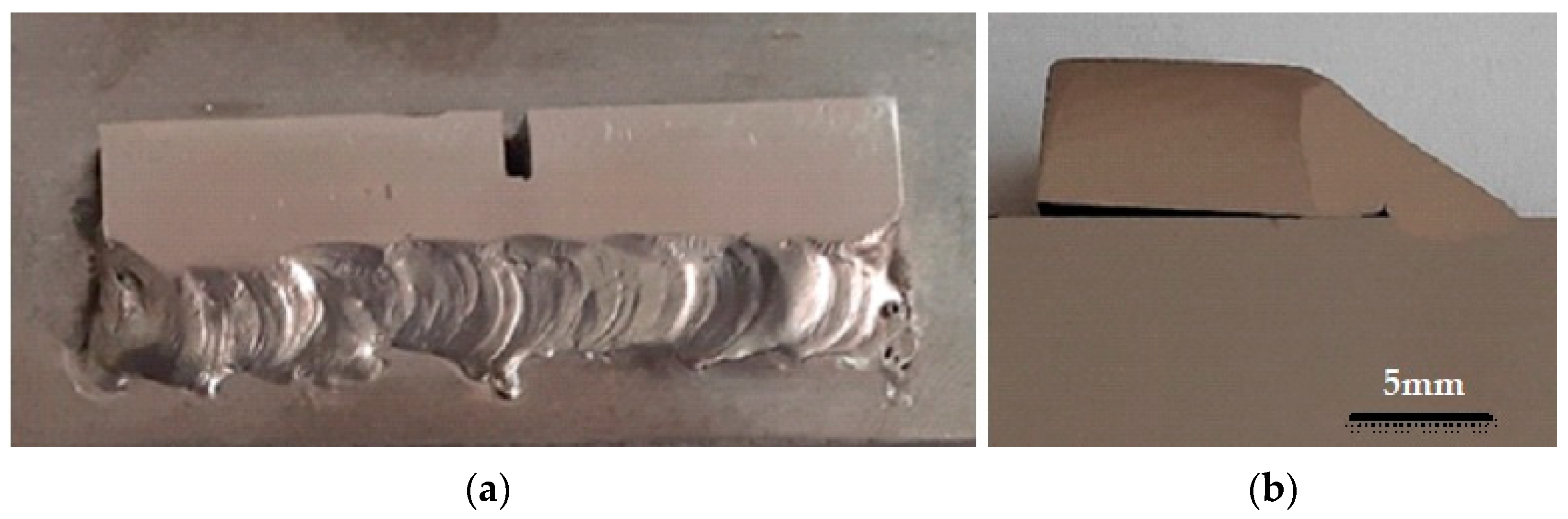
2.3. Welding Process

The HEA plate (5 × 10 × 55 mm) was welded to the larger structural steel plate S235JR (9 × 40 × 110 mm) in a single-fillet lap joint, in two passes, by GMAW. A small notch of 4 mm depth was processed on the HEA alloy plate, with the aim of studying the resistance to cracks propagation determined by the expansion or contraction processes generated during welding (Figure 1). Prior to welding, the oxide layers and other imperfections from the plates’ surfaces were removed by the grinding technique.
Two layers, shown in Figure 1a, were deposited with the PRESTOTIG 210 welding equipment, by applying the following parameters: welding current—90 A, welding voltage—12 V, and high-purity Ar 4.8 gas flow—10 L/min. The first layer was deposited mainly on the edge of the HEA plate, while the second one made the connection between the first layer and the steel component. In the case of dissimilar metals welding, when three different base and filler materials are melted and solidified, a complete homogeneity of the chemical composition in the weld is almost impossible to achieve. The diffusion process is influenced by the mutual solubility and chemical compatibility of the materials, diffusion coefficients of the alloying elements, the temperature reached in the transition zone, and by the time of the reciprocal exchange through the interface between the base and deposited materials. The Ni-rich metal filler metal was selected to ensure the chemical and metallurgical compatibility of the HEA and S235JR alloys, as well as the transition from the base materials to the weld metal. First, a layer of Ni-rich metal was deposited by fusion on the HEA material, followed by depositing the second layer on the structural steel. In fact, there was no direct contact between the HEA and S235JR, with the filler metal acting as a buffer layer with the aim of limiting the carbon diffusion from the carbon steel to the high-entropy alloy. Due to the smaller section of the HEA plate and stresses generated during welding, a slight deformation of this part was observed (Figure 1b). However, the contraction effect, developed during the solidification phase, did not generate cracks either in the weld, in the Heat-Affected Zone (HAZ), or in the notched area.

2.4. Testing Methods

Employing the Buehler IsoMet 4000 (Buehler, Lake Bluff, IL, USA) equipment and applying the cutting speed of 0.12 mm/s, the samples were cut under a coolant jet, so that the material’s microstructure was not affected by heating. The surface imperfections that resulted during the cutting process were removed by using 400-, 600-, 800-, 1000-, and 2500-grit self-adhesive abrasive papers and liquid coolant. The final surfaces processing was performed in more phases by polishing with Topol 1 and Topol 2 powders (suspension alpha alumina with 1 and 0.7 µm granulation), followed by polishing with 0.1 µm CeO2 powder. After polishing, the welded samples were washed with isopropyl alcohol, and then they were chemically etched with 4% nitric acid in ethyl alcohol for nonalloyed steel and oxalic acid 5% for the HEA zone.
Microstructure and chemical composition analysis were investigated in the LAMET Laboratory from University Politehnica of Bucharest, by optical microscopy with an optical microscope equipped with AnalySIS image processing software (Olympus GX 51, Tokyo, Japan), and a scanning electron microscope (Inspect S, FEI, Eindhoven, The Netherlands) equipped with a AMETEC Z2E EDS sensor, respectively. The microhardness testing was made by employing a Shimadzu HMV 2 T microhardness tester (Tokyo, Japan).

3. Results and Discussions

Despite the notch machined in the central area of the HEA sample, which can be considered an important stress intensity factor, no flaw was identified in the weld deposit (WD) by visual examination. Even if there were significant differences between the base materials and filler metal, in terms of mechanical and chemical properties, still no cracks were found in the weld or in the adjacent areas. It can be concluded that the HEA demonstrated a good behavior during welding, with the beneficial role in reducing the oxidation effects of the alloying elements being ensured by the inert gas protection.

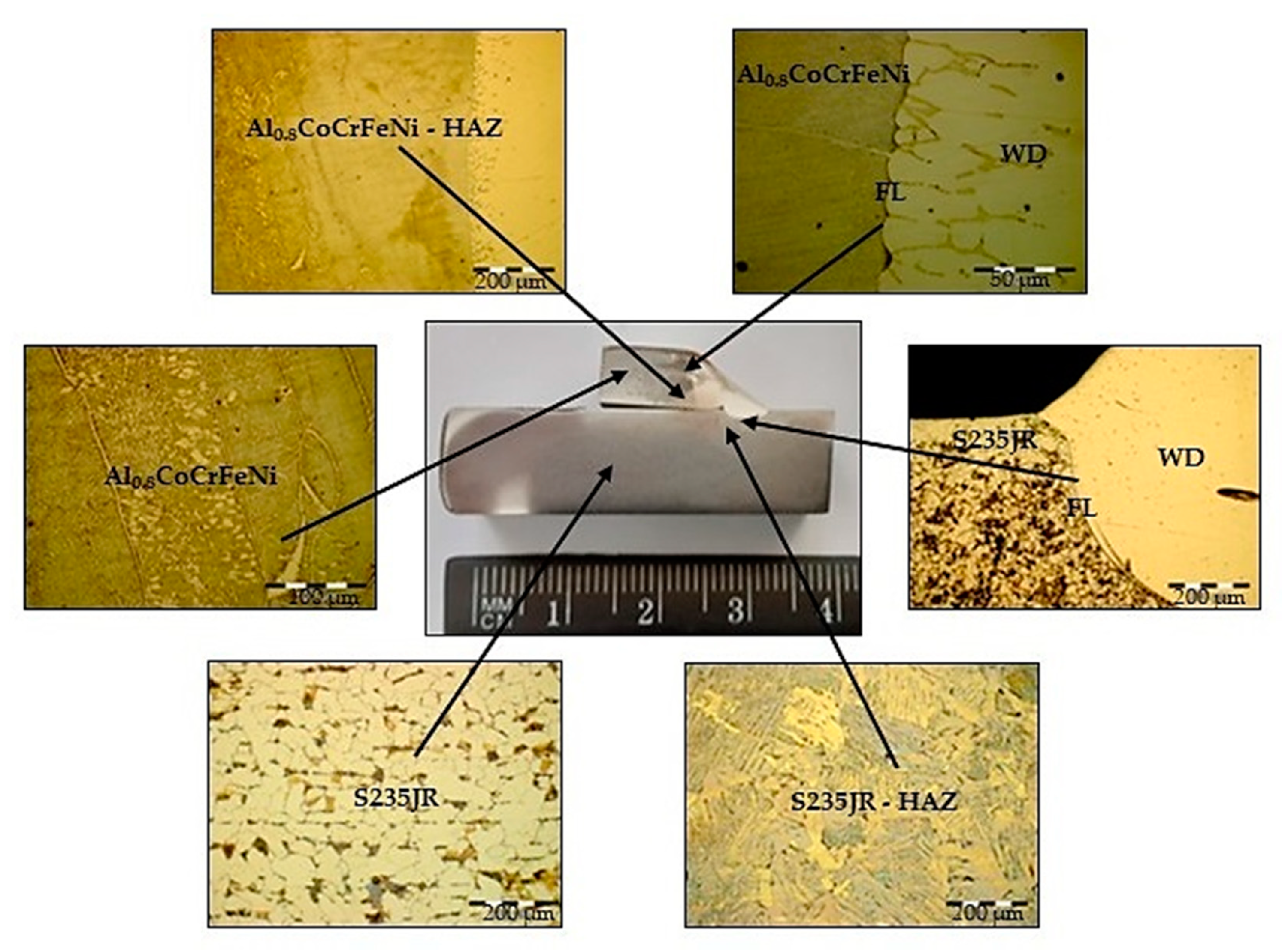
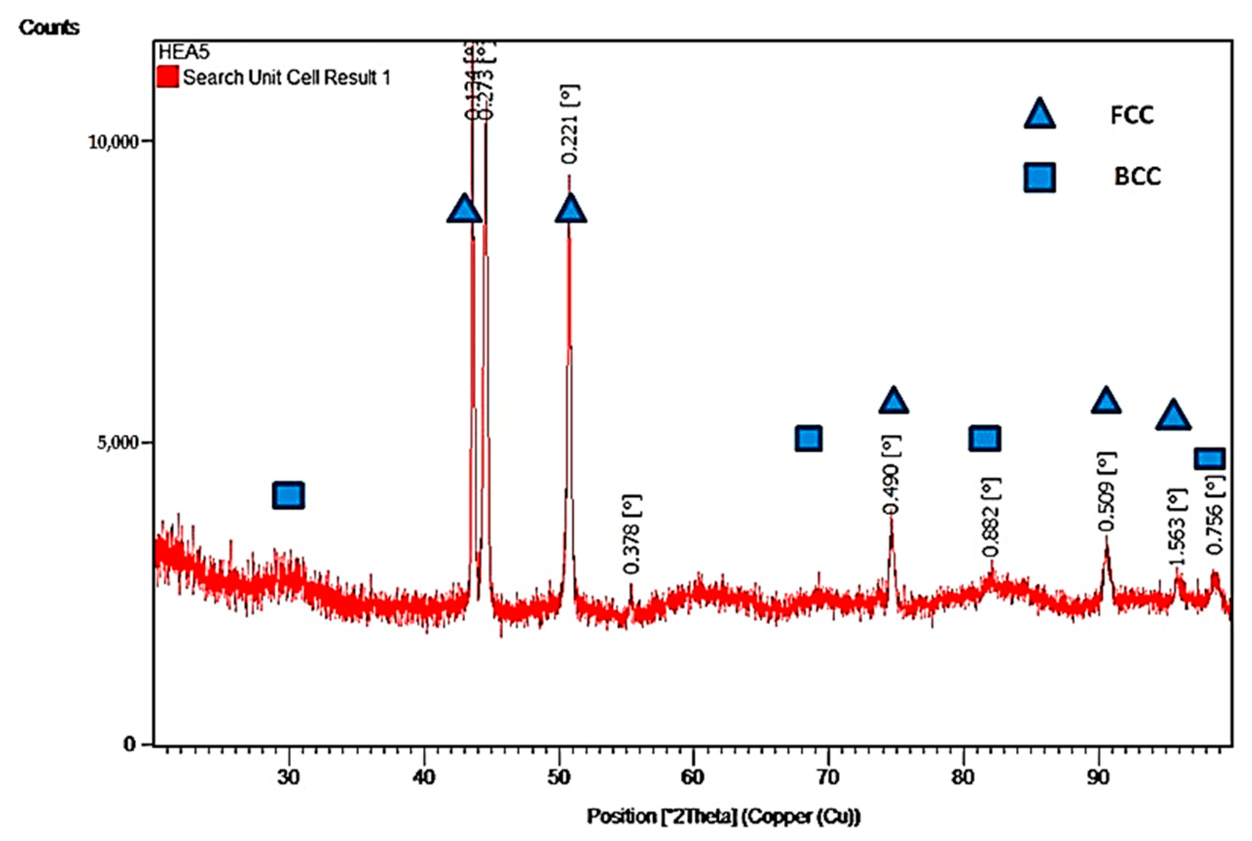
3.1. Microstructure and XRD Analysis

The microstructure analysis was carried out in the cross-section of the welded joint, in order to determine the phases type developed in the WD, the dilution effects, and the possible imperfections that could occur in the melted metal and in the heat-affected zone. As Figure 2 shows, the microstructure found in the substrate material S235JR consists of polyhedral grains of ferrite (light) and pearlite (brown), distributed on parallel layers. An important increase in the granulation average diameter in HAZ, from about 50 µm to about 200 µm, was observed. In addition, a mixture of pro-eutectoid ferrite grains, coarse secondary Widmanstätten ferrite phase, and small grains of pearlite, caused by the modification of phase and proportion, was found in this area [51,52]. A smooth transition, free of imperfections (no fragile phase, cracks, or mixed zones) was observed on the fusion line (FL) between these dissimilar materials.
The effect of the chemical elements on the phases developed in the AlCoCrFeNi alloys was studied by Zhang et al. [53]. The authors found that Ni and Co stabilize the FCC_A1 phase, Fe has a neutral effect, Cr stabilizes the BCC_A2 phase, and Al stabilizes the BCC_B2 phase. On the other hand, the increase in Al content leads to a decrease in the energy difference between the FCC and BCC phases [53]. Moreover, the σ phase may develop in the alloys with a higher content of Cr (25–30 at %) and Co (over 20 at %). The annealing treatment at temperatures above 600 °C can generate a modification of the phases’ ratio based on the stabilization of the FCC phase [11].
According to the previous studies, the differentiation between the phases developed in the alloys specific to the AlxCoCrFeNi system is mainly determined by the Al content. For instance, a single face-centered cubic (FCC) phase is formed when the Al molar fractions are small (x = 0 to 0.375) [4], both FCC duplex and body-centered cubic (BCC) phases are developed when the molar fractions have values in the (x = 0.5 to 0.75) range, while, for large molar fractions (x > 0.875), the researchers identified a single BCC phase [1,2,3,4,9].
In this work, the HEA investigated had a medium atomic molar fraction of Al (x = 0.8), meaning that the alloy belonged to the bi-phase domain, with a typical structure of BCC and FCC phases, but with different percentages. The microstructure comprised a BCC phase of over 72.7%, with grains having an average diameter of 100 µm, and also a separated inter-dendritic FCC phase, but in a smaller percentage (about 27.3%) [4].
In our previous article [54], we studied the phases developed in the AlxCoCrFeNi high-entropy alloy system (x = 0.2; 0.4; 0.6; 0.8; 1; 1.2; 1.4; 1.5; 2). The research was focused on the analysis of phase compounds developed in the Al0.8CrFeCoNi alloy (Figure 3, HEA 5) by employing the Panalytical X’Pert Pro MPD X-ray diffractometer (Lelyweg, Almelo, The Netherlands) with Cu Ka radiation (1.54060 [A]), and the following parameters: θ–2θ: 20–100°, step size (°): 0.01313, time per step (s): 60, scan speed: (°/s): 0.0547 and number of steps: 6093.
The XRD diagram, presented in Figure 3, shows a group of X-ray peaks in the Al0.8CrFeCoNi alloy that corresponds to both α-type—BCC and FCC phases. The crystallite size for this high-entropy alloy was found to be 22.05 nm. Estimation of the phase ratio is supported by similar results reported by Kao et al. in [4] obtained for the Al0.75CoCeFeNi alloy. The overall chemical composition of the Al0.75CoCeFeNi alloy was reported to be Al = 15%; Co = 21.04%; Cr = 22.29%; Fe = 21.16%; Ni = 20.51, in at % [4]. These assumptions are confirmed by the results obtained by Chen [55], Wu [56], Jasiewicz [57], and Dąbrowa [58]. Regarding the Al0.8CoCeFeNi alloy, discussed in this work, the overall chemical composition was found to be: Al = 15.91%; Co = 20.72%; Cr = 22.58%; Fe = 21.37%; Ni = 19.42, in at %.
In the HAZ of the Al0.8CoCrFeNi material, grown grains that suffered an increase in granulation from about 100 µm to over 400 µm, and a homogeneous mixture were detected near the FL that separates the WD and HEA (Figure 2). An inter-penetration and a strong mixing between the HEA and the NiFe-rich alloy were noticed, as well as the presence of dendrites that grew on the HEA grains (Figure 2, FL–HEA). The microstructure of the Al0.8CoCrFeNi alloy showed grains filled with acicular phases and grain boundaries having different thicknesses (Figure 4a,b). The ESD analysis, made on each phase in the as-cast alloy, revealed a low Al concentration (8.86 to 9.81 wt.%), assigned to the grey gamma phase (GP), and a higher Al concentration (10.67 to 11.03 wt.%) on the light alpha phase (AP).
The scientific literature provides analytical relationships that make possible the prediction of the composition in the stainless-steel weld [59]. Based on the weight percentage of ferrite- and austenite-stabilizing elements, the chromium-equivalent (Cre) and nickel-equivalent (Nie), respectively, can be calculated with Equation (1). The Schaeffler diagram, which is built in Cre and Nie coordinates, is a useful tool and can be easily employed for predicting the structure of the stainless-steel welds.
Cre = %Cr + %Mo + 1.5%Si + 0.5%Nb
Nie = %Ni + 30%C + 0.5%Mn
Another important diagram in predicting the constituents in welds is the DeLong diagram, which was developed by refining the ferrite zone of the Schaeffler diagram. Ferrite has an important role in avoiding the hot cracking phenomenon that may occur during cooling from welding of austenitic stainless steels. The Delong diagram shows the ferrite levels in bands, both as percentages, based on metallographic determinations, and as ferrite number (FN), based on magnetic determination methods. The FN number was found to be more accurate in terms of ferrite prediction. The Cre equation is unaffected, but the Nie calculus was modified, according to Equation (2).
Cre = %Cr + %Mo + 1.5%Si + 0.5%Nb
Nie = %Ni + 30%C + 30%N + 0.5%Mn
The WRC-1992 diagram is a rapid way of estimating the ferrite content and represents a solution for many of the unsolved issues by the Schaeffler and DeLong ones. This diagram was developed based on the latest FN definition method, by removing the erroneous Mn coefficient from the Nie Equation (3), and by eliminating the systematic overestimation of the FN for the welded high-alloy steels [26].
Cre = %Cr + %Mo + 0.7%Nb
Nie = %Ni + 35%C + 20%N + 0.25%Cu
As for the high-entropy alloy used in the experiments, due to the high concentration of Ni in filler metal (over 56 wt.%), the main phase developed in the weld metal was austenite. A full austenite structure, validated by the analytical method, was noticed in the first welded layer deposited on the HEA. Based on the Schaeffler diagram, the microstructure was found at the interface between the HEA and the weld metal for different dilution rates. Considering the dilution rate of 10%, the computed values were Cre = 8.35 and Nie = 55.92, while for the 25% dilution rate, the percentages were Cre = 9.47 and Nie = 53.40.
To investigate the dilution effect, a chemical analysis in several spots, located in the zones of the joint (HEA, HAZ, WD), was made on the cross direction on the fusion line, along the distance of 25 µm. A significant modification of chemical composition and formation of elongated Ni3Al phases (13.95 wt.% Al, 41.85 wt.% Ni) was noticed in the weld (Figure 5a). In addition, a decrease in the concentration of Cr and an increase in the concentration of Ni and Al elements were observed on the fusion line (Figure 5b).
Certain chemical elements were maintained in a small concentration range, such as Co, Fe, and Cr, while Al and Ni recorded a larger variation in concentration (Table 2). Aluminium diffused rapidly from the HEA to the weld metal and developed some (Ni, Al)-rich compounds. This phenomenon depends on the temperature reached in the vicinity of the diffusion zone and it was caused by the relatively large mixing enthalpy of the chemical elements [4]. The maximum concentration of Al was measured in the new Ni3Al phase band and reached 13.95 wt.%, which was more than the concentration in the HEA base material, where the Al concentration was 9.28 wt.%.
In the weld area, at about a 12 µm distance from the fusion line, the percentage of Ni was found to be in the range of 25 wt.% and 41.85 wt.%, which is lower than the nominal concentration of 56.4 wt.% from the filler metal. This decrease was caused mainly by the diffusion of Ni and the formation of Ni3Al compound (Table 2, Spot 6) that are characterized by high hardness. The Ni3Al intermetallic phase is usually caused by high-temperature diffusion processes and the reaction between AlNi and Ni [60]. The (Ni, Al)-rich phases were also visible on the distribution maps of chemical elements developed on the fusion line between HEA and weld metal (Figure 6). It was noticed how the Ni- and Al-rich intermetallic phases began to form and increase, as dendrites, from the FL to the weld metal.
A similar analysis was made on the interface between the nonalloy steel S235JR and the stainless-steel weld, on the cross direction on the fusion line (Figure 7), with this case being studied and reported in several scientific articles [39,52]. The microstructure in the weld metal was investigated for two dilution rates by applying the methodology based on the Schaeffler diagram. The resulting structural coefficients were Cre = 7.29 and Nie = 54.08 for 10% dilution, and Cre = 6.82 and Nie = 50.51 when the dilution ratio was considered 25%. The high concentration of Ni had a determinant role in obtaining the fully austenitic structure in the weld area. As it is shown in Figure 6, there was a good connection between the dissimilar base materials. In addition, it was found that the diffusion of chemical elements from stainless steel to low-carbon steel had a small width, which was about 5 µm.
The microstructure analysis showed an approximately 200 μm distance from the fusion line, a narrow nonmixing zone (NM) with an inhomogeneous aspect. An uneven mixture of chemical elements was found by chemical analysis (Figure 7, Table 3). In this narrow nonmixing zone, having a width of about 100 μm, the nickel concentration was very high (over 90 wt.%), resulting in a buffer zone that blocks the diffusion of chemical elements to the unalloyed steel substrate. Below this area, to the fusion line, the concentration of other chemical elements in the deposited metal was almost similar to the nominal values contained by the filler metal. The analysis showed the diffusion of Co and Al between the weld metal and the structural steel on about 200 µm (Figure 7 and Figure 8).

3.2. Hardness

The hardness profile was built based on the measurements made with the Shimadzu HMV 2T microhardness tester (Shimadzu, Duisburg, Germany). A load of 1.961 N was applied, as well as an indentation time of 10 s, to determine the microhardness in five indentations located in each region of the joint (S235 JR, HEA, WD, HAZ of HEA, HAZ of S235JR). The hardness Vickers profile and values (Figure 9, Table 4, respectively) confirm the results reported in the articles [52,59] for the unalloyed steel and for the (Ni, Fe)-rich alloy. In this work, the highest hardness (448 HV0.2) was found in the HAZ of HEA, near the fusion line, caused by the effects generated by the welding process.
As was expected, the hardness values were much different in the areas of the joint, with this phenomenon being typical for the welding of the dissimilar metals. However, the filler metal, appropriately selected to achieve an adequate transition between such different base materials, had a crucial role in avoiding the development of defects, such as cracks or other imperfections. This high-entropy alloy was found to be susceptible to cracking during welding or melting, as it was reported in [46].

4. Conclusions

Several conclusions on the behavior of the Al0.8CoCrFeNi alloy and S235JR steel, welded by the Gas Metal Arc Welding process with high-austenitic filler metal, are briefly presented below:
  • A good metallurgical compatibility between base materials and filler metal, demonstrated by lack of defects, was noticed.
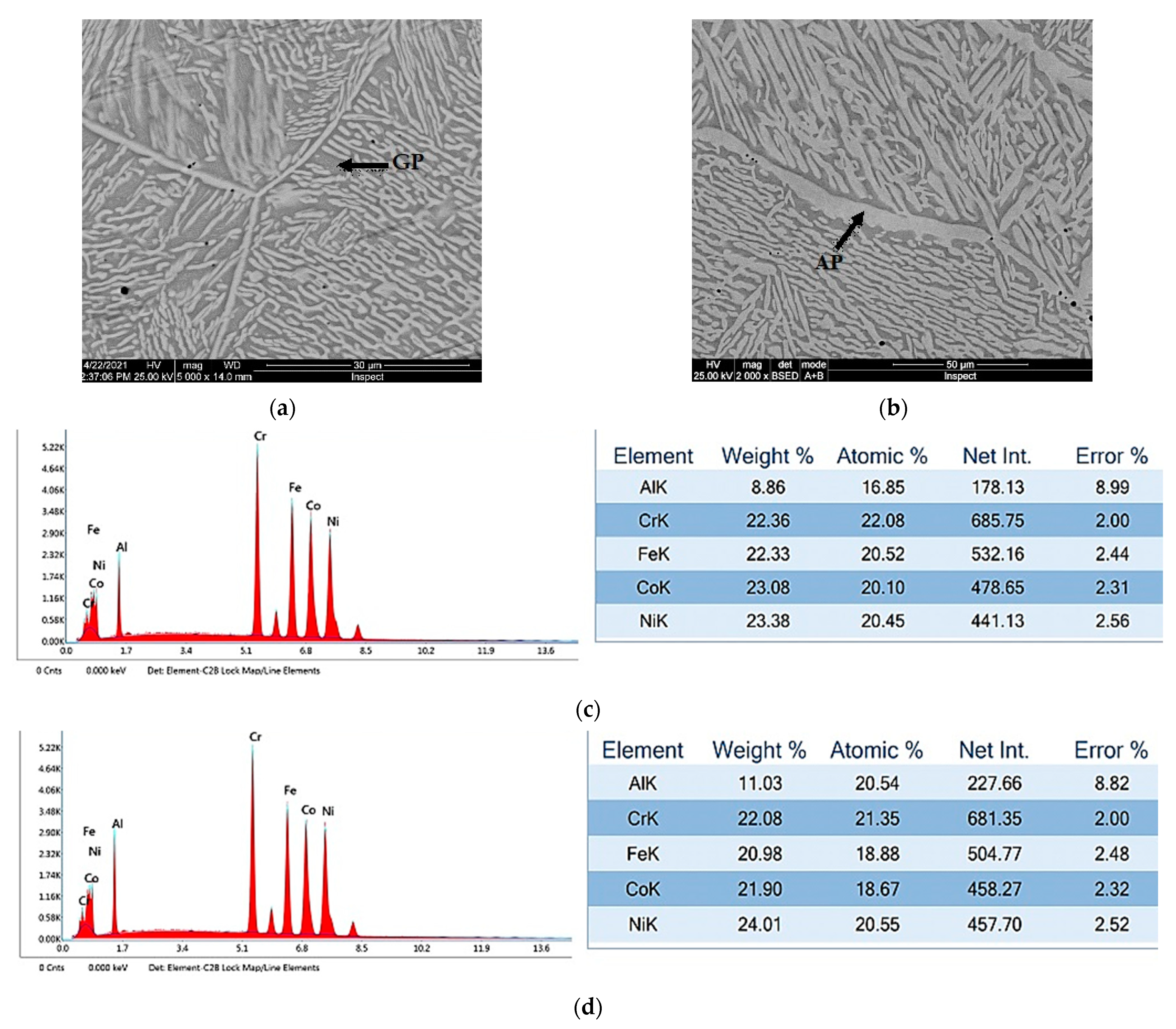
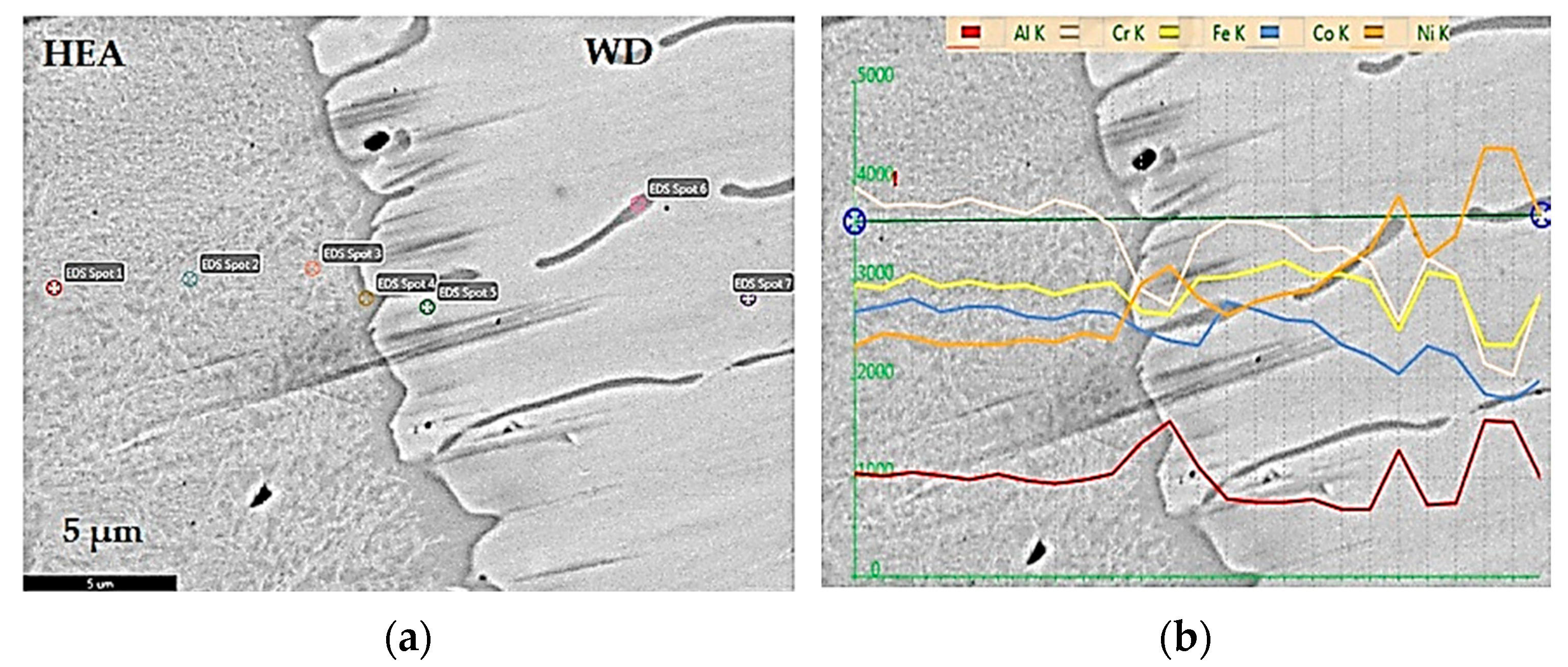
  • Close to the HEA and the weld interface, Ni- and Al-rich intermetallic phases developed and increased, as dendrites, from the fusion line to the weld.
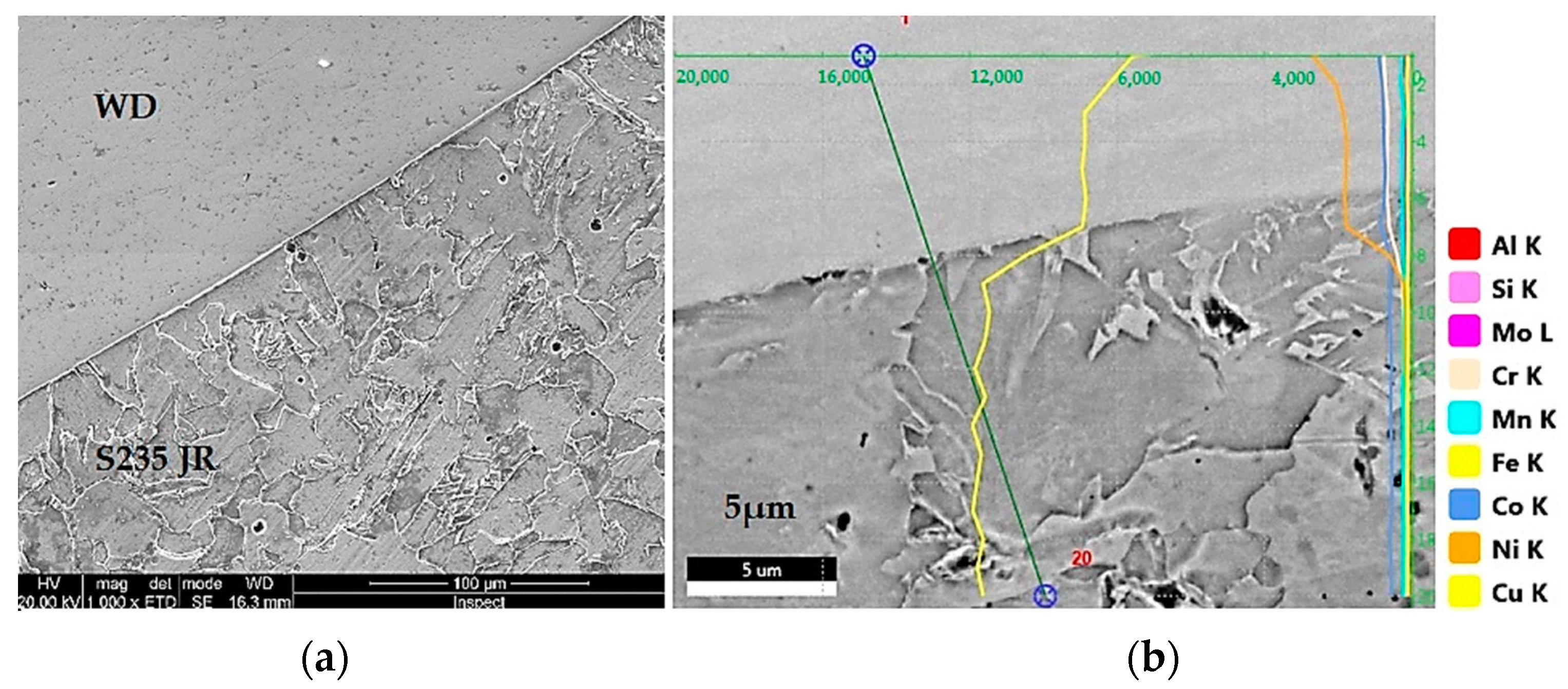
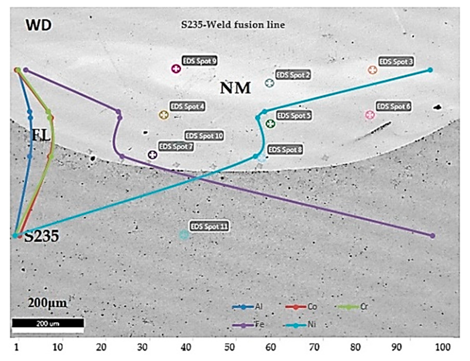
  • Close to the unalloyed steel and the weld interface, a nonmixing zone, located at about 200 μm from fusion line, was found. In this narrow zone that has about a 100 μm width, due to the high Ni concentration (over 99%), the diffusion of chemical elements to the steel substrate was blocked. Below the weld deposit, to the fusion line, the concentration of other chemical elements in the deposited metal was almost similar to the nominal values contained by the filler metal.
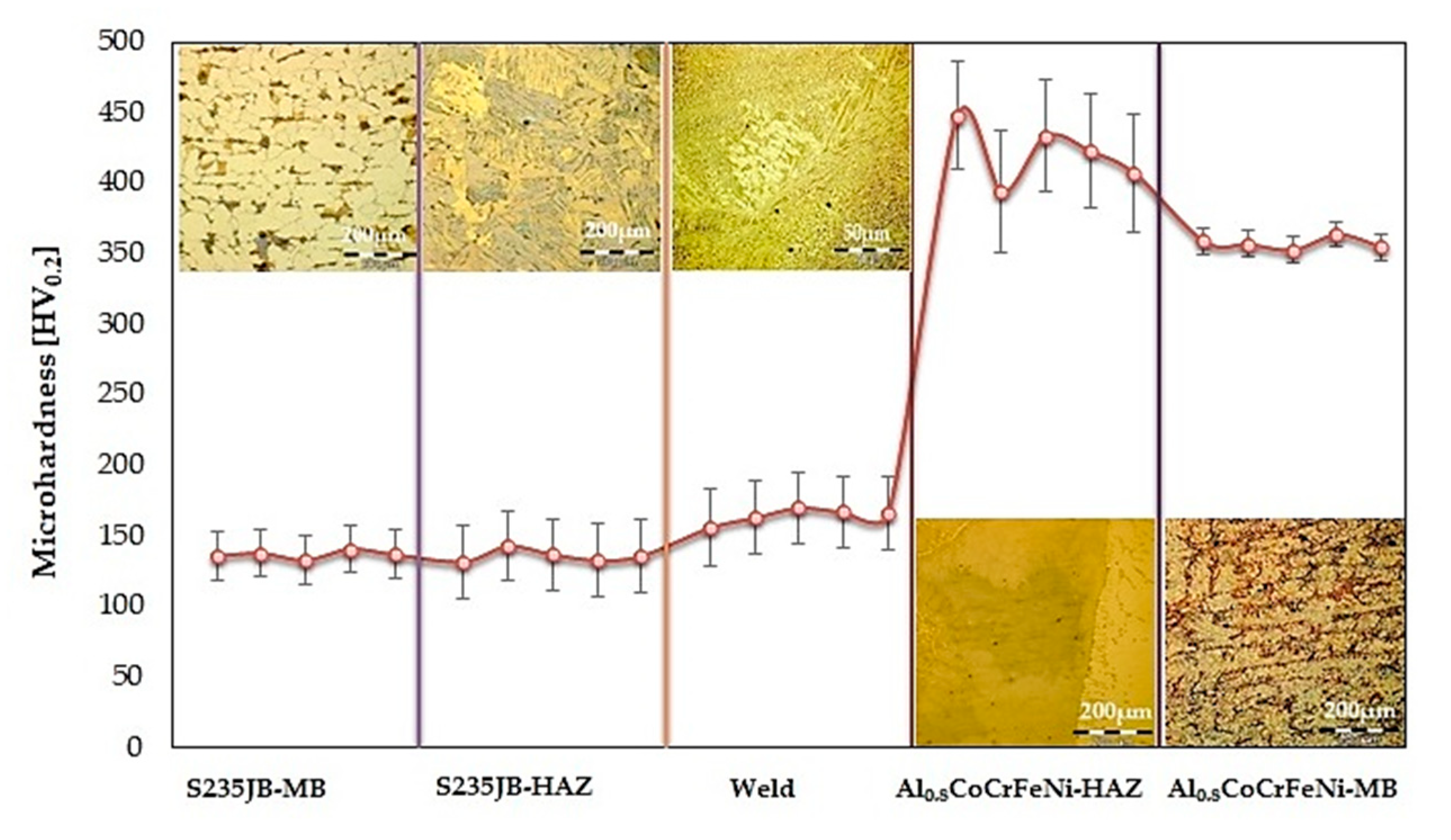
  • The hardness values matched the usual limits, specific to the materials investigated. The maximum average hardness (448 HV0.2) was found in the HAZ of HEA that is usually characterized by an average hardness of 358 HV0.2. This hardness increase was caused by the formation of Ni3Al and NiAl intermetallic phases.

Author Contributions

Conceptualization, methodology, analysis, validation, writing—original draft preparation, supervision, writing—review and editing, I.V. and E.S.; formal analysis, resources, visualization, I.V. and V.G.; investigation, data collection, writing—original draft preparation, E.V.S. and G.S. All authors have read and agreed to the published version of the manuscript.

Funding

This research received no external funding.

Institutional Review Board Statement

Not applicable.

Informed Consent Statement

Not applicable.

Data Availability Statement

Not applicable.

Acknowledgments

The authors gratefully acknowledge the support received from the Romanian National Authority for Scientific Research, CNDI–UEFISCDI, through the project number PN-III-P2-2.1-PED-2019-3953, contract 514PED/2020 “New ceramic layer composite material processed by laser techniques for corrosion and high temperature applications—LASCERHEA”, Romania.

Conflicts of Interest

The authors declare no conflict of interest.

References

  1. Ye, Y.F.; Wang, Q.; Lu, J.; Liu, C.T.; Yang, Y. High-entropy alloy: Challenges and prospects. Mater. Today 2016, 19, 349–362. [Google Scholar] [CrossRef]
  2. Zhang, Y. High-Entropy Materials. A Brief Introduction; Springer Nature: Cham, Switzerland, 2019; pp. 1–33. [Google Scholar]
  3. Cao, L.; Wang, X.; Wang, Y.; Zhang, Y.; Yang, Y.; Liu, F.; Cui, Y. Microstructural evolution, phase formation and mechanical properties of multi-component AlCoCrFeNix alloys. Appl. Phys. A 2019, 125, 699. [Google Scholar] [CrossRef]
  4. Kao, Y.F.; Chen, T.J.; Chen, S.K.; Yeh, J.W. Microstructure and mechanical property of as-cast, -homogenized, and -deformed AlxCoCrFeNi (0 ≤ x ≤ 2) high-entropy alloys. J. Alloys Compd. 2009, 488, 57–64. [Google Scholar] [CrossRef]
  5. Yeh, J.W.; Chen, S.K.; Lin, S.J.; Gan, J.Y.; Chin, T.S.; Shun, T.; Tsau, C.-H.; Chang, S.Y. Nanostructured high-entropy alloys with multiple principal elements: Novel alloy design concepts and outcomes. Adv. Eng. Mater. 2004, 6, 299–303. [Google Scholar] [CrossRef]
  6. Cantor, B.; Chang, I.T.H.; Knight, P.; Vincent, A.J.B. Microstructural development in equiatomic multicomponent alloys. Mater. Sci. Eng. A 2004, 375, 213–218. [Google Scholar] [CrossRef]
  7. Miracle, D.B.; Miller, J.D.; Senkov, O.N.; Woodward, C.; Uchic, M.D.; Tiley, J. Exploration and Development of High Entropy Alloys for Structural Applications. Entropy 2014, 16, 494–525. [Google Scholar] [CrossRef]
  8. Wang, Y.P.; Li, B.S.; Ren, M.X.; Yang, C.; Fu, H.Z. Microstructure and compressive properties of AlCrFeCoNi high entropy alloy. Mater. Sci. Eng. A 2008, 491, 154–158. [Google Scholar] [CrossRef]
  9. Zhang, Y.; Zuo, T.T.; Tang, Z.; Gao, M.C.; Dahmen, K.A.; Liaw, P.K.; Lu, Z.P. Microstructures and properties of high-entropy alloys. Prog. Mater. Sci. 2014, 61, 1–93. [Google Scholar] [CrossRef]
  10. Wang, W.-R.; Wang, W.-L.; Wang, S.-C.; Tsai, Y.-C.; Lai, C.-H.; Yeh, J.-W. Effects of Al addition on the microstructure and mechanical property of AlxCoCrFeNi high-entropy alloys. Intermetallics 2012, 26, 44–51. [Google Scholar] [CrossRef]
  11. Tokarewicz, M.; Gradzka-Dahlke, M. Review of recent research on AlCoCrFeNi high-entropy alloy, Review. Metals 2021, 11, 1302. [Google Scholar] [CrossRef]
  12. Lopez Rios, M.; Perdomo, P.P.S.; Voiculescu, I.; Geanta, V.; Rosca, J.C.M. Effects of nickel content on the microstructure, microhardness and corrosion behavior of high-entropy AlCoCrFeNix alloys. Sci. Rep. 2020, 10, 21119. [Google Scholar] [CrossRef] [PubMed]
  13. Shi, Y.; Yang, B.; Liaw, P.K. Corrosion-Resistant High-Entropy Alloys: A Review. Metals 2017, 7, 43. [Google Scholar] [CrossRef] [Green Version]
  14. Tang, Z.; Huang, L.; He, W.; Liaw, P.K. Alloying and Processing Effects on the Aqueous Corrosion Behavior of High-Entropy Alloys. Entropy 2014, 16, 895–911. [Google Scholar] [CrossRef]
  15. Chou, H.-P.; Chang, Y.-S.; Chen, S.-K.; Yeh, J.-W. Microstructure, thermophysical and electrical properties in AlxCoCrFeNi (0 ≤ x ≤ 2) high-entropy alloys. Mater. Sci. Eng. B 2009, 163, 184–189. [Google Scholar] [CrossRef]
  16. Li, A.; Zhang, X. Thermodynamic analysis of the simple microstructure of AlCrFeNiCu high-entropy alloy with multi-principal elements. Acta Metall. Sin. (Engl. Lett.) 2009, 22, 219–224. [Google Scholar] [CrossRef] [Green Version]
  17. Miracle, D.B.; Senkov, O.N. A critical review of high entropy alloys and related concepts. Acta Mater. 2017, 122, 448–511. [Google Scholar] [CrossRef] [Green Version]
  18. Murty, B.S.; Yeh, J.W.; Ranganathan, S.; Bhattacharjee, P.P. High-Entropy Alloys, 2nd ed.; Elsevier: Amsterdam, The Netherlands, 2008. [Google Scholar]
  19. Miracle, D.B. Critical assessment 14: High entropy alloys and their development as structural materials. Mater. Sci. Technol. 2015, 31, 1142–1147. [Google Scholar] [CrossRef] [Green Version]
  20. Hsieh, K.C.; Yu, C.F.; Hsieh, W.T.; Chiang, W.R. The microstructure and phase equilibrium of new high performance high-entropy alloys. J. Alloys Compd. 2009, 483, 209–212. [Google Scholar] [CrossRef]
  21. Voiculescu, I.; Geanta, V.; Stefanoiu, R.; Patroi, D.; Binchiciu, H. Influence of the Chemical Composition on the Microstructure and Microhardness of AlCrFeCoNi High Entropy Alloy. Rev. Chim. 2014, 64, 1441–1444. [Google Scholar]
  22. Geanta, V.; Chereches, T.; Lixandru, P.; Voiculescu, I.; Stefanoiu, R.; Dragnea, D.; Zecheru, T.; Matache, L. Virtual Testing of Composite Structures Made of High Entropy Alloys and Steel. Metals 2017, 7, 496. [Google Scholar] [CrossRef] [Green Version]
  23. Munitz, A.; Salhov, S.; Guttmann, G.; Derimow, N.; Nahmany, M. Heat treatment influence on the microstructure and mechanical properties of AlCrFeNiTi0.5 high entropy alloys. J. Mater. Sci. Eng. A 2019, 742, 1–14. [Google Scholar] [CrossRef]
  24. Munitz, A.; Salhov, S.; Hayun, S.; Frage, N. Heat treatment impacts the micro-structure and mechanical properties of AlCoCrFeNi high entropy alloy. J. Alloys Compd. 2016, 683, 221–230. [Google Scholar] [CrossRef]
  25. Wang, W.R.; Wang, W.L.; Yeh, J.W. Phases, microstructure and mechanical properties of AlxCoCrFeNi high-entropy alloys at elevated temperatures. J. Alloys Compd. 2014, 589, 143–152. [Google Scholar] [CrossRef]
  26. Tsai, M.H.; Yeh, J.W. High-entropy alloys: A critical review. Mater. Res. Lett. 2014, 2, 107–123. [Google Scholar] [CrossRef]
  27. Guo, J.; Tang, C.; Rothwell, G.; Li, L.; Wang, Y.C.; Yang, Q.; Ren, X. Welding of High Entropy Alloys—A Review. Entropy 2019, 21, 431. [Google Scholar] [CrossRef] [Green Version]
  28. Scutelnicu, E.; Simion, G.; Rusu, C.C.; Gheonea, M.C.; Voiculescu, I.; Geanta, V. Review of High Entropy Alloys Behaviour during Welding. Rev. Chim. 2020, 71, 219–233. [Google Scholar] [CrossRef]
  29. Zhang, Y.; Jiang, X.; Fang, Y.; Fang, Y.; Liu, B.; Sun, H.; Shao, Z.; Song, T. Research and development of welding methods and welding mechanism of high-entropy alloys: A review. Mater. Today Commun. 2021, 28, 102503. [Google Scholar] [CrossRef]
  30. Voiculescu, I.; Geanta, V.; Vasile, I.M.; Stefanoiu, R.; Tonoiu, M. Characterisation of weld deposits using as filler metal a high entropy alloy. J. Optoelectron. Adv. Mater. 2013, 15, 650–654. [Google Scholar]
  31. Zhang, G.J.; Tian, Q.W.; Yin, K.X.; Niu, S.Q.; Wu, M.H.; Wang, W.W.; Wang, Y.N.; Huang, J.C. Effect of Fe on microstructure and properties of AlCoCrFexNi (x=1.5, 2.5) high entropy alloy coatings prepared by laser cladding. Intermetallics 2020, 119, 106722. [Google Scholar] [CrossRef]
  32. Sokkalingam, R.; Muthupandi, V.; Sivaprasad, K.; Prashanth, K.G. Dissimilar welding of Al0.1CoCrFeNi high-entropy alloy and AISI304 stainless steel. J. Mater. Res. 2019, 34, 2683–2694. [Google Scholar] [CrossRef]
  33. Sokkalingam, R.; Mastanaiah, P.; Muthupandi, V.; Sivaprasad, K.; Prashanth, K.G. Electron-beam welding of high-entropy alloy and stainless steel: Microstructure and mechanical properties. Mater. Manuf. Process. 2020, 35, 1885–1894. [Google Scholar] [CrossRef]
  34. Sokkalingam, R.; Sivaprasad, K.; Muthupandi, V. Welding of High Entropy Alloys. Techniques, Advantages, and Applications: A Review. In Welding of High Entropy Alloys. Techniques, Advantages, and Applications, 1st ed.; Srivatsan, T.S., Gupta, M., Eds.; CRC Press: Boca Raton, FL, USA, 2020; pp. 597–651. [Google Scholar]
  35. Constantin, G.; Balan, E.; Voiculescu, I.; Geanta, V.; Craciun, V. Cutting behavior of Al0.6CoCrFeNi High Entropy Alloy. Materials 2020, 13, 4181. [Google Scholar] [CrossRef] [PubMed]
  36. Hsu, C.Y.; Sheu, T.S.; Yeh, J.W.; Chen, S.K. Effect of iron content on wear behavior of AlCoCrFexMo0.5Ni high-entropy alloys. Wear 2010, 268, 653–659. [Google Scholar] [CrossRef]
  37. Shun, T.T.; Hung, C.H.; Lee, C.F. The effects of secondary elemental Mo or Ti addition in Al0.3CoCrFeNi high-entropy alloy on age hardening at 700 °C. J. Alloys Compd. 2010, 495, 55–58. [Google Scholar] [CrossRef]
  38. Manzoni, A.; Daoud, H.; Volkl, R.; Glatzel, U.; Wanderka, N. Phase separation in equiatomic AlCoCrFeNi high-entropy alloy. Ultramicroscopy 2013, 132, 212–215. [Google Scholar] [CrossRef]
  39. Qin, G.; Xue, W.; Fan, C.; Chen, R.; Wang, L.; Su, Y.; Ding, H.; Guo, J. Effect of Co content on phase formation and mechanical properties of (AlCoCrFeNi)100-xCox high-entropy alloys. Mater. Sci. Eng. A 2018, 710, 200–205. [Google Scholar] [CrossRef]
  40. Kumar, S.; Patnaik, A.; Pradhan, A.K.; Kumar, V. Effect of Cobalt content on thermal, mechanical, and microstructural properties of Al0.4FeCrNiCox (x = 0, 0.25, 0.5, 1.0 mol) high-entropy alloys. J. Mater. Eng. Perform. 2019, 28, 4111–4119. [Google Scholar] [CrossRef]
  41. Tsai, M.H.; Yuan, H.; Cheng, G.; Xu, W.; Jian, W.W.; Chuang, M.H.; Juan, C.C.; Yeh, A.C.; Lin, S.J.; Zhu, Y. Significant hardening due to the formation of a sigma phase matrix in a high entropy alloy. Intermetallics 2013, 33, 81–86. [Google Scholar] [CrossRef]
  42. Zhang, M.; Wang, D.; He, L.; Ye, X.; Zhang, W. Laser beam welding of AlCoCrFeNi2.1 eutectic high-entropy alloy. Mater. Lett. 2021, 308, 131137. [Google Scholar] [CrossRef]
  43. Sokkalingam, R.; Mishra, S.; Cheethirala, S.R.; Muthupandi, V.; Sivaprasad, K. Enhanced Relative Slip Distance in Gas-Tungsten-Arc-Welded Al0.5CoCrFeNi High-Entropy Alloy. Met. Mater. Trans. A Phys. Metall. Mater. Sci. 2017, 48, 3630–3634. [Google Scholar] [CrossRef]
  44. Sokkalingam, R.; Sivaprasad, K.; Duraiselvam, M.; Muthupandi, V.; Prashanth, K.G. Novel welding of Al0.5CoCrFeNi high-entropy alloy: Corrosion behavior. J. Alloys Compd. 2020, 817, 153163. [Google Scholar] [CrossRef]
  45. Rhode, M.; Richter, T.; Schroepfer, D.; Manzoni, A.M.; Schneider, M.; Laplanche, G. Welding of high-entropy alloys and compositionally complex alloys—An overview. Weld. World 2021, 65, 1645–1659. [Google Scholar] [CrossRef]
  46. Nahmany, M.; Hooper, Z.; Stern, A.; Geanta, V.; Voiculescu, I. AlxCrFeCoNi high-entropy alloys: Surface modification by electron beam bead-on-plate melting. Metallogr. Microstruct. Anal. 2016, 5, 229–240. [Google Scholar] [CrossRef]
  47. Martin, A.C.; Oliveira, J.P.; Fink, C. Elemental effects on weld cracking susceptibility in AlxCoCrCuyFeNi high-entropy alloy. Met. Mater Trans. A 2019, 51A, 778–787. [Google Scholar]
  48. Arab, A.; Guo, Y.; Zhou, Q.; Chen, P. Joining AlCoCrFeNi high entropy alloys and Al-6061 by explosive welding method. Vacuum 2020, 174, 109221. [Google Scholar] [CrossRef]
  49. Li, P.; Sun, H.; Wang, S.; Hao, X.; Dong, H. Rotary friction welding of AlCoCrFeNi2.1 eutectic high entropy alloy. J. Alloys Compd. 2020, 814, 152322. [Google Scholar] [CrossRef]
  50. Li, P.; Wang, S.; Xia, y.; Hao, X.; Dong, H. Diffusion bonding of AlCoCrFeNi2.1 eutectic high entropy alloy to TiAl alloy. J. Mater. Sci. Technol. 2020, 45, 59–69. [Google Scholar] [CrossRef]
  51. Kral, M.V. Phase Transformations in Steels. Fundamentals and Diffusion-Controlled Transformations; Woodhead Publishing Series in Metals and Surface Engineering: Cambridge, UK, 2012; Volume 1, pp. 225–275. [Google Scholar]
  52. Ali, A.; Bhadeshia, H.K.D.H. Microstructure of high strength steel refined with intergranulary nucleated Widmanstatten ferrite. Mater. Sci. Technol. 1991, 7, 895–903. [Google Scholar] [CrossRef]
  53. Zhang, C.; Zhang, F.; Diao, H.; Gao, M.C.; Tang, Z.; Poplawsky, J.D.; Liaw, P.K. Understanding phase stability of Al-Co-Cr-Fe-Ni high entropy alloys. Mater. Des. 2016, 109, 425–433. [Google Scholar] [CrossRef] [Green Version]
  54. Geanta, V.; Voiculescu, I.; Miloșan, I.; Istrate, B.; Mateş, I.M. Chemical Composition Influence on Microhardness, Microstructure and Phases Morphology of AlxCrFeCoNi High Entropy Alloys. Rev. Chim. 2018, 69, 798–801. [Google Scholar] [CrossRef]
  55. Chen, C.; Pang, S.; Cheng, Y.; Zhang, T. Microstructure and mechanical properties of Al20−xCr20+0.5xFe20Co20Ni20+0.5x high entropy alloys. J. Alloys Compd. 2016, 659, 279–287. [Google Scholar] [CrossRef]
  56. Wu, Z.; Bei, H.; Otto, F.; Pharr, G.M.; George, E.P. Recovery, recrystallization, grain growth and phase stability of a family of FCC-structured multi-component equiatomic solid solution alloys. Intermetallics 2014, 46, 121–140. [Google Scholar] [CrossRef]
  57. Jasiewicz, K.; Cieslak, J.; Kaprzyk, S.; Tobola, J. Relative crystal stability of AlxFeNiCrCo high entropy alloys from XRD analysis and formation energy calculation. J. Alloys Compd. 2015, 648, 307–312. [Google Scholar] [CrossRef]
  58. Dabrowa, J.; Danielewski, M. State-of-the-Art Diffusion Studies in the High Entropy Alloys. Metals 2020, 347, 347. [Google Scholar] [CrossRef] [Green Version]
  59. Kotecki, D.J.; Siewert, T.A. WRC-1992 Constitution Diagram for Stainless Steel Weld Metals: A Modification of the WRC-1988 Diagram. Weld. Res. Suppl. 1992, 71, 171–178. [Google Scholar]
  60. Kwiecien, I.; Bobrowski, P.; Wierzbicka-Miernik, A.; Litynska-Dobrzynska, L.; Wojewoda-Budka, J. Growth Kinetics of the Selected Intermetallic Phases in Ni/Al/Ni System with Various Nickel Substrate Microstructure. Nanomaterials 2019, 9, 134. [Google Scholar] [CrossRef] [PubMed] [Green Version]
Figure 1. Aspect of the welded joint between HEA and S235JR substrate (a) and cross-sectional sample prepared for metallographic analysis (b).
Metals 12 00548 g001
Figure 2. Optical microstructure of specific areas of the welded joint: BM—base material; HAZ—Heat-Affected Zone; FL—Fusion Line; WD—Weld Deposit.
Metals 12 00548 g002
Figure 3. XRD diagram for Al0.8CrFeCoNi high-entropy alloy.
Metals 12 00548 g003
Figure 4. SEM microstructure of HEA sample: (a) longitudinal and (b) transversal cross-sections; (c) EDS analysis on gamma phase (GP) and (d) alpha phase (AP).
Metals 12 00548 g004
Figure 5. Distribution of the main chemical elements through the fusion line between HEA and weld metals: (a) HAZ—Spot 1 to 3; FL—Spot 4; WD—Spot 5 to 7; (b) chemical elements modification on the cross direction on the fusion line.
Metals 12 00548 g005
Figure 6. Elements distribution maps on fusion line between HEA and weld deposit.
Metals 12 00548 g006
Figure 7. Transition from weld metal to S235 JR: (a) fusion line between WD and unalloyed steel; (b) distribution of the main chemical elements in this area.
Metals 12 00548 g007
Figure 8. Chemical composition analysis near the fusion line between weld and S235 JR steel.
Metals 12 00548 g008
Figure 9. Hardness profile in the regions of the welded joint.
Metals 12 00548 g009
Table 1. Chemical composition of the experimental HEA: designed and determined by analysis.
Al0.8CoCrFeNi AlloyChemical Elements, wt.%
AlCoCrFeNi
Designed8.722122.6123.8223.85
Spark-spectrometer9.2821.1222.5823.6023.42
Spectrolab M109.5221.0822.0523.2224.13
Table 2. Chemical composition measured in different spots, corresponding to Figure 4b.
Measuring SpotMeasuring ZoneChemical Element Concentration, wt.%
AlCoCrFeNi
Spot 1HEA–HAZ8.3223.6822.7623.1322.11
Spot 29.1025.5524.1625.4215.77
Spot 39.4524.9124.8525.1115.68
Spot 4FL10.3222.0621.5221.9224.17
Spot 5FL near to WD9.0821.4420.7823.6325.07
Spot 6Ni3Al13.9514.6312.5117.0641.85
Spot 7WD6.2420.2119.723.8030.05
Table 3. Chemical composition, wt.%, in the measurement points shown in Figure 8.
SpotZoneAlCoCrFeNiOther Elements
Spot 9NM0.60-0.280.7998.33
Spot 21.241.071.364.4291.91
Spot 30.7-0.592.1896.53
Spot 4WD3.427.597.7023.7857.51
Spot 5near FL3.547.957.8224.4056.29
Spot 63.608.748.3423.9155.41
Spot 7FL3.397.597.8826.6354.52
Spot 83.608.578.7022.8056.33
Spot 11S235JR0.691.08-96.19-Si 0.67; Mn 0.76; Cu 0.61
Table 4. Microhardness values, HV0.2.
ZoneMicrohardnessAverage ValueCoefficient of Variation
S235JR136, 138, 133, 141, 1371372.13
HEA359, 357, 353, 364, 3553581.18
WD156, 163, 170, 167, 1661643.24
HAZ of HEA448, 394, 434, 423, 4074215.07
HAZ of S235JR132, 143, 137, 133, 1361363.18
Publisher’s Note: MDPI stays neutral with regard to jurisdictional claims in published maps and institutional affiliations.

