
A Review on Material Extrusion Additive Manufacturing of Metal and How It Compares with Metal Injection Moulding


Abstract
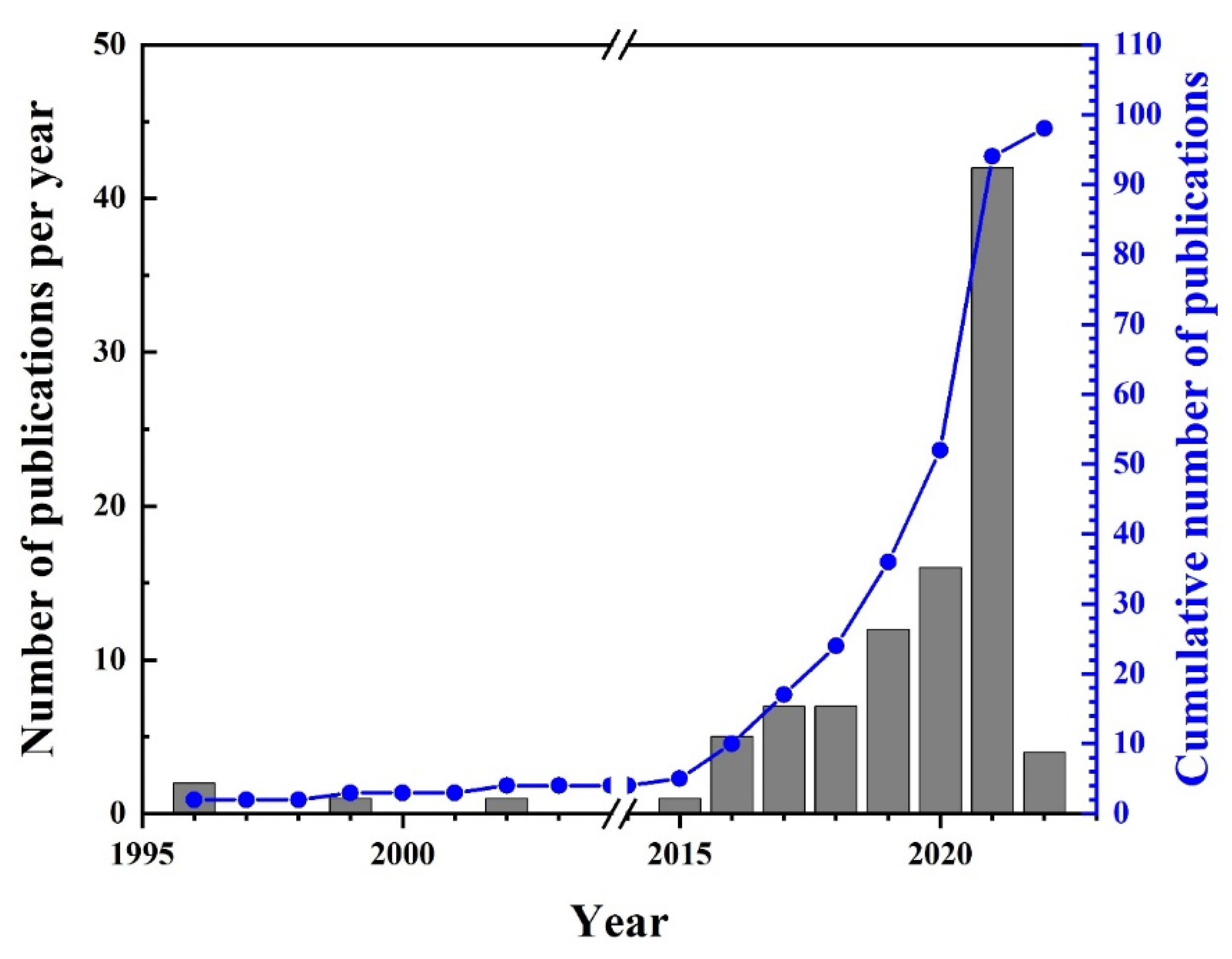
:1. Introduction
2. Material Extrusion Additive Manufacturing of Metal (Metal MEX)
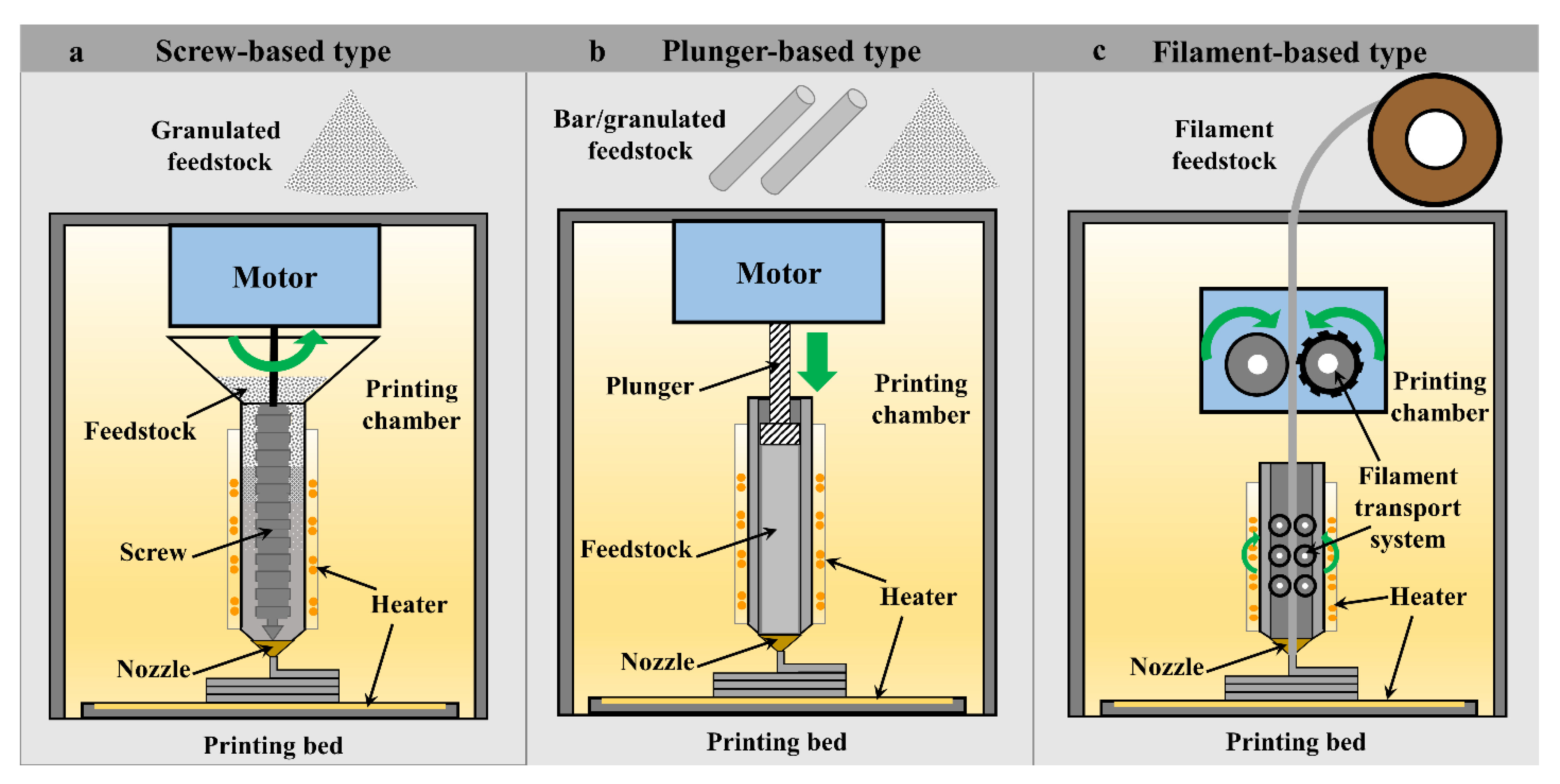
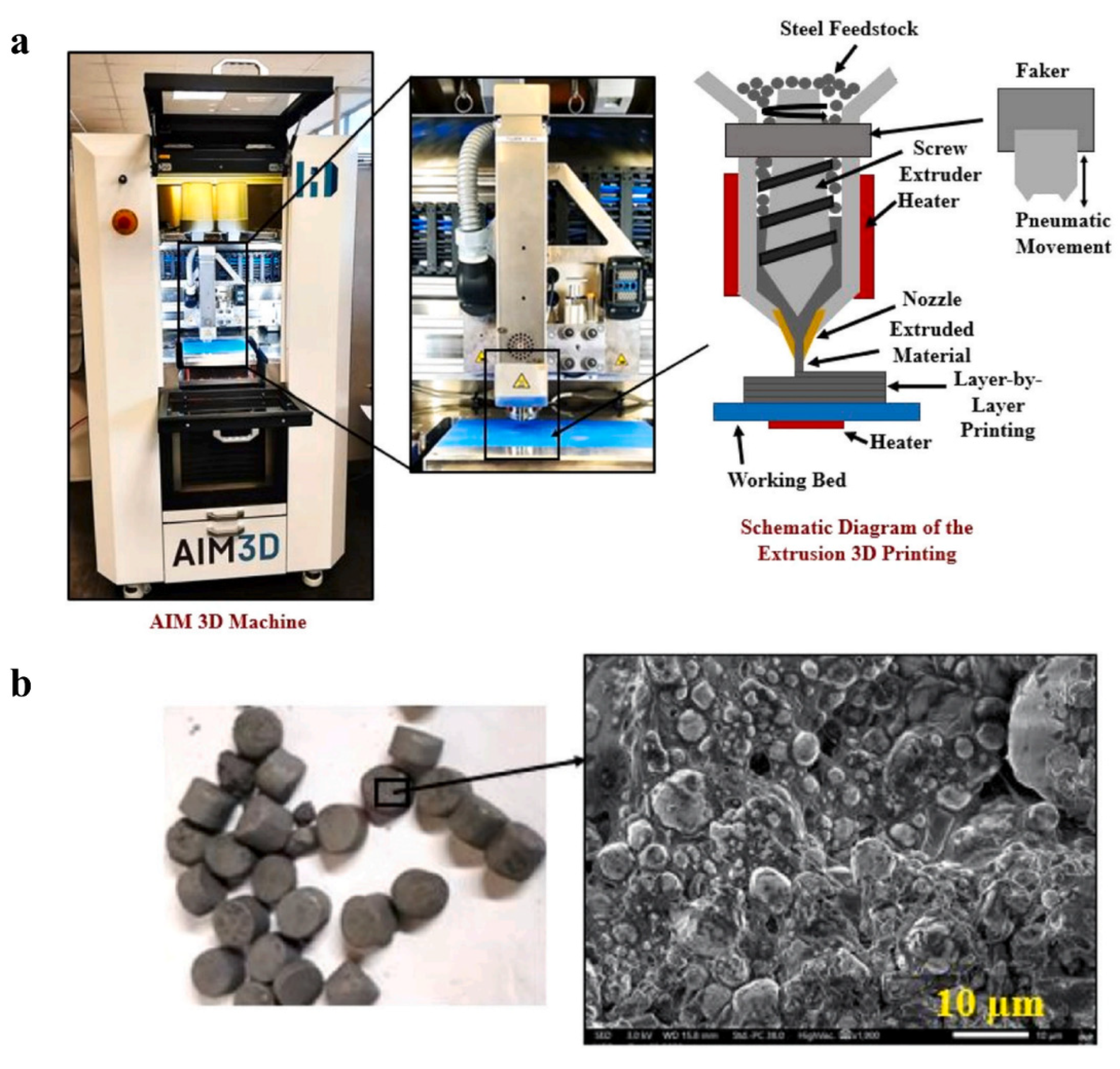
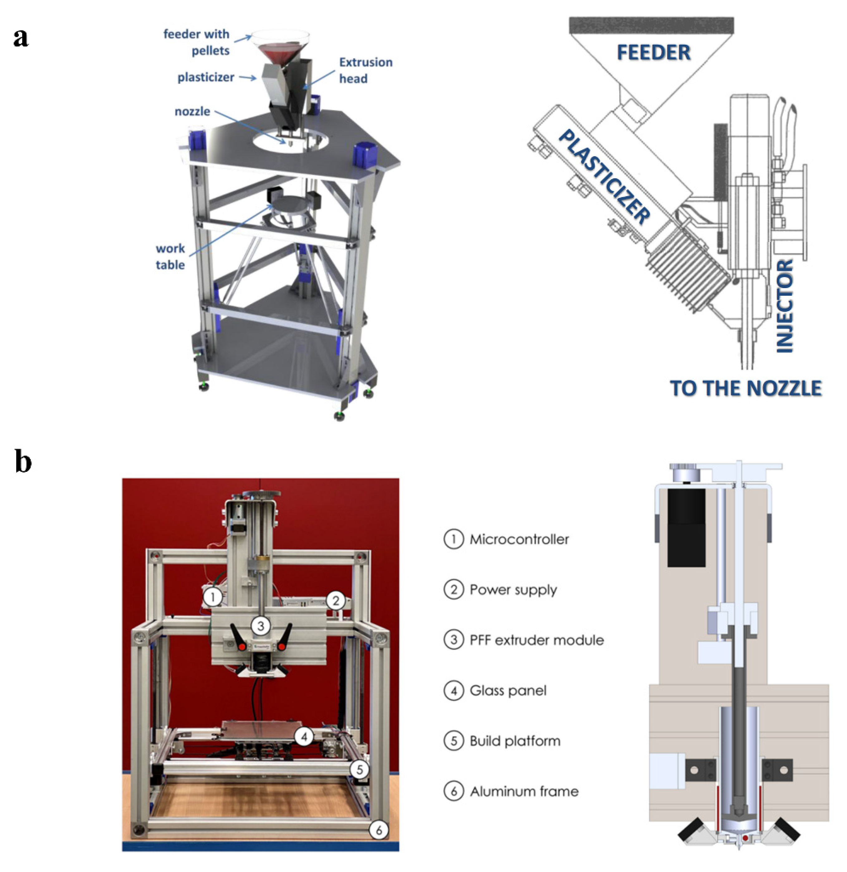
- Screw-based MEX (SB)
- Plunger-based MEX (PB)
- Filament-based MEX (FB)
2.1. Printer
2.2. Feedstock

| Alloys | Powder Characteristics | Solid Loading (Vol.%) | Binder Detail | Debinding Process | Sintering Process | Shrinkage (%) | Relative Density (%) | UTS and % El | Ref. |
|---|---|---|---|---|---|---|---|---|---|
| 17-4PH |
| 93 wt.% | PW, SA, PE |
|
| ND | 97 98 | Was-sintered = 1000 MPa, 8.8% W900 = 1280 MPa, 8% W1100 = 1100 MPa, 11.5% Gas-sintered = 1050 MPa, 8% G900 = 1300 MPa, 10% G1100 = 1080 MPa, 14% | [157] |
| 17-4PH | Water-atomised powder D50 = 9.77 µm | 60 | PA-based, Mould Research, Co., Ltd., Japan |
| ND | 15.7 | 97.5 | 896 MPa, 9.9% | [158] |
| 17-4PH | Water-atomised powder D50 = 9.77 µm | ND | ND |
|
| 13.03–15.64 | 98.8–99 | 900 MPa, 6% | [134] |
| 17-4PH (MPIF 35) | - | - | - | - | - | 12–20 (* 15–18) | 96.7 | 790 MPa, 4% (* 900 MPa, 6%) | [169] |
| 17-4PH Heat treat 900 °F (MPIF 35) | - | - | - | - | - | 12–20 (* 15–18) | 96.7 | 1070 MPa, 4% (* 1190 MPa, 6%) | [169] |
| 316L | Irregular powder, D50 = 10.21 µm | 93wt. (62 vol.%) | LDPE, HDPE, PW, SA |
|
| 14.84–19.43 | 95.4–97.2 | ND | [159] |
| 316L | GA powder (80% < 22 µm) | 60 | Acrylic resin and cyclohexyl methacrylate (CHMA) |
|
| ND | 95 | 450 MPa, 30% | [160] |
| 316L |
| 65 | 50% PW, 40% PP, 10% linear LDPP |
|
| ND | PA-16, 1340 °C, 95.45 PA-22, 1340 °C, 97.8 PA-16, 1360 °C, 97.9 PA-22, 1360 °C, 99.1 MA-16, 1340 °C,98.35 MA-22, 1340 °C,97.72 MA-16, 1360 °C, 98.2 MA-22, 1360 °C, 97.7 | 581.1 MPa, 57.2% 587.0 MPa, 60.6% 581.3 MPa, 56.3% 582.5 MPa, 60.2% 541.0 MPa, 44.2% 527.7 MPa, 43.6% 534.2 MPa, 56.1% 536.5 MPa, 54.3% | [161] |
| 316L (MPIF 35) | - | - | - | - | - | 12–20 (* 15–18) | 96.6 | 450 MPa, 40% (* 520 MPa, 50%) | [169] |
| Ti-6Al-4V | GA powder, D50 = 31.43 µm | 65 | 69% PW, 10% CW, 10% APP, 10% EVA, 1% DBP |
|
| ND | 96 | 910 MPa, 15% | [170] |
| Ti-6Al-4V | GA powder, D50 = 28.8 µm | 65 | 69% PW, 10% CW, 10% APP, 10% EVA, 1% DBP |
|
| ND | 97.4 | 840 MPa, 15% | [163] |
| Ti-6Al-4V | GA powder, D50 = 28.8 µm | 65 | 69% PW, 10% CW, 10% APP, 10% EVA, 1% DBP |
|
| ND | 98.8 | 925 MPa, 18% | [163] |
| Ti-6Al-4V | GA powder, <45 µm | 65 | 60% PW, 35% EVA, 5% SA |
| 1250 °C, 2 h | ND | 96.4 | 824 MPa, 13.4% | [164] |
| Ti-6Al-4V | GA powder, <45 µm | 69 | 60% PW, 35% EVA, 5% SA |
| 1250 °C, 2 h | ND | 96.6 | 806 MPa, 13.7% | [164] |
| Ti-6Al-4V | GA powder, <45 µm | 68 | PW, PE, SA |
| 1250 °C, 2 h | ND | 96.5 | 800 MPa, 15% | [171] |
| Ti-6Al-4V (JPMA) | - | - | - | - | - | - | 95 | 800 MPa, 5% | [172] |
| Type of Printing | Alloys | Powder Characteristics | Solid Loading | Binder | Feedstock | Debinding Process | Ref. |
|---|---|---|---|---|---|---|---|
| Screw-based | 17-4PH | SP (2 to 10 µm) | 93.5 wt.% | PEG and wax | MIM feedstock (PolyMIM) |
| [41,92] |
| Screw-based | 316L | ND | 55 vol.% | Thermoplastic | MIM feedstock (3 mm granule size) |
| [41] |
| Screw-based | WC-Co | ND | ND | TPE and PP | MIM feedstock |
| [50] |
| Screw-based | Cu | Mean size = 5.9 μm | 93.5 wt.% | PEG and wax | MIM feedstock (polyMIM Cu999 from PolyMIM) |
| [84,85,87] |
| Plunger-based | 17-4PH | ND | 79 vol.% | Water-soluble PEG | MIM feedstock |
| [36] |
| Plunger-based | 316L | Sandvik Osprey | 63 vol.% | Water-soluble Embemould K83 binder | In-house prepare (granulated feedstock) |
| [68] |
| Plunger-based | Ti-6Al-4V | D90 = 19 µm | 66 vol.% | Element 22 binder system | MIM feedstock (<2 and <9 mm in granule size) |
| [61] |
| Plunger-based | AZ91 | <45 μm | 64 vol.% | ND | ND |
| [61,87] |
| Filament-based | 17-4PH | D50 = 3.97 µm | 63 vol.% | Polymeric blended binder | 1.75 mm diameter |
| [8,110] |
| Filament-based | 17-4PH | SP (22 µm (3.9 to 44 µm)) IP (10 µm (2.8 to 44 µm)) | 58 vol.% | In-house developed binder (ECG2) | In-house prepared (1.78 mm diameter of die) | ND | [34] |
| Filament-based | 17-4PH | 325 mesh size | 60 vol.% | 30 wt.% wax, 35 wt.% polymer, 15 wt.% tackifier, and 20 wt.% elastomer | In-house prepared (1.78 mm diameter) | ND | [31,32] |
| Filament-based | 17-4PH | 10 µm | 60 vol.% | POM, PP and PW (Taisei Kogyo, Co., Ltd., Tokyo, Japan) | In-house prepared (1.73 mm diameter) |
| [64] |
| Filament-based | 17-4PH | D10 = 4.2, D50 = 12.3, D90 = 28.2 µm, Sandvik Osprey, Ltd., Neath, UK | 55 vol.% | Multicomponent binder system | In-house prepared (1.75 mm diameter of die) |
| [38,43] |
| Filament-based | 17-4PH | SP, D50 = 12.3 µm | 55 vol.% | Two-component binder | In-house prepared (1.75 mm diameter of die) |
| [44] |
| Filament-based | 17-4PH | D10 = 4.2, D50 = 12.3, D90 = 28.2 µm, Sandvik Osprey, Ltd. | 55 vol.% | TPE and PO | In-house prepared (1.75 mm diameter) |
| [49] |
| Filament-based | 316L | D50 = 30.8 µm and D50=10 µm | 50 vol.% | PP, SEBS, PW and SA | ND |
| [105] |
| Filament-based | 316L | D50 = 2.8 µm, Sandvik Osprey, Ltd. | 50 vol.% | LDPE, TPE and SA | In-house prepared (1.75 mm diameter) |
| [106] |
| Filament-based | 316L | SP, D50 = 6.9 µm | 50 and 55 vol.% | PA | In-house prepare |
| [29] |
| Filament-based | 316L | ND | 60 vol.% | POM and PW (Taisei Kogyo, Co., Ltd., Tokyo, Japan) | In-house prepared (1.73 mm diameter) |
| [56] |
| Filament-based | 316L | ND | 55 vol.% | Thermoplastic binder | ND |
| [35] |
| Filament-based | 316L | Epson-Atmix Corporation | 55 vol.% | TPE, three types of PO and two types of compatibiliser | In-house prepared (2 mm diameter of die) | ND | [37] |
| Filament-based | 316L | D10 = 6.1, D50 = 15.1 µm, D90 = 25.5, Carpenter Powder Technologies AB | 55 vol.% | Multicomponent binder system | In-house prepared (1.75 mm diameter of die) |
| [38] |
| Filament-based | 316L | SP, D50 = 6.05 µm | 55 vol.% | TPE, PO and compatibilizer | In-house prepared |
| [39] |
| Filament-based | 316L | SP, D50 = 8.6 µm | 55 vol.% | Two-component binder | In-house prepared (1.75 mm diameter of die) |
| [44] |
| Filament-based | 316L | ND | 83 wt.% | Two types of binder | Virtual foundry (1.75 mm diameter) |
| [48] |
| Filament-based | 316L | Mean size = 17.7 µm, Carpenter technologies | 55 vol% | TPE and PO | In-house prepared |
| [52] |
| Filament-based | 316L | 30–50 µm | >88 wt.% | POM, PP, DOP, DBP and ZnO | Ultrafuse 316LX filament (1.75 mm) |
| [9] |
| Filament-based | 316L | 30–50 µm | >88 wt.% | POM, PP, DOP, DBP and ZnO | Ultrafuse 316LX filament (1.75 mm) |
| [45] |
| Filament-based | 316L | 30–50 µm | 80 wt.% | POM, PP, DOP, DBP and ZnO | Ultrafuse 316LX |
| [53] |
| Filament-based | 316L | 30–50 µm | 88 wt.% | POM, PP, DOP, DBP and ZnO | Ultrafuse 316LX |
| [57] |
| Filament-based | 316L | 30–50 µm | 80 wt.% | ND | Ultrafuse 316LX filament (2.85 mm) |
| [66] |
| Filament-based | 316L | 30–50 µm | 88 wt.% | POM, PP, DOP, DBP and ZnO | Ultrafuse 316LX filament (2.85 mm) |
| [70] |
| Filament-based | 316L | 30–50 µm | 88 wt.% | POM, PP, DOP, DBP and ZnO | Ultrafuse 316L filament |
| [107] |
| Filament-based | 316L | 30–50 µm | 90 wt.% | POM, PP, DOP, DBP and ZnO | Ultrafuse 316L filament (2.85 mm) |
| [73] |
| Filament-based | 316L | 30–50 µm | 90 wt.% | POM, PP, DOP, DBP and ZnO | Ultrafuse 316LX filament (1.75 mm) |
| [98] |
| Filament-based | 316L | 3–15 µm (AEM Ltd., Changsha, China) | 80 wt.% | 92 vol.% PE and 8 vol.% SA | In-house prepared (0.75 mm diameter) |
| [81] |
| Filament-based | 316L | 0.872–76 µm (D50 = 32.7 µm) | 83.5 wt.% | Filamet filament (PLA) | Virtual foundry |
| [72] |
| Filament-based | 316L | Nitrogen atomised 20–53 µm, Hoganas (AM 316L) | 65 vol.% | LDPE RIBLENE MV 10 R ENI Versalis | In-house prepared (1.75 mm diameter of die) |
| [75] |
| Filament-based | 316L | D10 = 4.6, D50 = 9.4, D90 = 16 µm | 60 vol.% | POM, TPE, ULDPE | In-house prepared |
| [83] |
| Filament-based | Ti-6Al-4V | SP (<20 μm) | 0–65 vol.% | 27.5 wt.% PVA, 45 wt.% PP-PE, 22.5 wt.% PIB and 5 wt.% SA | In-house prepared |
| [91] |
| Filament-based | Ti-6Al-4V | SP, D50 = 14.97 µm | 55 vol.% | TPE, PO and compatibiliser | In-house prepared |
| [39] |
| Filament-based | Ti-6Al-4V | SP, D50 = 14.97 µm | 55 vol.% | Two-component binder | In-house prepared (1.75 mm diameter of die) |
| [44] |
| Filament-based | Ti-6Al-4V | Fine SP (D10 = 7, D50 = 13, D90 = 21 µm) Coarse SP (D10 = 2, D50 = 30, D90 = 44 µm) | 59 vol.% | Several polymeric components | In-house prepared (1.75 mm diameter of die) |
| [59,76] |
| Filament-based | Ti-6Al-4V | D10 = 1.8, D50 = 6.7, D90 = 6.8 µm, American Elements | 55-59 vol.% | Polyolefin-based binder system | In-house prepared (2.85 mm diameter) |
| [63] |
| Filament-based | Ti-6Al-4V | Fine SP, D50 = 13 µm Coarse SP, D50 = 30 µm | 59 vol.% | ND | In-house prepared (1.75 mm diameter) | ND | [78] |
| Filament-based | Ti-6Al-4V | Coarse SP, D50 = 30 µm | 59 vol.% | ND | In-house prepared (1.75 mm diameter) |
| [79] |
| Filament-based | CP-Ti | Mean size = 23.4 µm | 55 vol.% | Styrene-based TPE and insoluble grafted polyolefin | In-house prepared (1.75 mm) |
| [102] |
| Filament-based | WC-10% Co | ND | 50 vol.% | TPE and PP | In-house built (1.75 mm) |
| [50] |
| Filament-based | WC-Co | ND | <50 vol.% | 30 wt.% wax, 35 wt.% polymer, 15 wt.% tackifier, and 20 wt.% elastomer (1% of Oleyl alcohol) | In-house prepared (1.78 mm diameter) | ND | [31,32] |
| Filament-based | High carbon-Fe | 1.45–756 µm (D50 = 129 µm) | 80 wt.% | Filamet filament (PLA) | Virtual foundry |
| [72] |
| Filament-based | M2 | SP, D50 26.93 µm | 50–60% | TPE and PO | In-house prepared (1.75 mm) |
| [96] |
| Filament-based | Cu | ND | ND | PLA based | Virtual foundry filament (2.85 mm diameter) |
| [51,89] |
| Filament-based | Cu | D50 = 46.6 µm D50 = 16.2 µm D50 = 6.67 µm | 61 vol.% | Polyolefin waxes, ethylenic polymers and TPE | In-house prepared |
| [51,86] |
| Filament-based | Cu | SP, D10 = 6.8, D50 = 16 and D90 = 33.6 µm. | 55 vol.% | TPE and PP | In-house prepared (1.75 mm) |
| [90] |
2.3. Printing
2.4. Debinding
2.5. Sintering
| Alloys | Sintering Atmosphere | Heating Rate (°C/min) | Sintering Temperature (°C) | Sintering Time (h) | Ref. |
|---|---|---|---|---|---|
| 17-4PH | H2 | ND | 1360 | ND | [36] |
| 96% Ar + 4% H2 | ND | 1200 | 3 | [8,110] | |
| H2 | 5 | 1260 | 3 | [34] | |
| H2 + N2 | ND | 1350 | 1 | [31,32] | |
| Ar | ND | 1280 | 2 | [64] | |
| ND | ND | 1050 | 3 | [38,43] | |
| ND | 4 | 1360 | 3 | [92] | |
| ND | 0.15, 4.16 | 900 (pre-sintering)/1380 | 1.5/5 | [49,92] | |
| MIM 17-4PH | Partial pressure of Ar | ND | 1000 (pre-sintering)/ 1350 | 0.25/2 | [157] |
| Ar | ND | 1325 | 2 | [134] | |
| 316L | ND | 2.17 | 1350 | 1 | [68] |
| H2 | ND | 1250 | ND | [29] | |
| Ar | ND | 1280 | 2 | [56] | |
| Vacuum | 20 | 1250 | 1.5 | [38] | |
| Ar | 5 | 1100 | ND | [48] | |
| Vacuum | 0.2 | 1330–1360 | 2 | [52] | |
| H2 | 5 | 1380 | 3 | [45,53,107] | |
| Ar | 5 | 1380 | 2 | [57] | |
| Ar | 5 | 1380 | 3 | [66] | |
| ND | ND | 1380 | 3 | [98] | |
| ND | ND | 900 (pre-sintering), 1380 | 0.75/ND | [70] | |
| ND | 10 | 1320 | 2 | [81] | |
| Ar | 3 | 1310–1400 | 1, 6, 12 | [72] | |
| ND | 5 | 1380 | 3 | [75] | |
| H2 | 10 | 1250 | ND | [83] | |
| H2 | 5 | 1350 | 4 | [105] | |
| H2 | 5 | 1360 | 3 | [106] | |
| MIM 316L | Vacuum | ND | 1050 (pre-sintering), 1380 | 0.75/3 | [159] |
| Ar | ND | 1350 | 1 | [160] | |
| ND | 1000 (pre-sintering), 1340, 1360 | 1 | [161] | ||
| CP-Ti | Ar and Vacuum | 3 | 1350 | 5 | [102] |
| MIM CP-Ti | Vacuum | ND | 1150 | 2 | [181] |
| Ti-6Al-4 V | Ar | ND | 900, 1000, 1100, 1200, 1340 | 1.5 | [63] |
| Vacuum | ND | 1200, 1250, 1350 | 2, 4 | [78] | |
| Partial vacuum | 3 | 1250 | 4 | [79] | |
| Vacuum | ND | <1100 | <3.5 | [109] | |
| MIM Ti-6Al-4V | Vacuum | ND | 1350 | 4 | [170] |
| Vacuum | ND | 980 | 96 | [163] | |
| ND | ND | 1250 | 2 | [164,171] | |
| WC-Co | N2 at specific temperatures | ND | 1150, 1430 | ND | [50] |
| Cu | Oxidation | 3.24 | 983 | 4 | [51,89] |
| Cu | He-4% H2 | 4/4 | 950 (pre-sintering)/1030 | 3/3 | [84,85] |
| Cu | Ar + 5 vol.% H2 | 5 | 1045 | 3 | [86] |
| Cu | H2 | 2 | 1050 | 1 | [90] |
| M2 | Vacuum | 5 | 120 to 1280 | 1 | [96] |
| AZ91 | Pure Ar (Ar6.0) | 2 | 605 | 4 | [86,87,190] |
3. Effects of Processing Parameters on Physical and Mechanical Properties
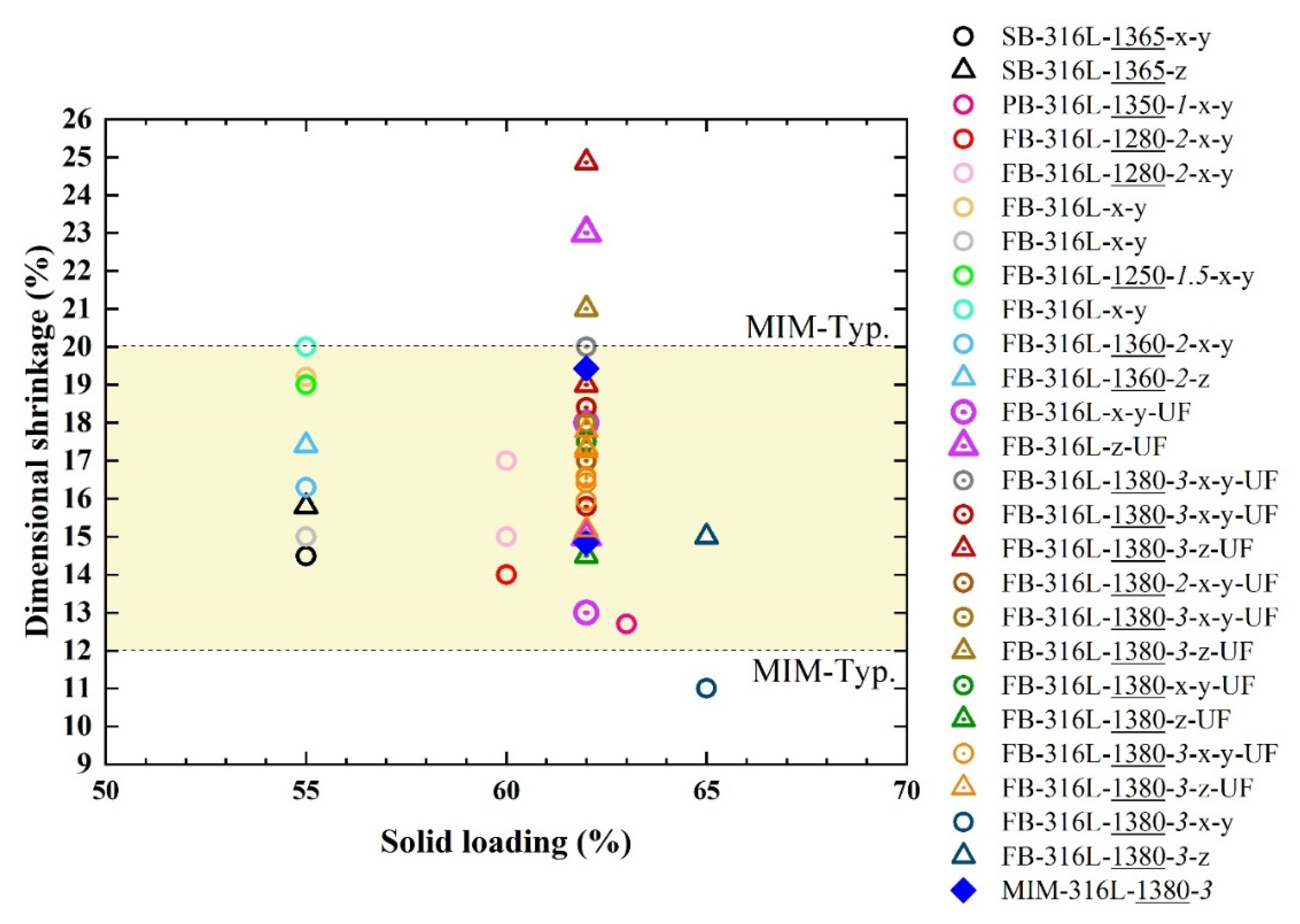
3.1. Effects of Solid Loading of Metal MEX Feedstock on the Shrinkage
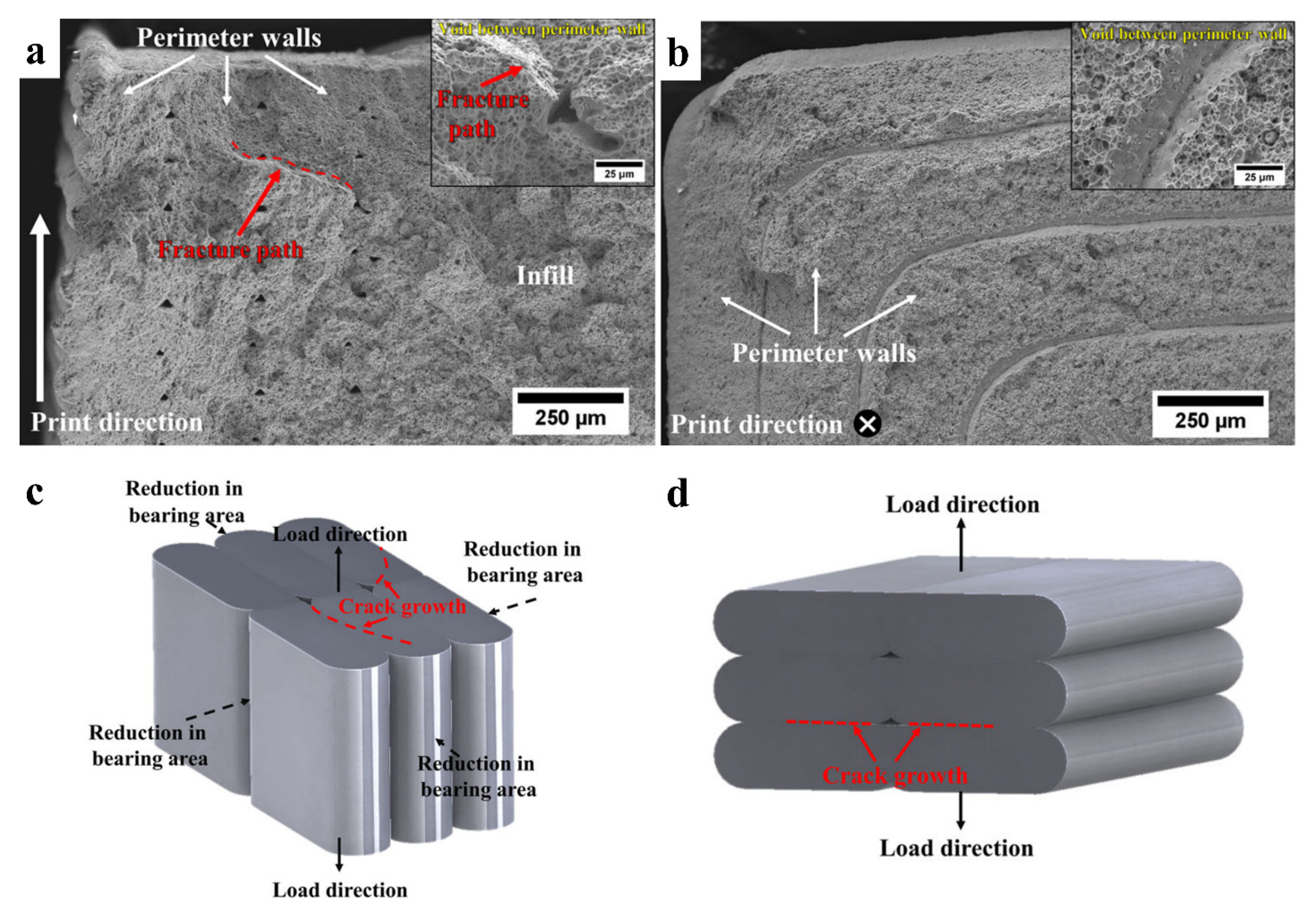
3.2. Effects of Printing Parameters on Physical and Mechanical Properties
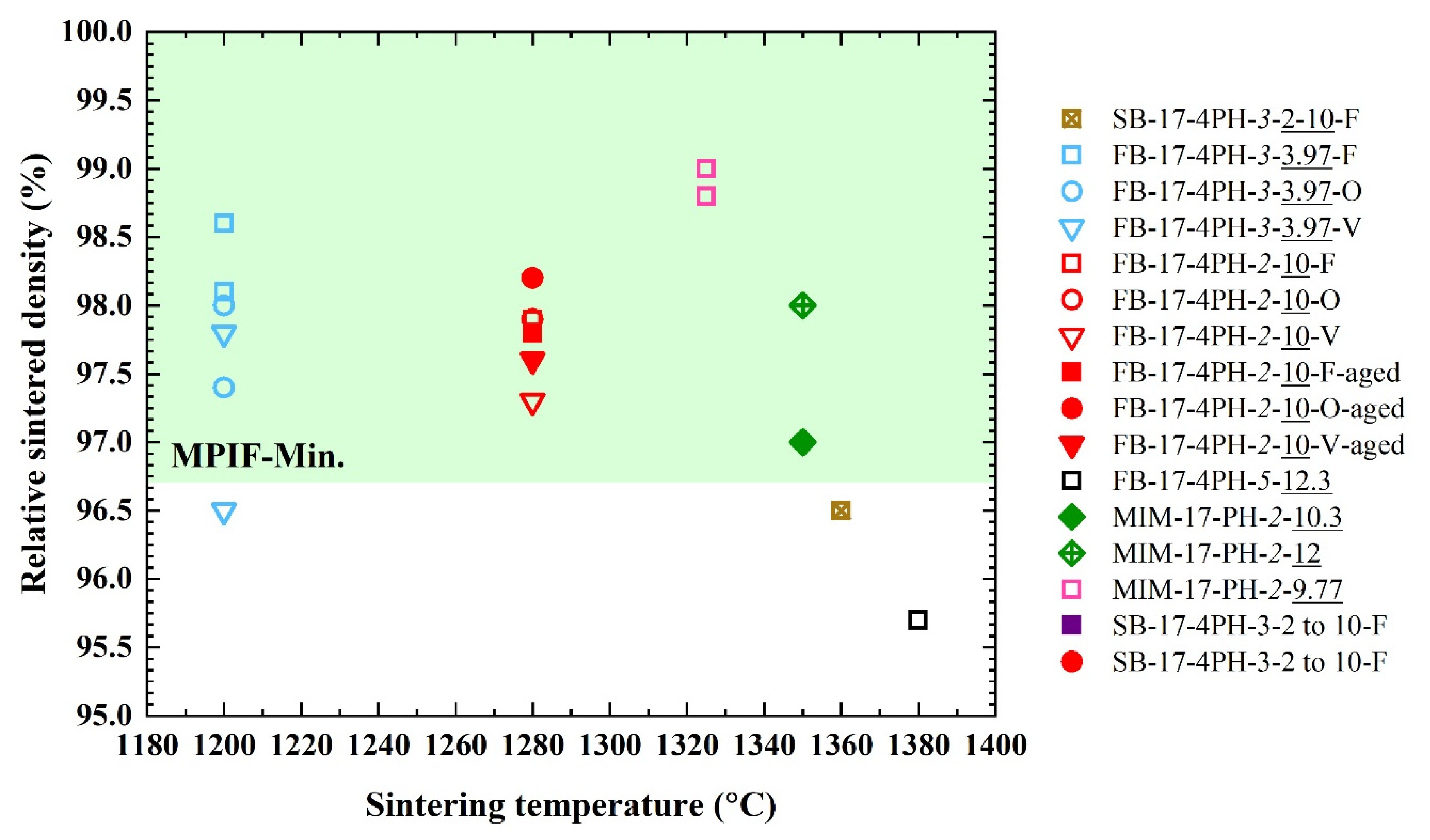
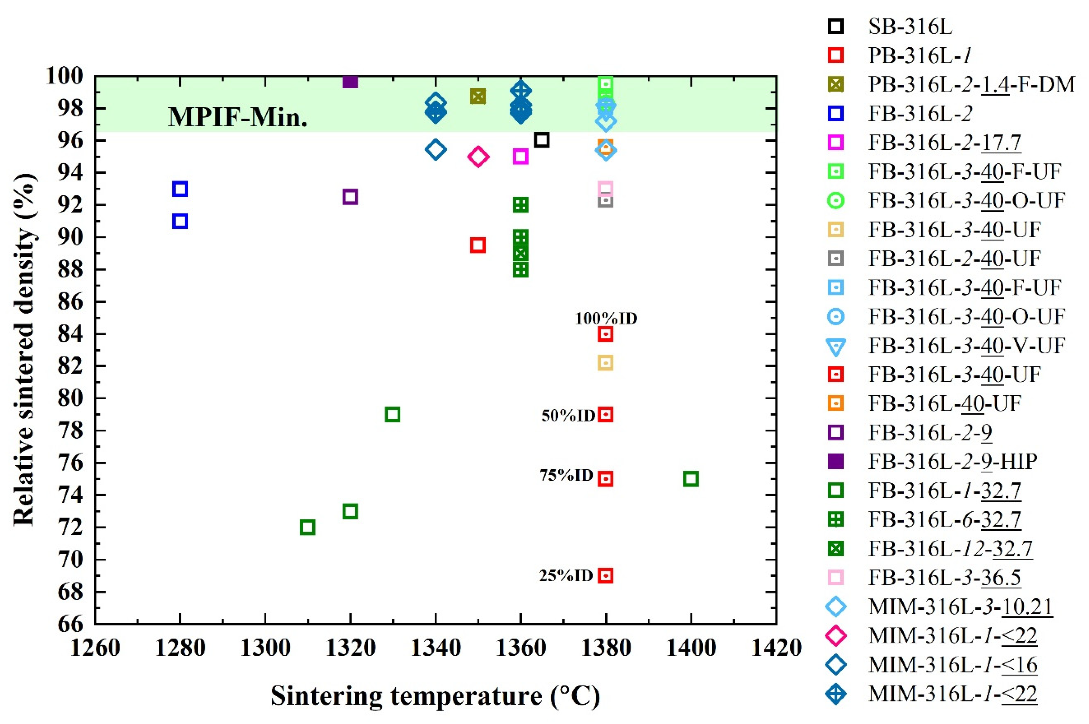
3.3. Effects of Sintering Conditions on the Relative Sintered Density of Alloys Compared to MIM
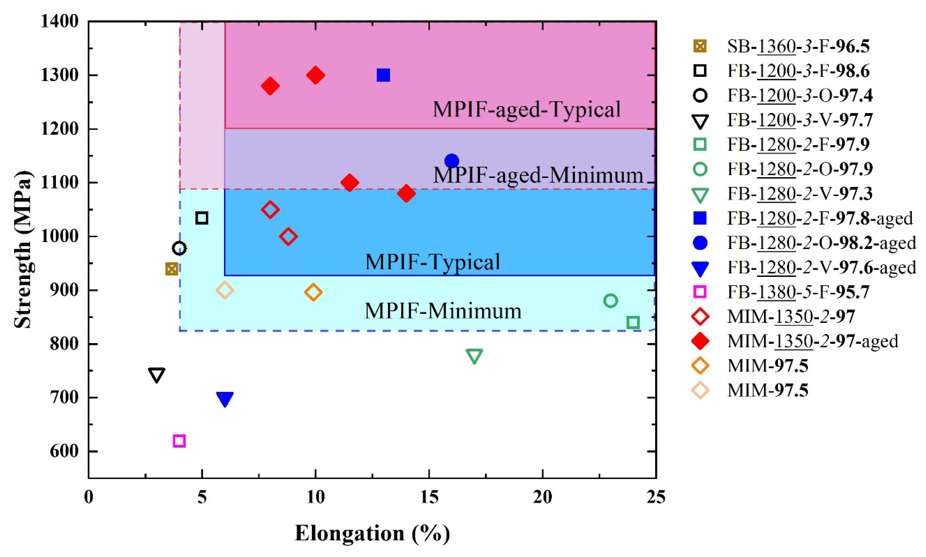
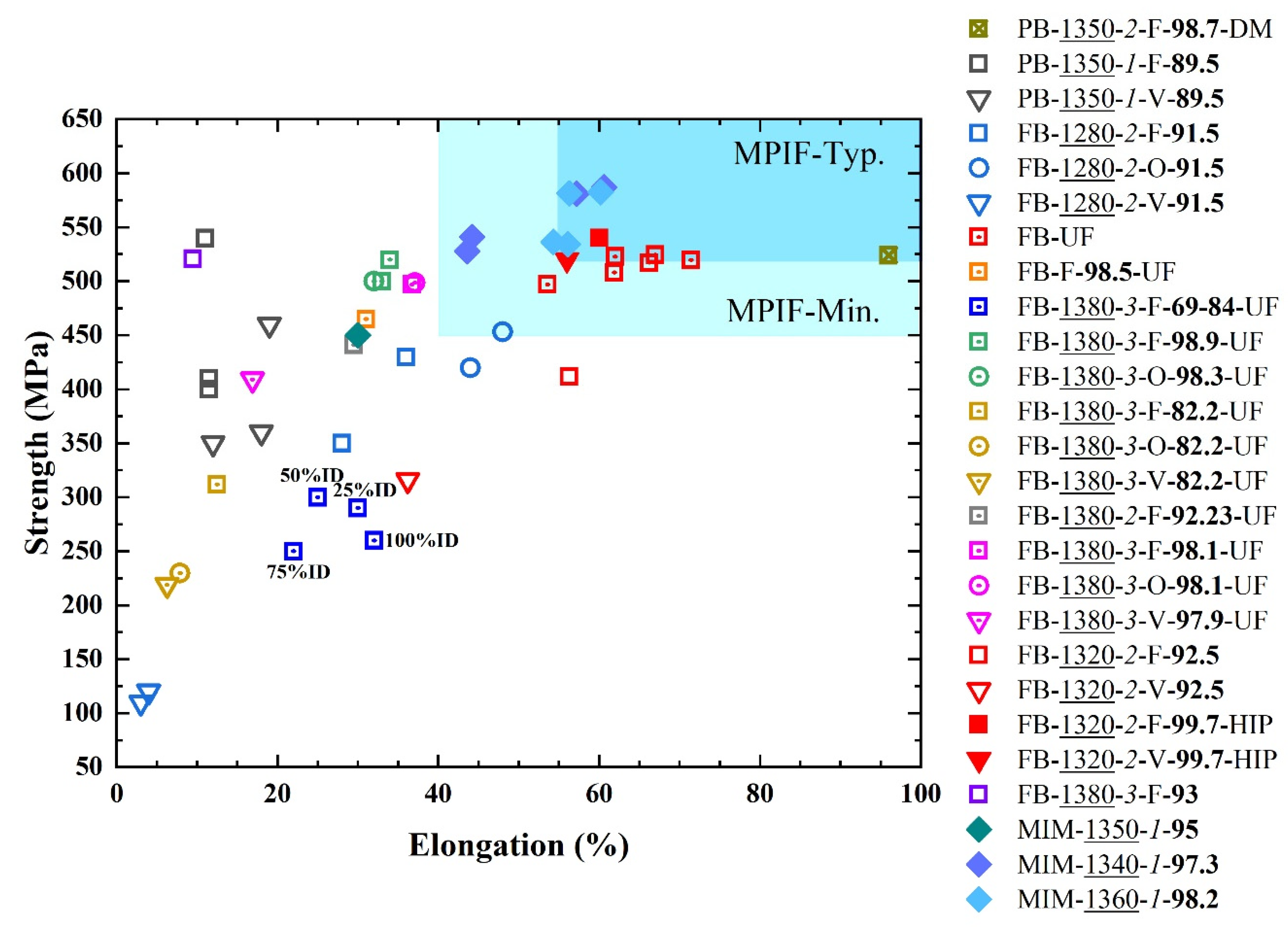
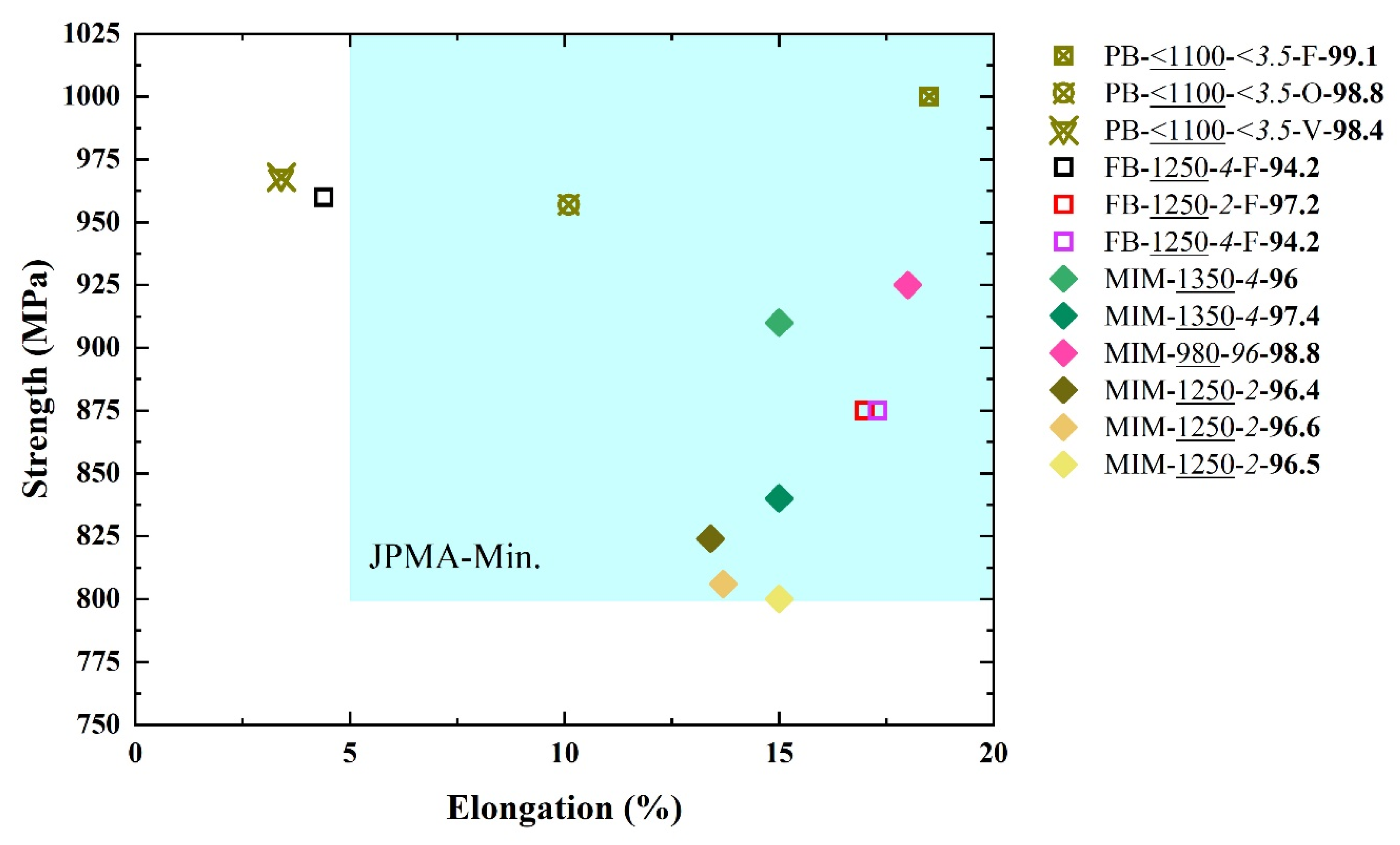
3.4. Tensile Properties Evaluation
4. Special Processes to Improve the Properties
5. Current, Prospective Applications and Future Direction of Metal MEX Development
6. Summary
Author Contributions
Funding
Institutional Review Board Statement
Informed Consent Statement
Data Availability Statement
Acknowledgments
Conflicts of Interest
References
- ISO/ASTM 52900:2021; Standard Terminology for Additive Manufacturing—General Principles—Terminology. ASTM International: West Conshohocken, PA, USA, 2021.
- Ngo, T.D.; Kashani, A.; Imbalzano, G.; Nguyen, K.T.Q.; Hui, D. Additive manufacturing (3D printing): A review of materials, methods, applications and challenges. Compos. Part B Eng. 2018, 143, 172–196. [Google Scholar] [CrossRef]
- Frazier, W.E. Metal additive manufacturing: A review. J. Mater. Eng. Perform. 2014, 23, 1917–1928. [Google Scholar] [CrossRef]
- Gonzalez-Gutierrez, J.; Cano, S.; Schuschnigg, S.; Kukla, C.; Sapkota, J.; Holzer, C. Additive manufacturing of metallic and ceramic components by the material extrusion of highly-filled polymers: A review and future perspectives. Materials 2018, 11, 840. [Google Scholar] [CrossRef] [PubMed] [Green Version]
- Nurhudan, A.I.; Supriadi, S.; Whulanza, Y.; Saragih, A.S. Additive manufacturing of metallic based on extrusion process: A review. J. Manuf. Processes 2021, 66, 228–237. [Google Scholar] [CrossRef]
- Suryawanshi, J.; Prashanth, K.G.; Ramamurty, U. Mechanical behavior of selective laser melted 316L stainless steel. Mater. Sci. Eng. A 2017, 696, 113–121. [Google Scholar] [CrossRef]
- Murr, L.E.; Martinez, E.; Hernandez, J.; Collins, S.; Amato, K.N.; Gaytan, S.M.; Shindo, P.W. Microstructures and properties of 17-4 PH stainless steel fabricated by Selective Laser Melting. J. Mater. Res. Technol. 2012, 1, 167–177. [Google Scholar] [CrossRef] [Green Version]
- Suwanpreecha, C.; Seensattayawong, P.; Vadhanakovint, V.; Manonukul, A. Influence of specimen layout on 17-4PH (AISI 630) alloys fabricated by low-cost additive manufacturing. Metall. Mater. Trans. A 2021, 52, 1999–2009. [Google Scholar] [CrossRef]
- Gong, H.; Snelling, D.; Kardel, K.; Carrano, A. Comparison of stainless steel 316L parts made by FDM- and SLM-based additive manufacturing processes. JOM 2019, 71, 880–885. [Google Scholar] [CrossRef]
- Barba, D.; Alabort, C.; Tang, Y.T.; Viscasillas, M.J.; Reed, R.C.; Alabort, E. On the size and orientation effect in additive manufactured Ti-6Al-4V. Mater. Des. 2020, 186, 108235. [Google Scholar] [CrossRef]
- Suwanpreecha, C.; Alabort, E.; Tang, Y.T.; Panwisawas, C.; Reed, R.C.; Manonukul, A. A novel low-modulus titanium alloy for biomedical applications: A comparison between selective laser melting and metal injection moulding. Mater. Sci. Eng. A 2021, 812, 141081. [Google Scholar] [CrossRef]
- Brandl, E.; Palm, F.; Michailov, V.; Viehweger, B.; Leyens, C. Mechanical properties of additive manufactured titanium (Ti–6Al–4V) blocks deposited by a solid-state laser and wire. Mater. Des. 2011, 32, 4665–4675. [Google Scholar] [CrossRef]
- Song, B.; Kenel, C.; Dunand, D.C. 3D ink-extrusion printing and sintering of Ti, Ti-TiB and Ti-TiC microlattices. Addit. Manuf. 2020, 35, 101412. [Google Scholar] [CrossRef]
- Trosch, T.; Strößner, J.; Völkl, R.; Glatzel, U. Microstructure and mechanical properties of selective laser melted Inconel 718 compared to forging and casting. Mater. Lett. 2016, 164, 428–431. [Google Scholar] [CrossRef]
- Pleass, C.; Jothi, S. Influence of powder characteristics and additive manufacturing process parameters on the microstructure and mechanical behaviour of Inconel 625 fabricated by Selective Laser Melting. Addit. Manuf. 2018, 24, 419–431. [Google Scholar] [CrossRef]
- Smith, D.H.; Bicknell, J.; Jorgensen, L.; Patterson, B.M.; Cordes, N.L.; Tsukrov, I.; Knezevic, M. Microstructure and mechanical behavior of direct metal laser sintered Inconel alloy 718. Mater. Charact. 2016, 113, 1–9. [Google Scholar] [CrossRef]
- Pérez-Ruiz, J.D.; Marin, F.; Martínez, S.; Lamikiz, A.; Urbikain, G.; López de Lacalle, L.N. Stiffening near-net-shape functional parts of Inconel 718 LPBF considering material anisotropy and subsequent machining issues. Mech. Syst. Signal Process. 2022, 168, 108675. [Google Scholar] [CrossRef]
- Pérez-Ruiz, J.D.; de Lacalle, L.N.L.; Urbikain, G.; Pereira, O.; Martínez, S.; Bris, J. On the relationship between cutting forces and anisotropy features in the milling of LPBF Inconel 718 for near net shape parts. Int. J. Mach. Tools Manuf. 2021, 170, 103801. [Google Scholar] [CrossRef]
- Darvish, K.; Chen, Z.W.; Phan, M.A.L.; Pasang, T. Selective laser melting of Co-29Cr-6Mo alloy with laser power 180–360W: Cellular growth, intercellular spacing and the related thermal condition. Mater. Charact. 2018, 135, 183–191. [Google Scholar] [CrossRef]
- Cloots, M.; Kunze, K.; Uggowitzer, P.J.; Wegener, K. Microstructural characteristics of the nickel-based alloy IN738LC and the cobalt-based alloy Mar-M509 produced by selective laser melting. Mater. Sci. Eng. A 2016, 658, 68–76. [Google Scholar] [CrossRef]
- Glerum, J.A.; Kenel, C.; Sun, T.; Dunand, D.C. Synthesis of precipitation-strengthened Al-Sc, Al-Zr and Al-Sc-Zr alloys via selective laser melting of elemental powder blends. Addit. Manuf. 2020, 36, 101461. [Google Scholar] [CrossRef]
- Griffiths, S.; Rossell, M.D.; Croteau, J.; Vo, N.Q.; Dunand, D.C.; Leinenbach, C. Effect of laser rescanning on the grain microstructure of a selective laser melted Al-Mg-Zr alloy. Mater. Charact. 2018, 143, 34–42. [Google Scholar] [CrossRef]
- Olakanmi, E.O. Selective laser sintering/melting (SLS/SLM) of pure Al, Al–Mg, and Al–Si powders: Effect of processing conditions and powder properties. J. Mater. Process. Technol. 2013, 213, 1387–1405. [Google Scholar] [CrossRef]
- Martin, J.H.; Yahata, B.D.; Hundley, J.M.; Mayer, J.A.; Schaedler, T.A.; Pollock, T.M. 3D printing of high-strength aluminium alloys. Nature 2017, 549, 365–369. [Google Scholar] [CrossRef]
- Michi, R.A.; Plotkowski, A.; Shyam, A.; Dehoff, R.R.; Babu, S.S. Towards high-temperature applications of aluminium alloys enabled by additive manufacturing. Int. Mater. Rev. 2021; 1–48, ahead-of-print. [Google Scholar] [CrossRef]
- Khorasani, M.; Ghasemi, A.; Rolfe, B.; Gibson, I. Additive manufacturing a powerful tool for the aerospace industry. Rapid Prototyp. J. 2021, 28, 87–100. [Google Scholar] [CrossRef]
- Caffrey, T.; Wohlers, T.; Campbell, I. Executive Summary of the Wohlers Report 2016; Loughborough University: Loughborough, UK, 2016. [Google Scholar]
- Buchanan, C.; Gardner, L. Metal 3D printing in construction: A review of methods, research, applications, opportunities and challenges. Eng. Struct. 2019, 180, 332–348. [Google Scholar] [CrossRef]
- Riecker, S.; Clouse, J.; Studnitzky, T.; Andersen, O.; Kieback, B. Fused Deposition Modeling-Opportunities for Cheap Metal AM. In Proceedings of the World PM2016 Congress & Exhibition, Hamburg, Germany, 9–13 October 2016. [Google Scholar]
- Rane, K.; Strano, M. A comprehensive review of extrusion-based additive manufacturing processes for rapid production of metallic and ceramic parts. Adv. Manuf. 2019, 7, 155–173. [Google Scholar] [CrossRef]
- Agarwala, M.; van Weeren, R.; Bandyopadhyay, A.; Safari, A.; Danforth, S.; Priedeman, W. Filament feed materials for fused deposition processing of ceramics and metals. In International Solid Freeform Fabrication Symposium Proceedings; University of Texas: Austin, TX, USA, 1996. [Google Scholar]
- Agarwala, M.; van Weeren, R.; Bandyopadhyay, A.; Whalen, P.; Safari, A.; Danforth, S. Fused deposition of ceramics and metals: An overview. In International Solid Freeform Fabrication Symposium Proceedings; University of Texas: Austin, TX, USA, 1996. [Google Scholar]
- Wu, G.; Langrana, N.A.; Rangarajan, S.; McCuiston, R.; Sadanji, R.; Danforth, S.; Safari, A. Fabrication of metal components using FDMet: Fused deposition of metals. In International Solid Freeform Fabrication Symposium Proceedings; University of Texas: Austin, TX, USA, 1996. [Google Scholar]
- Wu, G.; Langrana, N.A.; Sadanji, R.; Danforth, S. Solid freeform fabrication of metal components using fused deposition of metals. Mater. Des. 2002, 23, 97–105. [Google Scholar] [CrossRef]
- Burkhardt, C.; Freigassner, P.; Weber, O.; Imgrund, P.; Hampel, S. Fused filament fabrication (FFF) of 316L green parts for the MIM process. In Proceedings of the World PM2016 Congress & Exhibition, Hamburg, Germany, 9–13 October 2016. [Google Scholar]
- Giberti, H.; Strano, M.; Annoni, M. An innovative machine for Fused Deposition Modeling of metals and advanced ceramics. In MATEC Web of Conferences; EDP Sciences: Les Ulis, France, 2016; Volume 43, p. 03003. [Google Scholar]
- Kukla, C.; Duretek, I.; Schuschnigg, S.; Gonzalez-Gutierrez, J.; Holzer, C. Properties for PIM feedstocks used in fused filament fabrication. In Proceedings of the World PM2016 Congress & Exhibition, Hamburg, Germany, 9–13 October 2016. [Google Scholar]
- Gonzalez-Gutierrez, J.; Godec, D.; Kukla, C.; Schlauf, T.; Burkhardt, C.; Holzer, C. Shaping, debinding and sintering of steel components via fused filament fabrication. In Proceedings of the 16th International Scientific Conference on Production Engineering CIM 2017, Zadar, Croatia, 8–10 June 2017. [Google Scholar]
- Kukla, C.; Gonzalez-Gutierrez, J.; Cano, S.; Hampel, S.; Burkhardt, C.; Moritz, T.; Holzer, C. Fused filament fabricaton (FFF) of PIM feedstocks. In Proceedings of the VI Congreso Nacional de Pulvimetalurgia y I Congreso Iberoamericano de Conference, Ciudad Real, Spain, 7–9 June 2017. [Google Scholar]
- Kukla, C.; Gonzalez-Gutierrez, J.; Duretek, I.; Schuschnigg, S.; Holzer, C. Effect of particle size on the properties of highly-filled polymers for fused filament fabrication. In AIP Conference Proceedings; AIP Publishing: New York, NY, USA, 2017; Volume 1914, p. 190006. [Google Scholar]
- Lieberwirth, C.; Harder, A.; Seitz, H. Extrusion based additive manufacturing of metal parts. J. Mech. Eng. Autom. 2017, 7, 79–83. [Google Scholar]
- Condruz, M.R.; Paraschiv, A.; Puscasu, C. Heat treatment influence on hardness and microstructure of ADAM manufactured 17-4 PH. Turbo 2018, 5, 39–45. [Google Scholar]
- Gonzalez-Gutierez, J.; Godec, D.; Guráň, R.; Spoerk, M.; Kukla, C.; Holzer, C. 3D printing conditions determination for feedstock used in fused filament fabrication (FFF) of 17-4PH stainless steel parts. Metalurgija 2018, 57, 117–120. [Google Scholar]
- Gonzalez-Gutierrez, J.; Cano, S.; Schuschnigg, S.; Holzer, C.; Kukla, C. Highly-filled polymers for fused filament fabrication. Leobener Kunstst.-Kolloqu. 2018, 27, 93–104. [Google Scholar]
- Damon, J.; Dietrich, S.; Gorantla, S.; Popp, U.; Okolo, B.; Schulze, V. Process porosity and mechanical performance of fused filament fabricated 316L stainless steel. Rapid Prototyp. J. 2019, 25, 1319–1327. [Google Scholar] [CrossRef]
- Fidan, S.T.I. Dimensional analysis of metal powder infused filament-low cost metal 3D printing. In International Solid Freeform Fabrication Symposium Proceedings; University of Texas: Austin, TX, USA, 2019; pp. 533–541. [Google Scholar] [CrossRef]
- Galati, M.; Minetola, P. Analysis of density, roughness, and accuracy of the Atomic Diffusion Additive Manufacturing (ADAM) process for metal parts. Materials 2019, 12, 4122. [Google Scholar] [CrossRef] [PubMed] [Green Version]
- Gante Lokesha Renukaradhya, K. Metal Filament 3D Printing of SS316L: Focusing on the Printing Process. Master Thesis’s, KTH Royal Institute of Technology, Stockholm, Sweden, 2019. [Google Scholar]
- Gonzalez-Gutierrez, J.; Arbeiter, F.; Schlauf, T.; Kukla, C.; Holzer, C. Tensile properties of sintered 17-4PH stainless steel fabricated by material extrusion additive manufacturing. Mater. Lett. 2019, 248, 165–168. [Google Scholar] [CrossRef]
- Lengauer, W.; Duretek, I.; Fürst, M.; Schwarz, V.; Gonzalez-Gutierrez, J.; Schuschnigg, S.; Kukla, C.; Kitzmantel, M.; Neubauer, E.; Lieberwirth, C.; et al. Fabrication and properties of extrusion-based 3D-printed hardmetal and cermet components. Int. J. Refract. Met. Hard Mater. 2019, 82, 141–149. [Google Scholar] [CrossRef]
- Terry, S.M. Innovating the Fused Filament Fabrication Process Metal Powder Polylactic Acid Printing; Tennessee Technological University: Cookeville, TN, USA, 2019. [Google Scholar]
- Thompson, Y.; Gonzalez-Gutierrez, J.; Kukla, C.; Felfer, P. Fused filament fabrication, debinding and sintering as a low cost additive manufacturing method of 316L stainless steel. Addit. Manuf. 2019, 30, 100861. [Google Scholar] [CrossRef]
- Ait-Mansour, I.; Kretzschmar, N.; Chekurov, S.; Salmi, M.; Rech, J. Design-dependent shrinkage compensation modeling and mechanical property targeting of metal FFF. Prog. Addit. Manuf. 2020, 5, 51–57. [Google Scholar] [CrossRef] [Green Version]
- Godec, D.; Cano, S.; Holzer, C.; Gonzalez-Gutierrez, J. Optimization of the 3D printing parameters for tensile properties of specimens produced by Fused Filament Fabrication of 17-4PH stainless steel. Materials 2020, 13, 774. [Google Scholar] [CrossRef] [Green Version]
- Korotchenko, A.; Khilkov, D.; Tverskoy, M.; Khilkova, A. Use of additive technologies for metal injection molding. Eng. Solid Mech. 2020, 8, 143–150. [Google Scholar] [CrossRef]
- Kurose, T.; Abe, Y.; Santos, M.V.; Kanaya, Y.; Ishigami, A.; Tanaka, S.; Ito, H. Influence of the layer directions on the properties of 316L stainless steel parts fabricated through fused deposition of metals. Materials 2020, 13, 2493. [Google Scholar] [CrossRef] [PubMed]
- Liu, B.; Wang, Y.; Lin, Z.; Zhang, T. Creating metal parts by Fused Deposition Modeling and sintering. Mater. Lett. 2020, 263, 127252. [Google Scholar] [CrossRef]
- Niemelä, M. Experimental Strength Tests with Metal X. Bachelor’s Thesis, Vaasan Ammattikorkeakoulu University of Applied Sciences, Vaasa, Finland, 2020. [Google Scholar]
- Singh, P.; Balla, V.K.; Tofangchi, A.; Atre, S.V.; Kate, K.H. Printability studies of Ti-6Al-4V by metal fused filament fabrication (MF3). Int. J. Refract. Met. Hard Mater. 2020, 91, 105249. [Google Scholar] [CrossRef]
- Singh, P.; Shaikh, Q.; Balla, V.K.; Atre, S.V.; Kate, K.H. Estimating powder-polymer material properties used in design for Metal Fused Filament Fabrication (DfMF 3). JOM 2020, 72, 485–495. [Google Scholar] [CrossRef]
- Waalkes, L.; Längerich, J.; Holbe, F.; Emmelmann, C. Feasibility study on piston-based feedstock fabrication with Ti-6Al-4 V metal injection molding feedstock. Addit. Manuf. 2020, 35, 101207. [Google Scholar] [CrossRef]
- Watson, A.; Belding, J.; Ellis, B.D. Characterization of 17-4 PH Processed via Bound Metal Deposition (BMD); Springer International Publishing: Cham, Switzerland, 2020. [Google Scholar] [CrossRef]
- Zhang, Y.; Bai, S.; Riede, M.; Garratt, E.; Roch, A. A comprehensive study on Fused Filament Fabrication of Ti-6Al-4V structures. Addit. Manuf. 2020, 34, 101256. [Google Scholar] [CrossRef]
- Abe, Y.; Kurose, T.; Santos, M.V.; Kanaya, Y.; Ishigami, A.; Tanaka, S.; Ito, H. Effect of layer directions on internal structures and tensile properties of 17-4PH stainless steel parts fabricated by Fused Deposition of metals. Materials 2021, 14, 243. [Google Scholar] [CrossRef]
- Alkindi, T.; Alyammahi, M.; Susantyoko, R.A.; Atatreh, S. The effect of varying specimens’ printing angles to the bed surface on the tensile strength of 3D-printed 17-4PH stainless-steels via metal FFF additive manufacturing. MRS Commun. 2021, 11, 1–7. [Google Scholar] [CrossRef]
- Caminero, M.Á.; Romero, A.; Chacón, J.M.; Núñez, P.J.; García-Plaza, E.; Rodríguez, G.P. Additive manufacturing of 316L stainless-steel structures using fused filament fabrication technology: Mechanical and geometric properties. Rapid Prototyp. J. 2021, 27, 583–591. [Google Scholar] [CrossRef]
- Costa, J.; Sequeiros, E.; Vieira, M.T.; Vieira, M. Additive manufacturing: Material extrusion of metallic parts. J. Eng. 2021, 7, 53–69. [Google Scholar] [CrossRef]
- Hassan, W.; Farid, M.A.; Tosi, A.; Rane, K.; Strano, M. The effect of printing parameters on sintered properties of extrusion-based additively manufactured stainless steel 316L parts. Int. J. Adv. Manuf. Technol. 2021, 114, 3057–3067. [Google Scholar] [CrossRef]
- Henry, T.C.; Morales, M.A.; Cole, D.P.; Shumeyko, C.M.; Riddick, J.C. Mechanical behavior of 17-4 PH stainless steel processed by atomic diffusion additive manufacturing. Int. J. Adv. Manuf. Technol. 2021, 114, 2103–2114. [Google Scholar] [CrossRef]
- Jiang, D.; Ning, F. Additive manufacturing of 316L stainless steel by a printing-debinding-sintering method: Effects of microstructure on fatigue property. J. Manuf. Sci. Eng. 2021, 143, 1–30. [Google Scholar] [CrossRef]
- Mashekov, S.; Bazarbay, B.; Zhankeldi, A.; Mashekova, A. Development of technological basis of 3D printing with highly filled metal-poly-dimensional compositions for manufacture of metal products of complex shape. Metalurgija 2021, 60, 355–358. [Google Scholar]
- Mousapour, M.; Salmi, M.; Klemettinen, L.; Partanen, J. Feasibility study of producing multi-metal parts by Fused Filament Fabrication (FFF) technique. J. Manuf. Processes 2021, 67, 438–446. [Google Scholar] [CrossRef]
- Quarto, M.; Carminati, M.; D’Urso, G. Density and shrinkage evaluation of AISI 316L parts printed via FDM process. Mater. Manuf. Processes 2021, 36, 1535–1543. [Google Scholar] [CrossRef]
- Quarto, M.; Carminati, M.; D’Urso, G.; Giardini, C.; Maccarini, G. Processability of metal-filament through polymer FDM machine. In Proceedings of the 24th International Conference on Material Forming, Liège, Belgium, 14–16 April 2021. [Google Scholar] [CrossRef]
- Sadaf, M.; Bragaglia, M.; Nanni, F. A simple route for additive manufacturing of 316L stainless steel via Fused Filament Fabrication. J. Manuf. Processes 2021, 67, 141–150. [Google Scholar] [CrossRef]
- Shaikh, M.Q.; Lavertu, P.-Y.; Kate, K.H.; Atre, S.V. Process sensitivity and significant parameters investigation in Metal Fused Filament Fabrication of Ti-6Al-4V. J. Mater. Eng. Perform. 2021, 30, 5118–5134. [Google Scholar] [CrossRef]
- Shaikh, M.Q.; Singh, P.; Kate, K.H.; Freese, M.; Atre, S.V. Finite element-based simulation of metal fused filament fabrication process: Distortion Prediction and Experimental Verification. J. Mater. Eng. Perform. 2021, 30, 5135–5149. [Google Scholar] [CrossRef]
- Singh, P.; Balla, V.K.; Atre, S.V.; German, R.M.; Kate, K.H. Factors affecting properties of Ti-6Al-4V alloy additive manufactured by metal fused filament fabrication. Powder Technol. 2021, 386, 9–19. [Google Scholar] [CrossRef]
- Singh, P.; Balla, V.K.; Gokce, A.; Atre, S.V.; Kate, K.H. Additive manufacturing of Ti-6Al-4V alloy by metal fused filament fabrication (MF3): Producing parts comparable to that of metal injection molding. Prog. Addit. Manuf. 2021, 6, 593–606. [Google Scholar] [CrossRef]
- Tosto, C.; Tirillò, J.; Sarasini, F.; Cicala, G. Hybrid metal/polymer filaments for Fused Filament Fabrication (FFF) to print metal parts. Appl. Sci. 2021, 11, 1444. [Google Scholar] [CrossRef]
- Wang, Y.; Zhang, L.; Li, X.; Yan, Z. On hot isostatic pressing sintering of fused filament fabricated 316L stainless steel—Evaluation of microstructure, porosity, and tensile properties. Mater. Lett. 2021, 296, 129854. [Google Scholar] [CrossRef]
- Lu, Z.; Ayeni, O.I.; Yang, X.; Park, H.-Y.; Jung, Y.-G.; Zhang, J. Microstructure and phase analysis of 3d-printed components using bronze metal filament. J. Mater. Eng. Perform. 2020, 29, 1650–1656. [Google Scholar] [CrossRef]
- Cerejo, F.; Gatões, D.; Vieira, M. Optimization of metallic powder filaments for additive manufacturing extrusion (MEX). Int. J. Adv. Manuf. Technol. 2021, 115, 2449–2464. [Google Scholar] [CrossRef]
- Singh, G.; Missiaen, J.-M.; Bouvard, D.; Chaix, J.-M. Copper extrusion 3D printing using metal injection moulding feedstock: Analysis of process parameters for green density and surface roughness optimization. Addit. Manuf. 2021, 38, 101778. [Google Scholar] [CrossRef]
- Singh, G.; Missiaen, J.-M.; Bouvard, D.; Chaix, J.-M. Copper additive manufacturing using MIM feedstock: Adjustment of printing, debinding, and sintering parameters for processing dense and defectless parts. Int. J. Adv. Manuf. Technol. 2021, 115, 449–462. [Google Scholar] [CrossRef]
- Santos, C.; Gatões, D.; Cerejo, F.; Vieira, T. Influence of metallic powder characteristics on extruded feedstock performance for indirect additive manufacturing. Materials 2021, 14, 7136. [Google Scholar] [CrossRef]
- Vishwanath, A.; Rane, K.; Schaper, J.; Strano, M.; Casati, R. Rapid production of AZ91 Mg alloy by extrusion based additive manufacturing process. Powder Metall. 2021, 64, 370–377. [Google Scholar] [CrossRef]
- Shaikh, M.Q.; Graziosi, S.; Atre, S.V. Supportless printing of lattice structures by metal fused filament fabrication (MF3) of Ti-6Al-4V: Design and analysis. Rapid Prototyp. J. 2021, 27, 1408–1422. [Google Scholar] [CrossRef]
- Terry, S.; Fidan, I.; Tantawi, K. Preliminary investigation into metal-material extrusion. Prog. Addit. Manuf. 2021, 6, 133–141. [Google Scholar] [CrossRef]
- Gonzalez-Gutierrez, J.; Cano, S.; Ecker, J.V.; Kitzmantel, M.; Arbeiter, F.; Kukla, C.; Holzer, C. Bending properties of lightweight copper specimens with different infill patterns produced by material extrusion additive manufacturing, solvent debinding and sintering. Appl. Sci. 2021, 11, 7262. [Google Scholar] [CrossRef]
- Gloeckle, C.; Konkol, T.; Jacobs, O.; Limberg, W.; Ebel, T.; Handge, U.A. Processing of highly filled polymer–metal feedstocks for fused filament fabrication and the production of metallic implants. Materials 2020, 13, 4413. [Google Scholar] [CrossRef] [PubMed]
- Singh, G.; Missiaen, J.-M.; Bouvard, D.; Chaix, J.-M. Additive manufacturing of 17-4 PH steel using metal injection moulding feedstock: Analysis of 3D extrusion printing, debinding and sintering. Addit. Manuf. 2021, 47, 102287. [Google Scholar] [CrossRef]
- Moritzer, E.; Elsner, C.L.; Schumacher, C. Investigation of metal-polymer composites manufactured by fused deposition modeling with regard to process parameters. Polym. Compos. 2021, 42, 6065–6079. [Google Scholar] [CrossRef]
- Hasib, A.G.; Niauzorau, S.; Xu, W.; Niverty, S.; Kublik, N.; Williams, J.; Chawla, N.; Song, K.; Azeredo, B. Rheology scaling of spherical metal powders dispersed in thermoplastics and its correlation to the extrudability of filaments for 3D printing. Addit. Manuf. 2021, 41, 101967. [Google Scholar] [CrossRef]
- Shaikh, M.Q.; Nath, S.D.; Akilan, A.A.; Khanjar, S.; Balla, V.K.; Grant, G.T.; Atre, S.V. Investigation of patient-specific maxillofacial implant prototype development by metal fused filament fabrication (MF3) of Ti-6Al-4V. Dent. J. 2021, 9, 109. [Google Scholar] [CrossRef]
- Naranjo, J.A.; Berges, C.; Gallego, A.; Herranz, G. A novel printable high-speed steel filament: Towards the solution for wear-resistant customized tools by AM alternative. J. Mater. Res. Technol. 2021, 11, 1534–1547. [Google Scholar] [CrossRef]
- Dietrich, S.; Englert, L.; Pinter, P. Non-destructive characterization of additively manufactured components using X-Ray micro-computed tomography. In Solid Freeform Fabrication Symposium; University of Texas: Austin, TX, USA, 2018. [Google Scholar]
- Rosnitschek, T.; Seefeldt, A.; Alber-Laukant, B.; Neumeyer, T.; Altstädt, V.; Tremmel, S. Correlations of geometry and infill degree of extrusion additively manufactured 316L stainless steel components. Materials 2021, 14, 5173. [Google Scholar] [CrossRef] [PubMed]
- Mohammadizadeh, M.; Lu, H.; Fidan, I.; Tantawi, K.; Gupta, A.; Hasanov, S.; Zhang, Z.; Alifui-Segbaya, F.; Rennie, A. Mechanical and thermal analyses of Metal-PLA components fabricated by metal material extrusion. Inventions 2020, 5, 44. [Google Scholar] [CrossRef]
- Jimbo, K.; Tateno, T. Shape contraction in sintering of 3D objects fabricated via metal material extrusion in additive manufacturing. Int. J. Autom. Technol. 2019, 13, 354–360. [Google Scholar] [CrossRef]
- Zhang, Z.; Femi-Oyetoro, J.; Fidan, I.; Ismail, M.; Allen, M. Prediction of dimensional changes of low-cost metal material extrusion fabricated parts using machine learning techniques. Metals 2021, 11, 690. [Google Scholar] [CrossRef]
- Thompson, Y.; Polzer, M.; Gonzalez-Gutierrez, J.; Kasian, O.; Heckl, J.P.; Dalbauer, V.; Kukla, C.; Felfer, P.J. Fused filament fabrication-based additive manufacturing of commercially pure titanium. Adv. Eng. Mater. 2021, 23, 2100380. [Google Scholar] [CrossRef]
- Roshchupkin, S.; Golovin, V.; Kolesov, A.; Tarakhovskiy, A.Y. Extruder for the production of metal-polymer filament for additive technologies. In IOP Conference Series: Materials Science and Engineering; IOP Publishing: Bristol, UK, 2020; pp. 1–6. [Google Scholar]
- Obadimu, S.O.; McLaughlin, J.; Kourousis, K.I. Immersion ultrasonic testing of artificially induced defects in fused filament fabricated steel 316L. 3D Print. Addit. Manuf. 2021; in press. [Google Scholar] [CrossRef]
- Kan, X.; Yang, D.; Zhao, Z.; Sun, J. 316L FFF binder development and debinding optimization. Mater. Res. Express 2021, 8, 116515. [Google Scholar] [CrossRef]
- Wagner, M.A.; Hadian, A.; Sebastian, T.; Clemens, F.; Schweizer, T.; Rodriguez-Arbaizar, M.; Carreño-Morelli, E.; Spolenak, R. Fused filament fabrication of stainless steel structures—From binder development to sintered properties. Addit. Manuf. 2021, 49, 102472. [Google Scholar] [CrossRef]
- Jiang, D.; Ning, F. Anisotropic deformation of 316 L stainless steel overhang structures built by material extrusion based additive manufacturing. Addit. Manuf. 2021, 50, 102545. [Google Scholar] [CrossRef]
- Santamaria, R.; Salasi, M.; Bakhtiari, S.; Leadbeater, G.; Iannuzzi, M.; Quadir, M.Z. Microstructure and mechanical behaviour of 316L stainless steel produced using sinter-based extrusion additive manufacturing. J. Mater. Sci. 2022, 1–17. [Google Scholar] [CrossRef]
- Waalkes, L.; Längerich, J.; Imgrund, P.; Emmelmann, C. Piston-based material extrusion of Ti-6Al-4V feedstock for complementary use in metal injection molding. Materials 2022, 15, 351. [Google Scholar] [CrossRef]
- Suwanpreecha, C.; Manonukul, A. On the build orientation effect in as-printed and as-sintered bending properties of 17-4PH alloy fabricated by metal fused filament fabrication. Rapid Prototyp. J. 2022; in press. [Google Scholar] [CrossRef]
- Ramazani, H.; Kami, A. Metal FDM, a new extrusion-based additive manufacturing technology for manufacturing of metallic parts: A review. Prog. Addit. Manuf. 2022, 1–18. [Google Scholar] [CrossRef]
- Hong, S.; Sanchez, C.; Du, H.; Kim, N. Fabrication of 3D printed metal structures by use of high-viscosity cu paste and a screw extruder. J. Electron. Mater. 2015, 44, 836–841. [Google Scholar] [CrossRef]
- Yan, X.; Hao, L.; Xiong, W.; Tang, D. Research on influencing factors and its optimization of metal powder injection molding without mold via an innovative 3D printing method. RSC Adv. 2017, 7, 55232–55239. [Google Scholar] [CrossRef] [Green Version]
- Rane, K.; Di Landro, L.; Strano, M. Processability of SS316L powder—Binder mixtures for vertical extrusion and deposition on table tests. Powder Technol. 2019, 345, 553–562. [Google Scholar] [CrossRef]
- Rane, K.; Castelli, K.; Strano, M. Rapid surface quality assessment of green 3D printed metal-binder parts. J. Manuf. Processes 2019, 38, 290–297. [Google Scholar] [CrossRef]
- Ren, L.; Zhou, X.; Song, Z.; Zhao, C.; Liu, Q.; Xue, J.; Li, X. Process parameter optimization of extrusion-based 3D metal printing utilizing PW–LDPE–SA binder system. Materials 2017, 10, 305. [Google Scholar] [CrossRef] [PubMed] [Green Version]
- Annoni, M.; Giberti, H.; Strano, M. Feasibility study of an extrusion-based direct metal additive manufacturing technique. Procedia Manuf. 2016, 5, 916–927. [Google Scholar] [CrossRef] [Green Version]
- Rane, K.; Barriere, T.; Strano, M. Role of elongational viscosity of feedstock in extrusion-based additive manufacturing of powder-binder mixtures. Int. J. Adv. Manuf. Technol. 2020, 107, 4389–4402. [Google Scholar] [CrossRef]
- Mishra, A.A.; Momin, A.; Strano, M.; Rane, K. Implementation of viscosity and density models for improved numerical analysis of melt flow dynamics in the nozzle during extrusion-based additive manufacturing. Prog. Addit. Manuf. 2022, 7, 41–54. [Google Scholar] [CrossRef]
- Giberti, H.; Sbaglia, L.; Silvestri, M. Mechatronic design for an extrusion-based additive manufacturing machine. Machines 2017, 5, 29. [Google Scholar] [CrossRef] [Green Version]
- Parenti, P.; Cataldo, S.; Annoni, M. Shape deposition manufacturing of 316L parts via feedstock extrusion and green-state milling. Manuf. Lett. 2018, 18, 6–11. [Google Scholar] [CrossRef]
- Rosnitschek, T.; Glamsch, J.; Lange, C.; Alber-Laukant, B.; Rieg, F. An automated open-source approach for debinding simulation in metal extrusion additive manufacturing. Designs 2021, 5, 2. [Google Scholar] [CrossRef]
- Strano, M.; Rane, K.; Farid, M.A.; Mussi, V.; Zaragoza, V.; Monno, M. Extrusion-based additive manufacturing of forming and molding tools. Int. J. Adv. Manuf. Technol. 2021, 117, 2059–2071. [Google Scholar] [CrossRef]
- Ebel, T. 17—Metal injection molding (MIM) of titanium and titanium alloys. In Handbook of Metal Injection Molding; Heaney, D.F., Ed.; Woodhead Publishing: Sawston, UK, 2012; pp. 415–445. [Google Scholar] [CrossRef]
- Miura, H.; Osada, T.; Itoh, Y. Metal Injection Molding (Mim) Processing. In Advances in Metallic Biomaterials: Processing and Applications; Niinomi, M., Narushima, T., Nakai, M., Eds.; Springer: Berlin/Heidelberg, Germany, 2015; pp. 27–56. [Google Scholar] [CrossRef]
- Ebel, T. Titanium MIM for manufacturing of medical implants and devices. In Titanium in Medical and Dental Applications; Elsevier: Amsterdam, The Netherlands, 2018; pp. 531–551. [Google Scholar] [CrossRef]
- European Powder Metallurgy Association. Metal Injection Moulding: A Manufacturing Process for Precision Engineering Components; European Powder Metallurgy Association: Shrewsbury, UK, 2013. [Google Scholar]
- Popescu, D.; Zapciu, A.; Amza, C.; Baciu, F.; Marinescu, R. FDM process parameters influence over the mechanical properties of polymer specimens: A review. Polym. Test. 2018, 69, 157–166. [Google Scholar] [CrossRef]
- Samykano, M.; Selvamani, S.K.; Kadirgama, K.; Ngui, W.K.; Kanagaraj, G.; Sudhakar, K. Mechanical property of FDM printed ABS: Influence of printing parameters. Int. J. Adv. Manuf. Technol. 2019, 102, 2779–2796. [Google Scholar] [CrossRef]
- Wickramasinghe, S.; Do, T.; Tran, P. FDM-based 3D printing of polymer and associated composite: A review on mechanical properties, defects and treatments. Polymers 2020, 12, 1529. [Google Scholar] [CrossRef]
- Turner, B.N.; Strong, R.; Gold, S.A. A review of melt extrusion additive manufacturing processes: I. Process design and modeling. Rapid Prototyp. J. 2014, 20, 192–204. [Google Scholar] [CrossRef]
- Valkenaers, H.; Vogeler, F.; Ferraris, E.; Voet, A.; Kruth, J.-P. A novel approach to additive manufacturing: Screw extrusion 3D-printing. In Proceedings of the 10th International Conference on Multi-Material Micro Manufacture, San Sebastian, Spain, 8–10 October 2013; Research Publishing: Singapore. [CrossRef]
- Bellini, A.; Shor, L.; Guceri, S.I. New developments in fused deposition modeling of ceramics. Rapid Prototyp. J. 2005, 11, 214–220. [Google Scholar] [CrossRef]
- Manonukul, A.; Likityingwara, W.; Rungkiatnawin, P.; Muenya, N.; Amoranan, S.; Kittinantapol, W.; Surapunt, S. Study of recycled and virgin compounded metal injection moulded feedstock for stainless steel 630. J. Solid Mech. Mater. Eng. 2007, 1, 411–420. [Google Scholar] [CrossRef] [Green Version]
- AIM3D GmbH Edelstahl. The Next Generation of 3D Printing Advantages of the ExAM 255. Available online: https://www.aim3d.de/en/products/exam-255/ (accessed on 27 October 2021).
- Pollen, Ltd. PAM: Pellet Additive Manufacturing. Available online: https://www.pollen.am/ (accessed on 27 October 2021).
- Direct3D, Pellet Extrusion. Available online: https://www.direct3d.it/ (accessed on 27 October 2021).
- Desktop Metal, Inc. Prototype and Mass Produce with the Same Alloys. Available online: https://www.desktopmetal.com/products/materials/ (accessed on 27 October 2021).
- Masood, S.H. Advances in fused deposition modeling. In Comprehensive Materials Processing; Elsevier: Amsterdam, The Netherlands, 2014; pp. 69–91. [Google Scholar]
- Markforged, Inc. Complete Metal Solution. Available online: https://markforged.com/metal-x/ (accessed on 27 October 2021).
- Sargini, M.I.M.; Masood, S.H.; Palanisamy, S.; Jayamani, E.; Kapoor, A. Additive manufacturing of an automotive brake pedal by metal fused deposition modelling. Mater. Today Proc. 2021, 45, 4601–4605. [Google Scholar] [CrossRef]
- Chen, C.L.; Thomson, R.C. Study on thermal expansion of intermetallics in multicomponent Al–Si alloys by high temperature X-ray diffraction. Intermetallics 2010, 18, 1750–1757. [Google Scholar] [CrossRef]
- Turner, B.N.; Gold, S.A. A review of melt extrusion additive manufacturing processes: II. Materials, dimensional accuracy, and surface roughness. Rapid Prototyp. J. 2015, 21, 250–261. [Google Scholar] [CrossRef]
- Ian Gibson, I.G. Additive Manufacturing Technologies 3D Printing, Rapid Prototyping, and Direct Digital Manufacturing; Springer: Berlin/Heidelberg, Germany, 2015. [Google Scholar]
- Hwang, S.; Reyes, E.I.; Moon, K.-S.; Rumpf, R.C.; Kim, N.S. Thermo-mechanical characterization of metal/polymer composite filaments and printing parameter study for fused deposition modeling in the 3D printing process. J. Electron. Mater. 2015, 44, 771–777. [Google Scholar] [CrossRef]
- The Virtual Foundry, Printing Pure Metal with FILAMET™. Available online: https://www.thevirtualfoundry.com/help (accessed on 27 October 2021).
- Ultrafuse 316L. Available online: https://www.ultrafusefff.com/product-category/metal/ultrafuse-316l/ (accessed on 27 October 2021).
- 316L Metal Filament 1.75 mm. Available online: https://www.anycubic.com/products/316l-metal-filament-1-75mm316L (accessed on 27 October 2021).
- Heaney, D.F. Handbook of Metal Injection Molding; Woodhead Publishing: Sawston, UK, 2018. [Google Scholar]
- Ultrafuse 17-4PH. Available online: https://www.basf.com/global/de/who-we-are/organization/group-companies/BASF_New-Business-GmbH/news/press-releases/2020/201202-launch-ultrafuse.html (accessed on 3 February 2022).
- Dehghan-Manshadi, A.; StJohn, D.; Dargusch, M.; Chen, Y.; Sun, J.F.; Qian, M. Metal injection moulding of non-spherical titanium powders: Processing, microstructure and mechanical properties. J. Manuf. Processes 2018, 31, 416–423. [Google Scholar] [CrossRef]
- Wu, Y.; Wang, R.; Kwon, Y.-S.; Park, S.-J.; German, R.M. Injection molding of HDH titanium powder. Int. J. Powder Metall. 2006, 42, 59–66. [Google Scholar]
- Dehghan-Manshadi, A.; Bermingham, M.J.; Dargusch, M.S.; StJohn, D.H.; Qian, M. Metal injection moulding of titanium and titanium alloys: Challenges and recent development. Powder Technol. 2017, 319, 289–301. [Google Scholar] [CrossRef] [Green Version]
- Gulsoy, H.O.; Pazarlioglu, S.; Gulsoy, N.; Gundede, B.; Mutlu, O. Effect of Zr, Nb and Ti addition on injection molded 316L stainless steel for bio-applications: Mechanical, electrochemical and biocompatibility properties. J. Mech. Behav. Biomed. Mater. 2015, 51, 215–224. [Google Scholar] [CrossRef]
- Bidaux, J.-E.; Pasquier, R.; Rodriguez-Arbaizar, M.; Girard, H.; Carreño-Morelli, E. Low elastic modulus Ti–17Nb processed by powder injection moulding and post-sintering heat treatments. Powder Metall. 2014, 57, 320–323. [Google Scholar] [CrossRef]
- Davies, P.; Dunstan, R.; Howells, R.; Hayward, A. Development of master alloy powders, including nickel-based superalloys, for Metal Injection Molding (MIM). Adv. Powder Metall. Part. Mater. 2003.
- Wu, M.-W.; Huang, Z.-K.; Tseng, C.-F.; Hwang, K.-S. Microstructures, mechanical properties, and fracture behaviors of metal-injection molded 17-4PH stainless steel. Met. Mater. Int. 2015, 21, 531–537. [Google Scholar] [CrossRef]
- Manonukul, A.; Songkuea, S.; Moonchaleanporn, P.; Tange, M. Effect of weld line positions on the tensile deformation of two-component metal injection moulding. Int. J. Miner. Metall. Mater. 2017, 24, 1384–1393. [Google Scholar] [CrossRef]
- Huang, M.-S.; Hsu, H.-C. Effect of backbone polymer on properties of 316L stainless steel MIM compact. J. Mater. Processing Technol. 2009, 209, 5527–5535. [Google Scholar] [CrossRef]
- Castro, L.; Merino, S.; Levenfeld, B.; Várez, A.; Torralba, J.M. Mechanical properties and pitting corrosion behaviour of 316L stainless steel parts obtained by a modified metal injection moulding process. J. Mater. Processing Technol. 2003, 143–144, 397–402. [Google Scholar] [CrossRef]
- Heaney, D.; Mueller, T.; Davies, P. Mechanical properties of metal injection moulded 316L stainless steel using both prealloy and master alloy techniques. Powder Metall. 2004, 47, 367–373. [Google Scholar] [CrossRef]
- Froes, F.H. Getting better: Big boost for titanium MIM prospects. Met. Powder Rep. 2006, 61, 20–23. [Google Scholar] [CrossRef]
- Kudo, K.; Shinagawa, K.; Miura, H. Effect of α + β region sintering on the mechanical properties of injection molded Ti-6Al-4V compacts. Mech. Eng. J. 2018, 5, 17-00686. [Google Scholar] [CrossRef] [Green Version]
- Ferri, O.M.; Ebel, T.; Bormann, R. Influence of surface quality and porosity on fatigue behaviour of Ti–6Al–4V components processed by MIM. Mater. Sci. Eng. A 2010, 527, 1800–1805. [Google Scholar] [CrossRef] [Green Version]
- German, R. Progress in titanium metal powder injection molding. Materials 2013, 6, 3641–3662. [Google Scholar] [CrossRef]
- Wen, G.; Cao, P.; Gabbitas, B.; Zhang, D.; Edmonds, N. Development and design of binder systems for titanium metal injection molding: An overview. Metall. Mater. Trans. A 2013, 44, 1530–1547. [Google Scholar] [CrossRef] [Green Version]
- Rhee, B.O.; Chung, C. Effects of the binder characteristics on binder separation in powder injection molding. In Proceedings of the 1992 Powder Injection Molding Symposium, San Francisco, CA, USA, 21–26 June 1992. [Google Scholar]
- McNulty, T.F.; Mohammadi, F.; Bandyopadhyay, A.; Shanefield, D.; Danforth, S.; Safari, A. Development of a binder formulation for fused deposition of ceramics. Rapid Prototyp. J. 1998, 4, 144–150. [Google Scholar] [CrossRef] [Green Version]
- MPIF. Material Standards for Metal Injection Molded Parts; Metal Powder Industries Federation: Princeton, NJ, USA, 2016. [Google Scholar]
- Choe, J.; Osada, T.; Kudo, K.; Tsumori, F.; Miura, H. Effect of minor boron addition on the fatigue strength and high temperature properties of injection molded Ti-6Al-4V compacts. J. Jpn. Soc. Powder Powder Metall. 2016, 63, 451–456. [Google Scholar] [CrossRef] [Green Version]
- Ferri, O.M.; Ebel, T.; Bormann, R. High cycle fatigue behaviour of Ti–6Al–4V fabricated by metal injection moulding technology. Mater. Sci. Eng. A 2009, 504, 107–113. [Google Scholar] [CrossRef] [Green Version]
- ISO 22068:2012; Sintered-Metal Injection-Molded Materials—Specification. Japan Powder Metallurgy Association: Tokyo, Japan, 2014.
- Spoerk, M.; Gonzalez-Gutierrez, J.; Sapkota, J.; Schuschnigg, S.; Holzer, C. Effect of the printing bed temperature on the adhesion of parts produced by fused filament fabrication. Plast. Rubber Compos. 2018, 47, 17–24. [Google Scholar] [CrossRef]
- Singh, K. Experimental study to prevent the warping of 3D models in fused deposition modeling. Int. J. Plast. Technol. 2018, 22, 177–184. [Google Scholar] [CrossRef]
- Kankawa, Y. Metal Powder Injection Moldable Composition, and Injection Molding and Sintering Method Using Such Composition. U.S. Patent US6051184A, 2000. [Google Scholar]
- Kankawa, Y. Single step MIM system with polyacetal binder without debinding process. In Proceedings of the World PM2000 Congress & Exhibition, Kyoto, Japan, 12–16 November 2000; pp. 270–273. [Google Scholar]
- Desktop Metal, Inc. Studio System™ 2. Available online: https://www.desktopmetal.com/products/studio (accessed on 27 October 2021).
- Hamidi, M.F.F.A.; Harun, W.S.W.; Samykano, M.; Ghani, S.A.C.; Ghazalli, Z.; Ahmad, F.; Sulong, A.B. A review of biocompatible metal injection moulding process parameters for biomedical applications. Mater. Sci. Eng. C 2017, 78, 1263–1276. [Google Scholar] [CrossRef] [Green Version]
- Shibo, G.; Xuanhui, Q.; Xinbo, H.; Ting, Z.; Bohua, D. Powder injection molding of Ti–6Al–4V alloy. J. Mater. Process. Technol. 2006, 173, 310–314. [Google Scholar] [CrossRef]
- Chalermkarnnon, P.; Manonukul, A.; Muenya, N.; Nakayama, H.; Fujiwara, M. Minimizing contamination in commercial mass production of metal injection molded pure titanium. J. Manuf. Sci. Eng. 2011, 133, 054502. [Google Scholar] [CrossRef]
- Bootchai, S.; Taweejun, N.; Manonukul, A.; Kanchanomai, C. Metal injection molded titanium: Mechanical properties of debinded powder and sintered metal. J. Mater. Eng. Perform. 2020, 29, 4559–4568. [Google Scholar] [CrossRef]
- Ebel, T.; Blawert, C.; Willumeit, R.; Luthringer, B.J.; Ferri, O.M.; Feyerabend, F. Ti–6Al–4V–0.5 B—A modified alloy for implants produced by metal injection molding. Adv. Eng. Mater. 2011, 13, B440–B453. [Google Scholar] [CrossRef] [Green Version]
- Kafkas, F.; Ebel, T. Metallurgical and mechanical properties of Ti–24Nb–4Zr–8Sn alloy fabricated by metal injection molding. J. Alloys Compd. 2014, 617, 359–366. [Google Scholar] [CrossRef]
- German, R.M. Sintering Theory and Practice; John Wiley & Sons: New York, NY, USA, 1996. [Google Scholar]
- Annicchiarico, D.; Alcock, J.R. Review of factors that affect shrinkage of molded part in injection molding. Mater. Manuf. Processes 2014, 29, 662–682. [Google Scholar] [CrossRef]
- Itoh, Y.; Miura, H.; Uematsu, T.; Sato, K.; Niinomi, M.; Ozawa, T. The commercial potential of MIM titanium alloy. Met. Powder Rep. 2009, 64, 17–20. [Google Scholar] [CrossRef]
- Zhao, D.-p.; Ebel, T.; Yan, M.; Qian, M. Trace carbon in biomedical beta-titanium alloys: Recent progress. JOM 2015, 67, 2236–2243. [Google Scholar] [CrossRef]
- Yan, M.; Qian, M.; Kong, C.; Dargusch, M.S. Impacts of trace carbon on the microstructure of as-sintered biomedical Ti–15Mo alloy and reassessment of the maximum carbon limit. Acta Biomater. 2014, 10, 1014–1023. [Google Scholar] [CrossRef]
- Xu, P.; Pyczak, F.; Yan, M.; Limberg, W.; Willumeit-Römer, R.; Ebel, T. Tensile toughening of powder-injection-molded β Ti-Nb-Zr biomaterials by adjusting TiC particle distribution from aligned to dispersed pattern. Appl. Mater. Today 2020, 19, 100630. [Google Scholar] [CrossRef]
- Schaper, J.G.; Wolff, M.; Wiese, B.; Ebel, T.; Willumeit-Römer, R. Powder metal injection moulding and heat treatment of AZ81 Mg alloy. J. Mater. Process. Technol. 2019, 267, 241–246. [Google Scholar] [CrossRef]
- Olevsky, E.; German, R. Effect of gravity on dimensional change during sintering—I. Shrinkage anisotropy. Acta Mater. 2000, 48, 1153–1166. [Google Scholar] [CrossRef]
- Li, Y.; Li, L.; Khalil, K.A. Effect of powder loading on metal injection molding stainless steels. J. Mater. Process. Technol. 2007, 183, 432–439. [Google Scholar] [CrossRef]
- Akhoundi, B.; Behravesh, A.H. Effect of filling pattern on the tensile and flexural mechanical properties of FDM 3D printed products. Exp. Mech. 2019, 59, 883–897. [Google Scholar] [CrossRef]
- Pandzic, A.; Hodzic, D.; Milovanovic, A. Effect of infill type and density on tensile properties of PLA material for FDM process. Ann. DAAAM Proc. 2019, 545–554. [Google Scholar] [CrossRef]
- Srinivasan, R.; Nirmal Kumar, K.; Jenish Ibrahim, A.; Anandu, K.V.; Gurudhevan, R. Impact of fused deposition process parameter (infill pattern) on the strength of PETG part. Mater. Today Proc. 2020, 27, 1801–1805. [Google Scholar] [CrossRef]
- Kato, K. Effect of sintering temperature on density and tensile properties of titanium compacts by matal injection molding. J. Jpn. Soc. Powder Powder Metall. 1999, 46, 865–869. [Google Scholar] [CrossRef]
- Ye, H.; Liu, X.Y.; Hong, H. Sintering of 17-4PH stainless steel feedstock for metal injection molding. Mater. Lett. 2008, 62, 3334–3336. [Google Scholar] [CrossRef] [Green Version]
- Ji, C.H.; Loh, N.H.; Khor, K.A.; Tor, S.B. Sintering study of 316L stainless steel metal injection molding parts using Taguchi method: Final density. Mater. Sci. Eng. A 2001, 311, 74–82. [Google Scholar] [CrossRef]
- Wang, J.; Xie, H.; Wang, L.; Senthil, T.; Wang, R.; Zheng, Y.; Wu, L. Anti-gravitational 3D printing of polycaprolactone-bonded Nd-Fe-B based on fused deposition modeling. J. Alloys Compd. 2017, 715, 146–153. [Google Scholar] [CrossRef]
- Maidin, S.; Muhamad, M.; Pei, E. Feasibility study of ultrasonic frequency application on fdm to improve parts surface finish. J. Teknol. 2015, 77, 27–35. [Google Scholar] [CrossRef] [Green Version]
- Ravoori, D.; Salvi, S.; Prajapati, H.; Qasaimeh, M.; Adnan, A.; Jain, A. Void reduction in fused filament fabrication (FFF) through in situ nozzle-integrated compression rolling of deposited filaments. Virtual Phys. Prototyp. 2021, 16, 1–14. [Google Scholar] [CrossRef]
- Luo, X.; Ebel, T.; Pyczak, F.; Limberg, W.; Lin, Y. Carbide evolution and its potential reduction methods in Ti-22Nb based alloys prepared by metal injection moulding. Mater. Lett. 2017, 193, 295–298. [Google Scholar] [CrossRef]
- Kudo, K.; Ishimitsu, H.; Choe, J.; Osada, T.; Miura, H.; Shinagawa, K. Effect of grain size on the fatigue properties of injection moulded Ti-6Al-4V compacts. In Proceedings of the World PM2016 Congress & Exhibition, Hamburg, Germany, 9–13 October 2016. [Google Scholar]
- Kudo, K.; Ishimitsu, H.; Osada, T.; Tsumori, F.; Miura, H. Static and dynamic fracture characteristics of the MIM Ti-6Al-4V alloy compacts using fine powder. J. Jpn. Soc. Powder Powder Metall. 2016, 63, 445–450. [Google Scholar] [CrossRef] [Green Version]
- Ferri, O.M.; Ebel, T.; Bormann, R. The influence of a small boron addition on the microstructure and mechanical properties of Ti-6Al-4V fabricated by metal injection moulding. Adv. Eng. Mater. 2011, 13, 436–447. [Google Scholar] [CrossRef]
- Vieira Muterlle, P. Microstructural and Mechanical Properties of Co and Ti Alloys for Biomedical Applications Produced by Metal Injection Molding (MIM); University of Trento: Trento, Italy, 2010. [Google Scholar]
- Suwanpreecha, C.; Manonukul, A. Review: Fatigue properties of Ti-6Al-4V alloys fabricated by metal injection moulding. SIAM Sci. Innov. Adv. Mater. 2021, 1, 64005. [Google Scholar]


| Type of Printer | Printer Model | Ref. |
|---|---|---|
| Screw-based | 1. In-house built printers | [41,132] |
| 2. ExAM 255 printer | [50,84,85,92] | |
| Plunger-based | 1. In-house built printers | [36,61,68,87,109,113,114,115,116,117,118,119,120,121] |
| 2. Special purposed and closed metal printer | [62,108] | |
| • Desktop Metal Studio+ system | ||
| Filament-based | 1. General polymer FDM printers | |
| • 3D Modeler™ | [32] | |
| • Apium P155 | [45] | |
| • Apium P220 | [97] | |
| • Axiom Dual, Airwolf | [100] | |
| • Crane Quad 3D machine | [72] | |
| • Duplicator i3 v2 FFF | [38,43,44,49] | |
| • Flashforge Dreamer | [9] | |
| • Funmat HT | [53] | |
| • German RepRap X500 | [98] | |
| • German RepRap X1000 | [90] | |
| • HAGE 3Dp-A2 | [37,40] | |
| • Hephestos 2 | [106] | |
| • L-DEVO M2030TP | [56,64] | |
| • MakerBot Replicator 2 | [82] | |
| • Modified Hage 3D-72L | [35] | |
| • PrintBox3D | [71] | |
| • Prusa i3 Mk2 | [52,102] | |
| • Prusa i3 Mk3 | [48,54,83,86] | |
| • Prusa i3 Mk3s | [93] | |
| • Prusa Steel Black Edition Mark II | [96] | |
| • Pulse 3D from MatterHackers | [59,60,77,78,79,88,95] | |
| • Renkforce 1000 printer | [63] | |
| • Raised 3D pro2 | [99] | |
| • TAZ6 | [70,107] | |
| • Ultimaker 2 | [29,46,51,89] | |
| • Ultimaker 3 | [66,91,94] | |
| • Ultimaker S5 | [73,99,101] | |
| • WANHAO Duplicator 4S | [105] | |
| • Zmorph 2S | [75] | |
| • Zortrax M200 | [80] | |
| 2. Special purposed and close metal printer | ||
| • Markforged MetalX | [8,42,47,58,65,67,69,110] | |
| • CoLiDo metal 3D printer | [57] |
| Printer Type | Alloys | Binder (Solid Loading, %) | Printer | Nozzle Diameter (mm) | Feedstock Size (mm) | Printing Temperature (°C) | Printing Bed Temperature (°C) | Number of Perimeters | Infill Pattern | Infill Density (%) | Printing Speed: Perimeter/Infill (mm/s) | Flowrate Multiplier (%) | Layer Thickness (mm) | Ref. |
|---|---|---|---|---|---|---|---|---|---|---|---|---|---|---|
| Plunger-based | 316L | Water-soluble Binder (63) | In-house built | 0.8 | ND | 135 | ND | 0 | Rectilinear | 100 | 7.5, 12.5, 17.5 | ND | 0.3, 0.4, 0.5 | [68] |
| 316L | DM feedstock (ND) | Studio+ system | 0.4 | Diameter = 6, length = 150 | 175 | 65 | 2 | Rectilinear | 100 | 30 | ND | 0.15 | [108] | |
| Ti-6Al-4V | (66) | In-house built | 0.4 | ND | 95 | 60 | ND | Rectilinear | 100 | 20 | 100 | 0.2 | [109] | |
| Ti-6Al-4V | (66) | In-house built | 0.4 | <2, <9 | 80 | 60 | 3 | Rectilinear | 100 | 4.09, 8.18, 12.27 | ND | 0.2 | [61] | |
| Screw-based | 17-4PH | PEG and wax (93.5 wt.%) | ExAM 255 | 0.4 | ND | 196 | 60 | ND | ND | 100 | 20 | 120 | 0.05 | [84,92] |
| Cu | PEG and wax (93.5 wt.%) | ExAM 255 | 0.4 | ND | 180–220 | 60 | ND | Rectilinear | 100 | 20–100 | 90–150 | 0.05–0.25 | [84] | |
| Cu | PEG and wax (93.5 wt.%) | ExAM 255 | 0.4 | ND | 196 | 60 | ND | Rectilinear | 100 | 20 | 120 | 0.05 | [85] | |
| Filament-based | 17-4PH | Polymeric-blended binder (63) | ND | 0.3 | 1.75 | 220 | 75 (Chamber 70) | 3 | Rectilinear | 100 | 20 | ND | 0.144 | [8,110] |
| 17-4PH | ND | MetalX | ND | 1.75 | ND | ND | ND | Rectilinear | 100 | ND | ND | 0.05, 0.125 | [47] | |
| 17-4PH | ND | MetalX | ND | 1.75 | ND | ND | 4 | Rectilinear | 100 | ND | ND | 0.125 | [65] | |
| 17-4PH | ND | MetalX | ND | 1.75 | ND | ND | ND | Rectilinear | 100 | ND | ND | 0.2 | [67] | |
| 17-4PH | ND | MetalX | ND | 1.75 | ND | ND | 3 | Rectilinear | 100 | ND | ND | ND | [69] | |
| 17-4PH | TPE and PO | Duplicator i3 v2 | 0.6 | 1.75 | 235 | 100 | 1 | Rectilinear | 100 | 60/80 | 175 | 0.2 | [49] | |
| 17-4PH | TPE and PO | Prusa i3 MK3 | 0.4 | ND | 210–250 | 100 | ND | Rectilinear | 100 | 35 | 200 (first layer), 95–127 | 0.12, 0.15, 0.20, 0.25, 0.28 | [54] | |
| 17-4PH | POM, PP and PW (60) | L-DEVO M2030TP | 0.4 | 1.73 | 170 | 70 (Chamber 80) | ND | Rectilinear | 100 | 0.17 | ND | 0.1 | [64] | |
| 316L | PA (50) | Ultimaker 2 | 0.8 | ND | 235–240 | ND | ND | ND | ND | 14 | ND | 0.4, 0.1 | [29] | |
| 316L(VF) | ND | Prusa MK3 i3 FDM based | 0.6 | 1.75 | 210 | 55 | 2 | Rectilinear | 100 | 50 | 90 | 0.1 | [48] | |
| 316L(UF) | POM (62) | Flashforge Dreamer FDM-based 3D printer | ND | 1.75 | 235 | ND | ND | ND | ND | 60 | ND | 0.2 | [9] | |
| 316L(UF) | POM (62) | Funmat HT | ND | ND | 235 | 60 | ND | Rectilinear | 25–125 | ND | ND | 0.2 | [53] | |
| 316L(UF) | POM (62) | Ultimaker 3 | 0.6 | 2.85 | 230 | 100 | ND | Concentric | 100 | 15 | ND | 0.1 | [66] | |
| 316L(UF) | POM PP DOP DBP ZnO (62) | CoLiDo metal 3D printer | ND | ND | 230 | - | ND | Rectilinear | ND | ND | 0.2 | [57] | ||
| 316L(UF) | POM PP DOP DBP ZnO (62) | TAZ6 | 0.5 | 2.85 | 240 | 100 | ND | ND | 100 | 30 | ND | 0.2 | [70] | |
| 316L(UF) | POM (62) | Prusa i3 Mk3s | 0.25, 0.4 | 1.75 | ND | 120 | ND | Rectilinear | ND | 20–34 | ND | 0.125, 0.2 | [93] | |
| 316L(UF) | POM (62) | GermanRepRap X500 | 0.4 | 1.75 | 240 | 90–140 | 4 | Hexagonal | 25, 50, 75, 100 | 25 | 100-200 | 0.2 | [98] | |
| 316L(UF) | POM PP DOP DBP ZnO (62) | Ultimaker S5 | 0.6 | 2.85 | 170, 240 | 100 | 3 | Concentric, rectilinear | 100 | 20, 50 | ND | 0.1, 0.4 | [73] | |
| 316L(UF) | POM (62) | TAZ6 | 0.5 | ND | 240 | 100 | ND | ND | 100 | 30 | ND | 0.2 | [107] | |
| 316L | TPE and PO (55) | Prusa i3 MK2 | 0.6 | ND | ND | ND | 2 | Rectilinear | 100 | ND | 125 (first layer)/105 | 0.2 | [52] | |
| 316L | POM and PW (60) | L-DEVO M2030TP | 0.4 | 1.73 | 170 | 70 (Chamber 80) | ND | Rectilinear | 100 | 0.17 | ND | 0.1, 0.3 | [56] | |
| 316L | PLA (83.5 wt.%) | Crane Quad 3D | 0.8 | ND | 210 | 60 | ND | ND | 100 | 15 | ND | 0.53 (first layer)/0.2 | [72] | |
| 316L | LDPE (65) | Zmorph 2S | 0.6 | 1.75 | 220 | 60 | 2 | Rectilinear | 100 | 80 | ND | 0.2 | [75] | |
| 316L | 92 vol.% PE and 8 vol.% SA (80 wt.%) | ND | 0.5 | 0.75 | 230 | ND | ND | Zig-zag | 100 | 30 | ND | 0.2 | [81] | |
| 316L | POM, TPE, ULDPE (60) | Prusa i3 | 0.4 | 1.75 | 210 | ND | 2 | Grid | 40 | 10 | 140 | 0.2 | [83] | |
| 316L | PP, SEBS, PW, SA (50) | Wanhao duplicator 4S | 0.8 | ND | 220 | 110 | ND | Line | ND | 10 | ND | 0.1 | [105] | |
| 316L | LDPE, TPE, SA | Hephestos 2 | 0.25, 0.4, 0.6, 0.8 | 1.75 | 230 | 70 | - | - | - | 6 | - | 0.25 | [106] | |
| 17-4PH, 316L and Ti-6Al-4V | Multi-component binder (55) | Duplicator i3 v2 FFF machine | 0.6 | 1.75 | 210, 220, 230, 240, 250, 260 | 60 | 1, 2 | Rectilinear | 100 | 60/80 | 100, 150, 200 | 0.15, 0.2 (first layer) | [43,44] | |
| Cu (VF) | PLA | Ultimaker 2 | 0.6 | 2.85 | 225 | 40 | 4 | Rectilinear | 100 | 10, 20 | 110 | 0.15, 0.225, 0.3 | [46,51,89] | |
| Cu | TPE and PO (55) | German RepRap X1000 | 0.6 | 1.75 | 240 | 90 | 3 | Hexagonal, diagonal, linear | 25, 50, 75, 100 | 30 | ND | 0.3 | [90] | |
| M2 | TPE and PO (55) | Prusa Steel Black Edition Mark II | 0.4 | 1.75 | 245 | 70 | ND | ND | 100 | 15 | 110 | 0.2 | [96] | |
| Ti-6Al-4V | Several polymeric components (59) | Pulse 3D | 0.4 | 1.75 | ND | ND | ND | ND | ND | 0.5–16 2.5–7.6 | ND | ND | [59] | |
| Ti-6Al-4V | Polyolefin-based binder system (55–59) | Renkforce 1000 printer | 0.4 | 2.85 | 190–210 | 60 | 2 | Linear | 100 | 50 | 90 | 0.1 | [63] | |
| Ti-6Al-4V | Several polymeric components (59) | ND | ND | 1.75 | 240 | 65 | ND | No infill (0/90°) zig-zag, Linear | 100 | 10 | ND | 0.2 | [76] | |
| Ti-6Al-4V | (59) | Pulse 3D | ND | 1.75 | 240 | 65 | 3 | (0/90°) zig-zag | 100 | 10 | 90, 105, 120 | 0.15, 0.225, 0.3 | [78] | |
| Ti-6Al-4V | (59) | Pulse 3D | 0.4 | 1.75 | 240 | 65 | 3 | (0/90°) zig-zag | 100 | 10 | ND | 0.15 | [79] | |
| Ti-6Al-4V | (59) | Pulse 3D | 0.4, 0.35 | 1.75 | 240 | 65 | ND | Zigzag, concentric | ND | 15, 5 | 112.5, 90 | 0.15, 0.1 | [88] | |
| CP-Ti | TPE and PO | Prusa i3 Mk2 | 0.6 | 1.75 | 280 | 80 | ND | Alternating rectilinear, concentric | 100 | 10 | 120 | 0.2 | [102] |
| Type of Printing | Alloys | Powder Characteristics | Solid Loading (Vol.%) | Sintering Process | Shrinkage (%) | Relative Sintered Density (%) | UTS, %El | Ref. |
|---|---|---|---|---|---|---|---|---|
| Screw-based | 17-4PH | SP (2 to 10 µm) | 93.5 wt.% | 1360 °C, 3 h | 14.2% | 96.5 | 939.5 MPa, 3.67% | [92] |
| Screw-based | 316L | ND | 55 | 1365 °C | x-y = 14.49 z = 15.8 | 96.03 | - | [41] |
| Screw-based | WC-Co | ND | ND | 1150 °C and 1430 °C | x-y = 22.6 z = 23.4 | - | - | [50] |
| Plunger-based | 17-4PH | ND | 79 | 1360 °C for 15 h (all cycle) in H2 atmosphere | 12.1 | - | >320 HV | [36] |
| Plunger-based | 316L | Sandvik Osprey | 63 | 1350 °C for 1 h (HR 130 °C/h) | 12.7 | 89.5 * | H0.3 = 410 MPa, 11.5% H0.4 = 400 MPa, 11.5% H0.5 = 540 MPa, 11% V0.3 = 350 MPa, 12% V0.4 = 360 MPa, 18% V0.5 = 460 MPa, 19% | [68] |
| Plunger-based | 316L | SP (D50 = 1.4 µm) | - | 1350 °C for 2 h in Ar (~1 °C/min) | - | 98.73 | 524 MPa, 96% | [108] |
| Plunger-based | Ti-6Al-4V | D90 = 19 µm | 66 | No action | - | - | - | [61] |
| Plunger-based | Ti-6Al-4V | D90 = 19 µm | 66 | <1100 °C for <3.5 h | x = 12.13 y = 12.67 z = 12.21 | F = 99.1 O = 98.8 V = 98.4 | F = 1000 MPa, 18.5% O = 957 MPa, 10.1% V = 968 MPa, 3.4% | [109] |
| Filament-based | 17-4PH | D50 = 3.97 µm | 63 | 1200 °C for 3 h | 15 | F=98.6 O=97.4 V=97.7 | F = 1034 MPa, 5% O = 978 MPa, 4% V = 745 MPa, 1% | [8] |
| Filament-based | 17-4PH | D50 = 3.97 µm | 63 | 1200 °C for 3 h | - | F = 98.1 O = 98.0 V = 96.5 | - | [110] |
| Filament-based | 17-4PH | SP (22 µm (3.9 to 44 µm)) IP (10 µm (2.8 to 44 µm)) | 58 | 1260 °C in H2 atmosphere (5 °C/min) | - | - | - | [34] |
| Filament-based | 17-4PH | 325 mesh size | 60 | 1350 °C for 1 h in H2 + N2 atmosphere | - | 92–95 | - | [31,32] |
| Filament-based | 17-4PH | 10 µm | 60 | 1280 °C for 2 h in Ar atmosphere | 15.8 | F = 97.9 O = 97.9 V = 97.3 Faged = 97.8 Oaged = 98.2 Vaged = 97.6 | F = 840 MPa, 24% O = 880 MPa, 23% V = 780 MPa, 17% Faged = 1100 MPa, 13% Oaged = 1140 MPa, 16% Vaged = 700 MPa, 6% | [64] |
| Filament-based | 17-4PH | D10 = 4.2, D50 = 12.3, D90 = 28.2 µm, Sandvik Osprey, Ltd. | 55 | 1050 °C for 3 h [197] | - | - | - | [38,43] |
| Filament-based | 17-4PH | SP, D50 = 12.3 µm | 55 | Sintering by OBE Ohnmacht & Baumgaertner GmbH & Co. KG, Ispringen, Germany | 20 | - | - | [44] |
| Filament-based | 17-4PH | D10 = 4.2, D50 = 12.3, D90 = 28.2 µm, Sandvik Osprey, Ltd. | 55 | 900 °C for 1.5 h and 1380 °C for 5 h (HR = 3 °C/h) | l = 20.3 w = 17.3 t = 15.2 | 95.7 | 619 MPa, 4% | [49] |
| Filament-based | 316L | SP, D50 = 6.9 µm | 50 and 55 | 1250 °C in H2 atmosphere | - | 89 | - | [29] |
| Filament-based | 316L | ND | 60 | 1280 °C for 2 h in Ar atmosphere | x-y = 14–15 z = 15–17 | 91–93 | F0.1 = 430 MPa, 36% O0.1 = 453 MPa, 48% V0.1 = 110 MPa, 3% F0.3 = 350 MPa, 28% O0.3 = 420 MPa, 44% V0.3 = 120 MPa, 4% | [56] |
| Filament-based | 316L | ND | 55 | ND | 19.2 | 97.1 * | - | [35] |
| Filament-based | 316L | Epson-Atmix Corporation | 55 | ND | 15 | - | - | [37] |
| Filament-based | 316L | D10 = 6.1, D50 = 15.1 µm, D90 = 25.5, Carpenter Powder Technologies AB | 55 | 1250 °C for 1.5 h in vacuum atmosphere (HR = 20 °C/min) [198] | 19 | - | - | [38] |
| Filament-based | 316L | SP, D50 = 6.05 µm | 55 | No action | - | - | - | [39] |
| Filament-based | 316L | SP, D50 = 8.6 µm | 55 | Sintering by OBE Ohnmacht & Baumgaertner GmbH & Co. KG | 20 | - | - | [44] |
| Filament-based | 316L | 30–50 µm | 83 wt.% | 1100 °C in Ar atmosphere (HR = 5 °C/min) | - | - | - | [48] |
| Filament-based | 316L | Mean size = 17.7 µm, Carpenter technologies | 55 | 1330–1360 °C for 2 h in vacuum (HR = 0.2 °C/min) | x-y = 16.3 z = 17.4 | >95 | Flexural = 1100 MPa, 6% | [52] |
| Filament-based | 316L | 30–50 µm | >88 wt.% (62 vol.%) | Sintering in H2 or vacuum | x-y = 13–18 z = 15–23 | 98.5 | 465 MPa, 31% 60 HRB | [9] |
| Filament-based | 316L | 30–50 µm | >88 wt.% (62 vol.%) | 1380 °C for 3 h in H2 atmosphere (HR = 5 °C/min) | 20 | 99.5–98.3 HD = 98.5 HL = 98.6 HP = 99.5 VD = 98.3 | 500–520 MPa, 32-34% HD = 500 MPa, 33% HL = 500 MPa, 33% HP = 520 MPa, 34% VD (O) = 500 MPa, 32% | [45] |
| Filament-based | 316L | 30–50 µm | 80 wt.% (62 vol.%) | 1380 °C for 3 h in H2 atmosphere (HR = 5 °C/min) | x-y = 15.8–18.4 z = 19.2–24.86 | 82.2 | F = 311.8 MPa, 12.5% O = 229.6 MPa, 7.9% V = 218.7 MPa, 6.27% | [53] |
| Filament-based | 316L | 30–50 µm | 88 wt.% (62 vol.%) | 1380 °C for 2 h in Ar atmosphere | 17 | 92.23 | 441 MPa, 29.5% | [57] |
| Filament-based | 316L | 30–50 µm | 80 wt.% (62 vol.%) | 1380 °C for 3 h in Ar atmosphere | x-y = 18 z = 21 | F = 98.1 O = 98.1 V = 97.9 | F = 497.1 MPa, 36.7% O = 498.6 MPa, 37.1% V = 409.1 MPa, 16.9% | [66] |
| Filament-based | 316L | 30–50 µm | 88 wt.% (62 vol.%) | 1050 °C for 0.75 h and 1380 °C | x-y = 17.5 z = 14.5 | 95.6 | 1.05 × 10⁴ at 120 MPa 1.04 × 10⁵ at 100 MPa >106 at 80 MPa | [70] |
| Filament-based | 316L | 30–50 µm | 90 wt.% | ND | x-y = 16.4 z = 20 | 95 | - | [73] |
| Filament-based | 316L | 30–50 µm | 90 wt.% | ND | - | - | S1-25 = 519.6 MPa, 71.4% S2-25 = 517.3 MPa, 66.2% S3-25 = 508.0 MPa, 61.9% S1-40 = 497.0 MPa, 53.6% S2-40 = 522.9 MPa, 62% S3-40 = 524.6 MPa, 67% | [93] |
| Filament-based | 316L | 30–50 µm | 90 wt.% | 1380 °C for 3 h | 25% IDx-y = 16.59 25% ID z = 17.35 50% IDx-y = 16.53 50% ID z = 17.8 75% IDx-y = 15.95 75% ID z = 15.19 100% IDx-y = 16.42 100% ID z = 17.26 | 25% ID = 69% 50% ID = 79% 75% ID = 75% 100% ID = 84% | 25% ID = 290 MPa, 30% 50% ID = 300 MPa, 25% 75% ID = 250 MPa, 22% 100% ID = 260 MPa, 32% | [98] |
| Filament-based | 316L | 3–15 µm (AEM, China) | 80 wt.% | 1320 °C for 2 h (HR = 10 °C/min) | x-y = 16.4 z = 20 | 92.5 HIP 99.7 | H = 412 MPa, 56.3% V = 316 MPa, 36.2% HHIP = 540 MPa, 60% VHIP = 520 MPa, 56% | [81] |
| Filament-based | 316L | 0.872–76 µm (D50 = 32.7 µm) | 83.5 wt.% | Sintering in Ar at 1310–1400 °C for 1, 6 and 12 h (HR = 3 °C/min) | - | 72–92 | 160–370HV | [72] |
| Filament-based | 316L | Nitrogen-atomised 20–53 µm, Hoganas (AM 316L) | 65 | 1380 °C for 3 h (HR = 5 °C/min) | x-y = 11 z = 15 | 93 | 521 MPa, 9.5% 285.5 HV | [75] |
| Filament-based | Ti-6Al-4V | SP, D50 = 14.97 µm | 55 | No action | - | - | - | [39] |
| Filament-based | Ti-6Al-4V | SP, D50 = 14.97 µm | 55 | Sintering by OBE Ohnmacht & Baumgaertner GmbH & Co. KG | 20 | - | - | [44] |
| Filament-based | Ti-6Al-4V | Fine SP (D10 = 7, D50 = 13, D90 = 21 µm) Coarse SP (D10 = 2, D50 = 30, D90 = 44 µm) | 59 | No action | - | - | - | [59,76] |
| Filament-based | Ti-6Al-4V | D10 = 1.8, D50 = 6.7, D90 = 6.8 µm, American Elements | 55-59 | 900, 1000, 1100, 1200, 1340 °C for 1.5 h in Ar atmosphere (2 L/min) | - | - | - | [63] |
| Filament-based | Ti-6Al-4V | Fine (F) SP, D50 = 13 µm Coarse (C) SP, D50 = 30 µm | 59 | 1200, 1250 and 1350 °C for 2 and 4 h in vacuum | C1200, 2 h = 92 | F = 960 MPa, 4.4% C = 875 MPa, 17% | [78] | |
| C1200, 4 h = 93.5 | ||||||||
| C1250, 2 h = 92.5 | ||||||||
| C1250, 4 h = 94.2 | ||||||||
| C1350, 2 h = 95.2 | ||||||||
| C1350, 4 h = 95.6 | ||||||||
| F1200, 2 h = 95 | ||||||||
| F1200, 4 h = 97 | ||||||||
| F1250, 2 h = 97.2 | ||||||||
| F1250, 4 h = 97.5 | ||||||||
| F1350, 2 h = 97 | ||||||||
| F1350, 4 h = 99 | ||||||||
| Filament-based | Ti-6Al-4V | Coarse SP, D50 = 30 µm | 59 | Sintering in partial vacuum of 150 millitorrs at 1250 °C for 4 h with Ar gas shield (HR = 3 °C/min) | x-y = 14.5 z = 15 | 94.2 | 875 MPa, 17.3% | [79] |
| Filament-based | CP-Ti | Mean size = 23.4 µm | 55 vol.% | 1350 °C for 5 h | 15 | 93.16 | 300 MPa, 15% | [102] |
| Filament-based | WC-10% Co | ND | 50 | 1150 °C and 1430 °C | x-y = 21 z = 22 | - | - | [50] |
| Filament-based | WC-Co | ND | < 50 | ND | - | - | - | [31,32] |
| Filament-based | High carbon-Fe | 1.45–756 µm (D50 = 129 µm) | 80 wt.%, | Sintering in Ar at 1310–1400 °C for 1, 6 and 12 h (HR = 3 °C/min) | - | 72–92 | 160–370 HV | [72] |
| Filament-based | Cu | ND | ND | 983 °C for 4 h (HR = 3.24 °C/min) | 15.82 | 90 | HRH 44.68 | [51] |
Publisher’s Note: MDPI stays neutral with regard to jurisdictional claims in published maps and institutional affiliations. |
© 2022 by the authors. Licensee MDPI, Basel, Switzerland. This article is an open access article distributed under the terms and conditions of the Creative Commons Attribution (CC BY) license (https://creativecommons.org/licenses/by/4.0/).
Share and Cite
Suwanpreecha, C.; Manonukul, A. A Review on Material Extrusion Additive Manufacturing of Metal and How It Compares with Metal Injection Moulding. Metals 2022, 12, 429. https://doi.org/10.3390/met12030429
Suwanpreecha C, Manonukul A. A Review on Material Extrusion Additive Manufacturing of Metal and How It Compares with Metal Injection Moulding. Metals. 2022; 12(3):429. https://doi.org/10.3390/met12030429
Chicago/Turabian StyleSuwanpreecha, Chanun, and Anchalee Manonukul. 2022. "A Review on Material Extrusion Additive Manufacturing of Metal and How It Compares with Metal Injection Moulding" Metals 12, no. 3: 429. https://doi.org/10.3390/met12030429