Article

Effect of Intercritical Annealing Parameters and Starting Microstructure on the Microstructural Evolution and Mechanical Properties of a Medium-Mn Third Generation Advanced High Strength Steel

Department of Materials Science and Engineering, McMaster University, Hamilton, ON L8S 3L8, Canada
*
Author to whom correspondence should be addressed.
Metals 2022, 12(2), 356; https://doi.org/10.3390/met12020356
Submission received: 23 January 2022 / Revised: 12 February 2022 / Accepted: 17 February 2022 / Published: 18 February 2022
(This article belongs to the Special Issue Recent Developments in Medium and High Manganese Steels)

Abstract

:
A prototype medium-Mn TRIP steel (0.2 C–6 Mn–1.7 Si–0.4 Al–0.5 Cr (wt %)) with a cold-rolled tempered martensite (CR) and martensitic (M) starting microstructures was subjected to continuous galvanizing line (CGL) compatible heat treatments. It was found that the M starting microstructures achieved greater than 0.30 volume fraction of retained austenite and target 3G properties (UTS × TE ≥ 24,000 MPa%) using an intercritical annealing temperature (IAT) of 675 °C with an IA holding time of 60–360 s, whereas the CR microstructure required an IAT of 710 °C and annealing times of 360 s or greater to achieve comparable fractions of retained austenite and target 3G properties. This was attributed to the rapid austenite reversion kinetics for the M starting microstructures and rapid C partitioning from the C supersaturated martensite, providing chemical and mechanical stability to the retained austenite, thereby allowing for a gradual deformation-induced transformation of retained austenite to martensite—the TRIP effect—and the formation of nano-scale planar faults in the retained austenite (TWIP effect), such that a high work-hardening rate was maintained to elongation of greater than 0.20. Overall, it was concluded that the prototype steel with the M starting microstructure is a promising candidate for CGL processing for 3G AHSS properties.

1. Introduction

Advanced high strength steels have been meeting the demands of the automotive industry for improved fuel efficiency and meeting legislated emission requirements [1]. The high strength/ductility balance of these steels allows for the design of thinner cross-section structural parts without compromising passenger safety [2,3]. Currently, research is focused on developing third generation advanced high strength steels (3G AHSSs) with better mechanical properties compared to the first generation (1G) AHSSs with lower alloying levels compared to their second generation (2G) counterparts. Some specific mechanical property targets for the 3G AHSSs in terms of ultimate tensile strength (UTS) and total elongation (TE) were set by the U.S. Department of Energy (DOE), where specific property targets of 1200 MPa UTS × 30% TE or 1500 MPa UTS × 25% TE were proposed [4]. Moreover, the AutoSteel Partnership developed a specific 3G AHSS target of 1500 MPa UTS × 20% TE [5]. Additionally, Matlock and Speer [6] proposed a more general 3G AHSS target mechanical property envelop of 24,000 ≤ UTS × TE ≤ 40,000 MPa%.
Medium-Mn (med-Mn) steels are emerging as promising candidates to achieve 3G AHSS mechanical properties. One of the available approaches in this regard is the enhanced transformation induced plasticity (TRIP)/twinning induced plasticity (TWIP) approach, where the objective of the thermomechanical processing (TMP) treatments is to produce significant volume fractions of chemically and mechanically stable retained austenite. If managed properly, the TMP route results in high work hardening rates being sustained during deformation owing to the gradual transformation of the large volume fractions of retained austenite to martensite, resulting in a delay of the onset of necking [7,8,9,10,11], i.e., the TRIP effect, which can be combined with the so-called “dynamic Hall-Petch effect” owing to mechanical twinning in the retained austenite, i.e., the TWIP effect [8,9,10,11].
However, recent research [7,8,9,10,11,12,13,14,15,16,17,18,19] revealed that retained austenite stability and corresponding med-Mn steel mechanical properties are sensitive to their intercritical annealing parameters. For example, Gibbs et al. [14] reported a high UTS (~870 MPa) and TE (~41.5%) for a Fe–7 Mn–0.1 C (wt %) steel annealed at 600 °C for 168 h. However, the TE decreased to approximately 10%, while the UTS increased significantly to approximately 1200 MPa when annealed at 650 °C for the same time. It was concluded that most of the retained austenite transformed at low strains, essentially exhausting the TRIP contribution to the work hardening rate, due to its low chemical and mechanical stability. Pallisco and McDermid [10] also reported target 3G AHSS mechanical properties (UTS × TE ≥ 24,000 MPa%) for a 0.15 C–6 Mn–1.5 Al–1 Si (wt %) med-Mn steel with a martensite–ferrite starting microstructure intercritically annealed at 710 and 740 °C for 120 s. This was attributed to the chemically and mechanically stable retained austenite that gradually transformed to martensite during deformation, resulting in sustaining high working rates at high strains. The authors also reported mechanical nano-twin formation in the retained austenite, i.e., the TWIP effect, which likely aided in maintaining a high work hardening rate during deformation of the med-Mn steel.
The starting microstructure of med-Mn steels has a profound effect on the amount and stability of the retained austenite obtained and resultant mechanical properties [8,9,10,11,20,21,22]. Luo and Dong [20] studied two different med-Mn steels (0.11 C–4.87 Mn wt % and 0.17 C–4.72 Mn wt %) with a martensitic and an as-received cold-rolled starting microstructure (i.e., ferrite, cementite, and martensite plates) that were intercritically annealed between 650 and 710 °C, followed by oil quenching. For all annealing temperatures, the authors reported that the martensitic starting microstructure yielded higher volume fractions of retained austenite compared to those of the cold-rolled starting microstructure owing to faster austenite reversion kinetics. Similarly, Nakada et al. [23] reported faster martensite to austenite transformation kinetics in a med-Mn steel (0.1 C–5 Mn wt %). Moreover, the retained austenite was determined to be largely fine austenite films along the martensite lath boundaries. It was concluded that the retained austenite was chemically stable due to C and Mn partitioning during the 50 h intercritical anneal at 909 K (636 °C).
However, all steels require corrosion protection before they can be used as autobody parts exposed to the external environment. The continuous galvanizing line (CGL) is an integral part of automotive steel manufacturing owing to its cost effectiveness and large volume production capabilities. As a result, thermal processing parameters for med-Mn steels must be compatible with industrial CGL processing windows in order to successfully incorporate these materials in the automotive industry. Alibeigi et al. [24] showed that it is possible to have the successful reactive wetting of a med-Mn model steel during continuous hot-dip galvanizing. Moreover, although several recent studies [13,20,25] reported med-Mn steels compositions that produced 3G AHSS property targets, the long intercritical annealing times often employed are incompatible with industrial CGL processing windows. Hence, the objective of this investigation is to determine the effects of starting microstructure and intercritical annealing parameters on the retained austenite volume fraction and mechanical properties of a prototype Fe–0.2 C–6 Mn–1.7 Si–0.4 Al–0.5 Cr (wt %) 3G AHSS within the context of developing CGL-compatible heat treatments.

2. Material and Methodology

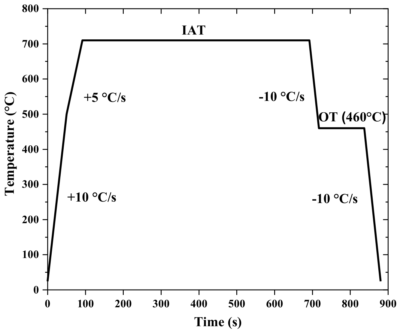
2.1. Starting Material and Heat Treatment Parameters

The chemical composition of the prototype med-Mn steel, as determined by inductively coupled plasma optical emission spectroscopy (ICP-OES) (Varian Inc.) and combustion analysis, is given in Table 1. The steel was vacuum cast as a 230 kg ingot, which was reheated and hot-rolled (HR) at a starting temperature of 1260 °C. The hot-roll finishing temperature was 906 °C, and the final thickness was 4 mm. The HR sheet was then tempered at 415 °C for 6 h to facilitate cold rolling. The tempered HR sheet was surface ground to a thickness of 3 mm, and the edges were trimmed prior to cold rolling. Finally, the HR sheet was cold-rolled (CR) to a final thickness of 1.4 mm. Two sample geometries were used in the heat treatment study: (i) 10 mm × 50 mm coupons were used for X-ray diffraction (XRD), scanning electron microscopy (SEM), and transmission electron microscopy (TEM) analysis, whereas (ii) 120 mm × 200 mm panels were annealed and processed into tensile samples. In all cases, the sheet rolling direction (RD) was parallel to the longitudinal axis of the sample.
The Ac1 and Ac3 temperatures for different heating rates (1–15 °C/s) were determined by dilatometry. These data were then used to develop the thermal processing cycles used in this study. The Ac1 and Ac3 temperatures for the as-received cold-rolled (i.e., CR) tempered martensite steel were 520 and 765 °C, respectively, for the CGL-compatible heating rate of 5 °C/s. On the basis of these findings, the CR samples were subjected to an austenisation heat treatment at 775 °C for 600 s, followed by gas quenching at −30 °C/s to produce a martensitic starting microstructure (M).
Based on the dilatometry results, a two-stage heat treatment was designed for the prototype med-Mn steel, schematically shown in Figure 1. The steel samples were first heated to an intercritical annealing temperature (IAT) and held for 60–600 s, followed by cooling at −10 °C/s to an overaging temperature (OT) of 460 °C and held for 20 s. The IATs were chosen so that they would result in targeted volume fractions of intercritical austenite with relatively high intercritical austenite C contents, where the latter was calculated using the ThermoCalc® TCFE 6 database. For this investigation, the chosen IATs were 675 and 710 °C, which would yield 0.50 and 0.75 volume fractions of intercritical austenite, respectively, per the dilatometry results. The OT was chosen to be compatible with the isothermal hold customarily carried out in industrial CGLs to thermally equilibrate the strip with the 460 °C Zn (Al, Fe) bath [26]. Finally, the samples were cooled to room temperature at −10 °C/s. All experiments were carried out in the McMaster Galvanizing Simulator (MGS) (Iwatani-Surtec) with an N2–5 vol % H2 process atmosphere and a dew point of −30 °C. Table 2 summarises the heat treatment parameters used in this study.

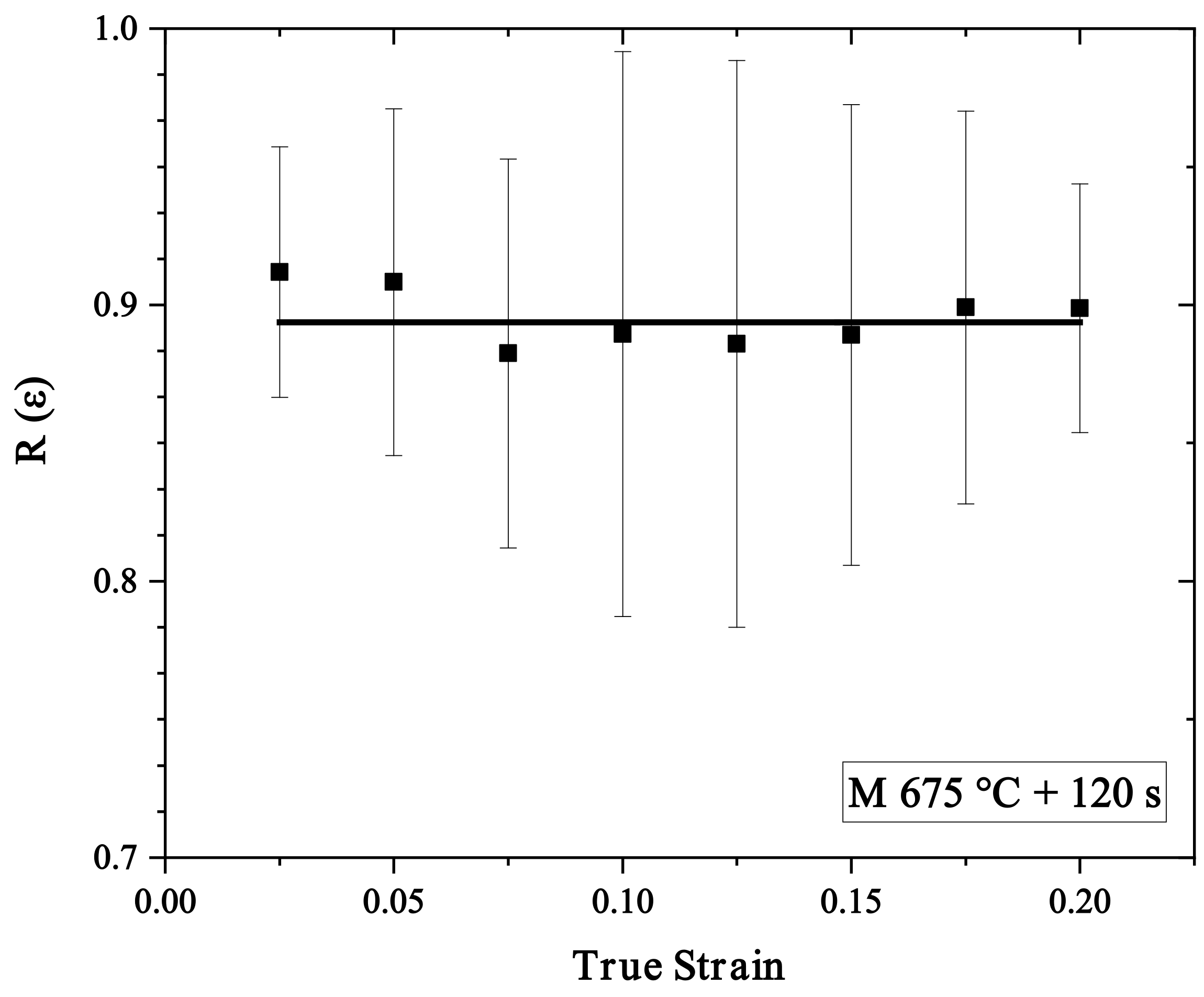
2.2. Mechanical Testing

An Instron 100 kN electromechanical load frame (MTS, Norwood, MA, USA) was used for uniaxial and interrupted tensile tests. All tests were conducted at room temperature with a crosshead speed of 1 mm/min. ASTM E8M subsize tensile samples [27] were cut from the 90 mm × 90 mm uniform heating area of the annealed 120 mm × 200 mm sample panels using electric discharge machining (EDM). EDM was used to avoid transformation of the retained austenite to martensite prior to testing. A conventional extensometer (25 mm) was used for measuring sample elongation. Tensile samples were tested in triplicate to ensure reproducibility.
Interrupted tensile tests were conducted for selected annealing conditions to measure the retained austenite to martensite transformation kinetics with applied strain. In this regard, samples were subjected to different levels of true strain (0.05, 0.10, 0.15, etc.) and were removed from the tensile frame after slowly reducing the tensile load to zero to avoid any significant rebound. The samples were then sectioned using a precision cutter (Struers), mounted, and lightly ground with 4000 grit SiC paper. The cross-sections of these samples were analysed using XRD to determine the retained austenite volume fraction as a function of applied true strain.
Load–unload–reload tests [28] were performed on M 675 °C + 120 s samples to qualitatively determine the contribution of kinematic hardening to the overall flow stress during plastic deformation. It must be emphasised that this test is not a true Bauschinger test, as a full load reversal after tensile loading of sheet samples would result in sample buckling. Thus, the results of this test should be taken as a qualitative assessment of the trends in the kinematic hardening component of the plastic flow stress. Samples were loaded to a pre-set true strain, which was increased by 0.025 after each unloading step up to fracture, as shown in Figure 2a. The back stress σB at a given true strain ε was determined using Equation (1):
σ B ε = σ F + σ R 2
where σF is the flow stress, and σR the reverse stress (determined by taking the 0.02% offset of the elastic unloading line, as shown in Figure 2b). This technique has the disadvantage of being dependent on the value of the offset strain selected but has the advantage of being relatively simple and compatible with the sheet geometry of the experimental materials. The ratio of the back stress to the instantaneous flow stress, R ε , was assessed using Equation (2):
R ε = σ B ε σ F ε
Under this formalism, a decline in R ε would be indicative of saturation of the kinematic hardening component of the flow stress. In the case of TRIP-aided steels, this would also be symptomatic of exhaustion of the retained austenite → martensite deformation induced transformation, which is related to the onset of damage in these advanced steels [10,28,29].

2.3. XRD Analysis

Retained austenite volume fractions were measured by using a Bruker D8 DISCOVER with a Co Kα (λ = 1.79026 Å) radiation source and a DAVINCI X-ray detector system (Bruker, Madison, WI, USA). Prior to XRD analysis, cross-sections of the annealed samples were ground using 4000 grit SiC paper to remove any effects arising from cutting the sample. ASTM E975-13 [30] was used to determine the sample retained austenite volume fraction using the (111), (200), and (220) austenite peaks, and the (110), (200), and (211) ferrite peaks.

2.4. Microstructural Characterisation

The microstructures of the sample cross-sections were analysed using a JEOL 7000F field emission scanning electron microscope (FE-SEM) (JEOL Ltd., Tokyo, Japan). Samples were prepared using standard metallographic techniques and etched using 2% nital. Carbon coating was used to reduce sample charging under the electron beam. An acceleration voltage of 10 keV, a working distance of 10 mm, and secondary electron image (SEI) mode were used in all cases. Additional nanoscale microstructural analysis was performed with a PHILIPS CM12 transmission electron microscope (TEM) (PHILIPS, Eindhoven, Netherlands) using an acceleration voltage of 200 keV. Selected interrupted tensile test samples were also analysed with TEM in order to determine if the retained austenite had undergone mechanical twinning and confirm TWIP as a plasticity enhancing mechanism during deformation. TEM thin foils were prepared by first grinding the samples to approximately 100 μm thickness using fine SiC papers, and then electropolishing at 16 V in a twin jet electropolisher (Struers) using an electrolyte of 10% perchloric acid in methanol held at −40 °C. TEM was also used to analyse carbon extraction replicas of selected CR and M samples to determine carbide size and size distribution. C-film extraction replicas were prepared using standard techniques. The carbide area fraction (a.f.) in the selected steel samples was determined by analysing the bright-field (BF) TEM micrographs with ImageJ (v.1.52a). Carbide chemistry was determined via energy dispersive spectroscopy (EDS) point analysis using a JEOL 2010F TEM with an Oxford INCA Pentafet energy dispersive X-ray spectrometer (JEOL Ltd., Tokyo, Japan) in scanning transmission electron microscopy (STEM) mode with a probe size of 1 nm and an acceleration voltage of 200 keV.

3. Results

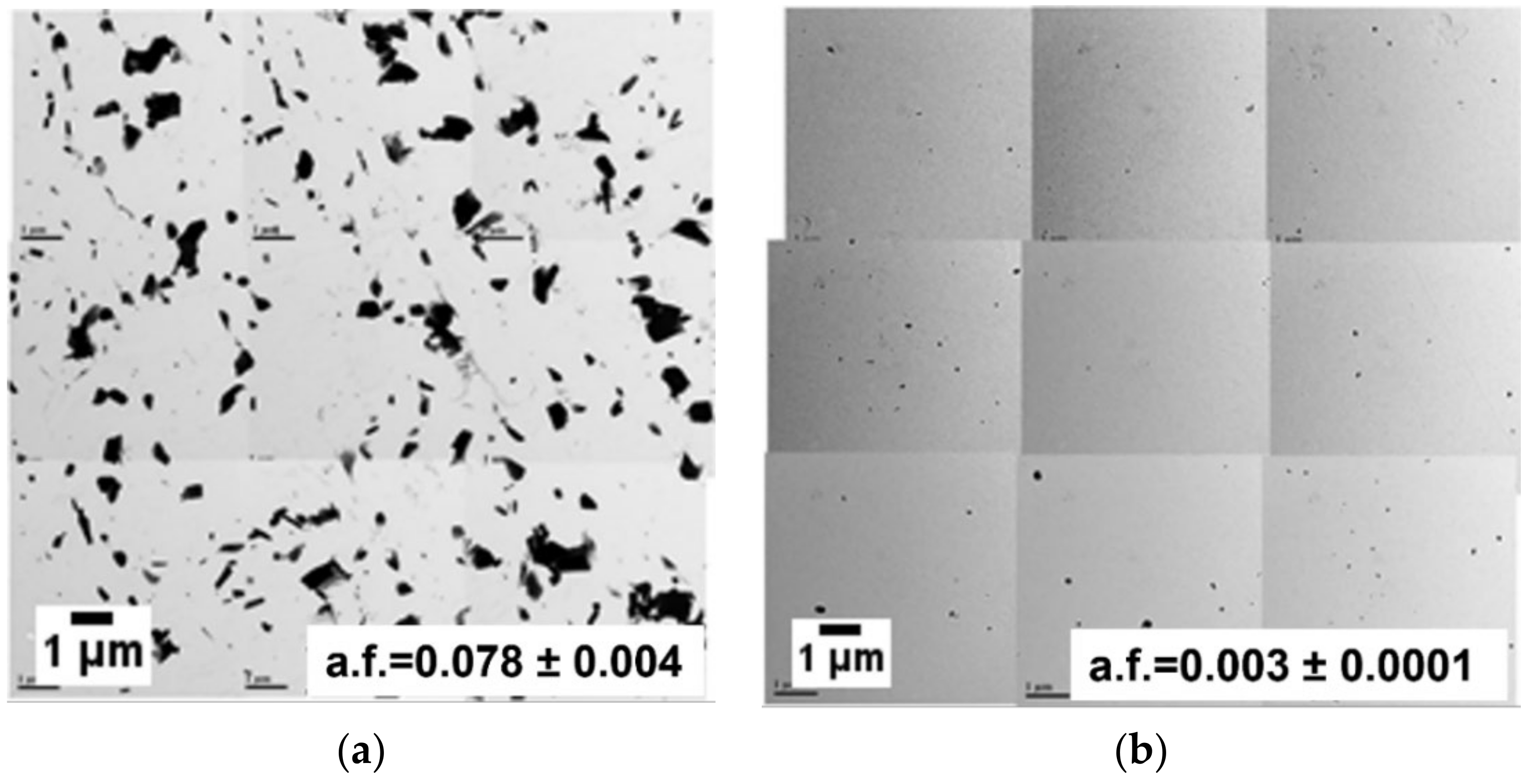
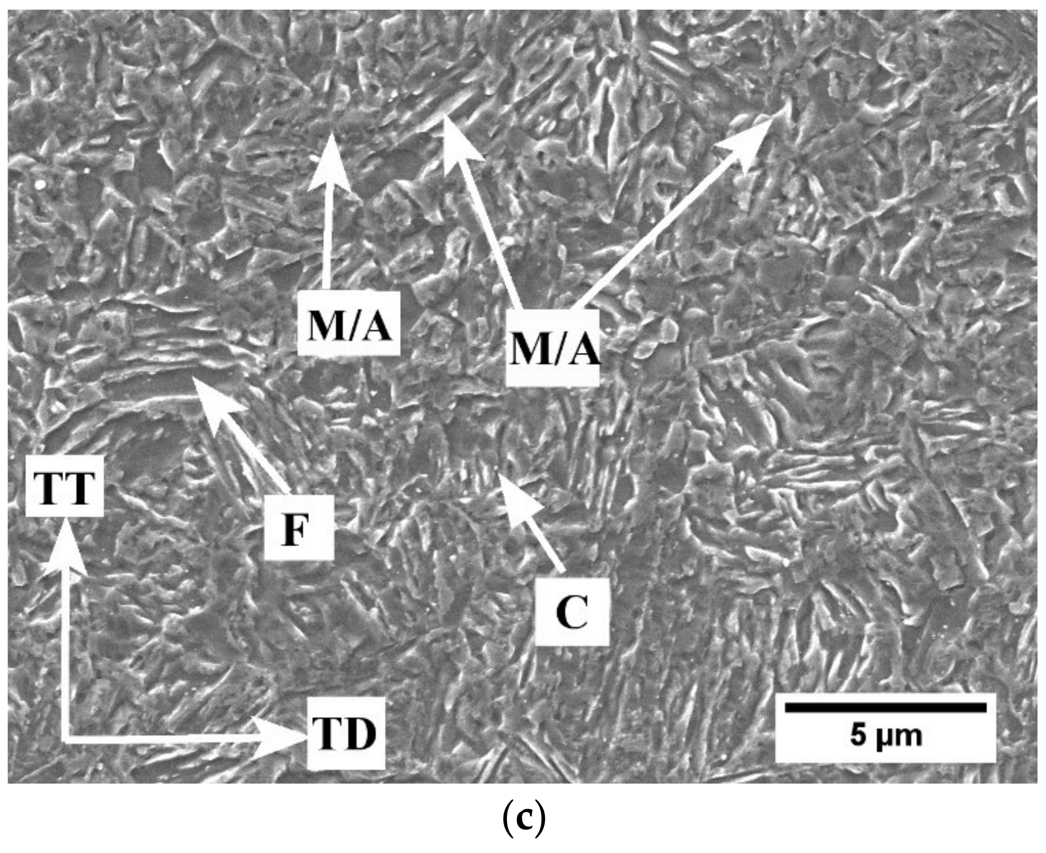
3.1. Starting Microstructure Characterisation

SEM micrographs of the CR and M starting microstructures are shown in Figure 3. The CR sample microstructure consisted of tempered martensite and carbides, whereas the M sample microstructure comprised martensite with no significant evidence of other phases visible at this length scale. TEM was used to analyse carbide size and size distribution in the starting microstructures using carbon extraction replicas. A montage of low-magnification bright field (BF) TEM micrographs of the CR and M extraction replicas are shown in Figure 4, which shows that the as-received cold-rolled CR sample had a significant area fraction (a.f. = 0.078 ± 0.004) of carbide particles, precipitated mainly along grain boundaries. However, almost all the carbide particles dissolved during the austenitizing heat treatment, as shown in Figure 4b, where there was a significant decrease (~96%) in carbide particles in the M starting microstructures (a.f. = 0.0028 ± 0.0001) versus the CR starting microstructure. This indicates that, after gas quenching, the carbon remained in the martensite phase as supersaturated carbon. In addition, the CR carbides were significantly larger that the M carbides. STEM EDS point analysis found that the irregular shaped carbides were M23C6-type Mn and Cr-rich carbides (as determined by ThermoCalc® TCFE 6 calculations and SAD pattern analysis [8]). Some rectangular Ti-rich carbides were also identified in both the CR and M starting microstructures. The error limits documented in Figure 4, and all subsequent figures and tables represent the 95% confidence interval of the mean.

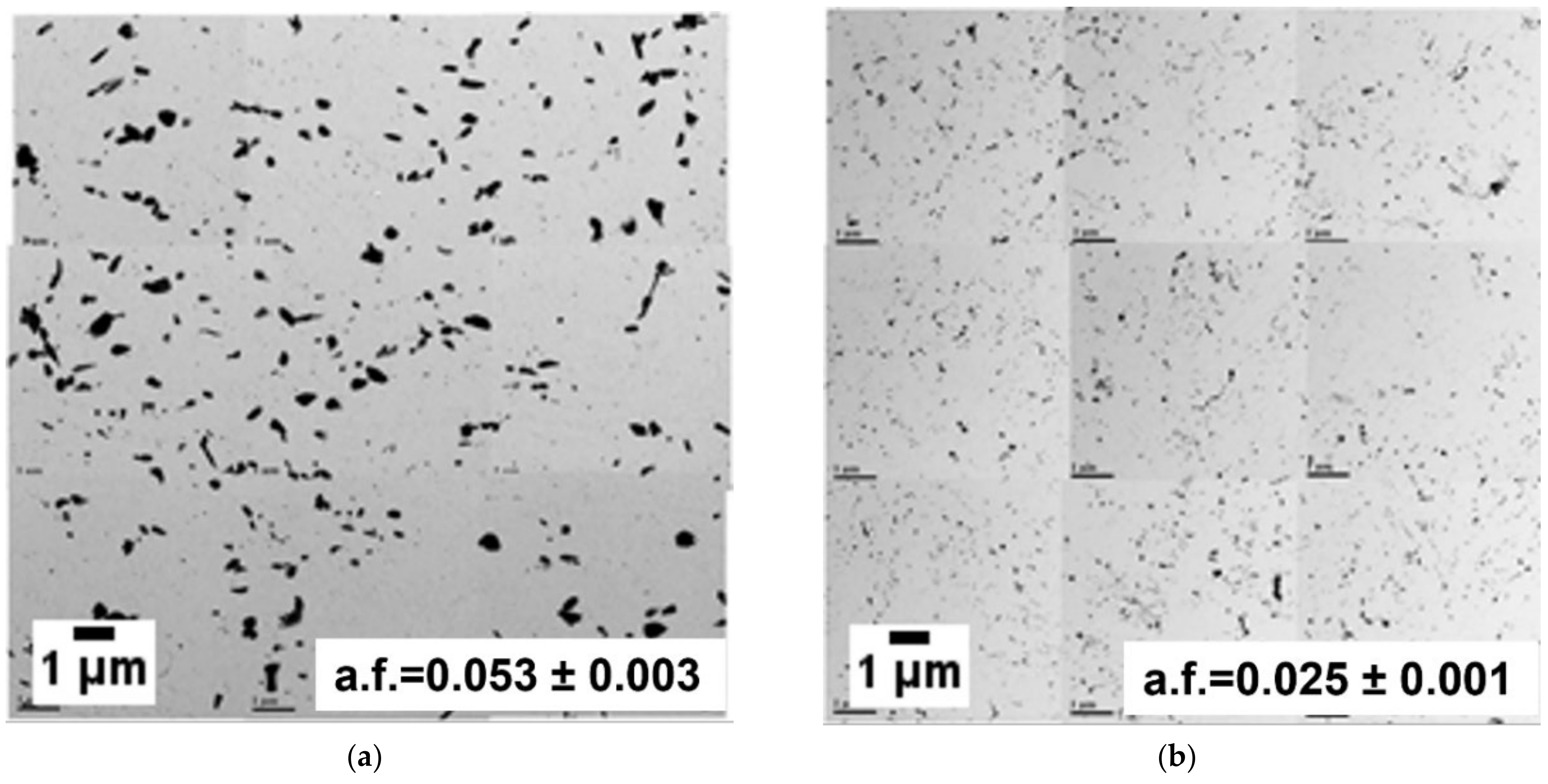
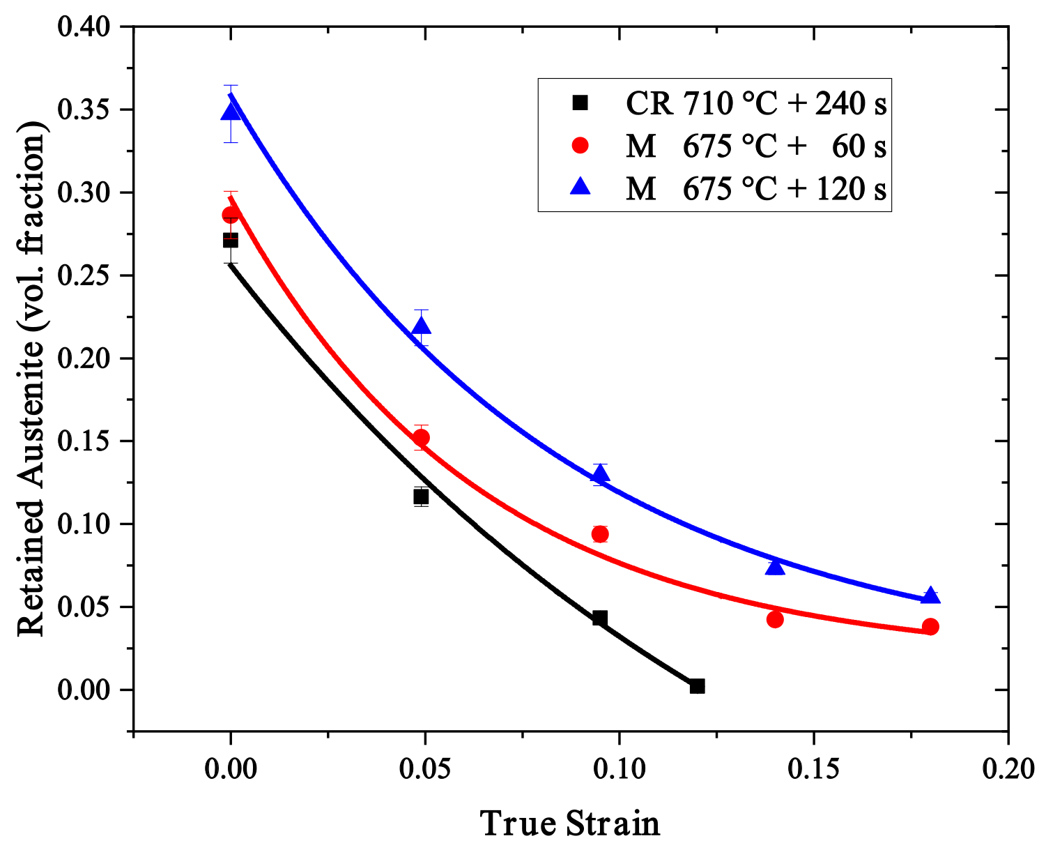
3.2. Retained Austenite Evolution

The volume fraction of retained austenite in the intercritically annealed (IA) steels is shown in Figure 5 for the CR and M samples. Figure 5a shows that the retained austenite volume fraction increased with IA holding time for both IATs for the CR starting microstructure. However, the volume fraction of retained austenite remained quite low for all 675 °C IA treatments. On the other hand, the CR 710 °C + 480 s and 600 s IAs yielded a high volume fraction of retained austenite (~0.37). This suggests the intercritical austenite in the CR 710 °C samples were more chemically stable and did not transform to fresh martensite during cooling. This is consistent with the estimated fresh martensite volume fraction, determined based on the difference between the equilibrium intercritical austenite and retained austenite volume fractions (Figure 6). A significant decrease in fresh martensite volume fraction was observed in the CR 710 °C samples, as shown in Figure 6a. Based on the above results, it was decided to move forward only with the CR 710 °C heat treatments for mechanical property assessment.
XRD results for the M samples showed a significantly different trend in retained austenite volume fraction as a function of IAT and IA holding time (Figure 5b). The retained austenite volume fraction increased with holding time for the 675 °C IAT up to 360 s and then decreased significantly for longer holding times. A decreasing trend in retained austenite volume fraction was also observed in the M 710 °C IAT samples for annealing times greater than 60 s (Figure 5b). This is attributed to lower intercritical austenite chemical stability for the 710 °C IAT samples, which then transformed to fresh martensite during final cooling. This is consistent with the significant increase in martensite volume fraction with increasing 710 °C IAT holding time, as shown in Figure 6b. From the above data, it was decided to focus on the M 675 °C IAT for subsequent analyses.

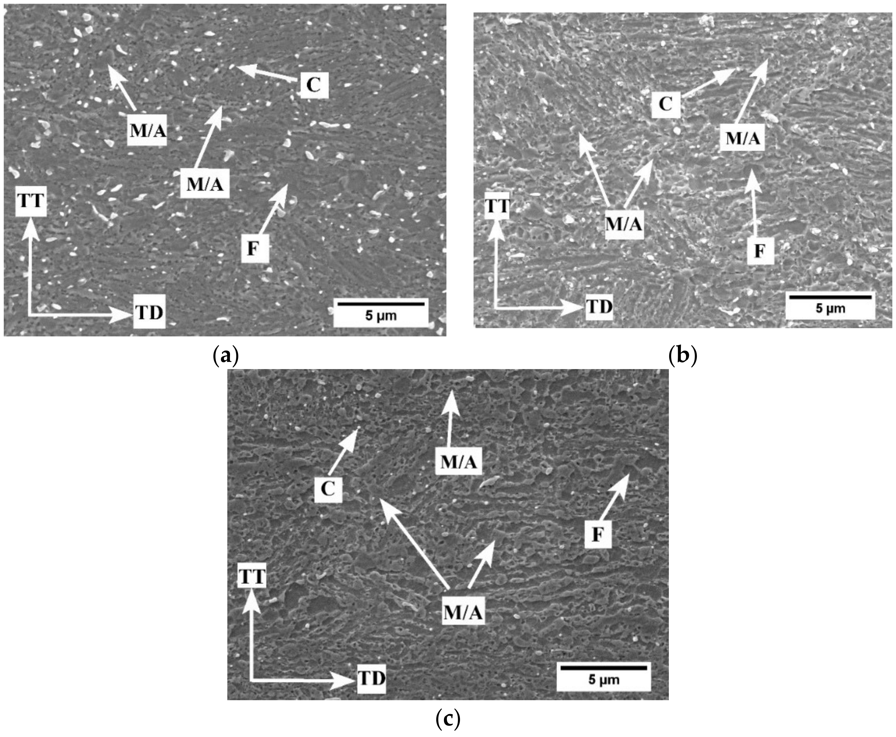
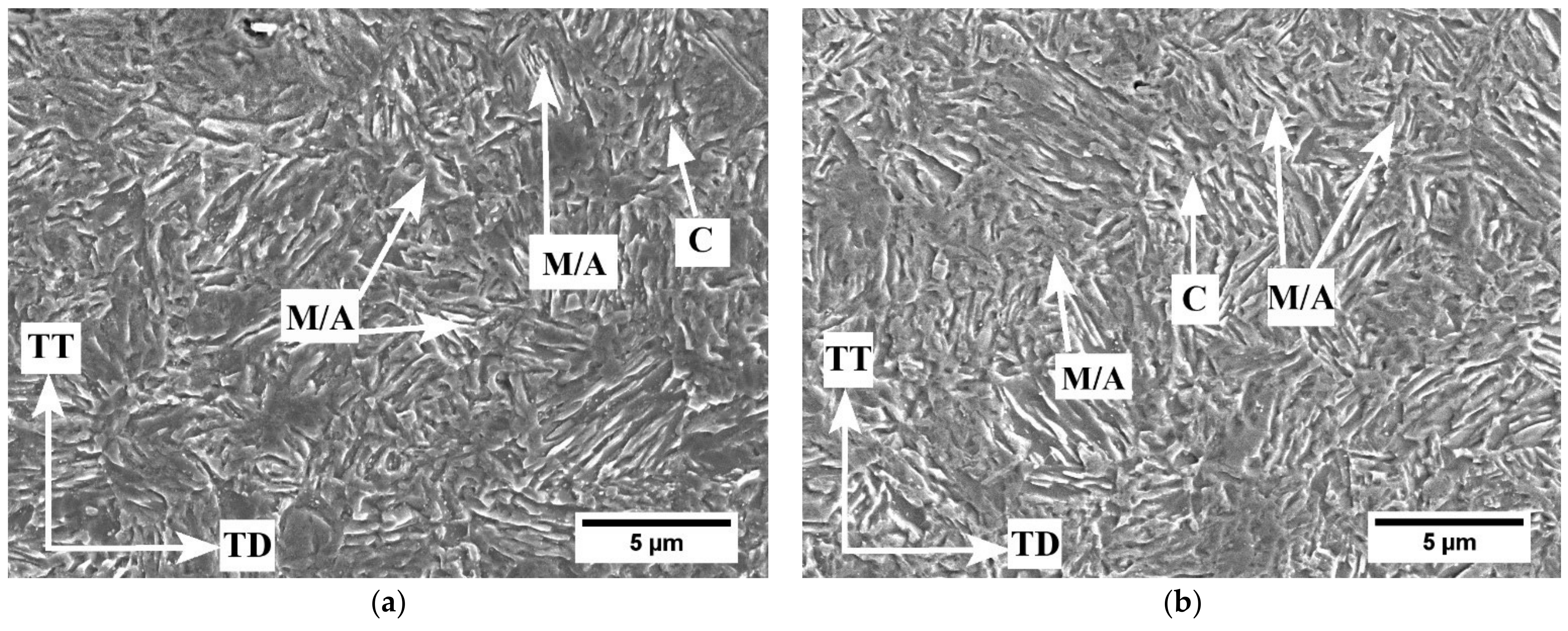
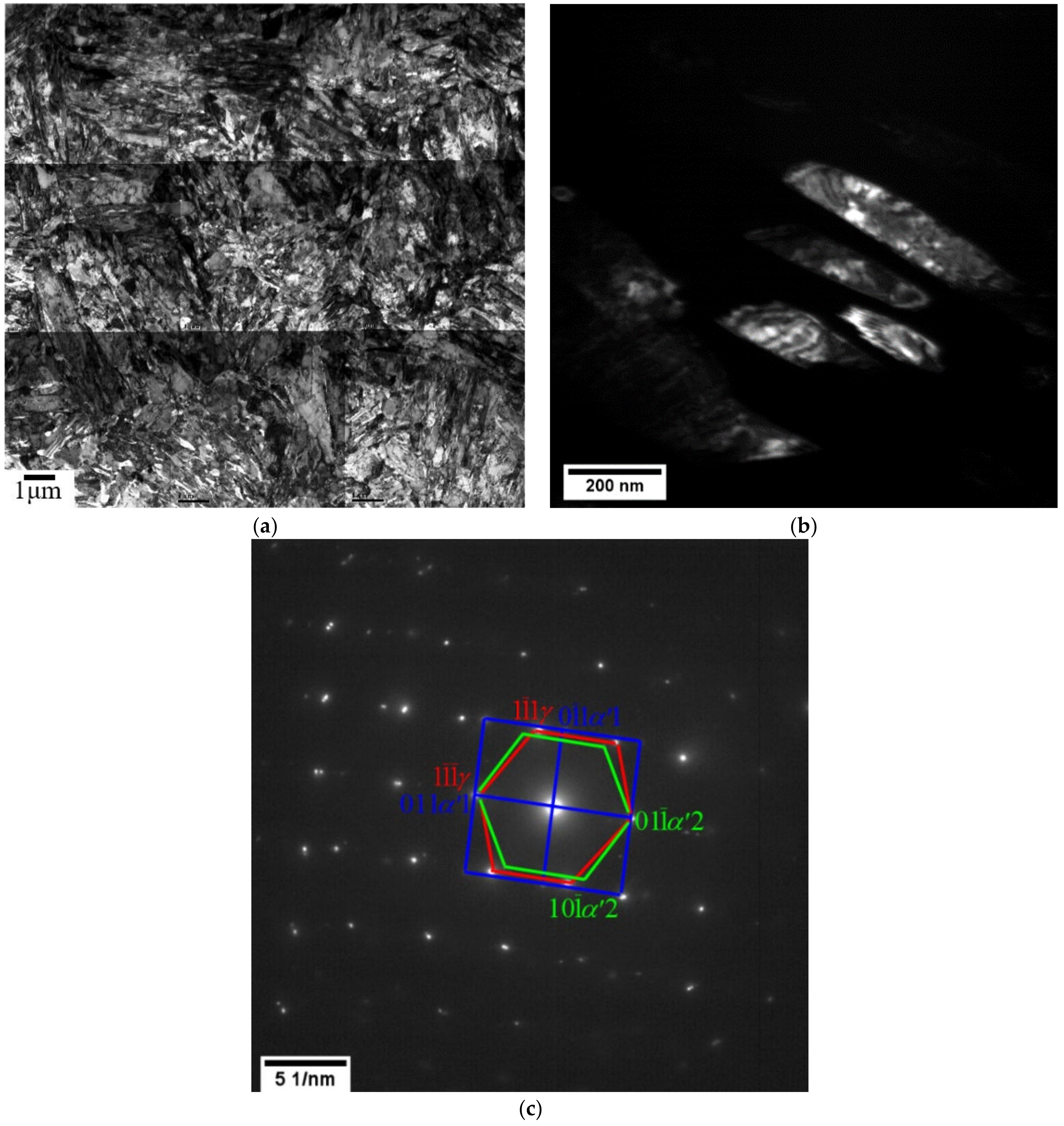
3.3. Microstructural Characterisation of Intercritically Annealed Samples

The microstructures of the intercritically annealed CR (710 °C) and M samples (675 °C) are shown in Figure 7 and Figure 8, respectively. All microstructures contained a mixture of ferrite, carbides, retained austenite, and martensite. However, it is difficult to distinguish between martensite and retained austenite with SEM. Nevertheless, the morphology of the martensite/retained austenite islands was mostly block-type in the case of the CR starting microstructure. Moreover, the martensite/retained austenite island fractions increased significantly with holding time at the 710 °C IAT for the CR starting microstructure (Figure 7), which was consistent with the XRD results (Figure 5a). On the other hand, both blocky and lamellar retained austenite were observed for the M starting microstructure (Figure 8). Furthermore, the relative fractions of lamellar or film-type retained austenite increased significantly for the M starting microstructures compared to the equivalent CR samples (i.e., Figure 7 vs. Figure 8). This general M microstructure is consistent with the observations reported by other researchers [8,9,10,11,14,20,22].
TEM was performed on annealed M samples to conduct fine-scale microstructural analysis. Both bright (BF) and dark field (DF) images were used to probe the ultrafine microstructures. The BF and DF images and corresponding selected area diffraction (SAD) patterns of the representative M starting microstructure annealed at 675 °C for 120 s (i.e., M 675 °C + 120 s) are shown in Figure 9. A low-magnification montage of multiple BF TEM images (Figure 9a) revealed a complex mixture of ultrafine ferrite, retained austenite, and martensite. DF TEM imaging and SAD were used to identify the phases based on their crystal structures. The 110 γ austenite diffraction pattern was selected to produce DF image of the retained austenite microstructure, which comprised a lamellar morphology, as shown in Figure 9b. This retained austenite morphology is generally considered to be more chemically and mechanically stable compared to blocky retained austenite due to the plastic constraint imposed by the surrounding martensite. The SAD patterns (Figure 9c) delineated two orientation relationships between the ferrite/martensite and retained austenite. The orientation relationship between α′1 ferrite/martensite and retained austenite, determined to be 100   α 1 110 γ + 011   α 1 1 1 ¯ 1 ¯ γ , closely corresponds to the Nishiyama–Wasserman (N–W) orientation relationship [31,32]. Furthermore, the orientation relationship for α′2 ferrite/martensite and retained austenite, 111   α   2 110 γ + 011   α   2 1 1 ¯ 1 ¯ γ , corresponded to the Kurdjumov–Sacks (K–S) orientation relationship [33]. This suggests the retained austenite grew from the parent martensite or, more likely, from pre-existing interlath retained austenite films during intercritical annealing. The latter would be consistent with the significantly more rapid austenite reversion kinetics observed for the M starting microstructures, as no nucleation event was required [10,11].
Carbide distribution was analysed using extraction replicas from the CR 710 °C + 120 s and M 675 °C + 120 s samples in order to identify the source of carbon partitioning during intercritical annealing and directly compare the C available for intercritical austenite stabilisation for comparable IA annealing times. Montage BF TEM micrographs of these samples are shown in Figure 10. In addition, the area fractions of carbides for the two starting microstructures and above heat treatments are shown in Figure 11. The carbide particle size decreased considerably for the CR 710 °C + 120 s sample, as can be seen by comparing Figure 4a, Figure 10a, and Figure 11. This suggests that the carbides dissolved during the IA and likely acted as a C source to chemically stabilise a significant fraction of the intercritical austenite such that it did not transform to martensite upon quenching, thereby allowing it to be retained at room temperature and result in the observed high fractions of retained austenite and low fractions of martensite (Figure 6a). This is consistent with the mechanism proposed by Arlazarov et al. [34] where blocky polygonal intercritical austenite formed during IA treatment from a cold-rolled starting microstructure. Similar blocky retained austenite was also observed in annealed CR samples (Figure 7).
Contrastingly, the supersaturated C in martensite from the M starting microstructures likely partitioned into the intercritical austenite during intercritical annealing. Moreover, carbide particles precipitated at the grain boundaries during M intercritical annealing, as shown in Figure 4b and Figure 10b. This is consistent with the carbide area fraction analysis, which confirmed a significant increase in carbide particles in the M 675 °C + 120 s sample (Figure 11). However, the precipitated carbide fraction in the case of the M 675 °C + 120 s microstructure was significantly less than that of its CR counterpart, indicating that the overall C mass balance favours the bulk microstructure rather than carbide precipitation.

3.4. Mechanical Properties

Tensile tests were conducted on the as-received microstructures and on intercritically annealed samples with significant volume fractions of retained austenite. The resulting engineering stress–engineering strain and true stress–true strain curves are shown as a function of IA temperature and holding time in Figure 12. Tensile property results are summarised in Table 3. The true stress–true strain curves (Figure 12b) were used to determine the instantaneous work hardening rates (dσ/dε), which were plotted as a function of true strain in order to detect the activation of plasticity enhancing mechanisms (Figure 12c,d). To determine the most promising heat treatments, the UTS × TE product for each sample was assessed with respect to 3G AHSS target mechanical properties [6].
The as-received CR microstructure had a high UTS and low TE, which resulted in a relatively low UTS × TE product of 10,933 MPa% (Table 3). For the selected 710 °C intercritically annealed CR samples, a decreasing trend in yield strength (YS) and UTS was observed with increasing IA holding time. However, the TE increased significantly with increasing IA time, with the highest TE (~21.6%) being observed for the 600 s IA holding time, as shown in Figure 12a and Table 3. This trend was attributed to the successful activation of the TRIP/TWIP effects during deformation of these samples. As shown in Figure 12c, for the CR 710 °C + 240 s and CR 710 °C + 600 s samples, the work hardening rate initially decreased during the elastoplastic transition and then gradually increased with increasing true strain up to ε = 0.08 and ε = 0.10, respectively. The work hardening rate then decreased with increasing strain until failure. This work hardening rate trend is consistent with a steel where plasticity enhancing mechanisms (TRIP and/or TWIP) are activated during deformation [8,9,10,11,12,14,21,22]. As noted in Table 3, this resulted in the CR 710 °C + 600 s heat treatment significantly exceeding the general 3G AHSS UTS × TE target (i.e., approximately 30,456 MPa%). Nevertheless, the relatively long IA holding time of 600 s required to produce these properties is not consistent with CGL thermal processing conditions as the steel substrate usually resides only a total of 3–5 min in the CGL furnace.
Contrastingly, the CR 710 °C + 120 s sample work hardening rate decreased with increasing true strain to failure, with no apparent activation of either the TRIP or TWIP effects being evident. This is a typical work hardening curve for a dual phase (DP) steel [35] or for an AHSS where the TRIP effect is rapidly exhausted at low strains owing to insufficient chemical and mechanical stability of the retained austenite [36]. As a result, a significantly lower TE was observed for the CR 710 °C + 120 s IA treatment, resulting in a UTS × TE product (~20,839 MPa%) below the target 3G AHSS mechanical properties (see Table 3).
By way of contrast, the M samples met 3G AHSS target properties with the lower 675 °C IAT and shorter holding times of 60–360 s (Table 3). The YS decreased while the UTS increased with increasing IA holding time, but the TE was relatively insensitive to IA holding time and remained above 20% for all the selected M starting microstructure samples (Table 3). An increase in the work hardening rate (marked with arrows in Figure 12d) was observed for these heat treatments, indicating the activation of plasticity enhancing mechanisms. A high work hardening rate was sustained with increasing true strain, resulting in high UTS and TE in these samples. This resulted in a high UTS × TE product (≥30,000 MPa%) with the highest UTS × TE product (37,064 MPa%) being observed for the M 675 °C + 120 s sample (Table 3).
This wider IA window for the attainment of 3G properties for the M starting microstructures can be attributed to its higher retained austenite chemical and mechanical stability (i.e., lower M S and M S σ temperatures), allowing the retained austenite (γret) to transform gradually during deformation, thereby resulting in the maintenance of high work hardening rates (Figure 12d). Evidence for this more gradual γret → M transformation was provided by the interrupted tensile test results for the M 675 °C IAT samples annealed for 60 s and 120 s (Figure 13), which showed the desired gradual transformation kinetics for both treatments. The retained austenite transformation rate was rapid at lower strains; however, in both cases, a relatively gradual transformation of retained austenite followed with increasing strain to failure. As a result, a continuous supply of fresh reinforcement phase (martensite) and geometrically necessary dislocations (GNDs) was maintained during deformation of these samples which, in turn, contributed to sustaining high work hardening rates and delaying the onset of necking. Contrastingly, a significantly faster retained austenite to martensite transformation kinetic was observed for the CR 710 °C + 240 s sample, as shown in Figure 13. This suggests a lower retained austenite stability in the CR 710 °C + 240 s sample compared to the M 675 °C + 60 s and M 675 °C + 120 s samples. As a result, the TRIP effect was exhausted at lower strains for the CR 710 °C + 240 s sample, resulting in a UTS × TE product (~19,800 MPa%) below the general target mechanical properties for 3G AHSS.
Additional TEM analyses were carried out on the interrupted tensile test samples to determine whether mechanical twinning occurred during deformation. Figure 14 shows the TEM micrographs and corresponding SAD patterns of the M 675 °C + 120 s sample which was interrupted at ε = 0.10 during the uniaxial tensile test. Planar defects were observed in DF TEM, marked by the red arrows in Figure 14b. Although distinct twin spots were not identified in the SAD patterns (Figure 14c), a comparison of Figure 9b and Figure 14b reveals a substantial increase in the population of planar defects, which can be stacking faults or mechanical twins or a mixture thereof. These planar defects decreased the dislocation mean free path during deformation and thereby, also aided in sustaining high work hardening rates alongside the TRIP effect. Furthermore, the work hardening curve (Figure 12d) for this sample is consistent with those in which both the TRIP and TWIP effects were activated during deformation of a medium-Mn steel [37]. This suggested that some form of the TWIP effect was active alongside the TRIP effect during deformation.
The back stress/flow stress ratio, R ε , was determined from load–unload–reload tests for the M 675 °C + 120 s treatment. It should be noted that the true strain at UTS for this treatment was approximately ε = 0.22. It should be recalled that this modified Bauschinger test does not provide quantitative back stress values, but rather a trend in the ratio of the kinematic hardening component as a portion of the overall flow stress and is indicative of the saturation of the kinematic hardening component of the flow stress versus the isotropic hardening component. The results are shown in Figure 15. It can be seen that R ε did not change significantly during plastic deformation up to ε = 0.20, suggesting that kinematic hardening did not saturate owing to continuous supply of fresh obstacles to dislocation motion. This finding is consistent with the retained austenite transformation kinetic results (Figure 13), which showed that the TRIP effect was not exhausted until high strains (i.e., ε ≅ 0.18). As shown in Figure 14, mechanical twinning did occur within the retained austenite, indicating that mechanical twinning, the so-called dynamic Hall–Petch effect, also likely contributed to the observed sustained high work hardening rates. However, the relative contributions of these two plasticity-enhancing mechanisms cannot be ascertained in the present case.

4. Discussion

The starting microstructure of the prototype medium-Mn steel had a significant effect on the formation, growth, and C partitioning mechanism of the intercritical austenite. Carbide evolution during intercritical annealing revealed that the nucleation and growth of the intercritical austenite likely occurred on the carbide particles of the CR starting microstructure (Figure 4a vs. Figure 10a and Figure 11), where the C source for chemically stabilising the CR intercritical austenite was the dissolution of the carbide particles. Hence, longer IA holding times or higher IATs were required to obtain the desired fractions of retained austenite owing to the nucleation barrier for austenite and the required C dissolution kinetics (Figure 5a). This is consistent with the decreasing fresh martensite volume fraction for CR samples annealed at 710 °C (Figure 6a), indicative of large fractions of chemically stable retained austenite being formed. This trend is also consistent with those observed for various medium-Mn steels [13,38,39]. However, for the CR 710 °C IAT, the 3G property targets were not achieved for IA times of less than 240 s (Table 3). As the steel substrate usually resides for a total of 3–5 min in the CGL furnace, these IA parameters are incompatible with CGL thermal processing windows [40].
Contrastingly, XRD results (Figure 5b) showed that a 675 °C IAT and shorter IA holding times of 60 s and 120 s were sufficient to result in greater than 0.30 volume fraction of chemically and mechanically stable retained austenite (Figure 13) for the M starting microstructure owing to faster austenite reversion kinetics, resulting in these treatments achieving 3G target properties (Table 3). As reported by Nakada et al. [23], the martensite to austenite transformation is more rapid than that from tempered martensite due to the fact that the martensite is highly strained and C supersaturated. Hence, less energy is required for the nucleation and growth of intercritical austenite at the martensite lath boundaries during intercritical annealing, resulting in the observed rapid reversion of the martensite to austenite. Furthermore, the pre-existing interlath retained austenite in the martensitic starting microstructure was also reported to grow during IA treatment owing to not having a nucleation barrier [41]. The lamellar or film-type retained austenite reported in these studies was observed in the annealed M starting microstructures, as shown in Figure 8 and Figure 9. This is consistent with the K–S and N–W orientation relationships observed between the martensite and retained austenite in the annealed M samples (Figure 9). Moreover, carbon extraction replica analysis (Figure 4b vs. Figure 10b and Figure 11) showed that the C supersaturated martensite was likely the main source for C partitioning into the intercritical austenite. This is consistent with observed results in previous research conducted on med-Mn steels with martensitic starting microstructures [10,11,20,22,34,42]. As a result of the more rapid partitioning of C from the adjacent, C supersaturated martensite and lower energy barrier for growth, the intercritical austenite was chemically stable at room temperature and did not transform to martensite during final cooling, resulting in the relatively high volume fraction of retained austenite in the final microstructure versus the equivalent heat treatments performed on the CR starting microstructures (Figure 5).
However, this stabilisation had a kinetic limit, as shown by the significant decrease in retained austenite (Figure 5b) along with the increase in fresh martensite volume fraction (Figure 6b) observed for the M starting microstructures annealed at 675 °C for longer than 360 s, and at 710 °C for longer than 60 s. This suggests that the intercritical austenite formed under those IA conditions was no longer sufficiently C enriched to be chemically stable at room temperature and transformed to martensite during final cooling. As revealed by the C extraction replica analysis from the M starting microstructure (Figure 4b) versus the M 675 °C + 120 s treatment (Figure 10b) and summarised in Figure 11, the M 675 °C IA resulted in carbide precipitation and a reduction in the C available to stabilise the intercritical austenite. It would be expected that carbide precipitation would increase for longer holding times and would be accelerated for the 710 °C IAT. As a result, less C was available to partition into the intercritical austenite and provide sufficient chemical stabilisation, resulting in the observed reduction in retained austenite fraction for IA times greater than 360 s.
The mechanical properties observed from the intercritical heat treatments were a strong function of the deformation-induced retained austenite transformation kinetics, which, in turn, depended directly on the retained austenite volume fraction and stability. Per Table 3, the CR starting microstructures subjected to the CR 710 °C IAT + 120 s and CR 710 °C + 240 s treatments did not achieve 3G AHSS target mechanical properties. These results can be linked to the relatively low retained austenite volume fractions (Figure 5a), the high fraction of fresh martensite (Figure 6a), and rapid exhaustion of the TRIP effect (Figure 13) likely arising from insufficient C partitioning to the retained austenite during the intercritical anneal. This latter hypothesis is reinforced by the carbide analysis shown in Figure 11, which implies that significantly less C was available for intercritical austenite stabilisation from short-time intercritically annealed CR starting microstructures. As shown by the tensile and work hardening curves (Figure 12), the factors combined to result in a steel with the characteristics of a high-strength DP steel rather than the desired 3G characteristics. It required prolonged 710 °C annealing times greater than 240 s to obtain the desired volume fractions of chemically stable retained austenite which allowed for attainment of the target 3G properties (Table 3). Although promising for other heat treatment processes, these longer IA times are not, however, compatible with CGL process windows.
Contrastingly, high volume fractions (˃0.30) of chemically and mechanically stable retained austenite were achieved for the M 675 °C + 60–360 s treatments owing to the factors discussed above. The resultant TRIP effect was not exhausted until relatively high strains (≅0.20, Figure 13), resulting in a sustained high work hardening rate (Figure 12) due to the continuous introduction of fresh martensite, GNDs, and planar defects (Figure 14) such that the kinematic work hardening component was sustained as a relatively constant fraction of the overall flow stress (Figure 15). The factors combined to allow for the mechanical properties to achieve the required strength/ductility balance to meet 3G property targets for IA times and temperatures that are compatible with the process window of the CGL (Table 3). Overall, it can be concluded that the present prototype alloy, when utilising the martensitic starting microstructure, is a promising material for CGL processing and 3G AHSS structural applications. Furthermore, it has been shown that a model alloy of similar composition—when properly processed—can be successfully galvanized [43]. The subject of the galvanizing of the present prototype 3G AHSS will be addressed in subsequent contributions.

5. Conclusions

A prototype 0.2 C–6 Mn–1.7 Si–0.4 Al–0.5 Cr (wt %) med-Mn steel was investigated to determine the effects of starting microstructure and intercritical annealing (IA) time/temperature on the microstructural evolution and mechanical property development with the overall objective of realising 3G AHSS properties using a CGL-compatible thermal treatment. From the results of this investigation, it can be concluded that:
1.
For the as-received CR starting microstructure, an IAT of 710 °C and time (>240 s) were required to provide sufficient volume fractions of stable retained austenite to achieve target 3G properties. This was due to the relatively slow austenite reversion kinetics arising from the kinetic barriers requiring nucleation of austenite and the dissolution of carbides to provide sufficient C to stabilise the retained austenite.
2.
The thermal processing parameters required to achieve 3G mechanical properties from the CR starting microstructures are not CGL-compatible.
3.
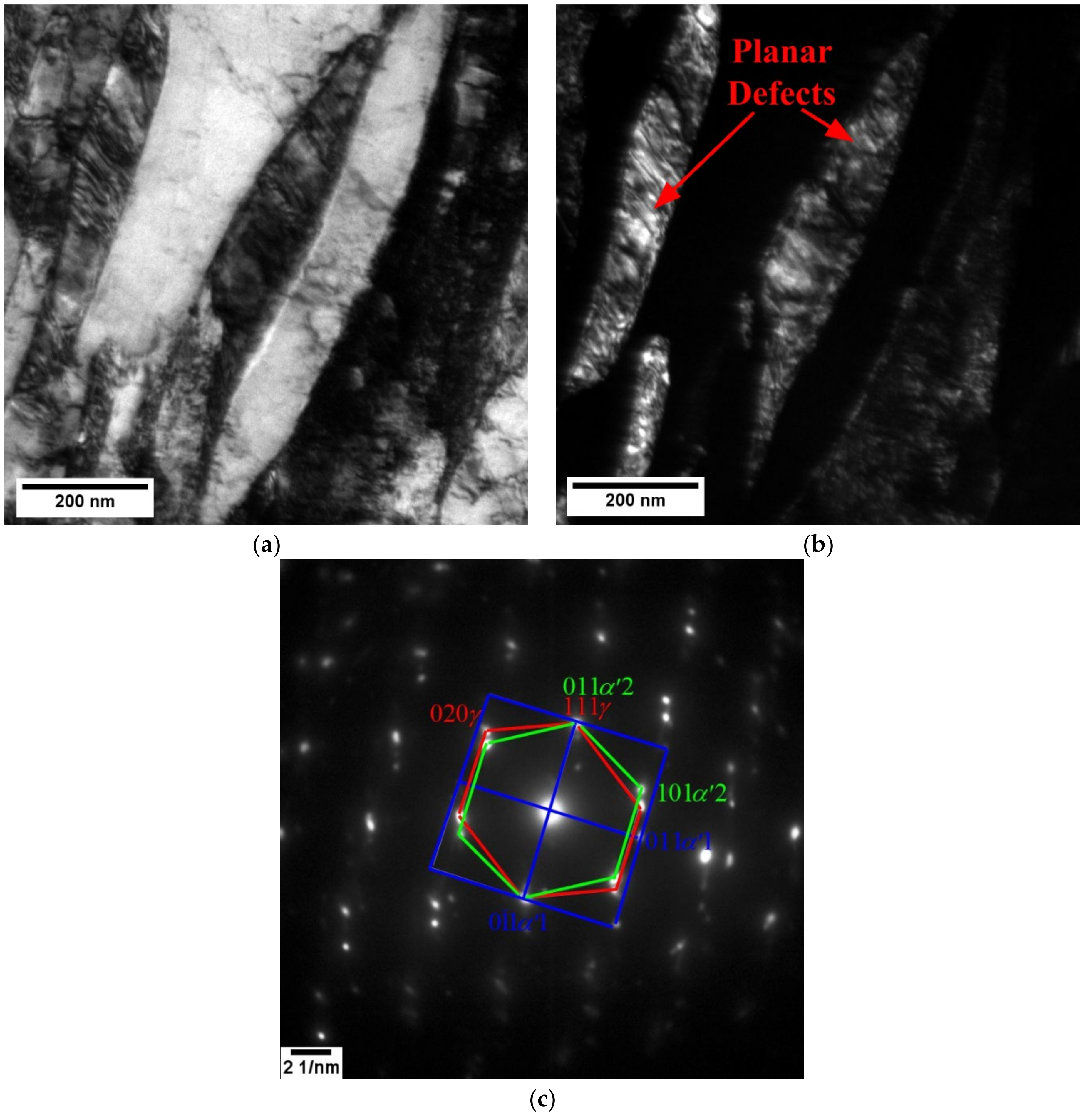
For the M starting microstructure, an IAT of 675 °C + 60–360 s provided large fractions of chemically and mechanically stable retained austenite such that 3G AHSS target properties were realised through a gradual exhaustion of the TRIP effect and the formation of planar defects in the retained austenite during deformation such that high sustained work hardening rates were obtained. This was due to the direct growth of intercritical retained austenite from pre-existing interlath retained austenite films and the relatively rapid partitioning of C from the surrounding C supersaturated martensitic matrix.
4.
For this reason, the prototype steel in the M starting microstructure condition is a promising candidate for a CGL-compatible med-Mn 3G AHSS.

Author Contributions

Conceptualisation, J.R.M.; investigation, K.M.H.B., X.W. and E.A.M.; formal analysis, K.M.H.B. and X.W.; writing—original draft preparation, K.M.H.B.; writing—review and editing, J.R.M. and K.M.H.B.; supervision, J.R.M.; project administration, J.R.M.; funding acquisition, J.R.M. All authors have read and agreed to the published version of the manuscript.

Funding

This research was funded by the International Zinc Association Galvanized Autobody Partnership (IZA-GAP) program (ZCO-53-2).

Data Availability Statement

The raw/processed data required to reproduce these findings cannot be shared at this time as the data form part of an ongoing study.

Acknowledgments

The authors thank the members of the International Zinc Association Galvanized Autobody Partnership (IZA-GAP) program for their financial support. U.S. Steel Research is gratefully acknowledged for the provision of the substrates used in this study. The authors also thank Chris Butcher (SEM), Victoria Jarvis (XRD), and the staff of the McMaster Steel Research Centre (SRC) and Centre for Automotive Materials and Corrosion (CAMC) for their technical support.

Conflicts of Interest

The authors declare that they have no known competing financial interests or personal relationships that could have appeared to influence the work reported in this paper. The authors declare no conflict of interest.

References

  1. Matlock, D.K.; Speer, J.G.; Moor, E.D.; Gibbs, P.J. Recent Developments in Advanced High Strength Sheet Steels for Automotive Applications: An Overview. Jestech 2012, 15, 1–12. [Google Scholar]
  2. Moor, E.D.; Gibbs, P.J.; Speer, J.G.; Matlock, D.K.; Schroth, J.G. Strategies for Third Generation Advanced High Strength Steel Development. AIST Trans. Iron Steel Technol. 2010, 7, 133–144. [Google Scholar]
  3. Takahashi, M.; Yoshida, H.; Hiwatashi, S. Properties of TRIP type high strength steels. In Proceedings of the International Conference on TRIP-Aided High Strength Ferrous Alloys, Ghent, Belgium, 19–21 June 2002; pp. 103–111. [Google Scholar]
  4. Schutte, C. DOE Focuses on Developing Materials to Improve Vehicle Efficiency. In SAE Technical Paper Series; SAE International: Warrendale, PA, USA, 2015. [Google Scholar] [CrossRef]
  5. Hector, L.G., Jr. The Next Generation of Advanced High Strength Steels—Computation, Product Design and Performance. In Proceedings of the 12th Annual Great Designs in Steel Seminar, Livonia, MI, USA, 1 May 2013. [Google Scholar]
  6. Matlock, D.K.; Speer, J.G. Design Considerations for the Next Generation of Advanced High Strength Steel Sheets. In Proceedings of the 3rd International Conference on Structural Steels, Ed. by H.C. Lee, the Korean Institute of Metals and Materials, Seoul, Korea, 22–24 August 2006; pp. 774–781. [Google Scholar]
  7. Suh, D.W.; Ryu, J.H.; Joo, M.S.; Yang, H.S.; Lee, K.; Bhadeshia, H.K.D.H. Medium-Alloy Manganese-Rich Transformation-Induced Plasticity Steels. Metall. Mater. Trans. A 2013, 44, 286–293. [Google Scholar] [CrossRef] [Green Version]
  8. Bhadhon, K.M.H.; McDermid, J.R.; Wang, X.; McNally, E.; Goodwin, F.E. Fine-scale microstructure characterization and mechanical properties of CGL-compatible heat treated medium-Mn TRIP steel. In Proceedings of the 11th Conference on Zinc and Zinc alloy Coated Steel Sheet, Galvatech 2017, ISIJ Int., Tokyo, Japan, 12–14 November 2017; pp. 493–500. [Google Scholar]
  9. Pallisco, D.M.; Bhadhon, K.M.H.; Patel, V.; Pourmajidian, M.; Goodwin, F.E.; McDermid, J.R. Galvanizing of medium-Manganese third generation advanced high strength steels. In Proceedings of the 4th International Conference on Medium and High-Manganese Steels, Aachen, Germany, 31 March–3 April 2019; Volume 9–11, pp. 375–378. [Google Scholar]
  10. Pallisco, D.M.; McDermid, J.R. Mechanical property development of a 0.15C–6Mn–2Al–1Si third-generation advanced high strength steel using continuous galvanizing heat treatments. Mater. Sci. Eng. A 2020, 778, 139111. [Google Scholar] [CrossRef]
  11. Patel, V. Microstructure and Mechanical Properties of Medium Mn Steel; McMaster University: Hamilton, Canada, 2019. [Google Scholar]
  12. Lee, S.; Lee, S.-J.; Kumar, S.; Lee, K.; De Cooman, B.C. Localized Deformation in Multiphase, Ultra-Fine-Grained 6 Pct Mn Transformation-Induced Plasticity Steel. Metall. Mater. Trans. A 2011, 42, 3638–3651. [Google Scholar] [CrossRef] [Green Version]
  13. Lee, S.; De Cooman, B.C. On the Selection of the Optimal Intercritical Annealing Temperature for Medium Mn TRIP Steel. Metall. Mater. Trans. A 2013, 44, 5018–5024. [Google Scholar] [CrossRef] [Green Version]
  14. Gibbs, P.J.; De Moor, E.; Merwin, M.J.; Clausen, B.; Speer, J.G.; Matlock, D.K. Austenite Stability Effects on Tensile Behavior of Manganese-Enriched-Austenite Transformation-Induced Plasticity Steel. Metall. Mater. Trans. A 2011, 42, 3691–3702. [Google Scholar] [CrossRef]
  15. Hu, B.; Luo, H. A novel two-step intercritical annealing process to improve mechanical properties of medium Mn steel. Acta Mater. 2019, 176, 250–263. [Google Scholar] [CrossRef]
  16. Jing, S.; Ding, H.; Ren, Y.; Cai, Z. A new insight into annealing parameters in tailoring the mechanical properties of a medium Mn steel. Scr. Mater. 2021, 202, 114019. [Google Scholar] [CrossRef]
  17. Ma, Y.; Song, W.; Zhou, S.; Schwedt, A.; Bleck, W. Influence of Intercritical Annealing Temperature on Microstructure and Mechanical Properties of a Cold-Rolled Medium-Mn Steel. Metals 2018, 8, 357. [Google Scholar] [CrossRef] [Green Version]
  18. Bansal, G.K.; Madhukar, D.A.; Chandan, A.K.; Ashok, K.; Mandal, G.K.; Srivastava, V.C. On the intercritical annealing parameters and ensuing mechanical properties of low-carbon medium-Mn steel. Mater. Sci. Eng. A 2018, 733, 246–256. [Google Scholar] [CrossRef]
  19. Wang, C.; Yu, L.; Ding, R.; Liu, Y.; Li, H.; Wang, Z.; Liu, C.; Wang, H. Microstructure and mechanical properties of a novel medium Mn steel with Cr and Mo microalloying. Mater. Sci. Eng. A 2021, 825, 141926. [Google Scholar] [CrossRef]
  20. Luo, H.; Dong, H. New ultrahigh-strength Mn-alloyed TRIP steels with improved formability manufactured by intercritical annealing. Mater. Sci. Eng. A 2015, 626, 207–212. [Google Scholar] [CrossRef]
  21. Shi, J.; Sun, X.; Wang, M.; Hui, W.; Dong, H.; Cao, W. Enhanced work-hardening behavior and mechanical properties in ultrafine-grained steels with large-fractioned metastable austenite. Scr. Mater. 2010, 63, 815–818. [Google Scholar] [CrossRef]
  22. Arlazarov, A.; Gouné, M.; Bouaziz, O.; Hazotte, A.; Petitgand, G.; Barges, P. Evolution of microstructure and mechanical properties of medium Mn steels during double annealing. Mater. Sci. Eng. A 2012, 542, 31–39. [Google Scholar] [CrossRef]
  23. Nakada, N.; Mizutani, K.; Tsuchiyama, T.; Takaki, S. Difference in Transformation Kinetics between Ferrite and Austenite Formation in 0.1%C-5%Mn Steel. In Proceedings of the Extended Abstracts of the 2nd International Conference High Manganese Steel, HMnS 2014, Aachen, Germany, 31 August–4 September 2014; pp. K2–89. [Google Scholar]
  24. Alibeigi, S.; Kavitha, R.; Meguerian, R.; McDermid, J. Reactive wetting of high Mn steels during continuous hot-dip galvanizing. Acta Mater. 2011, 59, 3537–3549. [Google Scholar] [CrossRef]
  25. Cao, W.Q.; Wang, C.; Shi, J.; Wang, M.Q.; Hui, W.J.; Dong, H. Microstructure and Mechanical Properties of Fe–0.2C–5Mn Steel Processed by ART-annealing. Mater. Sci. Eng. A 2011, 528, 6661–6666. [Google Scholar] [CrossRef]
  26. Bellhouse, E.; Mertens, A.; McDermid, J. Development of the surface structure of TRIP steels prior to hot-dip galvanizing. Mater. Sci. Eng. A 2007, 463, 147–156. [Google Scholar] [CrossRef]
  27. ASTM E8/E8M-16a. Standard Test Methods for Tension Testing of Metallic Materials; ASTM International: West Conshohocken, PA, USA, 2016. [Google Scholar]
  28. Westphal, M.; McDermid, J.R.; Boyd, J.D.; Embury, J.D. Novel Thermal Processing of Dual. Phase Steels: II—Work Hardening and Fracture Mechanisms. Can. Metall. Q 2010, 49, 91–97. [Google Scholar] [CrossRef]
  29. Kocks, U.; Mecking, H. Physics and phenomenology of strain hardening: The FCC case. Prog. Mater. Sci. 2003, 48, 171–273. [Google Scholar] [CrossRef]
  30. ASTM E975-13. Standard Practice for X-Ray Determination of Retained Austenite in Steel with Near Random Crystallographic Orientation; ASTM International: West Conshohocken, PA, USA, 2013. [Google Scholar]
  31. Nishiyama, Z. X-ray investigation of the mechanism of the transformation from face-centered cubic lattice to body-centered cubic. Sci. Rep. Tohoku Univ. 1934, 23, 637–664. [Google Scholar]
  32. Wassermann, G. Influence of the α-γ transformation of an irreversible Ni steel onto crystal orientation and tensile strength. Arch. Eisenhüttenwes 1933, 126, 647–654. [Google Scholar]
  33. Kurdjumov, G.; Sachs, G. Uber der Mechanismus der Stahlhartung (On the mechanism of hardening of steel). Z. Phys. 1930, 64, 325–343. [Google Scholar]
  34. Arlazarov, A.; Hazotte, A.; Bouaziz, O.; Goune, M.; Kegel, F. Characterization of microstructure formation and mechanical behavior of an advanced medium Mn steel. In Proceedings of the Materials Science and Technology, MS&T 2012, Pittsburgh, PA, USA, 7–11 October 2012; pp. 1124–1131. [Google Scholar]
  35. Jacques, P.; Furnémont, Q.; Mertens, A.; Delannay, F. On the sources of work hardening in multiphase steels assisted by transformation-induced plasticity. Philos. Mag. A 2001, 81, 1789–1812. [Google Scholar] [CrossRef]
  36. Findley, K.; Hidalgo-García, J.; Huizenga, R.; Santofimia, M. Controlling the work hardening of martensite to increase the strength/ductility balance in quenched and partitioned steels. Mater. Des. 2017, 117, 248–256. [Google Scholar] [CrossRef]
  37. Lee, S.; Lee, K.; De Cooman, B.C. Observation of the TWIP + TRIP Plasticity-Enhancement Mechanism in Al-Added 6 Wt Pct Medium Mn Steel. Metall. Mater. Trans. A 2015, 46, 2356–2363. [Google Scholar] [CrossRef]
  38. De Moor, E.; Matlock, D.K.; Speer, J.G.; Merwin, M.J. Austenite stabilization through manganese enrichment. Scr. Mater. 2011, 64, 185–188. [Google Scholar] [CrossRef]
  39. Lee, S.; Lee, S.-J.; De Cooman, B.C. Austenite Stability of Ultrafine-grained Transformation-induced Plasticity Steel with Mn Partitioning. Scr. Mater. 2011, 65, 225–228. [Google Scholar] [CrossRef]
  40. McDermid, J.R.; Chakraborty, A. Identification of Steel Chemistries and Galvanizing Process Design. In ZCO-53-1 Project Report; IZA-GAP: Hamilton, ON, Canada, 2012. [Google Scholar]
  41. Wei, R.; Enomoto, M.; Hadian, R.; Zurob, H.S.; Purdy, G.R. Growth of austenite from as-quenched martensite during intercritical annealing in an Fe–0.1C–3Mn–1.5Si alloy. Acta Mater. 2013, 61, 697–707. [Google Scholar] [CrossRef]
  42. Kim, J.I.; Ryu, J.H.; Lee, S.W.; Lee, K.; Heo, Y.-U.; Suh, D.-W. Influence of the Initial Microstructure on the Reverse Transformation Kinetics and Microstructural Evolution in Transformation-Induced Plasticity–Assisted Steel. Metall. Mater. Trans. A 2016, 47, 5352–5361. [Google Scholar] [CrossRef]
  43. Pourmajidian, M.; McDermid, J.R. On the Reactive Wetting of Medium-Mn Advanced High-Strength Steels during Continuous Hot-Dip Galvanizing. Surf. Coat. Technol. 2019, 357, 418–426. [Google Scholar] [CrossRef]
Figure 1. Schematic diagram of the heat treatment profile.
Metals 12 00356 g001
Figure 2. (a) Load–unload–reload test; (b) enlarged portion of (a) showing process for determining σF and σR.
Metals 12 00356 g002
Figure 3. SEM micrographs of (a) as-received CR samples with tempered martensite and (b) heat-treated M samples with martensite; C = carbides, TM = tempered martensite, M = martensite, TT = through thickness, TD = transverse direction.
Metals 12 00356 g003
Figure 4. Montage of TEM micrographs showing carbide distribution in (a) CR and (b) M starting microstructures.
Metals 12 00356 g004
Figure 5. Retained austenite volume fraction as a function of intercritical annealing temperature and holding time for (a) CR and (b) M starting microstructures.
Metals 12 00356 g005
Figure 6. Estimated fresh martensite volume fraction as a function of holding time at 675 and 710 °C IATs for (a) CR and (b) M starting microstructures.
Metals 12 00356 g006
Figure 7. SEM micrographs of CR samples annealed at 710 °C for (a) 120 s, (b) 240 s, and (c) 600 s; C = carbide, F = ferrite, M = martensite, and A = retained austenite.
Metals 12 00356 g007
Figure 8. SEM micrographs of M samples annealed at 675 °C for (a) 120 s, (b) 360 s, (c) 600 s; C = carbide, F = ferrite, M = martensite, and A = retained austenite.
Metals 12 00356 g008aMetals 12 00356 g008b
Figure 9. TEM results for the M 675 °C + 120 s sample: (a) Montage of bright field (BF) TEM micrographs; (b) dark field (DF) TEM corresponding to 110 γ; (c) SAD patterns corresponding to 100 α 1 111 α 2 110 γ .
Metals 12 00356 g009
Figure 10. Montage of BF TEM micrographs showing carbide distribution in (a) CR 710 °C + 120 s and (b) M 675 °C + 120 s samples.
Metals 12 00356 g010
Figure 11. Carbide area fraction as a function of microstructure/heat treatment.
Metals 12 00356 g011
Figure 12. (a) Engineering stress vs. engineering strain; (b) true stress vs. true strain curves; work hardening rate vs. true strain curves for selected (c) CR and (d) M starting microstructures.
Metals 12 00356 g012
Figure 13. Retained austenite transformation kinetics for selected CR and M samples.
Metals 12 00356 g013
Figure 14. (a) Bright field (BF) TEM; (b) dark field (DF) TEM corresponding to 110 γ; (c) SAD patterns corresponding to 100 α 1 111 α 2 110 γ for M 675 °C + 120 s sample at ε = 0.10.
Metals 12 00356 g014
Figure 15. R (ε) versus true strain for the M 675 °C + 120 s sample.
Metals 12 00356 g015
Table 1. Chemical composition (wt %) of prototype med-Mn 3G steel.
CMnSiAlCrMoTiS
0.216.121.690.420.500.070.0090.0056
Table 2. Summary of heat treatment parameters for both CR and M starting microstructures.
IAT (°C)Holding
Time (s)
OT (°C)Holding Time (s)Intercritical Austenite C Content (wt %)Ms
(°C)
67560, 120, 240, 360, 480, 600460200.35148
71060, 120, 240, 360, 480, 600460200.27184
Table 3. Summary of mechanical properties. General 3G AHSS mechanical property target of UTS × TE ≥ 24,000 MPa% was used in assessing these properties. Intercritical annealing meeting 3G AHSS property targets are shaded light grey.
Sample IDYield Strength, YS (MPa)Ultimate Tensile Strength, UTS
(MPa)
Total Elongation, TE
(%)
UTS × TE
(MPa%)
As-received110016826.510,933
CR 710 °C +120 s600182811.420,839
CR 710 °C +240 s540145813.619,828
CR 710 °C +600 s480141021.630,456
M 675 °C +60 s850139022.230,858
M 675 °C +120 s490164022.637,064
M 675 °C +360 s410159021.834,662
Publisher’s Note: MDPI stays neutral with regard to jurisdictional claims in published maps and institutional affiliations.

