Article

Crashworthiness Analysis of Square Aluminum Tubes Subjected to Oblique Impact: Experimental and Numerical Study on the Initial Contact Effect

by
Konstantina D. Karantza
* and
Dimitrios E. Manolakos
Laboratory of Manufacturing Technology, School of Mechanical Engineering, National Technical University of Athens, Heroon Polytechniou 9, 15780 Athens, Greece
*
Author to whom correspondence should be addressed.
Metals 2022, 12(11), 1862; https://doi.org/10.3390/met12111862
Submission received: 13 October 2022 / Revised: 22 October 2022 / Accepted: 28 October 2022 / Published: 1 November 2022

Abstract

:
This study investigates the crashworthiness behavior of square aluminum thin-walled tubes subjected to both axial and oblique impact loading, emphasizing the effects of crushing angle and initial contact between impactor and tube on the plastic collapse initiation and energy absorption capacity. A parametric study in crushing angle is conducted until 15°, while the two examined types of initial contact between impactor and tube consist of a contact-in-edge case and a contact-in-corner one, aiming to capture the effect of initial contact on both plastic collapse and energy absorption. Both experimental quasi-static tests and numerical simulation via finite element modeling in LS-DYNA software are carried out for the evaluation of the crushing response of the tested tubes. The 5° oblique cornered crushing revealed the greatest energy absorption, reflecting the most efficient loading case as significant tearing failure occurred around the tube corners in axial crushing due to a higher peak crushing force, while the increase in crushing angle caused a drop in energy absorption and peak force regarding the oblique loading. Finally, an initial contact-in-corner case revealed higher energy absorption compared to both axial and edged oblique loading, while peak force showed a slight decrease with crushing angle in that case.

1. Introduction

Crashworthiness is a design philosophy that aims to control the extent of impact damage, thus increasing the safety levels of structures subjected to impact loading. Thin-walled structures have been widely proved as the most efficient energy-absorbing components, providing high crashworthy performance with low weight, which highlights them as the most preferable devices for crashworthy structures. In general, designing for crashworthiness aims to control the extent of impact damage by dissipating the crushing kinetic energy under a progressive collapse, converting it to plastic deformation energy for the crushed structure. Tan et al. [1] highlighted that axial and oblique impact loading are the two main crushing conditions based on the statistical data of an accident probability analysis, which revealed that axial and angular crushing modes represent almost about 35% and 36% of car crashes, respectively. In this direction, the research community has turned its interest into studying the crashworthiness response of axially or obliquely crushed structures, aiming to capture the effect of loading angle on energy absorption and failure-mode stability, while significant attention is paid to identifying a critical crushing angle, which reacts to a sharp decrease in energy-absorption capacity due to the occurrence of unstable global bending-deformation mode during plastic collapse.
Kim and Wierzbicki [2] identified two different types of oblique impact consisting of angled loading and off-axis loading, where the tube and impactor are moving vertically towards an angled crushing surface in the first case, while in the case of off-axis loading the tube and the bottom holder are obliquely positioned to the impactor at the proper crushing angle. A non-linear finite element analysis (FEA) was conducted in PAM-CRASH software, aiming to reveal the most preferable loading case with respect to crushing angle, examining square and rectangular tubes. Additionally, Reyes et al. [3] examined the behavior of aluminum square tubes subjected to off-axis oblique impact loading until a 30° crushing angle by conducting numerical simulations in LS-DYNA and utilizing experimental data for their validation procedure. The results revealed the wall thickness and the initial length as the key geometrical parameters, which mainly affected the crashworthiness performance, while a 5° critical crushing angle was captured reacting to a significant drop in energy-absorption capability due to the unstable global bending mode of collapse. Moreover, Han and Park [4] investigated numerically the crushing response of mild steel square tubes subjected to angled impact loading. Their work derived an analytical expression for mean crushing force under oblique impact, while a critical crushing angle was identified, focusing on the transition from a progressive to an unstable mode of collapse, such as Euler-type buckling, reacting thus to a significant drop in energy absorption due to the progressive decrease in crushing force during collapse.
Additionally, the crashworthiness response of more novel designs has been further investigated in order to assess the effects of geometrical characteristics and cross-section shape on energy absorption and on critical crushing angle considering the case of oblique impact. Tran et al. [5] developed a theoretical approach for energy-absorption assessment of multi-cell square tubes under oblique impact, validating their results via FEA simulations. Pirmohammad et al. [6] studied multi-cell tubes subjected to oblique quasi-static loading until an angle of 27° by carrying out FEA simulation in LS-DYNA. Different geometries were examined and the complex proportional assessment (COPRAS) method was utilized to identify the optimum geometry with respect to energy-absorption maximization, revealing that circularly multi-cell tubes proved to be the most efficient design. Further, Azimi et al. [7] studied homo-polygonal multi-cell aluminum tubes subjected to axial and oblique loading under FEA simulation in LS-DYNA, validated against experimental tests. The COPRAS method was utilized for capturing the optimum cross-section geometry and cell dimensions. The superiority of multi-cell tubes against conventional ones was highlighted, as their crashworthiness performance gains seemed to be significantly higher, especially at low crushing angles.
Additionally, the crushing response of tapered thin-walled tubes subjected to axial and oblique impact has been also investigated. Liu et al. [8] studied tapered star-shaped aluminum tubes by conducting a numerical multi-objective optimization to identify the optimum cross-section topology with respect to peak-crushing-force (PCF) minimization and specific-energy-absorption (SEA) maximization. The results showed that an almost 10% increase in SEA can be achieved by the optimal design of a star-shaped tube, while greater wall thickness and taper angle react to an increase in critical crushing angle from 10° to 15°. Further, Qi et al. [9] investigated the response of tapered square tubes by studying numerically several multi-cell configurations, indicating that multi-cell tubes revealed greater energy absorption compared to single-cell ones. Song et al. [10] conducted a numerical study on windowed tubes under oblique loading, highlighting their greater energy-absorption capacity compared to conventional tubes, while an optimum window design seemed to be capable of increasing the critical crushing angle. Moreover, the crashworthiness behavior of functionally graded thickness (FGT) tubes under oblique crushing has also been examined. Mohammadiha et al. [11] indicated that the optimal thickness distribution alongside tube length is affected by the crushing angle in the case of oblique loading, while Baykasoglou et al. [12] revealed that the FGT effect on energy absorption seems to be stronger in high crushing angles where a 93% increase in SEA can be achieved. Finally, Crutzen et al. [13] studied a beneficial wall-thickness distribution for obliquely crushed square tubes in order to avoid the occurrence of an unstable global bending mode during plastic collapse, which would reduce significantly energy-absorption capacity.
Furthermore, Bai et al. [14] studied numerically the crushing behavior of obliquely loaded novel octagonal sandwiched tubes reinforced with an internal plate. The internal plate thickness revealed a significant impact on optimum design, which was further affected by the loading angle. Additionally, the crashworthiness response of obliquely loaded polymer-fiber-reinforced tubes [15] and hybrid tubes with composite external layers [16] has been also examined for identifying the optimum design and ply orientation in order to maximize energy absorption. In addition, other novel designs such as honeycomb structures [17], lateral corrugated tubes [18], and double conical tubes [19] have been also investigated and proved to be of significant crashworthy efficiency with honeycomb structures, reaching the greatest energy-absorption capacity among the others in the case of oblique impact loading.
The effect of foam-filling has been widely studied regarding the crushing response of thin-walled structures under axial and oblique impact loading. Qi et al. [20] examined foam-filled circular and conical aluminum tubes subjected to oblique crushing by conducting FEA simulations. Foam-filled tubes revealed an improvement in PCF and SEA compared to empty tubes, while foam-filled conical tubes reached a maximum increase in SEA of 106%. Gao et al. [21] conducted a multi-objective optimization for foam-filled ellipse tubes via FEA modeling, showing a 3% drop in PCF and 27% increase in SEA compared to empty circular and square tubes. Finally, Borvik et al. [22] examined empty and foam-filled aluminum circular tubes under oblique loading until 30° via both quasi-static tests and numerical simulations in LS-DYNA. The provided results revealed that foam-filling increases crashworthiness efficiency, while the energy-absorption drop in high crushing angles seemed to be more strongly affected in the case of foam-filled tubes rather than empty ones.
The current work studies the crashworthiness behavior of thin-walled aluminum square tubes subjected to axial and oblique impact loading. Quasi-static experimental tests and FEA numerical simulations in LS-DYNA are carried out for both the validating procedure of the developed models and the evaluation of crashworthiness performance. A parametric analysis of crushing angle varying until 15° is conducted in order to investigate the effect of crushing angle on energy absorption, plastic collapse initiation, and on the stability of collapse mode. Finally, two different types of initial contact between impactor and tube are examined, containing a contact-in-edge case and a contact-in-corner one, in order to capture the effect of initial contact on plastic collapse by assessing the change in PCF and energy-absorption capability.

2. Materials and Methods

2.1. Examined Test Cases and Specimens

The current work studied the crashworthiness behavior of thin-walled square tubes subjected to axial and oblique impact loading. The investigation was carried out by conducting experimental tests in INSTRON 4482 testing machine (Instron, Norwood MA, USA) (Figure 1) and finite element numerical simulation in LS-DYNA (Livermore Software Technology Corporation, Livermore, CA, USA). The examined specimens consisted of thin-walled aluminum square tubes produced via an extrusion process. All specimens were cut at a length of 100 mm, while the dimensions of their square cross-sections were 50 mm in width and 1.5 mm in wall thickness, revealing a specimen mass of 78.57 g.
The examined cases of the tested tubes contained axial and oblique loading of 5°–10°–15° crushing angles representing the loading cases 1–4 respectively, according to which the specimens were numbered properly. All oblique loading cases were carried out representing off-axis crushing conditions with the tube and the bottom holder being positioned at the proper angle to the impactor. Further, the bottom tube end was fixedly supported to the bottom holder via an external configuration of the last one in order to avoid any sliding during collapse in the case of oblique crushing. The examination of the selected oblique loading cases aims for a parametric analysis of crushing angle in order to assess its effect on energy-absorption capacity, plastic collapse initiation, and the stability of the occurring failure mechanism during plastic deformation. Finally, in each oblique loading case, two different types of initial contact between impactor and tubular specimen are examined, containing a contact-in-edge case and a contact-in-corner one regarding the top end of tube as depicted in Figure 2 where edged and cornered initial contacts are labelled as “a” and “b” respectively. The above investigation selection aims to estimate the effect of initial contact under oblique impact loading on plastic collapse initiation and in consequence of the collapse progress and energy-absorption capability of the crushed structure.

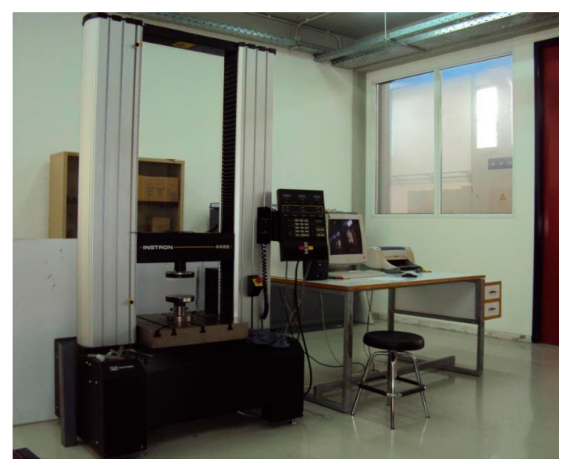
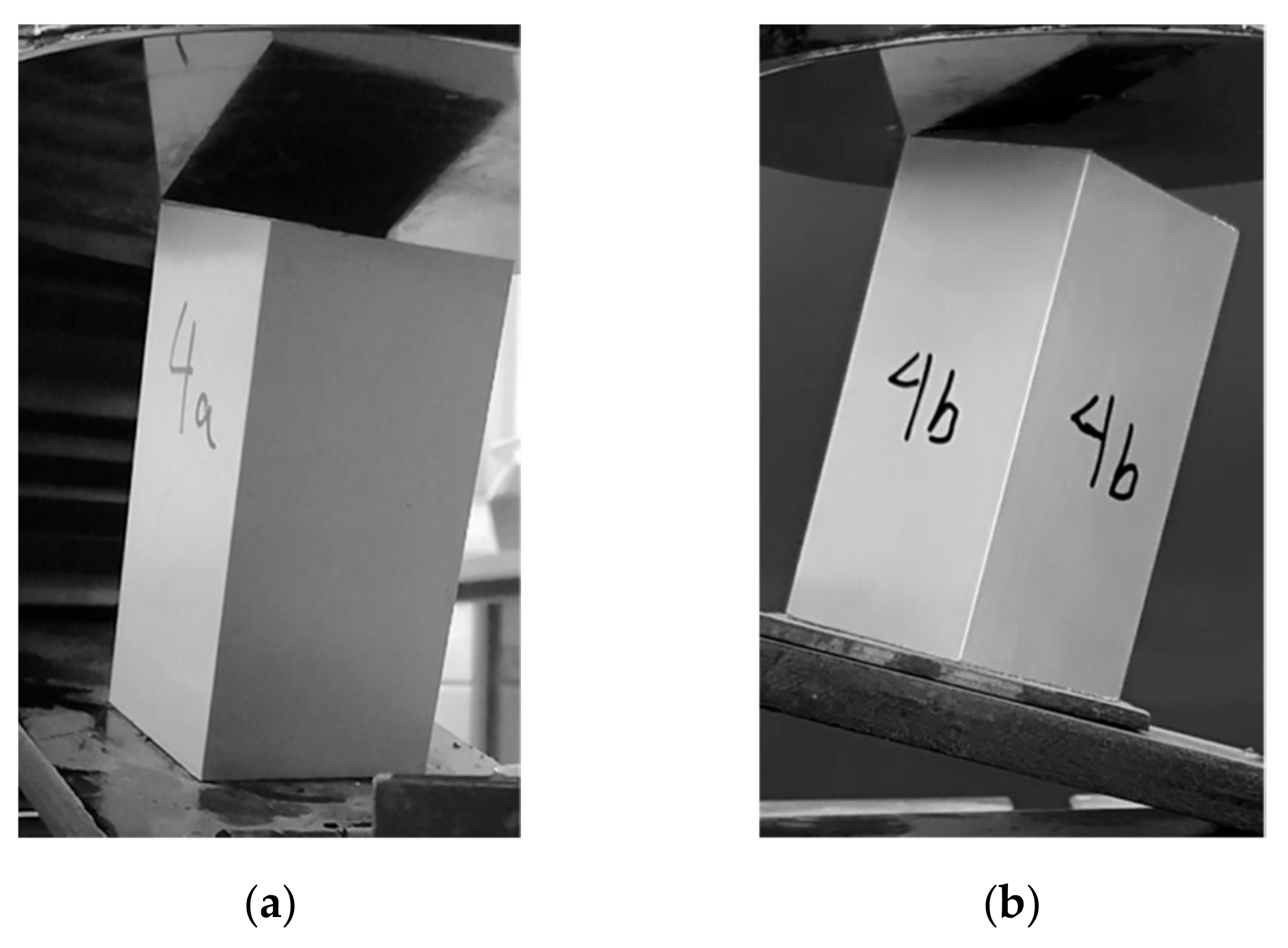
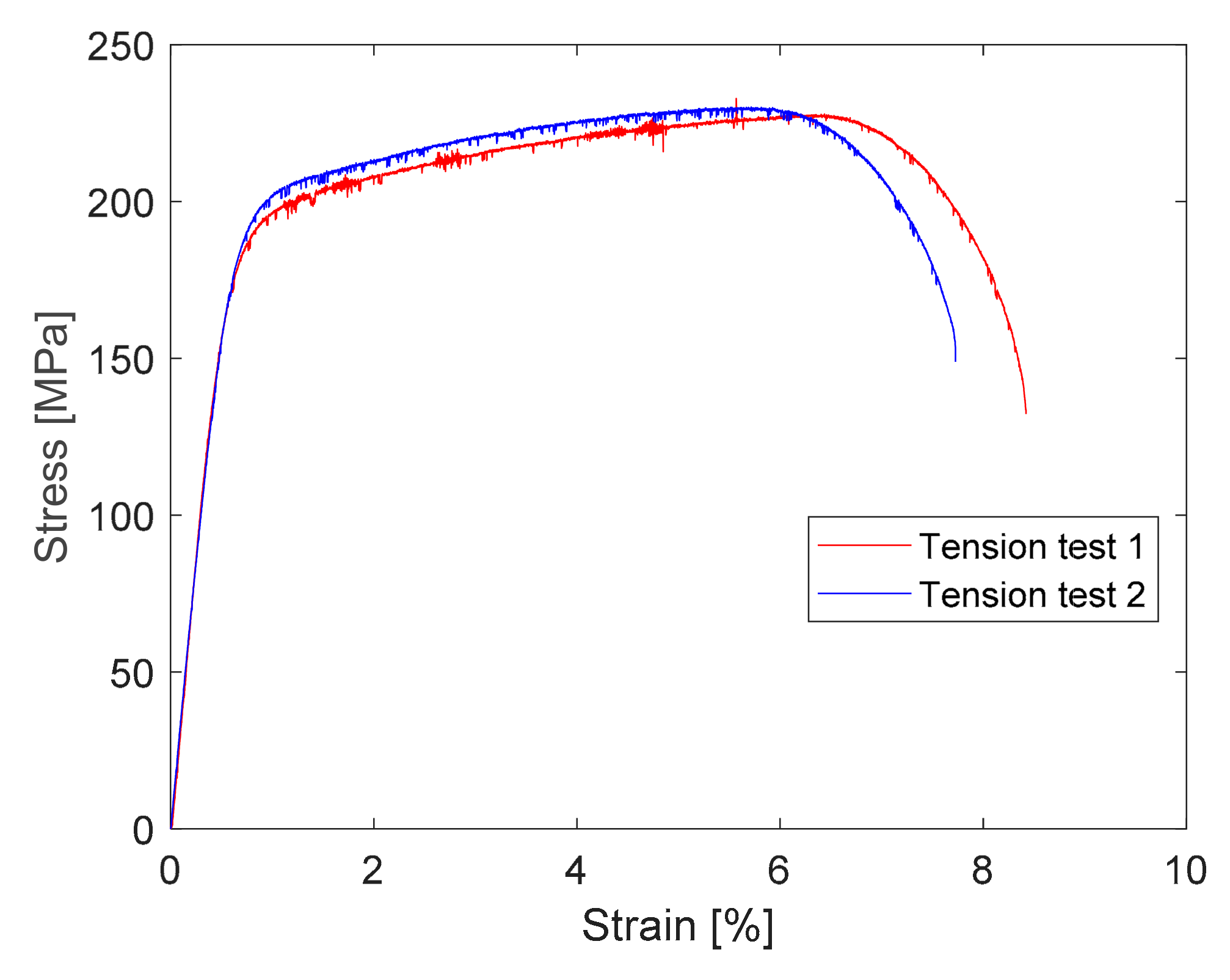
2.2. Material Characterization

The tested aluminum tubes are made of AA6060-T6 subjected to an extrusion process. In order to develop effective numerical models, the mechanical properties and the hardening behavior during plastic deformation of AA6060-T6 tube need to be identified for the material-modeling procedure. For this reason, an experimental tension test is conducted according to ASTM E8M-2004 standards in an INSTRON 4482 testing machine (Instron, Norwood, MA, USA) at room temperature under a loading rate of 10 mm/min. Although numerical simulations are examined under a significantly higher loading rate, representing the crushing conditions, the selected loading rate of the tension test is considered reliable due to the fact that AA6060-T6 has been proved as lightly sensitive to strain rate [23], and thus it can be modelled as rate-insensitive with good accuracy.
In addition, the tension test is conducted twice in order to avoid any possible material defects or data recording mismatches securing thus the validity of the provided results. Figure 3 depicts the stress–strain curve of AA6060-T6 as revealed from the processing of the measured force and recorded displacement data. Finally, the material mechanical properties such as density, Poisson ratio, and Young’s modulus are estimated according to open literature data, while yield stress, ultimate stress, plastic strain failure, and the stress-plastic strain hardening curve are extracted from the provided tension test curves as summarized at Table 1 and Table 2.

2.3. Quasi-Static Compression Tests

All experimental compression tests were conducted in an INSTRON 4482 dual-column testing machine (Instron, Norwood, MA, USA) under quasi-static conditions of 10 mm/min loading rate. In all test cases, the maximum specimen shortening reached about 60 mm, while in the case of oblique loading, the tube and the bottom holder were rotated to the proper angle, representing off-axis oblique loading conditions. Furthermore, in the case of oblique loading, the bottom tube end was fixedly supported to the bottom holder in order to avoid any sliding during plastic collapse. For each experimental test, a proper data recording system was utilized for force (F) and displacement (x) measurements in order to provide the respective experimental F-x curve, which is taken into consideration for both crashworthiness performance evaluation of the examined tubes and the validating procedure of the developed finite element models. Moreover, different states of plastic collapse are captured during the specimen-deformation process in order to identify the failure mechanism occurring and its formation characteristics. Finally, the experimental results regarding crashworthiness response parameters and collapse mode are set into comparison with the numerical results for validating the accuracy of the developed models, although the examined strain rate of quasi-static tests and FEA simulations differ from each other, as AA6060-T6 has been described as strain-rate insensitive with sufficient accuracy [23].

2.4. Crashworthiness Response Parameters

This study utilizes several widely used crashworthiness response parameters regarding energy-absorption capacity, plastic collapse initiation, and crushing efficiency in order to evaluate the crashworthiness performance of the examined tubes. The energy-absorption mechanism of thin-walled tubes contains the bending energy, which is dissipated by the bending of rotated folds and the membrane energy, which in turn is dissipated by the extension of formulated plastic folds [24]. In more specificity, the utilized crashworthiness indicators include peak crushing force (PCF), mean crushing force (MCF), energy absorption (EA), specific energy absorption (SEA), and crushing force efficiency (CFE). The assessment of the above crashworthiness response parameters is carried out via the provided force-displacement curves.
EA refers to total energy absorption, which is dissipated during plastic collapse as the crushing kinetic energy is transformed into plastic deformation energy. Considering F(x) as the instantaneous crushing force and d as the maximum impactor displacement, EA is computed as the total area below the force-displacement curve as depicted in the following:
E A = 0 d F x dx
However, a more reliable indicator for assessing the energy-absorption capacity of structures is SEA, which expresses the absorbed energy per unit mass of the crushed structure (m). Thus, SEA reflects a more indicative parameter than EA for comparing the crashworthiness performance for structures of different material, dimensions, and cross-section geometry. Thus, for a crushed structure of ρ material density, A cross-sectional area, and d maximum crushing shortening, SEA is expressed as follows:
S E A = E A m = E A ρ · A · d
Regarding the crushing force indicators, PCF and MCF contain the two metrics, which reflect the plastic collapse initiation and the energy-absorption capacity, respectively. In more detail, PCF refers to maximum crushing force required for plastic collapse initiation and is responsible for the initial formulation of the first plastic convolution, while MCF is defined as the ratio of energy absorption to the maximum impactor displacement. In fact, MCF represents a constant sustained force during post-buckling region of force-displacement curve in which the plastic collapse progresses, formulating local force peaks and lows reflecting the formulation of external and internal folds, respectively. Thus, PCF and MCF can be expressed, respectively, as:
P C F = max   F x
M C F = E A d
Finally, CFE is defined as the ratio of MCF to PCF where MCF reflects the mean sustained force under which the plastic collapse progresses by folding deformation. Thus, considering PCF as the maximum crushing force, the CFE parameter reflects the uniformity of crushing force fluctuation and is expressed as:
C F E = M C F P C F
Thus, the desirable characteristics of an efficient energy absorber include high enough EA and SEA revealing a sufficiently high energy-absorption capability under low weight. Similarly, high MCF will allow for high EA levels, while PCF must be sufficiently high to allow for high crushing-force levels, restricted however by a reasonable upper limit, which must be reached by the crushing force in order to deform plastically the crushed structure, as in the opposite case the level of absorbed energy will be negligible due to inelastic deformation.

2.5. Finite Element Modeling

For the crashworthiness response evaluation of the examined tubes, numerical simulations are also carried out utilizing non-linear explicit dynamic LS-DYNA code [25] as the modeling tool in this study. Finite element (FE) models are developed for the examined cases of axial and oblique impact loading in order to investigate the crashworthiness behavior and capture the effect of crushing angle and initial type of contact between tube and impactor. Therefore, for each simulated oblique impact loading case, two different FE models are created, representing each examined initial contact type between impactor and tube, as Figure 4 depicts regarding edged and cornered oblique crushing conditions. For the development of the FE models, the geometry and the dimensions are initially defined regarding the parts from which the tested configuration consists of, including the tube specimen, bottom holder, and impactor. Next, an element mesh is generated, selecting the type of finite elements and the mesh density, while following this the material properties are adjusted properly. After this, the boundary conditions are defined regarding the tube-end support, constraining properly its nodal degrees of freedom (DOFs), while also boundary conditions for avoiding any penetration phenomena are considered for the interface contacts. The modeling procedure is completed by determining the loading characteristics and the time termination.
More specifically, thin-walled tested tubes are modelled via four-node shell elements as their accuracy in predicting the failure mechanism regarding the collapse mode and the number of formulated folds has been proved more reliable than others in the case of thin-walled structures [26]. In contrast, impactor and bottom-holder base are modelled via eight-node solid elements, as they are treated as compact rigid bodies. In addition, the shell element tubular square cross-section is dimensioned according to its mean circumference, with a width of 48.5 mm, while the finite element mesh density is generated properly, such that the shell element dimensions are adjusted at 1.5 × 1.5 mm, as a dimensioning just about equal to the tube-wall thickness provides reliable results regarding the fold formulation of thin-walled structures [27]. Further, for the shell element formulation, the Belytschko–Lin–Tsay formula with five integration points through shell thickness is considered. The proposed element formulation model is based on the Reissner–Mindlin kinematic assumption [28], which takes into account the superposition of mid-surface displacements and rotations to express plate deformation, considered as thus more suitable for shell elements. Additionally, a viscous and stiffness hourglass control is adjusted according to the Flanagan–Belytschko stiffness formula under an hourglass coefficient of 0.1, thus avoiding an hourglass formation of elements, which results in zero energy-deformation modes and volumetric blocking [7], which could bring instabilities during numerical solution.
For the material modeling, the AA6060-T6 tube material is approached via an isotropic elastic-plastic model utilizing the ‘Mat024 piecewise linear plasticity’ keyword of LS-DYNA, which is capable of capturing AA6060-T6 linearly hardening behavior sufficiently. In specific, the ‘Mat024′ keyword utilizes the material properties such as density, Poisson ratio, and Young’s modulus, which are introduced according to the data listed in Table 1, and considers further AA6060-T6’s linear hardening behavior, which is identified by a number of stress-plastic strain points, according to the results from the AA6060-T6 tension test in Table 2. In addition, the ‘Mat024′ model is capable of accounting for failure criteria and the strain-rate effect [24], which however is not implemented in this study, as AA6060-T6 has been described as strain-rate insensitive [23] with sufficient accuracy. In contrast, a failure plastic strain of 7.93% according to Table 1’s results is implemented during FE material modeling in order to capture the tearing failure around tube corners during their plastic collapse, as revealed in some of the experimental tests. Thus, this study considers aluminum-tube hardening behavior with only the effect of plastic strain implementing in addition a failure plastic strain penalty. Regarding the steel plates of the impactor and bottom holder base, the ‘Mat020 rigid’ keyword is utilized as both impactor and bottom base are of significantly higher mass and stiffness and are considered thus as undeformable and rigid bodies. For ‘Mat020′ model of impactor and bottom holder, steel material properties are considered, such as 7830 kg/m3 density, 200 GPa Young’s modulus and a Poisson ration of 0.3, while for each body the kinematic DOFs are also adjusted properly, allowing only a vertical displacement for impactor and constraining each kinematic DOF for the bottom holder base, which is stationary during the test.
Following this, the boundary conditions for the interface contacts are implemented in order to prevent from any penetration between the interacting structural members. Thus, at first a ‘nodes-to-surface’ contact algorithm between tube and rigid bodies of impactor and holder base is adjusted in order to avoid any penetration of the nodes of the tube shell elements with the surface of the impactor and bottom base. The ‘nodes-to-surface’ contact algorithm implements a penalty formulation that allows the separate definition of the tube slave nodes and the master contacting surfaces of rigid impactor and base, thus preventing any penetration in the interfaces. Additionally, Coulomb friction conditions are considered by applying static and dynamic friction coefficients of 0.61 and 0.47, respectively, according to open literature data for aluminum–steel interface contacts. In addition, an ‘automatic single surface’ contact algorithm is further implemented to detect self-interaction of tube shell elements contacting each other during the formulation of folds, as the plastic collapse progresses. For this reason, shell elements’ nodal normal projections are used by the ‘automatic single surface’ algorithm in order to prevent tube elements from penetrating the specimen surface. Coulomb friction static and dynamic coefficients are adjusted to equal 1.2 and 1.4, respectively, according to open literature data for aluminum–aluminum interface contacts. More, boundary conditions regarding the fixed bottom tube end are also adjusted, constraining the bottom tube nodal DOFs against any displacement and rotation.
Completing the FE-modeling procedure, the loading characteristics of each examined test case are simulated by applying a constant loading rate of 1 m/s until 60 mm of maximum impactor vertical displacement, while the examined crushing angle is implemented by rotating tube and bottom holder base to the proper angle. The significantly higher loading rate of FEA simulations compared to that of quasi-static tests is not only due to the strain-rate insensitivity of AA6060-T6, but also mainly due to the fact that the explicit time integration method, which is utilized during numerical solution, requires a reasonable time step, revealing thus simultaneously reliable results and avoiding extremely large calculation times. Finally, a time step of 1 ms is adjusted for recording the force-displacement data and the collapse states of the FEA simulations.

3. Results and Discussion

3.1. Modeling Verification

At first, a comparison between experiments and FE models was carried out in order to secure the validity of the developed models for accounting for both numerical and experimental results (Table 3) in the evaluation of the crashworthiness performance of the square tubes in terms of energy-absorption capacity and plastic collapse initiation. Thus, both tests and simulations showed a sufficient agreement in crushing force fluctuation during collapse, as the respective force-displacement curves depict in all examined cases shown in Figure 5, Figure 6, Figure 7 and Figure 8. As a result, a sufficient agreement in the predicted PCF and EA was revealed too, providing deviations between tests and simulations below 7.6% and 6.8%, respectively, as Table 4 depicts.
Further, simulations seemed to capture sufficiently the plastic collapse mechanisms that occurred in tests, as Figure 9, Figure 10, Figure 11, Figure 12, Figure 13, Figure 14 and Figure 15 depict, predicting both the collapse mode and the number of formulated folds in most cases, which is additionally reflected by the number of local peaks and lows in crushing-force fluctuation during impactor displacement. More specifically, for an axially crushed tube, the test showed an inextensional deformation mode with three formulated folds during collapse, while tearing failure was also observed around tube corners, due to the high bending-moment concentration. In similar direction, the simulation revealed a mixed collapse mode, showing two initial extensional folds and one inextensional fold at following, predicting in addition the occurrence of tearing around tube corners. Moreover, for 5° and 10° obliquely crushed tubes either under an edged or a cornered initial contact with the impactor, both tests and simulations revealed three inextensional folds during plastic deformation; however, the slight tearing around tube corners in tests was not captured by simulations due to a lower PCF, which was not proved to be great enough to react to material failure, due to stress concentration in the tube corners. Finally, regarding 15° obliquely crushed tubes under either an initial contact with the impactor on an edge or in a corner, both simulations and tests agreed on an inextensional deformation mode during collapse, formulating two folds, while the slight tearing failure observed in tests was not captured by simulations as was achieved in the axial impact loading case. Therefore, all simulations showed a sufficient agreement with the experiments regarding both the collapse mechanism and the number of formulated folds, while tearing failure was only captured in axial impact loading, as the in the case of obliquely crushed tubes the tearing extent was significantly lower without thus affecting the energy-absorption capacity, which was predicted with sufficient accuracy by FE models.

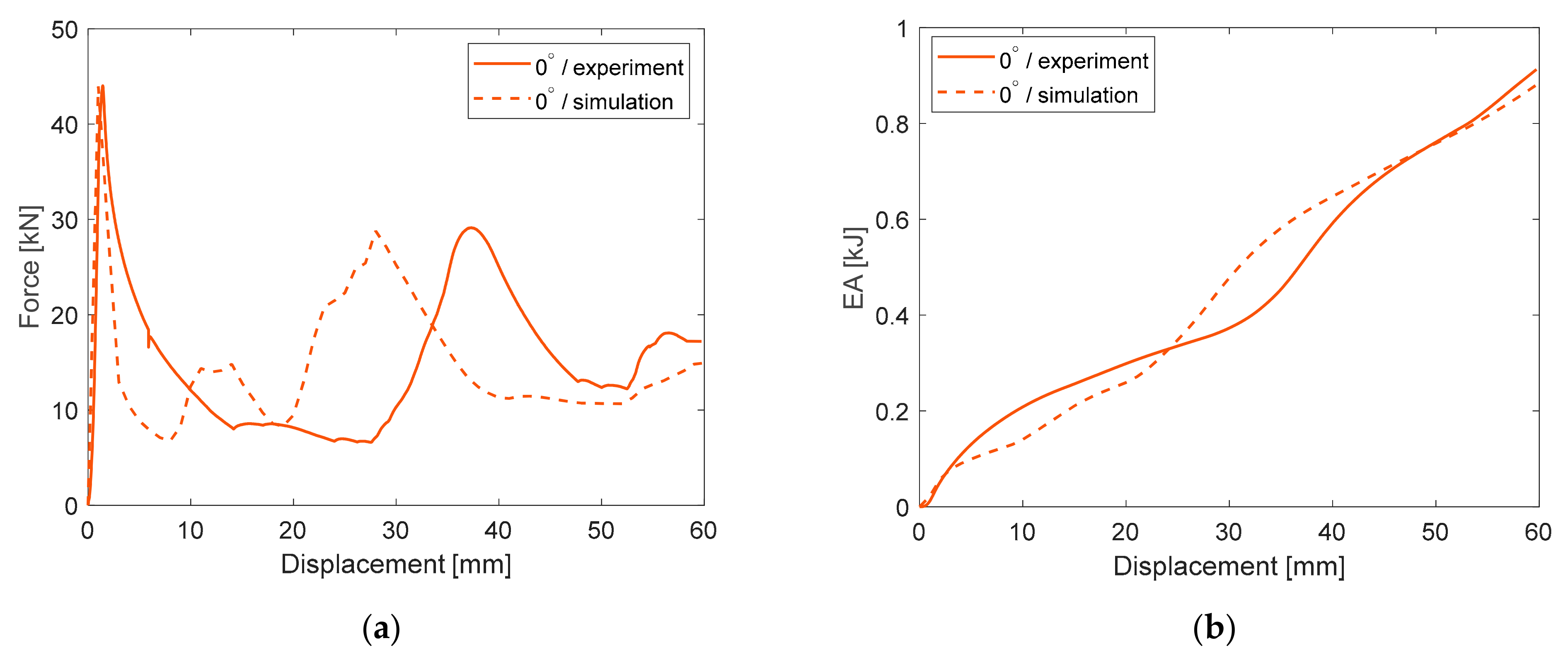
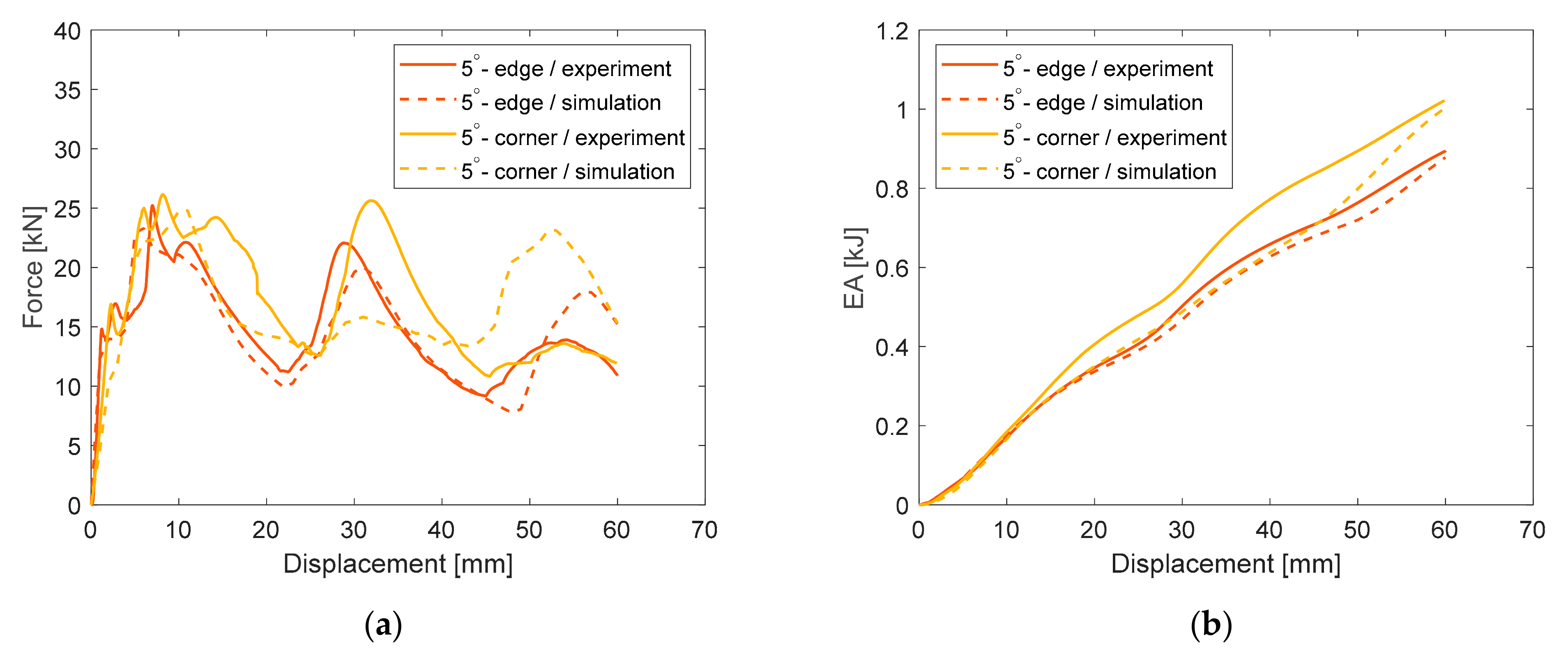
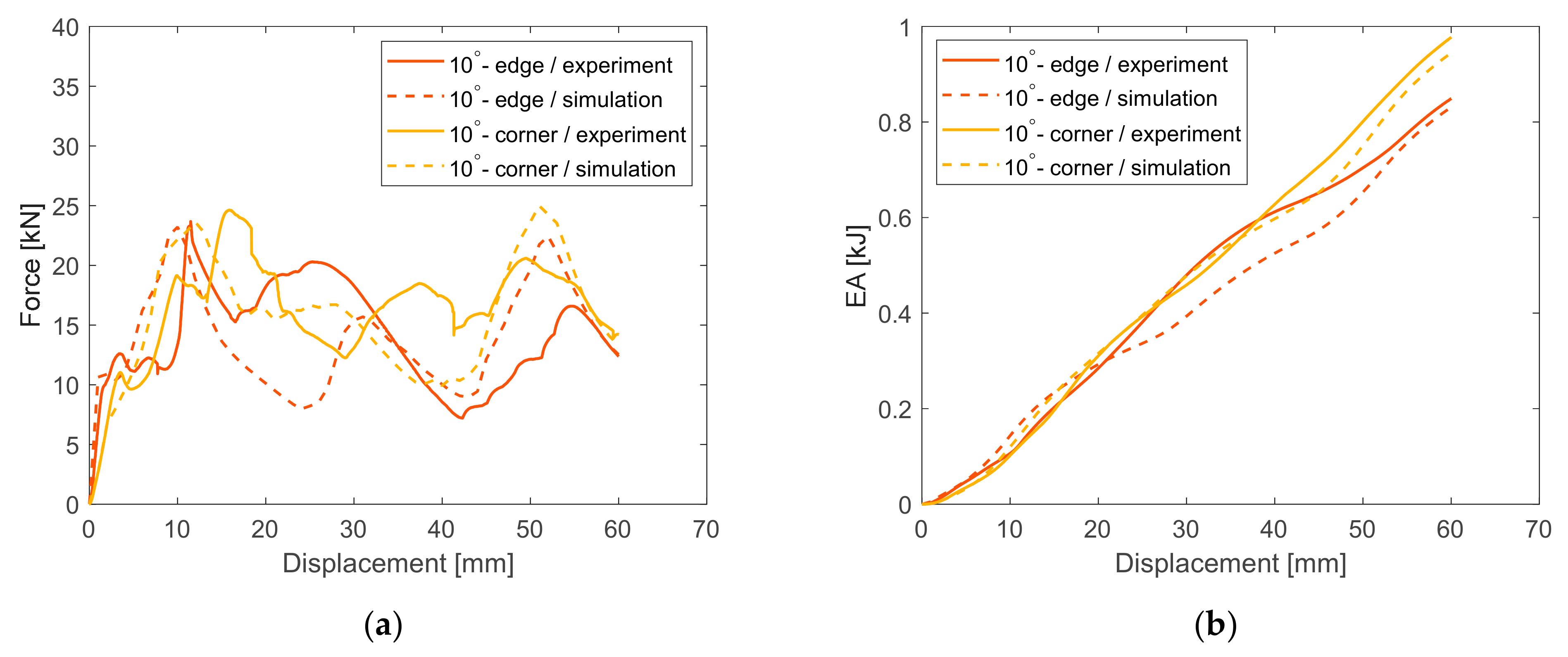
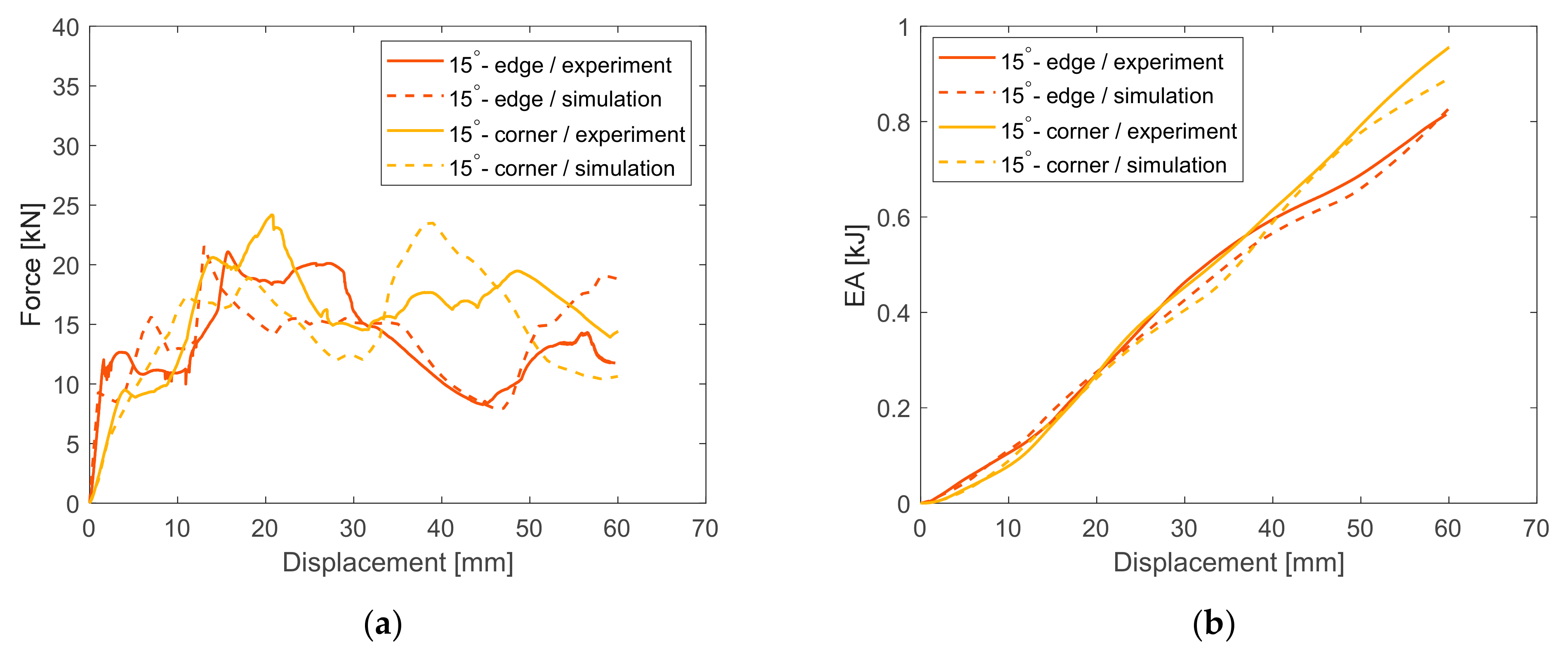
3.2. Force-Displacement Characteristics

For the evaluation of crashworthiness performance, force-displacement and EA-displacement curves are provided regarding both experimental and numerical results as Figure 5, Figure 6, Figure 7 and Figure 8 depict. Thus, the proper crashworthiness indicators are estimated in order to assess the energy-absorption capacity and the plastic collapse initiation regarding the examined loading cases. In more specificity, the plastic collapse initiation of axially crushed tubes occurred around 44 kN, formulating the first plastic fold, while at the next, two more folds were deformed as reflected by the local peaks and lows in crushing force, the fluctuation of which was sustained around an MCF of 15 kN during collapse. In fact, tearing failure was also observed around tube corners due to high stress concentration, which is captured by the drop in the rate of EA increase during impactor displacement range from 20 mm to 40 mm as shown in Figure 5b. That decrease in the rate of EA increase is caused by the unstable behavior of tearing failure, which was predicted slightly earlier during collapse progress by the FE model compared to the experiment. For this reason, a deviation between experiment and simulation is provided regarding the displacement region in which the EA slope reduction occurred in Figure 5b, where the tearing failure is predicted at a lower displacement by the FE model.
For the 5° obliquely crushed tube, regarding the initial contact in the edge case between impactor and tube, the plastic collapse initiation was revealed around 24 kN, while the force fluctuation during collapse was sustained around 14.8 kN, formulating three local peaks and lows of crushing force, reflecting the deformation of three inextensional plastic folds. Further, the slight tube tearing that occurred did not seem enough to react to any significant EA decrease, as its increase rate during collapse seems to be almost constant, as Figure 6b depicts. However, the 5° crushing angle reacted to both PCF and EA decrease, due to the additional bending moment introduced by the lateral crushing-force component, thus facilitating both plastic collapse initiation and progress, as less bending energy was required for the formulation of plastic folds. Regarding the 5° obliquely crushed tube under an initial contact with the impactor on a corner, a PCF of 25 kN revealed the plastic collapse initiation, and also revealed a progressive behavior, with three inextensional folds reflected by the crushing-force distribution around 17 kN MCF. Despite the angled loading, the 5° cornered oblique crushing revealed greater energy-absorption capacity compared to both 5° edged loading and axial impact, as the tearing failure was of a significantly lower extent, which in the case of the axially collapsed tube reacted to an important decrease in EA.
The 10° obliquely crushed tube under an initial edge contact with the impactor, revealed a PCF of 23.5 kN while MCF was sustained about 14 kN reflecting the formulation of three plastic folds during collapse, as depicted by the local force peaks in force-displacement curve in Figure 7a. The greater crushing angle of 10° compared to previous cases reacted to lower PCF, while further energy-absorption capability revealed a decrease too as the angled loading introduced an additional bending moment, which facilitated the plastic fold deformation and thus plastic collapse initiation and progress. In the case of the 10° obliquely crushed tube with an initial corner contact with impactor, PCF and MCF were captured at about 24.8 kN and 16 kN, respectively, revealing a PCF drop due to the increased crushing angle compared to axial and 5° oblique impact. However, the EA seemed to be greater compared to the 10° oblique edged loading due to the cornered initial contact and slighter tearing extent, which is reflected in Figure 7b, where EA increases linearly during collapse under a more constant slope compared to that of the edged oblique loading. However, both PCF and EA revealed a slight decrease compared to 5° oblique loading for both edged and cornered initial contact types, due to the higher crushing angle.
Finally, the 15° obliquely crushed tube under an edged initial contact with the impactor revealed a PCF of 21.2 kN, reflecting a plastic collapse initiation, while MCF was captured about 13.7 kN reflecting the lowest energy-absorption capacity among all examined cases due to the crushing angle effect, which reduced EA with loading angle increase. The occurrence of slight tearing failure resulted in only a slight drop in the rate of EA increase during the final stages of collapse, as captured in Figure 8b by the reduced EA curve slope. However, regarding the 15° cornered oblique impact case, PCF and EA were at greater levels due to the cornered contact between tube and impactor, which introduced a lower bending moment due to the angled loading compared to the edged oblique crushing. As a result, EA increased linearly at a greater rate compared to the edged oblique loading.

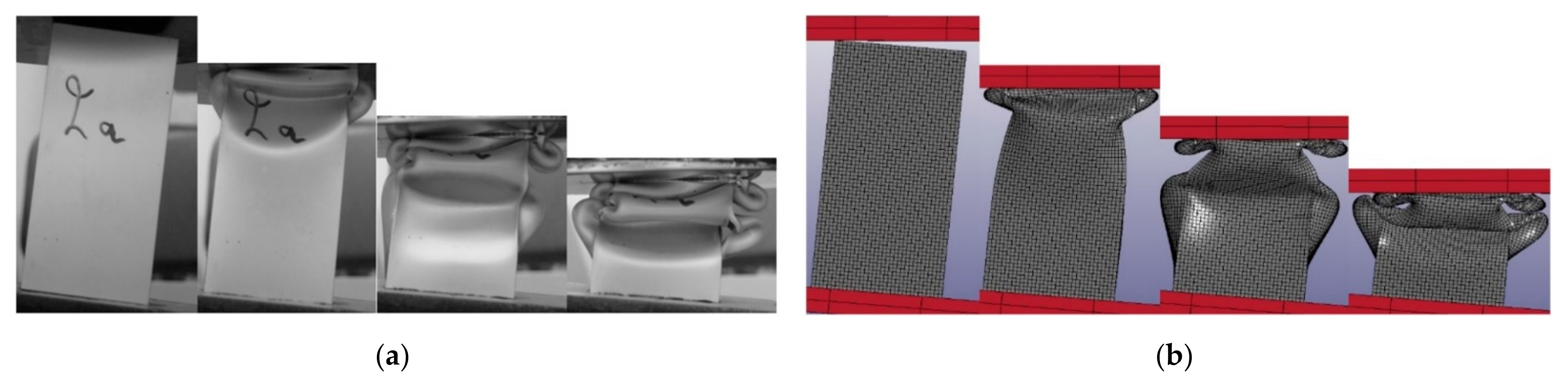
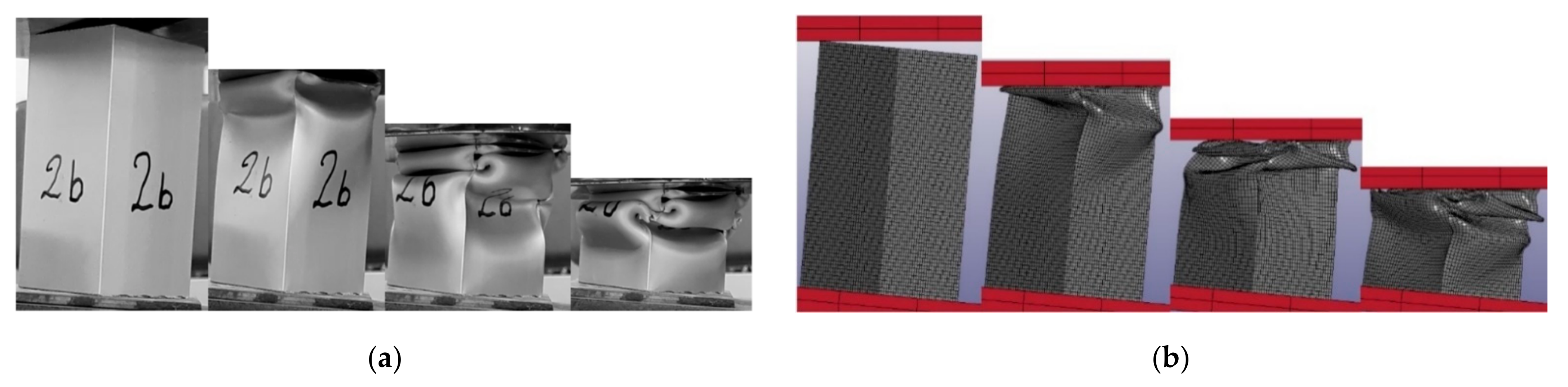
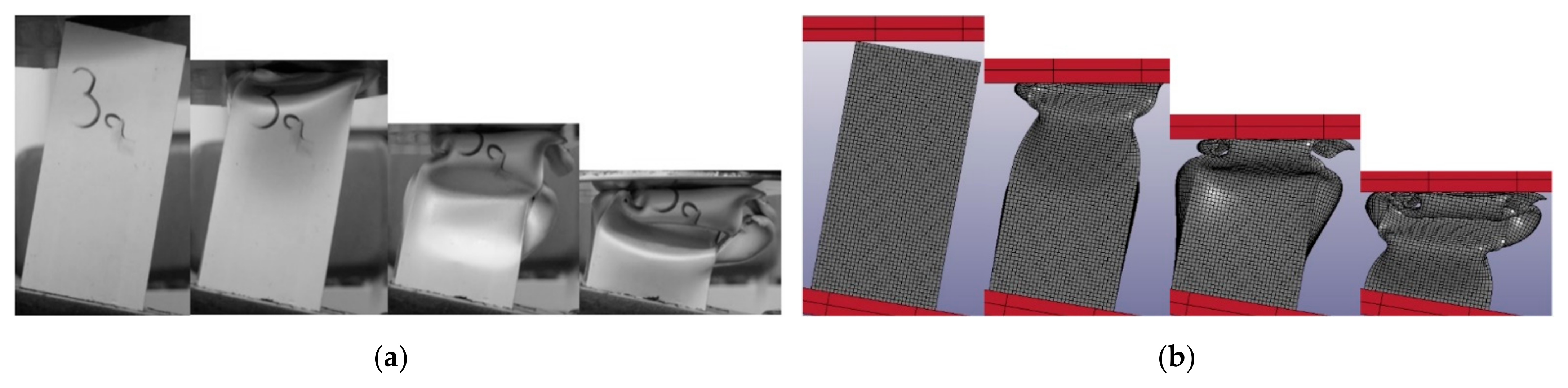
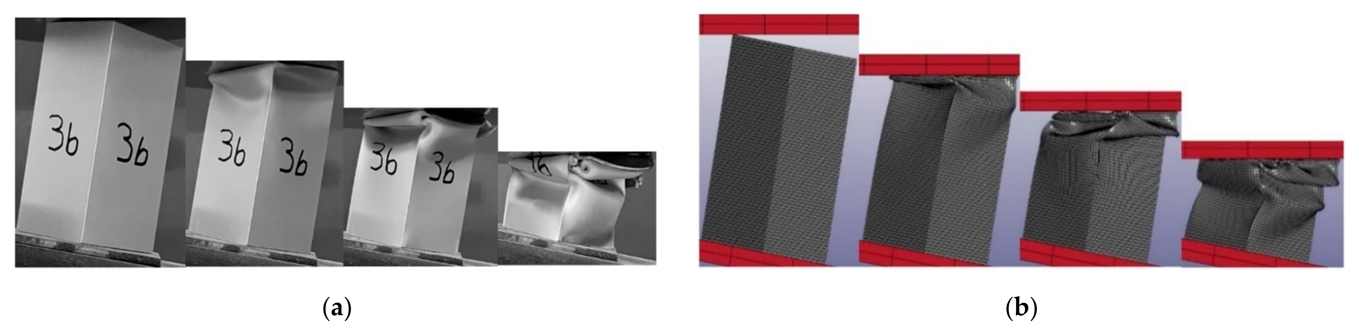
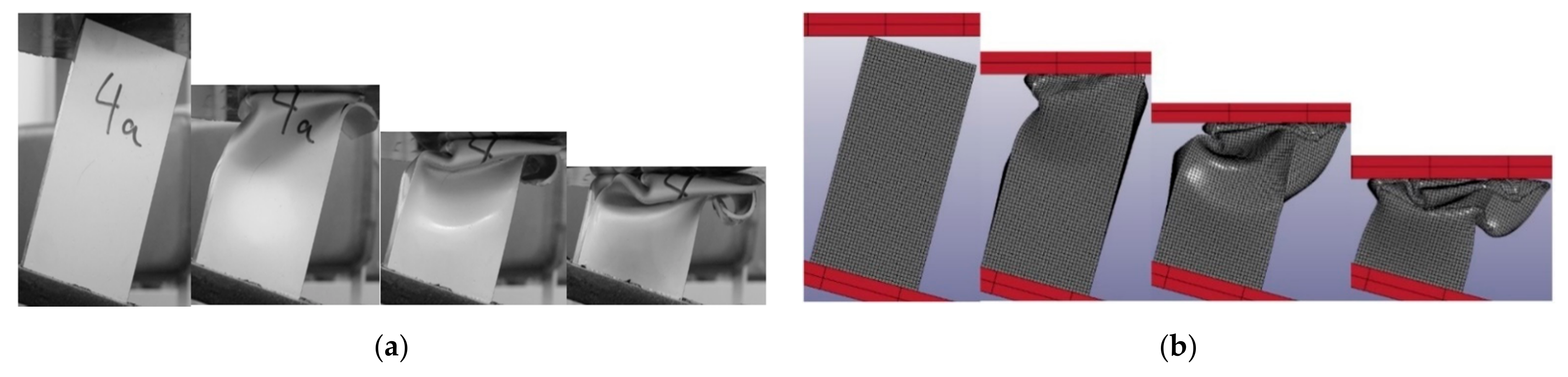
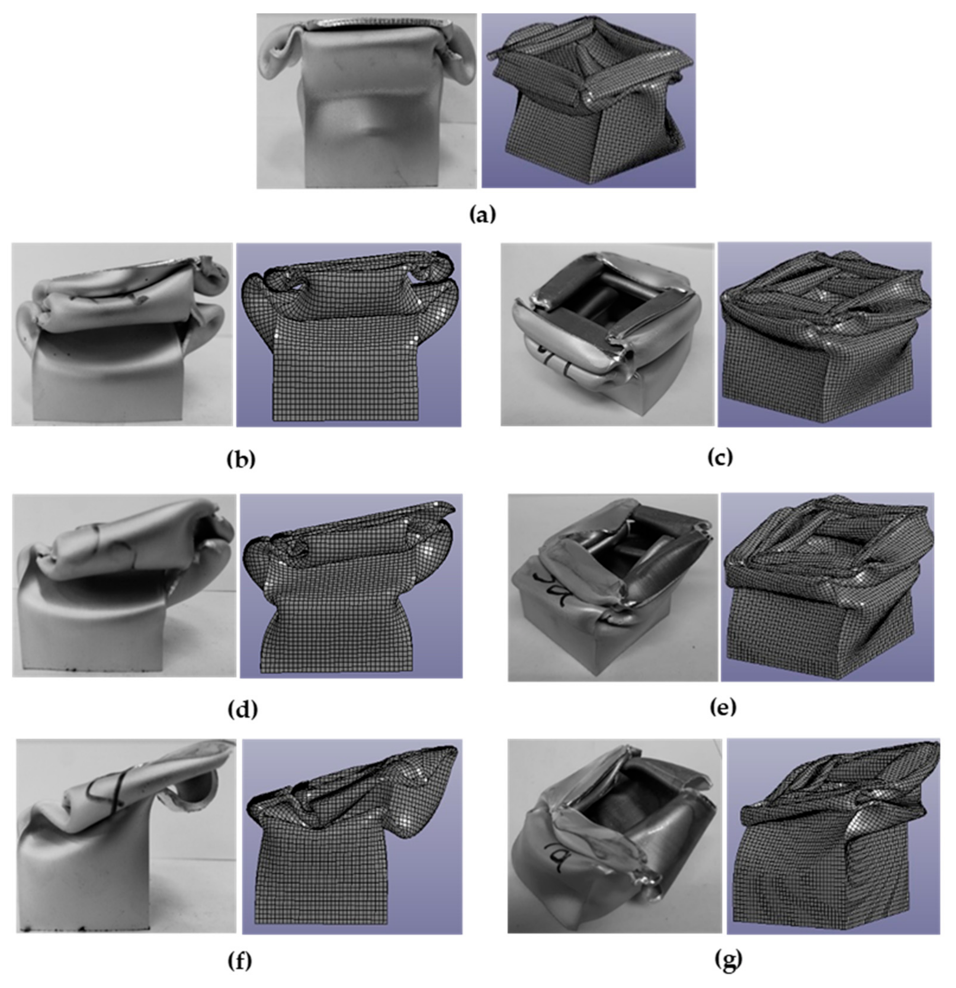
3.3. Deformation Modes

The plastic collapse mode is also investigated by evaluating the observations of both experiments and simulations by capturing different states of collapse shown in Figure 9, Figure 10, Figure 11, Figure 12, Figure 13, Figure 14 and Figure 15 for all examined cases. The importance of analyzing the failure mechanism that occurred is its effect on the crushing force fluctuation during plastic deformation, as the local peaks and lows in crushing force reflect the formulation of external and internal plastic folds, respectively. Thus, the mode of collapse mechanism affects further the energy-absorption capacity of a crushed structure and for this reason it is considered an additional indicator of crashworthiness performance in terms of a progressive and stable collapse, which will allow for high EA levels. As Figure 9 depicts, the axially crushed tube revealed three plastic folds during collapse, while tearing failure also occurred around the tube corners due to the high stress concentration. In fact, the experiment showed three inextensional folds in contrast with the FE simulation, which in turn revealed a mixed collapse mode by initially formulating two extensional folds and one inextensional fold. The tearing failure reacted to the EA decrease as its rate of increase dropped slightly due to the unstable behavior of the tearing mechanism.
Both 5° and 10° obliquely crushed tubes under either an edged or a cornered initial contact with impactor revealed three inextensional folds during their collapse, in which both experiments and simulation showed an absolute agreement. Further, slight tearing failure was captured in the experimental observations, the low extent of which did not seem to affect significantly the energy-absorption capability, as EA showed a constant increase rate during the collapse affected by the stable and progressive behavior of inextensional folding deformation.
Moreover, 15° obliquely crushed tube formulated two inextensional folds during plastic collapse under both edged and cornered initial contact with impactor. Further, the experiments revealed slight tearing around tube corners, which however was restricted in low extent without so affecting significantly both failure stability and energy-absorption capacity in consequence. Therefore, all examined crushed tubes revealed an inextensional collapse mode formulating three plastic folds except the 15° crushed tubes, which deformed under two folds, while further slight tearing failure was observed around tube corners, which however was captured from the FE model only in the case of axial impact.
The inextensional folding deformation was caused by the non-uniform circumferential distribution of the bending moment, which reacted to a stretching and a compression of the cross-section in different directions, thus causing the formulation of rectangular convolutions during plastic deformation. More specifically, as Figure 16 depicts, for the case of 10° edged oblique crushing, the formulation of inextensional folds is caused by the circumferentially non-uniform resultant bending moments Mx and My, which lead to either external or internal buckling on the cross-section sides depending on their sign. Finally, as Figure 17 shows, the inextensional folding mode was revealed in all crushed tubes, showing in fact a significant superiority against the slight tearing failure occurring around tube corners, thus providing high EA capacity due to its stable and progressive collapse.

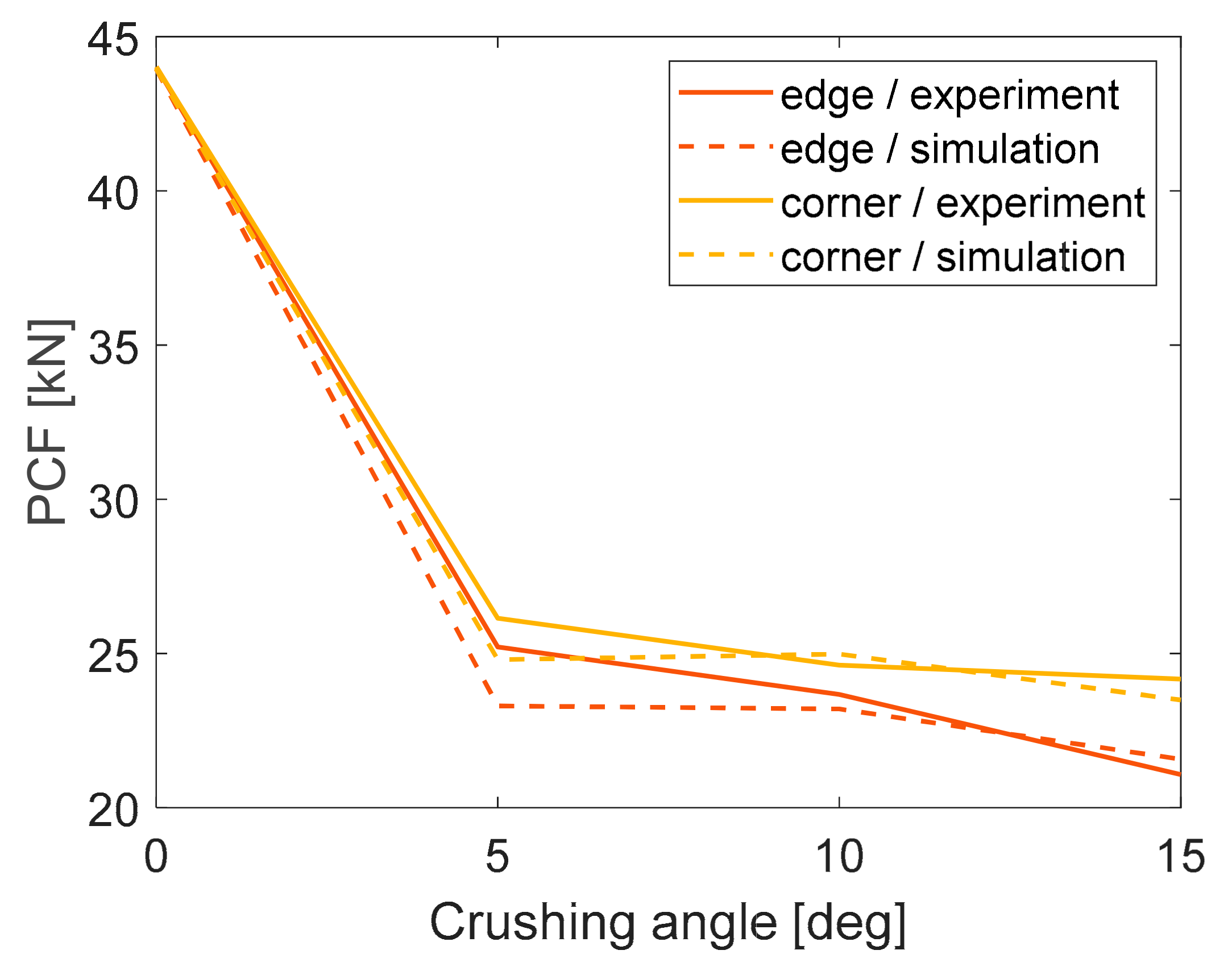
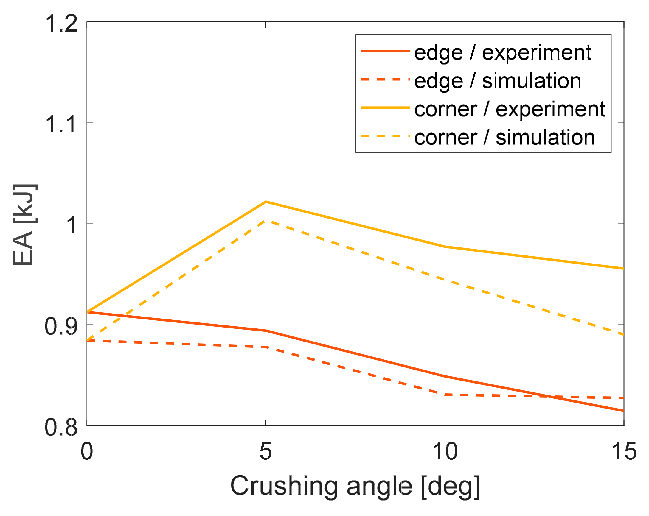
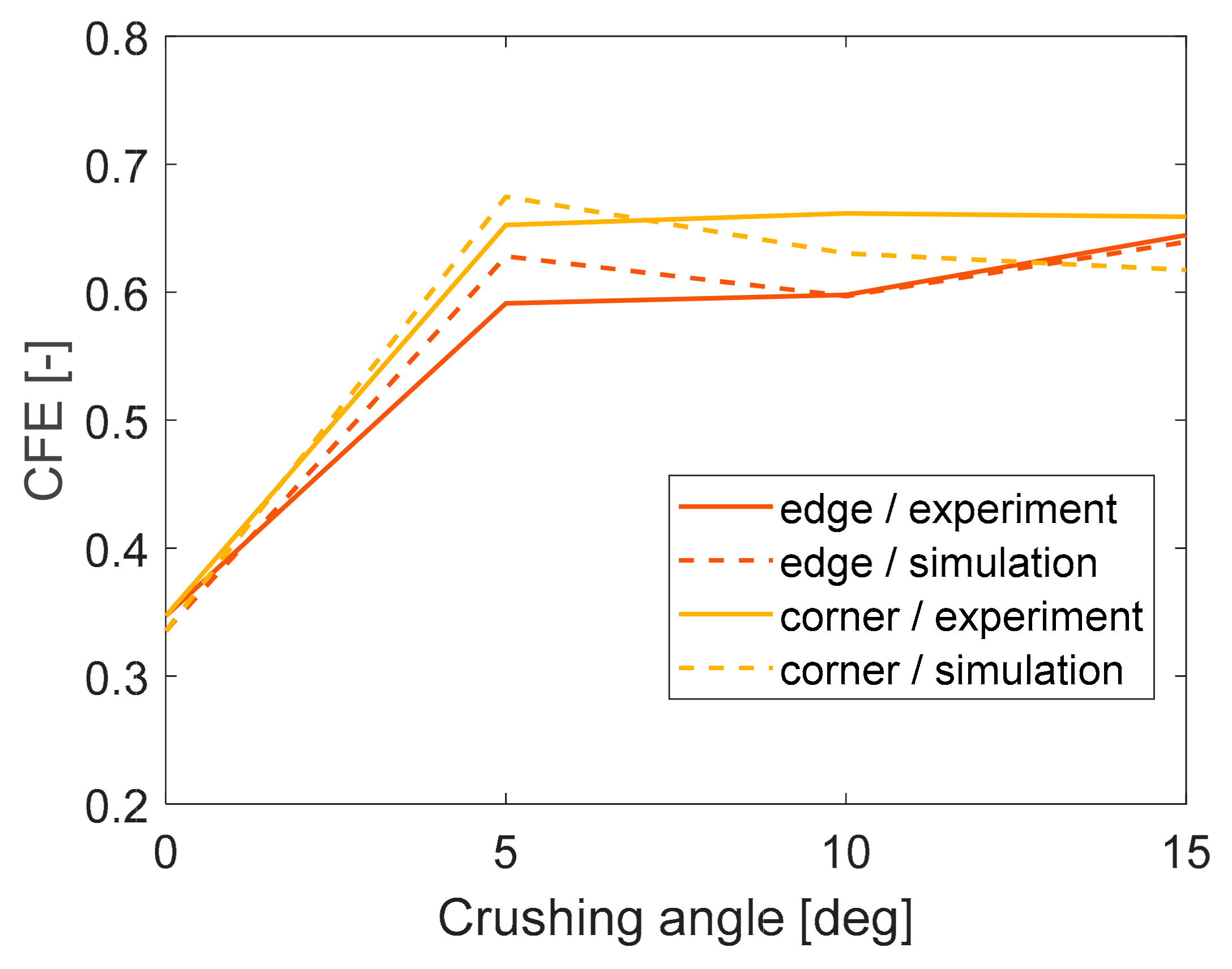
3.4. Crushing Angle Effect

Both numerical and experimental results agreed on the effect of crushing angle on crashworthiness performance in terms of plastic collapse initiation and energy-absorption capacity. In more specificity, the increase in crushing angle resulted in a PCF decrease due to the additional bending moment introduced by the lateral force component, which facilitated plastic collapse initiation. Figure 18 depicts the above tendency showing a PCF drop with the crushing angle either for an edge initial contact or a cornered one between tube and impactor. In fact, PCF reveals a significant decrease in oblique impact loading, reducing by about 43% from axial to 5° oblique impact, while at higher angles the PCF drop seems to flatten out under corner contact between impactor and tube in contrast to edged oblique loading in which PCF seems to linearly decrease with crushing angle even at higher angles.
Further, Figure 19 shows that the increase in crushing angle reacted to lower EA, as additional introduced bending moment due to angled loading facilitated the plastic collapse progress by reducing the necessary plastic bending moment required for folding deformation. However, the 5°obliquely crushed tube under an initial corner contact with the impactor revealed the greatest energy-absorption capacity, lying about 1.022 kJ despite the 5° angled loading, as in the case of axial impact loading the significant tearing failure around tube corners resulted in an EA decrease. For this reason, the EA of the axially collapsed tube proved lower compared to the 5° obliquely crushed tube under corner contact in which the tearing occurred to a significantly lesser extent without thus affecting EA, which was maintained sufficiently. However, the case of 5° edged oblique impact revealed slightly lower EA compared to axial impact, as expected due to the greater crushing angle. Therefore, increased crushing angles resulted in EA drop without accounting for any tearing effect as shown more accurately for all examined oblique loading cases, where a tearing effect was observed to a lower extent.
Finally, as Figure 20 illustrates, CFE revealed an increase at low crushing angles for either an edged or a cornered oblique impact compared to axial crushing, as in the case of cornered oblique loading PCF showed a reduction with angle while EA increased due to the absence of significant tearing. Thus, considering MCF as proportional to EA, CFE seemed to be increased at low angles compared to axial impact. Additionally, in the case of edged oblique loading, although both PCF and EA showed a decrease with angle, the drop in PCF seemed stronger than the one of EA and in consequence in MCF, thus revealing a CFE increase also at low crushing angles. Moreover, higher CFE levels were captured for cornered oblique impact compared to the edged one, while the difference between them seemed to decrease at higher angles. In specific, CFE was flattened out with a crushing angle increase according to experiments for cornered oblique impact, while simulations showed a linear drop of CFE with crushing angle. In contrast, a CFE increase was captured at high angles for edged oblique crushing conditions. Therefore, the cornered oblique impact condition under low crushing angles can be evaluated as the most beneficial loading case providing sufficiently low PCF, resulting in lesser tearing failure and achieving high enough EA and CFE levels.

3.5. Initial Contact Effect

The type of initial contact between impactor and tube did not seem to cause differences in the plastic collapse mechanism in terms of deformation mode and number of formulated folds, as all examined cases revealed the same collapse characteristics for either an edged or a cornered oblique impact under a certain crushing angle. Regarding the effect of initial contact on PCF, as Figure 18 depicts for all examined crushing angle range, cornered oblique impact revealed greater PCF compared to edged one, while their difference was captured slightly higher as the crushing angle increased. In fact, PCF seems to flatten out at high crushing angles under an initial corner contact between tube and impactor, while in contrast PCF decreased linearly under edged oblique impact conditions, showing more a sharper drop at angles above 10°. Thus, edged oblique crushing seems to better facilitate plastic collapse initiation, providing lower PCF levels compared to cornered oblique loading.
Further, EA was revealed greater in the case of cornered oblique impact at all examined crushing angle range compared to edged oblique loading providing higher energy capacity for the crushed tubes as shown in Figure 19. In fact, 5° obliquely crushed tube under an initial contact in corner with impactor revealed the greatest EA among all examined cases, even compared to an axially collapsed tube in which the tearing failure reacted to an EA drop. Moreover, the increased EA in the case of cornered oblique impact compared to the edged one is premised on the fact that the additional bending moment (Madd) due to angled loading introduced by the lateral force component (Fl) as Figure 21 shows, is slightly lower compared to the one in the case of edged oblique crushing. Therefore, the required deformation energy for plastic collapse progress is revealed at a slightly greater magnitude for cornered oblique impact, thus resulting in a greater EA for a certain crushing angle. That is because for short tubes and low crushing angles, the deformation energy is mainly reflected by the bending moment (MFc), which is provided by the compressive crushing force component (Fc) and which, combined with Madd, should result in the plastic bending moment Mp required for plastic fold formulation. Therefore, considering MFc as proportional to EA and in consequence considering MCF according to analytical expressions of various past studies [29,30], the EA of a cornered obliquely crushed structure is revealed to be greater compared to that of edged oblique impact, as he is greater than hc according to Equation (8).
M add = F l · h = F · sin α · h
M p = M add + M F c
tan α = b 2 L h e = 2   b 2 L h c
Finally, CFE is also captured at higher levels for cornered oblique crushing conditions compared to edged ones, as in the first case the benefit in EA and in consequence in MCF overcomes the greater observed PCF revealing thus higher CFE. In fact, the maximum CFE is obtained at about 0.675 for the 5° obliquely crushed tube under an initial contact in corner with impactor. Additionally, CFE seems to flatten out at higher angles regarding cornered oblique impact, while edged oblique crushing revealed a CFE increase at higher loading angles, thus reducing the difference in CFE between the two examined types of initial contact at high angles. Therefore, cornered oblique impact under low crushing angles is considered the most beneficial loading scenario resulting in the greatest EA capacity under the highest CFE.

4. Conclusions

This study investigated the crashworthiness behavior of thin-walled aluminum square tubes subjected to both axial and oblique impact, emphasizing the effect of crushing angle and initial contact between tube and impactor on plastic collapse initiation and energy-absorption capability. Two types of initial contact were examined, consisting of an edged and a cornered contact. Both quasi-static tests and FE simulation in LS-DYNA were performed, while the provided experimental and numerical results were compared for the modeling validation and the evaluation of crashworthiness performance.
Both experiments and simulations showed a sufficient agreement on PCF and EA, while the observed collapse mechanism was also captured by the FE models, revealing inextensional folds and predicting their number accurately. However, tearing failure around tube corners was only captured for the axially crushed tube as in the case of obliquely crushed tubes the low extent of the tearing that occurred was not shown by the simulations, as the significantly lower PCF did not seem enough to cause material failure. In more specificity, in all examined cases three inextensional plastic folds were revealed during collapse, except the 15° obliquely crushed tubes, where two inextensional folds were formulated. Additionally, all conducted experiments revealed slight tearing failure around tube corners, which however was of a significantly lower extent in the case of obliquely crushed tubes. The 5° obliquely crushed tube under an initial corner contact with the impactor revealed the greatest EA and CFE reflecting, and thus the most beneficial loading condition for the examined square tubes. Compared to the axially crushed tube, the greater energy capacity of the 5° cornered collapsed tube was revealed mainly due to the lower tearing extent, which in the case of axial impact reacted to the EA drop due to its greater magnitude.
Observing the results regarding oblique impact loading, the increase in crushing angle resulted in PCF drop as the lateral force component reacted to additional bending moment, thus facilitating the plastic collapse initiation. Further, the bending moment due to angled loading resulted in a lower deformation energy required for folding formulation, thus revealing an EA decrease as the crushing angle increased. In specific, however, the effect of tearing failure on EA was proved stronger than that of the crushing angle in low loading angles, thus resulting in a lower EA in the case of axial impact compared to 5° cornered crushing. As a result, CFE was maximized in low crushing angles, while as the angle became higher CFE seemed to flatten out or slightly increase.
Finally, regarding the effect of the initial contact type between impactor and tube, cornered oblique impact revealed the greatest PCF and EA at all examined angle ranges. More specifically, the difference in PCF between edged and cornered oblique collapse was increased at higher crushing angles, as PCF almost flattened out at high angles, while regarding edged oblique impact PCF seemed to linearly decrease with the loading angle. Further, cornered oblique impact reacted to lower bending moment due to the angled loading compared to the edged one, thus revealing significantly greater EA as higher deformation energy was then required for folding formulation. However, the initial contact type between impactor and tube did not seem to affect mechanism of the mode of plastic collapse and the number of formulated folds. CFE was also higher for an initial corner contact between the impactor and tube, while the difference in CFE compared to edged oblique loading was decreased at higher angles. Therefore, cornered oblique impact under a low crushing angle was proved to be the most beneficial loading case, providing the greatest EA and CFE between all examined cases.

Author Contributions

Conceptualization, K.D.K. and D.E.M.; methodology, K.D.K.; software, K.D.K.; validation, K.D.K.; formal analysis, K.D.K.; investigation, K.D.K.; resources, K.D.K. and D.E.M.; data curation, K.D.K.; writing—original draft preparation, K.D.K.; writing—review and editing, K.D.K.; visualization, K.D.K.; supervision, D.E.M.; project administration, D.E.M.; funding acquisition, D.E.M. All authors have read and agreed to the published version of the manuscript.

Funding

This research received no external funding.

Institutional Review Board Statement

Not applicable.

Informed Consent Statement

Not applicable.

Data Availability Statement

Not applicable.

Conflicts of Interest

The authors declare no conflict of interest.

References

  1. Pei, T.S.; Saffe, S.N.M.; Rusdan, S.A.; Hamran, N.N.N. Oblique impact on crashworthiness: Review. Int. J. Eng. Technol. Sci. 2017, 4, 32–48. [Google Scholar] [CrossRef]
  2. Kim, H.S.; Wierzbicki, T. Numerical and analytical study on deep biaxial bending collapse of thin-walled beams. Int. J. Mech. Sci. 2000, 42, 1947–1970. [Google Scholar] [CrossRef]
  3. Reyes, A.; Langseth, M.; Hopperstad, O.S. Crashworthiness of aluminum extrusions subjected to oblique loading: Experiments and numerical analyses. Int. J. Mech. Sci. 2002, 44, 1965–1984. [Google Scholar] [CrossRef]
  4. Han, D.C.; Park, S.H. Collapse behavior of square thin-walled columns subjected to oblique loads. Thin-Walled Struct. 1999, 35, 167–184. [Google Scholar] [CrossRef]
  5. Tran, T.; Hou, S.; Han, X.; Nguyen, N.; Chau, M. Theoretical prediction and crashworthiness optimization of multi-cell square tubes under oblique impact loading. Int. J. Mech. Sci. 2014, 89, 177–193. [Google Scholar] [CrossRef]
  6. Pirmohammad, S.; Marzdashti, S.E. Crushing behavior of new designed multi-cell members subjected to axial and oblique quasi-static loads. Thin-Walled Struct. 2016, 108, 291–304. [Google Scholar] [CrossRef]
  7. Azimi, M.B.; Asgari, M.; Salaripoor, H. A new homo-polygonal multi-cell structures under axial and oblique impacts; considering the effect of cell growth in crashworthiness. Int. J. Crashworthiness 2020, 25, 628–647. [Google Scholar] [CrossRef]
  8. Liu, W.; Jin, L.; Luo, Y.; Deng, X. Multi-objective crashworthiness optimization of tapered star-shaped tubed under oblique impact. Int. J. Crashworthiness 2021, 26, 328–342. [Google Scholar] [CrossRef]
  9. Qi, C.; Yang, S.; Dong, F. Crushing analysis and multiobjective crashworthiness optimization of tapered square tubes under oblique impact loading. Thin-Walled Struct. 2012, 59, 103–119. [Google Scholar] [CrossRef]
  10. Song, J. Numerical simulation on windowed tubes subjected to oblique impact and a new method for the design of obliquely loaded tubes. Int. J. Impact Eng. 2013, 54, 192–205. [Google Scholar] [CrossRef]
  11. Mohammadiha, O.; Ghariblu, H. Crush behavior optimization of multi-tubes filled by functionally graded foam. Thin-Walled Struct. Part B 2016, 98, 627–639. [Google Scholar] [CrossRef]
  12. Baykasoglu, C.; Baykasoglu, A.; Cetin, M.T. A comparative study on crashworthiness of thin-walled tubed with functionally graded thickness under oblique impact loadings. Int. J. Crashworthiness 2019, 24, 453–471. [Google Scholar] [CrossRef]
  13. Crutzen, Y.; Inzaghi, A.; Mogilevsky, M.; Albertini, C. Computer Modelling of the Energy Absorption Process in Box-Type Structures under Oblique Impact; Automotive Automation Ltd.: Shropshire, UK, 1996; pp. 1293–1298. [Google Scholar]
  14. Bai, Z.; Liu, J.; Zhu, F.; Wang, F.; Jiang, B. Optimal design of a crashworthy octagonal thin-walled sandwich tube under oblique loading. Int. J. Crashworthiness 2015, 20, 401–411. [Google Scholar] [CrossRef]
  15. Patel, S.; Vusa, V.R.; Soares, C.G. Crashworthiness analysis of polymer composites under axial and oblique impact loading. Int. J. Mech. Sci. 2019, 156, 221–234. [Google Scholar] [CrossRef]
  16. Zarei, H.R. Experimental and numerical crashworthiness investigation of hybrid composite aluminium tubes under dynamic axial and oblique loading. Int. J. Automot. Eng. 2015, 5, 1084–1093. [Google Scholar]
  17. Ma, F.; Liang, H.; Pu, Y.; Wang, Q.; Zhao, Y. Crashworthiness analysis and multi-objective optimization for honeycomb structures under oblique impact loading. Int. J. Crashworthiness 2022, 27, 1128–1139. [Google Scholar] [CrossRef]
  18. Jamal-Omidi, M.; Benis, A.C. A numerical study on energy absorption capability of lateral corrugated composite tube under axial crushing. Int. J. Crashworthiness 2021, 26, 147–158. [Google Scholar] [CrossRef]
  19. Zhang, Y.; Wang, J.; Chen, T.; Lu, M.; Jiang, F. On crashworthiness design of double conical structures under oblique impact. Int. J. Vehicle Design 2018, 7, 20–45. [Google Scholar] [CrossRef]
  20. Qi, C.; Yang, S. Crashworthiness and lightweight optimisation of thin-walled conical tubes subjected to an oblique impact. Int. J. Crashworthiness 2014, 19, 334–351. [Google Scholar] [CrossRef]
  21. Gao, Q.; Wang, L.; Wang, Y.; Wang, C. Crushing analysis and multiobjective crashworthiness optimization of foam-filled ellipse tubes under oblique impact loading. Thin-Walled Struct. 2016, 100, 105–112. [Google Scholar] [CrossRef]
  22. Borvik, T.; Hopperstad, O.S.; Reyes, A.; Langseth, M.; Solomos, G.; Dyngeland, T. Empty and foam-filled circular aluminium tubes subjected to axial and oblique quasistatic loading. Int. J. Crashworthiness 2003, 8, 481–494. [Google Scholar] [CrossRef]
  23. Chen, Y.; Clausen, A.H.; Hopperstad, O.S.; Langseth, M. Stress-strain behaviour of aluminium alloys at a wide range of strain rates. Int. J. Solids Struct. 2009, 46, 3825–3835. [Google Scholar] [CrossRef] [Green Version]
  24. Baroutaji, A.; Sajjia, M.; Olabi, A.G. On the crashworthiness performance of thin-walled energy absorbers: Recent advances and future developments. Thin-Walled Struct. 2017, 108, 137–163. [Google Scholar] [CrossRef] [Green Version]
  25. Hallquist, J.O. LS-DYNA Theory Manual; Livermore Software Technology Corporation: Livermore, CA, USA, 2006. [Google Scholar]
  26. Pled, F.; Yan, W.; Wen, C. Crushing modes of aluminium tubes under axial compression. In Proceedings of the 5th Australasian Congress on Applied Mechanics, Brisbane, Australia, 10–12 December 2007; pp. 178–180. Available online: https://hal.archives-ouvertes.fr/hal-01056929 (accessed on 25 May 2022).
  27. Kilicaslan, C. Numerical crushing analysis of aluminum foam-filled corrugated single- and double- circular tubes subjected to axial impact loading. Thin-Walled Struct. 2015, 96, 82–94. [Google Scholar] [CrossRef]
  28. Haufe, A.; Schweizerhof, K.; Dubois, P. Properties and Limits: Review of Shell Element Formulations; Developer Forum DYNA More: Filderstadt, Germany, 2013. [Google Scholar]
  29. Abramowicz, W.; Jones, N. Dynamic progressive buckling of circular and square tubes. Int. J. Impact Eng. 1986, 4, 243–270. [Google Scholar] [CrossRef]
  30. Wierzbicki, T.; Abramowicz, W. On the crushing mechanics of thin-walled structures. J. Appl. Mech. 1983, 50, 727–734. [Google Scholar] [CrossRef]
Figure 1. Experimental test configuration.
Metals 12 01862 g001
Figure 2. Type of examined initial contact between tube and impactor. (a) contact-in-edge case; (b) contact-in-corner case.
Metals 12 01862 g002
Figure 3. AA6060-T6 material stress–strain curve from tension tests.
Metals 12 01862 g003
Figure 4. FE models for oblique impact loading under an edged (left) and a cornered (right) initial contact.
Metals 12 01862 g004
Figure 5. Experimental and numerical results of 0° crushing angle for axial impact. (a) force-displacement curve; (b) EA-displacement curve.
Metals 12 01862 g005
Figure 6. Experimental and numerical results of 5° crushing angle for cornered and edged oblique impact. (a) force-displacement curve; (b) EA-displacement curve.
Metals 12 01862 g006
Figure 7. Experimental and numerical results of 10° crushing angle for cornered and edged oblique impact. (a) force-displacement curve; (b) EA-displacement curve.
Metals 12 01862 g007
Figure 8. Experimental and numerical results of 15° crushing angle for cornered and edged oblique impact. (a) force-displacement curve; (b) EA-displacement curve.
Metals 12 01862 g008
Figure 9. Plastic deformation progress of 0° crushing angle for axial impact. (a) experiment; (b) simulation.
Metals 12 01862 g009
Figure 10. Plastic deformation progress of 5° crushing angle for edged oblique impact. (a) experiment; (b) simulation.
Metals 12 01862 g010
Figure 11. Plastic deformation progress of 5° crushing angle for cornered oblique impact. (a) experiment; (b) simulation.
Metals 12 01862 g011
Figure 12. Plastic deformation progress of 10° crushing angle for edged oblique impact. (a) experiment; (b) simulation.
Metals 12 01862 g012
Figure 13. Plastic deformation progress of 10° crushing angle for cornered oblique impact. (a) experiment; (b) simulation.
Metals 12 01862 g013
Figure 14. Plastic deformation progress of 15° crushing angle for edged oblique impact. (a) experiment; (b) simulation.
Metals 12 01862 g014
Figure 15. Plastic deformation progress of 15° crushing angle for cornered oblique impact. (a) experiment; (b) simulation.
Metals 12 01862 g015
Figure 16. Bending moment circumferential distribution during collapse for 10° edged oblique impact. (a) Mx moment; (b) My moment.
Metals 12 01862 g016
Figure 17. Final views of fully crushed tubes. (a) axial; (b) 5°—edge; (c) 5°—corner; (d) 10°—edge; (e) 10°—corner; (f) 15°—edge; (g) 15°—corner.
Metals 12 01862 g017
Figure 18. PCF variation with crushing angle.
Metals 12 01862 g018
Figure 19. EA variation with crushing angle.
Metals 12 01862 g019
Figure 20. CFE variation with crushing angle.
Metals 12 01862 g020
Figure 21. Bending moment due to angled loading for edged (left) and cornered (right) oblique impact.
Metals 12 01862 g021
Table 1. AA6060-T6 material properties.
DescriptionVariableValue
Density (kg/m3)ρ2700
Young modulus (GPa)E70
Poisson ratio (-)ν0.33
Yield stress (MPa)σY180
Ultimate tensile strength (MPa)UTS229
Failure plastic strain (%)εpf7.93
Table 2. AA6060-T6 stress-plastic strain hardening curve.
Stress, σ (MPa)Plastic Strain, εp (%)
1800.00
2000.40
2081.05
2162.25
2202.84
2253.92
2284.96
2295.77
Table 3. Experimental and numerical results for crashworthiness parameters.
Loading CaseMethodPCF (kN)MCF (kN)EA (kJ)SEA (kJ/kg)CFE (-)
Experiment44.0215.280.91319.360.347
Simulation43.9614.740.88518.760.335
5°—edgeExperiment25.2114.900.89418.970.591
Simulation23.3014.630.87818.620.628
5°—cornerExperiment26.1417.061.02221.680.653
Simulation24.8016.731.00421.900.675
10°—edgeExperiment23.6614.150.84818.010.598
Simulation23.2013.850.83117.630.597
10°—cornerExperiment24.6216.290.97720.730.661
Simulation24.9815.740.94520.040.630
15°—edgeExperiment21.0713.580.81517.280.644
Simulation21.5713.790.82717.550.639
15°—cornerExperiment24.1715.930.95620.270.659
Simulation23.4914.840.89018.890.632
Table 4. Deviation in PCF and EA between experiments and simulations.
Loading CaseDeviation in PCF (%)Deviation in EA (%)
0o0.133.07
5°—edge7.571.82
5°—corner5.151.79
10°—edge1.972.12
10°—corner1.443.35
15°—edge2.381.56
15°—corner2.816.82
Publisher’s Note: MDPI stays neutral with regard to jurisdictional claims in published maps and institutional affiliations.

