
On the Prediction of Material Fracture for Thin-Walled Cast Alloys Using GISSMO

1
Suzhou Weilan Vehicle Material Co., Ltd., Suzhou 215152, China
2
China National Heavy Duty Truck Group Go., Ltd., Jinan 250002, China
3
Suzhou Automotive Research Institute, Tsinghua University, Suzhou 215152, China
4
Beijing Hangxing Machinery Co., Ltd., Beijing 100000, China
*
Author to whom correspondence should be addressed.
Metals 2022, 12(11), 1850; https://doi.org/10.3390/met12111850
Submission received: 30 September 2022
/
Revised: 21 October 2022
/
Accepted: 27 October 2022
/
Published: 29 October 2022
(This article belongs to the Special Issue Deformation of Metals and Alloys: Theory, Simulations and Experiments)
Abstract
:Thin-walled cast alloys are one of the most significant enhancements for automotive applications. This paper aims to evaluate the applicability of the “Generalized Incremental Stress-State dependent damage MOdel” (GISSMO) in modern thin-walled cast alloys. Comprehensive experimental tests are carried out to assess the instability and fracture strains on three thin-walled structure alloys that are commonly used. Numerical studies are conducted on the two most common modeling methods, shell-based and tetrahedral models. The parameters in GISSMO are calibrated using theoretical fitting and the inverse analysis approach. Comparisons of the shell-based and tetrahedral-based models with the test results and shell elements are carried out. The characteristics of the two modeling methods are discussed, including element formulas, extrapolating the hardening curves, and mesh-size dependency. It is evaluated that both modeling methods could be applied to thin-walled cast alloys in satisfying agreement.
1. Introduction
Due to the lightweight demand and low manufacturing cost, cast aluminum alloys have been widely used for automotive applications such as in suspensions, wheels, engine blocks, and bodies. Cast aluminum alloys usually show poor ductility, most of which are lower than 5%. Recently, the extra-large thin-wall casts made by highly ductile Al-Si-Mg alloys are highly desirable, which are supposed to have a ductility larger than 10%. However, the large dimension and complex shapes make the accuracy of finite element predictions on the crashworthiness of parts much more difficult. Tetrahedral elements are required in these simulations, so the applicability of the common plasticity models needs revisiting, especially for the fracture model.
Numerous works have reported criteria for metal fracture in the literature. The first and second strength theories may be suitable for brittle materials. The first strength theory assumes that material fracture destruction occurs as long as the maximum tensile principal stress reaches the limit. In contrast, the second strength theory takes that the material fracture occurs when the maximum elongation strain comes the maximum elongation strain limit.
On the other hand, a ductile fracture is vast and can be very complex. A maximum shear stress criterion , as the third strength theory, gives better agreement with experiments in yield and fracture for some ductile materials, and the aberration energy density theory , as the fourth strength theory is suitable for plastic material.
Material failure criteria dependent on current stress states, loading history, and strain rate were developed with experimental technology in the 20th century [1]. McClintock, Rice, and Tracey observed that higher hydrostatic stress led to faster void growth and decreased ductility [2,3]. Then, Gurson developed a criterion for ductile fracture [4], the stress triaxiality is proposed in fracture modeling, is the hydrostatic stress, and is the equivalent stress. Bao and Wierzbicki found that the equivalent plastic failure strain is not decreasing monotonically against stress triaxiality. It increases with triaxiality in the range of 0 to 0.4. [5]. Mae et al. calibrated a cast aluminum alloy and found the ductility of the Bao–Wierzbicki fracture locus [6]. Bai and Wierzbicki then proposed the modified Mohr-Coulomb (MMC) model, which argued that the strain to failure must depend not only on triaxiality but also on the third stress invariant parameter Lode angle [7]:
Since the range of angle is , the Lode angle parameter is usually used instead in practice as
which is in the range of . Lou et al. constructed a criterion to consider the damage accumulation based on the MMC model [8]. Lee et al. better explored the numerical analysis of the structural components using ductile fracture criteria associated with the Lode angle parameter for cast aluminum [9]. The inelastic response of the material was softened after sufficient damage had accumulated, then the material failed when the material damage reached a critical value [10].
In the case of modern metallic alloys, it is increasingly difficult to describe the failure behavior with traditional analytical criteria. Non-proportionality becomes one of the general issues in the prediction of material failure. The “Generalized Incremental Stress State dependent damage MOdel” (GISSMO) is a phenomenological damage model. It describes the evolution of ductile damage and the onset of fracture with non-linear damage increments. Different fracture criteria could be coupled with the proper plasticity model. Moreover, GISSMO intrinsically concerns the strain path change during deformation.
Most studies concerning plasticity and fracture models of metals focus on the shell and fine hexahedral elements [9,11,12,13,14,15,16]. To our knowledge, few reports were found to apply tetrahedral elements in failure simulation [17,18]. The suitability of tetrahedral elements for structural fracture simulations remains a question.
The present study aims to evaluate the applicability of GISSMO for predicting the plasticity and fracture responses for thin-walled cast aluminum alloys of automotive components. Various mechanical tests elements were conducted with the corresponding numerical analysis using both shell and tetrahedral elements. First, experimental methods were demonstrated with a wide range of stress triaxiality, Lode angle parameter values, and the corresponding results of three cast aluminum alloys. Second, constitutive models describing the metal plasticity and ductile fracture behavior were compared. Third, influence factors on the simulations were carefully investigated.
2. Materials and Methods
2.1. Studied Material
Table 1 shows three typical thin-walled cast aluminum alloy components from the automotive industry, spoke, torsional longitudinal beam, and rear body were chosen to determine the plasticity and fracture properties. MAT 1 (A356), MAT 2 (A383), and MAT 3 (C611) represent the commercial aluminum alloys used for the wheel rim, longitudinal beams, and rear body, respectively. The nominal thicknesses of the specimens for the three alloys were 2.5 mm, 2.3 mm, and 3.5 mm, respectively. It is also worth noting that MAT 3 is a heat-treatment-free alloy.
2.2. Experimental Methodology
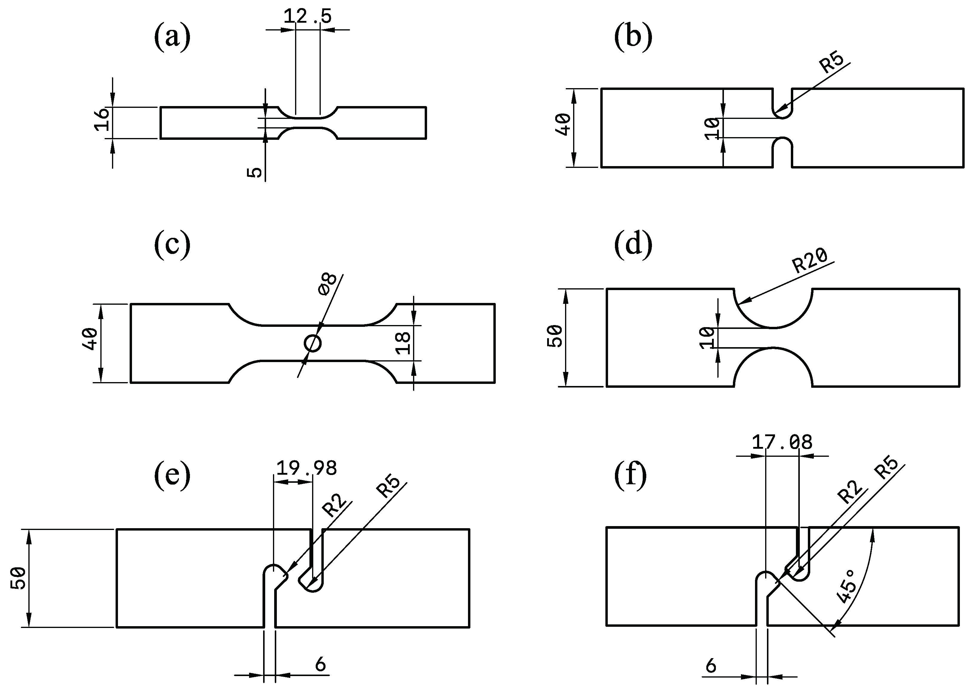
Six types of experiments were conducted to generate the fracture model, representing a wide range of triaxiality and Lode angle parameter values to determine the material properties at quasi-static conditions, as shown in Figure 1 and Table 1.
The tensile test was designed based on a sub-size ASTM-E8M specimen performed to obtain the elastoplastic behavior. The desired stress triaxiality was about 0.33. However, it may shift to a higher value after necking. So, the center hole test was designed to obtain the fracture behavior under 0.33.
R5 and R20 were designed to obtain fracture behaviors under high-stress triaxiality. Moreover, since the necking under these tests was delayed, they could help characterize the plasticity model. Tensile–shear and shear tests were conducted to obtain the ductility under small stress triaxiality states.
Due to the limit of dimensions of the wheel rim, R20 and tensile–shear tests were left out for MAT 1. Additionally, to guarantee the stress state of the thick material MAT 3, the dimensions of its specimens were doubled.
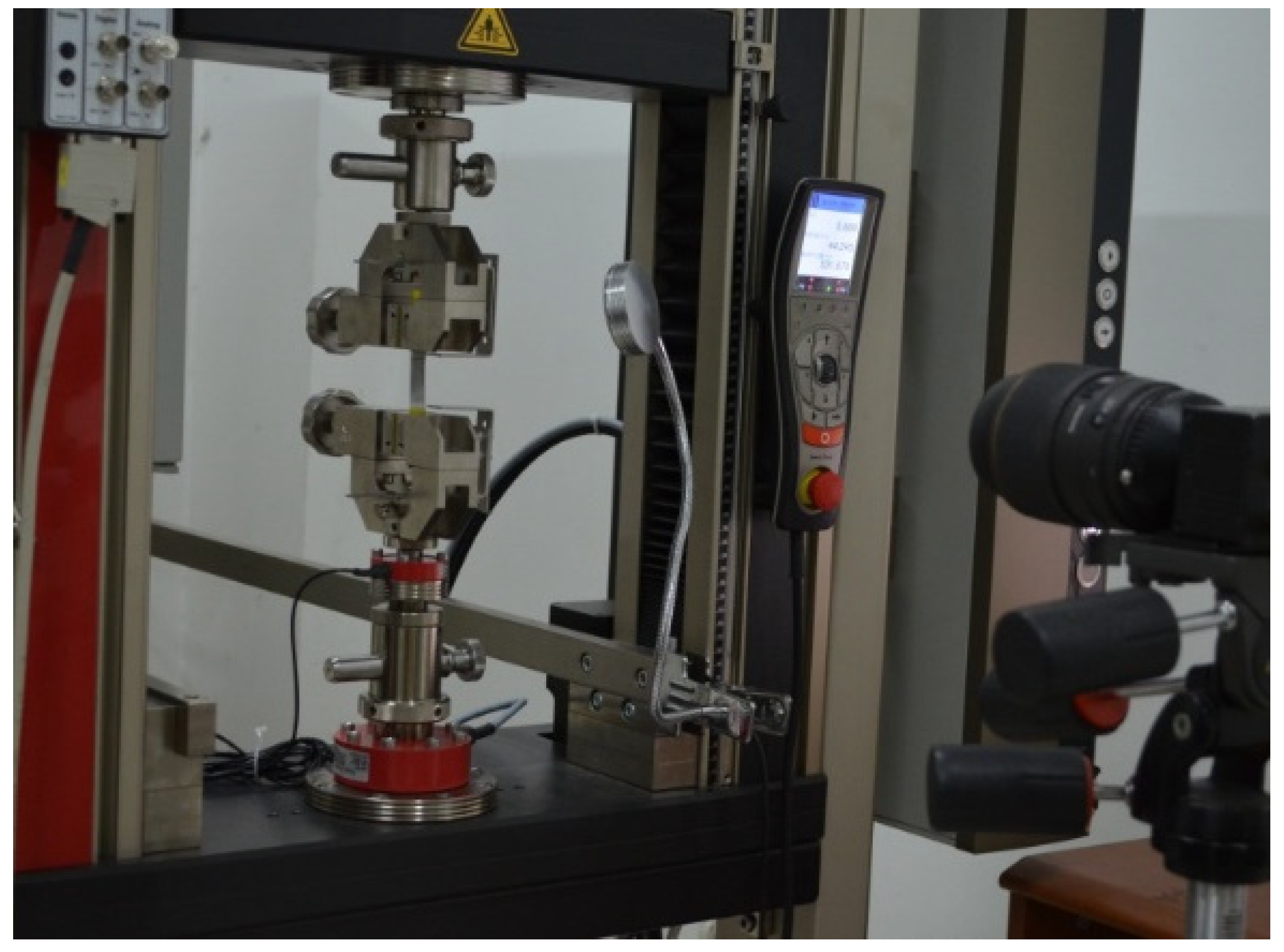
Tests were performed using the universal testing machine, as described in Figure 2. All tests were performed at least three times. The deformation up to fracture was captured using a digital camera, and the displacement and strain data were calculated with the digital image correlation (DIC) software VIC-2D.
2.3. Experimental Results
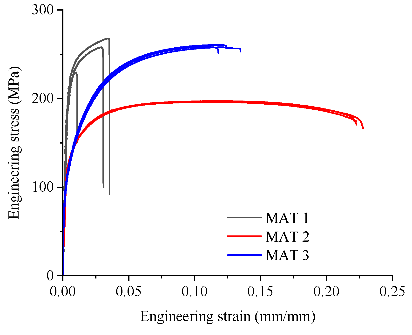
Figure 3 shows the stress vs. strain curves from the quasi-static tension tests of three alloys. The material from the spoke (MAT 1) had the most significant yield and tensile strengths but minor elongation, less than 5%. On the contrary, MAT 2 was the weakest alloy in this study, with the best elongation, which was more than 20%. The alloy’s ductility was outstanding, and the rupture occurred lately after necking. MAT 3, the heat-treatment-free alloy, had a yield strength higher than MAT 2 and a tensile strength lower than MAT 1. The elongation was about 10%, which led to a higher working harden. Moreover, two typical failure behaviors were demonstrated. It could be found that MAT 1 and MAT 3 ruptured rapidly after necking happened, while MAT 2 had an extended post-necking elongation.
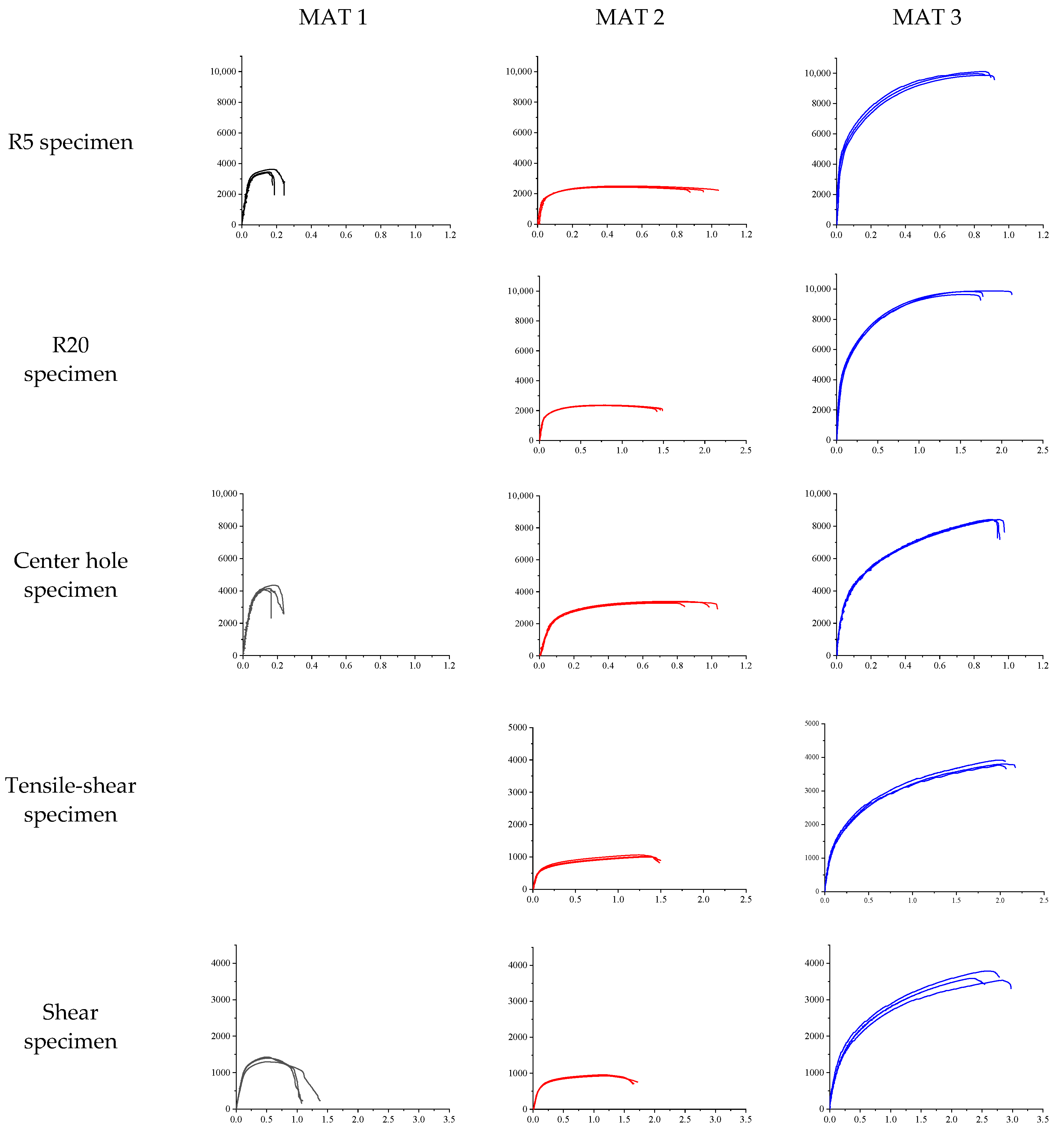
Figure 4 presents the experimental curves of the fracture specimens. The low-elongation MAT 1 gave poor test repeatability, while MAT 2 and MAT 3 showed satisfying repeatability. In R5 and R20 specimen tests, for MAT 1 and MAT 3, the loading dropped rapidly after peak force. However, for MAT 2, the loading dropped smoothly.
3. Characterization of Plasticity and Fracture Behaviors with GISSMO
The commercial FE simulation software LS-DYNA was commonly used to characterize the plasticity and fracture behaviors of the cast alloys. GISSMO was one of the advanced fracture models implemented in LS-DYNA. One crucial aspect is the damage accumulation rule, written as:
where , , , and are the current values of damage, triaxiality, increment of plastic strain, and damage exponent, respectively. The fracture strain is a function of triaxiality. When reached 1.0, a fracture occurred. It enabled GISSMO to give a more accurate depiction of fracture for non-proportional stress paths. Similarly, the instability value was also accumulating:
A softening on the material was enabled after instability, written as:
where is the current value of instability, the instability strain is also a function of triaxiality. is the damage value when and is the fading exponent. Both and can be defined with tabulated curves in GISSMO.
3.1. Shell-Based Model
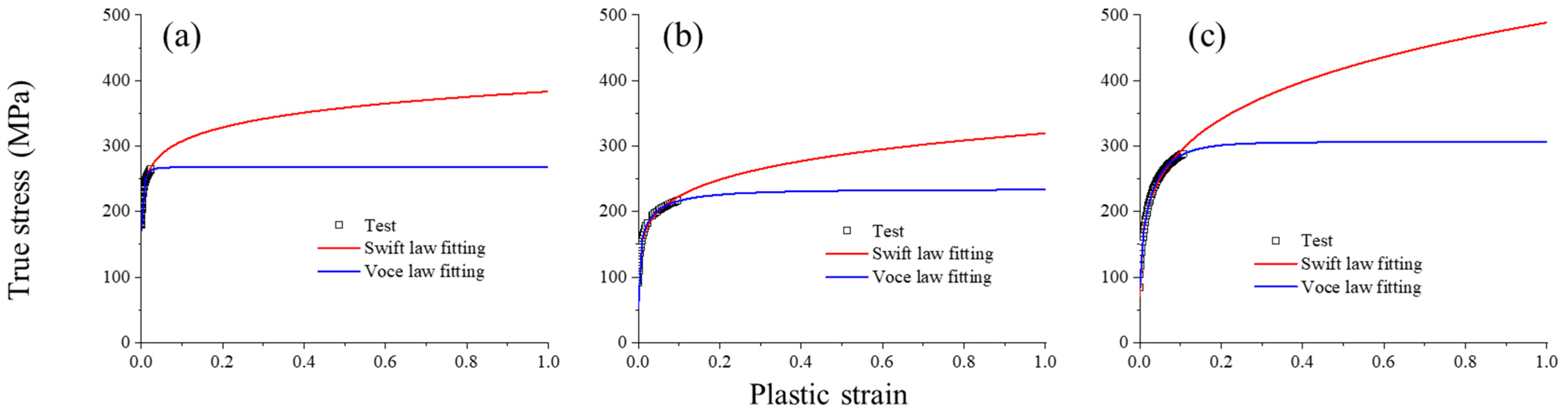
First, shell element-base models were built as benchmarks, then tetrahedral element-based models were established. An isotropic model (MAT_024) was used to describe the elastic-plastic behaviors with an associated flow rule. The commonly used Belytschko–Tsay formula (ELFORM 2) was adopted in the shell element with a mesh size of 0.5 mm. The Voce–Swift isotropic hardening law was used to characterize the plastic hardening behavior before failure for the materials [19]:
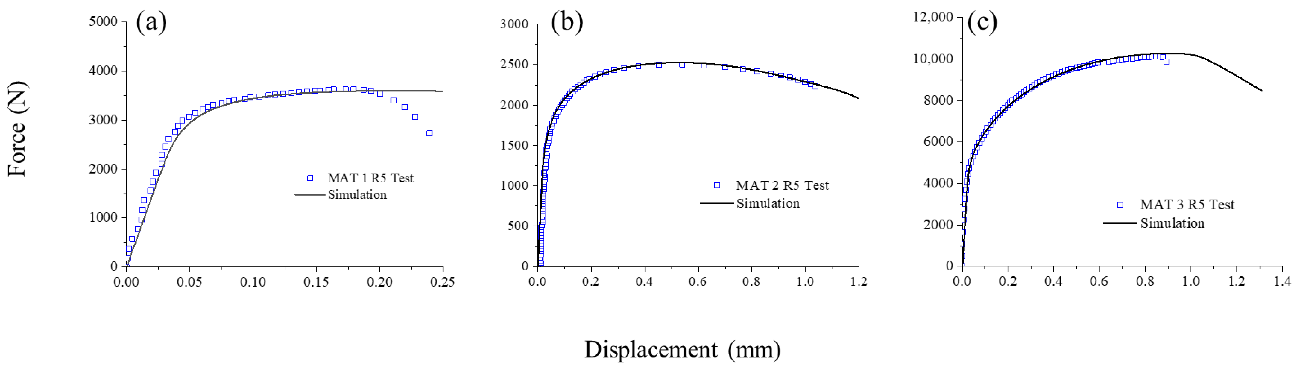
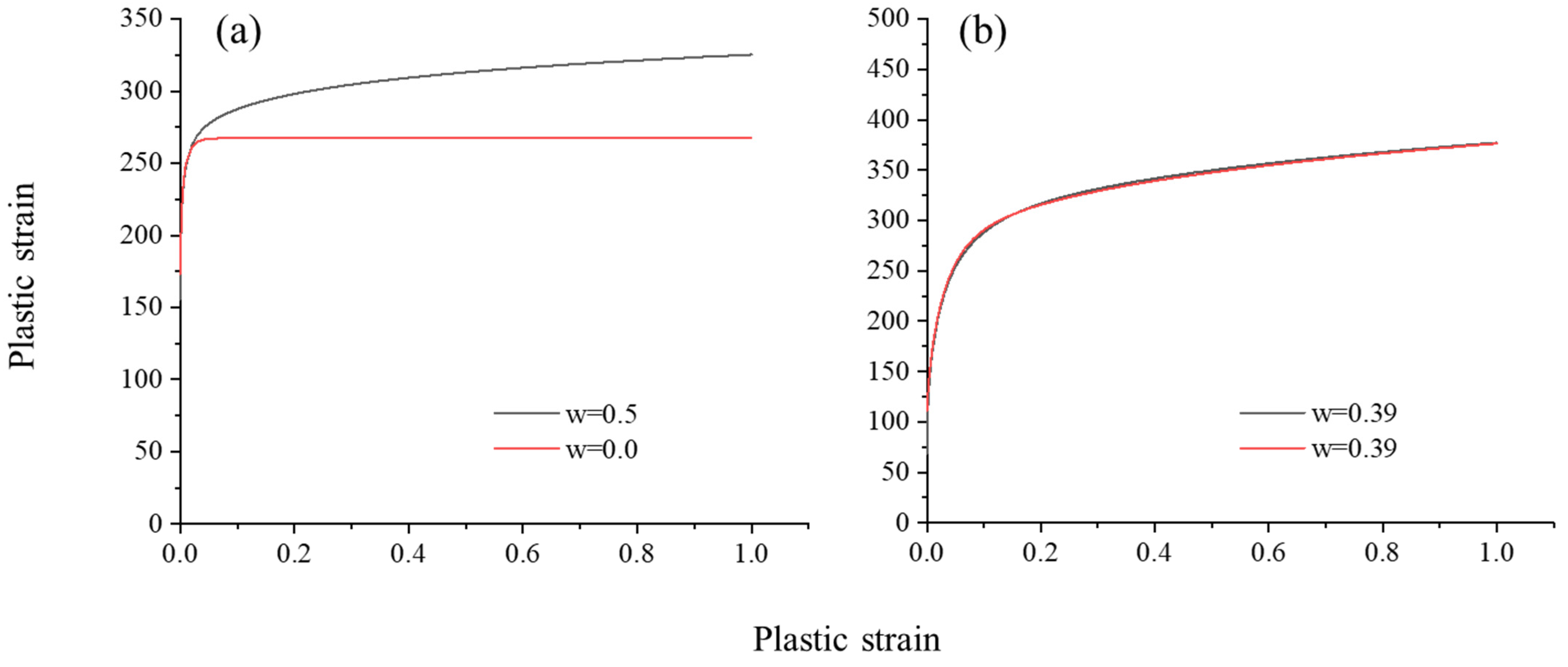
where and denote the effective stress and effective plastic strain, respectively, and , , and represent material constants (). They were obtained from tensile test results before necking, as shown in Figure 5. The similarity of the two fittings was relatively high in the before-necking fragment. Divergence became more significant in the large-strain range, so was used as an adjustable weighting factor in extrapolating the post-necking behavior by comparing R5 notched experimental and numeric results, as shown in Figure 6 and the fitted model parameters were listed in Table 2.
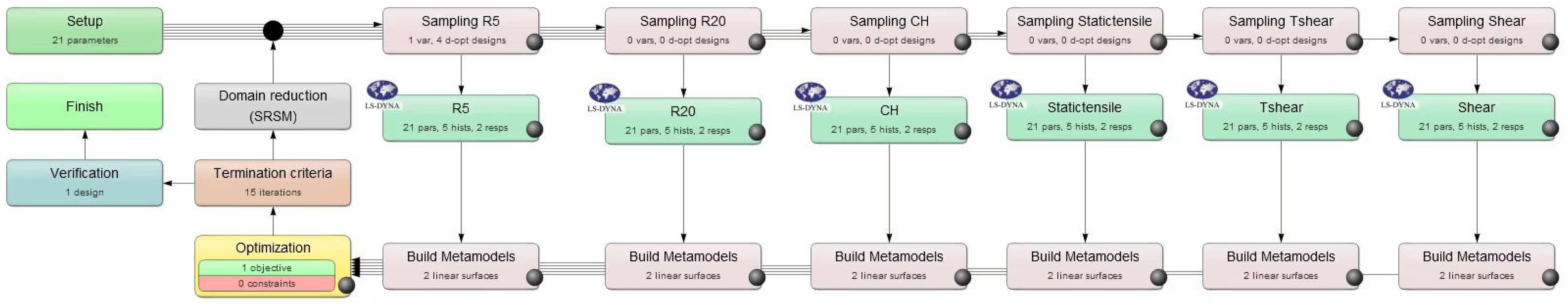
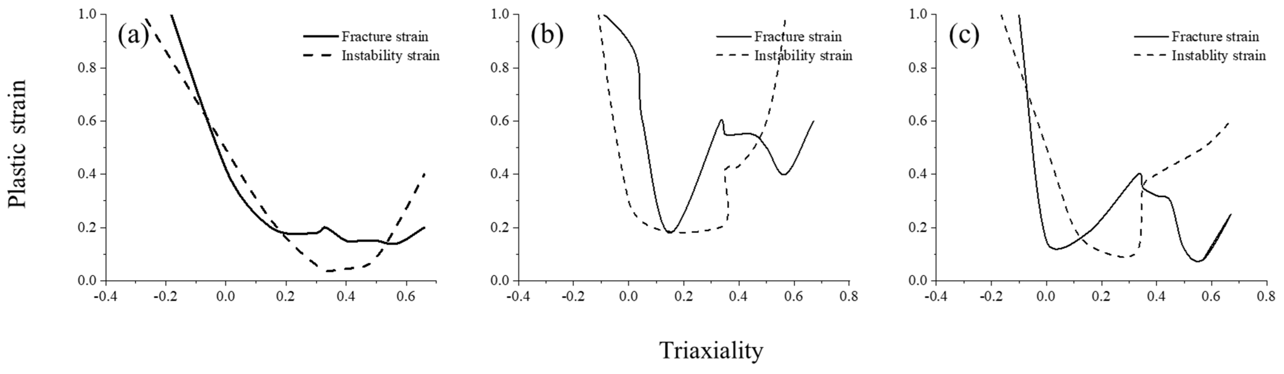
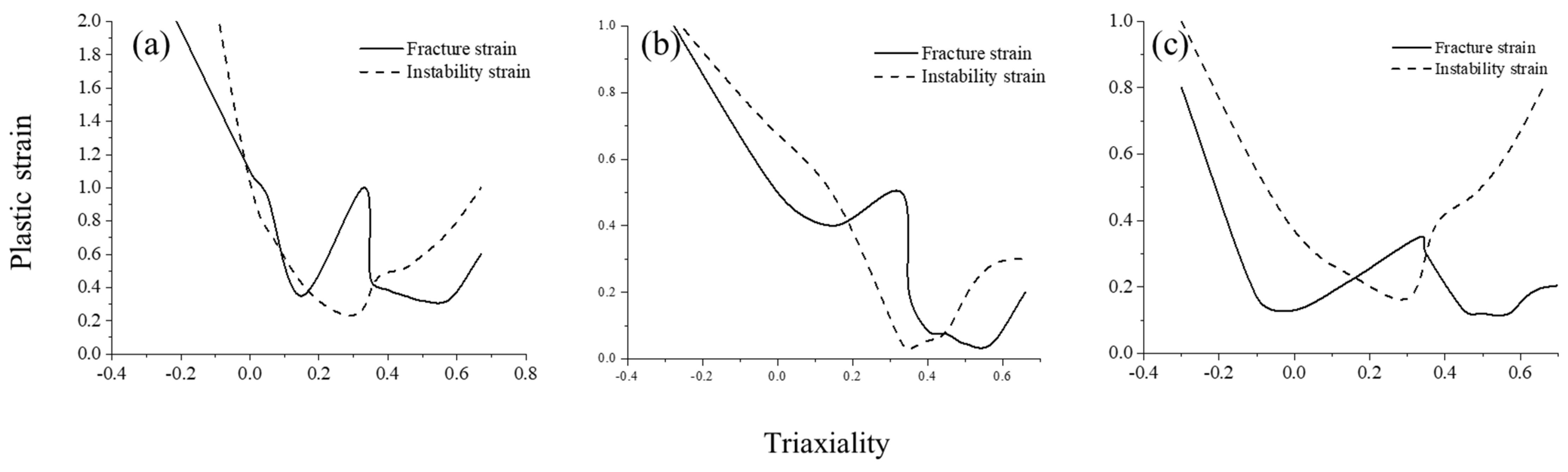
In general, tabulated failure and instability locus led to the flexibility in GISSMO but also the disadvantage that accurate calibrations required practical skills. To conquer this problem, LS-OPT was used in an inverse modeling approach to obtain the magnitude of the equivalent plastic failure strains and instability strains [20,21,22], as shown in Figure 7. First, the parameter space was determined using the designed triaxiality values for both fracture and instability curves. Then, the sequential response surface methodology constructed an approximation between the parameters to the target value. In this study, the target was a summary of the force-displacement curve similarity between experimental and simulation results using dynamic time warping from the six tests. Additionally, several simulations were conducted iteratively in the loop of the differential evolution algorithm to minimize the target value [23]. The magnitudes of the strain values obtained from the optimization procedure were shown in Figure 8.
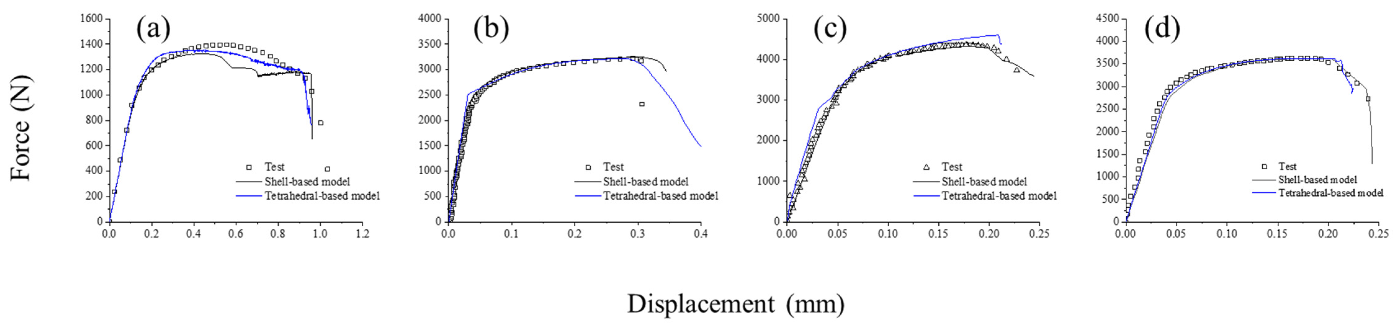
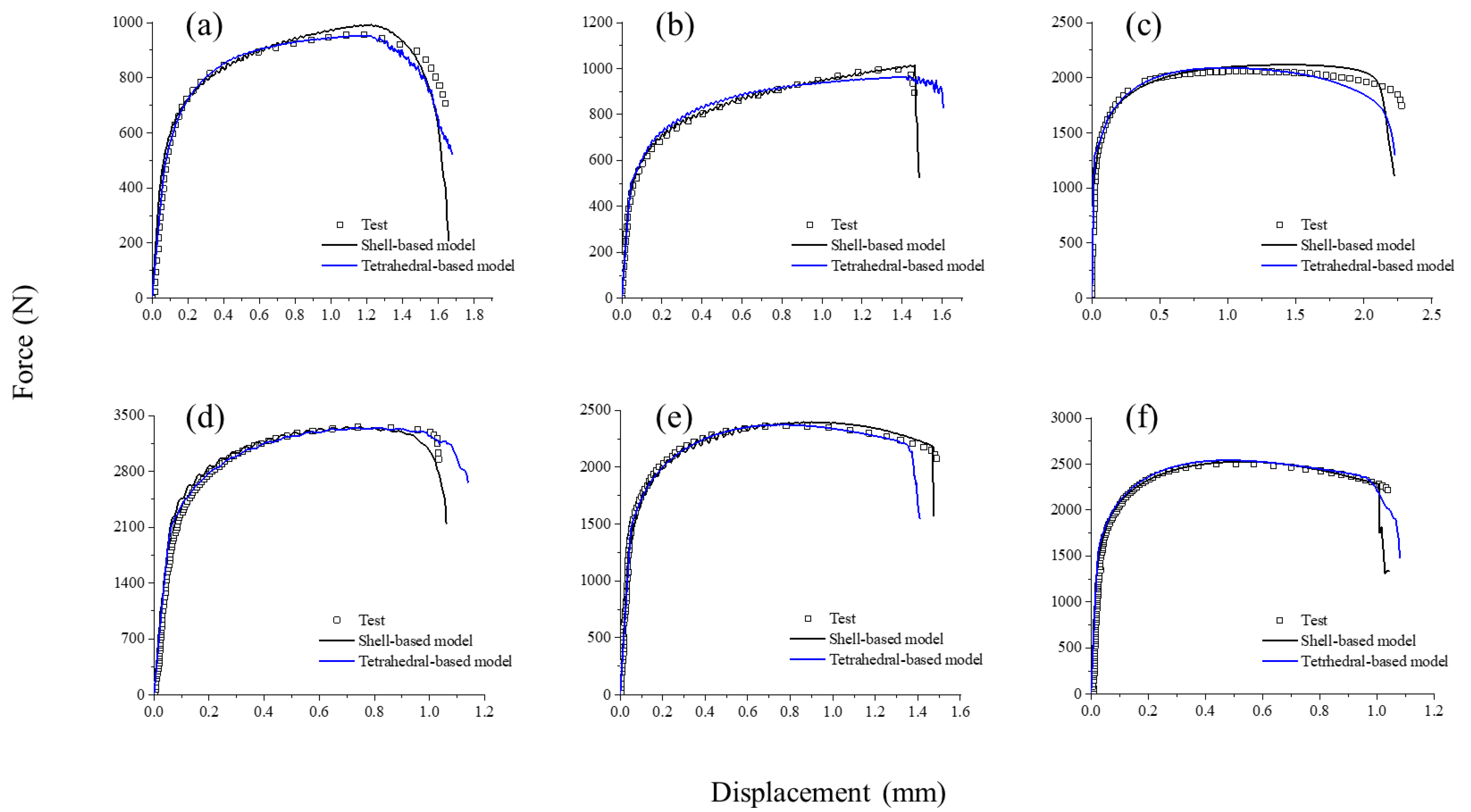
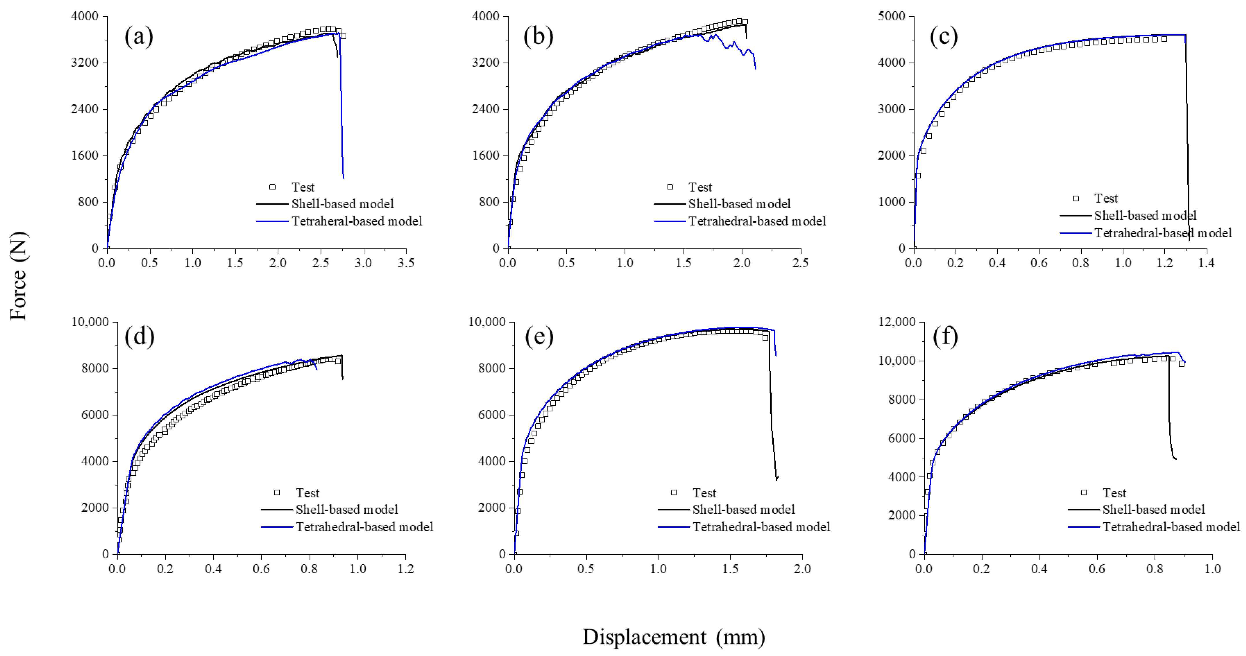
The black lines in Figure 9, Figure 10 and Figure 11 show the comparison of load-displacement curves obtained from numerical and experimental data for the cast aluminum alloys. The shell-based model FE results predicted the elastoplastic and failure behaviors of the alloys with reasonable accuracy.
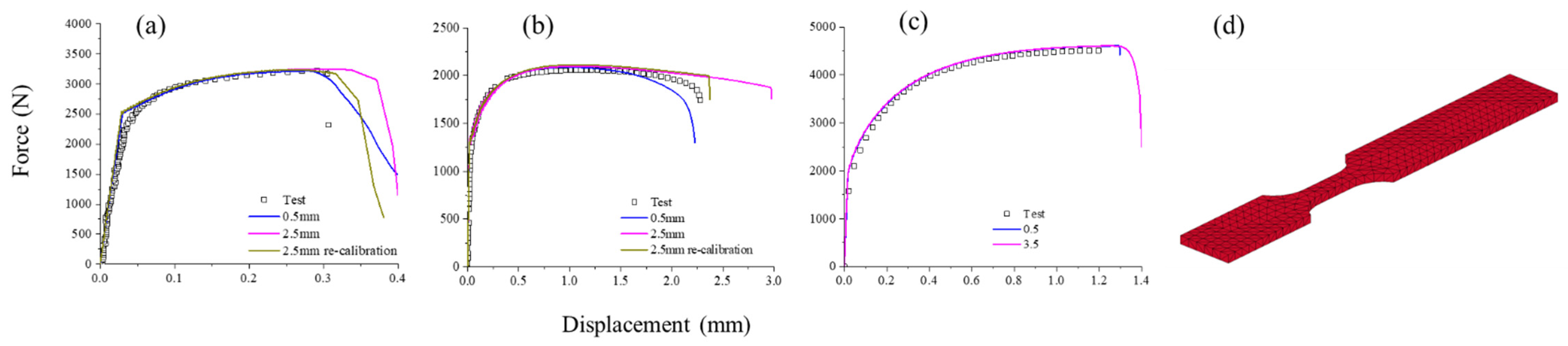
Mesh-size dependence is a well-known issue and plays a significant role in finite element analysis of ductile fracture prediction. After instability, plastic strain tends to depend significantly on the mesh size. GISSMO used tabulated regularization factors to adjust the fracture curve to the corresponding element size [24]. In this case, 2.5 mm and 5 mm were chosen to calibrate the regularization factors. The simulation of a large tensile specimen, three times the original size, was carried out with the calibrated curves, as shown in Figure 12c. It indicated that GISSMO could provide a near-perfect match for these shell-based models with the mesh-dependency regularization factors.
3.2. Tetrahedral-Based Models
First, mesh behavior and convergence rate of four common tetrahedral element formulations in LS-DYNA were investigated for tetrahedral-based models. The element formulations are the one-point constant stress element (ELFORM 10), one-point constant stress with nodal pressure averaging element (ELFOREM 13), S/R quadratic with nodal rotation element (ELFORM 4), and point 10-noded element (ELFORM 16).
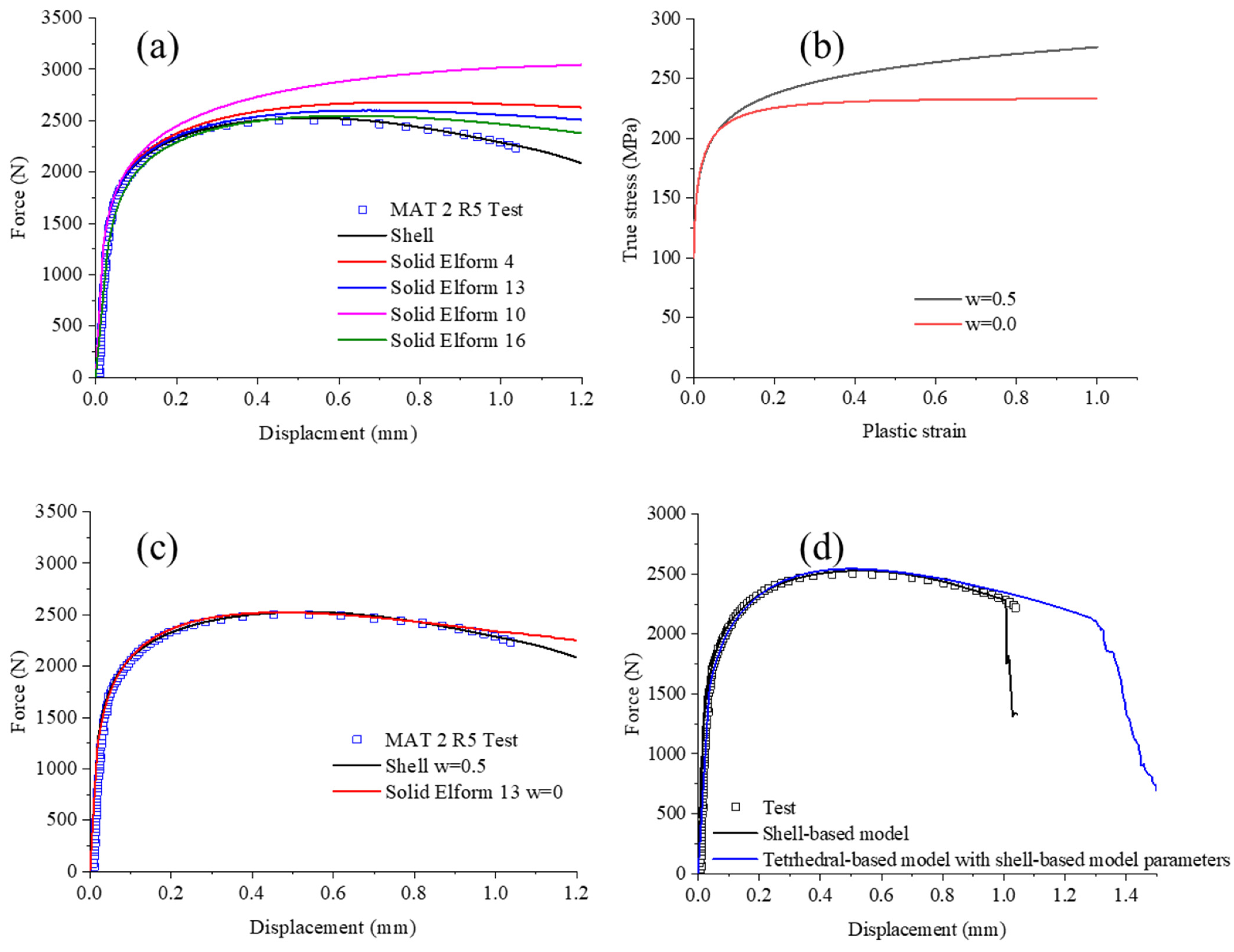
For instance, the force-displacement curves of the R5 notched specimen of MAT 2 obtained from simulations of the four formulas were compared with those from the experiments and shell-based simulations. The initial hardening curve was as same as the shell-based model. All the formulas overestimated the strain-hardening. Moreover, the time-consuming comparison was listed in Table 3. As Figure 13a, ELFORM 16 gave the most likely prediction but was also the most time-consuming. ELFORM 13 indicated an acceptable accuracy at minor strain conditions and was reasonably time-consuming. However, it deviated from the experimental data by approximately 10% at large strain. ELFORM 4 element model started shifting from a relatively minor strain, and the differences were enlarged along with strain. ELFORM 10, on the other hand, gave a much higher response at the very beginning. The results indicated that the ELFORM 16 and 13 elements could be the candidates for accurate reproduction of experiments, and ELFORM 13 was the more effective one. Recalibrating the weighting factor could solve the overestimating problem in the ELFORM 13 model. As seen in Figure 13b,c, with , the improved simulation result using ELFORM 13 matched the experimental result in an acceptable agreement in all strain ranges. ELFORM 13 could be the best choice for tetrahedral models in crashworthiness simulations.
A similar pattern was also found in MAT 1. The weighting factor reproduced the experimental result with reasonable accuracy. However, in MAT 3, the original hardening curve from the shell-based model with was also suitable for the tetrahedral-based model, as seen in Figure 14. It might be attributed to the higher working harden and the rapid failure after peak force. So, the extrapolating factor did not influence the mechanical behavior of the models significantly.
Second, the GISSMO model parameters from the shell-based model were also applied in the tetrahedral models for MAT 2, seeing the blue line in Figure 13d. It demonstrated a noticeable fracture delay and led to an overestimation of structural integrity. Thus, the failure locus in the tetrahedral-based model should be lower even if the weighting factor was already decreased. It indicated that the GISSMO parameters should be recalibrated for different element formulas, even for MAT 3, which used the same hardening curve in the shell-based model. The failure and instability loci used in tetrahedral-based models were shown in Figure 15, and the simulation results were demonstrated with blue lines in Figure 9, Figure 10 and Figure 11. The models presented good agreement between simulations and experiments.
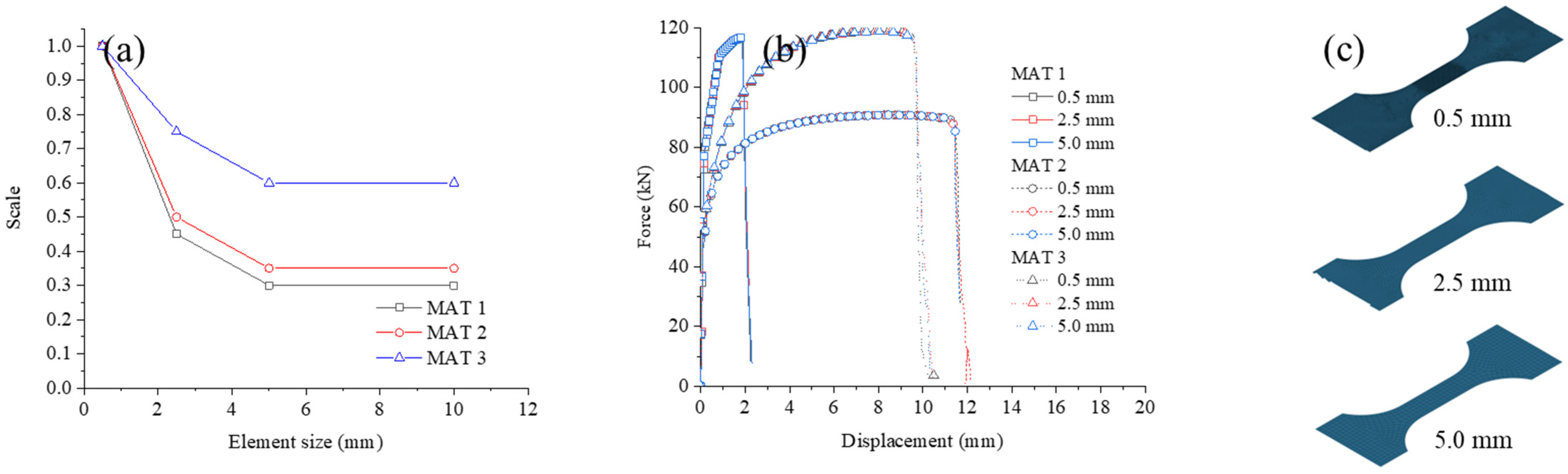
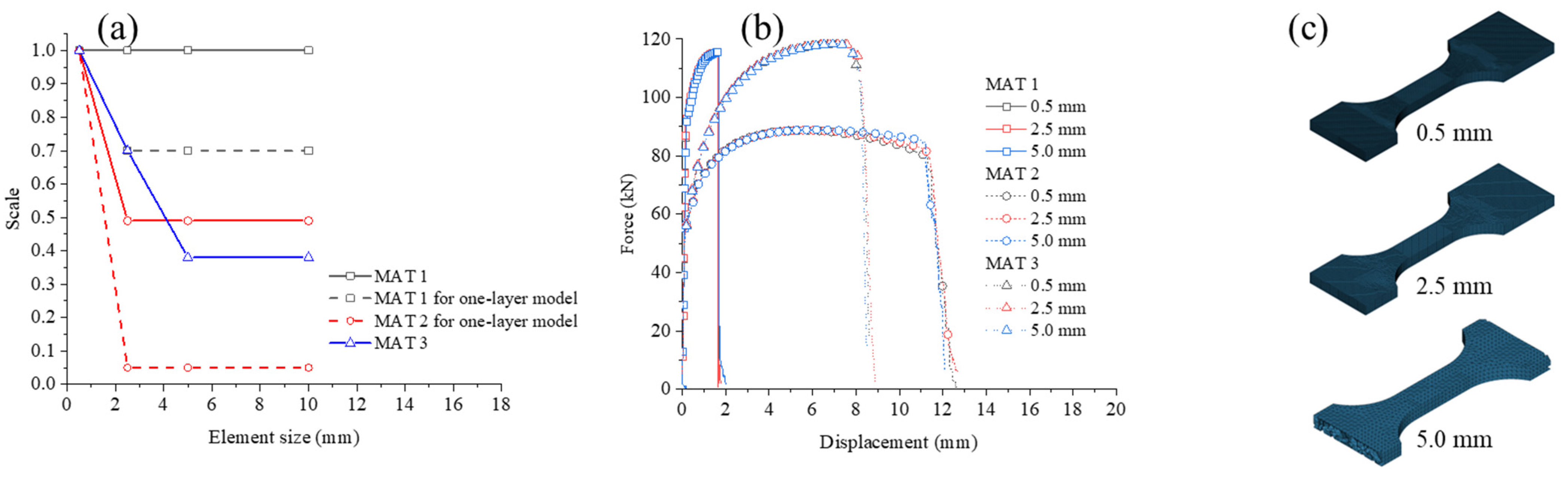
Additionally, 2.5 mm and 5 mm meshes were also investigated concerning the sensitivity to mesh dependence. The specimen’s geometry was the same as the shell-based model; at least three layers of elements were divided in the specimen models. The solid lines in Figure 16a show the regularization factors of the three different alloys, which were very different from the ones used in shell-based models. Simulation results in these mesh sizes were displayed in Figure 16b. It became evident that well-calibrated regularization factors in GISSMO could provide a satisfying match in most cases. It is worth noting that the mesh-size sensitivity of MAT 1 was very low. It indicated that the mesh dependency could be ignored in well-defined tetrahedral-based models with low-ductility materials.
Another important point when working with tetrahedral elements was the possibility of using a one-layer element model for thin-walled complex-shaped structures. The size dependence for these models was also investigated using the original tensile specimens. As shown in Figure 17, the one-layer model showed a pronounced delay in failure for MAT 1 and MAT 2, while an acceptable match for MAT 3. In some cases, the regularization factors were unsuitable for the one-layer element model. It could also be attributed to the higher working harden and the rapid failure after necking. The dashed lines in Figure 16a show the recalibrated factors used in one-layer models, and better matching simulation results were obtained.
4. Discussion
To better understand their differences, a discussion and comparison of the GISSMO failure models for both shell- and tetrahedral-based models.
The type of element formulas used in the tetrahedral-based model could significantly influence the simulation results. Four different types were evaluated and compared, which indicated that the model was susceptible to the element type. Both ELFORM 16 and ELFORM 13 could reproduce the experiments in good agreement, but with less time consumption, ELFORM 13 could be the best candidate for the tetrahedral-based model for crashworthiness simulations.
Despite contrasting differences, with recalibrating the weighting factor in extrapolating harden curves, instability, and failure strain loci, satisfying results could be achieved with both shell-based and tetrahedral-based models. Shell-based parameters used in the tetrahedral-based model usually led to overestimating the force and delay in fracture. However, the heat treatment-free alloy (MAT 3) presented a similar hardening behavior in both shell-based and tetrahedral-based models.
Moreover, GISSMO could also provide a satisfying match for all element sizes and formulas with good calibration of the regularization factors. It is difficult to affirm if the tetrahedral-based model was more or less sensitive to mesh size.
Nevertheless, the alloy from the spoke (MAT 1) results indicated that the poor elongation alloys could be insensitive to the mesh size in tetrahedral-based models.
In addition, the one-layer tetrahedral-based model, though not recommended, showed more sensitivity to the mesh size. Further recalibration for the regularization factors was required for these models.
5. Conclusions
This paper studied the material fracture behaviors of three commercial cast aluminum alloys in the automotive industry with very different mechanical behaviors using GISSMO. Six different types of specimens were designed and tested with a large variety of stress states at failure. Some main conclusions can be drawn:
- With the well-calibrated parameters, GISSMO could reproduce the test results with good agreement for the multiple stress states.
- Optimization with LS-OPT was a feasible way to calibrate the parameters for GISSMO and avoid the requirement of practical skills.
- The part structures tests and simulations should be conducted in future work to evaluate whether the tetrahedral-based model with GISSMO is suitable.
Author Contributions
Conceptualization, Y.G. and L.G.; methodology, L.G. and R.X.; validation, L.D. and H.S.; resources, H.S.; data curation, Y.G. and L.G.; writing—original draft preparation, Y.G. and L.G.; writing—review and editing, R.X.; visualization, Y.G.; project administration, L.D.; funding acquisition, R.X. All authors have read and agreed to the published version of the manuscript.
Funding
This research was funded by the National Natural Science Foundation of China, grant number 51905512.
Institutional Review Board Statement
Not applicable.
Informed Consent Statement
Not applicable.
Data Availability Statement
Not applicable.
Conflicts of Interest
The authors declare no conflict of interest.
References
- Corona, E.; Reedlunn, B. A Review of Macroscopic Ductile Failure Criteria; Sandia National Laboratories: Livermore, CA, USA, 2013. [Google Scholar]
- McClintock, F.A. A Criterion for Ductile Fracture by the Growth of Holes. J. Appl. Mech. 1968, 35, 363–371. [Google Scholar] [CrossRef]
- Rice, J.R.; Tracey, D.M. On the ductile enlargement of voids in triaxial stress fields. J. Mech. Phys. Solids 1969, 17, 201–217. [Google Scholar] [CrossRef] [Green Version]
- Gurson, A.L. Continuum Theory of Ductile Rupture by Void Nucleation and Growth: Part I—Yield Criteria and Flow Rules for Porous Ductile Media. J. Eng. Mater. Technol. 1977, 99, 2–15. [Google Scholar] [CrossRef]
- Bao, Y.; Wierzbicki, T. On fracture locus in the equivalent strain and stress triaxiality space. Int. J. Mech. Sci. 2004, 46, 81–98. [Google Scholar] [CrossRef]
- Mae, H.; Teng, X.; Bai, Y.; Wierzbicki, T. Calibration of ductile fracture properties of a cast aluminum alloy. Mater. Sci. Eng. A 2007, 459, 156–166. [Google Scholar] [CrossRef]
- Bai, Y.; Wierzbicki, T. A new model of metal plasticity and fracture with pressure and Lode dependence. Int. J. Plast. 2008, 24, 1071–1096. [Google Scholar] [CrossRef]
- Luo, M.; Dunand, M.; Mohr, D. Experiments and modeling of anisotropic aluminum extrusions under multi-axial loading—Part II: Ductile fracture. Int. J. Plast. 2012, 32–33, 36–58. [Google Scholar] [CrossRef]
- Lee, J.; Kim, S.-J.; Park, H.; Bong, H.J.; Kim, D. Metal plasticity and ductile fracture modeling for cast aluminum alloy parts. J. Mater. Process. Technol. 2018, 255, 584–595. [Google Scholar] [CrossRef]
- Pack, K.; Mohr, D. Combined necking & fracture model to predict ductile failure with shell finite elements. Eng. Fract. Mech. 2017, 182, 32–51. [Google Scholar]
- Pack, K.; Roth, C.C. The second Sandia Fracture Challenge: Blind prediction of dynamic shear localization and full fracture characterization. Int. J. Fract. 2016, 198, 197–220. [Google Scholar] [CrossRef] [Green Version]
- Mohr, D.; Marcadet, S.J. Micromechanically-motivated phenomenological Hosford–Coulomb model for predicting ductile fracture initiation at low stress triaxialities. Int. J. Solids Struct. 2015, 67–68, 40–55. [Google Scholar] [CrossRef]
- Lee, J.-Y.; Steglich, D.; Lee, M.-G. Fracture prediction based on a two-surface plasticity law for the anisotropic magnesium alloys AZ31 and ZE10. Int. J. Plast. 2018, 105, 1–23. [Google Scholar] [CrossRef]
- Walters, C.L. Framework for adjusting for both stress triaxiality and mesh size effect for failure of metals in shell structures. Int. J. Crashworthiness 2014, 19, 1–12. [Google Scholar] [CrossRef]
- Hoque, S.E.; Scheiblhofer, S.; Ucsnik, S. A comparative study of the hexahedral elements in LS-DYNA for crashworthiness simulation. In Proceedings of the 12th European LS-DYNA Conference, Koblenz, Germany, 14–16 May 2019. [Google Scholar]
- Kim, D.-Y.; Han, Y.; Shin, S.; Yook, H. Numerical Fracture Analysis Considering Forming Effect and Element Size Regularization for Automotive Seat Structures. SAE Int. J. Engines 2017, 10, 287–295. [Google Scholar] [CrossRef]
- Eriksson, V. Numerical Simulation of Ductile Cast Iron Fracture: A parameterization of the material model *MAT_224 in the FE-code LS-DYNA. Master’s Thesis, Karlstad University, Karlstad, Sweden, 2013. [Google Scholar]
- Leost, Y.; Sonntag, A.; Haase, T. Modeling of a Cast Aluminum Wheel for Crash Application. In Proceedings of the 11th European LS-DYNA Conference, Salzburg, Austria, 9–11 May 2017. [Google Scholar]
- Sung, J.H.; Kim, J.H.; Wagoner, R.H. A plastic constitutive equation incorporating strain, strain-rate, and temperature. Int. J. Plast. 2010, 26, 1746–1771. [Google Scholar] [CrossRef]
- Johnsen, J.; Holmen, J.K.; Gruben, G.; Morin, D.; Langseth, M. Calibration and Application of GISSMO and* MAT_258 for Simulations Using Large Shell Elements. In Proceedings of the 16th International LS-DYNA User Conference, Online, 10–11 June 2020. [Google Scholar]
- Chen, X.; Chen, G.; Huang, L. Validation of GISSMO model for fracture prediction of a third-generation advanced high-strength steel. SAE Int. J. Mater. Manuf. 2018, 11, 293–302. [Google Scholar] [CrossRef]
- Gu, B.; Lim, J.; Hong, S. Determination and Verification of GISSMO Fracture Properties of Bolts Used in Radioactive Waste Transport Containers. Materials 2022, 15, 1893. [Google Scholar] [CrossRef] [PubMed]
- Ge, Y.-l.; Li, X.-X.; Lang, L.-H.; Ruan, S.-W. Optimized design of tube hydroforming loading path using multi-objective differential evolution. Int. J. Adv. Manuf. Technol. 2017, 88, 837–846. [Google Scholar] [CrossRef]
- Andrade, F.; Feucht, M.; Haufe, A. On the Prediction of Material Failure in LS-DYNA®: A Comparison between GISSMO and DIEM. In Proceedings of the 13th International LS-DYNA Users Conference, Detroit, MI, USA, 8 June 2014. [Google Scholar]
Figure 1.
Specimen configuration for the tests (unit: mm): (a) Tensile, (b) R5 notched, (c) Center hole, (d) R20 notched, (e) Shear, and (f) Tensile-shear.
Figure 1.
Specimen configuration for the tests (unit: mm): (a) Tensile, (b) R5 notched, (c) Center hole, (d) R20 notched, (e) Shear, and (f) Tensile-shear.

Figure 2.
Experimental methodology. Zwick Z020 universal test machine and DIC system.

Figure 3.
Engineering stress vs. strain curves of the three alloys.

Figure 4.
Experimental results (horizontal axis unit: mm; longitudinal axis: N).

Figure 5.
True stress–plastic strain curves and hardening-law fittings before necking: (a) MAT 1, (b) MAT 2, and (c) MAT 3.
Figure 5.
True stress–plastic strain curves and hardening-law fittings before necking: (a) MAT 1, (b) MAT 2, and (c) MAT 3.

Figure 6.
Isotropic hardening-law fittings before necking using R5 test results: (a) MAT 1, (b) MAT 2, and (c) MAT 3.
Figure 6.
Isotropic hardening-law fittings before necking using R5 test results: (a) MAT 1, (b) MAT 2, and (c) MAT 3.

Figure 7.
LS-OPT scheme for GISSMO calibration.

Figure 8.
Optimized failure and instability loci using GISSMO for shell-based models: (a) MAT 1, (b) MAT 2, and (c) MAT 3.
Figure 8.
Optimized failure and instability loci using GISSMO for shell-based models: (a) MAT 1, (b) MAT 2, and (c) MAT 3.

Figure 9.
Shell-based model simulation vs. experiments for MAT 1 using GISSMO: (a) shear specimen, (b) tensile specimen, (c) center hole specimen, and (d) R5 specimen.
Figure 9.
Shell-based model simulation vs. experiments for MAT 1 using GISSMO: (a) shear specimen, (b) tensile specimen, (c) center hole specimen, and (d) R5 specimen.

Figure 10.
Shell-based model simulation vs. experiments for MAT 1 using GISSMO: (a) shear specimen, (b) tensile–shear specimen, (c) tensile specimen, (d) center hole specimen, (e) R20 notched specimen, and (f) R5 notched specimen.
Figure 10.
Shell-based model simulation vs. experiments for MAT 1 using GISSMO: (a) shear specimen, (b) tensile–shear specimen, (c) tensile specimen, (d) center hole specimen, (e) R20 notched specimen, and (f) R5 notched specimen.

Figure 11.
Shell-based model simulation vs. experiments for MAT 3 using GISSMO: (a) shear specimen, (b) tensile–shear specimen, (c) tensile specimen, (d) center hole specimen, (e) R20 notched specimen, and (f) R5 notched specimen.
Figure 11.
Shell-based model simulation vs. experiments for MAT 3 using GISSMO: (a) shear specimen, (b) tensile–shear specimen, (c) tensile specimen, (d) center hole specimen, (e) R20 notched specimen, and (f) R5 notched specimen.

Figure 12.
Mesh-dependency regularization factors for shell-based models: (a) Mesh dependency regularization factors, (b) Simulation results and (c) Tensile specimen models with different mesh sizes.
Figure 12.
Mesh-dependency regularization factors for shell-based models: (a) Mesh dependency regularization factors, (b) Simulation results and (c) Tensile specimen models with different mesh sizes.

Figure 13.
Tetrahedral elements comparisons for MAT 2: (a) element formulas, (b) extrapolating curves, (c) R5 model with a recalibrated weighting factor, and (d) R5 model with the shell-based GISSMO.
Figure 13.
Tetrahedral elements comparisons for MAT 2: (a) element formulas, (b) extrapolating curves, (c) R5 model with a recalibrated weighting factor, and (d) R5 model with the shell-based GISSMO.

Figure 14.
Extrapolating curves of tetrahedral-based models for (a) MAT 1 and (b) MAT 3.

Figure 15.
Optimized failure and instability loci using GISSMO for tetrahedral-based models: (a) MAT 1, (b) MAT 2, and (c) MAT 3.
Figure 15.
Optimized failure and instability loci using GISSMO for tetrahedral-based models: (a) MAT 1, (b) MAT 2, and (c) MAT 3.

Figure 16.
Mesh-dependency regularization factors for tetrahedral-based models: (a) Mesh dependency regularization factors, (b) Simulation results, and (c) Tensile specimen models with different mesh sizes.
Figure 16.
Mesh-dependency regularization factors for tetrahedral-based models: (a) Mesh dependency regularization factors, (b) Simulation results, and (c) Tensile specimen models with different mesh sizes.

Figure 17.
Recalibrated results for one-layer models: (a) MAT 1, (b) MAT 2, (c) MAT 3 and (d) One-layer tensile specimen models.
Figure 17.
Recalibrated results for one-layer models: (a) MAT 1, (b) MAT 2, (c) MAT 3 and (d) One-layer tensile specimen models.


Table 1.
Experimental conditions for designed specimens.
| Test # | Specimen | Desired | Desired |
|---|---|---|---|
| a | Tensile | 0.33 | 1 |
| b | R5 notched | 0.5 | 0.35 |
| c | Center hole | 0.38 | 0.85 |
| d | R20 notched | 0.40 | 0.80 |
| e | Tensile–shear | 0.10 | 0.25 |
| f | Shear | 0.0 | 0.0 |
Table 2.
Material parameters fitted for three alloys.
| # | ||||||||
|---|---|---|---|---|---|---|---|---|
| MAT 1 | 383.143 | 0.09532 | 2.20 × 10⁻⁵ | 267.504 | 94.2477 | 40.0521 | 0.68908 | 0.5 |
| MAT 2 | 319.5 | 0.15532 | 1.2 × 10⁻⁵ | 267.504 | 186.023 | 6.12133 | 0.41562 | 0.5 |
| MAT 3 | 488.515 | 0.22313 | 1.9 × 10⁻⁵ | 306.092 | 221.370 | 11.5027 | 0.68509 | 0.39 |
Table 3.
CPU times for tetrahedral element models (R13.0 MPP with Intel® Xeon® E5-2687W).
| ELFORM 4 | ELFORM 10 | ELFORM 13 | ELFORM 16 |
|---|---|---|---|
| 149 s | 43 s | 49 s | 205 s |
Publisher’s Note: MDPI stays neutral with regard to jurisdictional claims in published maps and institutional affiliations. |
© 2022 by the authors. Licensee MDPI, Basel, Switzerland. This article is an open access article distributed under the terms and conditions of the Creative Commons Attribution (CC BY) license (https://creativecommons.org/licenses/by/4.0/).
Share and Cite
MDPI and ACS Style
Ge, Y.; Dong, L.; Song, H.; Gao, L.; Xiao, R. On the Prediction of Material Fracture for Thin-Walled Cast Alloys Using GISSMO. Metals 2022, 12, 1850. https://doi.org/10.3390/met12111850
AMA Style
Ge Y, Dong L, Song H, Gao L, Xiao R. On the Prediction of Material Fracture for Thin-Walled Cast Alloys Using GISSMO. Metals. 2022; 12(11):1850. https://doi.org/10.3390/met12111850
Chicago/Turabian StyleGe, Yulong, Liping Dong, Huibin Song, Lechen Gao, and Rui Xiao. 2022. "On the Prediction of Material Fracture for Thin-Walled Cast Alloys Using GISSMO" Metals 12, no. 11: 1850. https://doi.org/10.3390/met12111850
Note that from the first issue of 2016, this journal uses article numbers instead of page numbers. See further details here.