Article

Effect of Brazing Filler Metals and Welding Parameters on Laser Welding-Brazing Joints of WC-Co to S1045

1
School of Materials Science and Engineering, Shanghai University of Engineering Science, Shanghai 201620, China
2
Shanghai Collaborative Innovation Center of Laser Advanced Manufacturing Technology, Shanghai 201620, China
*
Author to whom correspondence should be addressed.
Metals 2022, 12(11), 1780; https://doi.org/10.3390/met12111780
Submission received: 20 September 2022 / Revised: 16 October 2022 / Accepted: 19 October 2022 / Published: 22 October 2022

Abstract

:
Laser welding-brazing was used to join cemented carbide WC-Co and steel dissimilar materials. In this study, high-speed welding was adopted. The effect of welding parameters and brazing filler metals on the macrostructure, elemental diffusion, micro hardness and thermomechanical behavior was analyzed using optical metallography, scanning electron microscopy, electron probe micro-analysis, hardness test, and finite element method (FEM) based on thermo-elastic-plastic analysis. The experimental results show that increasing laser power is helpful to the increase of maximum welding speed. However, FEM also shows that increased welding speed leads to residual stress concentration, especial in the vicinity of jig. It is still a challenge to optimize laser power welding speed for a given brazing filler metal. The results show: when using pure copper, silver and nickel (thickness is less than 0.5 mm) as brazing filler metal, the combination, laser power of 1.2 kW and welding speed at 0.1 m/s, leads to complete penetration with good weld formation. However, when using Cu/Invar/Ni as brazing filler metal, laser power should increase to 1.7 kW if we still using a higher welding speed (0.1 m/s). Although a trial of high speed welding in laser welding-brazing exhibits feasibility, as-welded joints still have much more brittle risks due to the higher residual stresses.

1. Introduction

Cemented carbides are widely used for high-speed cutting, printed circuit board drilling, rolling, and mining (die, rings, rolls, blades, slitters, totoras, and stators) as cemented carbide or cemented carbide–steel composites [1,2,3,4]. Composites such as valves, tools, and seals are frequently fabricated by parts made of as-welded joints between cemented carbide and steel bodies [5,6].
Parts based on as-welded joints of cemented carbide and steel have different demand backgrounds, and there are about dozens of methods to fabricate cemented carbide and steel welds [7,8,9,10]. Vacuum sintering and brazing are common techniques. Vacuum sintering [11,12] is generally used for parts with large stress and regular shape in service. Brazing can be used for the fabrication of parts with complex shapes, mainly used for sealing with low service stress [13,14], or backing welding for coating tools fabrication before mechanical joining [15].
Investigation on weldability of cemented carbide and steels has been carried out since the application of cemented carbide and tool and method of making the same [16,17]. Initial studies focused on the low wettability due to large mechanical properties between cemented carbide and steels, residual stress after weld thermal cycle, and metal dissolution in the bonding phases [18,19,20,21,22,23], which was the main mechanism causing the poor wettability [24].
Further studies suggest that the joint embrittlement is caused by the formation of compound carbides such as M6C (Co3W3C), M12C (Co6W6C) on the WC-Co side and martensite formed in the heat-affected zone (HAZ) on the steel side [25,26,27]. The tungsten carbide of the fusion boundary region on the WC-Co side distributes gradually across the as-welded joint, which is helpful to the formation of transition layer between cemented carbide and steel [28]. The loss of carbon during the dissolution of tungsten carbide further increases the risk of joint embrittlement [29,30]. In addition, bond phase (cobalt) weakening [31] and interface weakening [32,33] are also important factors causing structural failure.
Residual stresses in the as-welded joints can affect both the static strength and the fatigue endurance of welded joints [34]. X-ray diffraction [35] can be used to measure residual stress using the distance between crystallographic planes. Residual stress measurement with neutron diffraction [36] can provides a 3-D map of the full residual stress tensor with a good resolution. This is a nondestructive testing method and enables the quantitative detection of residual stresses. Residual stresses can also be measured by a combination of acoustoelastic and optical interferometry [37]. Besides the above experimental methods, numerical simulation can also be used to assess residual stresses in the as-welded joints [38].
Combining the advantages of laser welding and brazing [13,39], laser welding-brazing can accurately control the weld position without heating the whole cemented carbide and reduce the damage to the cemented carbide.
In this research, we aim to investigate the effects of laser welding-brazing parameters and brazing filler materials on the macroscopic morphology of the joint, element diffusion, and residual stresses. Residual stress in the as-welded joints were assessed by using finite element method.

2. Materials and Methods

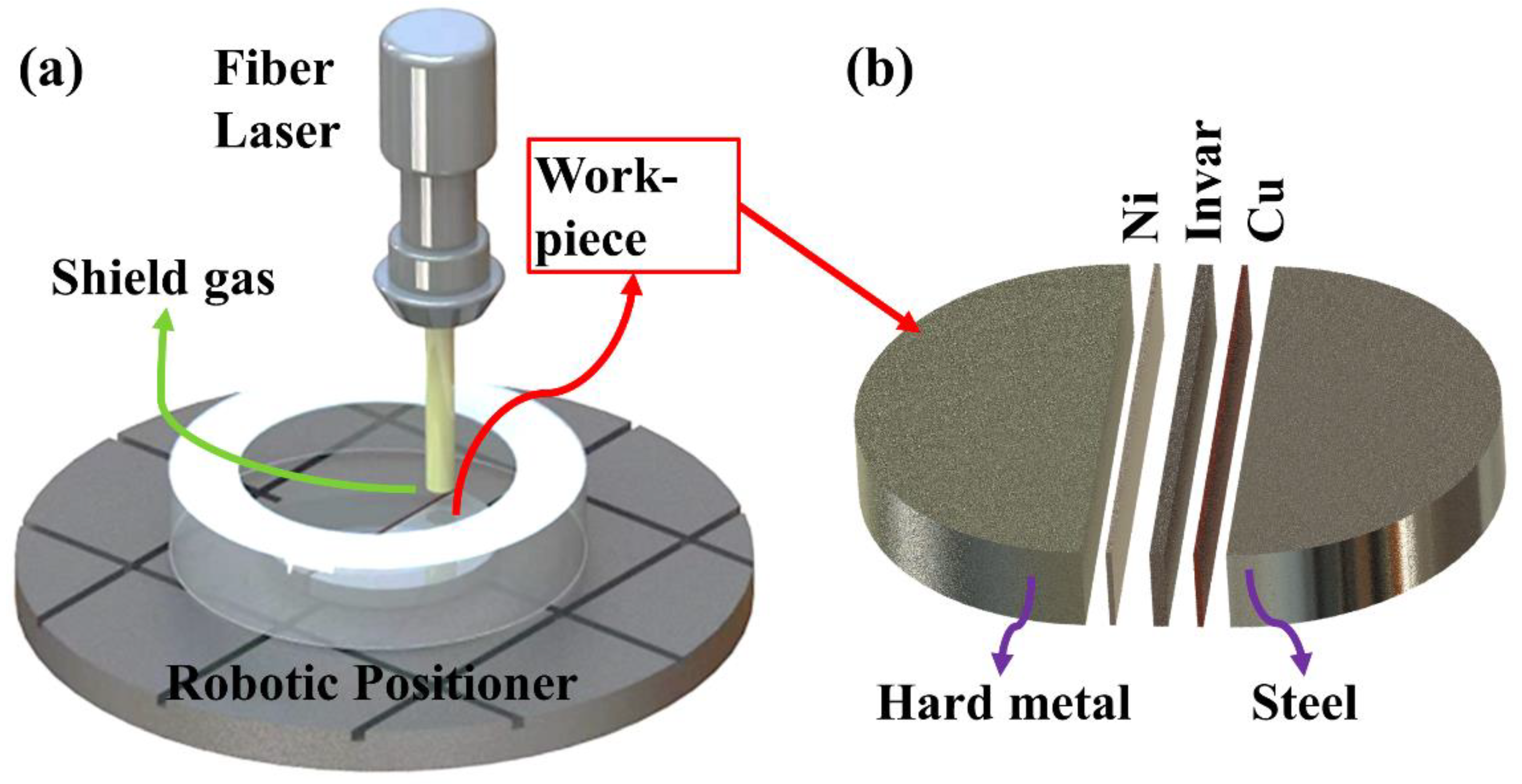
2.1. Experimental process

The WC-Co cemented carbide was selected as one of the base materials. The chemical composition is: 20Co, 4.9C, and 75.1W (wt. %). The other base material is S1045 carbon steel and it has the following chemical composition: 0.45C, 0.3Si, 0.62Mn, 0.03S, 0.03P, and balance Fe (wt. %). Pure copper, silver, nickel foils, and invar alloy were selected as brazing filler metals. Invar alloy has the following chemical composition: 42 wt. %Ni and 58 wt. %Fe.
The combinations of base materials and brazing filler metals are shown in Figure 1. The gap between base-materials were overfilled with a surplus pre-placed filler material. The thickness of a copper, silver, or nickel foil is 0.1 mm. Brazing filler metals consist of one or several foils. While using Cu/Invar/Ni as brazing filler metal, invar with three thicknesses of 1.0 mm, 1.5 mm, and 2.0 mm was placed in the middle. Copper is near to steel, and nickel spread on the cemented carbide side.
Electro Discharge Machining (EDM) was used to produce base materials and invar filler. A 4-mm-thick disc-shaped base materials with a 53 mm diameter were brushed to a 2 μm surface roughness finish. These base material discs were cut into halves and clamped to form a cemented carbide to steel butt joint with pre-placed brazing filler metals in between. All specimens were ultrasonic cleaned using ultrasonic cleaner before brazing.
Laser welding-brazing was conducted in a box in inert environments using a 5-kW maximum output YLS-5000 fiber laser (IPG, Oxford, MA, USA) with a KR60-HA robot (KUKA, Augsburg, Germany) and a BIMO QBH laser processing head (HIGHYAG, Kleinmachnow, Germany), welding positioner with welding jig, and gas supply. Inert laser welding-brazing was achieved with a high-purity argon gas at a flow rate of 25 L/min. Figure 1a illustrates the experimental architecture used in this study. The arrangement of one of the brazing filler metals is shown in Figure 1b. An inert environment eliminates the potential for oxidation of braze and braze components. The processes for laser welding-brazing are shown in Table 1. Following welding, the welded joints were evaluated for bead formation, incomplete fusion, or possible cracks. HXD-1000-type hardness tester (Taiming, Shanghai, China) were used to investigate the microhardness distribution (HV), using a load of 200 g and a holding time of 15 s.
The metallographic samples were first etched using a reagent consisting of 100 mL HCl, 2 g CuCl2, 7 g FeCl3, 5 mL HNO3, 200 mL CH3OH, and 100 mL H2O. Then tungsten carbide and mixed carbide was etched with Murakami’s reagent.
The microstructure of the laser welds was characterized by optical microscopy, electron probe microanalysis (EPMA), field emission scanning electron microscopy (FESEM). The FESEM and EPMA technique was used to determine the elemental distribution across the brazed joints using ZEISS Gemini 300 Scanning Electron Microscope (ZEISS, Oberkochen, Germany) and Oxford Xplore Energy Spectrometer, where the metallurgical reaction leads to the bonding and the mixed carbide formation.

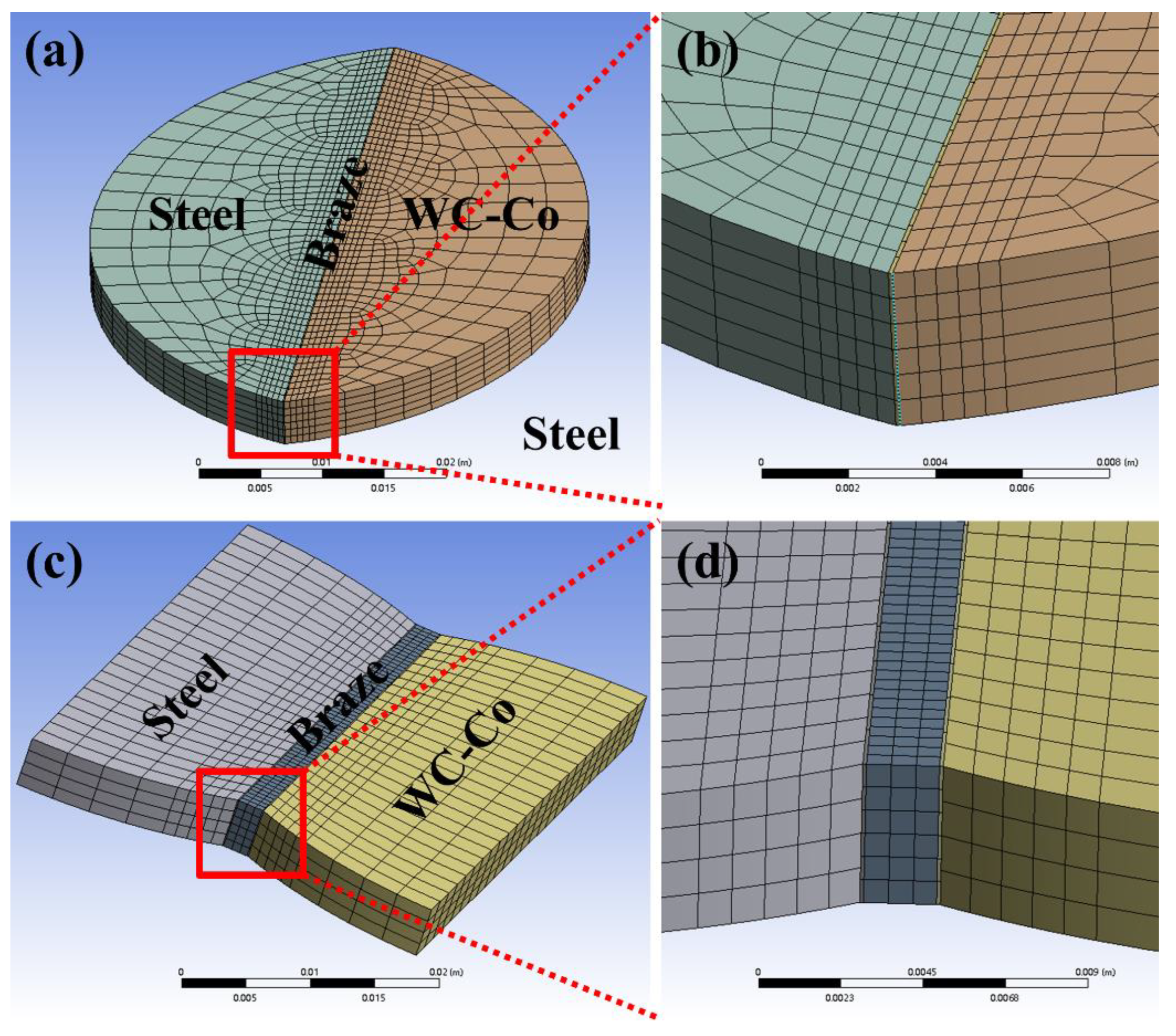
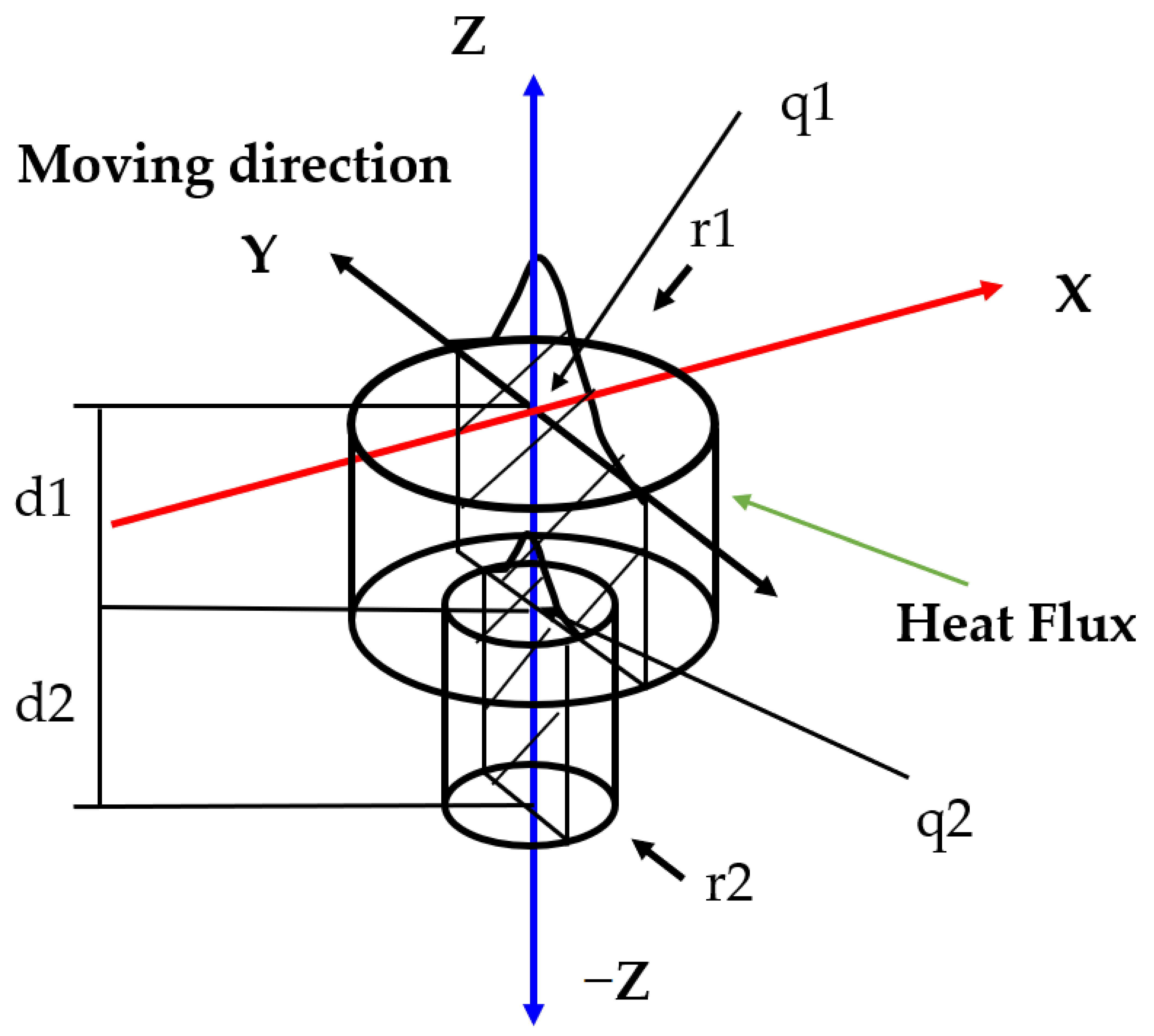
2.2. Finite Element Modelling

In order to investigate the distribution of residual stresses in welded joints, finite element numerical simulation was applied to simulate the temperature field distribution and residual stresses in welded joints using the software.
Figure 2 shows the mesh division in the finite element model. The mesh division is done by multi−regional division approach, with a narrow and dense mesh along the weld seam and a coarser mesh for the areas away from the seam. The area away from the weld seam is less affected by the heat source during the welding process, and such a mesh division can effectively improve the calculation efficiency. The finite element models for both the single and triple brazing specimens use the 20-node hexahedral element SOLID90. All meshes are bonded together to ensure that any errors in the non-positive stiffness matrix are avoided. It has the ability to simulate different welding conditions by varying various parameters, including dimensions, material properties and welding parameters.
As the materials used in this study are all common materials, their thermophysical property parameters can be retrieved directly from the simulation software material database.
The simulation of the laser welding process is implemented in the APDL language of the finite element analysis software (2020R2, ANSYS, Canonsburg, PA, USA), with a Gaussian stepped cylindrical heat source in the form of heat flow density, loaded on the nodes of the unit body. A sketch of the model is shown in Figure 3, with the top half of the heat source model described as follows:
q 1 ( x , y , z , t ) = Ql π r 1 2 d 1 exp ( x 2 + ( y γ t ) 2 r 1 2 ) U ( z )
The second half of the heat source model is described as follows:
q 2 ( x , y , z , t ) = Ql π r 2 2 d 2 exp ( x 2 + ( y γ t ) 2 r 2 2 ) U ( z )
where Ql is the heat source input power, γ is the welding speed and r1, r2, d1, d2 are the heat source shape factors.

3. Results and Discussion

3.1. Weld Formation

The weld penetration and bead formation are affected by brazing filler metals and welding parameters. Figure 4 shows a typical example diagram of the effect of welding speed on weld penetration and bead formation when using nickel as a brazing material. The laser spot focuses on the middle brazing filler metals between cemented carbide and carbon steel. The defocusing amount of laser was found to influence the fusion of dissimilar materials. The results indicated that specimens using defocusing amount −3 mm below surface obtained better joint penetration in contrast with other specimens. Therefore, all welding trials were conducted with a −3 mm defocused laser spot on the brazing filler metals.
Effect of thickness of brazing filler metal (silver) on the cross-sectional images (laser power 1.2 kW, and welding speed 0.1 m/s) was shown in Figure 5. Figure 5a–c illustrated the specimen B1, B2, and B3 respectively. When the thickness is 0.5 mm, the size of underfill is 0.9 mm, the weld width on the back side is 0.36 mm. If the thickness was decreased to 0.3 mm or 0.1 mm, and complete penetration with good formation can be obtained. The side of underfill decreased to 0.8 mm and 0.4 mm. The weld width on the back side increased to 0.5 mm and 1.2 mm. Because of the decrease of thickness, heat input is enough to melt the brazing filler metal and the part of the base materials. Therefore, the decrease of thickness of brazing filler metal silver is helpful to the weld penetration.
As shown in Figure 5d, cross-sectional image of a typical joint of steel and cemented carbide using copper as filler metal (specimen A4) showed the nail-head shaped as-welded fusion zone with a smooth top and root formation. The steel has a greater dilution than cemented carbide. In the middle of the cross-section, the width of fusion zone is nearly equal to that of original pre-placed copper. The image exhibited a typical keyhole between steel and cemented carbide (as indicated by yellow square dot line).
When using nickel as brazing filler metal, cross-sectional image of a typical joint C2 is shown in Figure 5. The typical joint has a smooth top and root formation. In comparison with specimen B2 using silver as brazing filler metal, there is greater dilution from steel side in specimen C2 (Figure 5e). However, on the WC-Co side, the base material melts insignificantly and only a small amount of tungsten carbide and cobalt diffuses into the weld area. The WC-Co side of specimen A4 melts more and more tungsten carbide and cobalt diffuses into the weld compared to C2. Molten nickel brazing filler metal flows into steel side. The nickel and both parent materials are metallurgically compatible. So, nickel brazing filler metal (all other parameters kept the same) has good compatibility with cemented carbide and steel.
In contrast, a typical joint in Figure 5f (specimen V2) consists of un-melted cemented carbide/fusion zone interface, molten Cu/Invar/Ni brazing filler metal, and molten steels. The cross-sectional image exhibited the nail-head shaped joint with a smooth top and root formation, which has laser welding-brazing characteristics relevant to understanding the welding mechanism of cemented carbide and steel. Face reinforcement and root reinforcement (yellow square dot) are 1.3 and 0.8 mm. Pre-placed Cu/Invar/Ni (blue square dot) and molten steel (red square dot) are large part of the fusion zone. With the increase of Cu/Invar/Ni thickness to 2 mm, it becomes difficult to join the WC-Co cemented carbide to steel using the current welding setup. Fast welding speed or thick interlayer led to such problems as insufficient root penetration and WC dissolution. Therefore, for 4- mm WC-Co and S1045 steel laser welding-brazing using Cu/Invar/Ni as brazing filler metal, it is recommended to use a fiber laser power in the range of 1.7 to 2.0 kW, and welding speed in the range of 0.08 to 0.15 m/s.

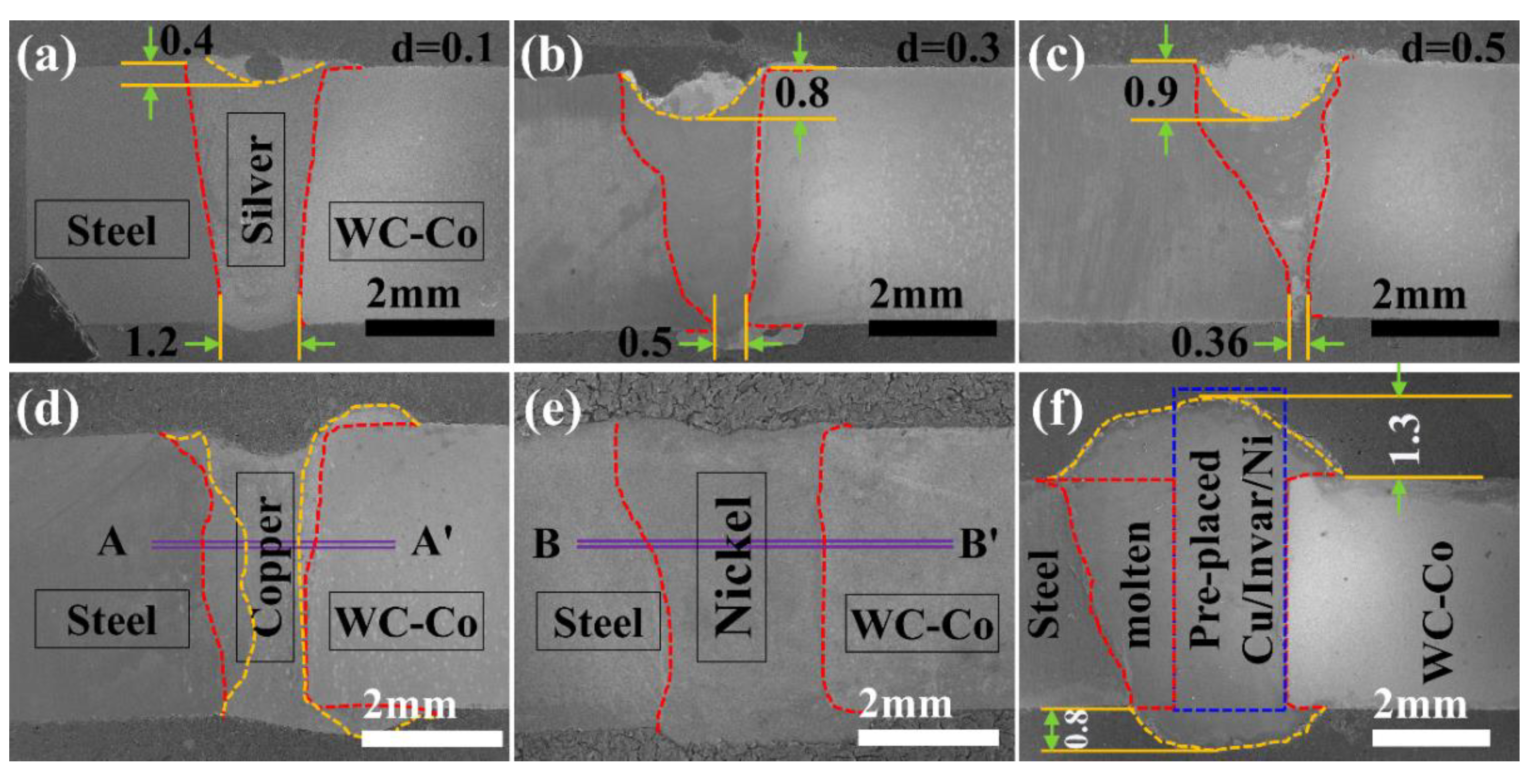
3.1.1. The Effect of Thickness of Brazing Filler Metal on the Weld Formation

Figure 6 shows the formation of welded joints with different types and thicknesses of brazing material. Using 0.3 mm thickness of copper as the brazing filler metal, the post-weld cracking was unable to make samples for analysis, so it was no longer considered. The results indicate: if the thickness (Specimen A2) is 0.2 mm, a good weld formation on the front side and a full penetration of weld bead on the back side were obtained. However, when the thickness is 0.1 mm, due to poor gap bridging ability, copper spread unevenly on the front side and insufficient penetration was observed at the end of the weld. When the thickness is 0.5 mm, as-welded joints have a wider seam on the front side. As the melting point of copper (Approx. 1083 °C) is much lower than that of carbon steel (Approx. 1435 °C), more copper spread to the back side. Which leads to poor penetration at the start point.
When the silver thickness is 0.1 mm, the insufficient silver causes depression on the front side and poor penetration on the back side. There is weld spatter on the cemented carbide side. More weld spatter was also observed on the carbon steel side. However, as the silver thickness increased, enough silver filled the weld seam thoroughly. With these specimens, the silver did not diffuse thoroughly on the backside. There is a low weld spatter on the backside.
Specimens with nickel brazing filler metal have a better penetration than those with copper or silver brazing filler metal. All specimens with nickel brazed filler metal had low weld spatter on both the front and back sides. When thickness of brazing filler metal is 0.1 mm, it can be observed that as-welded joint has good weld formation on the front side. It also can be found that the brazing filler metal in the middle is not fully melted due to poor gap bridging ability. When thickness is 0.3 mm, there exists un-melted metal at the end of the seam. The specimen has consistently better penetration on the back side. When thickness increases to 0.5 mm, depressions are observed at the start in the front weld. It can be observed from the back side of the weld that brazing filler metals are evenly melted throughout the seam.
During the laser welding-brazing of cemented carbide and carbon steel, larger or smaller thickness led to poor penetration on the back side. The thickness is determined by the heat input, thickness of base materials, and gap bridging ability of process. Under a certain amount of heat input, if the thickness of brazing filler metal is too big, the heat input is too low to melt the brazing filler metal far from the laser spot. Which leads to the poor weld penetration on the back side. If the thickness is too small, insufficient brazing filler metal spreads on the top surface because of the impact of laser.
Subsequently, using Cu/Invar/Ni (different thick Invar) as brazing filler metals, as-welded joint of cemented carbide and steel were prepared using laser welding-brazing when laser power and welding speed were 1.7 kW and 0.1 m/s. Among three brazing filler metals Cu/Invar/Ni, thickness of Invar varies from 1.0, 1.5, to 2.0 mm and copper and nickel foils are equal to 0.1 mm. Compared to brazing filler metals: copper, silver and nickel, complete joint penetration is obtained throughout the weld using Cu/Invar/Ni.

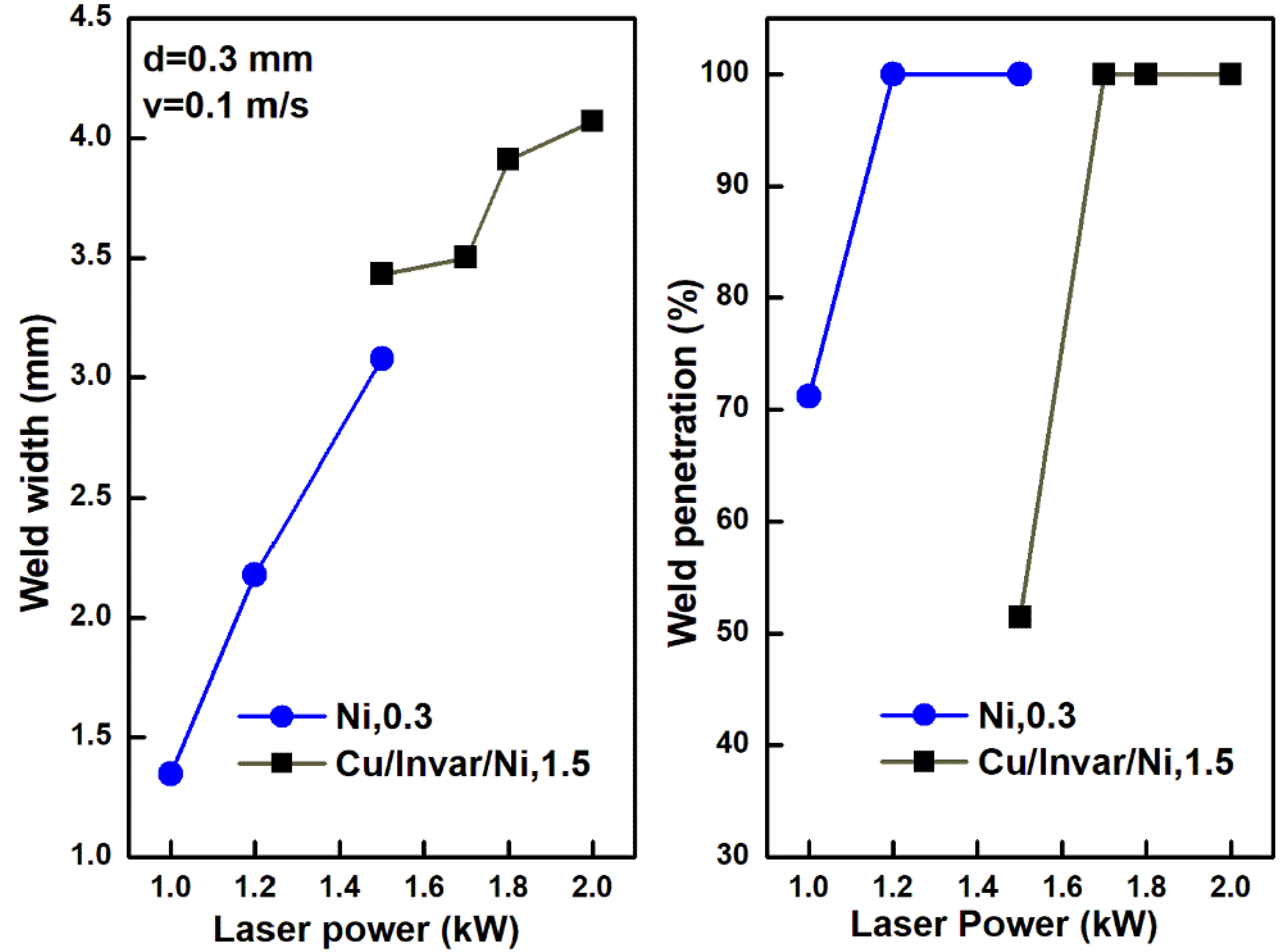
3.1.2. The Effect of Laser Power on the Weld Formation

The effect of laser power on weld formation and weld penetration is shown in Figure 7. If laser power is 1.0 kW (specimen C4), a good weld formation on the front side but a poor penetration of weld bead on the back side were obtained. Insufficient penetration was observed on the WC-Co side at the end of the weld. While complete joint penetration was obtained with increased laser power to 1.2 kW (Specimen C2). However, when laser power increased to 1.5 kW, cracks initiated and propagated near the weld on the WC-Co side at the end of the weld. Low laser power led to failure to achieve the minimum penetration and lack of WC-Co side wall fusion. Too high laser power caused cracks. Therefore, laser power 1.2 kW was appropriate for the current application.
When using 0.1/2/0.1 mm thick Cu/Invar/Ni as brazing filler metal with a laser power of 1.5 kW (specimen V4), a lack of penetration was observed throughout the weld seam on the back side. Lack of fusion was observed at the beginning and end of the weld. Excess weld metal was observed on the face of a butt. With increased laser power to 1.7 kW (specimen V2), 1.8 kW (specimen V5), and 2.0 kW (specimen V6), sufficient root penetration was obtained.

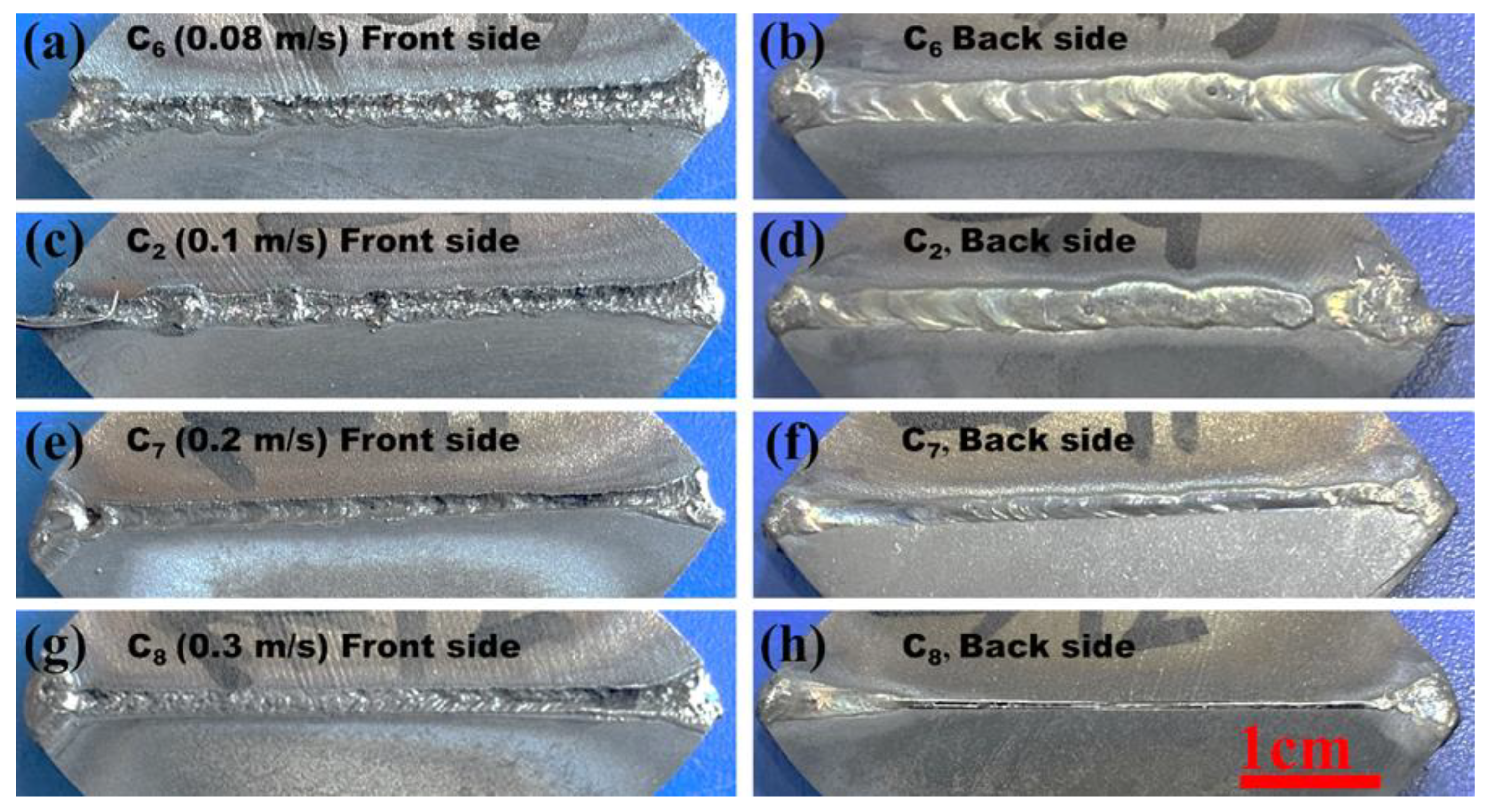
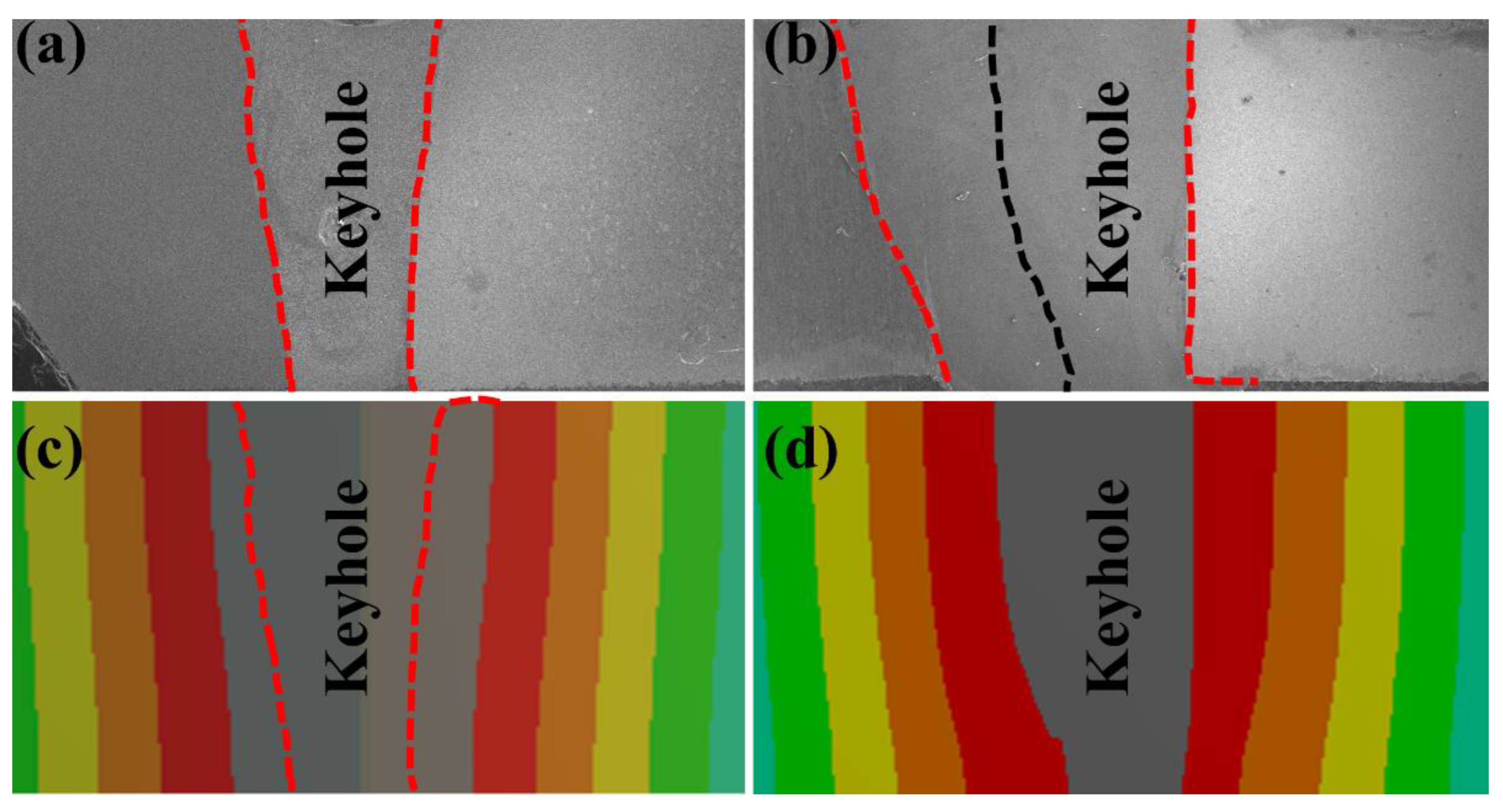
3.1.3. The Effect of Welding Speed on the Weld Formation

Figure 8 shows very significantly the effect of welding speed on weld width and weld penetration, as the welding speed increases, the weld width increases and the weld penetration is more complete. With a laser power of 1.2 kW, specimens C6, C2 and C7 were completely penetrated and no cracks were observed. Therefore, when using 0.3-mm-thick nickel as brazing filler metal, it is recommended to use a welding speed in the range of 0.1 to 0.2 m/s.
Excellent weld formation was obtained on the front side and complete penetration of the bead on the back side for specimens filled with Cu/Invar/Ni at welding speed of 0.08 m/s (specimen V7) and 0.1 m/s (specimen V3). At welding speed of 0.15 m/s (specimen V8) and 0.2 m/s (specimen V9), significant over-reinforcement was observed on the surface. Within the range of parameter variations in this study, it seems that for a constant laser power, decreasing the welding speed has a great effect on enhancing the penetration.

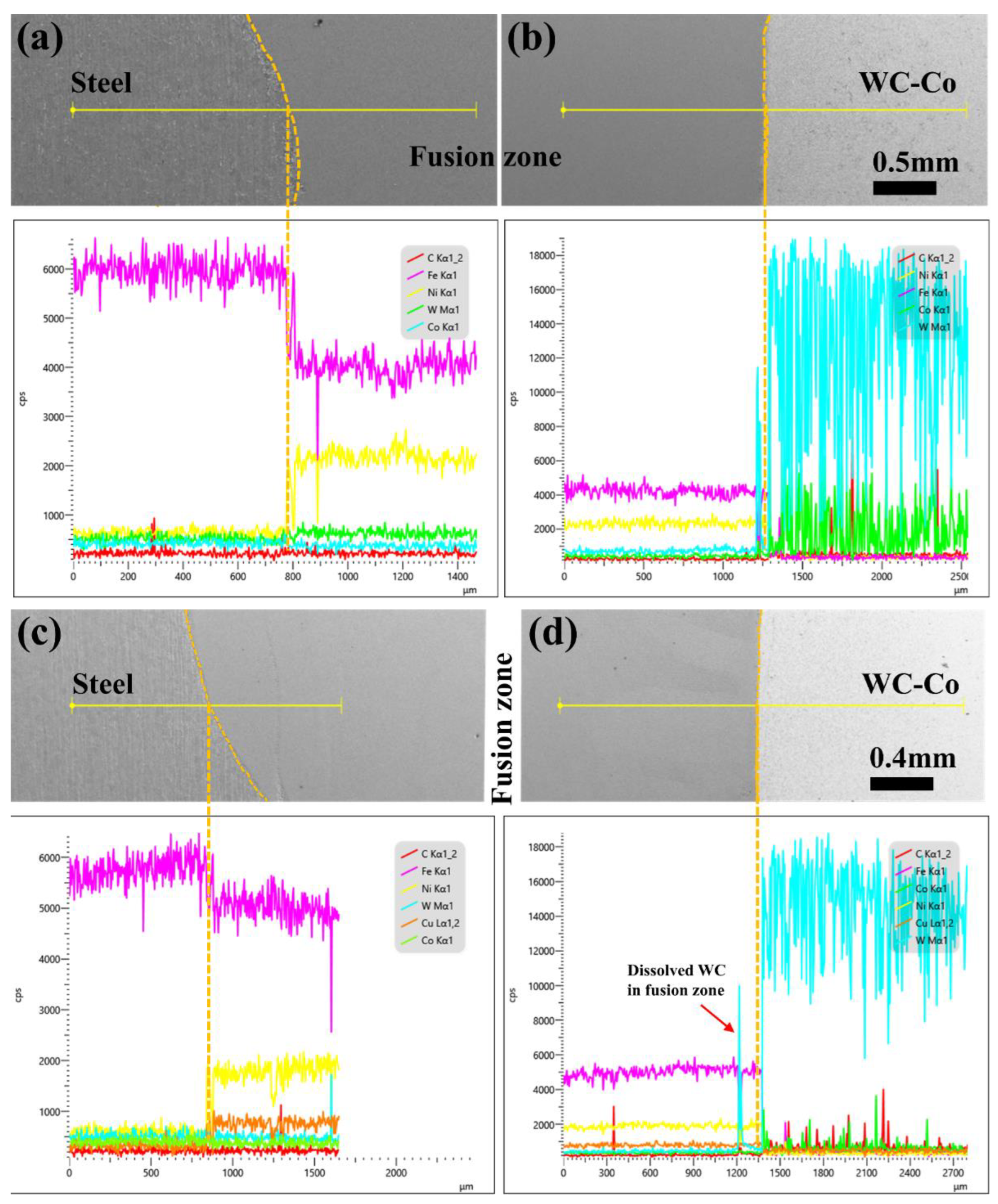
3.2. Element Diffusion at Interface

Figure 9a,b illustrates the elemental diffusion in specimen C2. According to the scan results, Fe, Ni, W, Co and C are the main elements throughout the welded joint. Element iron (purple lines) diffuses obviously at the S1045/Fusion Zone interface and the Fusion Zone/WC-Co interface. The results indicated that iron element in S1045 steel was slightly higher than that in the fusion zone, but iron content in the fusion zone was much higher than that in the WC-Co zone. Near WC-Co side, iron-rich phase was found, as shown by red arrow. High iron in W-Co-C system leads to ƞ phase formation, which enhanced diffusion of iron atom from fusion zone to WC-Co side. With the increase of the thickness of brazing filler metal, the gradient of iron at the S1045/Fusion zone interface increases, but decreases at the Fusion zone/WC-Co interface due to the decrease of penetration ratio on the steel side. Nickel in the fusion zone (yellow lines) increased rapidly with increased interlayer’s thickness, which is much higher than that in steel and WC-Co cemented carbide. Cobalt and tungsten were found to diffuse across Fusion zone/WC-Co interface. When all parameters kept the same, except the thickness of brazing filler metals being increased from 0.1 mm, 0.3 mm to 0.5 mm, the diffusion distance of cobalt and tungsten decreased accordingly. The results also showed that tungsten content in the fusion zone was higher than that in the S1045 steel. Within the range of thickness in the current research, it seems that for constant laser power and welding speed, increasing the thickness of brazing filler metal is beneficial to the dissolution of tungsten carbide and cobalt in the fusion zone.
In contrast, for V1, V2 and V3, when Cu/Invar/Ni is used as brazing filler metal, the melting on the steel side is greater than that on the WC-Co side. At the interface on steel side, all three specimens have smooth, continuous scanning elemental curves, steel side having more irons than that in the fusion zone, without showing any defects. In the fusion zone, nickel, copper, and tungsten are higher than that on steel side. Specimen V2 At the interface on WC-Co side, specimens have smooth, continuous scanning elemental curves, WC-Co side having more tungsten and cobalt than that in the fusion zone—Figure 9c,d. The fusion boundary region showed the higher temperature border (TWC) and lower temperature border (TCo) in the transition layer (labeled by red arrows in Figure 9d. In all specimens with Ni as brazing material and with Cu/Invar/Ni as brazing material, iron diffusion into the WC-Co side. That means irons diffusion into WC-Co cemented carbide. It is also observed that tungsten diffusion into the fusion zone starting from higher temperature border, and cobalt from lower temperature border. Tungsten diffusion occurred even far from the fusion line in the fusion zone in specimen V2. The appearance of tungsten appears in the fusion zone indicated that a certain amount of tungsten diffused into the fusion zone and participated in the metallurgical reaction at the interface. Tungsten-depletion region exists at the interface of WC-Co side in sample V3, while tungsten peaks appear on both sides of the fusion line, indicating that discontinuous cracks occur in the heat-affected zone of WC-Co side. Therefore, when using Cu/Invar/Ni as brazing filler metals, the as-brazed joint without cracks and porosities was obtained in specimen V2. Full penetration with the increased Invar thickness became true. However, too thick Invar layer also causes defects such as incomplete fusion.

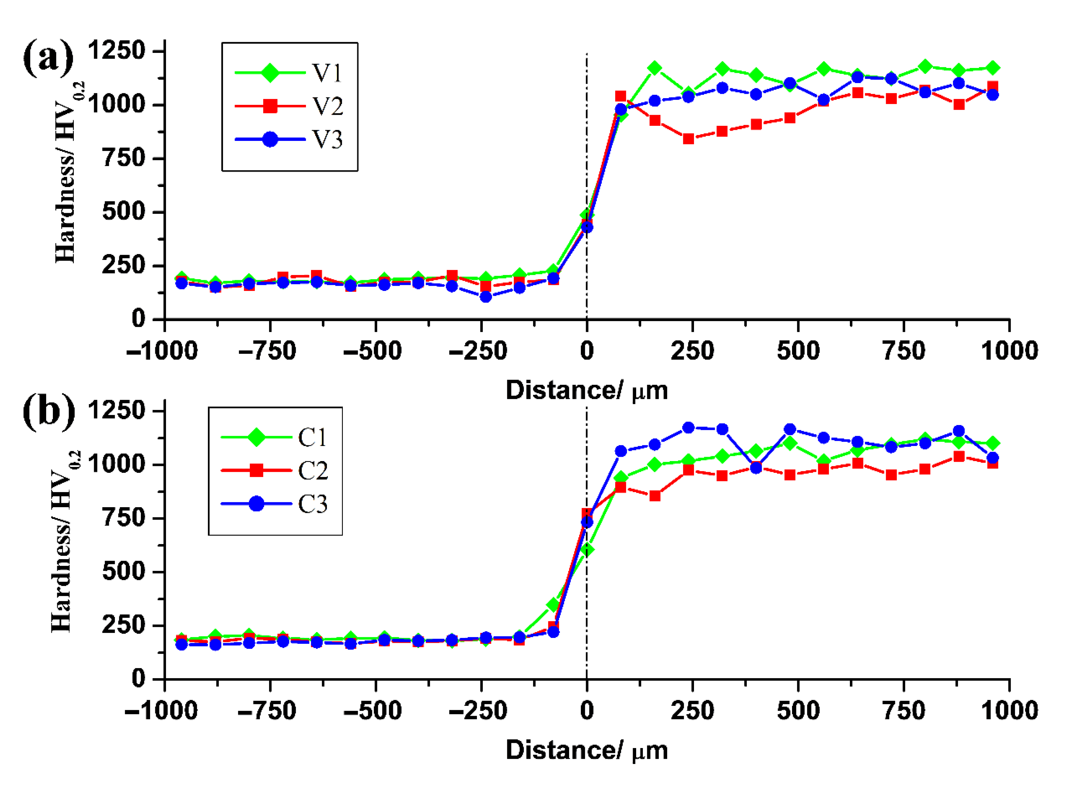
3.3. Hardness Measurements

Figure 10a shows the typical hardness distribution of a carbide to steel brazed joint. The fusion line on WC-Co side is set to be the origin of the graph. The average hardness ranges from 450 to 1127 HV, and drop to 186 HV in the fusion zone. At the origin, the hardness decreased from 488 to 429 HV through 445 HV with the increase of invar thickness due to the increased dilution. The smooth curve of hardness in the fusion zone indicated good metallurgical bonding of cemented carbide and carbon steels. Specimens C1, C2, and C3 (Figure 10b) follow the same rules. Hardness on WC-Co side is much higher than that in the fusion zones. Therefore, as-brazed joint with good metallurgical bonding can be obtained using the proposed brazing filler metals and welding processes.

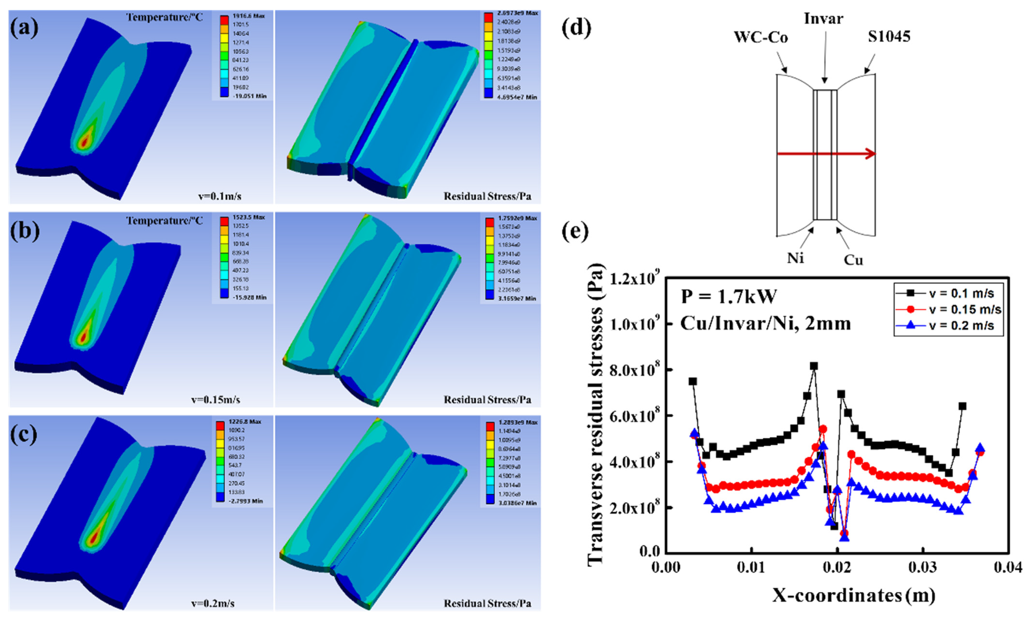
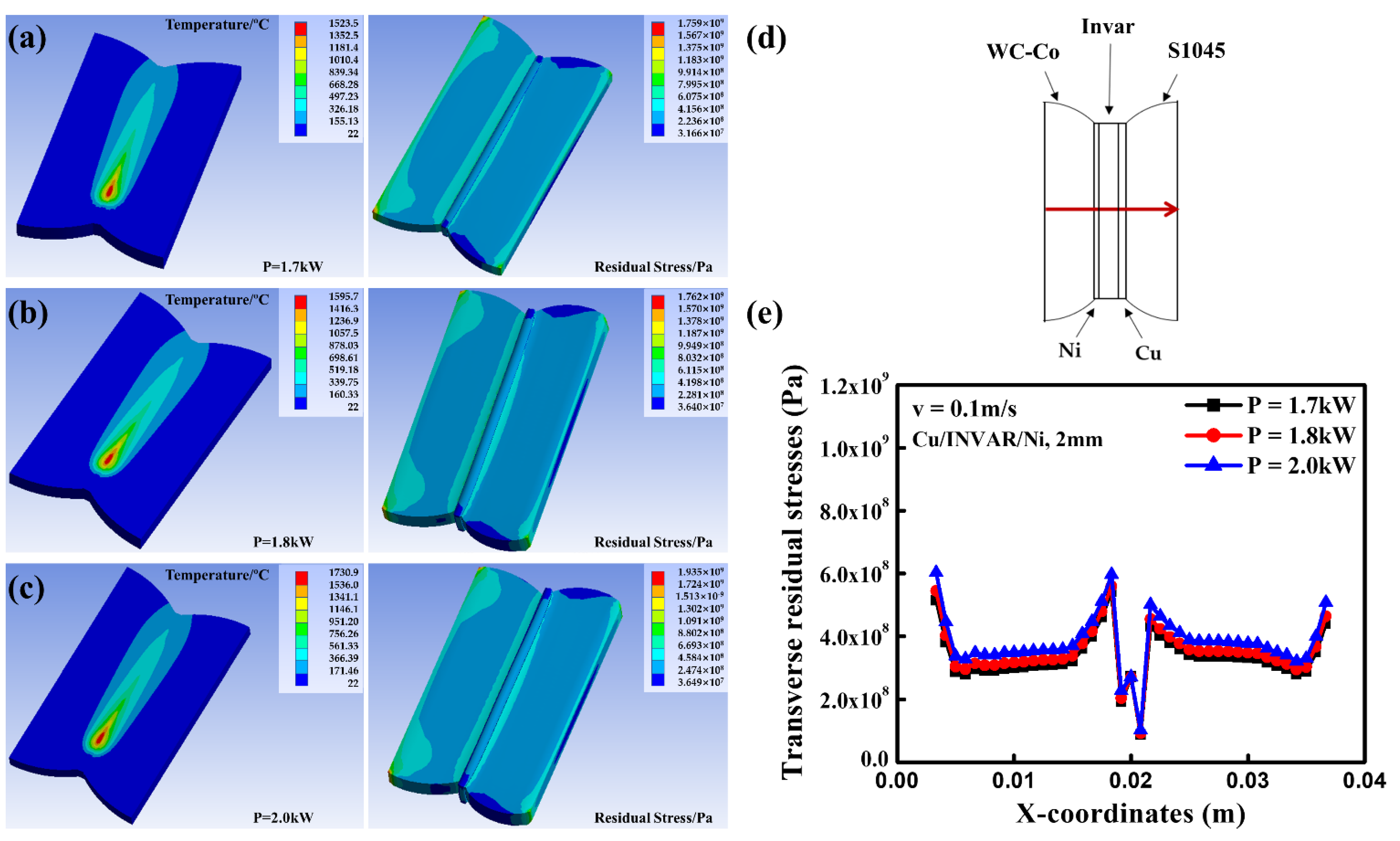
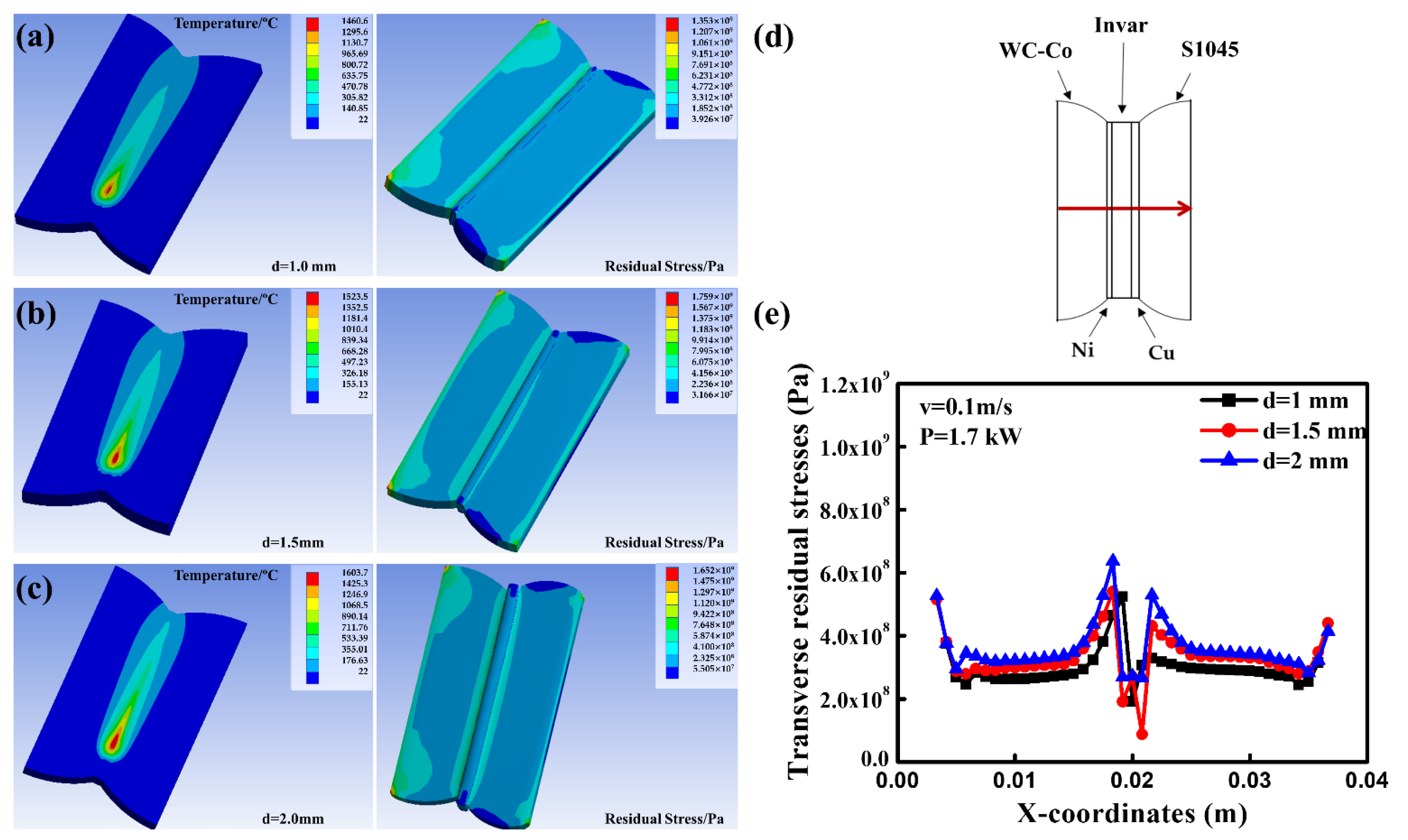
3.4. Temperature Field and Residual Stress

The macroscopic morphology, elemental diffusion, and hardness analysis of welded joints have been analyzed in the above work, but the existing studies cannot reflect the residual stress. In this work, the thermoelastic-plastic FEM is used to research the temperature variation, residual stresses and welding strain of as-welded joints.
The specimens with dramatic changes in shape during the experiments were selected for the temperature simulation. Figure 11a,b show the joint cross-sectional morphology of specimens B1 and V1 as derived from the finite element simulations and experiments respectively. Where the gray area represents the keyhole. The distribution of the simulated results is more consistent with the experimental results except for a small difference in the width of the braze melting region.
An accurate prediction of the size of the fusion zone is a prerequisite for suitable deformation and residual stresses during welding. Based on the comparison of the fusion zone morphology and experiment, it can be clearly seen that the heat source model and model parameters are reasonable and can accurately reflect the thermal cycle process of laser brazing. Therefore, the simulation results of the temperature field can be applied to the subsequent stress field.
The welding stresses are simulated in laser brazing processes. Figure 12 shows the contours of the transverse residual stress distribution on the mean cross section of the welds. Obviously, the transverse residual stress distribution is asymmetrical. The maximum joint amplitude for single-layer welds occurs at the interface between the weld and the base material. The maximum joint amplitude when Cu/Invar/Ni is used as brazing material occurs mainly on the side close to the carbide, with a small portion occurring on the side close to the steel. In this experiment, the brazing materials are heated to melt and diffusely melts, the yield strength and elastic modulus decrease to zero, and the thermal expansion of brazing materials are limited by the surrounding un-melted base material. During cooling, the un-melted steel and cemented carbide act as internal restraints to prevent shrinkage of the weld and the heat-affected zone, so that tensile residual stresses appear in the weld. Overall, the peak residual stresses in single-layer brazed joints are greater than those in triple-layer brazed joints.
The residual stresses near the weld interface are unstable because the coefficient of thermal expansion and the rate of cooling are different for different metal types at the interface, resulting in the generation of tensile stresses. This distribution of residual stresses also means that there is a heavy concentration of rain stresses and fracture is more likely to occur at the carbide side interface. This phenomenon coincides with the fracture condition in actual welding.
In order to investigate the effect of welding speed, laser power and braze thickness on the residual stresses in the welded joint, some simulations have been done as follows.
Figure 13 shows the distribution of the temperature fields and residual stress fields in the workpiece when the other process parameters are the same and only the welding scan speed differs. The distribution trend of transverse residual stresses in the welded joint is the same. The curves show the distribution of residual stresses over the central cross-section of the specimen. From left to right in the sequence of cemented carbide, Ni, Invar, Cu and S1045 steel, the residual stress is higher at the fixture and then decreases very rapidly, the residual stress is taught to be smooth in the base material; near the weld residual stress rises sharply and reaches a maximum at the interface between cemented carbide and Ni; the weld is well relieved by the presence of brazing material. As welding speed increases, the residual stress decreases accordingly.
Figure 14 shows the results of the simulation of the residual stress field for welded joints with the same other parameters at a power of 1.7 kW, 1.8 kW and 2.0 kW, respectively. As the laser power increases, the residual stress values in the welded joint increase. Figure 15 shows the increase in the transverse residual stresses in the weld joint with increasing thickness of the intermediate layer metal Invar alloy for the specimens with Cu/Invar/Ni brazing material.
As can be seen from the above analysis, the junction of different materials and the clamping area of the fixture is prone to greater residual stress; increased welding heat input will lead to increased welding residual stress; in the factors affecting the heat input of welding, the impact of welding speed on the residual stress of the as-welded joint is relatively large.

4. Conclusions

Using laser welding-brazing method, heterogeneous materials of WC-Co and S1045 carbon steel were successfully welded using nickel, copper, silver, and Cu/Invar/Ni brazing filler metals.
For 4-mm WC-Co and S1045 steel laser welding-brazing using 0.3 mm nickel as brazing filler metal, full penetration can be obtained with laser power of 1.2 kW and at a welding speed of 0.1 m/s. With increased laser power and decreased welding speed, weld width and weld penetration increase.
For 4-mm base materials using Cu/Invar/Ni as brazing filler metal, it is recommended to use a laser power in the range of 1.7 to 2.0 kW and welding speed in the range of 0.08 to 0.15 m/s. FEM results show: although a high welding speed (0.1 m/s) and increased laser power can be used to join cemented carbide WC-Co and steel, it is still a challenge to optimize laser power and welding speed for a given brazing filler metal.
Among the proposed brazing filler metals, nickel (all other parameters kept the same) has better compatibility with cemented carbide and steel. As-welded joint prepared using nickel as brazing filler metal can serve at an elevated temperature. Cu/Invar/Ni provides a wider buffer for cemented carbide and steels, however, this kind as-welded joint needs higher laser power for a given high welding speed.

Author Contributions

Methodology, S.M. and P.X.; software, S.M., B.L. and P.Z.; validation, Y.M. and S.M.; formal analysis, S.M.; investigation, S.M.; data curation, S.M.; writing—original draft preparation, S.M. and P.Z.; writing—review and editing, B.L., P.X., S.M. and P.Z.; supervision, P.X.; project administration, S.M., P.Z. All authors have read and agreed to the published version of the manuscript.

Funding

This research was funded by Natural Science Foundation of Shanghai (Grant number 20ZR1422700).

Conflicts of Interest

The authors declare no conflict of interest.

References

  1. Fang, Z.Z.; Wang, X.; Ryu, T.; Hwang, K.S.; Sohn, H.Y. Synthesis, sintering, and mechanical properties of nanocrystalline cemented tungsten carbide. Int. J. Refract. Met. Hard Mater. 2009, 27, 288–299. [Google Scholar] [CrossRef]
  2. García, J.; Ciprés, V.C.; Blomqvist, A.; Kaplan, B. Cemented carbide microstructures. Int. J. Refract. Met. Hard Mater. 2019, 80, 40–68. [Google Scholar] [CrossRef]
  3. Yin, G.; Wang, Y.; Cui, H.; Lu, F.; Xu, P. Effect of holding time and interlayer’s thickness on the crack initiation and propagation and the dissolving behavior of the heat affected facet WC grains. Int. J. Refract. Met. Hard Mater. 2018, 71, 45–60. [Google Scholar] [CrossRef]
  4. Jiang, W.; Lu, H.; Chen, J.; Liu, X.; Liu, C.; Song, X. Toughening cemented carbides by phase transformation of zirconia. Mater. Des. 2021, 202, 109559. [Google Scholar] [CrossRef]
  5. Hayashi, T.; Sato, F.; Sasaya, K.; Ikegaya, A. Industrialization of tungsten recovering from used cemented carbide tools. SEI Technol. Rev. 2016, 82, 33–38. [Google Scholar]
  6. Xu, P.Q.; Ren, J.W.; Zhang, P.L.; Gong, H.Y.; Yang, S.L. Analysis of formation and interfacial WC dissolution behavior of WC-Co/Invar laser-TIG welded joints. J. Mater. Eng. Perform. 2013, 22, 613–623. [Google Scholar] [CrossRef]
  7. Sharma, N.K.; Kannan, R.; Hogan, J.; Fisher, G.; Li, L. Progress in improving joint strength of brazed cemented carbides and steels. Sci. Technol. Weld. Join. 2021, 26, 420–437. [Google Scholar] [CrossRef]
  8. Ma, B.; Wang, X.; Chen, C.; Zhou, D.; Xu, P.; Zhao, X. Dissimilar welding and joining of cemented carbides. Metals 2019, 9, 1161. [Google Scholar] [CrossRef] [Green Version]
  9. Yin, G.; Xu, P.; Gong, H.; Cui, H.; Lu, F. Effect of interlayer thickness on the microstructure and strength of WC-Co/ Invar/316L steel joints prepared by fiber laser welding. J. Mater. Process. Technol. 2018, 255, 319–332. [Google Scholar] [CrossRef]
  10. Mirski, Z.; Granat, K.; Stano, S. Possibilities of laser-beam joining cemented carbides to steel. Weld. Int. 2016, 30, 187–191. [Google Scholar] [CrossRef]
  11. Rodelas, J.; Hilmas, G.; Mishra, R.S. Sinterbonding cobalt-cemented tungsten carbide to tungsten heavy alloys. Int. J. Refract. Met. Hard Mater. 2009, 27, 835. [Google Scholar] [CrossRef]
  12. Wang, X.; Zhou, D.; Xu, P. The WC-Co/Fe-Ni interface: Effect of holding time on the microstructure, grain size and grain growth mechanism. Ceram. Int. 2019, 45, 23320. [Google Scholar] [CrossRef]
  13. Yared, W.; Chen, C.Y.; Sievers, N.; Tillmann, W.; Zielke, R.; Schimpfermann, M. Void distribution in a brazed cemented carbide steel joint analyzed by X-ray microscopy. Measurement 2019, 141, 250–257. [Google Scholar] [CrossRef]
  14. Xiao, Y.H.; Liu, P.W.; Wang, Z.; Wang, Y.; Feng, K.Q.; Chen, L. La2O3 addition for improving the brazed joints of WC-Co/1Cr13. J. Mater. Process. Technol. 2019, 267, 17–25. [Google Scholar] [CrossRef]
  15. Fukae, K.; Yamanishi, T.; Hirose, K.; Imamura, S. Coated cermet grade T2500Z for steel turning. SEI. Tech. Rev. 2020, 90, 86. [Google Scholar]
  16. Maizza, G.; Pero, R.; De Marco, F.; Ohmura, T. Correlation between the indentation properties and microstructure of dis-similar capacitor discharge welded WC-Co/high-speed steel joints. Materials 2020, 13, 2657. [Google Scholar] [CrossRef]
  17. Xian, G.; Xiong, J.; Zhao, H.; Fan, H.; Li, Z.; Du, H. Evaluation of the structure and properties of the hard TiAlN-(TiAlN/CrAlSiN)-TiAlN multiple coatings deposited on different substrate materials. Int. J. Refract. Met. Hard Mater. 2019, 85, 105056. [Google Scholar] [CrossRef]
  18. Gilliland, R.G.; Adams, C.M. Improved brazing methods for tungsten carbide tool bits. Weld. J. 1971, 50, S267. [Google Scholar]
  19. Samoylov, V.S. A technique for determination of strength of welds of hard alloy-steel prepared by diffusion welding in vacuum. Elektron. Obrab. Mater. 1973, 39, 742–748. [Google Scholar]
  20. Gerasimenko, K.S.; Spirina, S.I. Experiment of diffusion welding of hard alloys. Powder Metall. Met. Ceram. 1967, 6, 676–679. [Google Scholar] [CrossRef]
  21. Zhao, X.J.; Liu, P.T.; Chen, C.H.; Yang, D.X.; Kohsuke, T. η Phase formation mechanism at cemented carbide YG30/Steel 1045 joints during Tungsten-Inert-Gas Arc welding. Mater. Sci. Forum. 2011, 675, 901–904. [Google Scholar] [CrossRef]
  22. Okita, K.; Aritoshi, M.; Kuwabara, K.; Matsui, M.; Takami, C.; Kajino, H.; Tsuda, K. Friction welding of cemented carbide alloy to tool steel. Weld. Int. 1997, 11, 257–263. [Google Scholar] [CrossRef]
  23. Tian, N.; Yang, Y. Study of laser molten welding of cemented carbides and steel. In Proceedings of the Laser Processing of Materials and Industrial Applications 1996; SPIE: Bellingham, WA, USA, 1996; Volume 2888, p. 185. [Google Scholar]
  24. Thorsen, K.A.; Fordsmand, H.; Praestgaard, P.L. An explanation of wettability problems when brazing cemented carbides. Weld. J. 1984, 63, 308. [Google Scholar]
  25. Avettand-Fènoël, M.N.; Nagaoka, T.; Fujii, H.; Taillard, R. Characterization of WC/12Co cermet-steel dissimilar friction stirs welds. J Manuf. Process. 2018, 31, 139–155. [Google Scholar] [CrossRef]
  26. Feng, K.; Chen, H.; Xiong, J.; Guo, Z. Investigation on diffusion bonding of functionally graded WC–Co/Ni composite and stainless steel. Mater. Des. 2013, 46, 622–626. [Google Scholar] [CrossRef]
  27. Cheniti, B.; Miroud, D.; Badji, R.; Allou, D.; Csanádi, T.; Fides, M.; Hvizdoš, P. Effect of brazing current on microstructure and mechanical behavior of WC-Co/AISI 1020 steel TIG brazed joint. Int. J. Refract. Met. Hard Mater. 2017, 64, 210–218. [Google Scholar] [CrossRef]
  28. Wang, H.; Yang, D.; Zhao, X.; Chen, C.; Wang, Q. Microstructure and bend strength of WC–Co and steel joints. Sci. Technol. Weld. Join. 2005, 10, 167–168. [Google Scholar] [CrossRef]
  29. Maizza, G.; Cagliero, R.; Lacobone, A.; Montanari, R.; Varone, A.; Mezzi, A.; Kaciulis, S. Study of steel-WC interface produced by solid-state capacitor discharge sinter-welding. Surf. Interface Anal. 2016, 48, 538–542. [Google Scholar] [CrossRef]
  30. Edin, E.; Blomqvist, A.; Lattemann, M.; Luo, W.; Ahuja, R. MD study of C diffusion in WC/W interfaces observed in cemented carbides. Int. J. Refract. Met. Hard Mater. 2019, 85, 105054. [Google Scholar] [CrossRef]
  31. Li, S.W.; Shi, J.M.; Xiong, J.T.; Peng, Y.; Ren, J.; Zhang, F.S.; Li, J.L. Microstructural characteristics and mechanical properties of WC-Co/steel joints diffusion bonded utilizing Ni interface. Ceram. Int. 2021, 47, 4446–4454. [Google Scholar] [CrossRef]
  32. Roulon, Z.; Lay, S.; Missiaen, J.M. Interface characteristics in cemented carbides with alternative binders. Int. J. Refract. Met. Hard Mater. 2020, 92, 105306. [Google Scholar] [CrossRef]
  33. Kurabayashi, K.; Tokita, S.; Sato, Y.S. Effect of Ni addition on the interfacial strength of Al/Cu dissimilar welds produced by friction stir lap welding. Metals 2022, 12, 453. [Google Scholar] [CrossRef]
  34. Chiocca, A.; Frendo, F.; Bertini, L. Evaluation of heat sources for the simulation of the temperature distribution in gas metal arc welded joints. Metals 2019, 9, 1142. [Google Scholar] [CrossRef] [Green Version]
  35. Du, D.; Liu, D.; Zhang, X.; Tang, J.; Meng, B. Effects of WC-17Co coating combined with shot peening treatment on fatigue behaviors of TC21 titanium alloy. Materials 2016, 9, 865. [Google Scholar] [CrossRef] [PubMed] [Green Version]
  36. Alipooramirabad, H.; Paradowska, A.; Reid, M.; Ghomashchi, R. Effects of PWHT on the residual stress and microstructure of Bisalloy 80 steel welds. Metals 2022, 12, 1569. [Google Scholar] [CrossRef]
  37. Yoshida, S.; Sasaki, T.; Usui, M.; Sakamoto, S.; Gurney, D.; Park, I.K. Residual stress analysis based on acoustic and optical methods. Materials 2016, 9, 112. [Google Scholar] [CrossRef] [Green Version]
  38. Wu, G.; Luo, J.; Li, L.; Long, Y.; Zhang, S.; Wang, Y.; Zhang, Y.; Xie, S. Control of welding residual stress in large storage tank by finite element method. Metals 2022, 12, 1502. [Google Scholar] [CrossRef]
  39. Xu, P.; Zhou, D.; Li, L. Fiber laser welding of WC-Co and carbon steel dissimilar materials. Weld. J. 2017, 96, 1–10. [Google Scholar]
Figure 1. (a) Experimental setup for laser welding-brazing robotic system. (b) Preplaced brazing filler metals between cemented carbide and steels.
Metals 12 01780 g001
Figure 2. Meshing of finite element model, (a,b): single-layer brazing model, (c,d): three-layer brazing model.
Metals 12 01780 g002
Figure 3. Stepped cylindrical Gaussian distribution model.
Metals 12 01780 g003
Figure 4. Effect of welding speed on the weld formation using 0.3-mm-thick nickel as brazing filler metal when laser power is 1.2 kW. Front side weld formation. (a) Specimen C6 (0.08 m/s), (c) Specimen C2 (0.1 m/s), (e) Specimen C7 (0.2 m/s), and (g) Specimen C8 (0.3 m/s). Back side weld formation. (b) Specimen C6, (d) Specimen C2, (f) Specimen C7, and (h) Specimen C8.
Metals 12 01780 g004
Figure 5. Cross-sectional view of a typical joint of S1045 (left side) and WC Co (right side) (a) Specimen B1, d = 0.1 mm, (b) Specimen B2, d = 0.3 mm, (c) Specimen B3, d = 0.5 mm, using silver as brazing filler metal. (d) Specimen A4, d = 0.5 mm, using copper as brazing filler metal. (e) Specimen C2, d = 0.3 mm, using nickel as brazing filler metal (f) Specimen V2, using Cu/Invar/Ni as brazing filler metal.
Metals 12 01780 g005
Figure 6. Weld width and weld penetration of four braze materials of different thicknesses.
Metals 12 01780 g006
Figure 7. Effect of laser power on the weld formation and weld penetration.
Metals 12 01780 g007
Figure 8. Effect of welding speed on the weld formation and weld penetration.
Metals 12 01780 g008
Figure 9. Line-scanning results for elements C, Fe, Co, Ni, and W diffusion near interface between WC-Co (right side) and steel (left side) with fusion zone in between in (a,b) specimen C3; (c,d) specimen V2.
Metals 12 01780 g009
Figure 10. Microhardness distribution trend at the weld of the specimen (a) V1, V2, and V3. (b) C1, C2, and C3.
Metals 12 01780 g010
Figure 11. Cross-section of brazed joint (a) B1 and (b) V1 obtained by experiment and (c,d) the corresponding simulation results.
Metals 12 01780 g011
Figure 12. Specimen C1 (a) Residual stress distribution, (b) Cross−sectional residual stress distribution, and specimen V1, (c) Residual stress distribution, (d) Cross−sectional residual stress distribution.
Metals 12 01780 g012
Figure 13. Simulation results of the temperature field and stress field for as−welded joints at welding speed of (a) 0.1 m/s, (b) 0.15 m/s, (c) 0.2 m/s, (d) Schematic diagram of residual stress simulation, (e) Comparison curve of residual stresses at different welding speeds.
Metals 12 01780 g013
Figure 14. Simulation results of temperature field and residual stress field when laser power of as-welded joint is equal to: (a) 1.7 kW, (b) 1.8 kW, (c) 2.0 kW, (d) Schematic diagram of residual stress simulation, (e) Comparison curve of residual stresses at different laser power.
Metals 12 01780 g014
Figure 15. Simulation results of temperature field and residual stresses field when the thickness of Invar is equal to: (a) 1 mm, (b) 1.5 mm, (c) 2 mm, (d) Schematic diagram of residual stress simulation, (e) Comparison curve of residual stress at different thickness of Invar.
Metals 12 01780 g015
Table 1. Laser welding-brazing parameters of cemented carbides and steels.
SpecimenLaser Power
P (kW)
Welding Speed
v (m/s)
Defocusing Amount (mm)Brazing Filler MetalThickness
d (mm)
A11.20.1−3Cu0.1
A21.20.1−3Cu0.2
A31.20.1−3Cu0.3
A41.20.1−3Cu0.5
B11.20.1−3Ag0.1
B21.20.1−3Ag0.3
B31.20.1−3Ag0.5
C11.20.1−3Ni0.1
C21.20.1−3Ni0.3
C31.20.1−3Ni0.5
C41.00.1−3Ni0.3
C51.50.1−3Ni0.3
C61.20.08−3Ni0.3
C71.20.2−3Ni0.3
C81.20.3−3Ni0.3
V11.70.1−3Cu/Invar/Ni0.1/1.0/0.1
V21.70.1−3Cu/Invar/Ni0.1/1.5/0.1
V31.70.1−3Cu/Invar/Ni0.1/2.0/0.1
V41.50.1−3Cu/Invar/Ni0.1/1.5/0.1
V51.80.1−3Cu/Invar/Ni0.1/1.5/0.1
V62.00.1−3Cu/Invar/Ni0.1/1.5/0.1
V71.70.08−3Cu/Invar/Ni0.1/2.0/0.1
V81.70.15−3Cu/Invar/Ni0.1/2.0/0.1
V91.70.2−3Cu/Invar/Ni0.1/2.0/0.1
Publisher’s Note: MDPI stays neutral with regard to jurisdictional claims in published maps and institutional affiliations.

