Article

Effect of Machining Conditions on Temperature and Vickers Microhardness of Chips during Planing

1
Faculty of Manufacturing Technologies with the Seat in Presov, Technical University of Kosice, Sturova 31, 080 01 Presov, Slovakia
2
Faculty of Technology, UTB Tomas Bata University in Zlin, Vavreckova 5669, 760 01 Zlin, Czech Republic
3
Faculty of Mechanical Engineering, VŠB-Technical University of Ostrava, 17. Listopadu 15/2172, 708 33 Ostrava-Poruba, Czech Republic
*
Author to whom correspondence should be addressed.
Metals 2022, 12(10), 1605; https://doi.org/10.3390/met12101605
Submission received: 27 August 2022 / Revised: 20 September 2022 / Accepted: 21 September 2022 / Published: 26 September 2022
(This article belongs to the Special Issue Machinability and Tribological Performance of Advanced Alloys)

Abstract

:
For the machining of long and narrow surfaces and when processing multiple pieces, planing technology is used, the productivity of which can be higher than that of milling, although it is relatively slow machining. The article aims to study the degree of influence of the geometry of the tool (the angle of cutting-edge inclination and the angle of the tool-orthogonal rake), as well as the cutting conditions (cutting depth and cutting speed) on the chip characteristics (temperature and microhardness) in orthogonal and oblique slow-rate machining of steel 1.0503 (EN C45). The experiments were carried out on specially prepared workpieces designed for immediate stopping of machining. The results of the experiments were statistically processed, and behavioural models were created for temperature and Vickers microhardness of chips for individual combinations of factors. The obtained dependencies revealed how the geometry of the cutting tool and the cutting conditions affect the temperature and microhardness in the cutting area and at the same time allowed the best conditions for both orthogonal and oblique machining to be set up.

1. Introduction

Cutting operations with relatively low cutting velocity include planing and broaching technologies. Planing is a cutting process in which the formed chip is visible to the eye, whereas in broaching, the chip generation process is hidden and invisible to the naked eye. Therefore, it is possible to monitor the development of the temperature field in the area of chip generation during planing with a temperature measuring device by laser aiming and thus providing an approximate idea of the temperature generated not only during cutting but also during broaching [1,2].
The planing process is one of the oldest among the so-called single-point machining processes, used in the production of long cuts. This type of machining technology uses a linear motion with a single-pointed cutting tool to create a flat surface. The cutting tool is clamped in the tilting head, which prevents damage to the cutting edge when returning the tool. Although the process seems to be easy, setting the cutting conditions is difficult [3,4,5,6].
During the planing, the workpiece moves linearly and is usually machined with one tool. Because the large, heavy workpiece and table are in motion at relatively low cutting speeds, planers come with several tool heads and multiple tools in one head [7]. In addition, many planers are constructed with tool heads to make cuts in both directions of table movement [8]. Nevertheless, as mentioned above, since only single-pointed tools and low cutting speeds are used, planing is classified as a low-productivity cutting process compared to other cutting methods. However, when machining long and narrow surfaces (such as guide rails, long grooves, etc.) and when cutting multiple pieces with a planer, the efficiency of this type of workpiece processing can be much higher compared to milling [9,10]. The planing accuracy can reach IT9~IT8 and the surface roughness can be in the range of Ra is 3.2~1.6 μm [11,12,13].
In spite of planing being considered an obsolete technology, for performing and observing experimental tests for machining at relatively low cutting speeds, planing appears to be a very attractive machining process [
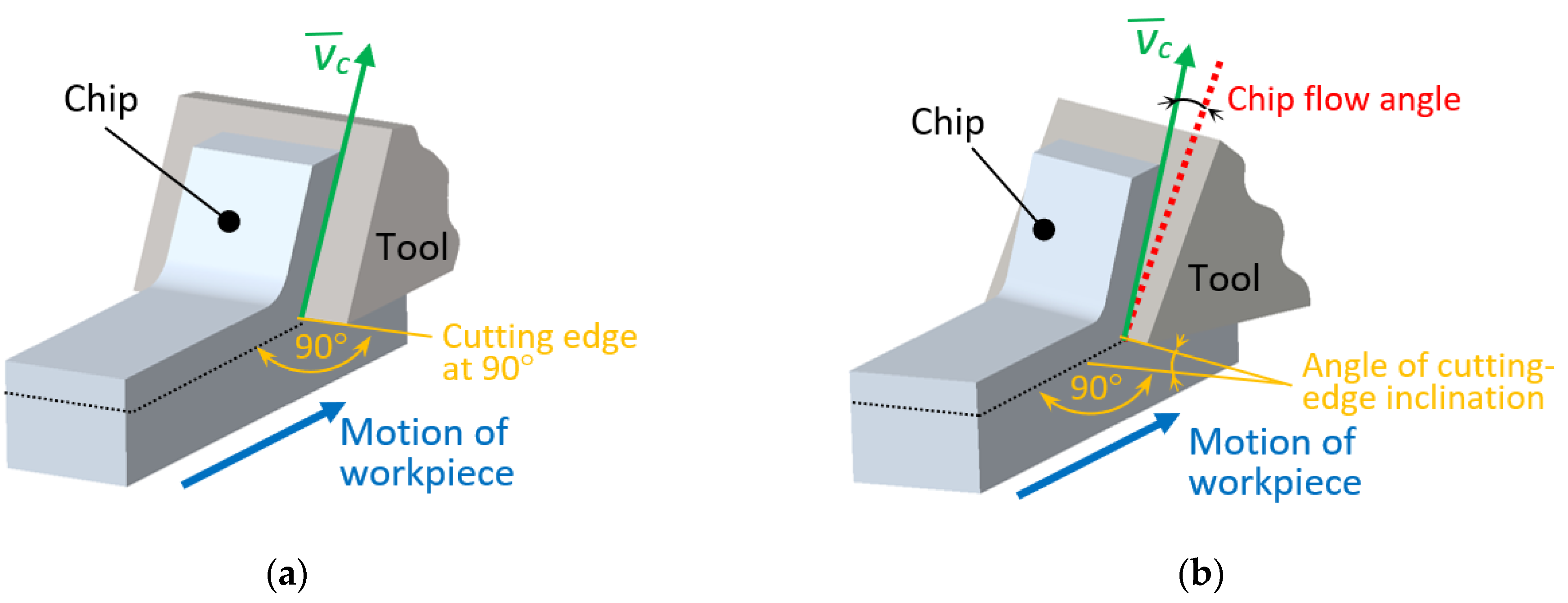
14]. At slow-rate machining, the chip-formation process can be observed in both cutting methods, orthogonal and oblique.
For orthogonal cutting (Figure 1a), it is characteristic that the cutting edge is perpendicular to the direction of movement of the tool and wider than the width of the cut. The shear force acts on a smaller area, so shear force per unit area is higher and the tool life is shorter than obtained in oblique cutting [15,16]. The forces that occur in this type of machining can be drawn in a plane, which is why it is also known as 2D machining [17]. If the angle between the cutting edge and the movement of the tool is not “right” (90°), it is an oblique cutting, which is also called 3D machining, because the cutting force is not planar, but spatial and is represented by 3 components [18]. All these facts affect the cutting conditions, tool life, durability as well as the quality of machined surface.
In both types of machining, the chip resulting from the interaction of the tool with the workpiece plays a crucial role in determining the properties of the machined surface and tool life. Properties that reflect its behaviour in the shear plane (acceleration of shear deformation, shear stress and shear angle) can also be represented by temperature and microhardness [19,20].
Jain et al. [21] verified the degree of influence of shear strain accelerations on the microhardness of chips during machining under the same cutting conditions. The basis of the hypothesis was the fact that the acceleration of shear deformation controls machining parameters such as tool-chip interface temperature, shear angle, tool wear, etc., and the hypothesis was confirmed.
The process of chip development in high-speed machining of hardened steel was studied by Wang et al. [22]. Research has confirmed that the formation of chips, when cutting materials of different hardness, can be controlled by setting a suitable combination of technological parameters. The hardness of the material as well as the local temperature increases with increasing cutting speed. When the parameters are in equilibrium, the deformation is concentrated in the shear zone and adiabatic shear occurs.
The effect of cutting conditions on the microhardness of the material in the cutting area along with chip thickness was investigated by Alrabii and Zumot [23] in experimental tests. They reported that microhardness increases with increasing cutting parameters (depth of cut, speed and feed), but only to a certain extent. Above this level, an increase in cutting parameters causes a decrease in microhardness.
The influence of changes in the microstructure of AISI 1045 steel on diffusion wear during turning in a zone of chip formation as a function of variable cutting speed was investigated Pu et al. [24]. The results of the research showed that with the cutting speed increasing, the grain size of the various phases also increases.
Response surface methodology was used in the study of Senussi [25] to specify the root cause of an effect of the relationship between chip microhardness and input control variables influencing the response as a 2D or 3D hypersurface. He stated that the combined effect of cutting speed at its lower level, feed rate and cutting depth at their higher values could result in increasing the microhardness of the chip.
Various approaches have been used by many researchers to study the effect of cutting parameters on chip properties and behaviour. The issues of microhardness, temperature, geometry and chip shape within analytical and numerical models have been developed in several studies [26,27,28,29,30], however, the complexity of the chip generation process forced the authors to simplify the simulation conditions, which, however, affected the accuracy of the obtained results, which did not correspond to the real state.
It can be said that many studies were focused on the influence of cutting parameters on microhardness and temperature evaluation in the past, but mostly the object of their investigation was the machined material or the cutting tool. However, only a few studies have addressed the microhardness and temperature of the chips generated during machining, but no study has compared the degree of influence of both the tool geometry (angle of tool-cutting-edge inclination and angle of the tool-orthogonal rake) and the technological conditions (depth of cut, cutting speed) on the chip characteristics (temperature and microhardness) in orthogonal and oblique slow-rate machining of 1.0503 (EN C45) steel that is included in the presented research. Based on the measured data, behavioural models were created for the temperature and Vickers microhardness of chips at individual combinations of the factors. The experiments were carried out on specially prepared workpieces designed for immediate stopping of machining.
On the basis of the above, it can be said that the novelty of the research lies not only in its complexity and the combination of included research factors (from the type of machining and machined material, through the geometry of the tool to the technological conditions), which according to the authors’ best knowledge have not yet been studied, but also in the newly proposed methodology for obtaining chips in an attempt to bring the observed chip samples as close as possible to the state in which they were created so that the texture of such a chip corresponds to the current cutting speed.

2. Materials and Methods

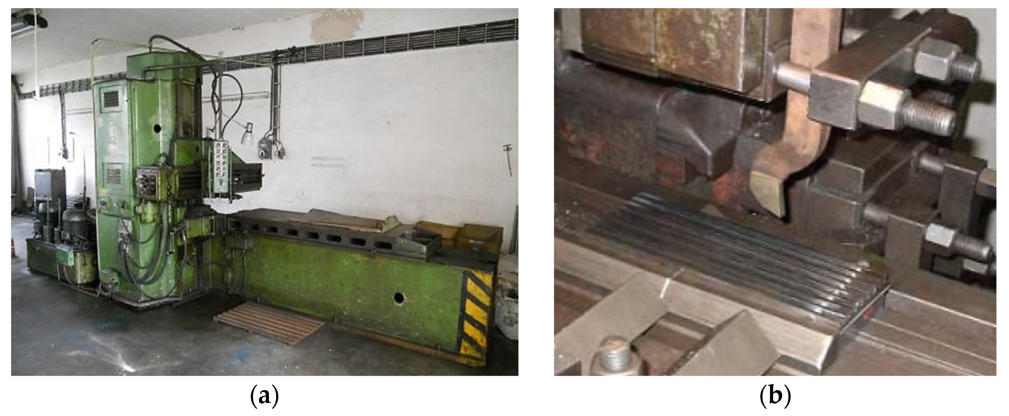
Planing technology, in which the workpiece performs the main movement, was selected for this study. In the experiments carried out as part of the presented research, a planing machine HJ8A type (KOVOSVIT inc., Holoubkov; Czech Republic) shown in Figure 2a was used. The process of planing of EN C45 steel is captured in Figure 2b. The machine is designed for the production of medium-heavy workpieces in piece and series production. The worktable has three levels of working and retraction speeds. The hydraulic drive is equipped with two gear pumps with separate electric motors, electromagnetic, hydraulic distribution and a combination of pump devices to change the speed levels of the table. The crossbar with support is vertically adjustable on the stand. The planer has two supports on the crossbar and one on the stands. Feeds and rapid feeds are controlled by the slide box at the end of the crossbar, either hydraulically or electrically. The table feed and the fast feeds of the crossbar, as well as the carriage, are controlled by the buttons from the hanging control box.
No cooling medium was used during machining, as the tool path was relatively short (about 200 mm), so there was no overheating of the tool and the material being processed.
Steel 1.0503 (EN C45), which is usually used in experiments as a standard [31], was chosen as the machined material within the experiments. It is a medium carbon-unalloyed structural steel that provides moderate tensile strength (in the range of 570–700 MPa), Brinell hardness of 170–210 and a good wear resistance. The material can be processed with hardening by means of quenching and tempering on focused and restricted areas. C45 can also be instigated with induction hardening up to the hardness level of HRC 55. This grade is in majority situations delivered in an unattended heat treatment state i.e., normalized condition, although it can be furnished also in numerous heat treatment variations. Machinability of C45 is equivalent to that of mild steel for example CR1 grade; on the other hand weld ability is exhibited lower than that of mild steel [32]. Steel is suitable for producing shafts of turbochargers, pumps, traction machines, electric motors, more giant gears, screws, automobile crankshafts, connecting rods, steering levers, spring hinges or pins. The chemical composition of machined 1.0503 (EN C45) steel is in Table 1.
The values of the cutting parameters (cutting speed vc, cutting depth ap) for experimental testing were chosen based on the requirements of technical practice, whereas the lowest cutting speed was given by the planer and corresponded to 60% of the machine’s power. Values for cutting depth ap were set based on machine limitations for maximum chip cross-section.
The planing necking tool type 32×20 ON 36550 HSS00 was used at orthogonal machining, whereas the straight roughing tool 32×20 ON 36500 HSS00 was employed at oblique machining. The brazed high-speed steel tips with three different values of the angle of cutting-edge inclination λs = 0°, 10° and 20° were applied within experimental testing [33].
The cutting tools used in the experiments are shown in Figure 3, and the next tools’ characteristics are given in Table 2.
The geometrical characteristics of the cutting tool were chosen in accordance with the machined material and the characteristics of the planing process. This method of machining requires the use of a more robust tool compared to turning. Increased robustness is required from the point of view of a significantly more dynamic way of first contact between the tool face and the workpiece [34]. The following requirements were also taken into account when choosing the tool geometry:
  • Compliance with the condition of the tool’s physical resistance to dynamic shocks when entering the cut;
  • The range of variable values ensuring the statistical significance of the experiment;
  • The difference in the characteristics of the chip formation process for orthogonal and oblique cutting.
According to the tool manufacturer’s recommendations, the rake angle when planing type C45 steels is chosen in the range of 8°–14°, and the angle of tool-orthogonal clearance αo for this type of steel is chosen in the range of 7°–11° [35].
Considering all the demands and recommendations, the angle of tool-orthogonal clearance αo, adopted the strategy of using the smallest value (7°) in terms of production recommendations and the other two values are in a linear series with an increment of 4° for the tools within the presented experiments.
Similarly, in the research, the angles of the tool-orthogonal rake γo were set up so they reflected the requirement to ensure the lowest possible specific resistance, whereas the maximum value was related to the bending stiffness of the cutting wedge. Specifically, for the planing necking tool, an interval of three values graduated by 4° from the smallest recommended value (8°) was chosen for the angle of the tool-orthogonal rake γo. For the straight roughing tool, the manufacturer’s recommended values of the angle of tool-orthogonal rake γo were reduced due to an effort to increase the strength properties of the tool tip and were used in gradations of 3°/7°/11°. For this tool, for the same reason of increasing the strength of the tip, the tool included angle εr in the value of 100° was used.
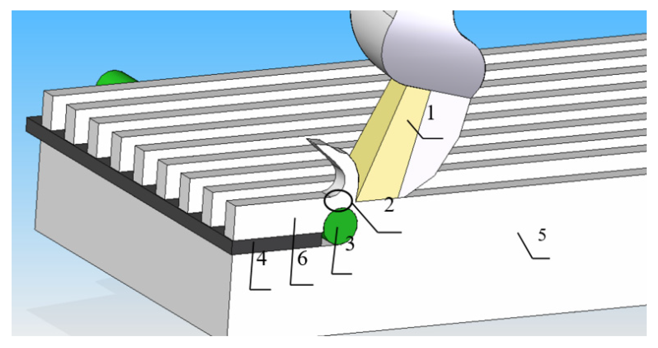
In order to observe changes in the chip formation zone, it was necessary to stop the machining process and break the contact of the tool with the workpiece. For this purpose, a methodology of immediate machining stop was developed based on the observation of chip behaviour during face milling, in which the end of the chip breaks off when leaving the cut. Observations have shown that the texture of such a chip corresponds to the actual speed at the moment of interruption of the cut. This know-how led the authors to use it in the presented research, and so they have developed a new methodology of obtaining chip roots based on the special modifications of the machined sample. The principle of the methodology is based on the designing of a specific workpiece (shown in Figure 4), and it is described below.
After milling the grooves of 10 mm × 10.5 mm into a semi-finished product with dimensions of 240 mm × 87.5 mm × 30 mm in the longitudinal direction, 11 protrusions with a rectangular cross-section of 10.5 mm × 2.5 mm were created, and each protrusion was used for a separate experiment.
At the end of the sample, where the tool comes out of the grip, the protrusions were undercut, and a plate was inserted into the resulting gap, which had the task of preventing the deformation of the final sample. The most crucial role in the cutting interruption process was played by a transverse hole with a diameter of 8 mm, which was drilled in front of the reinforcing plate (from the point of view of the cutting direction) and which was subsequently also reinforced with a metal rod. When the tool passed over the hole, the cross-section narrowed, and the material was torn, and the end part of the protrusion was thrown sharply in the direction of the tool’s movement at speed greater than the cutting speed. The separated end parts together with the resulting chip served as samples that captured the state of plastic deformation corresponding to the actual cutting speed.
An infrared thermometer UNI-T UT305C (Uni-trend Technology Co., Ltd., Dongguan City, Guangdong Province, China) was employed to measure the temperature of various surfaces by measuring the infrared radiation emitted from a focused surface and whose specifications were sufficient for the experiments carried out in this research. Its basic characteristics were: Temperature range −50~1550 °C; Accuracy ±1.8%; Repeatability ±0.5%; Resolution 0.1; Response time 250 ms (95% of reading); Emissivity 0.1~1.0 adjustable; Laser power <1 mW; Laser wavelength 630~670 nm; Spectral response 8~14 μm.
Since the temperature measurement was performed only on a cutting length of 200 mm, it was assumed that the increase in temperature in the cutting area was directly proportional to the increase in the size of the cutting path of the tool.
The obtained samples were cast in technical dentacryl, which has good insulating properties, high mechanical strength and perfect thermal insulation. The cast samples were ground using water, which had a cooling effect and thus prevented the sample from being affected by heat. In Figure 5a, the ground and polished sample are shown. After polishing, the samples were etched with Nital, which is a 2% solution of nitric acid HNO3 in ethyl alcohol. After being etched on the surface, a sample structure of the material was observed with the Platinum USB digital microscope UM019 (Shenzhen Handsome Technology Co., Ltd., Shenzhen, China) with a magnification of 25–220×. An example of an etched sample is shown in Figure 5b.
Microhardness was measured with a Micro–Vickers hardness tester CV–403DAT (Figure 6a) according to STN EN ISO 6507-1 standard. The measuring device involves a microscopic and a static method expressed on Vickers or Knoop scales, with magnifications of 200× and 600×. The microhardness measuring according to the Vickers method is determined by optical magnification by pressing a diamond regular quadrilateral needle with a peak wall angle of 136° into the tested material and then measuring the diagonals perpendicular to each other after relieving the load. The loading force acts in a perpendicular direction on the surface of the test specimen.
Hardness measurements were performed in the area of the shear angle at a load of 200 gf (gram-force) for a dwell of 10 s. An example of the tested sample with an imprint under 600× magnifications is shown in Figure 6b.

3. Results and Discussion

The experiments were carried out within the so-called “planned experiment” that was designed at three levels (lower, basic, and upper). The temperatures were measured in a cutting zone for orthogonal and oblique machining, and the micro-hardness of the material was measured in the area where the shear angle was formed. Measured data were evaluated through the statistical method using a regression function. Outliers from each group of measurements were specified using Grubbs test criteria and were excluded from further statistical processing of the results. Regression coefficients were calculated by means of Matlab software, and their significance was examined according to Student’s test criterion. The adequacy of the regression function was evaluated according to the Fisher-Snedecor test criterion F < F0.05 (f1, f2), where the degrees of freedom f1 = Nq (N is a number of measures, q is a number of significant coefficients) and f2 = N (m − 1), where m is a number of assessed measurements within the Grubbs’ test [36,37,38,39].
The variables listed in Table 3 were considered within the experimental study, and the codes for individual variables’ specific values are referred in Table 4.
Although the evaluation of tool wear was not the main goal of the research, it can be said that the dominant mechanism of tool wear during planing in the experiments was abrasive wear, which was manifested in the change of the geometry of the tool on the flank surface.

3.1. Temperature Evaluation

To evaluate the behaviour of the temperature and the influence of the monitored parameters on it, the regression dependencies for orthogonal machining of EN C45 steel were expressed by Equation (1), and for oblique machining by Equation (2), and the meaning of parameters x1 ÷ x4 is explained in Table 3 and Table 4 above. The calculated Fisher–Snedecor criterion [40] confirmed that the equations were functionally dependent and the coefficients of determination of the relations were R2 = 0.90 and 0.91, respectively:
y = 3.4146 5.7289 x 1 + 6.0652 x 2 + 6.6299 x 3 + 0.1732 x 4 0.3957 x 1 x 2 + 0.3796 x 1 x 3 + + 0.0634 x 1 x 4 0.3435 x 2 x 3 + 0.0202 x 2 x 4 + 0.0559 x 3 x 4 + 2.6854 x 1 2 + 5.0529 x 2   2 4.7508 x 3 2 + + 0.0934 x 4 2
y = 2.415 + 5.9456 x 1 3.438 x 2 + 0.5381 x 3 + 0.1701 x 4 0.0292 x 1 x 3 + 0.0163 x 1 x 4 + 0.2491 x 2 x 3 + 0.0355 x 2 x 4 0.0181 x 3 x 4 2.9253 x 1 2 3.0763 x 2 2 0.3104 x 3 2 + 0.0592 x 4 2
Using Equations (1) and (2), the temperature dependences on a combination of two parameters were plotted out of four monitored (depth of cut, cutting speed, face angle and inclination of the cutting edge of the tool) so that the behaviour of the temperature field could be evaluated.
When orthogonal cutting of carbon steel EN C45 in the interaction of cutting speed and cutting depth, the cutting depth had a more significant effect (Figure 7a). The cutting speed had a much milder effect, and the highest temperature values were achieved at the minimum cutting speed and the maximum values of the cutting depth. Conversely, in the oblique cutting of carbon steel (Figure 7b), the maximum temperatures were reached at the minimum cutting depth and the maximum cutting speed.
The influence of the angle of the tool-orthogonal rake and the cutting speed in orthogonal cutting is almost equally important/intense (Figure 8a), whereas in oblique cutting, the angle of orthogonal rake has an almost imperceptible effect compared to the impact of the cutting speed (Figure 8b). In both cases, the maximum temperature values were reached at the mean values of the angle of the tool-orthogonal rake, but as already mentioned, the temperature reacts in the opposite way to a change in cutting speed. The maximum temperature in orthogonal cutting is at the minimum cutting speed, and in oblique cutting, it is at the maximum cutting speed.
The influence of the angle of tool-cutting-edge inclination λs is almost undetectable; the more significant impact on temperature has the cutting speed (Figure 9).
The influence of the angle of the tool-orthogonal rake on the temperature is more evident in the orthogonal cutting of carbon steel (Figure 10a) than in oblique cutting (Figure 10b), and the maximum temperature values are reached at their mean values. The cutting depth has a more pronounced effect, and it is precisely in the opposite way. At orthogonal cutting, the maximum temperature values are reached at the maximum cutting depth values, and at oblique cutting, the maximum temperature is reached at the minimum cutting depth. In both types of cutting, the angle of tool-cutting-edge inclination λs has no noticeable effect on the change in cutting temperature compared to the cutting depth (Figure 11).
The angle of tool-cutting-edge inclination at the orthogonal cutting of carbon steel (Figure 12a) has an almost unnoticeable effect compared to the angle of the tool-orthogonal rake. However, it is different at oblique cutting (Figure 12b), where maximum temperature values are reached at the maximum angle of tool-cutting-edge inclination. The angle of the tool-orthogonal rake had a more prominent effect in orthogonal cutting, but the maximum temperature was reached at its mean values in both cutting methods.
On the basis of experiments aimed at determining the influence of the investigated factors on the temperature of the chip, it is possible to evaluate achieved results from three points of view:
  • From the point of view of the cutting speed, the results of the research are characterized for orthogonal cutting by a slight decrease in the temperature of the chip as the cutting speed increases. From the point of view of theoretical and practical knowledge, such a trend occurs at very high cutting speeds, when the chip removal speed from the cutting site is significantly higher than the heat conduction speed in the machined material, which is used in high-speed machining. In oblique cutting, the maximum temperature of the chip is reached in roughly 2/3 of the range of cutting speeds, which decreases slightly with the further increase in the cutting speed values. However, according to theoretical knowledge, the trend should be rising. The deviation between the research results and the theoretical starting point is probably caused by the influence of the complexity of the experimental system, as well as the factors of the experimental conditions that are uncontrollable.
  • From the point of view of the change in cutting depth, significantly opposite tendencies for orthogonal and oblique cutting occurred. With this phenomenon, it should be noted that the temperature gradient in the graphical interpretation of the results is about 45 °C for orthogonal cutting and about 15 °C for oblique cutting. The influence of the cutting depth on the cutting temperature in orthogonal cutting represents the current theoretical and practical knowledge very well—with increasing depth of cut, the degree of deformation of the machined material increases, which outwardly manifests as an increase in temperature in a geometric trend. In oblique cutting, this experiment showed a trend of a slight increase in chip temperature while reducing its thickness. This phenomenon is in contrast to the simplified theoretical model of cutting. This opposite trend in the behavior of the acquired dependence can be explained by the interaction of two factors causing a slight decrease in chip temperature when increasing its thickness (influence i).
  • From the perspective of the angle of the tool-orthogonal rake γo, the research results indicate for orthogonal cutting that the maximum chip temperature is reached in roughly half of the range of angles examined. This trend is most likely caused by the interaction of influences of both used methodologies of experimental measurement and data evaluation. In oblique cutting, the effect of the dependence of chip temperature on the angle of the tool-orthogonal rake γo is insignificant, which is in accordance with current knowledge.
  • The influence of the angle of tool-cutting-edge inclination λs on chip temperature is almost undetectable in accordance with theoretical knowledge.
The influence of parameters on the maximum measured temperature during orthogonal and oblique EN C45 machining is clearly shown in Table 5.

3.2. Vickers Microhardness Evaluation

Similar to the measured temperature results, as well as for the obtained HV microhardness values, regression analysis was used to determine the dependencies on the investigated parameters, which are expressed by Equations (3) and (4), for orthogonal and oblique cutting, respectively. The reliability of the relations is R2 = 0.87 and 0.90, respectively. Plotted dependencies of microhardness on different combinations of two parameters are shown in Figure 13, Figure 14, Figure 15, Figure 16, Figure 17 and Figure 18.
y = 0.0771 + 4.5677 x 1 0.484 x 2 0.2907 x 3 0.1027 x 4 + 1.2326 x 1 x 2 + 0.0893 x 1 x 3 + 0.0603 x 1 x 4 0.0892 x 2 x 4 + 0.0476 x 3 x 4 1.8966 x 1 2 + 0.8444 x 2 2 + 0.1503 x 3 2 + 0.0208 x 4 2
y = 5.9254 2.2198 x 1 + 12.092 x 2 + 3.0554 x 3 0.2568 x 4 + 0.9296 x 1 x 2 0.0616 x 1 x 3 0.0356 x 1 x 4 0.6367 x 2 x 3 + 0.0233 x 3 x 4 + 1.4725 x 1 2 + 11.3708 x 2 2 2.1329 x 3 2 0.096 x 4 2
The microhardness in orthogonal machining (Figure 13a) is much more influenced by the cutting speed than the cutting depth. In oblique cutting, it is precisely the opposite (Figure 13b), and the cutting depth has a much more pronounced effect, and the greatest micro-hardness is achieved at its maximum values.
The dependencies on Figure 14 show that the angle of the tool-orthogonal rake during orthogonal cutting (Figure 14a) affects the microhardness only imperceptibly compared to the effect of the cutting speed, whereas during oblique cutting (Figure 14b) the intensity due to the influence of the angle of the tool-orthogonal rake and the cutting speed is almost the same. In orthogonal machining, the maximum values of microhardness were achieved at the maximum values of the cutting speed and marginal values of the angle of the tool-orthogonal rake. During oblique cutting, the maximum microhardness was achieved at the minimum cutting speed and medium values of the angle of the tool-orthogonal rake.
The angle of inclination of the main cutting edge in both carbon steel cutting methods (Figure 15) does not significantly affect the change in microhardness HV compared to the cutting speed.
The effect of the thickness of the cut layer in interaction with the face angle on the change of microhardness appears to be the same in orthogonal (Figure 16a) and in oblique cutting (Figure 16b). In this case, the influence of the face angle is interesting, where in orthogonal cutting the microhardness maxima are reached at its extreme values, in oblique cutting at its mean values.
The influence of the angle of inclination of the main cutting edge (Figure 17) is not noticeable in both cutting methods due to the influence of the thickness of the cut layer, which is very significant.
In the interaction of the tool-orthogonal rake angle and the angle of inclination of the main cutting edge (Figure 18), the angle of inclination has a non-significant effect on the microhardness change HV in both machining methods when compared to the effect of the angle of the tool-orthogonal rake.
The results of research aimed at determining the dependence of chip microhardness on selected factors of the cutting process pointed out that:
  • The growing depth of the cut causes an increase in the rate of deformation in the primary deformation zone, which leads to an increase in strengthening and therefore of hardness. The increased rate of deformation, however, also tends to generate a significantly greater amount of heat, which reduces the manifestations of strengthening and thus microhardness. The experimentally obtained results are in accordance with theoretical knowledge for both orthogonal cutting and oblique cutting.
  • From the point of view of the cutting speed, the values of the theoretical microhardness are achieved by a combination of two basic opposing phenomena—an increasing cutting speed participates in a higher strengthening of the removed material, but at the same time generates a greater amount of heat, which reduces the strengthening. Then, the mutual combination of these two opposing events with material and process properties participates in the final trend of microhardness dependence. For orthogonal cutting, the dependence shows a maximum in about 2/3 of the cutting speed range with a gradient of roughly 200 HV. In oblique cutting, the minimum microhardness of the chip with a gradient of approx. 125 HV is achieved in approximately 1/2 of the range of cutting speeds.
  • From the perspective of the angle of the tool-orthogonal rake γo, the research results point to insignificant changes in microhardness with respect to this angle for orthogonal cutting. For oblique cutting, the trend of microhardness dependence on this angle shows a maximum in roughly half of the range of investigated values with a gradient of approximately 150 HV.
  • The influence of the angle of tool-cutting-edge inclination λs on HV microhardness is almost undetectable in accordance with theoretical knowledge.
The overview of the influence of selected parameters on Vickers microhardness in the area of occurrence of the shear angle on samples made of carbon steel EN C45 is shown in Table 6.

4. Conclusions

Planing is one of the slow-speed machining types, and although it is a technology that is rarely used today, its effectiveness for specific types of workpieces can be much higher than that of milling. However, the phenomena taking place at slow-speed machining are similar to, for example, broaching, but in this case the chip remains between the teeth of the broaching mandrel and inside the workpiece, and therefore the process of chip formation cannot be observed or investigated (or only under very complicated conditions).
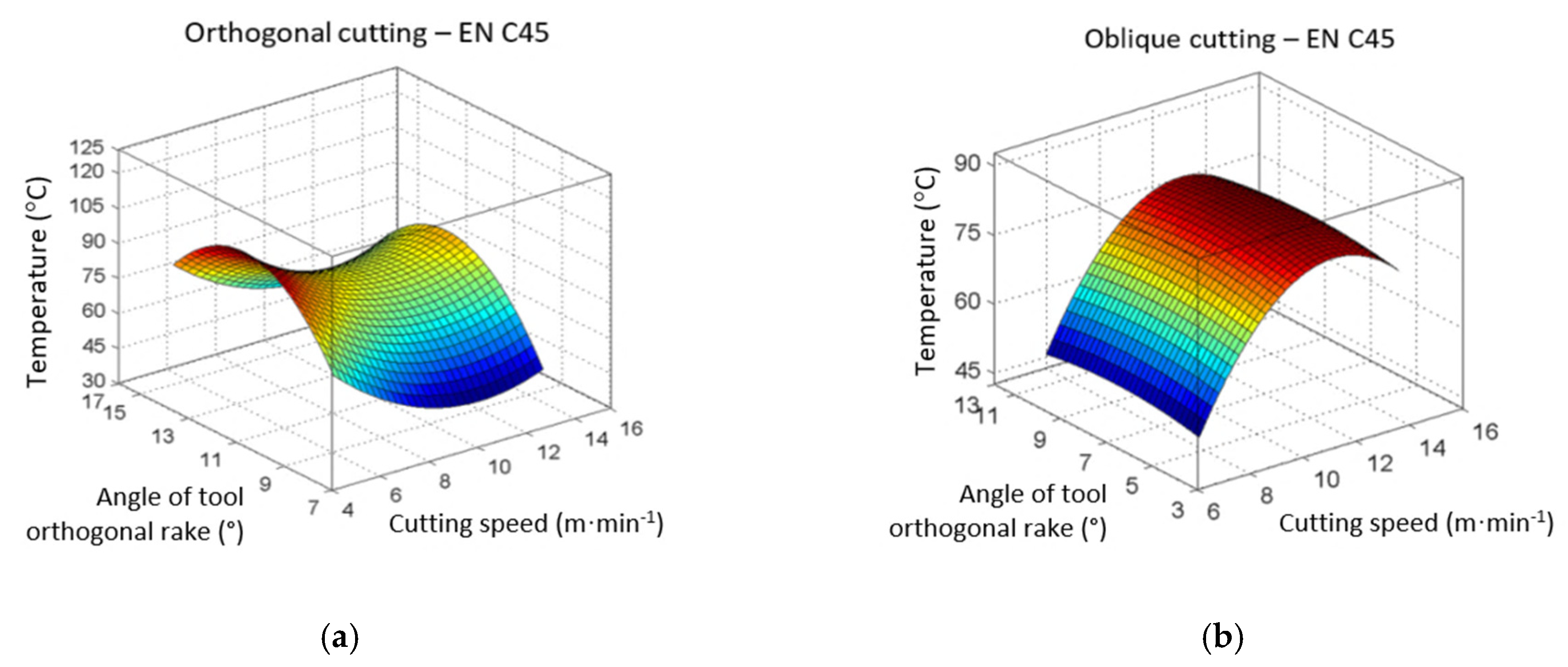
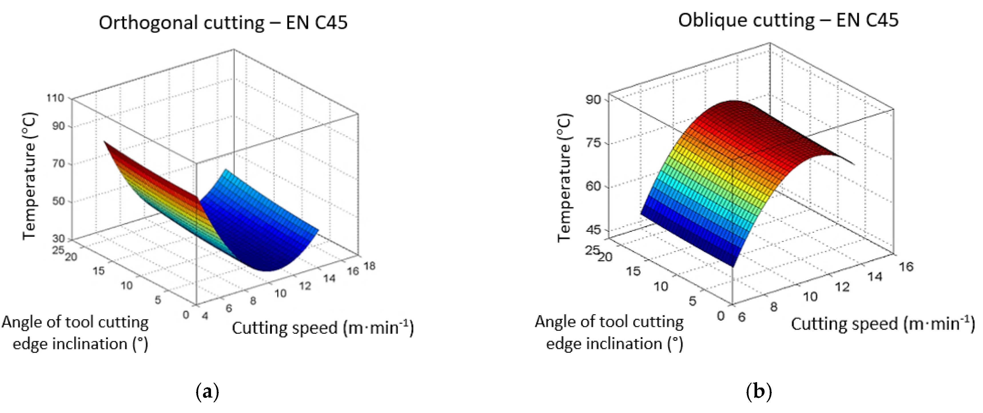
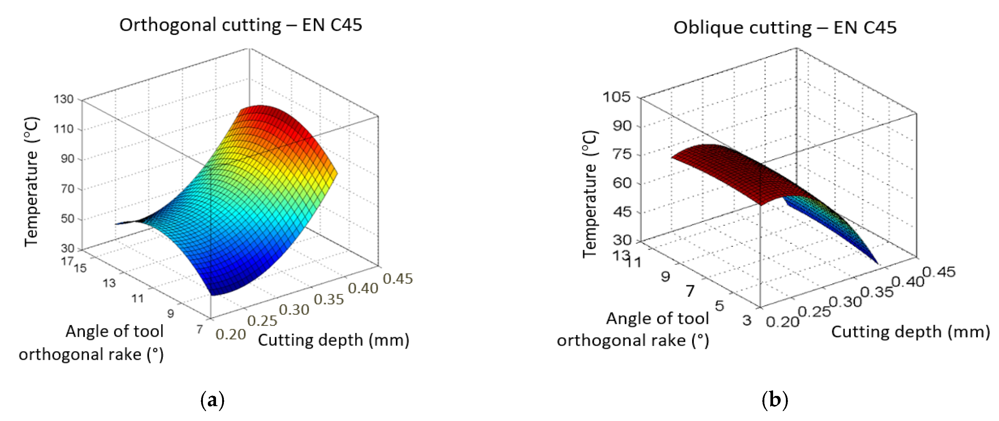
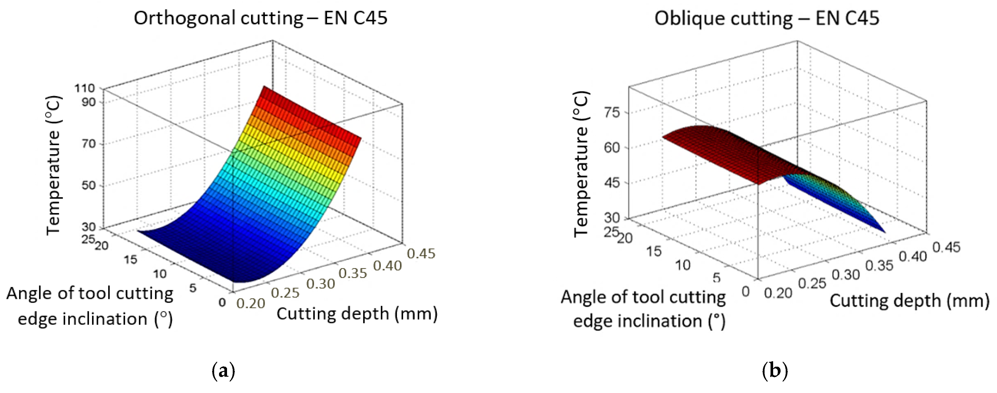
The presented research aimed to analyse the influence of selected parameters on the temperature during cutting operations performed at relatively low cutting speeds and to compare the results at orthogonal and oblique machining. The new methodology for obtaining the chip root was designed so that the chip samples correspond as much as possible to the conditions of the ongoing event and to the current speed at the given moment of machining,
The experiment was designed by the orthogonal experimental composition plan of the investigation through the “star points”. The effect of four parameters (cutting speed vc, the angle of inclination of the main cutting edge λs, the depth of cut ap and the angle of the tool-orthogonal rake γ) on temperature T (°) and Vickers microhardness HV was investigated in the area where the shear angle was formed.
Carbon steel EN C45, which is usually used in the experiments as a standard, was tested in two types of cutting, i.e., orthogonal cutting with a planing necking tool and oblique cutting with a straight roughing tool without cooling. Based on the measured values, the statistical regression dependencies were compiled, where various test criteria were used to verify the measured results, e.g., Grubbs criterion for detecting outlying measured results or gross errors, Cochran’s criterion for homogeneity of variance, Student’s test criterion for determining the significance of regression coefficients, Fisher-Snedecor test criterion for confirming the adequacy of the statistical model. Subsequently, graphical dependencies were constructed and evaluated.
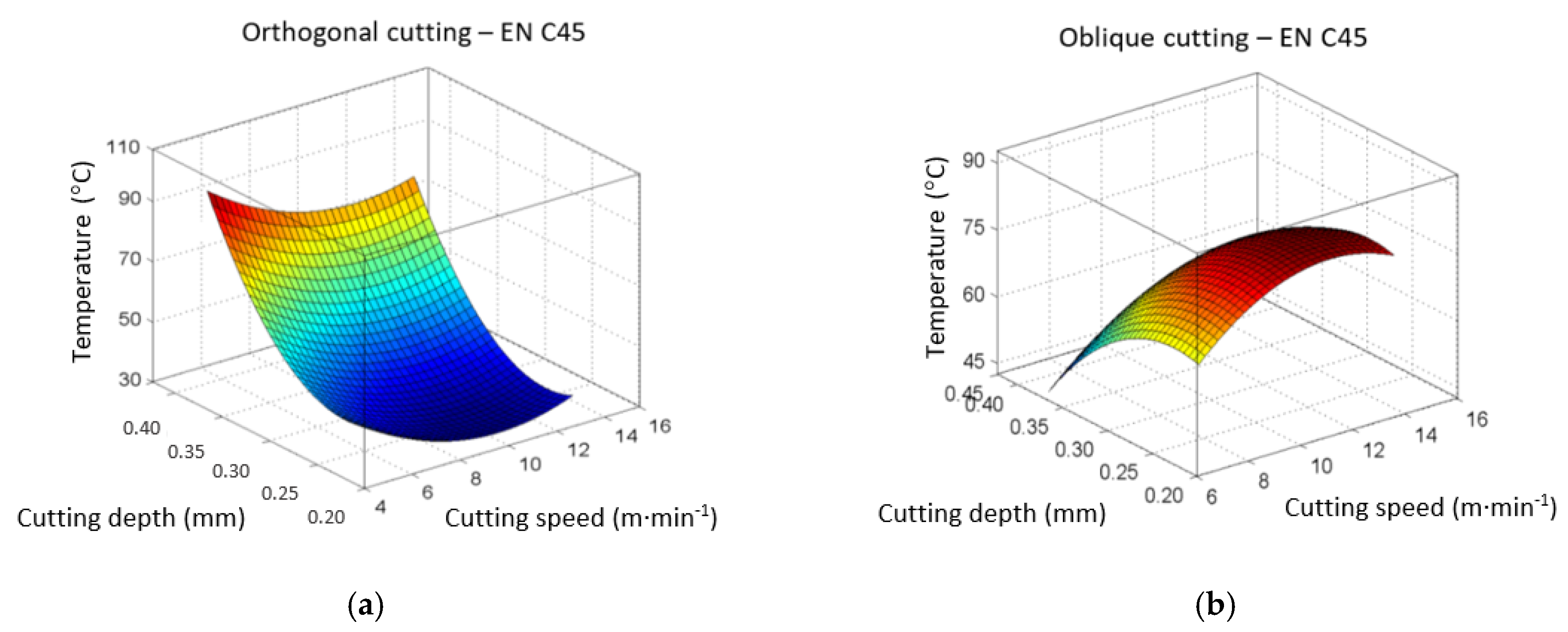
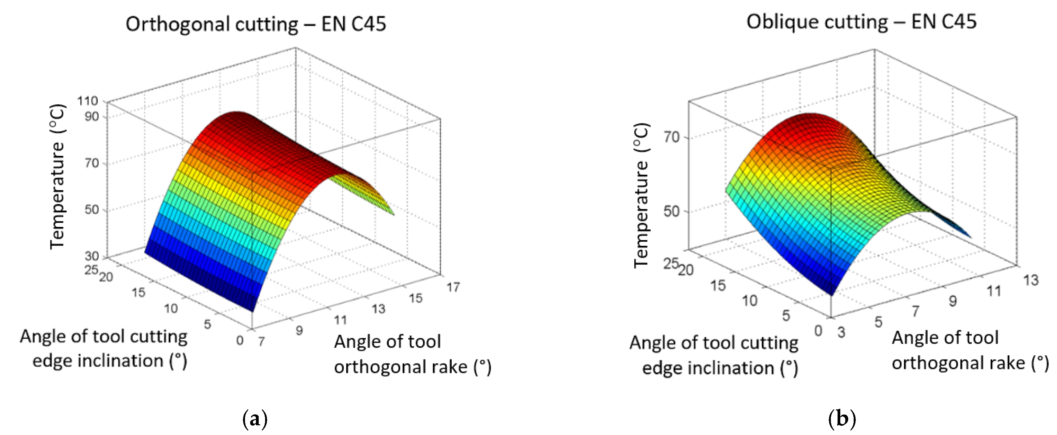
Based on the dependencies of the temperature on the selected parameters on samples made of carbon steel EN C45 in the area of occurrence of the shear angle, it can be concluded:
  • The most significant influence has the cutting depth in both orthogonal and oblique cutting, followed by the cutting speed, and the angle of the tool-orthogonal rake.
  • The observations have shown that the influence of the angle of inclination of the main cutting edge is inconspicuous (or almost non-existent).
  • The maximum temperature was reached at the maximum cutting depth at orthogonal cutting, in contrast to oblique cutting, in which the maximum temperature was measured at the minimum cutting depth. In both cases of cutting at the maximum temperature, the mean values of the angle of the tool-orthogonal rake played a role.
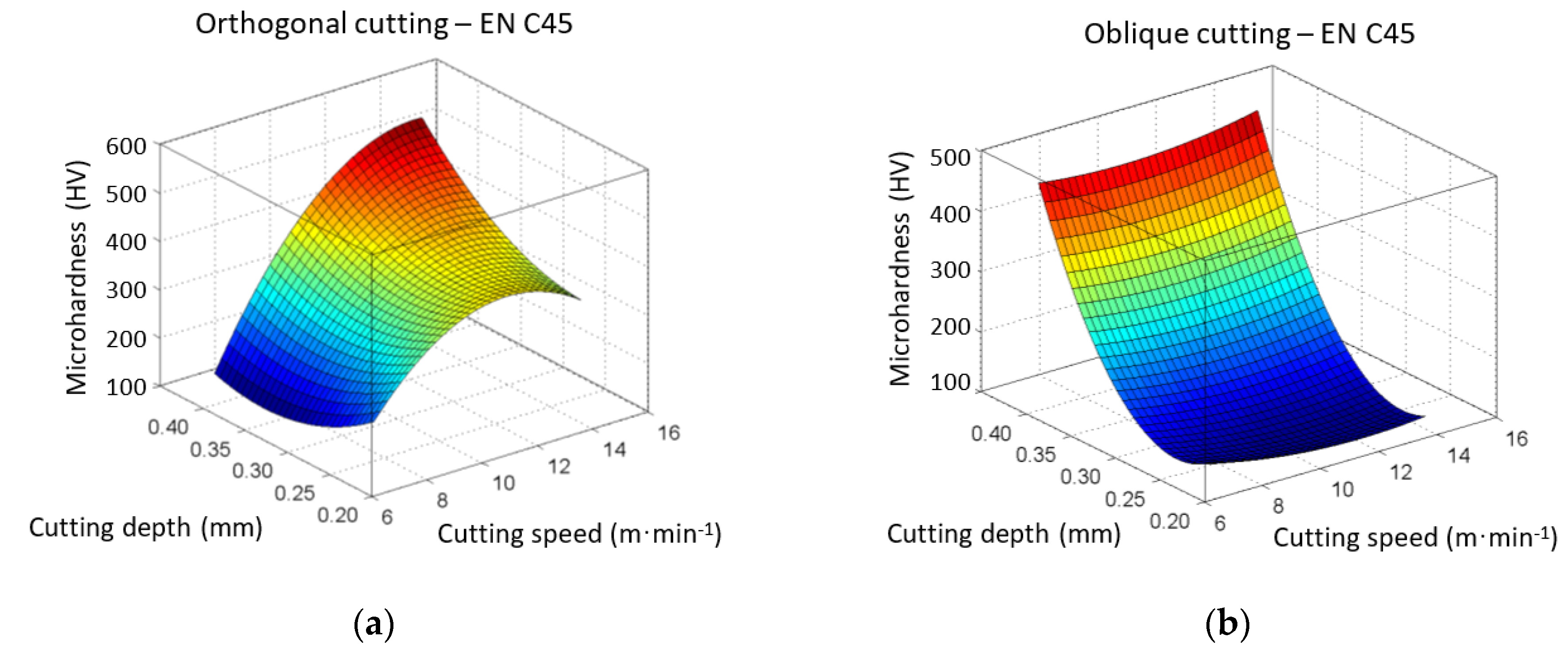
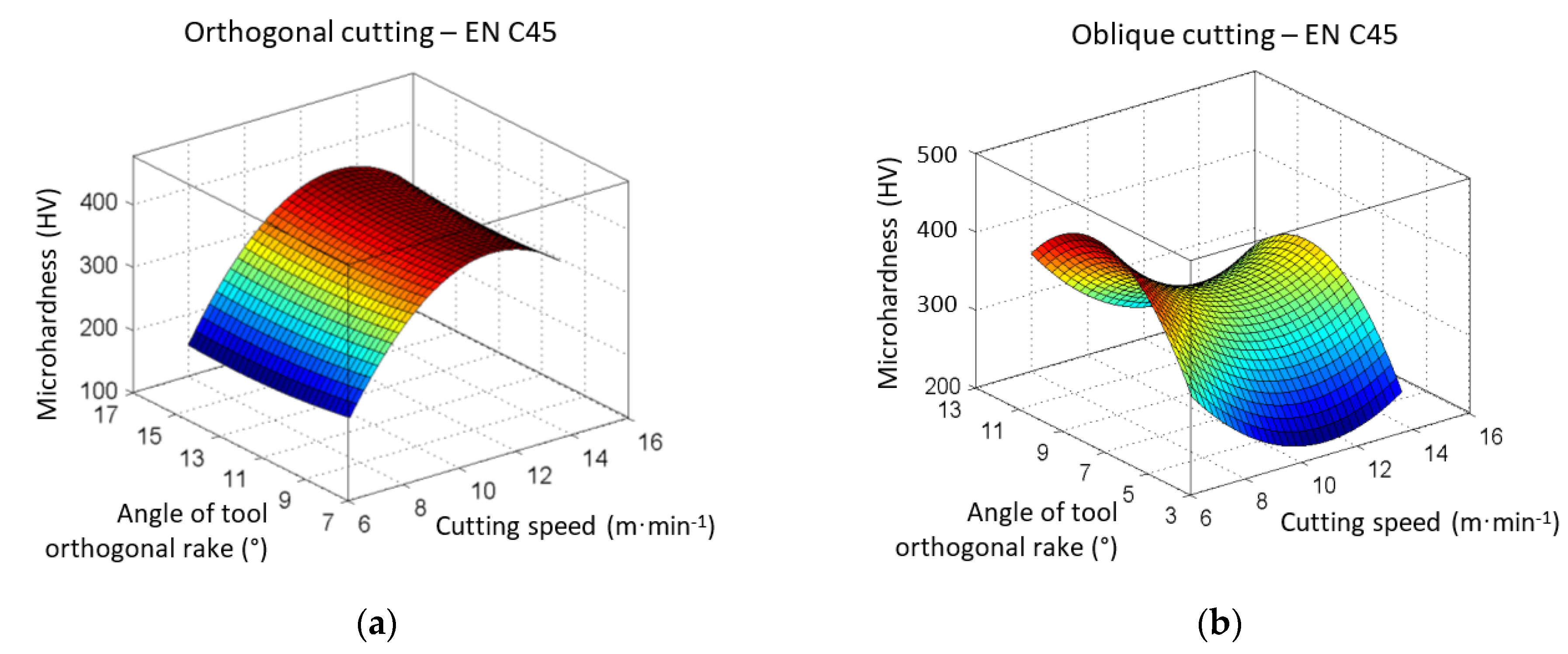
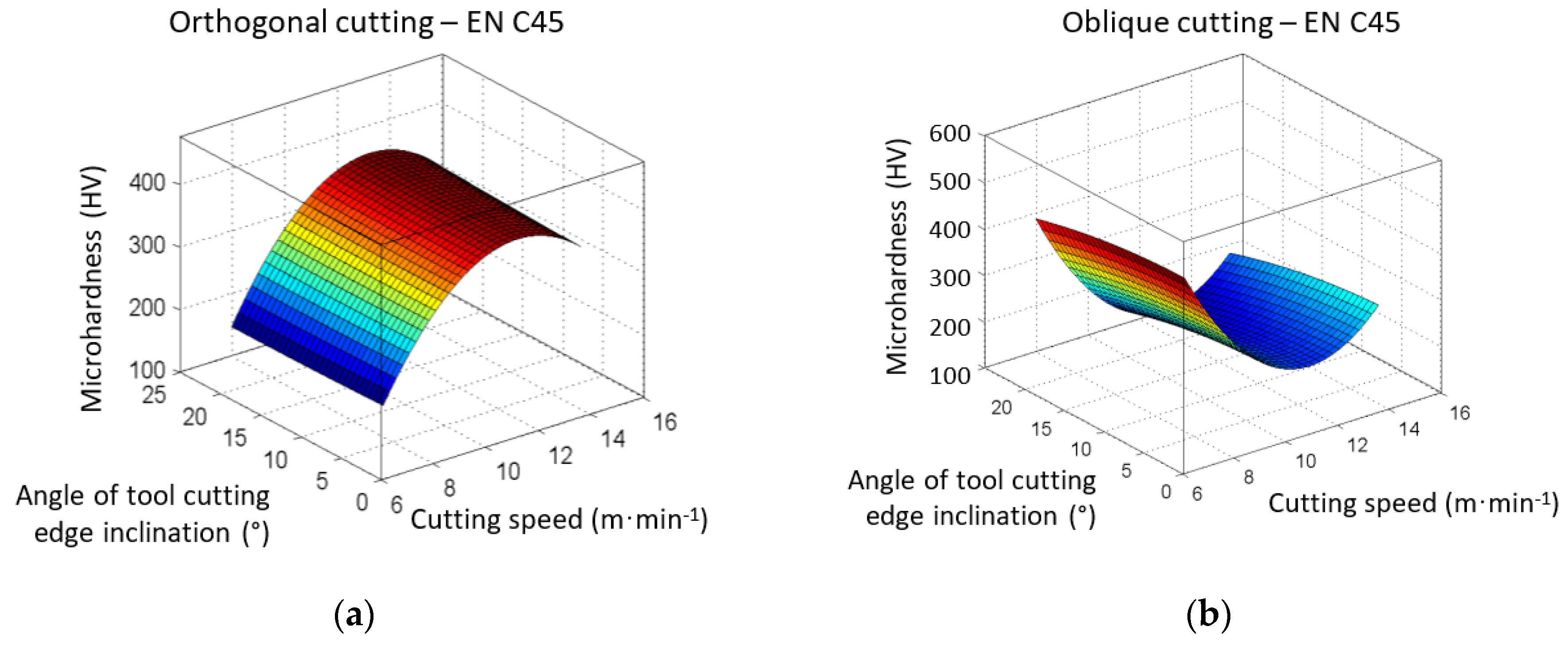
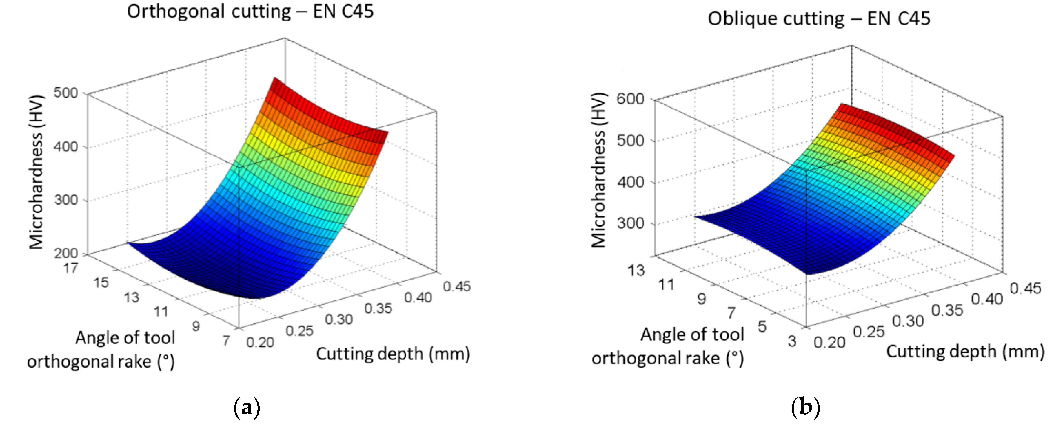
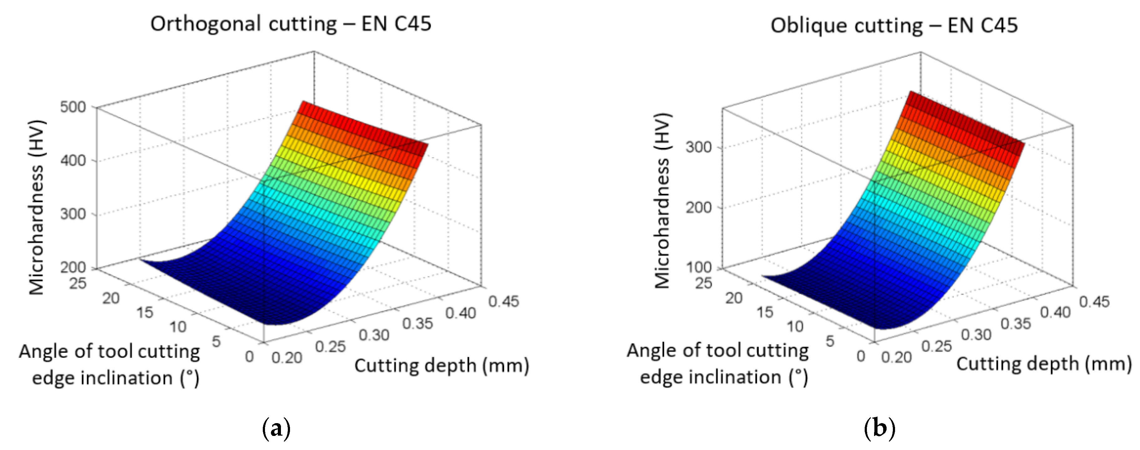
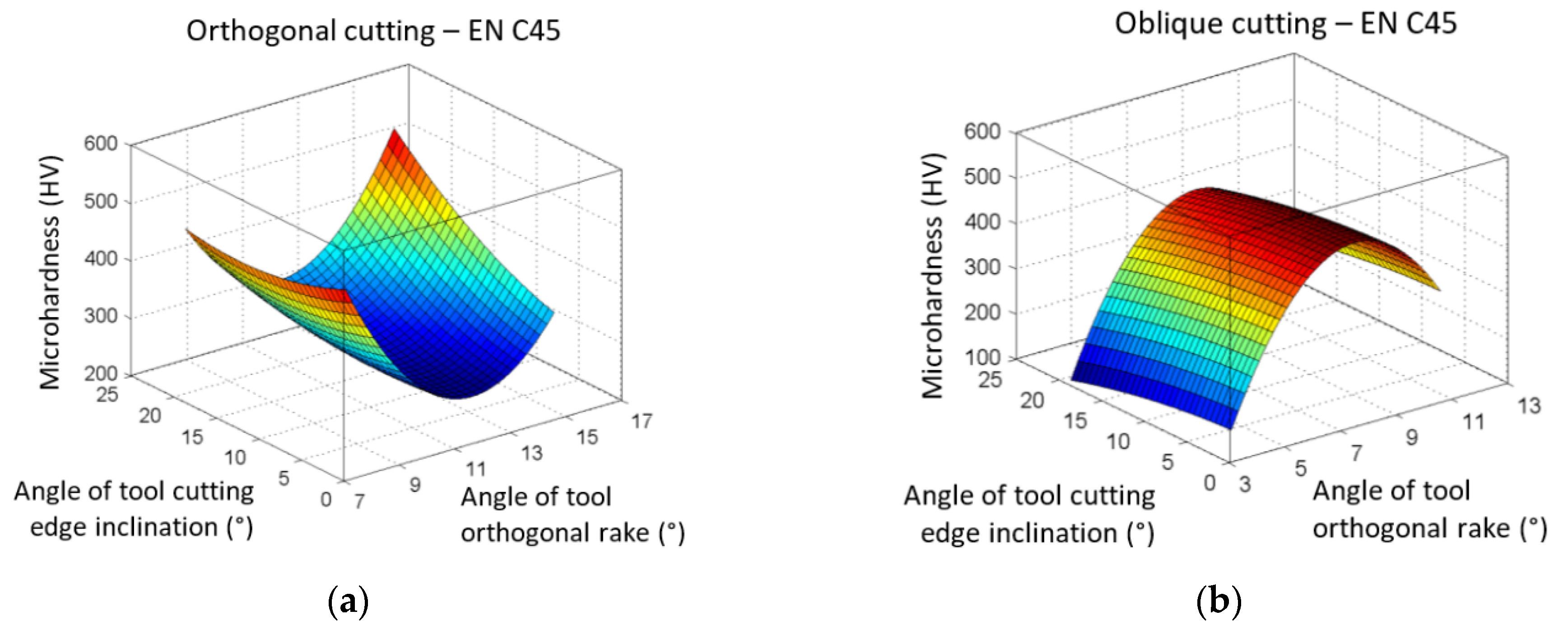
When evaluating the influence of selected parameters on Vickers microhardness, it can be stated:
  • The significance of the parameters for the change of the shear angle was manifested differently. In orthogonal cutting, the highest microhardness was measured at the highest cutting speed. In this case, the highest values of the cutting depth and the angle of cutting-edge inclination were also acquired.
  • During oblique cutting, the most significant influence on the change of microhardness HV had the cutting depth.
Information on the temperature development in the chip and microhardness values achieved under certain conditions indicate the suitability (or unsuitability) of choosing the selected combination of technological parameters, and together with the geometry of the tool, it is possible to subsequently increase/regulate the quality of the machined surface and the service life of the tool.
Although in the presented experimental research, the effort was to capture as much as possible the real state of the chip at the moment of separation from the machined surface and to prepare samples not only for measuring microhardness, but in the future also for observing microstructure changes, the authors realize that the machining process is so complex that obtaining samples that would perfectly reflect the state of chip formation at a given moment is almost impossible.

Author Contributions

Conceptualization, P.P.M. and A.S.; methodology, P.P.M. and K.M.; software, P.P.M. and M.K. (Martin Korol); validation, M.V. and M.K. (Milena Kubisova); investigation, P.P.M. and K.M.; resources, M.K. (Martin Korol) and K.M.; data curation, P.P.M. and M.K. (Milena Kubisova); writing—original draft preparation, K.M.; writing—review and editing, K.M.; visualization, M.V. and K.M.; supervision, P.P.M.; project administration, K.M.; funding acquisition, K.M. and P.P.M. All authors have read and agreed to the published version of the manuscript.

Funding

This research was funded by the grants APVV-19-0550, SK-CN-21-0046, KEGA 005TUKE-4/2021 and KEGA 032TUKE-4/2022.

Institutional Review Board Statement

Not applicable.

Informed Consent Statement

Not applicable.

Data Availability Statement

Not applicable.

Acknowledgments

The article was prepared thanks to support of the Ministry of Education of the Slovak Republic through the grants APVV-19-0550, SK-CN-21-0046, KEGA 005TUKE-4/2021 and KEGA 032TUKE-4/2022.

Conflicts of Interest

The authors declare no conflict of interest.

References

  1. Varga, G.; Sovilj, B.; Jakubowicz, M.; Babič, M. Experimental Examination of Surface Roughness in Low-Environmental-Load Machining of External Cylindrical Workpieces. In Advances in Manufacturing II; Lecture Notes in Mechanical Engineering; Springer: Cham, Switzerland, 2019; Volume 2, pp. 307–321. [Google Scholar] [CrossRef]
  2. Prasetyo, L.; Tauviqirrahman, M. Study of chip formation feedrates of various steels in low-speed milling process. IOP Conf. Ser. Mater. Sci. Eng. 2017, 202, 012097. [Google Scholar] [CrossRef]
  3. Pastucha, P.; Majstorovic, V.; Kucera, M.; Beno, P.; Krile, S. Study of Cutting Tool Durability at a Short-Term Discontinuous Turning Test. In Advances in Manufacturing Engineering and Materials; Lecture Notes in Mechanical Engineering; Springer: Cham, Switzerland, 2019; pp. 493–501. [Google Scholar] [CrossRef]
  4. Karkalos, N.E.; Markopoulos, A.P.; Manolakos, D.E. Cutting Speed in Nano-Cutting as MD Modelling Parameter. Int. J. Manuf. Mater. Mech. Eng. 2016, 6, 1–13. [Google Scholar] [CrossRef]
  5. Toulfatzis, A.I.; Pantazopoulos, G.A.; Besseris, G.J.; Paipetis, A.S. Machinability evaluation and screening of leaded and lead-free brasses using a non-linear robust multifactorial profiler. Int. J. Adv. Manuf. Technol. 2016, 86, 3241–3254. [Google Scholar] [CrossRef]
  6. Neslušan, M.; Mrkvica, I.; Čep, R.; Kozak, D.; Konderla, R. Deformations after heat treatment and their influence on cutting process. Teh. Vjesn. 2011, 18, 601–608. [Google Scholar]
  7. Tomczewski, L. The application of planing tools during turning. Adv. Sci. Technol. Res. J. 2015, 9, 83–86. [Google Scholar] [CrossRef]
  8. Chukarin, A.; Meskhi, B.; Shoniya, D. Theoretical analysis on regularities of the process of noise generation of planing, slotting and planing-milling machines. Akustika 2021, 41, 173–177. [Google Scholar] [CrossRef]
  9. Zetek, M.; Zetkova, I. Increasing of the Cutting Tool Efficiency from Tool Steel by Using Fluidization Method. Procedia Eng. 2015, 100, 912–917. [Google Scholar] [CrossRef]
  10. Kundrák, J.; Markopoulos, A.P.; Karkalos, N.E.; Makkai, T. The Examination of Cutting Force as Function of Depth of Cut in Cases with Constant and Changing Chip Cross Section. In Advances in Manufacturing II, Volume 4—Mechanical Engineering; Springer: Cham, Switzerland, 2019; pp. 405–415. [Google Scholar]
  11. Saglam, H.; Yaldiz, S.; Unsacar, F. The effect of tool geometry and cutting speed on main cutting force and tool tip temperature. Mater. Des. 2007, 28, 101–111. [Google Scholar] [CrossRef]
  12. Jurko, J.; Panda, A.; Behun, M. Prediction of a new form of the cutting tool according to achieve the desired surface quality. Appl. Mech. Mater. 2013, 268–270, 473–476. [Google Scholar] [CrossRef]
  13. Filippov, V.; Filippova, E.O. Determination of Cutting Forces in Oblique Cutting. Appl. Mech. Mater. 2015, 756, 659–664. [Google Scholar] [CrossRef]
  14. Bagci, E. 3-D numerical analysis of orthogonal cutting process via mesh-free method. Int. J. Phys. Sci. 2011, 6, 1267–1282. [Google Scholar]
  15. Filice, L.; Micari, F.; Rizzuti, S.; Umbrello, D. A critical analysis on the friction modeling in orthogonal machining. Int. J. Mach. Tools Manuf. 2007, 47, 709–714. [Google Scholar] [CrossRef]
  16. Aydin, M.; Koklu, U. A study of ball-end milling forces by finite element model with Lagrangian boundary of orthogonal cutting operation. J. Fac. Eng. Archit. Gazi Univ. 2018, 33, 507–516. [Google Scholar]
  17. Seah, K.H.W.; Rahman, M.; Li, X.P.; Zhang, X.D. A three-dimensional model of chip flow, chip curl and chip breaking for oblique cutting. Int. J. Mach. Tools Manuf. 1996, 36, 1385–1400. [Google Scholar] [CrossRef]
  18. Saglam, H.; Unsacar, F.; Yaldiz, S. Investigation of the effect of rake angle and approaching angle on main cut-ting force and tool tip temperature. Int. J. Mach. Tools Manuf. 2006, 46, 132–141. [Google Scholar] [CrossRef]
  19. Dewangan, S.; Chattopadhyaya, S.; Hloch, S. Wear Assessment of Conical Pick used in Coal Cutting Operation. Rock Mech. Rock Eng. 2015, 48, 2129–2139. [Google Scholar] [CrossRef]
  20. Vukelic, G.; Vizentin, G.; Ivosevic, S.; Bozic, Z. Analysis of prolonged marine exposure on properties of AH36 steel. Eng. Fail. Anal. 2022, 135, 106132. [Google Scholar] [CrossRef]
  21. Jain, V.K.; Kumar, S.; Lal, G.K. Effects of Machining Parameters on the Microhardness of Chips. J. Eng. Ind. 1989, 111, 220. [Google Scholar] [CrossRef]
  22. Wang, C.; Xie, Y.; Zheng, L.; Qin, Z.; Tang, D.; Song, Y. Research on the Chip Formation Mechanism during the high-speed milling of hardened steel. Int. J. Mach. Tools Manuf. 2014, 79, 31–48. [Google Scholar] [CrossRef]
  23. Alrabii, S.A.; Zumot, L.Y. Chip Thickness and Microhardness Prediction Models during Turning of Medium Carbon Steel. J. Appl. Math. 2007, 2017, 051905. [Google Scholar] [CrossRef]
  24. Pu, C.L.; Zhu, G.; Yang, S.B.; Yue, E.B.; Subramanian, S.V. Effect of Dynamic Recrystallization at Tool-Chip Interface on Accelerating Tool Wear During High-Speed Cutting of AISI1045 Steel. Int. J. Mach. Tools Manuf. 2016, 100, 72–80. [Google Scholar] [CrossRef]
  25. Senussi, G.H. Interaction Effect of Feed Rate and Cutting Speed in CNC-Turning on Chip Micro-Hardness of 304-Austenitic Stainless Steel. World Acad. Sci. Eng. Technol. 2007, 28, 121–126. [Google Scholar]
  26. Mabrouki, T.; Courbon, C.; Zhang, Y.; Rech, J.; Nélias, D.; Asad, M.; Hamdi, H.; Belhadi, S.; Salvatore, F. Some insights on the modelling of chip formation and its morphology during metal cutting operations. C. R. Mécanique 2016, 344, 335–350. [Google Scholar] [CrossRef]
  27. Umer, U.; Qudeiri, J.A.; Ashfaq, M.; Al-Ahmari, A. Chip morphology predictions while machining hardened tool steel using finite element and smoothed particles hydrodynamics methods. J. Zhejiang Univ. Sci. A 2016, 17, 873–885. [Google Scholar] [CrossRef]
  28. Adekunle, A.S.; Adedayo, S.M.; Ohijeagbon, I.O.; Olusegun, H.D. Chip morphology and behaviour of tool temperature during turning of AISI 301 using different biodegradable oils. J. Prod. Eng. 2015, 18, 18–22. [Google Scholar]
  29. Bai, W.; Sun, R.; Roy, A.; Silberschmidt, V.V. Improved analytical prediction of chip formation in orthogo-nal cutting of titanium alloy Ti6Al4V. Int. J. Mech. Sci. 2017, 133, 357–367. [Google Scholar] [CrossRef]
  30. Karmiris-Obratański, P.; Papazoglou, E.L.; Leszczyńska-Madej, B.; Karkalos, N.E.; Markopoulos, A.P. An Optimalization Study on the Surface Texture and Machining Parameters of 60CrMoV18–5 Steel by EDM. Materials 2022, 15, 3559. [Google Scholar] [CrossRef]
  31. Saez-de-Buruaga, M.; Soler, D.; Aristimuño, P.X.; Esnaola, J.A.; Arrazola, P.J. Determining tool/chip temperatures from thermography measurements in metal cutting. Appl. Therm. Eng. 2018, 145, 305–314. [Google Scholar] [CrossRef]
  32. Kraišnik, M.; Čep, R.; Kouřil, K.; Baloš, S.; Antić, A.; Milutinović, M. Characterization of Microstructural Damage and Failure Mechanisms in C45E Structural Steel under Compressive Load. Crystals 2022, 12, 426. [Google Scholar] [CrossRef]
  33. Monkova, K.; Monka, P.P.; Sekerakova, A.; Tkac, J.; Bednarik, M.; Kovac, J.; Jahnatek, A. Research on Chip Shear Angle and Built-Up Edge of Slow-Rate Machining EN C45 and EN 16MnCr5 Steels. Metals 2019, 9, 956. [Google Scholar] [CrossRef]
  34. Abdallah, F.; Abdelwahab, S.A.; Aly, W.I.; Ahmed, I. Influence of cutting factor on the cutting tool temperature and surface roughness of steel C45 during Turning process. Int. J. Eng. Res. Technol. 2019, 7, 1065–1072. [Google Scholar]
  35. Puneeth Kumar, N.; Srikantappa, A.S. Temperature and Tool Wear Analysis on Machining of Two Different Composition of C45 Steel. Int. J. Eng. Res. Technol. 2022, 11, 208–211. [Google Scholar]
  36. D’Amato, R.; Amato, G.; Ruggiero, A. Adaptive Noise Cancellation-Based Tracking Control for a Flexible Rotor in Lubricated Journal Bearings. In Proceedings of the 23rd International Conference on Mechatronics Technology (ICMT), Fisciano, Italy, 23–26 October 2019. [Google Scholar]
  37. Obeng, D.P.; Morrell, S.; Napier-Munn, T.J. Application of central composite rotatable design to modeling the effect of some operating variables on the performance of the three-product cyclone. Int. J. Miner. Process. 2005, 76, 181–192. [Google Scholar] [CrossRef]
  38. Davim, J.P.; Silvia, J.; Baptista, A.M. Experimental cutting model of metal matrix composites (MMCs). J. Mater. Process. Technol. 2007, 183, 358–362. [Google Scholar] [CrossRef]
  39. Arioli, M.; Gratton, S. Linear regression models, least-squares problems, normal equations, and stopping criteria for the conjugate gradient method. Comput. Phys. Commun. 2012, 183, 2322–2336. [Google Scholar] [CrossRef]
  40. Paris, A.S.; Tarcolea, C.; Croitoru, S.M.; Majstorović, V.D. Statistical Study of Parameters in the Process of Orthogonal Cutting Surface Hardness. In Proceedings of the 4th International Conference on the Industry 4.0 Model for Advanced Manufacturing, Industry 4.0 and Internet of Things for Manufacturing (AMP), Belgrade, Serbia, 3–6 June 2019; pp. 68–77. [Google Scholar]
Figure 1. Principle of (a) orthogonal and (b) oblique machining.
Metals 12 01605 g001
Figure 2. Experimental device (a) HJ8A planer, (b) experimental processing of a workpiece made of EN C45 steel.
Metals 12 01605 g002
Figure 3. The cutting tools used at (a) orthogonal machining, (b) oblique machining.
Metals 12 01605 g003
Figure 4. The principle of the methodology to immediately break the contact of the tool and the workpiece for orthogonal cutting (1—cutting wedge of the tool, 2—the place of rupture of the sample, 3—a drilled hole reinforced with a metal rod due to the narrowing of the cross-section, 4—supporting plate preventing the deformation of the final sample, 5—workpiece, 6—the final sample used for observation after tearing away from the workpiece).
Metals 12 01605 g004
Figure 5. Investigated sample of a chip, (a) ground and polished, (b) etched, magnified 200×.
Metals 12 01605 g005
Figure 6. (a) Micro–Vickers hardness tester CV–403DAT; (b) tested samples—imprint, magnification 600×.
Metals 12 01605 g006
Figure 7. The graphs of the influence of cutting speed vc and cutting depth ap on temperature change T, (a) orthogonal cutting; (b) oblique cutting.
Metals 12 01605 g007
Figure 8. The graphs of the influence of cutting speed vc and the angle of the tool-orthogonal rake γo on temperature change T, (a) orthogonal cutting; (b) oblique cutting.
Metals 12 01605 g008
Figure 9. The graphs of the influence of cutting speed vc and the angle of tool-cutting-edge inclination λs on temperature change T, (a) orthogonal cutting; (b) oblique cutting.
Metals 12 01605 g009
Figure 10. The graphs of the influence of the tool-orthogonal rake γo and cutting depth ap on temperature change T, (a) orthogonal cutting; (b) oblique cutting.
Metals 12 01605 g010
Figure 11. The graphs of the influence of cutting depth ap and the angle of tool-cutting-edge inclination λs on temperature change T, (a) orthogonal cutting; (b) oblique cutting.
Metals 12 01605 g011
Figure 12. The graphs of the influence of the tool-orthogonal rake γo and the angle of tool-cutting-edge inclination λs on temperature change T, (a) orthogonal cutting; (b) oblique cutting.
Metals 12 01605 g012
Figure 13. The graphs of the influence of cutting speed vc and cutting depth ap on change of microhardness according to Vickers HV, (a) orthogonal cutting; (b) oblique cutting.
Metals 12 01605 g013
Figure 14. The graphs of the influence of cutting speed vc and the angle of the tool-orthogonal rake γo on change of microhardness according to Vickers HV; (a) orthogonal cutting; (b) oblique cutting.
Metals 12 01605 g014
Figure 15. The graphs of the influence of cutting speed vc and the angle of tool-cutting-edge inclination λs on change of microhardness according to Vickers HV; (a) orthogonal cutting; (b) oblique cutting.
Metals 12 01605 g015
Figure 16. The graphs of the influence of the angle of the tool-orthogonal rake γo and cutting depth ap on the change of microhardness according to Vickers HV; (a) orthogonal cutting; (b) oblique cutting.
Metals 12 01605 g016
Figure 17. The graphs of the influence of the cutting depth ap and the angle of inclination of the main cutting edge λs on change of microhardness according to Vickers HV; (a) orthogonal machining; (b) oblique machining.
Metals 12 01605 g017
Figure 18. The graphs of the influence of the tool-orthogonal rake angle γo and the angle of inclination of the main cutting edge λs on change of microhardness according to Vickers HV; (a) orthogonal machining; (b) oblique machining.
Metals 12 01605 g018
Table 1. Chemical composition of the 1.0503 (EN C45) steel [33].
SteelC (%)Mn (%)Si (%)Cr (%)Ni (%)Cu (%)P (%)S (%)
EN C450.42–0.500.50–0.800.17–0.37max. 0.25max. 0.30max. 0.30max. 0.040max. 0.040
Table 2. Values of tool angles [33].
Type of Tool AnglePlaning Necking ToolStraight Roughing Tool
Tool-cutting-edge angle κr60°
Tool minor (end)-cutting-edge angle κr-20°
Tool-included angle εr-100°
The angle of the tool-orthogonal rake γo8°/12°/16°3°/7°/11°
The angle of the tool-orthogonal clearance αo15°/11°/7°15°/11°/7°
Table 3. The variables and the ranges of individual values [33].
VariablesSymbols−1−α0+1
Cutting speed (m·min−1)vcx168.2510.512.7515
Cutting depth (mm)apx20.20.250.30.350.4
The angle of the tool-orthogonal rake—orthogonal cutting (°)γox3810121416
The angle of the tool-orthogonal rake—oblique cutting (°)γo(x3)357911
The angle of the tool-cutting-edge inclination (°)λsx405101520
Table 4. The codes for specific values of individual variables.
CodeSpecification of Variables
−1xmin
−α[(xmax + xmin)/2] − [(xmaxxmin)/2α2]
0(xmax + xmin)/2
[(xmax + xmin)/2] + [(xmaxxmin)/2α2]
+1xmax
Table 5. Effect of parameters on the maximum measured temperature during orthogonal and oblique machining EN C45.
Machining TypeTool-Cutting-Edge Angle (°)Cutting ParametersTemperature
vc (m·min−1)ap (mm)γ (°)λs (°)T (°C)
orthogonalκr = 06 10.4 212 3- 4111.4
obliqueκr = 6015 10.2 27 320 4103.5
1 significant influence; 2 the most significant influence; 3 little significant influence; 4 insignificant effect.
Table 6. Effect of parameters on the maximum measured temperature during orthogonal and oblique machining EN C45.
Machining TypeTool-Cutting-Edge Angle (°)Cutting ParametersMicrohardness
vc (m·min−1)ap (mm)γ (°)λs (°)(HV)
orthogonalκr = 015 10.4 28/16 320 4550.6
obliqueκr = 606 20.4 17 30 4472.1
1 the most significant influence; 2 significant influence; 3 little significant influence; 4 insignificant effect.
Publisher’s Note: MDPI stays neutral with regard to jurisdictional claims in published maps and institutional affiliations.

