Article

Microstructure and Strengthening Mechanisms in an HSLA Steel Subjected to Tempforming

1
Laboratory of Mechanical Properties of Nanostructured Materials and Superalloys, Belgorod State University, 308015 Belgorod, Russia
2
Russian State Agrarian University—Moscow Timiryazev Agricultural Academy, 127550 Moscow, Russia
*
Author to whom correspondence should be addressed.
Metals 2022, 12(1), 48; https://doi.org/10.3390/met12010048
Submission received: 3 December 2021 / Revised: 21 December 2021 / Accepted: 24 December 2021 / Published: 27 December 2021
(This article belongs to the Section Metal Casting, Forming and Heat Treatment)

Abstract

:
An effect of tempforming on the microstructure, the carbide precipitation, and the strengthening mechanisms of high-strength low-alloyed steel has been analyzed. The quenched steel was subjected to 1 h tempering at a temperature of 873 K, 923 K, or 973 K followed by plate rolling at the same temperature. Tempforming resulted in the formation of an ultrafine grained lamellar-type microstructure with finely dispersed carbides of (Nb,V)C, Fe3C and Cr23C6. A decrease in tempforming temperature resulted in a reduction of the transverse grain size from 950 nm to 350 nm. Correspondingly, the size of Fe3C/Cr23C6 particles decreased from 90 nm to 40 nm while the size of (Nb,V)C particles decreased from 17 nm to 4 nm. Refining the tempformed microstructure with a decrease in thetempforming temperature provided an increase in the yield strength from 690 MPa to 1230 MPa.

1. Introduction

High-strength low-alloyed (HSLA) steels are widely used structural materials [1,2,3,4]. The first generation of HSLA steels exhibited yield strength above 350 MPa [1]. The yield strength of modern HSLA steels increased up to 700 MPa owing to both the dispersion hardening provided by Ti, Nb, V, Mo microalloying and the grain refinement due to thermo-mechanical controlled processing (TMCP) involving accelerated cooling after hot/warm rolling [2,3,4]. The dispersion strengthening and the solid solution strengthening due to both interstitial and substitutional atoms give the major contribution to the overall yield strength [5]. The grain size strengthening may also play an important role in the strength of HSLA steels with ultra-fine ferrite grains [3].
The high strength of HSLA steel is especially useful when it is combined with sufficient fracture toughness. A route of thermo-mechanical processing called tempforming was proposed by Japanese scientists to increase the impact toughness of plain carbon steels at low temperatures [6]. Tempforming involves tempering followed by large strain warm rolling at the same temperature and results in the formation of a lamella-type microstructure with a transverse grain size of about 100 nm and uniform distribution of dispersed particles. Besides the improvement of impact toughness, tempforming strengthens the steels, increasing their yield strength [6,7,8]. In contrast to the impact toughness, however, the strengthening effect of tempforming has not been studied in detail. There are only a limited number of studies addressing the strengthening mechanisms in hypoeutectoid and eutectoid steels with lamellar microstructures produced by cold to hot rolling/drawing [9,10]. The grain size and dislocation strengthening were considered as major contributors to the strength of medium carbon steels with lamellar microstructure [9,10].
The aim of the present study is to evaluate the strengthening mechanisms in a low carbon HSLA steel subjected to tempforming. Particular attention is paid to the deformation microstructures which evolved in quenched and tempered steel by subsequent warm rolling and their effect on the yield strength.

2. Materials and Methods

An HSLA steel with a chemical composition of Fe—0.08C—0.17Si—1.16Cr—1.55Mn—0.03Nb—0.005Al—0.42Mo—0.08V—0.003B—0.003P—0.006S (all in mass%) was water quenched from 1373K. Next, the steel samples were tempered for 1 h at temperatures of 873 K, 923 K, or 973 K followed by rolling at the same temperature to a total strain of 1.5 (reduction in thickness of 78%). The microstructural observation was performed on the RD-ND sections (RD is the rolling direction and ND is the normal direction), using a Quanta Nova Nanosem 450 scanning electron microscope (SEM) (FEI, Hillsboro, OR, USA) incorporating an orientation imaging microscopy (OIM) system (EDAX, Inc., Mahwah, NJ, USA). The fine structures were studied with a JEOL JEM-2100 transmission electron microscope (TEM) (JEOL Ltd., Tokyo, Japan). The SEM/TEM specimens were electro-polished using an electrolyte containing 10% perchloric acid and 90% acetic acid at a voltage of 20 V at room temperature. The OIM images were subjected to a cleanup procedure setting a minimal confidence index of 0.1. The mean grain and subgrain sizes were evaluated on the OIM images as average distances between high-angle boundaries (HAB) with misorientations of θ ≥ 15° and low-angle sub-boundaries (2° ≤ θ< 15°), respectively. The second phases were studied by X-ray diffraction of powder residuals using a SmartLab (Rigaku) diffractometer (Rigaku Co., Tokyo, Japan). The misorientations between the fine grains/subgrains were also analyzed by the conventional TEM Kikuchi-line method with a converged beam technique. The dislocation densities were evaluated by counting individual dislocations inside the grains/subgrains on at least six representative TEM images. The average size of the dispersed particles was measured on TEM micrographs counting more than 30 particles for each data point. The tensile tests were carried out by using an Instron 5882 testing machine (Illinois ToolWorks Inc., Norwood, MA, USA) on specimens with a gauge length of 12 mm and cross-section of 3 × 1.5 mm2 at ambient temperature and a crosshead rate of 2 mm/min with the tensile direction parallel to the rolling direction.

3. Results

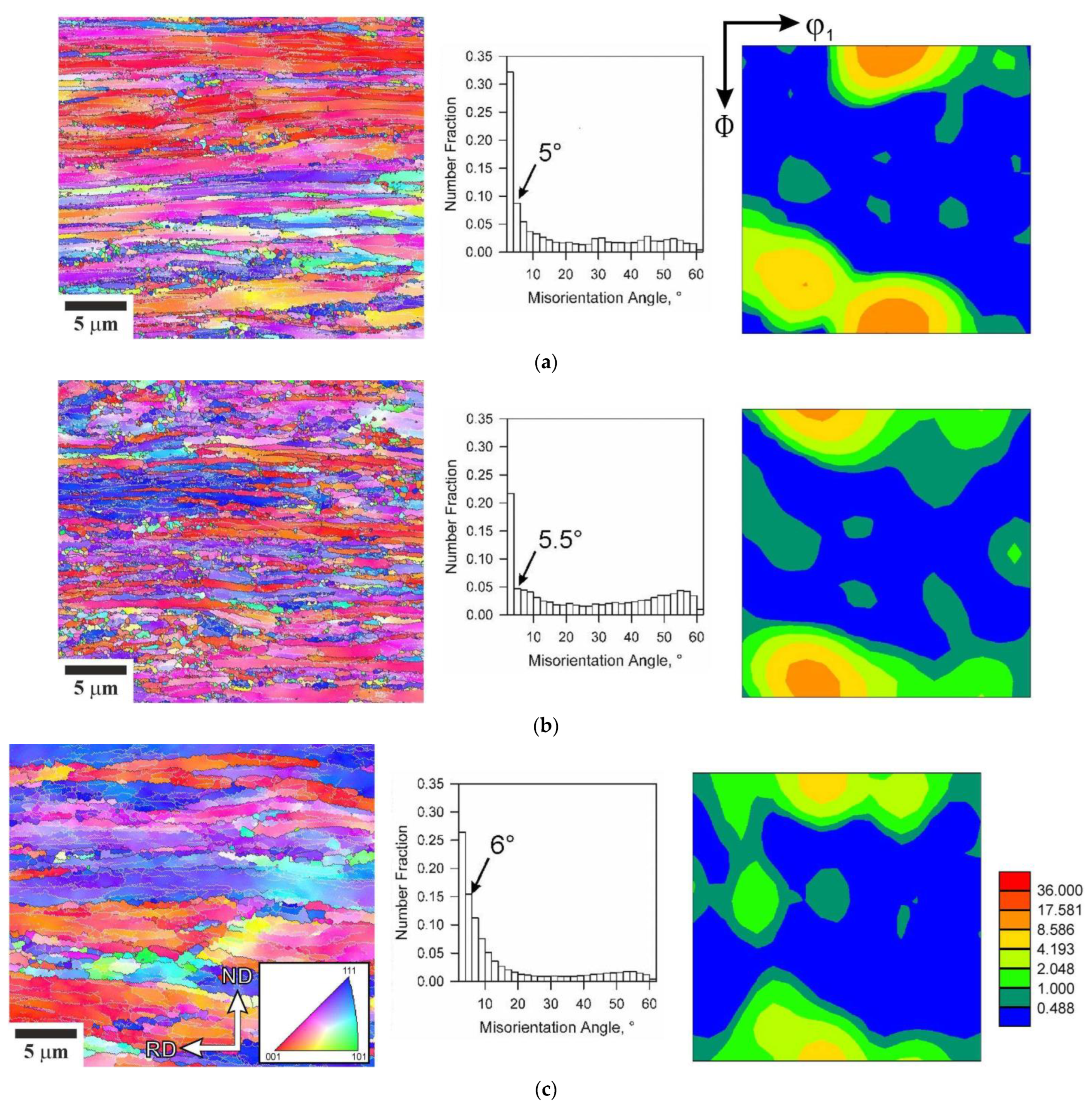
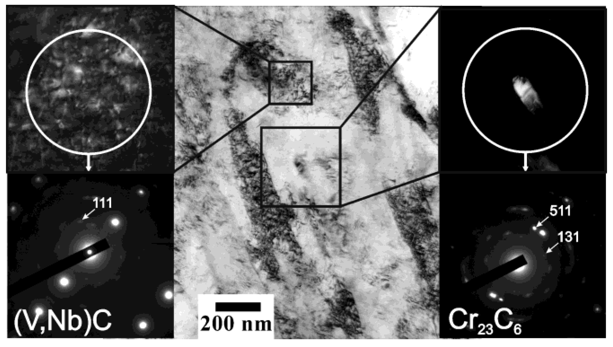
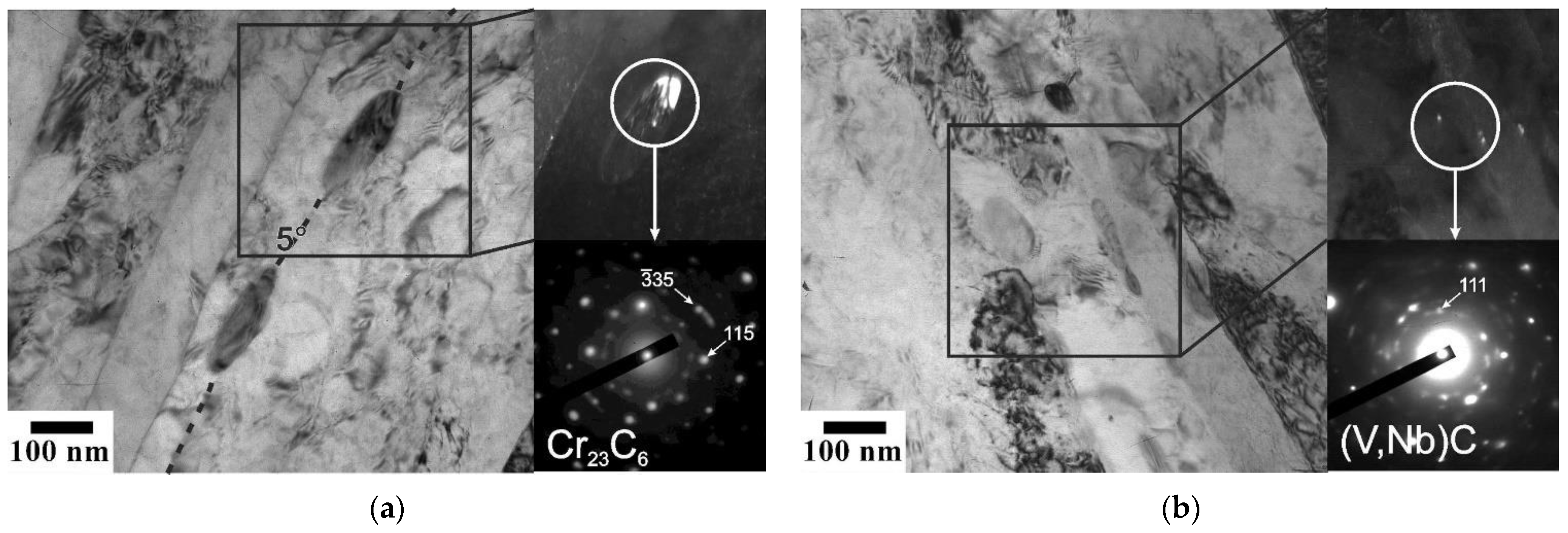
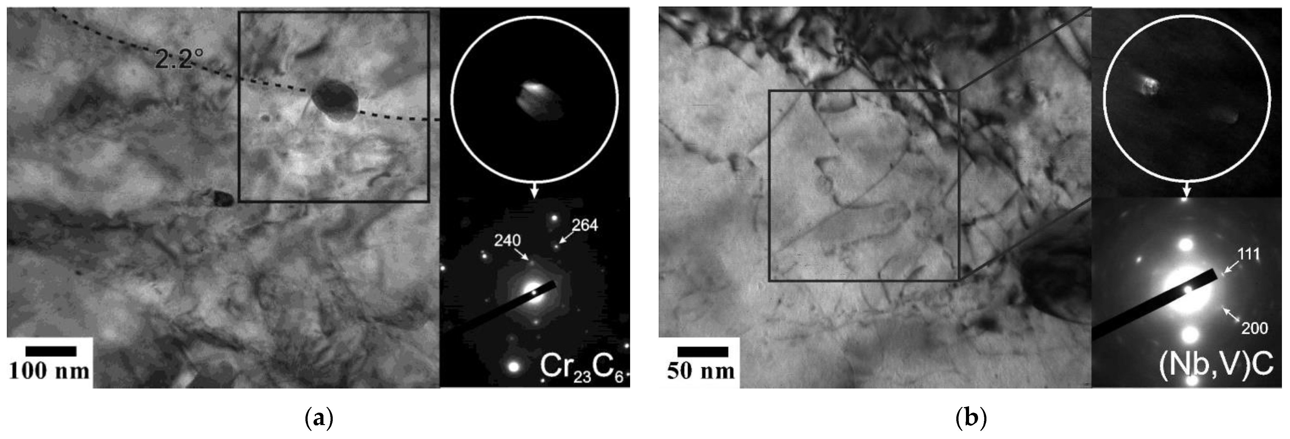
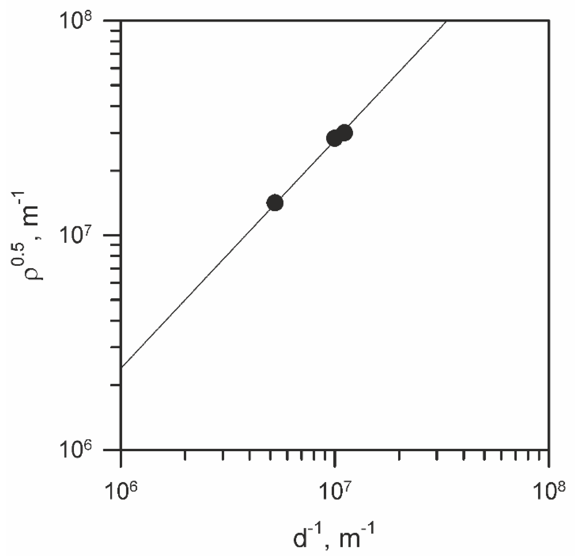
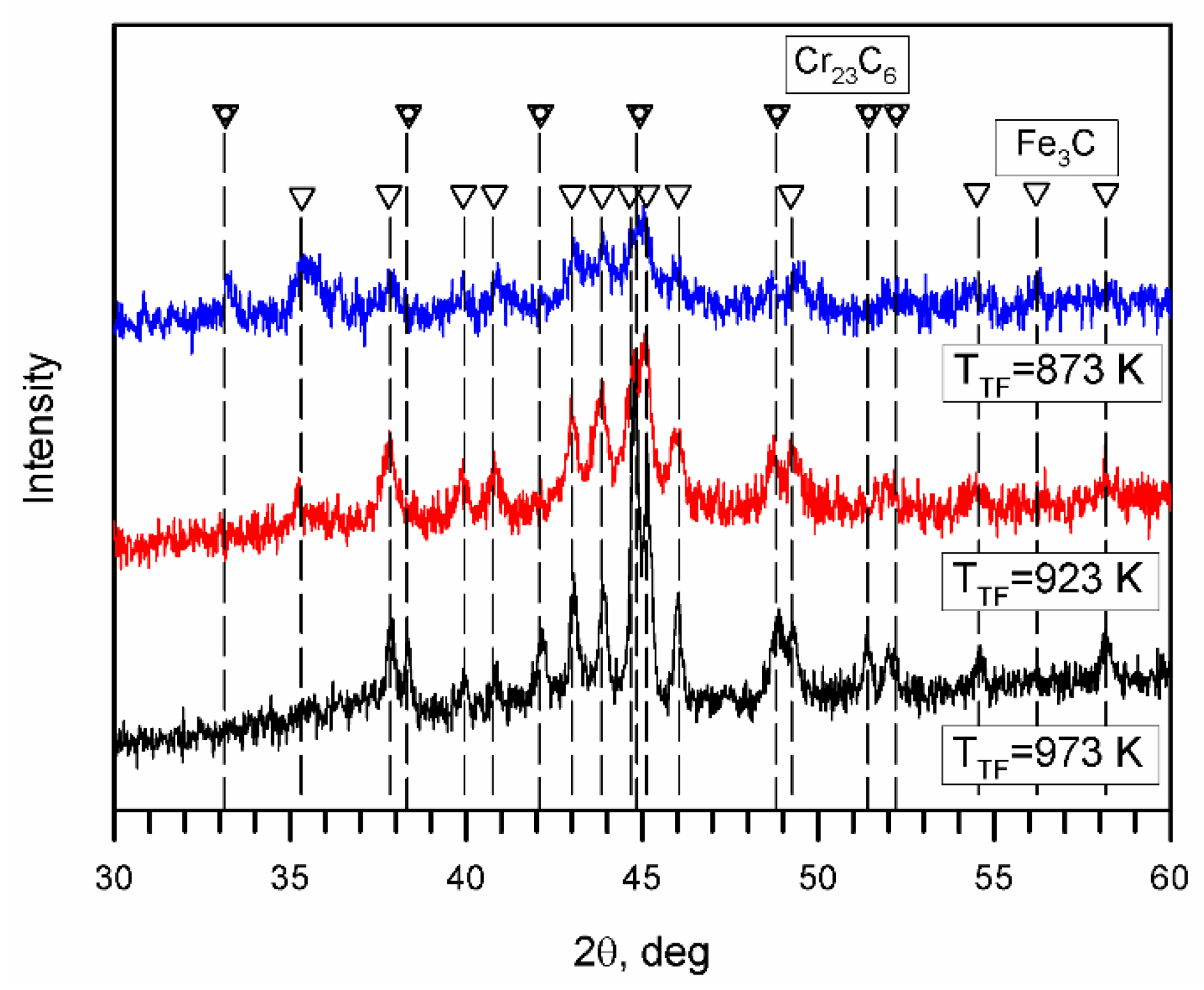
3.1. Microstructure after Tempforming

Typical microstructures evolved in the steel subjected to tempforming at different temperatures are shown in Figure 1. The deformation microstructures consist of highly elongated grains along the rolling direction. The grain boundaries appear as straight lines parallel to RD on the cross-section of the samples tempformed at 873 K (Figure 1a). In contrast, frequently wavy grain boundaries evolve in the sample processed at 973 K (Figure 1c) which suggests a pronounced recovery at relatively high tempforming temperatures. Thus, larger grains evolve at higher tempforming temperatures (Table 1). The grain/subgrain boundary misorientation distributions exhibit a sharp peak against small angles among a flat-type distribution with almost equal fractions of various HAB (Figure 1). An average sub-boundary misorientation slightly increases with tempforming temperature while the fraction of HAB decreases.
The sections of orientation distribution functions (ODF) at φ2 = 0° are also shown in Figure 1. The deformation textures evolved after tempforming include a strong {001}<110> (rotated cube) component, which has been frequently observed in plate-rolled bcc metals and alloys [11,12]. Rather strong {001}<110> texture component in the sample rolled at the lowest temperature of 873 K may be associated with strain accumulation under conditions of suppressed recovery [13]. An increase in the grain size with increasing tempforming temperature is accompanied by a weakening of the crystallographic texture. The maximal intensity of the deformation texture decreases almost threefold with an increase in rolling temperature.
Representative TEM images of the fine substructures that developed during tempforming are shown in Figure 2, Figure 3 and Figure 4. The transverse size (measured along ND) of deformation subgrains increases from 90 nm to 190 nm with an increase in temperature from 873 K to 973 K, whereas the dislocation density in grain/subgrain interiors decreases from 9 × 10¹⁴ m−2 to 2 × 10¹⁴ m−2 (Table 1). The relationship between these two substructural parameters is represented in Figure 5. It is clearly seen in Figure 5 that the transverse subgrain size can be related to the dislocation density inside subgrains through a power law function with an exponent of −0.5 much similar to other numerous studies on the dislocation substructures evolved in various metals and alloys during hot working [14,15,16]. It should be noted that the effect of tempforming temperature on the dislocation density and the subgrain size becomes stronger as temperature increases.
The martensite in the as-quenched steel was characterized by an average block size of 1.5 μm [8]. Rolling reduction in thickness of 78% suggests reducing the HAB spacing from 1.5 μm to 330 nm that is close to the transverse grain size evolved by tempforming at 873 K. However, the transverse grain size in the samples tempformed at higher temperatures is remarkably larger that implies grain/subgrain coarsening during tempforming, similar to that occurring upon continuous dynamic recrystallization when the grain size is solely controlled by deformation conditions [17]. Figure 6 shows the relationship between the transverse grain size and temperature-compensated strain rate during tempforming, using activation energy for self-diffusion in α–iron, Q = 239 kJ mol−1, for the sake of simplicity [18]. The present results are close to those obtained by Murty et al. for low-carbon steel processed under similar conditions [19]. Somewhat stronger temperature/strain rate dependence with an exponent of −0.3 observed in the present study as compared to that of about −0.1 observed in other steels during warm rolling [20] may result from Zener drag force exerted by the second phase particles.
The X-ray diffraction analysis of the powder residuals from the tempformed specimens suggests the presence of dispersed Fe3C and M23C6 particles (Figure 7); and the volume fraction of Cr23C6 phase increases from 0.15 to 0.6 in overall powder residual with an increase in the tempforming temperature from 873 to 973 K. Therefore, the following temperature precipitation sequence takes place:
M3C→M23C6
According to Thermo-Calc, the fraction of M23C6 carbides is about 0.012 at 873 K and decreases as temperature increases down to full disappearance at 973 K. Thermo-Calc expects precipitation of M7C3 (0.3% at 923 K and 0.7% at 973 K), i.e.,
M23C6→M7C3
Moreover, Thermo-Calc does not predict cementite at T ≥ 873 K. However, the replacement of M23C6 by M7C3 through the precipitation sequence (2) was not confirmed in the present study. It is apparent that M3C and M23C6 carbides possess fast precipitation kinetics and precede M7C3 even at a relatively high temperature of 973 K. Besides M23C6, Thermo-Calc predicts the precipitation of NbC and VC with volume fractions of about 0.0004 and 0.0009, respectively (total of about 0.0013 in Table 1). The small fraction of (Nb,V)C is below the critical limit for conventional X-ray diffraction analysis. However, both NbC and VC carbides were observed as tiny particles on TEM images, especially, at temperatures below 973 K (Figure 2 and Figure 3). Commonly, V-rich carbides exhibit plate-like or disc-type shapes and Nb-rich dispersoids are spherical in low-alloyed steels [5,21]. The TEM observations did not reveal any remarkable difference in the appearance of NbC and VC particles in the present study (Figure 2, Figure 3 and Figure 4). Therefore, both carbides were taken into account as (Nb,V)C particles for the strength calculation.
Characteristic examples of dispersed particles in the tempformed samples are shown in Figure 2, Figure 3 and Figure 4. The dispersed particles can be categorized into two size domains irrespective of processing temperature (Table 1). The fine particles are (Nb,V)C-type carbides with an average size of 4 to 17 nm depending on the temperature of tempforming. The coarse particles are represented by Fe3C and Cr23C6 carbides. The average size of the coarse particles increases from 40 nm to 90 nm with an increase in tempering temperature. The volume fractions of coarse particles in Table 1 (FCr23C6 and FFe3C) were calculated taking into account their relative fraction observed by X-ray diffraction (FCr23C6 X-ray/FFe3C X-ray) and assuming that their relative precipitation kinetics corresponds to the ratio of their possible volume fractions predicted by Thermo-Calc (FCr23C6 ThermoCalc/FFe3C ThermoCalc) assuming the presence of either Cr23C6 or Fe3C, i.e.:
(FCr23C6 ThermoCalc KCr23C6)/(FFe3C ThermoCalc KFe3C) = FCr23C6 X-Ray/FFe3C X-Ray
where KCr23C6 + KFe3C = 1
and FCr23C6 = FCr23C6 ThermoCalc KCr23C6, FFe3C = FFe3C ThermoCalc KFe3C
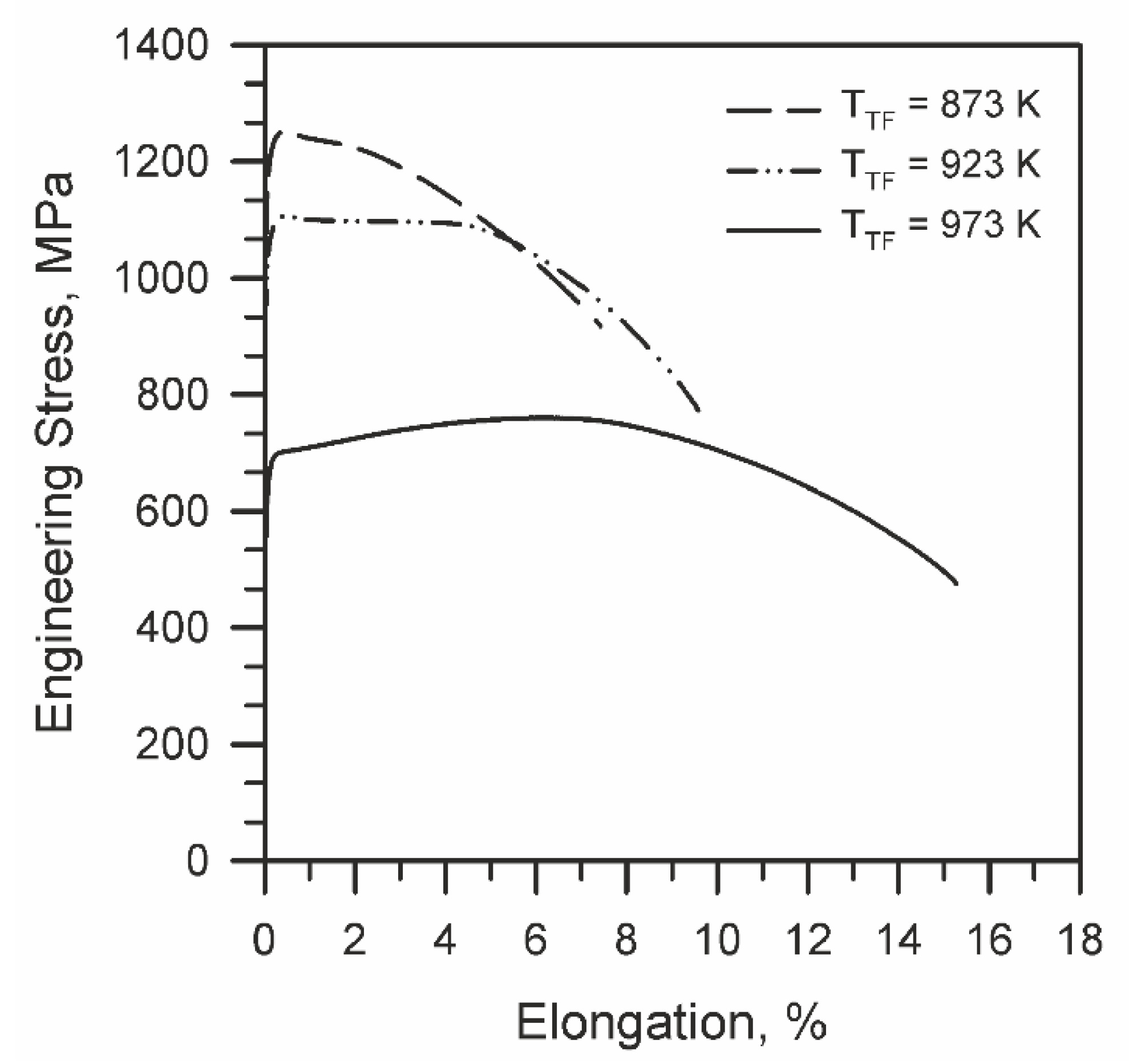
The volume fraction of the relatively coarse Fe3C and Cr23C6 particles calculated using X-ray data slightly decreases with a decrease in tempforming temperature. This may be attributed to incomplete precipitation at rather low tempering temperatures. Incomplete precipitation of Cr23C6-type carbide was observed in martensitic steel even at high-temperature tempering at 1023 K [22]. Therefore, the precipitation kinetics seems to be responsible for the suppression of Cr7C3 precipitation along with an increase in the fraction of Fe3C particles and a decrease in the volume fraction of coarse particles with a decrease in the tempforming temperature. On the other hand, the volume fraction of the finely dispersed (Nb,V)C particles is almost the same at all temperatures of tempforming, while their size fourfold decreases with a decrease in temperature from 973 K to 873 K. Hence, significant strengthening is expected from the finely dispersed (Nb,V)C particles, especially, at relatively low temperatures of tempforming. It is worth noting that the fine particles of MX carbides are uniformly spaced throughout ferrite, while the coarse particles of cementite and M23C6 are frequently located at low-angle sub-boundaries. Such distribution of dispersed particles suggests an Orowan mechanism for moving dislocations to interact with both fine and coarse particles.

3.2. Tensile Test

Engineering stress—strain curves are shown in Figure 8. Both the yield strength (σ0.2) and ultimate tensile strength (UTS) decrease while elongation increases with an increase in temperature of tempforming (Table 2). The steel processed at 873 K is characterized by a quite short stage of uniform elongation similar to those observed in work-hardened steels and alloys subjected to cold deformation [23,24]. Namely, following yielding at 1230 MPa, the tensile stress rapidly attains UTS of 1250 MPa and then gradually decreases upon necking. In contrast, the steel sample processed at 973 K exhibits remarkable strain hardening up to an elongation of 8%, although σ0.2 of 690 MPa and UTS of 760 MPa are relatively low. The steel tempformed at 923 K exhibits rather high σ0.2 and UTS of 1090 MPa and 1110 MPa, respectively, combined with a sufficient 5% uniform elongation and an elongation-to-failure of 10%. It is worth noting that the strength properties of the present steel samples are close to those observed in 0.4C-0.7Mn-0.24Si steel subjected to tempforming at 773 K followed by additional tempering at 823–973 K [25,26].

4. Discussion

Tempforming of the present HSLA steel results in significant strengthening as revealed by the tensile tests along RD. Note here, the tensile strength along RD and TD was shown to be almost the same for various steels subjected to large strain cold to warm plate rolling [27,28]. Therefore, the strengthening of the present steel samples can be roughly attributed to the developed microstructures that are characterized by the dispersed particles, the dislocation density, the transverse grain/subgrain size. Several different strengthening mechanisms may contribute to the yield strength of HSLA steels [2,3,5,29,30]. Among those, the grain size strengthening (σG), the dislocation strengthening (σρ), the dispersion strengthening (σOr), and the lattice friction including solid solution strengthening (σ0 + σSS) are to be considered for the present steel. The grain size strengthening can be expressed by the second term of the well-known Hall-Petch relationship [31,32].
σG = kyD−0.5
where D is the mean grain size and ky is the grain boundary strengthening factor of about 0.24 MPa m0.5 for low-carbon steels [29,33]. The dislocation strengthening, which is also known as work hardening, should obey the Taylor-type relationship [5,9,30].
σρ = αGbρ0.5
Here α is a constant of about 0.9 for low-alloyed steels [34], G and b are the shear modulus and the Burgers vector (81 GPa and 0.248 nm, respectively [18]), and ρ is the dislocation density. The strengthening by dispersed hard particles is generally attributed to an Orowan mechanism and can be evaluated by the following equation [35].
σOr = 0.2 MGb λ−1 (ln(d*/r0) + 0.7)
where λ = 0.2dP (π/FV)0.5 is the particle spacing for precipitates with an average size of dP and volume fraction of FV, M is the Taylor factor (2.75 for bcc-lattice), d* depends on the ratio between dP and λ and can be calculated as d* = (dP−1 + λ−1)−1, and r0 is the dislocation core size of approx. 2b. The strengthening from different types of precipitates can be evaluated as a square root of a sum of squares [36], i.e., σOr = (σOr12 + σOr22)0.5. The friction stress of σ0 = 45 MPa is usually adopted for yield strength calculation [5] and the solid solution strengthening of the present steel can be evaluated using Pickering’s empirical equation [5,37].
σSS = 32 Mn − 31 Cr +11 Mo + 5544 C
In this expression, the concentrations are expressed in wt.%. Other elements were not taken into account since their portions were negligibly small. The contents of carbon and substitutional solutes in ferrite were obtained by ThermoCalc.
The individual strengthener contributions calculated by Equations (4)–(7) are presented in Table 3. Irrespective of tempforming temperature, the highest contribution to the strength is provided by the dispersed particles. The total dispersion strengthening comprises 76% or 52% of the experimental yield strength after tempforming at 873 K, or 973 K. Note here that finely dispersed (Nb,V)C particles provide the major contribution to the total dispersion strengthening. The high dispersion strengthening is especially important for the steels intended for welded constructions because dispersed particles are favorable to stabilize the microstructures and properties in heat-affected zones of weld joints. Assuming that all strengthening mechanisms above are independent and linearly additive the yield strength could be calculated by a summation of all strengthening contributors. Such an approach gives a good correspondence between the calculated and experimental yield strengths for various annealed/recrystallized steels and alloys [5,10,30,38]. It is clear from Table 3, however, that this simple summation of all strengthening contributions results in significant (by about 1.5 times) overestimation of the yield strength. Moreover, the dislocation strengthening was calculated using only dislocations inside subgrains (indicated in Table 1), although it should take into account dislocations in low-angle sub-boundaries as well. The correct calculation of the dislocation strengthening can be carried out by using the following equation [39].
σρ* = αGb(1.5Svθ/b + ρ)0.5
Here θ and Sv are an average sub-boundary misorientation and the sub-boundary area per unit volume, respectively, and ρ is the dislocation density in subgrain interiors. Then, all strength contributions with the dislocation strengthening by Equation (8) give almost a twofold overestimation of the yield strength.
Recently, Takaki et al. concluded that the strengthening of work hardened steels is solely controlled by the dislocation density, which, in turn, depends on other strengthening factors [34]. It should be noted in Table 3 that the dislocation strengthening calculated by Equation (8) is almost the same as a sum of the grain size and dispersion strengthening. The yield strength, therefore, can be related to the dislocation strengthening or all other strengthening contributors, i.e., the grain size and dispersed particles in the present steel. Warm rolling upon tempforming is accompanied by an increase in the dislocation density, which controls the flow stress during warm deformation. On the other hand, strain hardening, i.e., increasing the dislocation density, depends on other strengthening mechanisms like grain boundaries and dispersed particles. In fact, the essence of strengthening is retardation of dislocation motion. The operation of various strengthening mechanisms provides a corresponding strain hardening rate lifting the dislocation density to a certain level, which determines the flow stress during plastic deformation. Considering the relationship between the grain size and the dislocation density of severely strained metals, Starink also suggested relating the strengthening with either the dislocation density or the grain size [40]. Thus, the strengthening of the present steel samples subjected to tempforming can be fairly evaluated by either a summation of the grain size and dispersion strengthening or just the dislocation strengthening.

5. Conclusions

The effect of tempforming (warm plate rolling following tempering) on the microstructure and tensile behavior of a low carbon HSLA steel was studied. The main results can be summarized as follows.
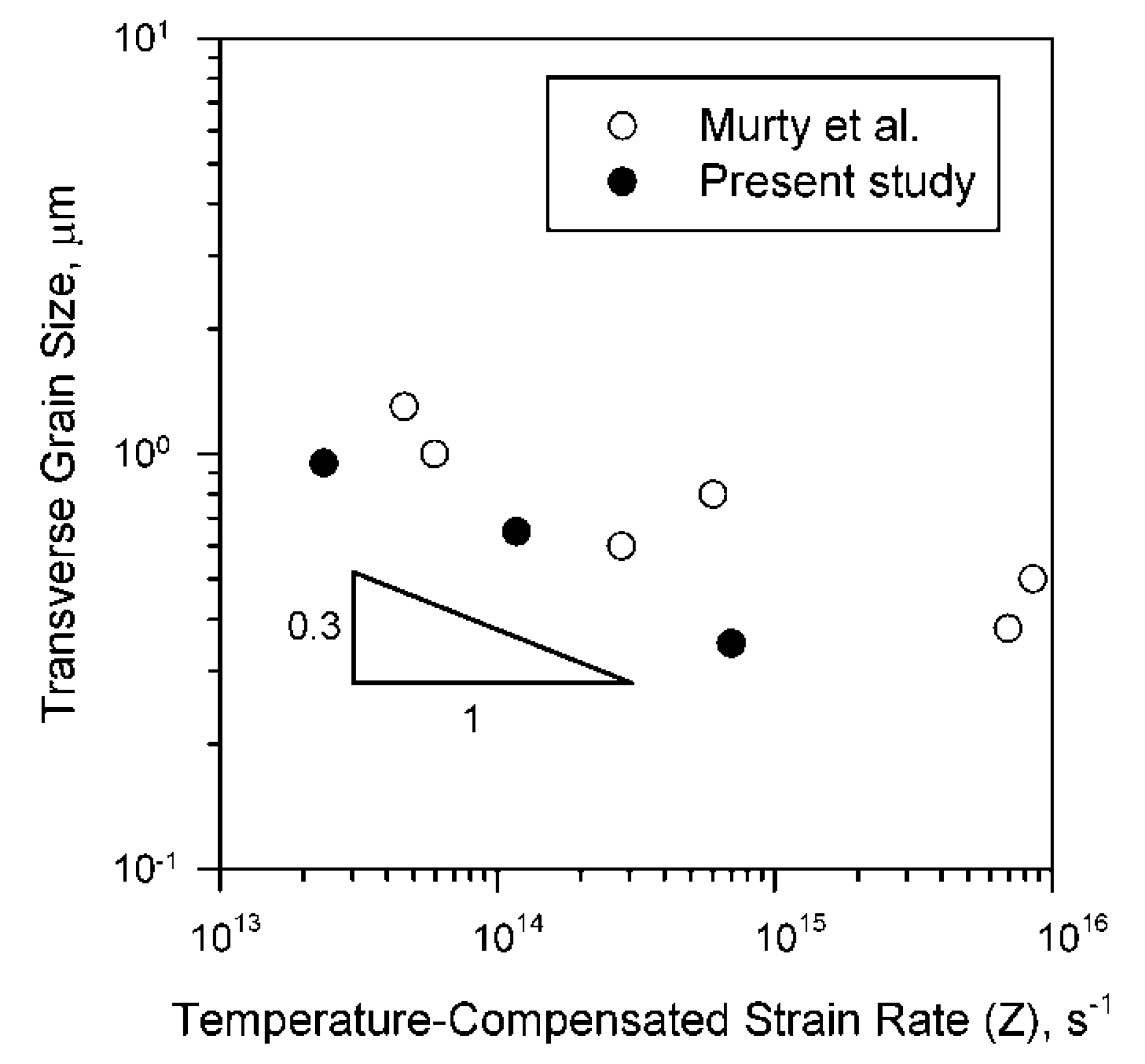
  • The tempformed steel samples were characterized by a lamellar-type microstructure composed of highly flattened grains with uniform distribution of dispersed carbide particles. An increase in tempforming temperature from 873 K to 973 K resulted in an increase in the transverse grain size from 350 nm to 950 nm in accordance with a power-law function of temperature-compensated strain rate. Correspondingly, the mean size of Cr23C6 and Fe3C carbide particles increased from 40 nm to 90 nm, while that of (Nb,V)C carbide particles increased from 4 nm to 17 nm.
  • The temperature of tempforming significantly affected the strength. Decreasing temperature from 973 to 873 K increased the yield strength from 690 MPa to 1230 MPa and the ultimate tensile strength from 760 MPa to 1250 MPa. The strengthening can be fairly expressed through either the dislocation density or the grain size and the dispersed particles.

Author Contributions

Conceptualization, R.K. and A.B.; methodology, A.D.; formal analysis, A.P. and S.G.; investigation, A.D.; writing—original draft preparation, R.K.; writing—review and editing, A.B.; supervision, R.K.; funding acquisition, S.G. All authors have read and agreed to the published version of the manuscript.

Funding

This study was financially supported by the Ministry of Science and Higher Education of the Russian Federation, Grant No. 075-15-2021-572 from 31 May 2021.

Data Availability Statement

The data presented in this study are available on request from the corresponding author.

Acknowledgments

The work was carried out using the equipment of the Joint Research Center of Belgorod State University «Technology and Materials».

Conflicts of Interest

The authors declare no conflict of interest.

References

  1. Krauss, G. Steels: Processing Structure and Performance; ASM International: Phoenix, AZ, USA, 2015; p. 681. [Google Scholar]
  2. DeArdo, A.J.; Hua, M.J.; Cho, K.G.; Garcia, C.I. On strength of microalloyed steels: An interpretive review. Mater. Sci. Technol. 2009, 25, 1074–1082. [Google Scholar] [CrossRef] [Green Version]
  3. Vervynckt, S.; Verbeken, K.; Lopez, B.; Jonas, J.J. Modern HSLA steels and role of non-recrystallisation temperature. Int. Mater. Rev. 2012, 57, 187–207. [Google Scholar] [CrossRef]
  4. Cochrane, R.C. Phase transformations in microalloyed high strength low alloy (HSLA) steels. In Phase Transformations in Steels, Vol.2: Diffusionless Transformations, High Strength Steels, Modelling and Advanced Analytical Techniques; Pereloma, E., Edmonds, D.V., Eds.; Woodhead Publishing: Cambridge, UK, 2012; pp. 153–212. [Google Scholar]
  5. Xiong, Z.; Timokhina, I.; Pereloma, E. Clustering, nano-scale precipitation and strengthening of steels. Prog. Mater. Sci. 2021, 118, 100764. [Google Scholar] [CrossRef]
  6. Kimura, Y.; Inoue, T.; Yin, F.; Tsuzaki, K. Inverse temperature dependence of toughness in an ultrafine grain-structure steel. Science 2008, 320, 1057–1060. [Google Scholar] [CrossRef] [PubMed]
  7. Dolzhenko, A.; Kaibyshev, R.; Belyakov, A. Tempforming as an advanced processing method for carbon steels. Metals 2020, 10, 1566. [Google Scholar] [CrossRef]
  8. Dolzhenko, A.; Yanushkevich, Z.; Nikulin, S.A.; Belyakov, A.; Kaibyshev, R. Impact toughness of an S700MC-type steel: Tempforming vs ausforming. Mater. Sci. Eng. A 2018, 723, 259–268. [Google Scholar] [CrossRef] [Green Version]
  9. Zhang, X.; Godfrey, A.; Huang, X.; Hansen, N.; Liu, Q. Microstructure and strengthening mechanisms in cold-drawn pearlitic steel wire. Acta Mater. 2011, 59, 3422–3430. [Google Scholar] [CrossRef]
  10. Zhang, D.; Zhang, M.; Cao, K.; Ning, J.; Feng, Y. Effect of annealing time on microstructure stability and mechanical behavior of ferrite-cementite steel with multiscale lamellar structure. Metall. Mater. Trans. B 2021, 52, 1023–1033. [Google Scholar] [CrossRef]
  11. Ray, R.K.; Jonas, J.J.; Hook, R.E. Cold rolling and annealing textures in low carbon and extra low carbon steels. Int. Mater. Rev. 1994, 39, 129–172. [Google Scholar] [CrossRef]
  12. Wenk, H.-R.; Houtte, P.V. Texture and anisotropy. Rep. Prog. Phys. 2004, 67, 1367–1428. [Google Scholar] [CrossRef]
  13. Kestens, L.A.I.; Pirgazi, H. Texture formation in metal alloys with cubic crystal structures. Mater. Sci. Technol. 2016, 32, 1303–1315. [Google Scholar] [CrossRef] [Green Version]
  14. Staker, M.R.; Holt, D.L. The dislocation cell size and dislocation density in copper deformed at temperatures between 25 and 700 °C. Acta Metall. 1972, 20, 569–579. [Google Scholar] [CrossRef]
  15. Takeuchi, S.; Argon, A.S. Steady-state creep of single-phase crystalline matter at high temperature. J. Mater. Sci. 1976, 11, 1542–1566. [Google Scholar] [CrossRef]
  16. Castro-Fernandez, F.; Sellars, C.M.; Whiteman, J.A. Changes of flow stress and microstructure during hot deformation of AI-1Mg-1Mn. Mater. Sci. Technol. 1990, 6, 453–460. [Google Scholar] [CrossRef]
  17. Sakai, T.; Belyakov, A.; Kaibyshev, R.; Miura, H.; Jonas, J.J. Dynamic and post-dynamic recrystallization under hot, cold and severe plastic deformation conditions. Prog. Mater. Sci. 2014, 60, 130–207. [Google Scholar] [CrossRef] [Green Version]
  18. Frost, H.; Ashby, M. Deformation Mechanism Maps; Pergamon Press: Oxford, UK, 1982; p. 166. [Google Scholar]
  19. Murty, S.V.S.; Torizuka, S.; Nagai, K.; Kitai, T.; Kogo, Y. Effect of initial grain size on evolved ferrite grain size during high Z large strain deformation. Mater. Sci. Technol. 2010, 25, 879–885. [Google Scholar] [CrossRef]
  20. Yanushkevich, Z.; Lugovskaya, A.; Belyakov, A.; Kaibyshev, R. Deformation microstructures and tensile properties of an austenitic stainless steel subjected to multiple warm rolling. Mater. Sci. Eng. A 2016, 667, 279–285. [Google Scholar] [CrossRef] [Green Version]
  21. Zhang, Z.; Zhang, J.; Lian, Y.; Ma, M.; Zhao, C.; Ye, Y.; Li, G.; Zhang, C.; Huang, J. Effects of vanadium content on the carbides transformation and strengthening mechanism of MPS700V hot-work die steel at room and elevated temperatures. Mater. Sci. Eng. A 2021, 813, 141091. [Google Scholar] [CrossRef]
  22. Tkachev, E.; Belyakov, A.; Kaibyshev, R. Creep behavior and microstructural evolution of a 9%Cr steel with high B and low N contents. Mater. Sci. Eng. A 2018, 725, 228–241. [Google Scholar] [CrossRef] [Green Version]
  23. Tsuji, N.; Okuno, S.; Koizumi, Y.; Minamino, Y. Toughness of ultrafine grained ferritic steels fabricated by ARB and annealing process. Mater. Trans. 2004, 45, 2272–2281. [Google Scholar] [CrossRef] [Green Version]
  24. Odnobokova, M.; Belyakov, A.; Kaibyshev, R. Grain refinement and strengthening of austenitic stainless steels during large strain cold rolling. Philos. Mag. 2019, 99, 531–556. [Google Scholar] [CrossRef] [Green Version]
  25. Kimura, Y.; Inoue, T. Influence of warm tempforming on microstructure and mechanical properties in an ultrahigh-strength medium-carbon low-alloy steel. Metall. Mater. Trans. A 2013, 44, 560–576. [Google Scholar] [CrossRef]
  26. Kimura, Y.; Inoue, T. Influence of carbon content on toughening in ultrafine elongated grain structure steels. ISIJ Int. 2015, 55, 1135–1144. [Google Scholar] [CrossRef] [Green Version]
  27. Miura, H.; Kobayashi, M.; Todaka, Y.; Watanabe, C.; Aoyagi, Y.; Sugiura, N.; Yoshinaga, N. Heterogeneous nanostructure developed in heavily cold-rolled stainless steels and the specific mechanical properties. Scr. Mater. 2017, 133, 33–36. [Google Scholar] [CrossRef]
  28. Belyakov, A.; Kaibyshev, R.; Torganchuk, V. Microstructure and Mechanical Properties of 18%Mn TWIP/TRIP Steels Processed by Warm or Hot Rolling. Steel Res. Int. 2017, 88, 1600123. [Google Scholar] [CrossRef]
  29. Takaki, S.; Akama, D.; Nakada, N.; Tsuchiyama, T. Effect of grain boundary segregation of interstitial elements on Hall–Petch coefficient in steels. Mater. Trans. 2014, 55, 28–34. [Google Scholar] [CrossRef] [Green Version]
  30. García-Sesma, L.; López, B.; Pereda, B. Effect of coiling conditions on the strengthening mechanisms of Nbmicroalloyed steels with high Ti addition levels. Mater. Sci. Eng. A 2019, 748, 386–395. [Google Scholar] [CrossRef]
  31. Hall, E.O. The deformation and ageing of mild steel: III Discussion of results. Proc. Phys. Soc. Sect. B 1951, 64, 747–753. [Google Scholar] [CrossRef]
  32. Petch, N.J. The cleavage strength of polycrystals. J. Iron Steel Inst. 1953, 174, 25–28. [Google Scholar]
  33. Belyakov, A.; Tsuzaki, K.; Kimura, Y.; Mishima, Y. Tensile behaviour of submicrocrystalline ferritic steel processed by large-strain deformation. Philos. Mag. Lett. 2009, 89, 201–212. [Google Scholar] [CrossRef]
  34. Tanaka, Y.; Takaki, S.; Tsuchiyama, T.; Uemori, R. Effect of grain size on the yield stress of cold worked iron. ISIJ Int. 2018, 58, 1927–1933. [Google Scholar] [CrossRef] [Green Version]
  35. Queyreau, S.; Monnet, G.; Devincre, B. Orowan strengthening and forest hardening superposition examined by dislocation dynamics simulations. Acta Mater. 2010, 58, 5586–5595. [Google Scholar] [CrossRef]
  36. Koppenaal, T.J.; Kuhlmann-Wilsdorf, D. The effect of prestressing on the strength of neutron-irradiated copper single crystals. Appl. Phys. Lett. 1964, 4, 59–61. [Google Scholar] [CrossRef]
  37. Gutierrez, I.; Altuna, M.A. Work-hardening of ferrite and microstructure-based modelling of its mechanical behaviour under tension. Acta Mater. 2008, 56, 4682–4690. [Google Scholar] [CrossRef]
  38. Harrell, T.J.; Topping, T.D.; Wen, H.; Hu, T.; Schoenung, J.M.; Lavernia, E.J. Microstructure and Strengthening Mechanisms in an Ultrafine Grained Al-Mg-Sc Alloy Produced by Powder Metallurgy. Metall. Mater. Trans. A 2014, 45, 6329–6343. [Google Scholar] [CrossRef]
  39. Hughes, D.A.; Hansen, N. Microstructure and strength of nickel at large strains. Acta Mater. 2000, 48, 2985–3004. [Google Scholar] [CrossRef]
  40. Starink, M.J. Dislocation versus grain boundary strengthening in SPD processed metals: Non-causal relation between grain size and strength of deformed polycrystals. Mater. Sci. Eng. A 2017, 705, 42–46. [Google Scholar] [CrossRef] [Green Version]
Figure 1. Microstructures developed in an HSLA steel subjected to tempforming at 873 K (a), 923 K (b) and 973 K (c) along with grain/subgrain misorientation distributions and sections of orientation distribution functions at φ2 = 0°. Colors correspond to the crystallographic direction along the normal direction (ND). The black and white lines indicate high-angle boundaries (θ ≥ 15°) and low-angle sub-boundaries (2° ≤ θ < 15°), respectively. Arrows on the misorientation distributions indicate an average sub-boundary misorientation.
Metals 12 00048 g001
Figure 2. Dispersed carbides in an HSLA steel subjected to tempforming at 873 K.
Metals 12 00048 g002
Figure 3. Particles of Cr23C6 (a) and (V,Nb)C (b) in an HSLA steel tempformed at 923 K. The number in (a) indicates the sub-boundary misorientation in degrees.
Metals 12 00048 g003
Figure 4. Particles of Cr23C6 (a) and (Nb,V)C (b) in an HSLA steel tempformed at 973 K.
Metals 12 00048 g004
Figure 5. Relationship between the subgrain size (d) and the dislocation density inside subgrains (ρ) in an HSLA steel subjected to tempforming at different temperatures.
Metals 12 00048 g005
Figure 6. Effect of deformation conditions on the transverse grain size in an HSLA steel subjected to tempforming (black symbols) and low carbon steel after large strain compression (open symbols) [19].
Metals 12 00048 g006
Figure 7. X-Ray diffraction of powder residuals obtained by a method of electrolysis from the tempformed specimens.
Metals 12 00048 g007
Figure 8. Tensile stress-elongation curves of an HSLA steel subjected to tempforming at indicated temperatures (TTF).
Metals 12 00048 g008
Table 1. Some microstructural parameters of an HSLA steel after tempforming.
Tempforming temperature, K873923973
Transverse grain size, nm350 ± 50650 ± 50950 ± 50
Longitudinal grain size, nm630 ± 50750 ± 501150 ± 50
Transverse subgrain size, nm90 ± 10100 ± 10190 ± 10
Dislocation density in subgrain interiors, m−29 ± 0.5 × 10148 ± 0.5 × 10142 ± 0.5 × 10¹⁴
Average sub-boundary misorientation, degree55.56
Sub-boundary area per unit volume, m−14.2 × 1063.4 × 1062.1 × 106
Cr23C6/Fe3C: particle size/volume fraction, nm/%40/0.8550/0.9190/0.94
(Nb,V)C: particle size/volume fraction, nm/%4/0.1297/0.13317/0.135
Table 2. Yield strength, UTS and total elongation after tempforming at different temperatures.
Tempforming temperature, K873923973
Yield Strength, MPa12301090690
UTS, MPa12501110760
Elongation-to-failure, %7.51015
Table 3. Contribution of different strengthening mechanisms to overall yield strength of the steel processed by tempforming at different temperatures.
Tempforming temperature, K873923973
Grain size strengthening, σG (MPa)343287234
Dislocation strengthening (dislocations inside subgrains), σρ (MPa)547515258
Dispersion strengthening by (Nb,V)C,821577305
Dispersion strengthening by Cr23C6/Fe3C, (MPa)456399253
Total dispersion strengthening, σOr (MPa)939701396
Solid solution strengthening, σSS (MPa)313547
Dislocation strengthening including dislocations in subboundaries, σρ* (MPa)1017955715
Publisher’s Note: MDPI stays neutral with regard to jurisdictional claims in published maps and institutional affiliations.

