
Improved Metallurgical Effect of Tundish through a Novel Induction Heating Channel for Multistrand Casting

School of Metallurgical and Ecological Engineering, University of Science and Technology Beijing, Beijing 100083, China
*
Author to whom correspondence should be addressed.
Metals 2021, 11(7), 1075; https://doi.org/10.3390/met11071075
Submission received: 2 June 2021
/
Revised: 26 June 2021
/
Accepted: 29 June 2021
/
Published: 5 July 2021
(This article belongs to the Special Issue Advanced Tundish Metallurgy and Clean Steel Technology)
Abstract
:Tundish with channel-type induction heating is one of new technologies adopted widely in China by the steel industry in the recent years, which can supply a constant liquid steel temperature control for the sequenced continuous casting process. For a five-strand tundish with induction heating in service, a kind of novel bifurcated split channel has been designed to solve the poor consistency of temperature and fluid flow for each strand that occurs with the conventional straight channel-type. The temperature distribution and fluid flow behaviors under the two structure modes were compared numerically by an electromagnetic-heat-flow multi-physics field coupling model. The results show that the maximum temperature difference between each strand outlet of the tundish can drop to less than 4 °C upon using the bifurcated channel, as compared to 10 °C under the original straight channel mode. According to the simulated results, case FK-A0 has been chosen as the optimized structure for industrial application. It has been verified through temperature measurements during the casting operation that the novel bifurcated split channel can improve the consistency of steel temperature for every strand of the tundish. The average temperature difference between the edge strand and the middle strand is 4.25 °C lower than the original straight channel, resulting in an upgraded metallurgical effect for the induction heated tundish.
1. Introduction
Special steels are key materials for engineering equipment manufacture, with strict requirements in the refining and casting process for the control of uniformity and purity [1,2]. As we know, the superheat of molten steel during the continuous casting is an important factor affecting the cast structure of steel semi-products and their quality consistency of different strands [3,4,5,6], while the tundish plays a crucial role in the casting process. Presently, T-shaped multi-strand tundish is widely adopted for billets casting during the production of special steel long products. Therefore, the stability of the molten steel temperature during sequence casting and the consistency of the casting temperature for the different strands are the key factors to evaluate the overall metallurgical behavior of the tundish. However, the superheat degree of molten steel in conventional tundish frequently fluctuates up to 10 °C or more due to heat loss in both the ladle and tundish during continuous casting. For a multi-strand tundish, an irrational flow control device will result in poor consistency in the casting temperature between each strand [7,8,9]. For this reason, the heating and temperature control technology has been given considerable attention for the improvement of tundish metallurgy [10,11,12]. Industrial practices show that tundish heating technology is an effective means to stabilize the casting temperature and realize continuous casting at constant casting speed in recent years [13,14,15]. As of now, there are two main temperature control measures for tundish through heat compensation of the power input: one is plasma guns, and the other is channel-type induction heating. The latter has been rapidly adopted in China in the past five years by the steel industry, owing to its service advantages of heating efficiency, working stability and lower noise, as compared with the former. Based on the electromagnetic induction principle, the induced current is generated in the molten steel moving through the channel, then produces joule heat to compensate its temperature drop from the final stage of a pouring ladle [16,17,18]. With the constant steel temperature in tundish, the casting operation under a given constant speed can be realized as well. However, it has also been noticed that the fluid dynamics and heat transfer behavior of molten steel in that tundish are much different from those of the traditional tundish due to the setting-up of induction channels and the behaviors of electromagnetic force and joule heat, so new requirements are put forward for the current channel structure and refractory life used in the induction heating tundish.
Originally, the induction heating tundish was invented by Ueda et al. [19] in 1984, and it was applied in Japan for special steel casting around 1990s. The application results show that the function of induction heating can not only reduce the superheat of molten steel, but also improve the cleanliness of molten steel and the surface quality of rolled steels [16,17]. Up to date, nearly all the induction heating tundishes employ single or dual channels, and most of them use a straight through type of channel structure. Additionally, there have been some mechanism studies on the flow field, temperature field and inclusion removal behavior with the induction heating tundish; however, most have utilized single strand or two-strand tundish as the investigated objects [20,21,22,23]. For example, Wang et al. [23] conducted a numerical simulation on a single strand tundish with the channel induction heating and pointed out that there is an upward flow at the exit of the channel due to thermal buoyancy, which changes the flow pattern of molten steel and promotes the temperature distribution more uniform in the tundish under the heating condition. For a two-strand tundish with twin channel induction heating, Yang et al. [24] found that there is a downward flow of molten steel at the exit of the channel after heated, and thermal buoyancy does not play a leading role compared with electromagnetic force and gravity. Xing et al. [25] investigated the impact of the channel inclination angle of a single-strand tundish on the flow of molten steel and found that when the inclination angle is 0°, there is an upward flow at the exit of the channel, while when the channel is inclined downward by 4° and 8°, the molten steel at the exit of the channel first descends and then rises. As a result, different researchers obtained various results due to the differences of tundish structure and channel design.
As is well known, a multi-strand continuous casting machine is generally adopted for long-product production of special steels. To ensure the stability and consistency of product quality, the temperature of molten steel and the temperature difference between different strands in tundish is required to be under strict control, while the temperature is closely related to the flow behavior of molten steel in tundish [26,27]. For the induction heating tundishes with the straight channel, many investigations have been performed by changing flow control device such as dams, weirs and turbulence inhibitors and setting optimal heating parameters to improve its flow and heat transfer behavior [28,29,30,31,32,33,34].
For a practical application, a five-strand induction heating tundish has been studied in the present paper to make the most advantage of its metallurgical behavior through an innovative channel design. It has been found that with an original conventional straight channel, the molten steel out of the channel mainly flowed to the edge of the tundish, resulting in the temperature difference measured between the edge strand and the middle strand was as high as 7–14 °C. In this situation, we should have to increase the actual casting temperature to avoid freezing of liquid steel during casting, which will limit the function of induction heating. For this consideration, the present study innovatively proposes a bifurcated split channel, which is supposed to improve the induction heating, fluid flow and temperature distribution behavior in the tundish. By establishing an electromagnetic-heat-flow multi-physics coupling model, the influence of both the bifurcated split angle of the channel and heating power on the flow, heat transfer of molten steel in the tundish has been studied and compared with the conventional straight channel. With a remarkably improved metallurgical behavior proven by industrial production, the study is expected to supply a novel design idea and application case for upgrading the channel-type induction heating tundish specially for quality steel production.
2. Mathematical Models
2.1. Geometric Model and Meshing
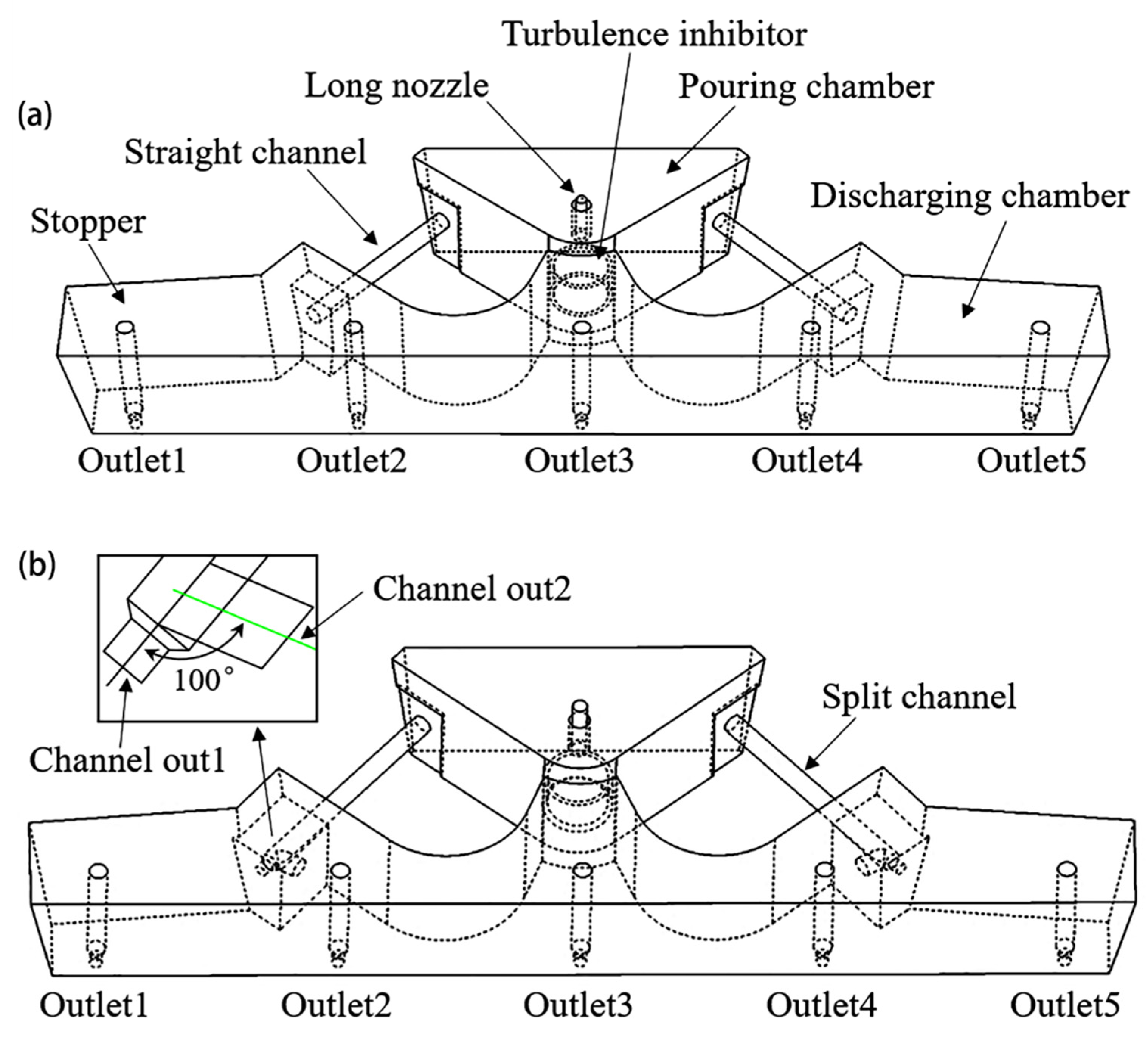
The tundish consists of a pouring chamber, two induction heating channels and a discharging chamber as shown in Figure 1. The molten steel from ladle flows into the pouring chamber through a ceramic nozzle, and then passes through the two channels to the discharging chamber, where it can be heated in need for an increased temperature by the induction coils. To simplify numerical simulation, half of the five-strand tundish, namely, 1st strand (Outlet1) to 3rd strand (Outlet3) are studied in the present work based on its symmetric geometry. Figure 1a illustrates the tundish with conventional upward inclined straight channels for heating by electromagnetic induction, which is named as straight channel case S0 in the modeling study. Then, a novel bifurcated channel is designed as shown in Figure 1b, where “Channel out1” represents the main channel same as the conventional straight one, 3° upward inclined; while the furcated “Channel out2” is introduced towards the middle area of discharging chamber with different inclination angles, which are named as split channel FK cases.
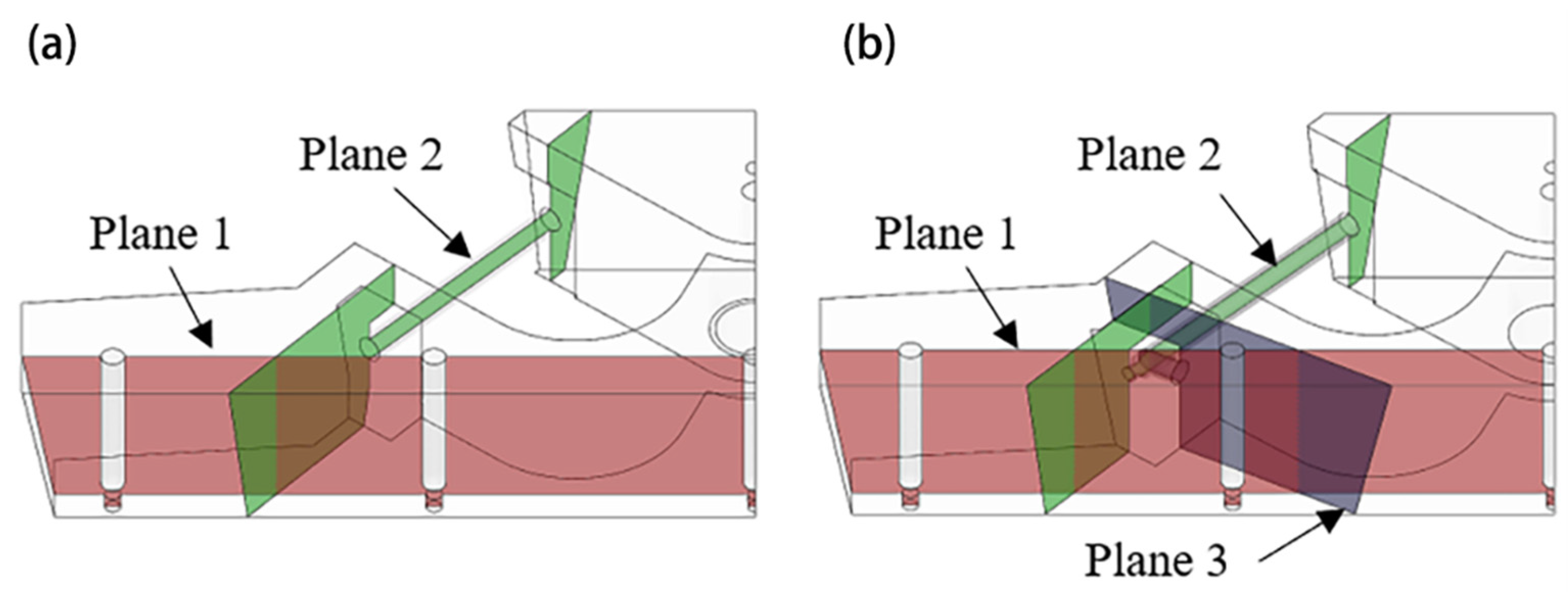
The induction heater consists of an iron core and a wounded induction coil, which is installed on the channel during service time of the tundish (not shown in the figure). The geometrical dimensions of the tundish for modeling are summarized in Table 1. For Channel out2, three split channel cases FK-A0, FK-A5 and FK-A15 are predetermined with an upward inclination angle 0°, 5° and 15°, respectively. As shown in Figure 2, the computational domains are discretized by using about 780,000 tetrahedral grids for S0 case and 800,000 for FK cases. The investigated sections for numerical analysis in these cases are illustrated in Figure 3, in which Plane 1, Plane 2 and Plane 3 represent the sections passing through the center of the three outlets of tundish, the “Channel out1” and “Channel out2”, respectively. The study plan for numerical analysis is given in Table 2.
2.2. Mathematical Modeling Assumptions
The following assumptions are adopted for the numerical simulation: (1) molten steel is an incompressible viscous fluid; (2) the influence of slag layer is ignored, and the top molten steel exposed to air is treated as a free surface; (3) the viscosity, permeability and thermal conductivity of molten steel are constant values, but the density against temperature is taken into account; (4) the molten steel will be polarized and magnetized immediately upon under the operation of electromagnetic field; and (5) the influence of displacement current is ignored.
2.3. Governing Equations
The electromagnetic field is calculated by the Maxwell equations during induction heating operation. The flow field is calculated by jointly using the continuity equation, the Navier–Stokes equation and the standard kε, and the energy equation is resolved to reveal the temperature field. The diffusion of tracers in the tundish is solved based on the mass transfer equation [20,29,34].
2.3.1. Control Equations of the Electromagnetic Field
2.3.2. Fluid Dynamics and Heat Transfer Equations
(1) Continuity equation
The continuity equation is also called the mass conservation equation. It must be obeyed when the fluid moves, which is expressed as:
where ρ is density of molten steel, ; is velocity of molten steel in i direction, ; xi is coordinate in i direction, m.
(2) Momentum equation
The momentum equation is to study the relationship between the change of momentum and the external force acting on the fluid when the fluid is in motion.
where p is pressure, Pa; μeff is effective viscosity, ; g is acceleration of gravity, ; is the source term of additional force, including thermal buoyancy and electromagnetic force, .
(3) Turbulence equation
Numerical simulation methods for turbulent motion mainly include Direct Numerical Simulation (DNS), Reynolds Average Navier-Stokes (RANS) and Large Eddy Simulation (LES). Among them, the two-equation model (kε model) in the RANS method is widely used in engineering for its less calculation and good accuracy. It is expressed as:
where k is turbulent kinetic energy; ε is turbulent energy dissipation rate; Gk is source term of turbulence energy; μ and μt are dynamic and turbulent viscosity coefficients, respectively, kg·m−1·s−1; C1ε, C2ε, Cμ, σk and σε are constants given by Launder and Spalding [35], and their values are taken 1.44, 1.92, 0.09, 1.0 and 1.3, respectively.
(4) Electromagnetic induction equation
The magnetic induction equation (MHD) derived from Ohm’s law and Maxwell’s equation can be used to describe the interaction between the magnetic field and the molten steel, which is numerically coupled with the fluid flow model.
The electromagnetic force is calculated by:
The current density can be expressed as:
where is the induced magnetic field by the motion of molten steel; μ is the magnetic permeability of molten steel, H·m−1; is external applied magnetic field; is electromagnetic force, .
(5) Energy equation
The energy equation is used to solve the temperature distribution of molten steel in the tundish.
where h is enthalpy, ; keff is effective thermal conductivity, ; T is temperature, K; S is the joule heat by the eddy loss of molten steel under the action of a magnetic field.
(6) Species transport equation
Species transport equation is used to simulate the transmission of the tracer in the molten steel, and the RTD curve is obtained to reflect the flow characteristics of the molten steel in the tundish.
where C is component volume concentration; Deff is component diffusion coefficient, taking default value 2.88 × 10⁻⁵ m2/s.
2.4. Boundary Condition and Solution Method
The boundary conditions for calculating the flow and heat transfer of tundish with the induction heating are set as follows. An insulation boundary condition is applied to the coil when calculating the electromagnetic field with a given eddy loss for the tundish. A related velocity is used at the inlet of the tundish, and its value is determined by the casting speed and the cross section of the billet castings. The inlet temperature of molten steel is set as 1800 K. An outflow boundary condition is applied to the tundish outlets, and the flow rate of each outlet is set as the same. The top of the tundish is free surface without shear stress; the solid wall is set as a no-slip boundary and a standard wall function has been adopted for the description of near wall region. Additionally, the heat loss of the tundish is caused by heat radiation and conduction. The parameters of molten steel, the boundary condition of the flow and the values of heat flux are shown in Table 3.
To solve the fluid flow and heat transfer of the tundish, the ANSYS (Version 19.2, ANSYS Inc., Pittsburgh, PA, USA) ICEM CFD software is first used to mesh the model, then the grid file is imported into the ANSYS Fluent software to calculate the temperature field and flow field. The SIMPLE algorithm is used for pressure-velocity coupling in the momentum equation. The convergence residuals are set to be less than 10−6 for energy equation and to be 10−4 for the other equations. When the flow field is converged to steady state, the solver is converted to the transient state to solve the transient tracer dispersion. The injection time of tracers at the inlet is set as 1 s. After that, its concentration variation with time is computed at the outlet plane of the tundish to obtain the residence time distribution (RTD) curve of tracers. The calculation time is set as 3000 s.
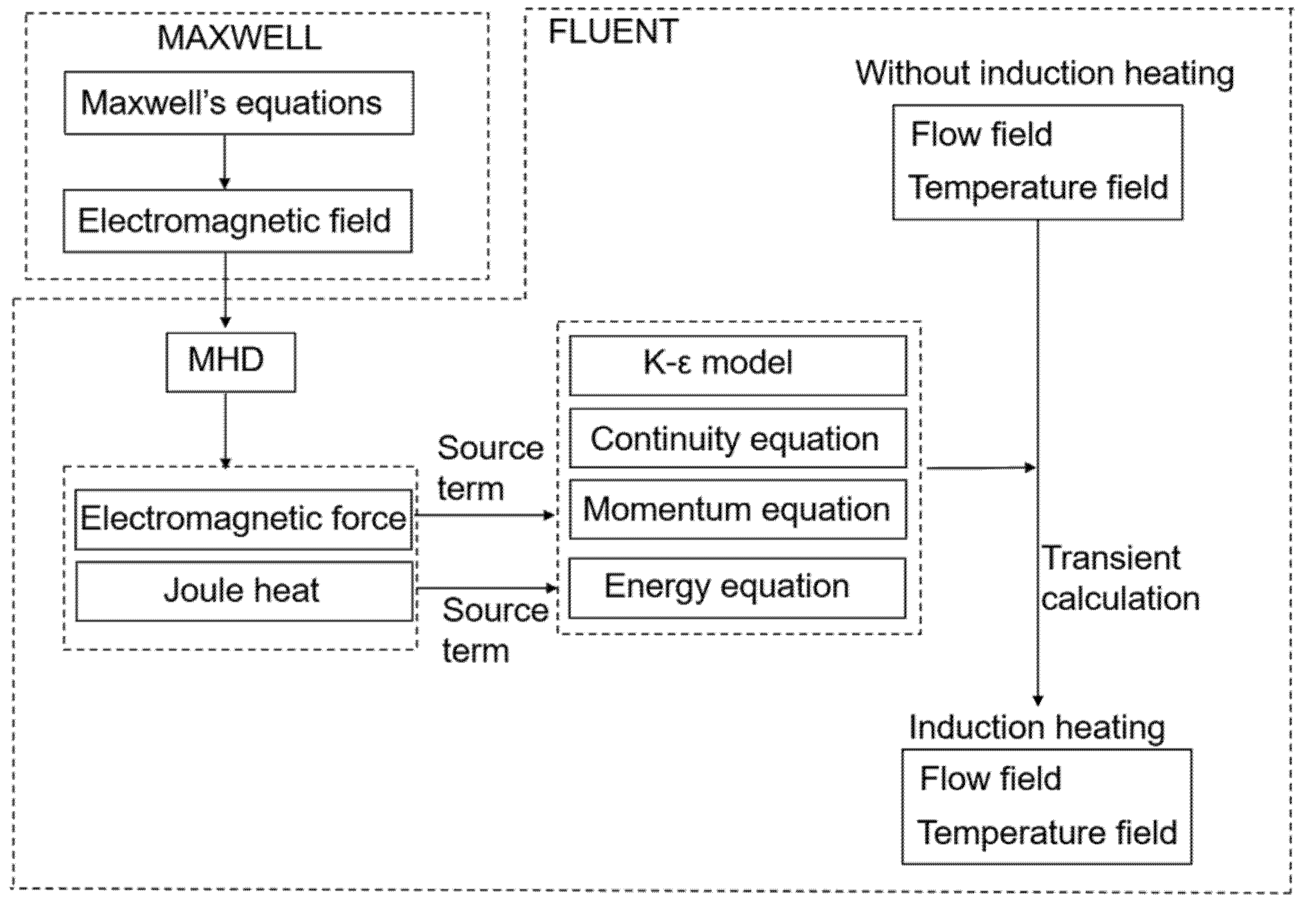
The coupling process of induction heating is illustrated in Figure 4. The Maxwell equations are solved by ANSYS MAXWELL finite element software to obtain magnetic field data, then these data are applied to the steady-state result of the tundish through the MHD module in the ANSYS Fluent software to calculate the electromagnetic force and joule heat. The electromagnetic force is added to the momentum equation as a source term, and joule heat is added to the energy equation. A multi-physics coupling model of electromagnetic-heat-flow is established to simulate the induction heating process. The multi-physics coupling numerical simulation achieved by MHD module is widely reported in metallurgical field, but it is less applied to the induction heating tundish.
In the previous studies, joule heat and Lorentz force are usually calculated by finite element software, which are then applied to the fluid model in ANSYS Fluent software by interpolation [22,23,34]. However, the fluid flow and heat transfer have not been considered when calculating joule heat and Lorentz force in this method. In the present work, we use the MHD module in Fluent to describe the transient flow of the molten steel under electromagnetic induction and to calculate the additional magnetic field generated by the fluid motion. This should be more accurate.
3. Results and Discussion
3.1. Grid Independence Test
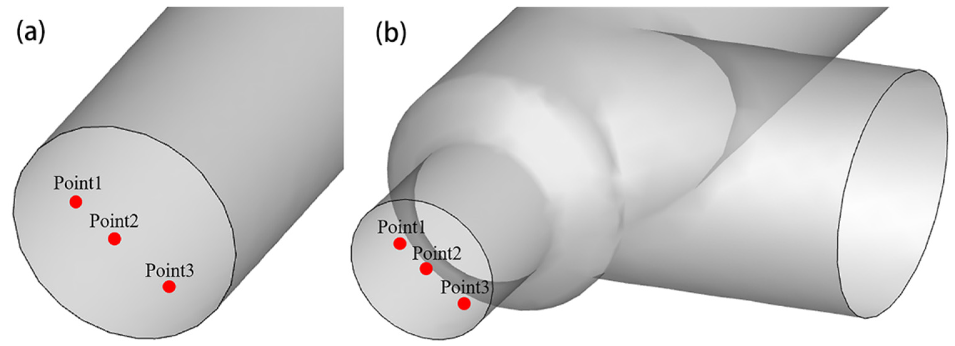
As well-known, the number of the grids in numerical simulation has a great influence on the final result. Too few grids will affect calculation accuracy, while too many grids will increase calculation time and cost. Therefore, it is necessary to choose the suitable number of grids. As shown in Table 4, 606,244, 779,156 and 3,718,389 grids are designed for case S0, and 487,767, 808,426 and 3,096,045 for case FK-A0, respectively. Under the same boundary conditions and parameters, the temperature at three reference points as illustrated in Figure 5 are calculated and compared at different number of grids, and the results are listed in Table 4. The three reference points are respectively set at the center of the channel exit section for S0 case and that of “Channel out1” for FK-A0 case, and 0.5r and 0.75r from the center of the channel, where r is the radius of the channel. It can be seen that with the increase in the number of grids, their temperatures change little. It indicates that the calculation accuracy can be met when the number of grids is 700,000~800,000. Therefore, the S0 case chooses 779,156 tetrahedral grids and FK cases choose about 800,000 for the following studies.
3.2. Model Validation
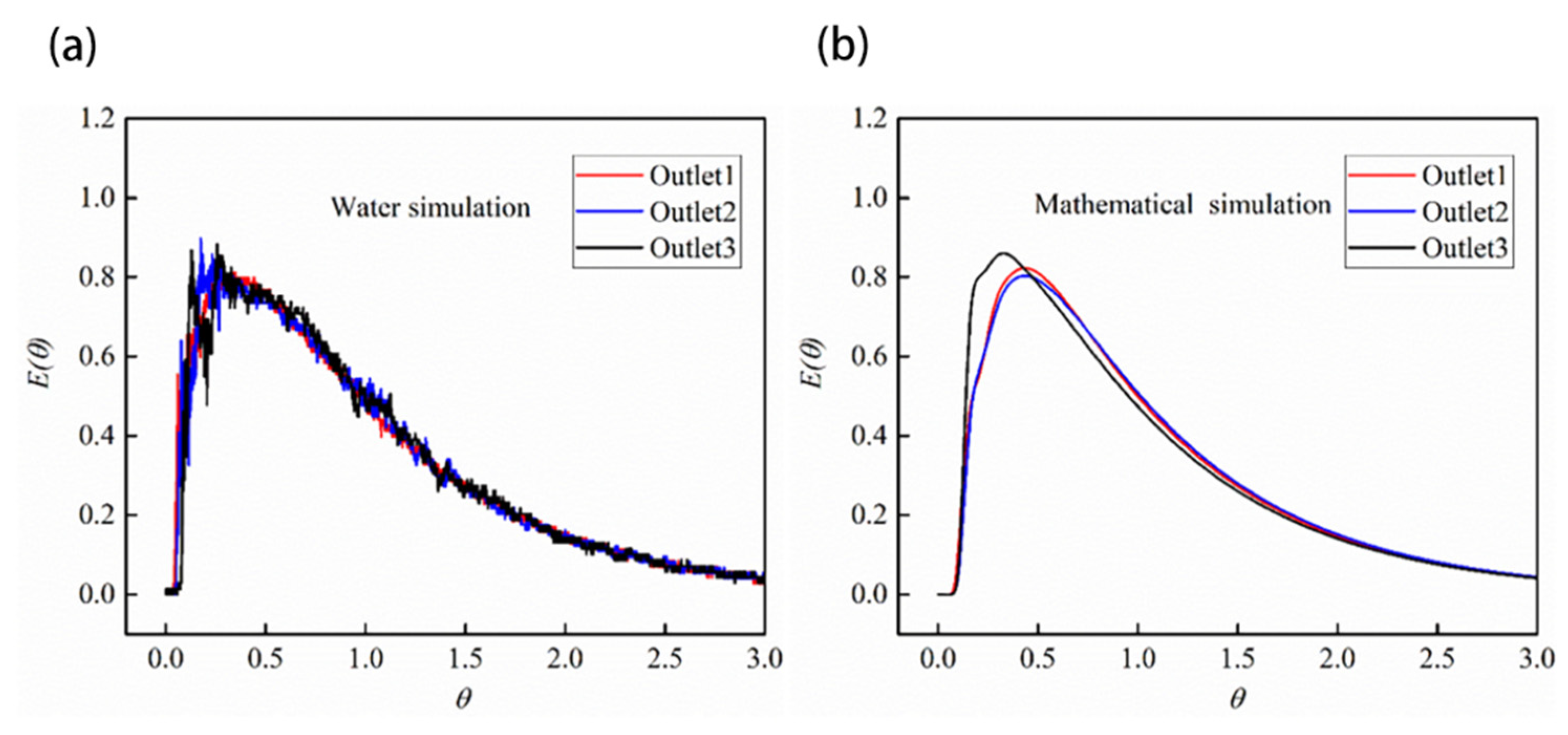
According to the metallurgical reaction engineering theory, the residence time distribution (RTD) of the tracer can be expressed by E(t) [28,29]. The abscissa t (unit s) is transformed into a dimensionless time θ = t/τ, thus the dimensionless E curve is transformed into , where τ is the theoretical average residence time of fluid in the reaction vessel (unit s). The RTD curves of the mathematical simulation and hydrodynamic modeling with a scale of 1:3 for the Outlet1 to Outlet3 of case FK-A0 are compared in Figure 6 when the induction heating is turned off. It is seen that their shapes and consistence among strands is very similar, although the values for time and concentration vary a little due to the differences of physical characteristic of tracers in water modeling and mathematical calculation.
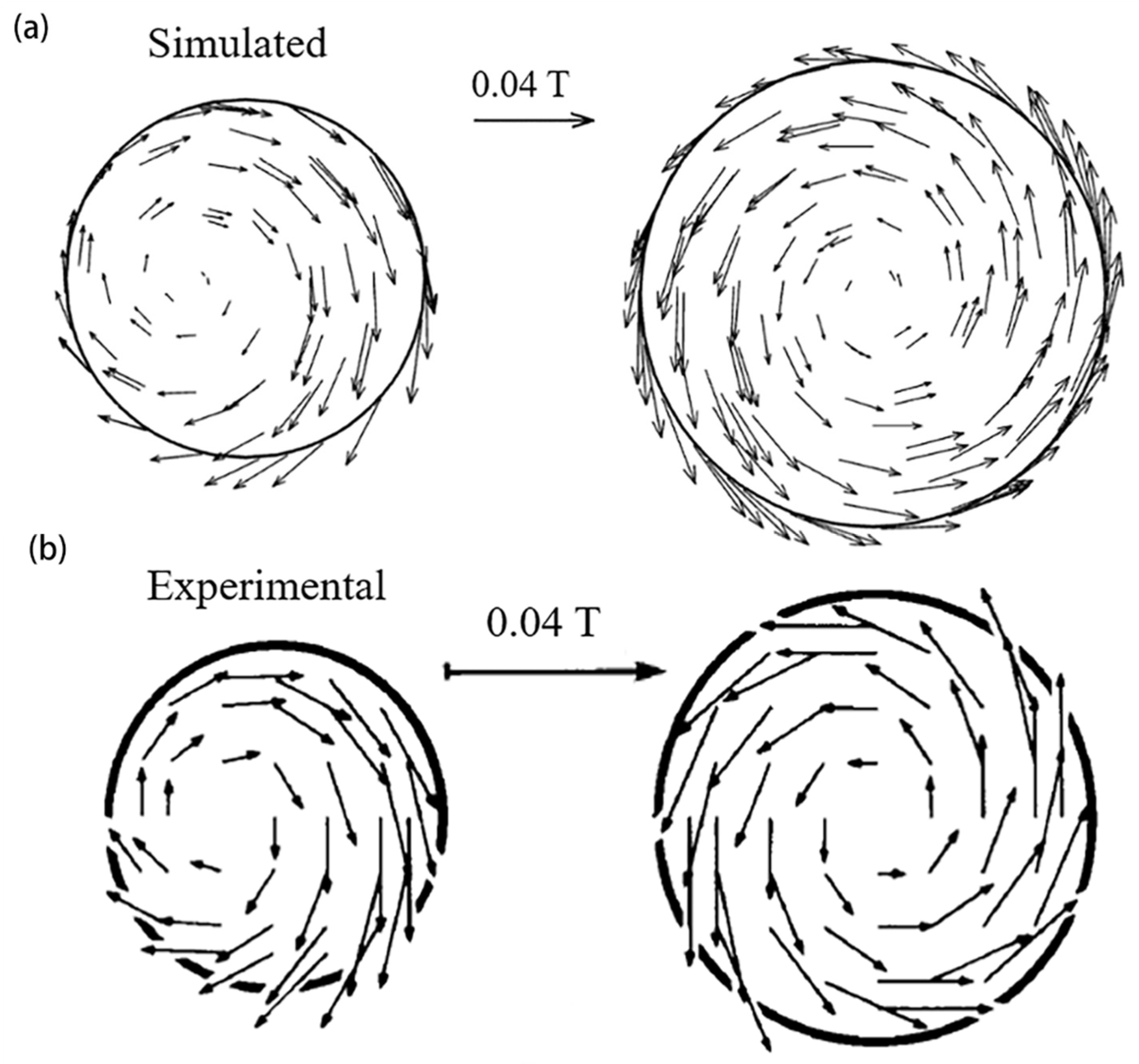
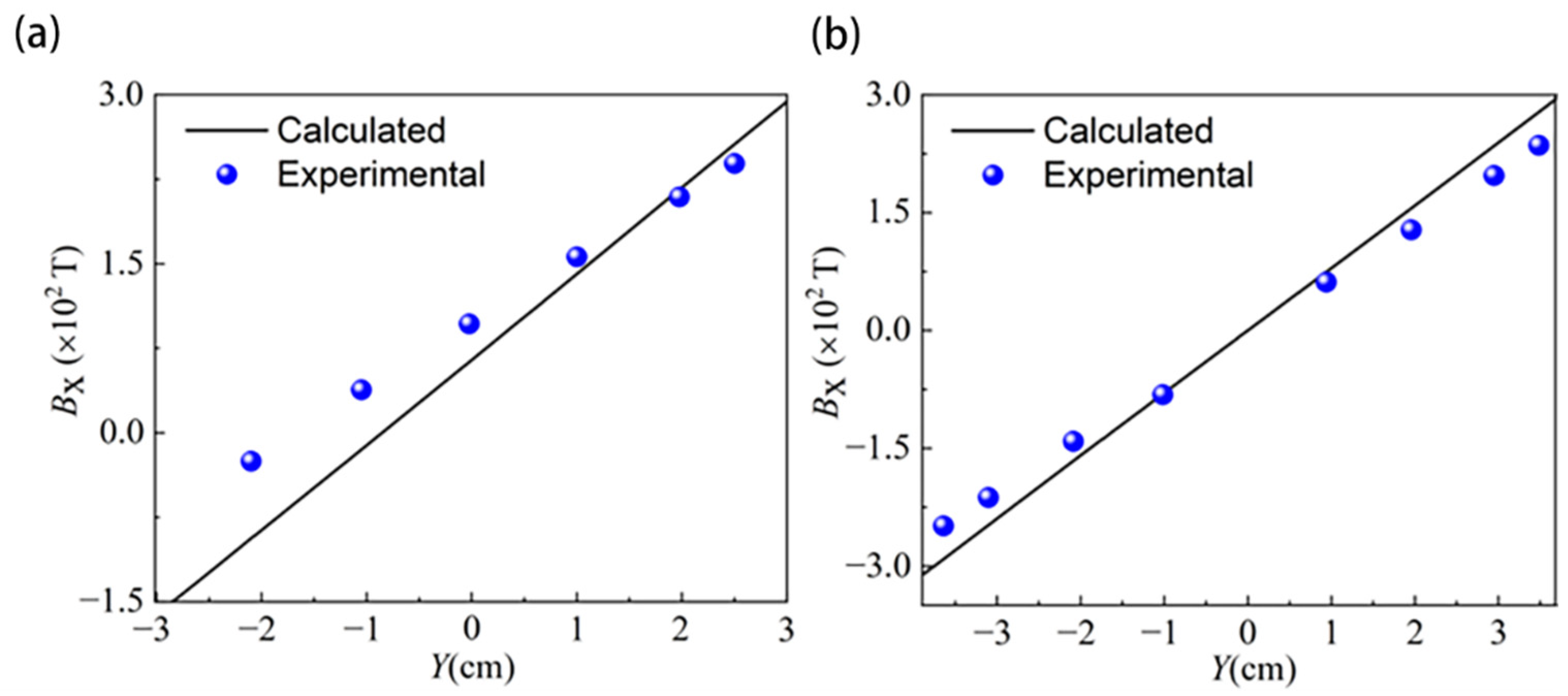
The electromagnetic field model is verified by the experimental results of Vives and Ricous [36], where an induction heating furnace model was established in the experiment, and the electromagnetic field distribution in the furnace was measured with liquid Hg as the medium. This model was similar to the structure of the channel induction heating tundish. The iron core was sleeved on the channel and a circulating induction current was formed inside the heating furnace to heat the metal Hg. In the present work, the model with the same size as the reference [36] is constructed and the same current parameters are applied. The vector distribution of the magnetic field on the Z = −20 cm channel section and the magnetic induction intensity in the Y direction are calculated. The comparison between simulation calculation and experiments is illustrated in Figure 7 and Figure 8. The similar magnetic field distribution and the magnetic induction intensity within the error tolerance certify the reliability of the electromagnetic field model established.
3.3. Electromagnetic Field and Joule Heat Distribution in Case S0 under Heating Power 1000 kW
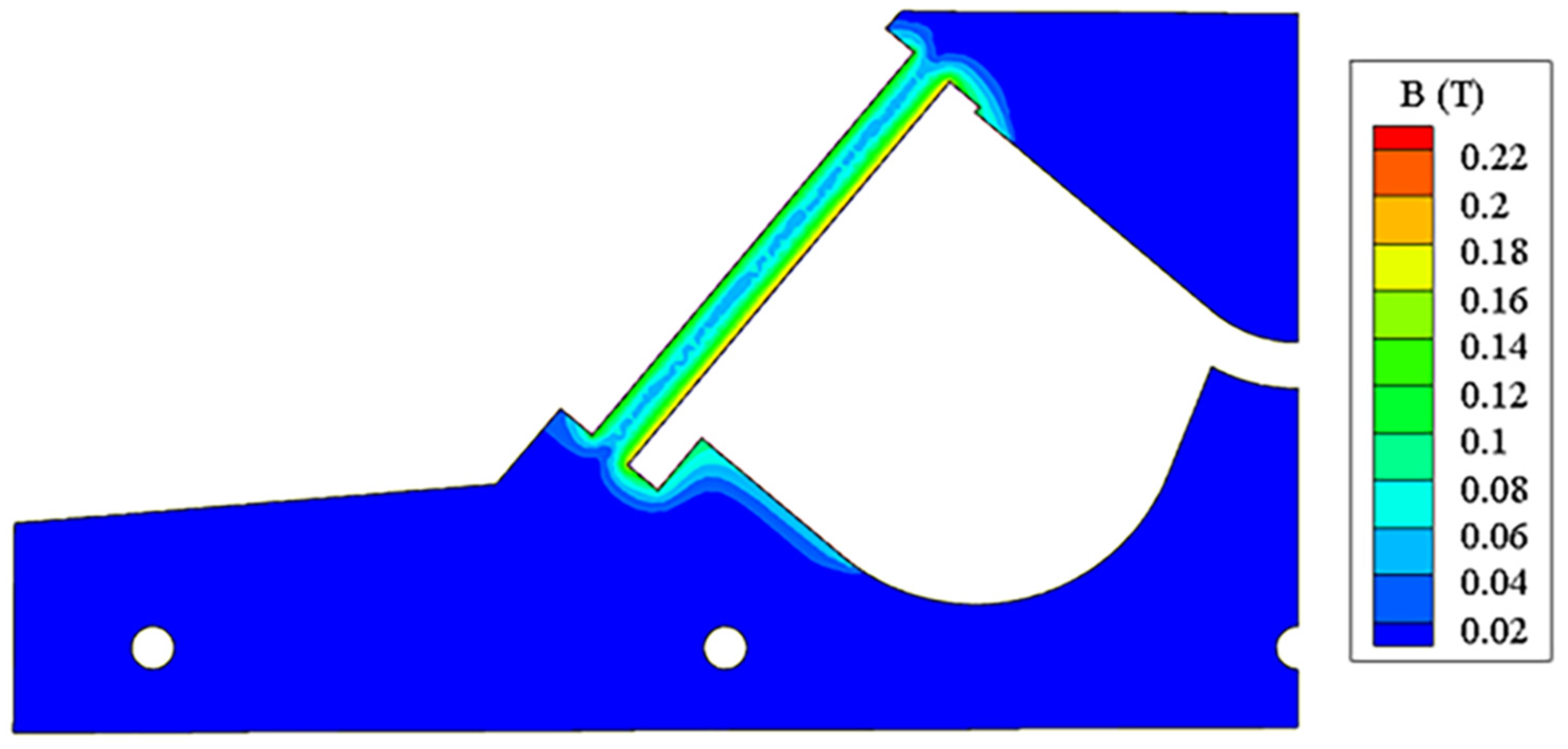
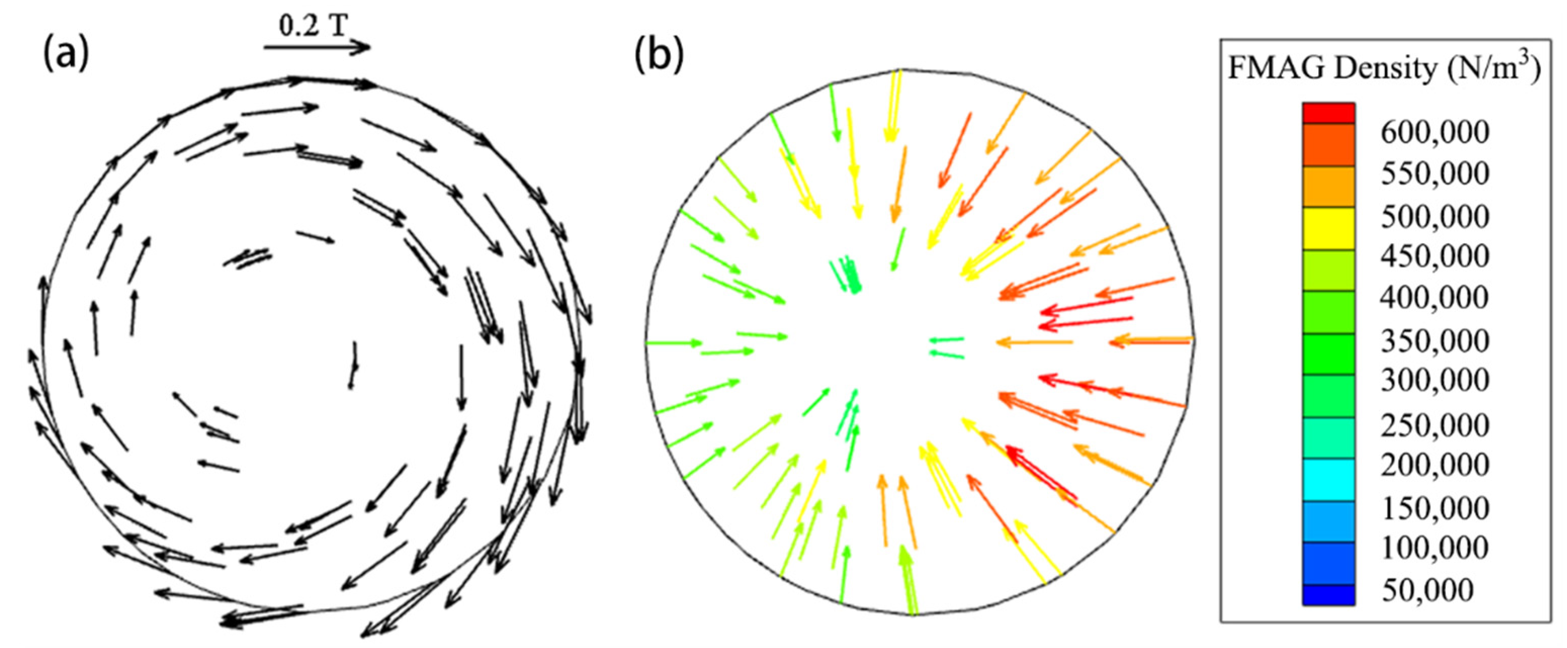
The magnetic field distribution in tundish for the case S0 is shown in Figure 9. It is mainly distributed in the heating channel and the areas near the entrance and exit of the channel, while the magnetic field intensities in the pouring chamber and the discharging chamber are below 0.02 T. The magnetic field intensity near the channel wall is greater than that at the center of the channel. It respectively reaches 0.18 T on the right channel wall and 0.12 T on the left channel wall, while it is only 0.06 T at the center of the channel due to “Kelvin skin effect”. The right wall has slightly bigger magnetic field intensity than the left as it is close to the heating coil, which generates “proximity effect”. Figure 10a is the vector distribution of the magnetic field intensity in the cross section of channel. It is eccentrically distributed in the channel section, and the magnetic field intensity near the channel wall is greater than that at the center of the channel. As shown in Figure 10b, the electromagnetic force is unevenly distributed and also points to the eccentric position of the channel, its “pinch effect” makes the conductive molten steel with a higher density constrict toward the center of the channel, while the non-conductive inclusions with a lower density swimming toward the wall of the channel under the action of electrophoretic force opposite to the direction of the electromagnetic force (the force generated by the gradient of the electromagnetic force) and then attaches to the wall of the channel to be removed from molten steel. Meanwhile, because of the pinch effect and eccentric electromagnetic force, the flow of molten steel in the channel is accelerated, and produces rotating in the channel and its exit, which will promote the homogenization of molten steel temperature, probably prolong the move path and increase the chances of collision, growth and floating removal of suspended inclusion particles as well.
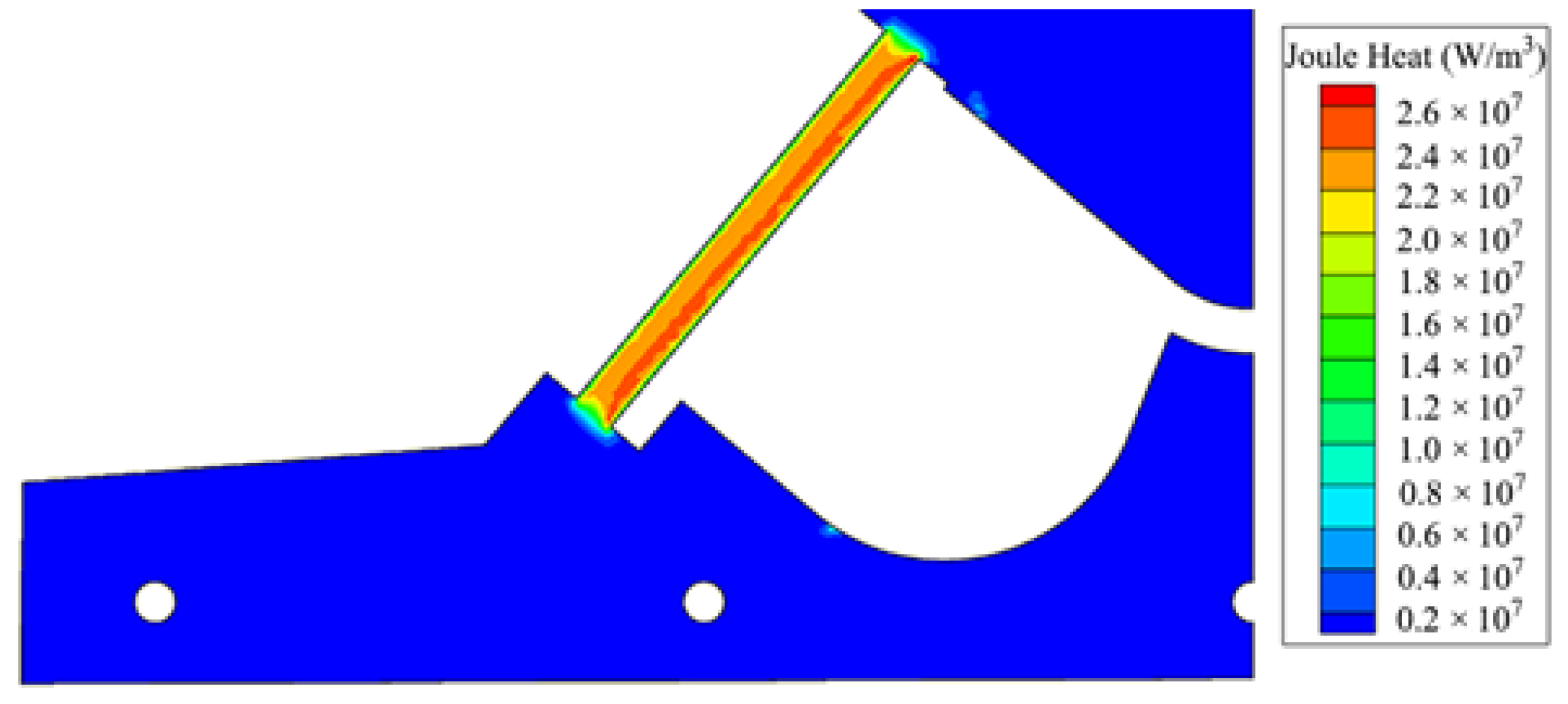
Figure 11 illustrates the distribution of joule heat in the tundish. Similarly, it is mainly distributed in the heating channel, thus the molten steel is thermally compensated herein. When the heated molten steel flows into the discharging chamber, the temperature of the molten steel in the entire tundish is enhanced. The temperature on the right wall of channel is higher than that on the left as the heater is close to the former side.
3.4. Comparison of Flow Field and Temperature Field in Tundish for Case S0 with and without Induction Heating
The flow field and temperature field of a tundish are important assessment indexes for its metallurgical effect. For a multi-strand tundish, the key is to suppress a short-circuit flow, and improve the flow consistency and reduce the temperature difference between different strands. The induction heating is not turned on at the beginning stage of pouring operation as the temperature of molten steel is high enough. It usually works in the middle and late stages of pouring when the temperature of molten steel drops to a certain degree due to heat losses. The flow and heat transfer in tundish are obviously various with and without induction heating. Therefore, the two practical pouring conditions should be considered comprehensively for a good design of the induction heating tundish. In this part, the flow and heat transfer characteristics of molten steel in the tundish are compared under different operating conditions for the case S0, and the influence of induction heating on the metallurgical effect of the tundish is revealed as well.
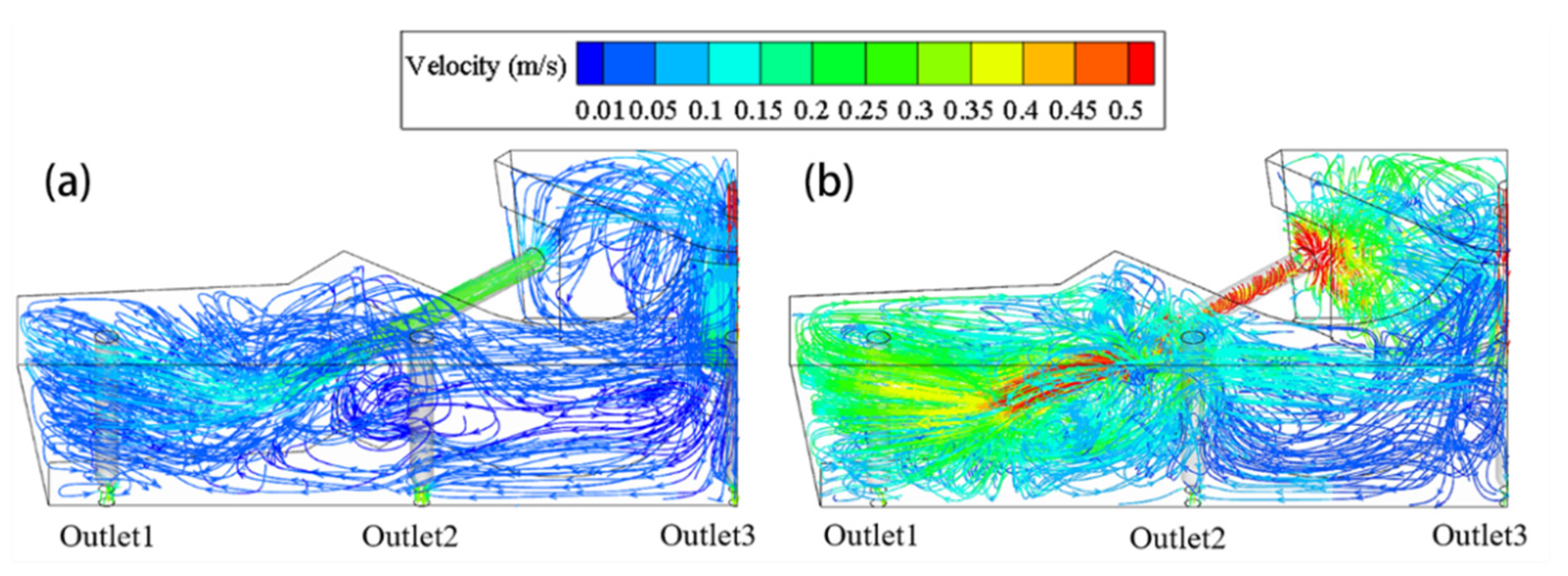
Figure 12 is the comparison of the flow field in the tundish when induction heating is turned off and turned on for 200 s at 1000 kW. Our previous studies show that the difference of molten steel in flow and heat transfer behaviors in the early stage of heating is bigger than in the late stage [29], thus take 200 s for comparison. When it is turned on, the flow velocity of molten steel in the entire tundish including the pouring chamber, channel and discharging chamber is all bigger than that it is turned off. The flow velocity in the channel is above 0.5 m/s, which is about twice as when it is turned off, and the molten steel shows a spiral movement trend, this is because that the molten steel in the tundish is subjected to eccentric electromagnetic force as shown in Figure 10 after the induction heating is turned on. This flow mode will increase the contact probability of the inclusions in the molten steel with the channel wall, which accordingly enhance the adsorption of wall on the inclusions. The pinch effect produced by electromagnetic force will also increase the collision probability of inclusions. However, more stringent requirements are put forward for channel refractory, as this flow mode will probably increase the erosion of channel.
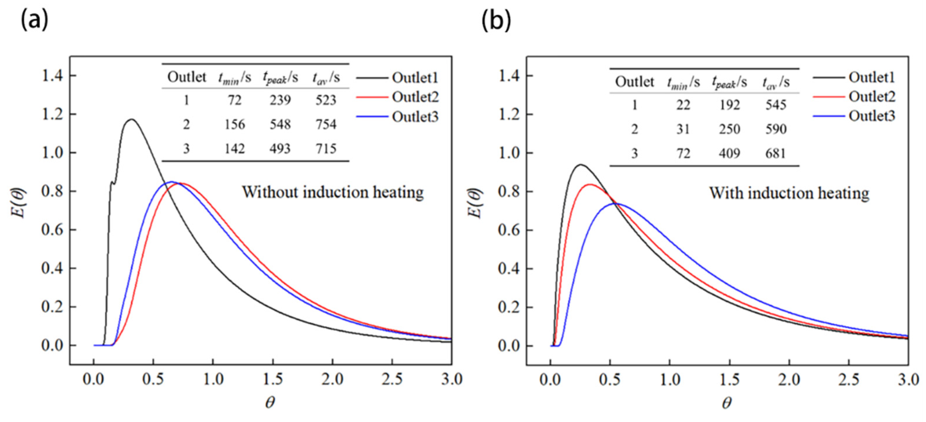
It is also seen from Figure 12 that the molten steel goes directly to the front wall of the tundish after flowing out of the channel. Due to bigger flow velocity from electromagnetic force, the corrosion of molten steel on the tundish refractory will also intensifies, and accordingly the cleanliness of molten steel may worsen. In addition, the short-circuit flow is easily formed at the Outlet1, because the channel exit of the case S0 is biased toward the Outlet1 and the molten steel flows out from here firstly. The Outlet3 is located in the middle of the tundish, far from the exit of the channel, thus the molten steel will arrive late, which is easy to form the dead zone herein. This is verified by the RTD curve shown in Figure 13, where tmin, tpeak and tav represent the respond time of molten steel, the peak time and the actual average residence time, respectively. They are obtained according to the method in Reference [37].
From Figure 13, the response time of Outlet1 is obviously shorter than that of Outlet3 whether with or without induction heating. As a result, the flow consistency of different strands in tundish is poor. As is well known, the temperature field of a tundish is closely related to its flow field, which a poor flow consistency will result in a large temperature difference and billet quality difference between strands. This explains why the temperature difference reaches 7 to 14 °C in the actual tundish operation. It can be seen by comparing Figure 12a,b, the flow in the middle area of the tundish will be improved after induction heating is turned on, since the up-rising flow at the exit of channel is more obvious under the action of joule heat, and the flowing of molten steel on the top of tundish is more active. From Figure 13b, Outlet2 shows the close response time of molten steel to Outlet1, which is 31 s and 22 s, respectively. Additionally, the difference of response time between Outlet1 and Outlet3 reduces from 70 s (142 − 72 s) to 50 s, compared with Figure 13a. The electromagnetic force makes part of the molten steel to move downwards with the increasing flow velocity as shown in Figure 12b, which results in the response time of molten steel shortened under induction heating.
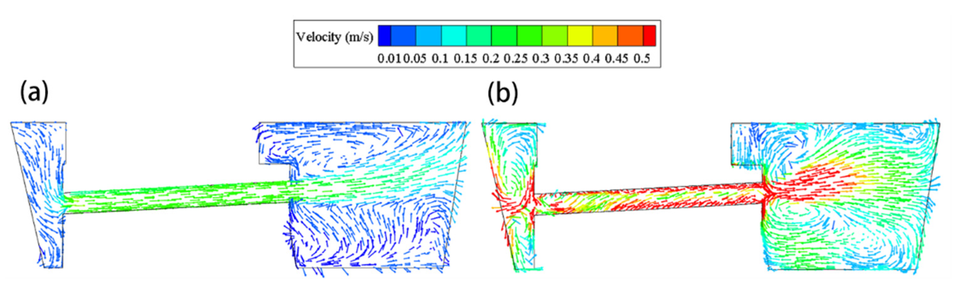
The velocity vector in the longitudinal section of channel for case S0 without and with induction heating is shown in Figure 14. From Figure 14a, the flow velocity of molten steel in the channel is about 0.3 m/s and directs to the channel exit when the induction heating is turned off. The molten steel has an upward tendency after flowing out of the channel and produces a circulating flow above the channel exit due to the upward inclination (3°) of the channel and the effect of thermal buoyancy. As shown in Figure 14b, after induction heating for 200 s, the velocity of molten steel in the channel is significantly increased and the overall flow field is more active. Due to the eccentric electromagnetic force, the molten steel in the channel rotates and flows forwards, and its flow velocity near the wall of the channel is as high as 0.5 m/s.
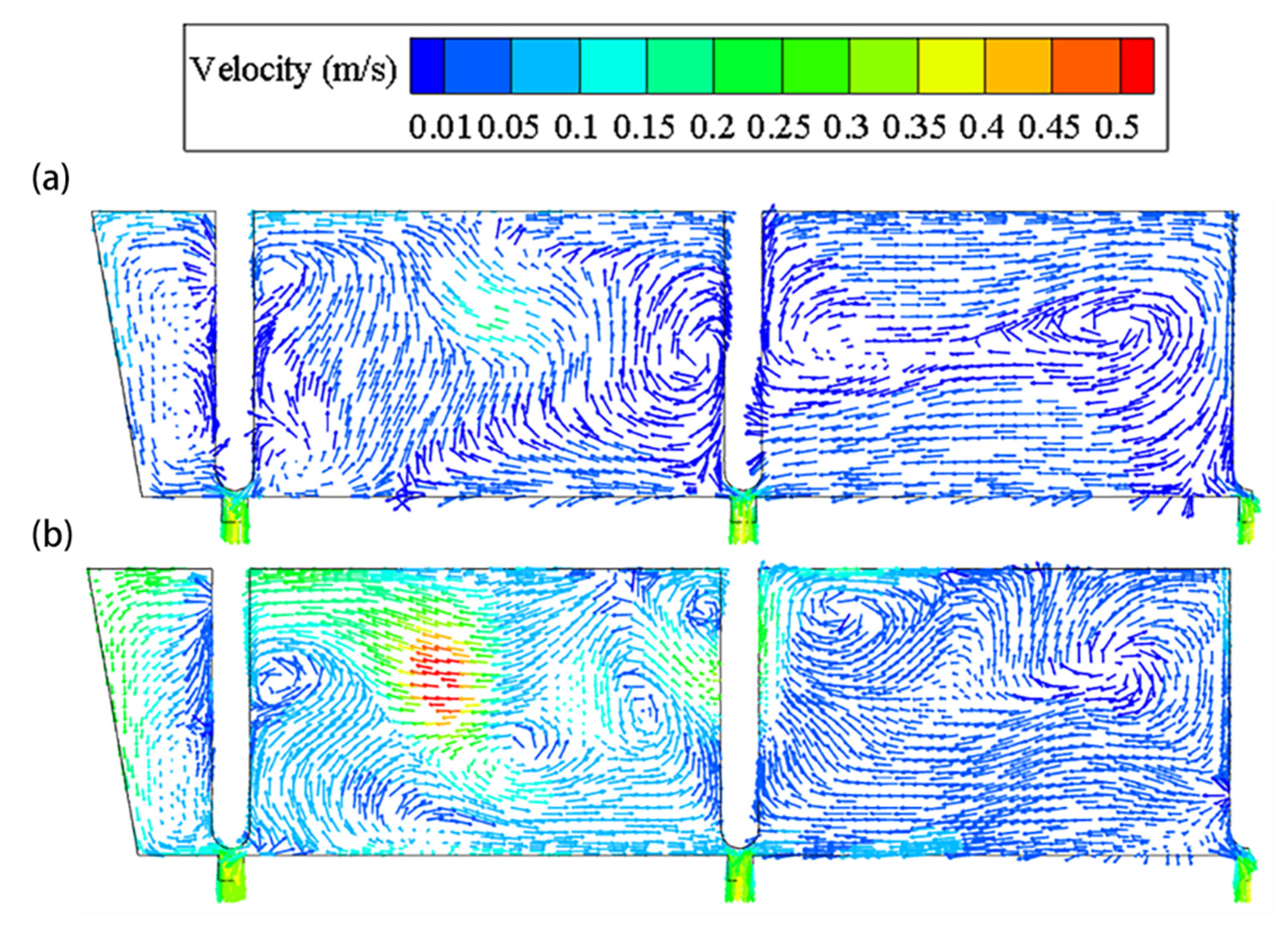
Figure 15 shows the comparison of velocity vector in the plane passing through the center of all the outlets with and without the induction heating. The velocity and flow field of molten steel are also various under different working conditions. After the induction heating is turned on, the flow velocity between the Outlet1 and Outlet2 is significantly greater than that between the Outlet2 and Outlet3, which will shorten the residence time of molten steel in the two outlets and it can be read from the RTD in Figure 13.
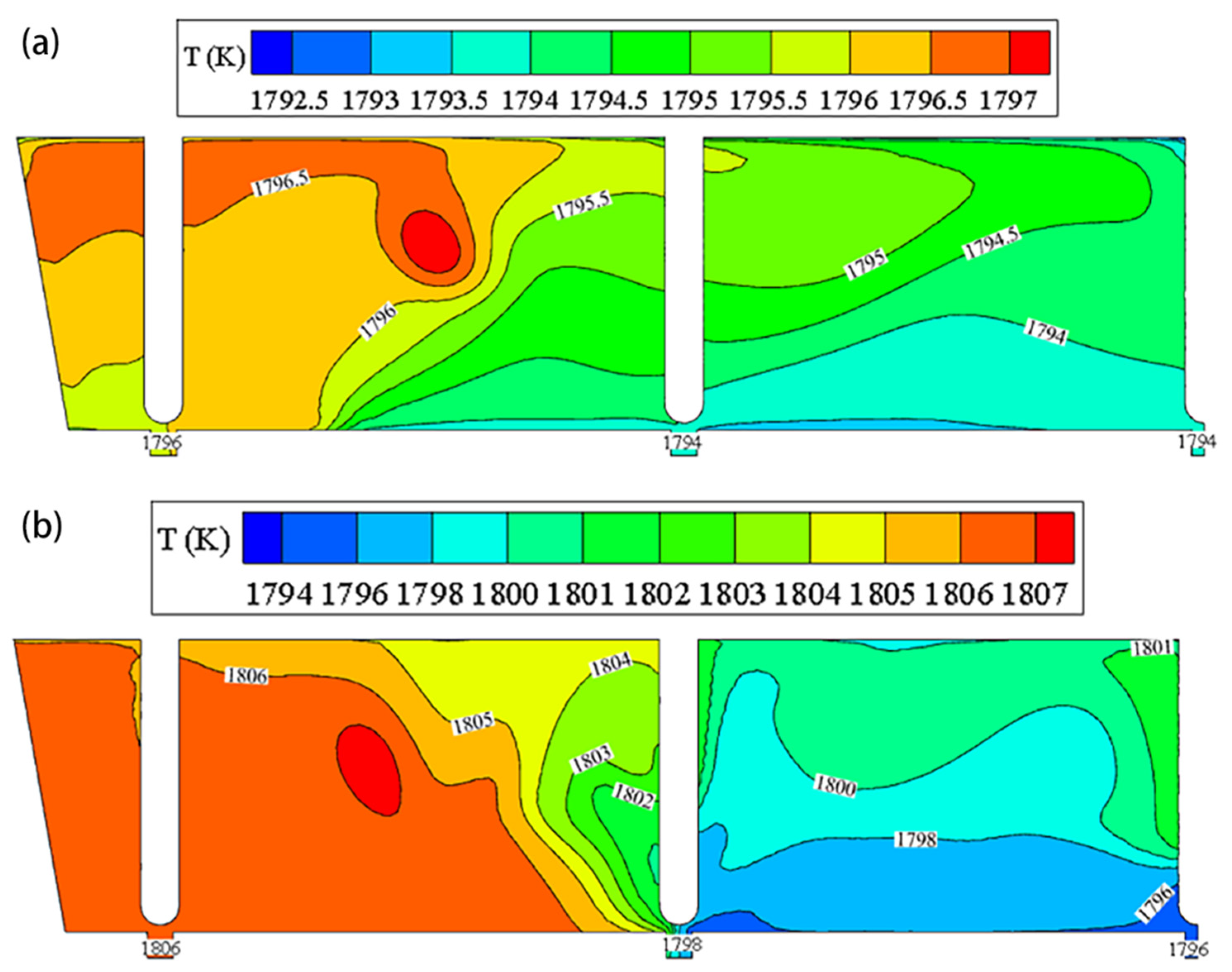
Figure 16 illustrates the comparison of temperature field in the plane passing through the center of all the outlets. When the induction heating is turned off, the temperature of the three outlets is 1796, 1794 and 1794 K, respectively, and the maximum temperature difference between them is 2 K. The stratification of temperature is obvious on the plane, but the maximum temperature difference is about 2.5 K, and the high temperature region occurs in the upper left part of the tundish because the channel exit points to the Outlet1 located in the edge region of the tundish and there is an upward flow. When the induction heating is turned on for 200 s, the temperature is obviously increased as shown in Figure 16b. The temperature near the Outlet1 is increased from 1796 to 1806 K, and the temperature of Outlet2 is increased to 1798 K. The maximum temperature difference of three outlets reaches 10 K, which is close to the measured data (7–14 K) by the steel plant. Due to the channel structural limitations, the high-temperature molten steel out of channel does not have sufficient kinetic energy to flow to the middle region and it is concentrated on the edge of the tundish. The enlargement of the temperature difference between these outlets will affect the consistency of the strand casting quality, as the different temperature means the difference in superheat degree of molten steel which will lead to the formation of varied solidification structure. Additionally, a higher superheat of casting operation has to be maintained to avoid the freezing and clogging of molten steel near Outlet3, which will restrict the induction heating function of the tundish.
From the overall analysis of the fluid flow and temperature fields given above, the induction heating by the straight channel can compensate the temperature of molten steel but may lead to a larger difference in flow velocity and temperature between strands, which will probably result in the differences in the cleanliness of molten steel and the quality of castings in the early period upon power on. For this reason, a split channel strategy is proposed in the present study to improve the overall metallurgical behavior for each strand.
3.5. Flow Field and Temperature Field of Tundish When Using Split Channel
3.5.1. Comparison of Flow Field between Three Split Channel Schemes upon Heating for 200 s at 1000 kW
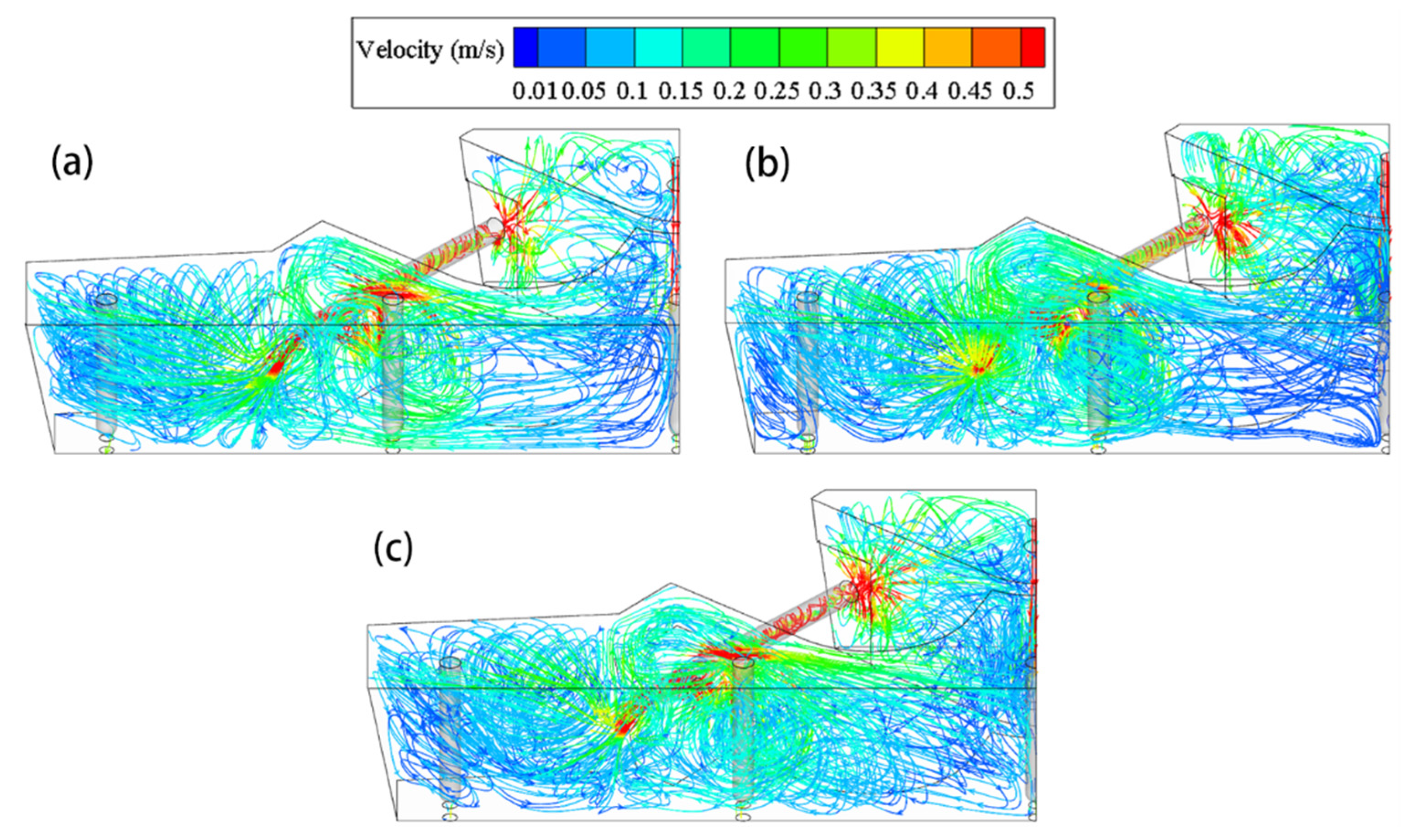
Figure 17 shows the three-dimensional streamline contour of the three bifurcated split channel cases with the angle of “Channel out2” being 0°, 5° and 15°, respectively, upon heating for 200 s, indicating that the flow of molten steel in the tundish using split channel is obviously different from that using the original straight channel. Part of the molten steel flows from the “Channel out2” to the middle region of the tundish (near the Outlet3) after being heated in the induction channel, which can activate the flow in the middle region and reduce the dead zone of the entire tundish. Meanwhile, the velocity of the molten steel in the “Channel out1” is decreased due to the diversion effect of the “Channel out2”. As a result, the short-circuit flow at the Outlet1 will be improved and the impingement of molten steel on the front wall refractory of the tundish reduced, which is beneficial to improve the cleanliness of molten steel and the service life of refractory.
Comparing the three bifurcated cases, the streamline of “Channel out2” in the case FK-A15 is higher than the other two because of bigger inclination angle, which is above the liquid level of the tundish. This phenomenon will probably result in the entrapment of cover slag into the molten steel as a source of exogenous large-size inclusions.
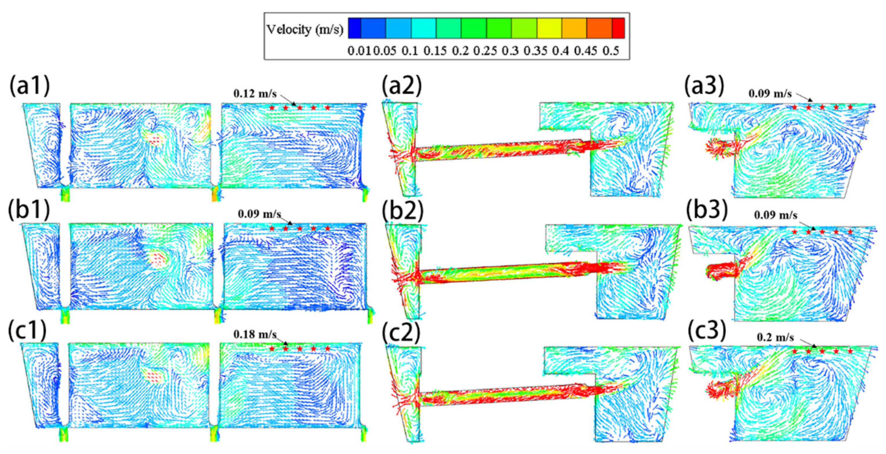
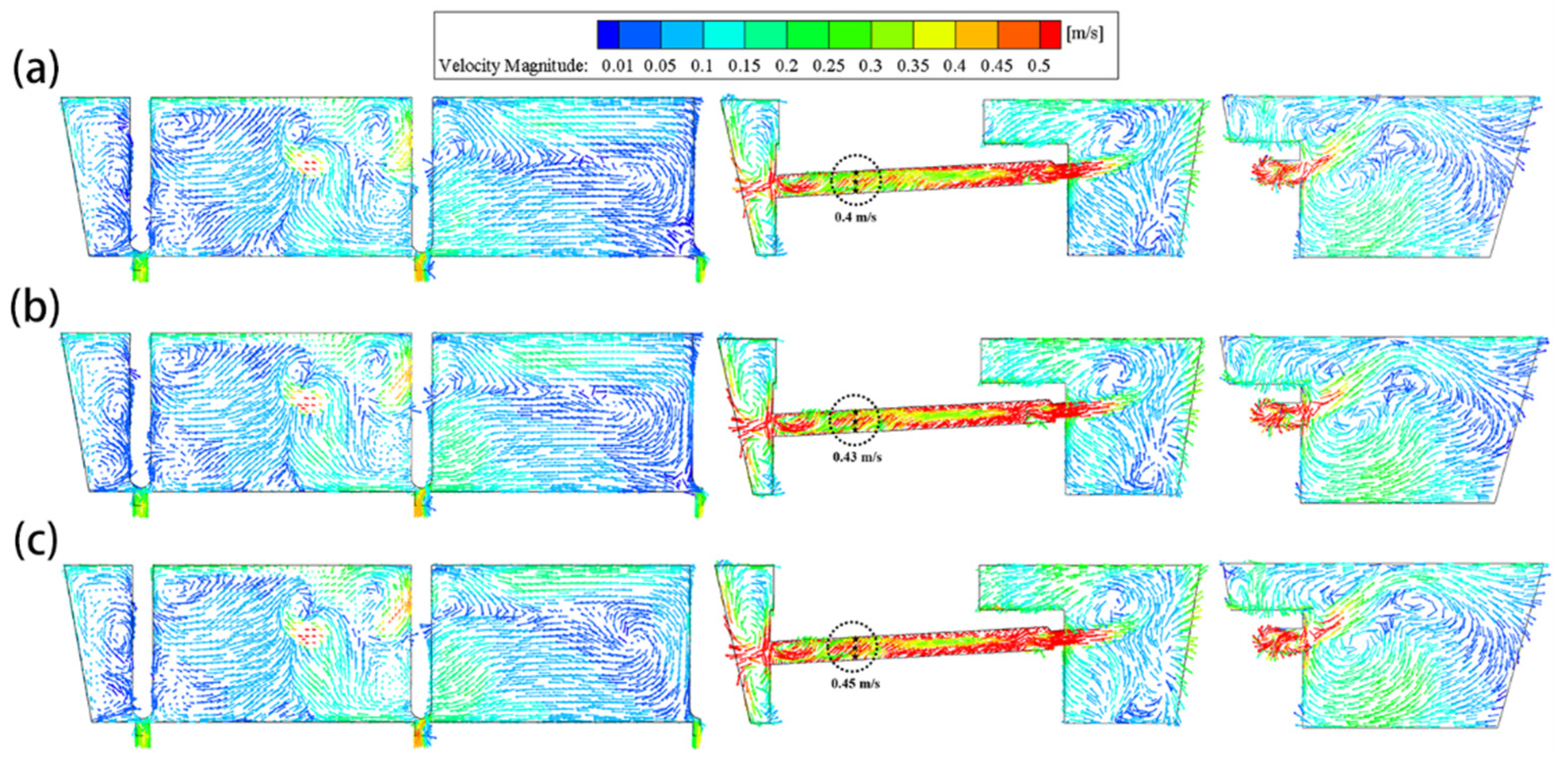
Figure 18 illustrates the velocity vector of molten steel in the plane passing through the center of all the outlets (left) and through the main channel plane (middle) and the split port (right) upon heating for 200 s at 1000 kW. The average flow velocity on the free surface is calculated from five reference points as signed in the Figure 18. Comparing Figure 15b and Figure 18, due to the split port, the flow of molten steel in the middle region of the tundish is effectively activated, and the flow velocity herein is increased, while that near the Outlet1 is reduced, thus the consistence between strands is improved. Additionally, due to the decrease in the velocity of molten steel from “Channel out1” compared with Figure 15b, its washing and erosion on the front wall of the tundish will abate accordingly. The inclination angle upwards for “Channel out2” in split channel schemes is 0°, 5° and 15°, respectively. The surface velocity between Outlet2 and Outlet3 in the case FK-A15 is larger (the average value 0.18~0.2 m/s) and the molten steel flowing out of the “Channel out2” has a tendency to impinge the free surface. Therefore, considering the uniformity of the flow field and the risk of cover slag entrapped, the case FK-A0 is believed to be optimal.
3.5.2. Comparison of Temperature Field in Split Channel Schemes upon Heating for 200 s
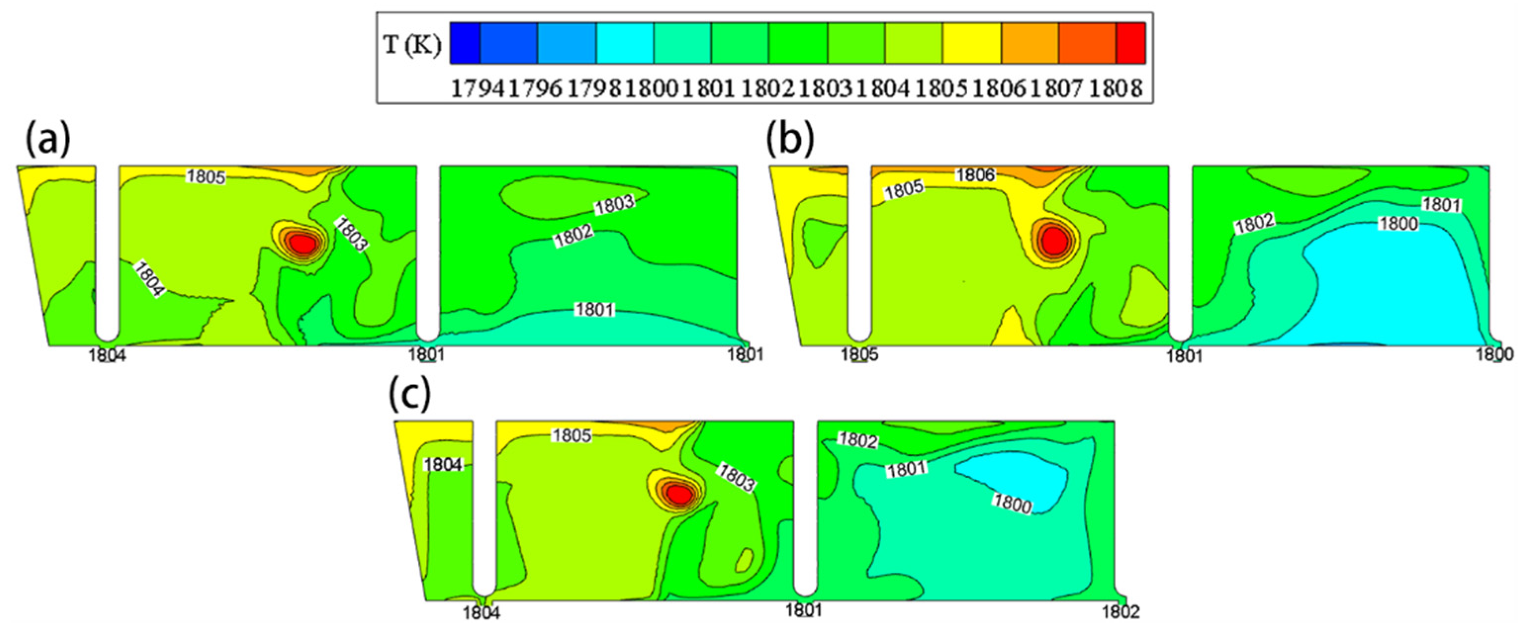
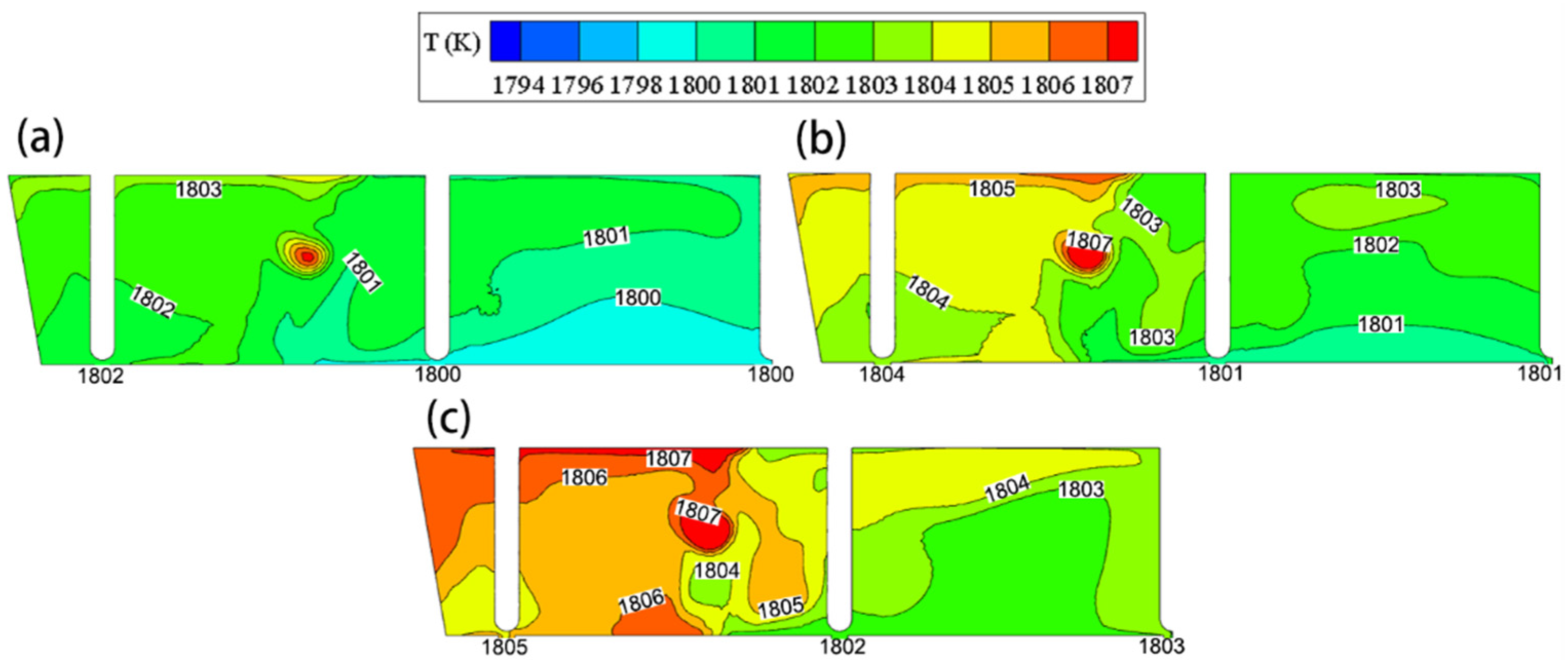
Figure 19 compares the temperature distribution of the three split channel cases in the plane passing through the tundish outlets when heating for 200 s at 1000 kW power. Except for a little high-temperature molten steel with 1807 K at “Channel out1” (see the red part), the temperature differences, whether between outlets or in the whole observed plane, are significantly lower in the split channel cases than in the S0 case as in Figure 16b, and the temperature is more homogeneously distributed from 1801 to 1806 K, except for the exit of channel. The maximum temperature difference between outlets and that in the entire plane in the FK-A0 case is only 2 and 4 K, respectively; they are 4 and 6 K in the FK-A5 case, and 3 and 5 K in the FK-A15 case. While the differences both reach 10 K in the S0 case, and the temperature is distributed between 1796 and 1806 K. Obviously, the more homogeneous the temperature distribution is, the more consistent solidification structure and casting quality between different strands will be achieved. Therefore, the split channel structure is also better than the straight channel structure from the view of temperature distribution. In addition, the difference in temperature field between three split cases can also be seen from Figure 19, which the temperature of case FK-A0 distributes generally more even due to its smaller inclination angle in “Channel out2”.
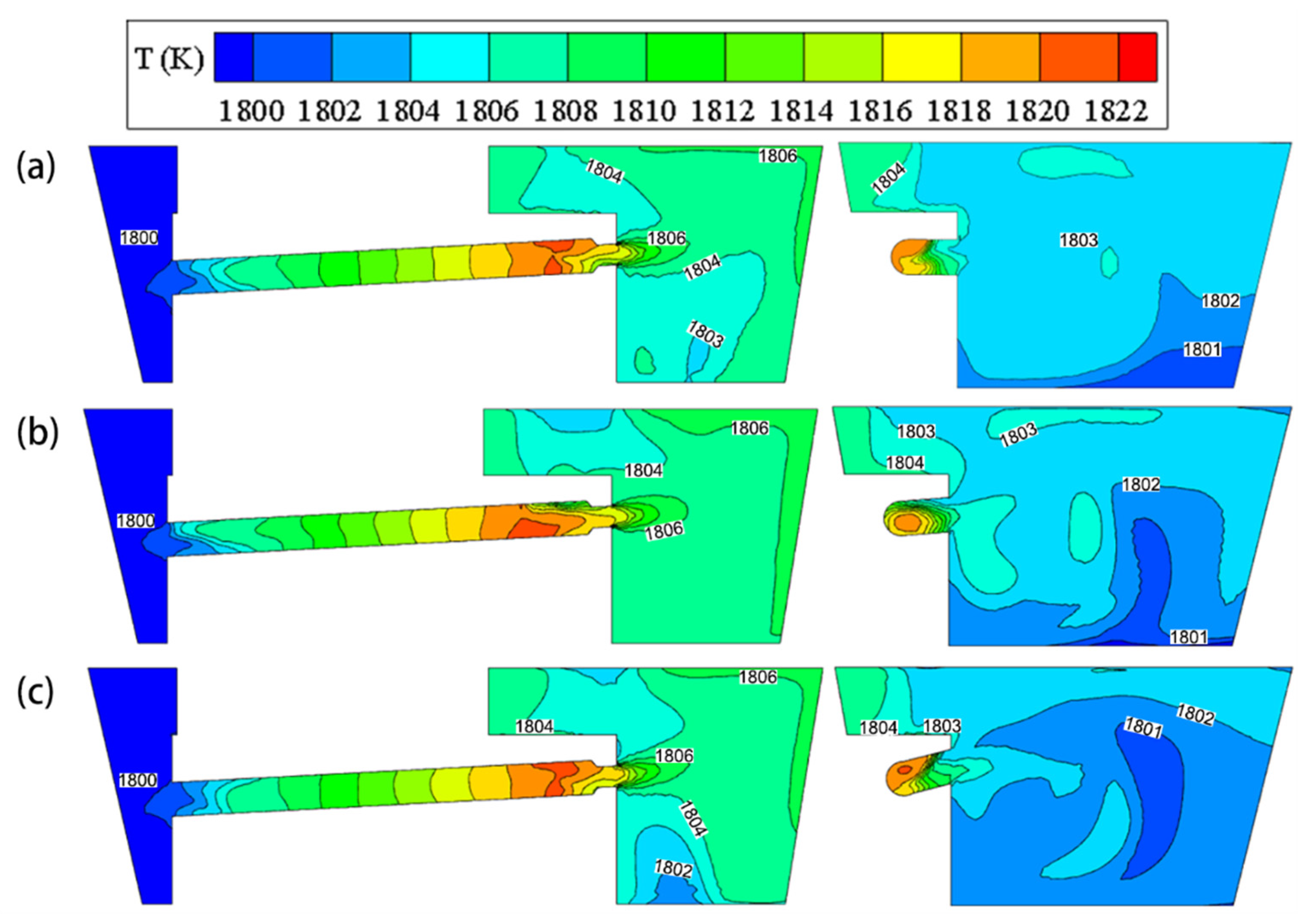
Figure 20 shows the temperature contours of split channel cases in the vertical planes passing through the main channel (left), i.e., “Channel out1” in Figure 1, and through port (right, “Channel out2”) upon heating for 200 s at 1000 kW. The temperature distributes between 1802 and 1806 K when the molten steel flows out from the main channel into the discharging chamber, which is lower than that in the S0 case shown in Figure 16b as some higher temperature of molten steel is diversified by “Channel out2”. The temperature of “Channel out2” plane distributes between 1801 and 1804 K, only a slight difference with “Channel out1” plane, and its temperature is above the S0 case, indicating the split channels are advantageous over the straight channel in the temperature homogeneity. Comparing the three split cases, the temperature distribution of the case FK-A5 is the most even in the main channel plane, while the case FK-A0 distributes most evenly in the port plane. The inclination angle of “Channel out2” in case FK-A0 is 0°. When the molten steel flows out of the “Channel out2”, part flows upwards due to thermal buoyancy, and the other flows downwards under the action of gravity, thus the distribution of molten steel is relatively even. While in the case FK-A15 with inclination angle of 15°, most high-temperature molten steel is directly transferred to the liquid level, and its part heat will be dissipated in the tundish cover slag, which should be the reason of the relatively larger low-temperature region for this case.
It can be also seen from Figure 20 that the temperature is obviously layered in the main channel. It increases from channel entrance to exit, which is in agreement with the reference study [34].
Combining the flow field with temperature field analyzed above, the split channel schemes can effectively improve the consistence of flow and temperature of molten steel in the tundish, in which the case FK-A0 is advantageous over the other two for the investigated five-strand tundish. Thus, it is chosen for the following studies. Firstly, its heating rate is compared with the case S0, then the influences of heating powers (800, 1000 and 1200 kW) on the flow of molten steel and temperature distribution are investigated.
3.6. Comparison of Heating Process between Cases FK-A0 and S0 at 1000 kW
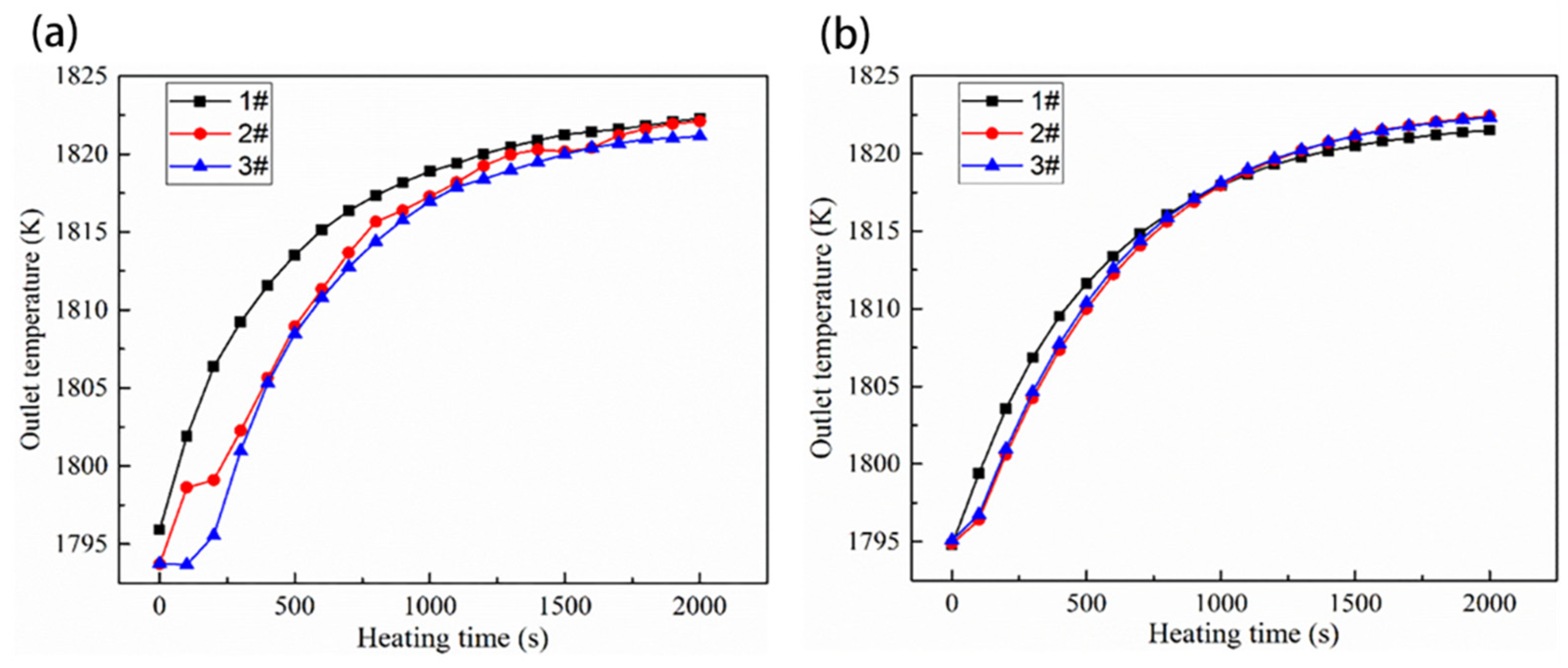
Figure 21 compares the local temperature-rising curves against heating time from Outlet1 to Outlet3 in tundish between the cases S0 and FK-A0 at 1000 kW heating power. The temperature rises quickly before 1000 s, then decays from 1000 s to 2000 s. In the initial heating stage, the temperature difference between the three outlets in the case FK-A0 is obviously smaller than that in the case S0, and there is almost no temperature difference between Outlet2 and Outlet3 for the case FK-A0 during the heating process. With the extension of heating time, the temperature difference between outlets is reduced for both FK-A0 and S0 cases. When heating for 200 s, the maximum temperature difference is 10 K for the case S0, while it is only 2 K for the case FK-A0. In the case S0, the molten steel flowing out of the channel cannot reach to the Outlet2 and Outlet3 in a short time, so the temperatures of the two outlets are lower than that of Outlet1. In the FK-A0, the molten steel flowing out of the spilt channel can reach each outlet at the close time, so their temperature difference is small. With the extension of heating time, the temperature of the molten steel in the entire tundish increases. Therefore, not only the temperature difference between the inside and outside of the channel is reduced, but also that between outlets.
As a result, the structural optimization of the induction heating tundish can improve the temperature consistency between different strands, and the effect is particularly obvious in the initial stage of heating operation.
3.7. Effect of Heating Power on Flow and Temperature Distribution for Case FK-A0
Because of a predetermined superheat required for different steel grades, the heat to be compensated in tundish is usually different. Even for the same steel grade, the required heating power is also possibly different due to the difference of actual ladle temperature. The heating power will affect the flow and temperature of molten steel in the tundish and even the inclusion removal.
Figure 22 shows the velocity vector of molten steel in the planes passing through the center of all outlets (left), the main channel (middle) and through the split port (right) for the case FK-A0 at different heating powers. The average flow velocity in a channel section is calculated from three reference points as signed in the Figure 22. From the left figure that with the increase of heating power, no obviously different flow field was observed in the tundish, except for a slightly increased high-speed area between Outlet2 and Outlet3. The high-speed area can be explained as the stronger “pinch effect” in the channel due to the increasing electromagnetic force under a relatively large heating power. The middle figure indicates that the flow velocity of molten steel in the channel slightly increases with the increasing power, from 0.4 to 0.45 m/s at the signed planes. After the molten steel flows out of the “Channel out1”, it circulates in the near region and activates the flow field near Outlet1 and Outlet2, while the molten steel between Outlet2 and Outlet3 is activated by the circulation flow from the “Channel out2”.
Figure 23 illustrates the temperature distribution of molten steel in the plane passing through the center of all outlets for the case FK-A0 under different heating powers. With the increase of heating power, the temperature of molten steel in the tundish also increases as more joule heat is generated. Both of the temperature differences across the entire plane and that between outlets are increasing. When the heating power is 800 kW, except for the small area at the exit of “Channel out1” where the temperature is slightly higher (about 1806 K), the temperature of other parts is 1800–1803 K. The temperature distribution is relatively uniform and the maximum temperature difference between outlets is 2 K. When the heating power is 1000 kW, the plane temperature is 1801–1805 K, and the maximum temperature difference between outlets is 3 K. While the heating power is increased to 1200 kW, the plane temperature reaches 1802–1807 K, and the maximum temperature difference between outlets is also 3 K. Comparing the temperature distribution under the three heating powers, high-power heating will lead to a more complicated temperature distribution and a relatively poor uniformity. In addition, high heating power will also result in a big pinch force, which probably generate discontinuous flow of molten steel during the casting process. Therefore, the power of induction heating should not be too large during operation.
Based on the above results, the appropriate heating power can be selected according to different steel grades and superheat requirements.
4. Industrial Experiments
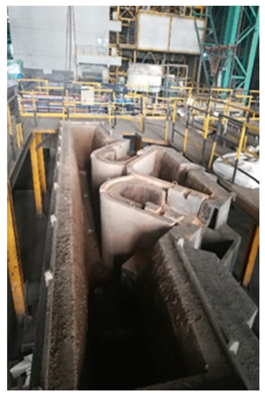
Based on the above simulation evaluation, the case FK-A0 was chosen as one of improved channel structure to upgrade the tundish metallurgical behavior. Its installation in a steel plant is shown in Figure 24.
A high carbon wire rod steel, 1070 (C 0.65–0.75%, Mn 0.60–0.90%, p < 0.040% and S < 0.050%) in ASTM standards, has been used for casting test. The local steel temperatures of the 1st and the 3rd strands were measured by thermocouples under the conditions of using the prototype straight channel case S0 and the improved bifurcated channel FK-A0. With induction heating rate of 1.5 °C/min for a constant 20 °C superheat control, the 300 mm × 390 mm bloom strand was cast under a given speed of 0.61 m/min. The temperature differences of the 1st and the 3rd strands before and after the improvement were compared in Table 5. It is seen during the casting process that the average and maximum temperature differences in the prototype straight channel tundish are 7 and 14 °C, respectively, as compared with 2.75 and 6 °C respectively by using the split channel tundish. That is to say, the use of split channel has a significant effect on improving the temperature consistence of molten steel in this tundish as revealed by numerical simulation mentioned above. With much smaller temperature difference among the outlets of tundish, the as-cast quality of the five strands will show much less difference as expected.
5. Conclusions
To make a consistent metallurgical behavior of tundish for its multi-strand castings, a novel induction heating channel has been presented and analyzed by numerical electromagnetic-heat-flow multi-physics field simulation, together with industrial casting tests. The following conclusions are drawn:
- (1)
- Induction heating can increase the temperature of molten steel and flow velocity in the tundish. However, the maximum temperature difference between the outlets is as large as 10 K when with a conventional simply straight channel structure.
- (2)
- With a novel bifurcated split channel, the induction heating tundish can effectively improve the overall flow and temperature distribution for multi-strand casting. During heating operation, the temperature difference between each outlet of the tundish is obviously dropped as compared with the situation while using conventional straight channel. The maximum temperature difference between each strand outlet in its FK-A0, FK-A5 and FK-A15 cases is 2 K, 4 K and 3 K, respectively. The case FK-A0 with its diameters of “Channel out2” at 130 mm without inclination angle upwards is advantageous over the other two cases in the flow and temperature distribution of molten steel.
- (3)
- The comparisons of temperature and fluid flow at different heating powers for the case FK-A0 suggest that the temperature increases with the increasing heating power under little changed flow field. However, an excessive heating power will lead to a relatively poor temperature uniformity in the tundish and probably a dropping flow rate in the channel due to the appearance of a large electromagnetic pinch effect. In actual production, the heating power can be chosen according to the temperature of molten steel and superheat requirement.
- (4)
- The industrial tests show that using the split case FK-A0 can decrease the average and maximum temperature differences of molten steel between strands in tundish by 4.25 and 8 °C, respectively, as compared with the conventional straight channel. The study provides a novel design idea and application case for the upgrading metallurgical effect with channel-type induction heating tundish.
Author Contributions
H.T. guided the whole study and wrote this manuscript; K.W., X.L. and J.L. performed experiments and calculations; J.Z. guided the simulation calculation and revised the manuscript. All authors have read and agreed to the published version of the manuscript.
Funding
The authors are grateful for the financial support by the National Natural Science Foundation of China [Grant No. 51874033] and Beijing Natural Science Foundation [Grant No. 2182038].
Institutional Review Board Statement
Not applicable.
Informed Consent Statement
Not applicable.
Data Availability Statement
The study did not report any data.
Acknowledgments
Thanks are given to Shagang Iron & Steel Co., Ltd. for supporting plant data.
Conflicts of Interest
The authors declare no conflict of interest.
References
- Karr, U.; Sandaiji, Y.; Tanegashima, R.; Murakami, S.; Schönbauer, B.; Fitzka, M.; Mayer, H. Inclusion initiated fracture in spring steel under axial and torsion very high cycle fatigue loading at different load ratios. Int. J. Fatigue 2020, 134, 105525. [Google Scholar] [CrossRef]
- Xu, K.D. Certain basic subjects on clean steel. Acta Metall. Sin. 2009, 45, 257–269. (In Chinese) [Google Scholar] [CrossRef]
- Zhang, C.; Jahazi, M.; Tremblay, R. Tremblay. Simulation and experimental validation of the effect of superheat on macrosegregation in large-size steel ingots. Int. J. Adv. Manuf. Technol. 2020, 107, 167–175. [Google Scholar] [CrossRef]
- Zhu, C.Y.; Wang, W.L.; Zeng, J.; Lu, C.; Zhou, L.J.; Chang, J. Interactive relationship between the superheat, interfacial heat transfer, deposited film and microstructure in strip casting of duplex stainless steel. ISIJ Int. 2019, 59, 880–888. [Google Scholar] [CrossRef] [Green Version]
- Wang, W.; Hou, Z.B.; Chang, Y.; Cao, J.H. Effect of superheat on quality of central equiaxed grain zone of continuously cast bearing steel billet based on two-dimensional segregation ratio. J. Iron Steel Res. Int. 2018, 25, 9–18. [Google Scholar] [CrossRef]
- Jiang, D.Q.; Wang, R.; Zhang, Q.; Zhang, Z.Q.; Wang, B.J.; Ren, Z.M. Experimental investigation on solidification of GCr15 bearing steel by the simulated continuous casting. Ironmak. Steelmak. 2019, 46, 801–808. [Google Scholar] [CrossRef]
- Sahai, Y. Tundish Technology for Casting Clean Steel: A Review. Metall. Mater. Trans. B 2016, 47, 2095–2106. [Google Scholar] [CrossRef]
- Ai, X.G.; Han, D.; Li, S.L.; Zeng, H.B.; Li, H.Y. Optimization of flow uniformity control device for six stream continuous casting tundish. J. Iron Steel Res. Int. 2020, 27, 1035–1044. [Google Scholar] [CrossRef]
- Yao, C.; Wang, M.; Pan, M.X.; Bao, Y.P. Optimization of large capacity six-strand tundish with flow channel for adapting situation of fewer strands casting. J. Iron Steel Res. Int. 2021. [Google Scholar] [CrossRef]
- Xiao, Z.M.; Cao, W. Technical progress in the No. 2 steelmaking plant of WISCO. Steelmaking 1996, 6, 51–55. (In Chinese) [Google Scholar]
- Filippov, G.A.; Tyuftyaev, A.S.; Gadzhiev, M.K.; Yusupov, D.I.; Sargsyan, M.A. Effect of stabilizing steel temperature in a continuous-caster tundish by the plasma method on the uniformity of the mechanical properties of plates after rolling. Metallurgist 2016, 60, 267–273. [Google Scholar] [CrossRef]
- Pan, X.L.; Wang, Y.H.; Liang, H.Z.; Feng, S.C. Independent innovative continuous casting technology of Nippon Steel in Japan. World Iron Steel 2010, 10, 31–35. (In Chinese) [Google Scholar]
- Jiang, J.; Lu, H.B.; Li, Q.Y.; Wang, B.; Li, Y.K. Application of tundish plasma heater. Contin. Cast. 2018, 43, 7–11. (In Chinese) [Google Scholar] [CrossRef]
- Mao, B.; Li, A.W.; Ma, Z.M.; Yao, H.Y.; Yi, B.; Yao, S.B. The research & development and application of tundish splayed channel induction heating and refining technology for continuous casting. Steelmaking 2015, 31, 1–6. (In Chinese) [Google Scholar]
- Zuo, X.J.; Yan, J.W.; Luo, L.H.; Han, Z.W. Application of plasma tundish heating technology in continuous casting process. Iron Steel Technol. 2016, 1, 10–18. (In Chinese) [Google Scholar]
- Ilegbusi, O.J.; Szekely, J. Effect of magnetic field on flow, temperature and inclusion removal in shallow tundishes. ISIJ Int. 1989, 29, 1031–1039. [Google Scholar] [CrossRef]
- Zhang, G.Q.; Jin, S.T. Mathermatical simulation of flow field in channel-tundish by induction heating. J. North China Univ. Technol. 1998, 10, 36–42. (In Chinese) [Google Scholar]
- Mao, B.; Tao, J.M.; Jiang, T.X. Tundish channel type induction heating technology for continuous casting. Contin. Cast. 2008, 5, 4–8. (In Chinese) [Google Scholar] [CrossRef]
- Ueda, T.; Ohara, A.; Sakurai, M.; Yoshii, Y. A Tundish Provided with a Heating Device for Molten Steel. European Patent EP0119853, 16 March 1984. [Google Scholar]
- Xing, F.; Zheng, S.G.; Zhu, M.Y. Motion and removal of inclusions in new induction heating tundish. Steel Res. Int. 2018, 89, 1700542. [Google Scholar] [CrossRef]
- Yue, Q.; Pei, X.; Zhang, C.; Wang, X. Magnetohydrodynamic calculation on double-loop channel induction tundish. Arch. Metall. Mater. 2018, 63, 329–336. [Google Scholar] [CrossRef]
- Yang, B.; Lei, H.; Bi, Q.; Jiang, J.M.; Zhang, H.W.; Zhao, Y.; Zhou, J.A. Electromagnetic conditions in a tundish with channel type induction heating. Steel Res. Int. 2018, 89, 1800145. [Google Scholar] [CrossRef]
- Wang, Q.; Qi, F.S.; Li, B.K.; Tsukihashi, F. Behavior of non-metallic inclusions in a continuous casting tundish with channel type induction heating. ISIJ Int. 2014, 54, 2796–2805. [Google Scholar] [CrossRef] [Green Version]
- Yang, B.; Deng, A.Y.; Wang, E.G. Simulating the magnetic field/transfer phenomenon of the tundish with channel type inducting heating. IOP Conf. Ser. Mater. Sci. Eng. 2018, 424, 012060. [Google Scholar] [CrossRef] [Green Version]
- Xing, F.; Zheng, S.G.; Zhu, M.Y. Numerical simulation of effect of channel tilt angle on induction heating tundish. Steelmaking 2019, 35, 27–33. (In Chinese) [Google Scholar]
- Delgado, O.S.; Torres-Alonso, E.; Ramos, J.A.; Arreola, S.A.; Hernández, C.A.; Téllez, J.S. Thermal and fluid-dynamic optimization of a five strand asymmetric delta shaped billet caster tundish. Steel Res. Int. 2018, 89, 1700428. [Google Scholar] [CrossRef]
- Morales, R.D.; López-Ramirez, S.; Palafox-Ramos, J.; Zacharia, D. Numerical and modeling analysis of fluid flow and heat transfer of liquid steel in a tundish with different flow control devices. ISIJ Int. 1999, 39, 455–462. [Google Scholar] [CrossRef] [Green Version]
- Wu, G.H.; Tang, H.Y.; Xiao, H.; Yao, H.Y.; Zhang, J.Q. Physical simulation on a 7-strand continuous casting tundish with channel type induction heating. Iron Steel 2017, 52, 20–26. (In Chinese) [Google Scholar] [CrossRef]
- Tang, H.Y.; Li, X.S.; Zhang, S.; Zhang, J.Q. Fluid flow and heat transfer in a tundish with channel induction heating for sequence casting with a constant superheat control. Acta. Metall. Sin. 2020, 56, 1629–1642. (In Chinese) [Google Scholar] [CrossRef]
- Dou, W.X.; Yao, H.Y.; Chang, L.S.; Xie, L. Physical simulation of flow field for channel induction heating tundish. Contin. Cast. 2019, 44, 29–33. (In Chinese) [Google Scholar] [CrossRef]
- Zhang, S.; Tang, H.Y.; Liu, J.W.; Xiao, H.; Yao, H.Y.; Zhang, J.Q. Structural optimization of a six-strand H-type channel induction heating tundish. J. Iron Steel Res. Int. 2019, 31, 787–794. [Google Scholar] [CrossRef]
- Yang, B.; Lei, H.; Bi, Q.; Jiang, J.M.; Zhang, H.W.; Zhao, Y.; Zhou, J.A. Fluid flow and heat transfer in a tundish with channel type induction heating. Steel Res. Int. 2018, 89, 1800173. [Google Scholar] [CrossRef]
- Ma, Y.L.; Liu, J.F.; Xing, S.Q.; Chen, C.Y.; Sun, B.B.; Wang, T. Numerical simulation of continuous casting tundish channel type electromagnetic induction heating. Contin. Cast. 2016, 41, 50–53. (In Chinese) [Google Scholar] [CrossRef]
- Yue, Q.; Zhang, C.B.; Pei, X.H. Magnetohydrodynamic flows and heat transfer in a twin-channel induction heating tundish. Ironmak. Steelmak. 2017, 44, 227–236. [Google Scholar] [CrossRef]
- Launder, B.E.; Spalding, D.B. The numerical computation of turbulent flows. Comput. Methods Appl. Mech. Eng. 1974, 3, 269–289. [Google Scholar] [CrossRef]
- Vives, C.; Ricou, R. Magnetohydrodynamic flows in a channel-induction furnace. Metall. Mater. Trans. B 1991, 22, 193–209. [Google Scholar] [CrossRef]
- Tang, H.Y.; Guo, L.Z.; Wu, G.H.; Xiao, H.; Yao, H.Y.; Zhang, J.Q. Hydrodynamic modeling and mathematical simulation on flow field and inclusion removal in a seven-strand continuous casting tundish with channel type induction heating. Metals 2018, 8, 374. [Google Scholar] [CrossRef] [Green Version]
Figure 1.
Geometric models of the tundish with different channel modes: (a) S0; (b) FK.

Figure 2.
Schematics of the model in grids: (a) Case S0; (b) Case FK-A0.

Figure 3.
Schematics of the sections for numerical analysis: (a) Case S0; (b) Case FK-A0.

Figure 4.
Multi-physics coupling calculation process for the induction heating tundish. MHD: magnetic induction equation.
Figure 4.
Multi-physics coupling calculation process for the induction heating tundish. MHD: magnetic induction equation.

Figure 5.
Location of the reference point: (a) channel exit section for S0 case; (b) “Channel out1” section for FK-A0 case.
Figure 5.
Location of the reference point: (a) channel exit section for S0 case; (b) “Channel out1” section for FK-A0 case.

Figure 6.
Comparison of RTD (residence time distribution) curves for case FK-A0: (a) hydrodynamic modeling experiment; (b) mathematical simulation.
Figure 6.
Comparison of RTD (residence time distribution) curves for case FK-A0: (a) hydrodynamic modeling experiment; (b) mathematical simulation.

Figure 7.
Numerical simulation and reference measurement results of magnetic field distribution on Z = −20 cm channel section: (a) left channel; (b) middle channel. Reprinted with permission from ref. [36]. Copyright 1991 Springer Nature.
Figure 7.
Numerical simulation and reference measurement results of magnetic field distribution on Z = −20 cm channel section: (a) left channel; (b) middle channel. Reprinted with permission from ref. [36]. Copyright 1991 Springer Nature.

Figure 8.
Comparison of magnetic induction intensity in Y direction between calculated and measured values: (a) left channel; (b) middle channel.
Figure 8.
Comparison of magnetic induction intensity in Y direction between calculated and measured values: (a) left channel; (b) middle channel.

Figure 9.
Magnetic field intensity distribution in tundish.

Figure 10.
Vector contour in channel cross section: (a) magnetic field; (b) electromagnetic force.

Figure 11.
Joule heat distribution in tundish.

Figure 12.
Three-dimensional (3D) streamline comparison of case S0: (a) without induction heating; (b) with induction heating.
Figure 12.
Three-dimensional (3D) streamline comparison of case S0: (a) without induction heating; (b) with induction heating.

Figure 13.
Comparison of RTD (residence time distribution) curves of case S0: (a) without induction heating; (b) with induction heating.
Figure 13.
Comparison of RTD (residence time distribution) curves of case S0: (a) without induction heating; (b) with induction heating.

Figure 14.
Velocity vector in channel longitudinal section for case S0: (a) without induction heating; (b) with heating for 200 s at 1000 kW.
Figure 14.
Velocity vector in channel longitudinal section for case S0: (a) without induction heating; (b) with heating for 200 s at 1000 kW.

Figure 15.
Velocity vector at vertical plane passing through all outlet centers of case S0: (a) without induction heating; (b) with heating for 200 s at 1000 kW.
Figure 15.
Velocity vector at vertical plane passing through all outlet centers of case S0: (a) without induction heating; (b) with heating for 200 s at 1000 kW.

Figure 16.
Temperature field at the plane passing through all outlet centers for case S0: (a) without induction heating; (b) with heating for 200 s at 1000 kW.
Figure 16.
Temperature field at the plane passing through all outlet centers for case S0: (a) without induction heating; (b) with heating for 200 s at 1000 kW.

Figure 17.
Three-dimensional (3D) streamline contour of three split channel schemes: (a) FK-A0; (b) FK-A5; (c) FK-A15.
Figure 17.
Three-dimensional (3D) streamline contour of three split channel schemes: (a) FK-A0; (b) FK-A5; (c) FK-A15.

Figure 18.
Velocity vectors of split channel schemes in the planes passing through the center of all outlets (left), “Channel out1” (middle) and split port (right): (a1–a3) FK-A0; (b1–b3) FK-A5; (c1–c3) FK-A15.
Figure 18.
Velocity vectors of split channel schemes in the planes passing through the center of all outlets (left), “Channel out1” (middle) and split port (right): (a1–a3) FK-A0; (b1–b3) FK-A5; (c1–c3) FK-A15.

Figure 19.
Temperature field in the plane passing through outlet center for different cases: (a) FK-A0; (b) FK-A5; (c) FK-A15.
Figure 19.
Temperature field in the plane passing through outlet center for different cases: (a) FK-A0; (b) FK-A5; (c) FK-A15.

Figure 20.
Temperature field in the longitudinal planes of main channel (left) and port (right) for split schemes: (a) FK-A0; (b) FK-A5; (c) FK-A15.
Figure 20.
Temperature field in the longitudinal planes of main channel (left) and port (right) for split schemes: (a) FK-A0; (b) FK-A5; (c) FK-A15.

Figure 21.
Temperature rising curve of tundish outlets against heating time: (a) S0; (b) FK-A0.

Figure 22.
Velocity vector in the vertical planes passing through the center of all outlets (left), main channel (middle) and port (right) for case FK-A0 under different heating power: (a) 800 kW; (b) 1000 kW; (c) 1200 kW.
Figure 22.
Velocity vector in the vertical planes passing through the center of all outlets (left), main channel (middle) and port (right) for case FK-A0 under different heating power: (a) 800 kW; (b) 1000 kW; (c) 1200 kW.

Figure 23.
Temperature field of the plane passing through all outlet center for case FK-A0 under different heating power: (a) 800 kW; (b) 1000 kW; (c) 1200 kW.
Figure 23.
Temperature field of the plane passing through all outlet center for case FK-A0 under different heating power: (a) 800 kW; (b) 1000 kW; (c) 1200 kW.

Figure 24.
Improved tundish structure picture.


Table 1.
Geometrical sizes of the tundish with induction heating channel.
| Parameter | Value |
|---|---|
| Tundish capacity (t) | 40 |
| Molten steel depth (mm) | 900 |
| Inner diameter, submerged depth of long nozzle (mm) | 95,300 |
| Inner diameter of submerged entry nozzle (mm) | 80 |
| Induction channel diameter of S0 case (mm) | 130 |
| Induction channel length of S0 case (mm) | 1400 |
| Main channel length of FK cases (mm) | 1700 |
| Channel out1, out2 diameters (mm) | 80,130 |
| Height from channel center to tundish bottom (mm) | 472 |
Table 2.
Plan chart for numerical analysis.
| Case | Inclination Angle Upwards of Channel out2 | Flow Field and Temperature Field without Induction Heating | Flow Field and Temperature Field with Induction Heating at 1000 kW for 200 s | Flow Field and Temperature Field with Different Heating Power |
|---|---|---|---|---|
| S0 | \ | √ | √ | × |
| FK-A0 | 0° | × | √ | √ |
| FK-A5 | 5° | × | √ | × |
| FK-A15 | 15° | × | √ | × |
| Parameter | Value |
|---|---|
| Current frequency (Hz) | 50 |
| Relative permeability of iron core | 1000 |
| Induction coil conductivity (S·m−1) | 3.18 × 10⁷ |
| Relative permeability of induction coil | 1 |
| Relative permeability of air domain | 1 |
| Conductivity of molten steel (S·m−1) | 7.14 × 10⁵ |
| Relative permeability of molten steel | 1 |
| Inlet molten steel temperature (K) | 1800 |
| Density of molten steel (kg·m−3) | 8523−0.8358 T |
| Dynamic viscosity of molten steel (Pa·s) | 0.0061 |
| Thermal conductivity of molten steel (W·m−1·K−1) | 41 |
| Specific heat capacity of molten steel (J·kg−1·K−1) | 750 |
| Surface heat flux (W·m−2) | 15,000 |
| Bottom heat flux (W·m−2) | 1800 |
| Long wall heat flux (W·m−2) | 4600 |
| Short wall heat flux (W·m−2) | 4000 |
| Channel heat flux (W·m−2) | 1200 |
Table 4.
Temperature of reference points with different grid numbers.
| Case | Grids Number | T1/K | T2/K | T3/K |
|---|---|---|---|---|
| S0 | 606,244 | 1800.47 | 1799.51 | 1797.18 |
| 779,156 | 1801.12 | 1799.15 | 1796.81 | |
| 3,718,389 | 1801.25 | 1797.78 | 1796.01 | |
| FK-A0 | 487,767 | 1800.84 | 1800.62 | 1799.55 |
| 808,426 | 1801.02 | 1800.73 | 1799.91 | |
| 3,096,045 | 1801.17 | 1800.75 | 1799.49 |
Table 5.
Comparison of temperature difference between 1st and 3rd strands in two channels.
| Measuring Times (n) | 1 | 2 | 3 | 4 | 5 | 6 | 7 | 8 | (°C) | |
|---|---|---|---|---|---|---|---|---|---|---|
| (°C) | ||||||||||
| Straight channel | 6 | 1 | 6 | 3 | 8 | 9 | 14 | 9 | 7.0 | |
| Split channel | 2 | 3 | 3 | 0 | 6 | 2 | 0 | 6 | 2.75 | |
Publisher’s Note: MDPI stays neutral with regard to jurisdictional claims in published maps and institutional affiliations. |
© 2021 by the authors. Licensee MDPI, Basel, Switzerland. This article is an open access article distributed under the terms and conditions of the Creative Commons Attribution (CC BY) license (https://creativecommons.org/licenses/by/4.0/).
Share and Cite
MDPI and ACS Style
Tang, H.; Wang, K.; Li, X.; Liu, J.; Zhang, J. Improved Metallurgical Effect of Tundish through a Novel Induction Heating Channel for Multistrand Casting. Metals 2021, 11, 1075. https://doi.org/10.3390/met11071075
AMA Style
Tang H, Wang K, Li X, Liu J, Zhang J. Improved Metallurgical Effect of Tundish through a Novel Induction Heating Channel for Multistrand Casting. Metals. 2021; 11(7):1075. https://doi.org/10.3390/met11071075
Chicago/Turabian StyleTang, Haiyan, Kaimin Wang, Xiaosong Li, Jinwen Liu, and Jiaquan Zhang. 2021. "Improved Metallurgical Effect of Tundish through a Novel Induction Heating Channel for Multistrand Casting" Metals 11, no. 7: 1075. https://doi.org/10.3390/met11071075
Note that from the first issue of 2016, this journal uses article numbers instead of page numbers. See further details here.