
The Process Design and Rapid Superplastic Forming of Industrial AA5083 for a Fender with a Negative Angle in a Small Batch


Abstract
:1. Introduction
2. Experimental
3. Results and Discussion
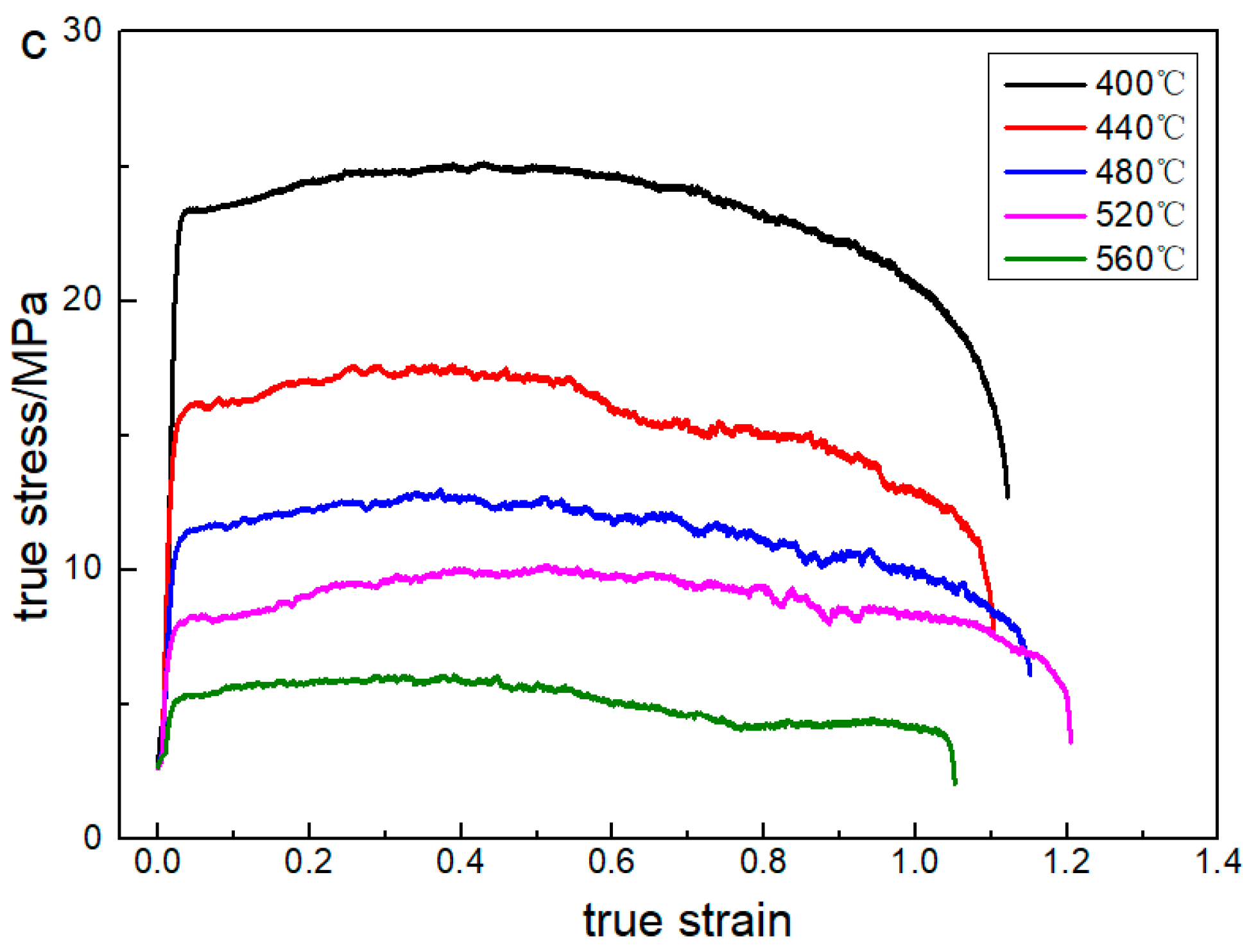
3.1. Flow Stress of AA5083 at Elevated Temperatures
3.2. Structural Design and Process Optimization
3.2.1. Initial Design
- (1)
- Drawing of the preforming process
- (2)
- Reverse superplastic bulging of the preforming process
- (3)
- Drawing of the final forming process
- (4)
- Superplastic bulging of the final forming process
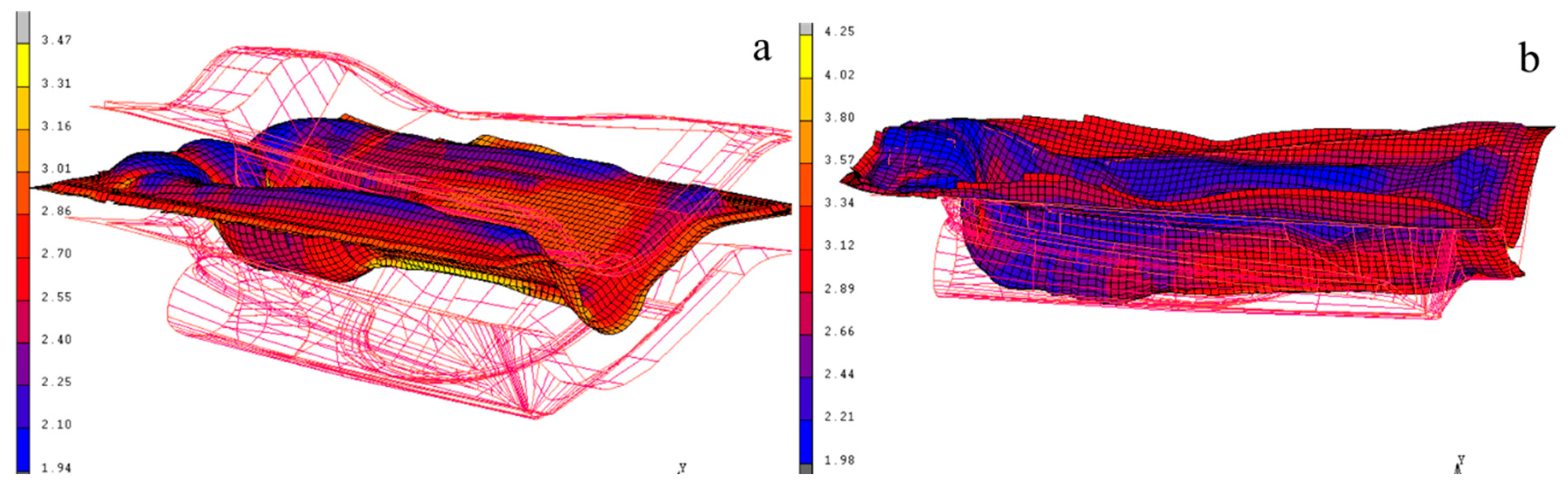
3.2.2. Optimized Design
- (1)
- Drawing of the preforming process
- (2)
- Reverse bulging of the preforming process
- (3)
- Drawing of the final forming process
- (4)
- SPF of the final forming process
3.3. Rapid SPF of the Front Fender
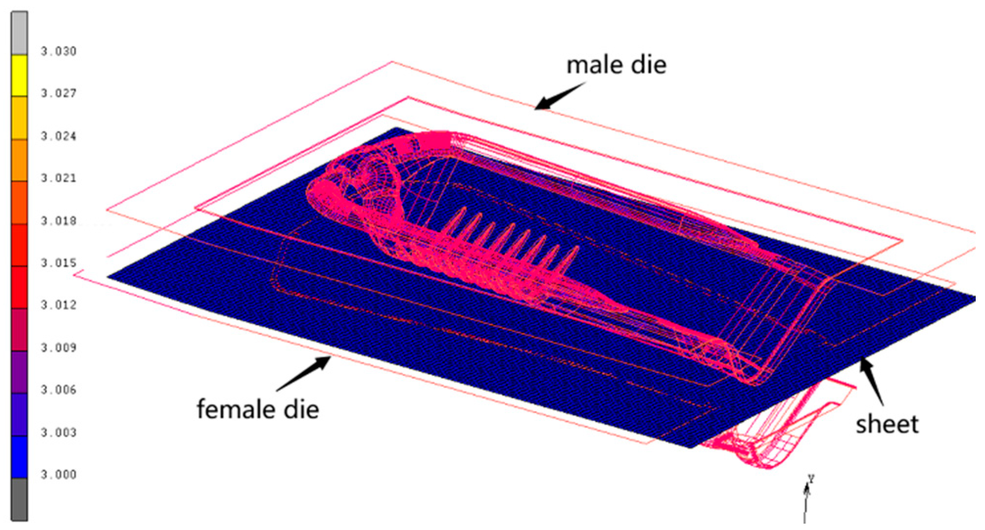
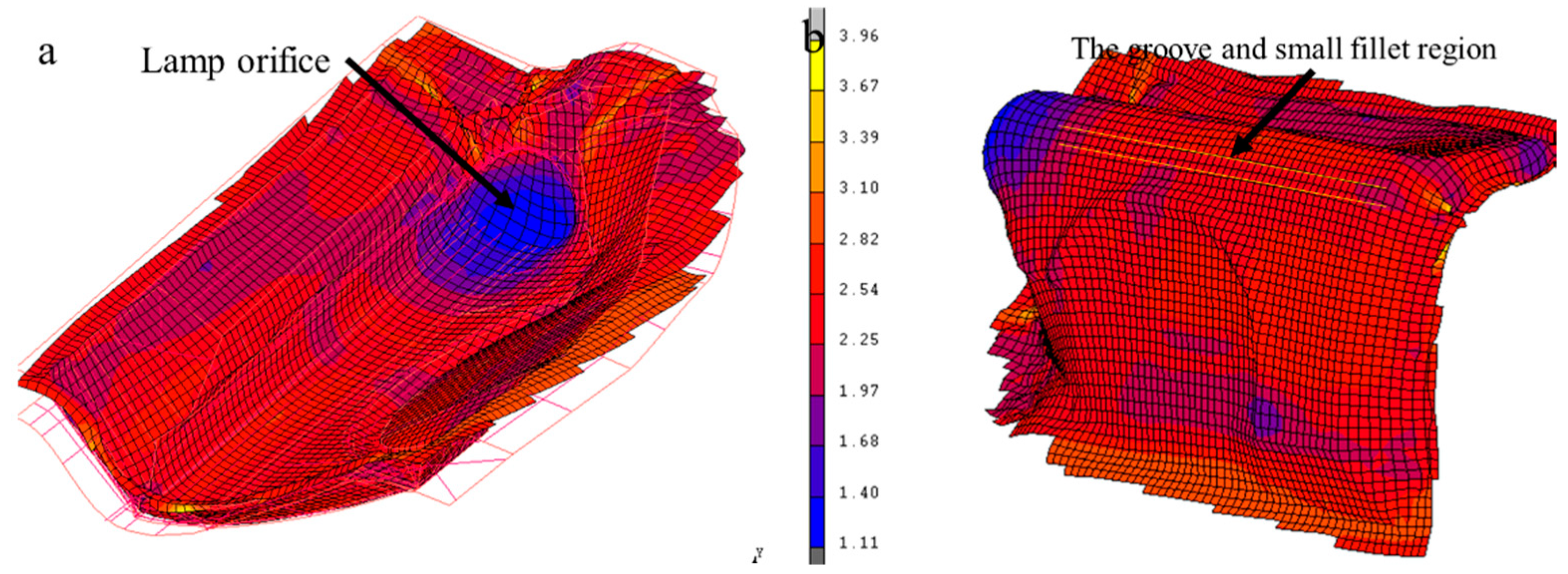
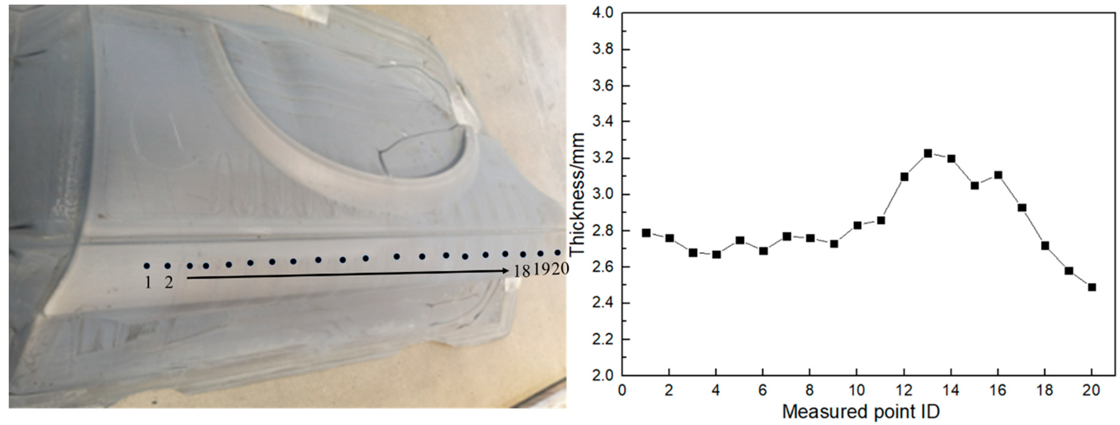
3.3.1. Thickness Distribution
- (1)
- Preforming process
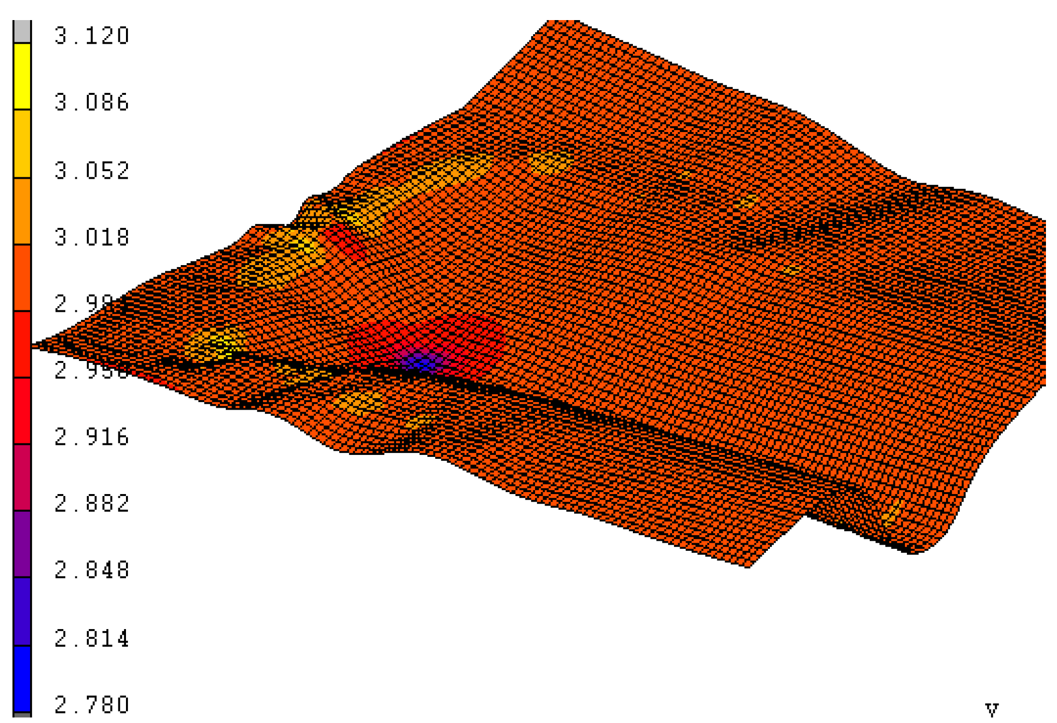
- (2)
- Final forming process
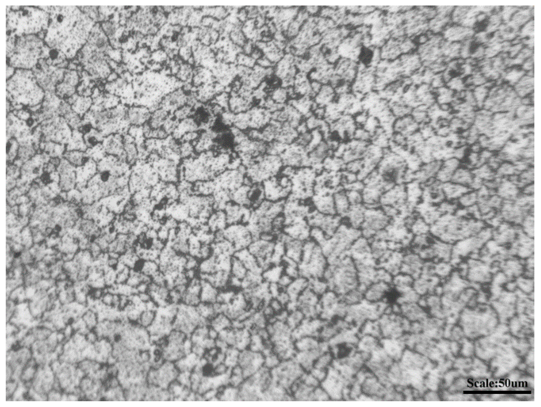
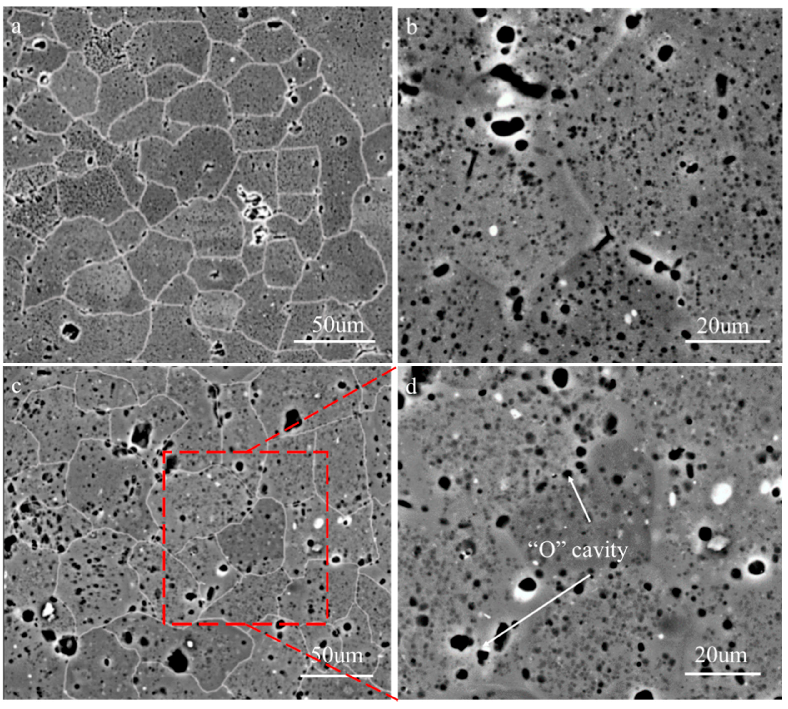
3.3.2. Macro/Micro Performance of the Postmaterial
4. Conclusions
Author Contributions
Funding
Institutional Review Board Statement
Informed Consent Statement
Data Availability Statement
Acknowledgments
Conflicts of Interest
References
- Ma, M.Y.; Wang, B.; Liu, H.Q.; Yi, D.Q.; Shen, F.H.; Zhai, T.G. Investigation of fatigue crack propagation behavior of 5083 aluminum alloy under various stress ratios: Role of grain boundary and schmid factor. Mater. Sci. Eng. A 2020, 773, 138871. [Google Scholar] [CrossRef]
- Holroyd, N.J.H.; Burnett, T.L.; Seifi, M.; Lewandowski, J.J. Improved understanding of environment-induced cracking (EIC) of sensitized 5XXX series aluminum alloys. Mater. Sci. Eng. A 2017, 682, 613–621. [Google Scholar] [CrossRef]
- Magee, A.C.; Ladani, L. Representation of a microstructure with bimodal grain size distribution through crystal plasticity and cohesive interface modeling. Mech. Mater. 2015, 82, 1–12. [Google Scholar] [CrossRef]
- Magee, A.; Ladani, L.; Topping, T.D.; Lavernia, E.J. Effects of tensile test parameters on the mechanical properties of a bimodal Al-Mg alloy. Acta Mater. 2012, 60, 5838–5849. [Google Scholar] [CrossRef]
- Jin, H. Optimization of aluminum alloy AA5083 for superplastic and quick plastic forming. Metall. Mater. Trans. A 2019, 50, 3868–3890. [Google Scholar] [CrossRef]
- Giuliano, G.; Samani, F. Comparison between superplastic and non-superplastic grade AA 5083. J. Test. Eval. 2016, 44, 2114–2119. [Google Scholar] [CrossRef]
- Krajewski, P.E.; Schroth, J.G. Overview of quick plastic forming technology. Mater. Sci. Forum 2007, 551, 3–12. [Google Scholar] [CrossRef]
- Liu, J.; Tan, M.J.; Lim, C.V.S.; Chua, B.W. Process optimization and microstructural development during superplastic-like forming of AA5083. Int. J. Adv. Manuf. Technol. 2013, 69, 2415–2422. [Google Scholar] [CrossRef]
- Liu, J.; Tan, M.J.; Aue-u-lan, Y.; Jarfors, A.E.W.; Fong, K.S.; Castagne, S. Superplastic-like forming of non-superplastic AA5083 combined with mechanical pre-forming. Int. J. Adv. Manuf. Technol. 2011, 52, 123–129. [Google Scholar] [CrossRef]
- Barnes, A.J.; Raman, H.; Lowerson, A.; Edwards, D. Recent application of superformed 5083 aluminum alloy in the aerospace industry. Mater. Sci. Forum 2012, 735, 361–371. [Google Scholar] [CrossRef]
- Hefti, L.D. Co mmercial airplane applications of superplastically formed AA5083 aluminum sheet. J. Mater. Eng. Perform. 2007, 16, 136–141. [Google Scholar] [CrossRef]
- Park, H.S.; Dang, X.P.; Roderburg, A.; Nau, B. Development of plastic front side panels for green cars. CIRP J. Manuf. Sci. Technol. 2013, 6, 44–52. [Google Scholar] [CrossRef]
- Tao, W.; Liu, Z.; Zhu, P.; Zhu, C.; Chen, W. Multi-scale design of three dimensional woven composite automobile fender using modified particle swarm optimization algorithm. Compos. Struct. 2017, 181, 73–83. [Google Scholar] [CrossRef]
- Hu, W.; Yao, L.G.; Hua, Z.Z. Optimization of sheet metal forming processes by adaptive response surface based on intelligent sampling method. J. Mater. Process. Technol. 2008, 197, 77–88. [Google Scholar] [CrossRef]
- Fan, Z.J.; Gui, L.J.; Su, R.Y. Research and development of automotive lightweight technology. J. Automo. Saf. Energy 2014, 5, 1–16. [Google Scholar]
- Park, H.S.; Nguyen, T.T. Optimization of injection molding process for car fender in consideration of energy efficiency and product quality. J. Comput. Des. Eng. 2014, 1, 256–265. [Google Scholar] [CrossRef] [Green Version]
- Roth, R.; Clark, J.; Kelkar, A. Automobile bodies: Can aluminum be an economical alternative to steel? JOM 2001, 53, 28–32. [Google Scholar] [CrossRef]
- Zhang, K.F.; Jiang, S.S. Superplastic forming. In Comprehensive Materials Processing, 1st ed.; Hashmi, S., Batalha, G.F., van Tyne, C.J., Yilbas, B., McGeough, J., Eds.; Elsevier: Amsterdam, The Netherlands, 2014; Volume 5, pp. 371–392. [Google Scholar]
- Jafar, R.A.; Jarrar, F.S.; Al-Huniti, N.S. Two-stage approach for improving the thickness distribution in superplastic forming. J. Mater. Sci. Res. 2015, 4, 12–27. [Google Scholar] [CrossRef]
- Jarrar, F.S.; Liewald, M.; Schmid, P.; Fortanier, A. Superplastic forming of triangular channels with sharp radii. J. Mater. Eng. Perform. 2014, 23, 1313–1320. [Google Scholar] [CrossRef]
- Zhang, K.F.; Wang, G.F.; Wu, D.Z.; Wang, Z.R. Research on the controlling of the thickness distribution in superplastic forming. J. Mater. Process. Technol. 2004, 151, 54–57. [Google Scholar] [CrossRef]
- Xing, H.L.; Zhang, K.F.; Wang, Z.R. A preform design method for sheet superplastic bulging with finite element modeling. J. Mater. Process. Technol. 2004, 151, 284–288. [Google Scholar] [CrossRef]
- Jarrar, F.S.; Jr, L.G.H.; Khraisheh, M.K.; Bower, A.F. New approach to gas pressure profile prediction for high temperature AA5083 sheet forming. J. Mater. Process. Technol. 2010, 210, 825–834. [Google Scholar] [CrossRef]
- Lan, H.C.; Fuh, Y.K.; Lee, S.; Chu, C.L.; Chang, T.C. Two-stage superplastic forming of a V-shaped aluminum sheet into a trough with deep and irregular contour. J. Mater. Eng. Perform. 2013, 22, 2241–2246. [Google Scholar] [CrossRef]
- Xu, C.; Langdon, T.G.; Horita, Z.; Furukawa, M. Using equal-channel angular pressing for the production of superplastic aluminum and magnesium alloys. J. Mater. Eng. Perform. 2004, 13, 683–690. [Google Scholar] [CrossRef]
- Hojjati, M.H.; Zoorabadi, M.; Hosseinipour, S.J. Optimization of superplastic hydroforming process of Aluminium alloy 5083. J. Mater. Process. Technol. 2008, 205, 482–488. [Google Scholar] [CrossRef]
- Ko, Y.G.; Shin, D.H.; Park, K.T.; Lee, C.S. Superplastic deformation behavior of ultra-fine-grained 5083 Al alloy using load-relaxation tests. Mater. Sci. Eng. A 2007, 449, 756–760. [Google Scholar] [CrossRef]
- Balasubramanian, M.; Stalin, B.; Ramanathan, K.; Ravichandran, M. Hot tensile test for determining the material constant on superplastic 5083Al alloy sheet. Mater. Today Proc. 2020, 21, 324–328. [Google Scholar] [CrossRef]
- Taleff, E.M.; Wadsworth, L.J. Enhanced ductility in coarse-grained Al-Mg alloys. Metall. Mater. Trans. A 1996, 27, 343–352. [Google Scholar] [CrossRef]
- Chezan, A.R.; de Hosson, J.T.M. Superplastic behavior of coarse-grained aluminum alloys. Mater. Sci. Eng. A 2005, 410, 120–123. [Google Scholar] [CrossRef] [Green Version]
- Qiao, J.; Taleff, E.M. Superplasticity-like creep behavior of coarse grained ternary Al alloys. Trans. Nonferrous Met. Soc. China 2010, 20, 564–571. [Google Scholar] [CrossRef]
- Sherby, O.D.; Taleff, E.M. Influence of grain size, solute atoms and second-phase particles on creep behavior of polycrystalline solids. Mater. Sci. Eng. A 2002, 322, 89–99. [Google Scholar] [CrossRef]
- Bae, D.H.; Ghosh, A.K. Grain size and temperature dependence of superplastic deformation in an Al–Mg alloy under isostructural condition. Acta. Mater. 2000, 48, 1207–1224. [Google Scholar] [CrossRef]
- Iwasaki, H.; Mori, T.; Hosokawa, H.; Tagata, T.; Mabuchi, M.; Higashi, K. Cavitation behavior of coarse-grained Al-4.5Mg alloy exhibiting superplastic-like elongation. Mrs Proc. 1999, 601, 67–72. [Google Scholar] [CrossRef]


| Elements | Si | Fe | Cu | Mn | Mg | Cr | Al |
|---|---|---|---|---|---|---|---|
| Content (wt %) | 0.073 | 0.18 | 0.020 | 0.68 | 4.66 | 0.074 | Bal. |
Publisher’s Note: MDPI stays neutral with regard to jurisdictional claims in published maps and institutional affiliations. |
© 2021 by the authors. Licensee MDPI, Basel, Switzerland. This article is an open access article distributed under the terms and conditions of the Creative Commons Attribution (CC BY) license (http://creativecommons.org/licenses/by/4.0/).
Share and Cite
Du, Z.; Wang, G.; Wang, H. The Process Design and Rapid Superplastic Forming of Industrial AA5083 for a Fender with a Negative Angle in a Small Batch. Metals 2021, 11, 497. https://doi.org/10.3390/met11030497
Du Z, Wang G, Wang H. The Process Design and Rapid Superplastic Forming of Industrial AA5083 for a Fender with a Negative Angle in a Small Batch. Metals. 2021; 11(3):497. https://doi.org/10.3390/met11030497
Chicago/Turabian StyleDu, Zhihao, Guofeng Wang, and Hailun Wang. 2021. "The Process Design and Rapid Superplastic Forming of Industrial AA5083 for a Fender with a Negative Angle in a Small Batch" Metals 11, no. 3: 497. https://doi.org/10.3390/met11030497