Article

Effect of Multi-Step Austempering Treatment on the Microstructure and Mechanical Properties of a High Silicon Carbide-Free Bainitic Steel with Bimodal Bainite Distribution

by
Mattia Franceschi
1,*,
Alvise Miotti Bettanini
2,
Luca Pezzato
1,
Manuele Dabalà
1 and
Pascal J. Jacques
2
1
Department of Industrial Engineering, University of Padova, Via Marzolo 9, 35131 Padova, Italy
2
Institute of Mechanics, Materials and Civil Engineering, Université Catholique de Louvain, B-1348 Louvain-la-Neuve, Belgium
*
Author to whom correspondence should be addressed.
Metals 2021, 11(12), 2055; https://doi.org/10.3390/met11122055
Submission received: 8 November 2021 / Revised: 2 December 2021 / Accepted: 16 December 2021 / Published: 19 December 2021
(This article belongs to the Special Issue Steel Heat Treatment)

Abstract

:
The effect of multi-step austempering treatments on the microstructure and mechanical properties of a novel medium carbon high silicon carbide-free bainitic steel was studied. Five different isothermal treatment processes were selected, including single-step isothermal treatments above martensite start temperature (at 350 °C and 370 °C, respectively), and three kinds of two-step routes (370 °C + 300 °C, 370 °C + 250 °C, and 350 °C + 250 °C). In comparison with single-step austempering treatment adopting a two-step process, a microstructure with a bimodal-size distribution of bainitic ferrite and without martensite was obtained. Bainitic transformation was studied using dilatometry both for single-step and two-step routes and the specimens were completely characterised by electron microscopy (SEM and TEM), X-ray diffraction (XRD) and standard tensile tests. The mechanical response of the samples subjected to two-step routes was superior to those treated at a single temperature.

1. Introduction

Steels with nanostructured bainite are object of extensive research due to their excellent combination of high strength and ductility [1,2,3,4,5]. Their ability to achieve tensile strength largely above 1 GPa with total elongation above 15% is given from their unique multiphase microstructure, which includes bainitic ferrite and carbon enriched austenite [6,7,8]. This composite microstructure consisting in ultrafine constituents resulting from the diffusionless transformations is the responsible of high strength, since cracks need to traverse interphase but also different crystal structures, as demonstrated several times by Bhadeshia and Edmonds [9].
These steel grades are characterised by a significant amount of silicon, which inhibits cementite precipitation, that deplete mechanical properties [9], favouring austenite carbon enrichment during isothermal treatments [10,11,12]. During isothermal treatments, when bainitic formation occurs, carbon diffuses from supersaturated ferrite into austenite, increasing austenite stability, therefore, part of it is retained at room temperature.
When austenite is enriched in carbon, its Ms (martensite start) temperature decreases, avoiding martensitic transformation during final cooling and giving the possibility of further bainitic transformation at lower temperatures [1,13,14,15]. Bainitic microstructures with carbon enriched austenite are generally produced by isothermal treatments, after complete austenitisation, in the temperature range between Bs (bainite start) and Ms [16,17] or below Ms [18,19]. Discussing the morphology of retained austenite it is possible two distinguish between two different forms generated from prior austenite partitioning (i) austenite films confined by ferritic plates and (ii) austenite blocks, located between bainitic ferrite sheaves and at prior grain boundaries, respectively. [1,16,20,21,22,23,24].
Blocks of austenite, due to the lower carbon content in comparison with films [16,25], have poor stability and a high tendency to undergo martensitic transformation during applied stress, leading to large brittle martensitic islands, thus decreasing material toughness [26]. On the contrary, the presence of austenitic films generally leads to an enhancement in material properties [27,28,29,30,31].
Hence, avoiding the formation of hard brittle martensite and blocky austenite islands is the primary design goal of novel bainitic steels. This could be completed by conducting bainitic transformation at the lowest possible temperature, refining the microstructural constituents [32], or varying the carbon content of the alloys and, as a consequence, Ms temperature. In fact, no thermodynamic limit characterises bainitc transformation and it can be conducted also close to room temperature, but, as drawback, there is a dramatic increase in the time for achieving completion [33]. According to many authors a multi-step austempering bainitic treatment approach, called (MBAT), could represent an innovative solution, as proposed in literature [25,26,34,35,36]. The MBAT process consists of austenitisation, and two/three isothermal holding periods at different temperatures for bainitic transformation.
High temperature austempering induces bainitic transformation with high kinetics and formation of coarser plates of bainitic ferrite while holding period at lower period allows austenite decomposition in finer bainitic ferrite plates, leading to the formation of microstructure with bimodal size distribution of bainite as shown by Hase and Bhadeshia [1,37], and strong removal of austenitie blocks that can deplete the mechanical response, as observed by Avishan [33]. In addition, according to the authors, from mechanical point of view, the application of MBAT process leads to a response enhancement, both in terms of ductility and toughness, that are doubled, respect to the structure produced with single isothermal holding treatments.
The process design of MBAT is also still debated in the literature, from the point of view of the heat-treatment design. Such MBAT treatments were proposed in different variants: (i) by Hase and co-workers and Avishan et al. [33,37], who performed the change in temperature when the transformation at the first step was completed, (ii) while Soliman and co-workers interrupted the transformation at 50% the first step [38].
An inverted MBAT process called IBAT was proposed by Gao and co-workers [25]. In their work, the first step of the process was performed at a lower temperature, and then the material was heated to a higher temperature for the transformation completion IBAT process, which, according to the author, allowed higher microstructural refinement in comparison with standard MBAT.
The aim of the present study was to investigate the details of transformation, microstructures and tensile properties of multi-step ausformed newly developed medium carbon, with 3 wt.% Si carbide-free bainitic steel.

2. Materials and Methods

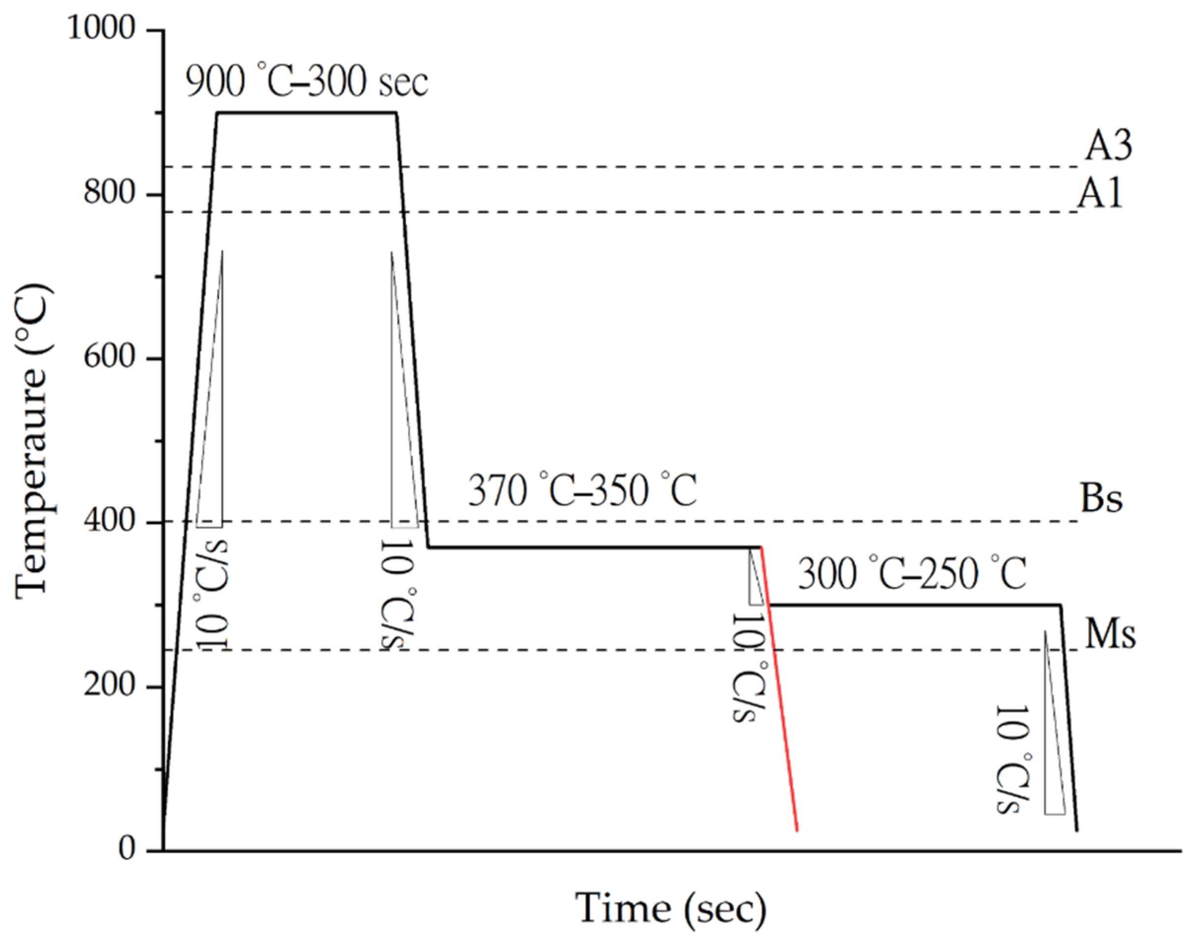
Alloy Production and Heat Treatments

A 40 kg ingot was produced through vacuum induction melting, heated at 1200 °C and hot rolled down to 20 mm in seven passes, followed by air-cooling to room temperature. The chemical composition was measured with optical emission spectroscopy (OES) and it is reported in Table 1.
ThermoCalc 2021 software (Thermo-Calc Software, Solna, Sweden) (with TCFE10 database) simulations were performed to calculate critical transformation temperatures, both for austenitisation and martensitic transformation (A1, A3, Ms) to design the heat treatments. Bainite start temperature (Bs) was calculated by means of the equation proposed by Zhao et al. [39]. Results are presented further in the manuscript.
Samples for dilatometry, with lengths 10 mm and 4 mm diameter, were machined employing electro-discharge machining from the steel plate in the direction perpendicular to the rolling direction. Dilatometric studies related to bainitic transformation were performed with a TA instrument quenching dilatometer DIL805A/D (TA Instrument, Hüllhorst, Germany). Based on ThermoCalc simulations a thermal cycle was performed for measuring the real Ac1, Ac3, and Ms of the investigated alloy. Specimen were heated at 10 °C/s at 900 °C and held for 5 min under vacuum (10−4 mbar) and cooled to room temperature in argon at 10 °C/s.
Three different multi-step treatment routes were selected in this research and are shown in Figure 1. The first route, called MULTISTEP1, consists of austenitisation at 900 °C for 5 min, followed by rapid cooling (10 °C/s) to the first bainite formation step at 370 °C until completion of bainitic reaction, and a second bainite formation step at 300 °C for further bainitic transformation, followed by final cooling to room temperature. The second one, named MULTISTEP2, is characterised by a second austempering treatment at 250 °C Finally, the so-called MULTISTEP3 consists of a first austempering treatment at 350 °C till the cessation of bainitic transformation and the second step at 250 °C. Single-step treatment with isothermal holding at 350 °C and 370 °C were also performed to compare the results. The heating rate (HR) and cooling rate (CR) of all heat treatments were set to be 10 °C/s. All the parameters for the heat treatments are listed in Table 2.
Microstructure characterisation was performed on heat-treated specimens following a standard metallographic practice. Final polishing was performed with diamond polycrystalline suspension of ¼ µm, followed by etching using a 5% Nital solution. Observation of the microstructure was performed with a Zeiss ULTRA55 Schottky field emission scanning electron microscope (Carl Zeiss NV, Zaventem, Belgium), operating at 15 kV and with an InLens detector. Thickness of bainitic ferrite was performed on SEM pictures taken at high magnification and analysed with the support of ImageJ software [40]. TEM observations, with a Philips CM30 (Philips NV, Amsterdam, The Netherlands) transmission electron microscope operating at 300 kV, were performed to resolve nanostructured microstructural features. Thin foil preparation involved mechanical thinning to 60 µm and twin-jet electropolished, with a Struers TENUPOL-3 (Struers S.A.S., Ballerup, Denmark), for the perforation of the 3 mm disk. The employed electrolyte consisted of 5% perchloric acid and 95% acetic acid [41,42,43]. X-ray diffraction measurements were carried out on polished samples to determine the volume fraction of retained austenite. Such characterisations were performed with a Bruker-D8 ADVANCE diffractometer (Bruker, Billerica, MA, USA), with a Cu Kα radiation at a voltage of 30 kV and a current of 30 mA. Analysis was performed in the 2θ of 40°–105°, with step scan 0.02° and acquisition time of 2 s. The volume fraction of retained austenite was calculated by performing Rietveld analysis with the support of Maud software (Luca Lutterotti, University of Trento, Trento, Italy) [44]. Carbon content (cγ) in retained austenite was calculated according to Equation (1), as a function of austenite lattice parameter (aγ), estimated from XRD Rietveld refinements [45]:
a γ = 3 . 5467 + 0 . 0467 c γ
For tensile tests, flat samples with a gauge length of 25 mm, a width of 6.25 mm, and 3 mm thickness mm were prepared by water-jet cutting and milling, according to ASTM A370-20. At least three samples were tested for each condition to ensure reproducibility and the average value was presented. Heat treatments on dog-bone samples for the tensile tests were performed with a Fours H&C muffle furnace (Fours H&C, Fernelmont, Belgium) for austenitisation, and lead and tin-lead bath furnaces, with eutectic composition, were used for bainitic transformation steps. An MTS (MTS System Corporation, Eden Prairie, MN, USA) with a 50 kN load cell was used for tensile tests, the force was measured using the machine load cell, while displacement was measured using the crosshead movement. Finally, the yield strength was calculated with the 0.2% method.

3. Results and Discussion

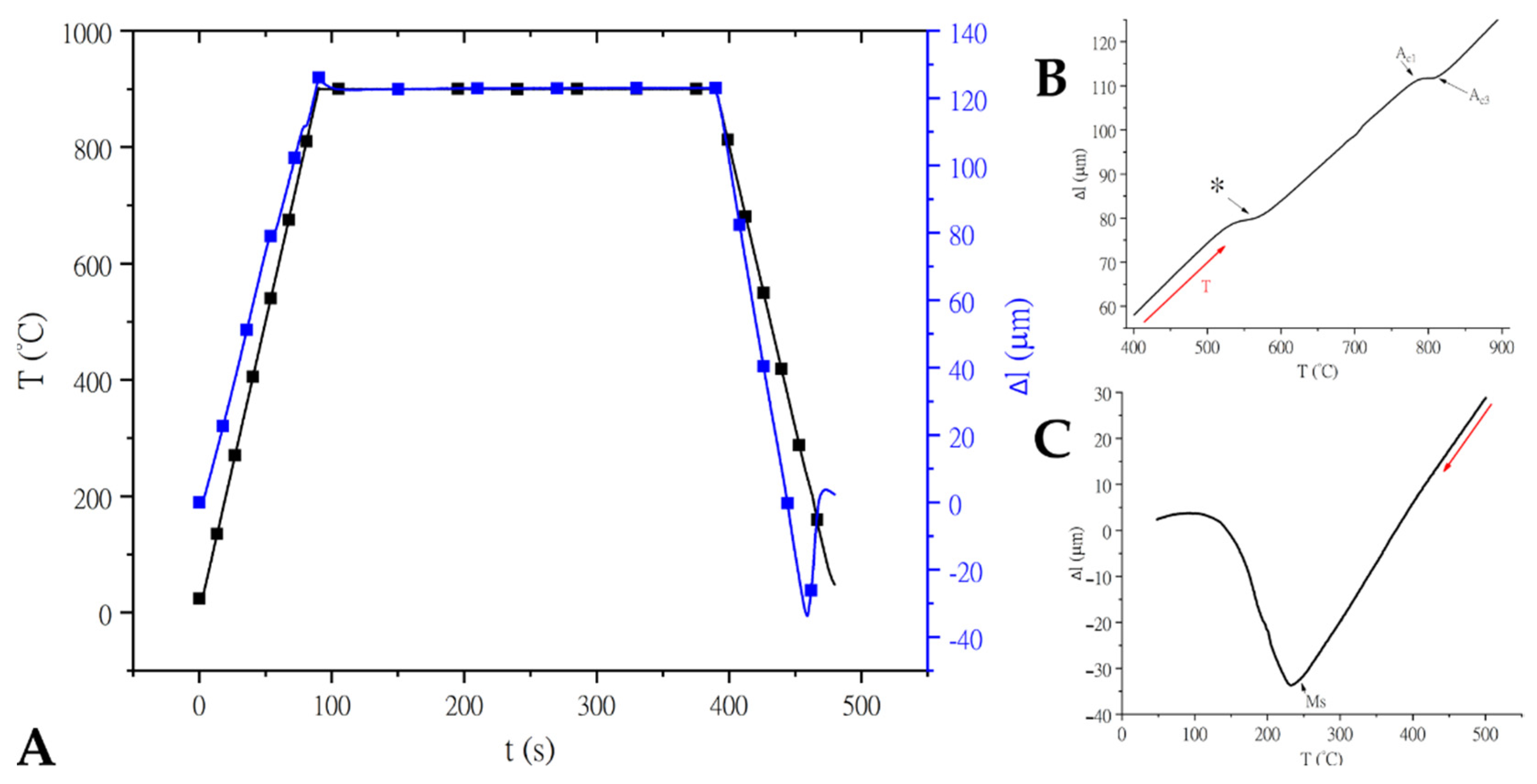
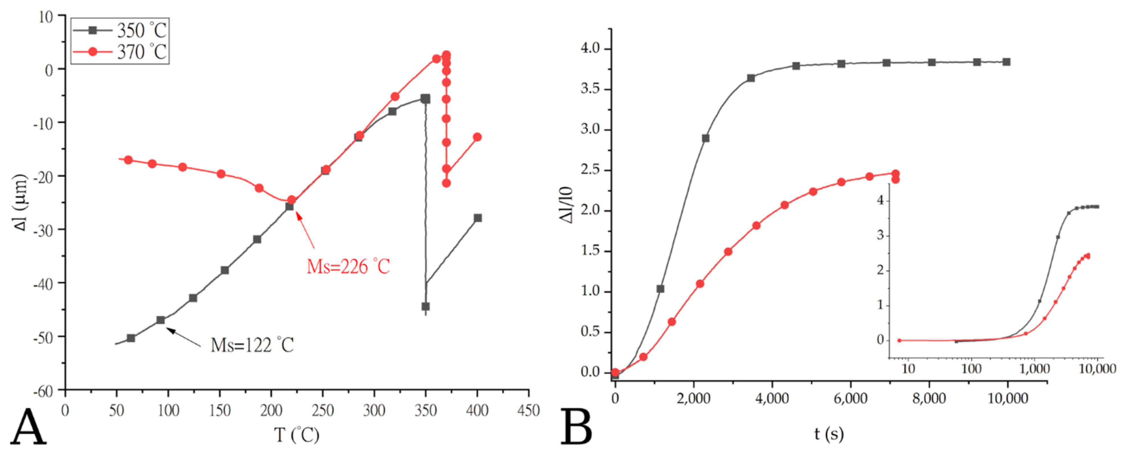
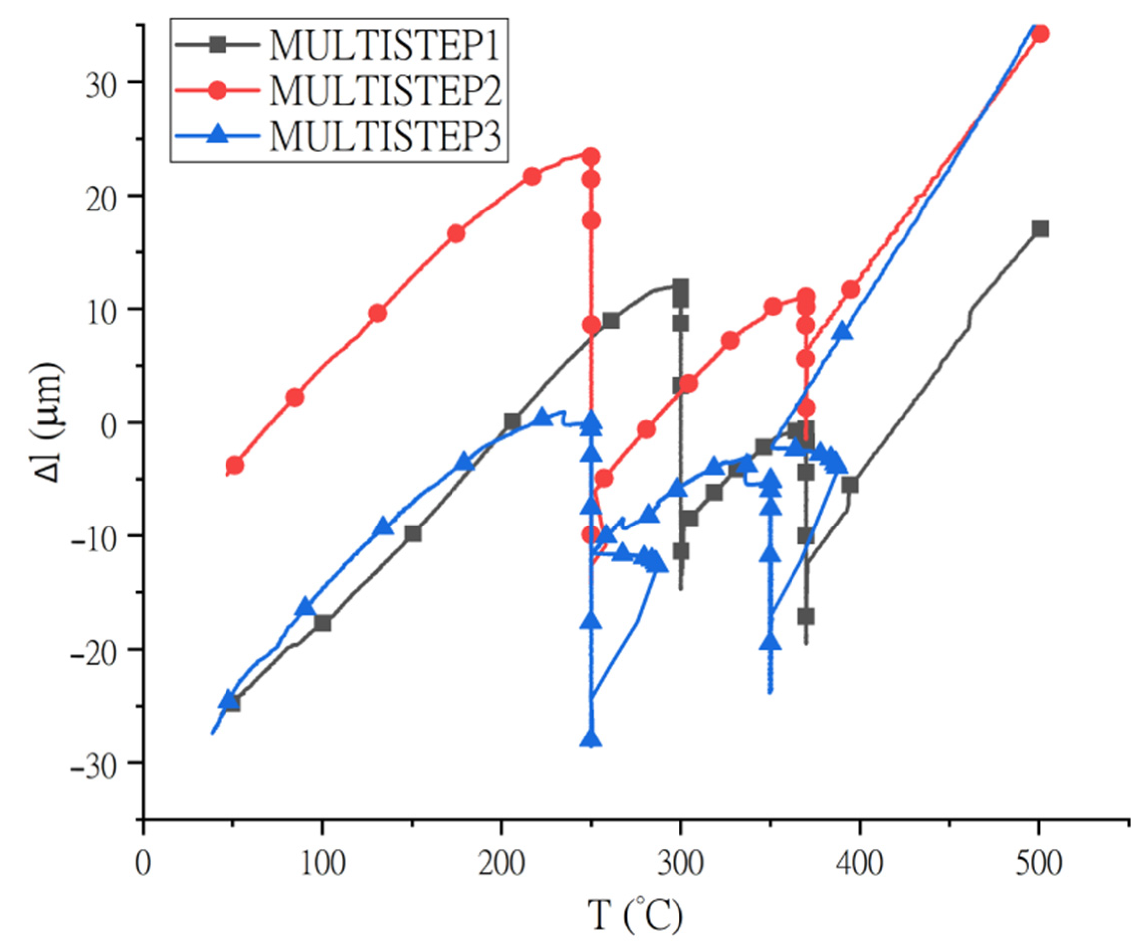
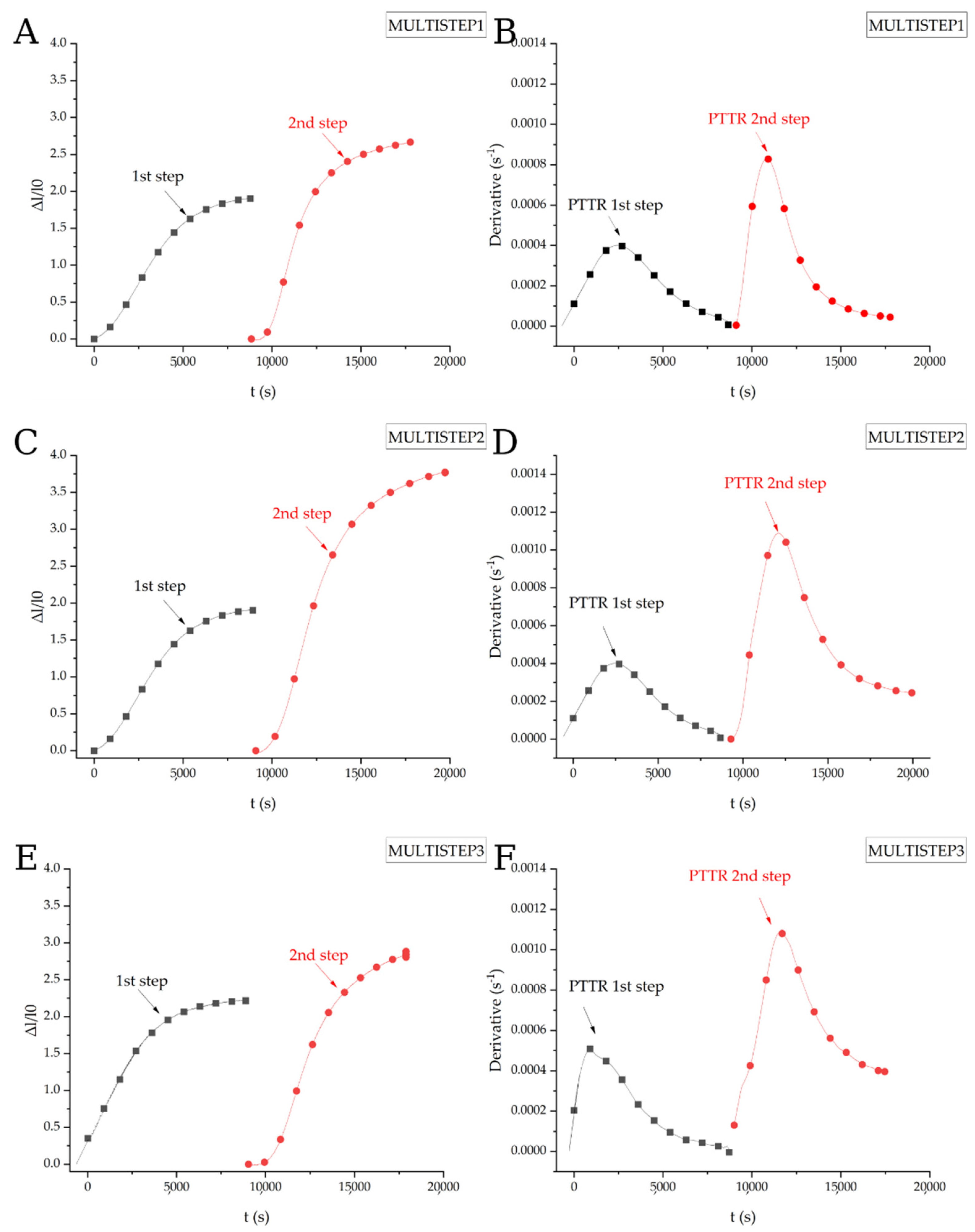
3.1. Thermocalc Analysis and Dilatometry

Calculated and measured critical transformation temperatures for the investigated alloy are reported in Table 3. Figure 2A shows the heat treatment cycle (black line) used for the estimation of the transformation temperature and the dilatation curve (blue line) obtained during the cycle. A linear contraction confirms that the chosen cooling rate is appropriate to prevent diffusional transformation. Figure 2B shows a detail of the heating branch of the change in length vs. temperature curve. Firstly, the heating is accompanied by a dilatation, with linear behaviour, connected to specimen thermal expansion, while at ≈520 °C, a first contraction, indicated by a star in the figure, can be observed. This refers to the microstructural evolution of the material in the as-received state, which was characterised by martensitic microstructure, at those temperature martensite tempers and cementite precipitates. The hypothesis is supported by El-Fallah and Bhadeshia for analogous heat treatments of medium carbon nickel alloyed steel with starting martensitic microstructure [46]. Once cementite precipitation is completed, at around 580 °C, change in length restarted following a linear pattern, due to linear expansion related to temperature increase. A second contraction was observed at 734 °C (A1) due to austenite growth and furthermore, the data indicated also that at 839 °C (corresponding to A3) the material is fully austenitic.
Finally, Figure 2C shows the lowest part of the cooling branch of the dilatation experiment, in which martensite starts temperature (Ms) at 245 °C can be observed.
Dilatometric results for single-stage treatments are shown in Figure 3A,B. Figure 3A shows the cooling branch of the thermal cycle, showing length variation during the isothermal holding period due to bainitic reaction for a single step at 350 °C and 370 °C. In both cases, final cooling to room temperature is followed by martensitc transformation, at 122 °C and 226 °C, respectively. Variation in the Ms values between the two specimens and respect to the previously measured value, for the as-received material, is connected with austenite carbon enrichment occurring during bainitic transformation, as reported by Bhadeshia [47]. Furthermore, Chupatanakul and Nash [48] demonstrated, combining dilatometry and relationship between carbon content and Ms, that as austenite carbon concentration increases the Ms values of the untransformed austenite decreases. The decrease in Ms from 226 °C to 122 °C reducing the isothermal holding temperature from 370 °C and 350 °C is explained considering the T0 curve theory and the thermodynamic of bainitic reaction [10,47]. As the temperature for bainite formation is reduced, higher is the maximum capability of austenite to accept carbon and, as consequence, lower Ms are achieved.
The relative changes in length during single-step treatment are reported in Figure 3B. The two curves indicate that lower temperature for the bainitic reaction leads to an increase in the extent of the bainitic reaction, as shown by the larger dilatation occurring during the isothermal treatment, as confirmed by Xu [49]. Furthermore, both for the isothermal treatment at 350 °C and 370 °C, the transformation is characterised by an incubation time (160 s and 300 s, respectively) as it is displayed in Figure 3B. Bainitic reaction at 350 °C is characterised by a shorter incubation period thanks to an increase in the driving force for bainitic transformation, in agreement with Khare et al. [50] and Zhou and co-authors [51]. In addition, the kinetics of the transformation at 350 °C is faster than the transformation at a higher temperature, as indicated by the more rapid increase in change in length, in agreement with Xu and co-authors [49].
Changes in length vs. temperature curves for multi-step treatments are then depicted in Figure 4. As expected, during isothermal holding an increase in specimen length is observed due to bainitic transformation [26,48,52]. For all the multistep heat treatments, no martensite formation is detected while cooling to room temperature. This suggests that after the second stage bainitic transformation, the retained austenite was enriched in carbon, thus lowering the Ms below room temperature [48,52].
Figure 5 shows the variation of the relative change in length as a function of the holding time for the different multi-stage treatments. All curves are characterised by the typical “S” shape of the isothermal solid-solid phase transformation curves in agreement with the curves proposed by Xu and San-Martin [49,53]. In the case of Figure 5A,C,E it is possible to observe for each step that the transformation starts slowly, and, in all the cases the incubation time that characterises the first stage of phase transformation is compatible with the one of the single-stage treatment. After that, a progressive increase in the transformation rate is observed, as testified by the derivative curves in Figure 5B,D,F. Comparing dilatometric curves of MULTISTEP1 and MULTISTEP2 routes, it is possible to observe that in the second stage of the treatment, performed, respectively, at 300 °C and 250 °C, more bainite is formed decreasing the temperature, thanks to the higher driving force [47]. Similarly, during the first stage of MULTISTEP3, the variation in specimen length is higher than the other two routes treated at higher temperatures in the first stage.
For both austempering stages in all multi-step heat treatments, the transformation rate increases until a “peak time transformation rate” (PTTR), followed by a decrease in the transformation rate [49,53,54].

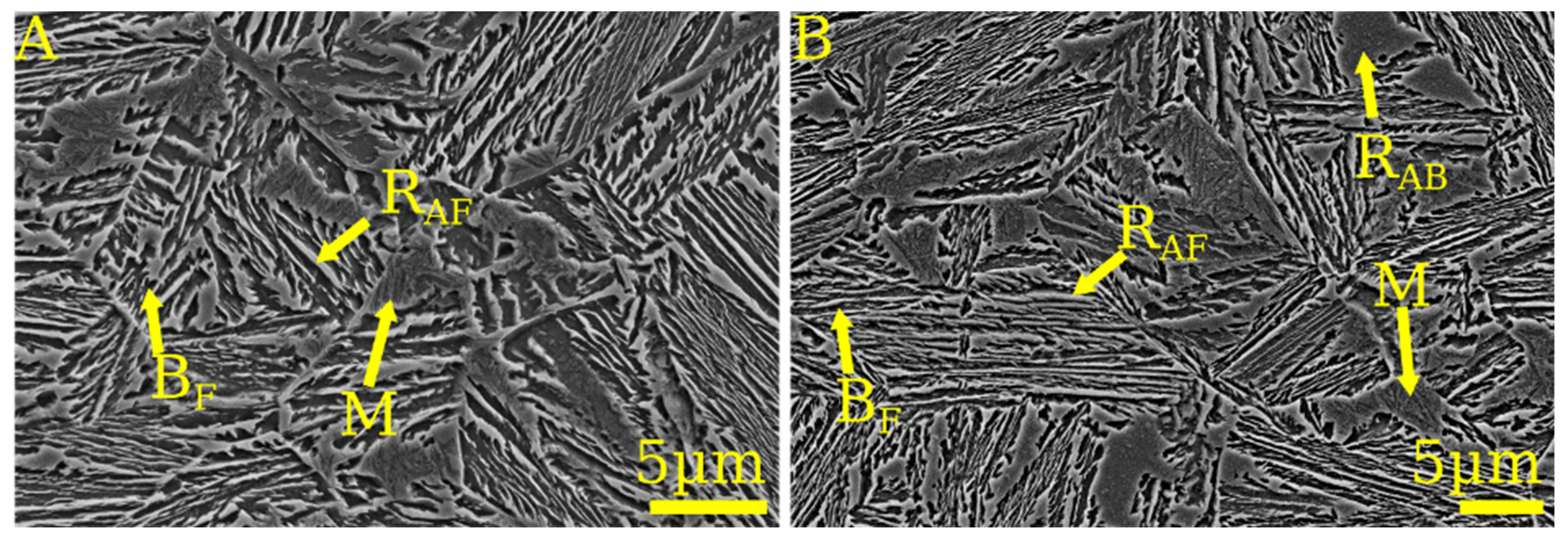
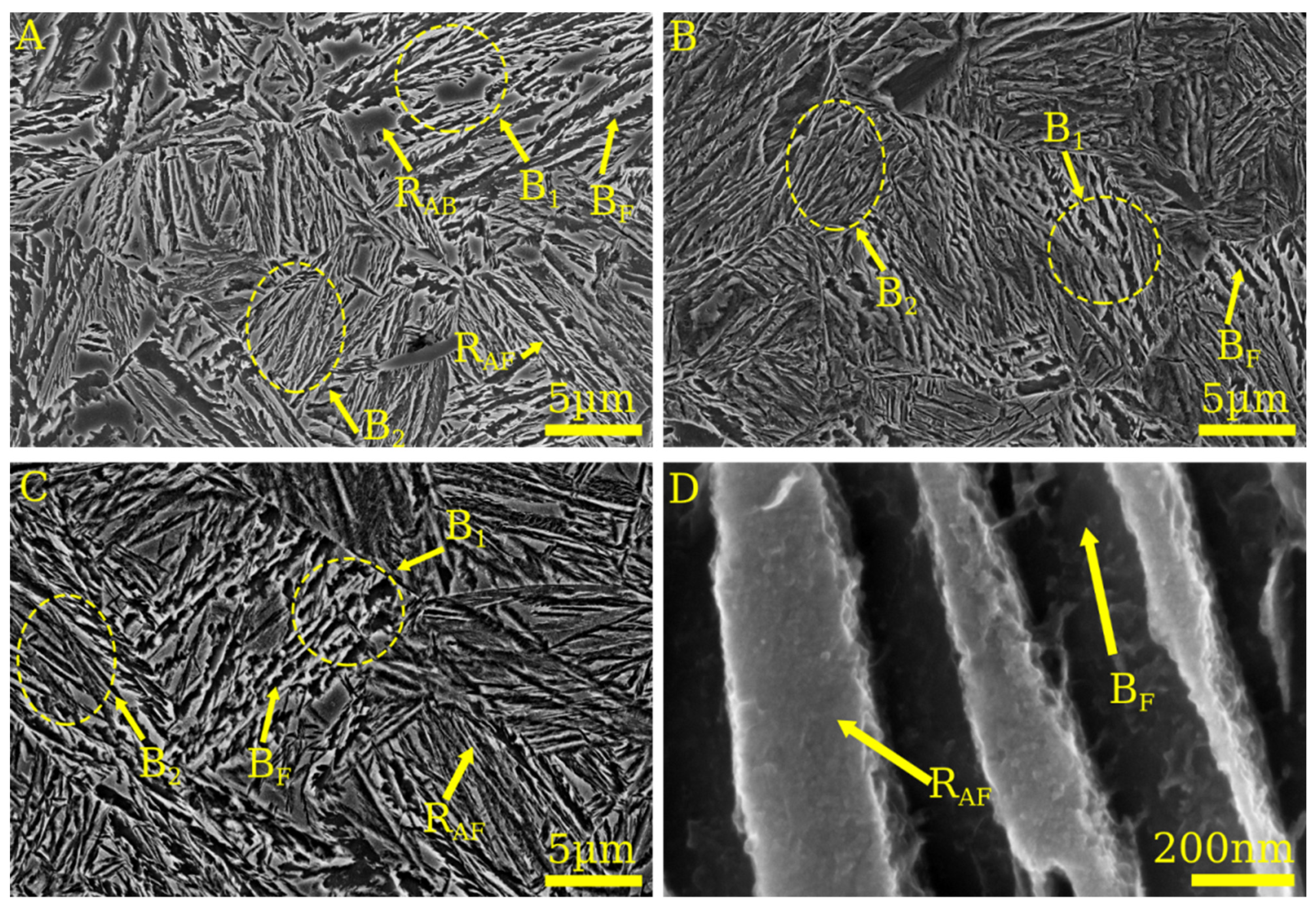
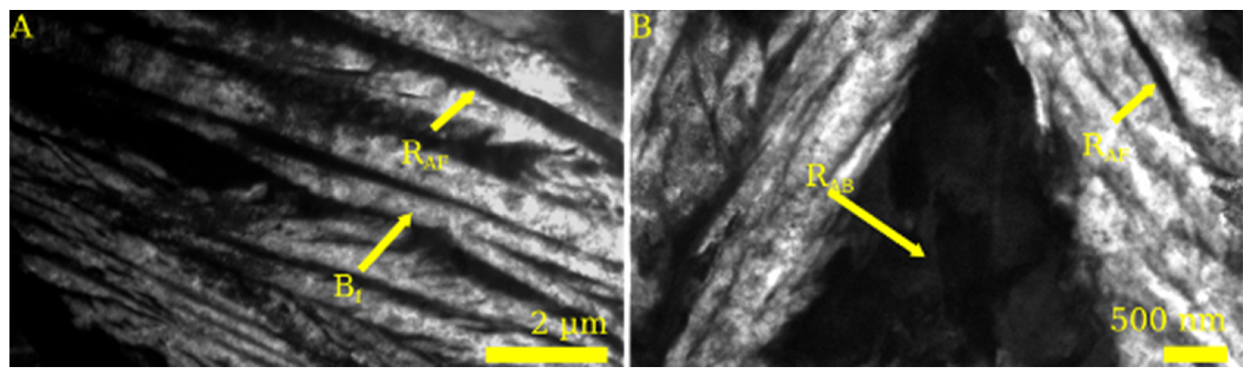
3.2. Microstructural Characterization

Figure 6A,B depicts SEM micrographs of the specimens after the single-step austempering treatments. Figure 6A shows the microstructure after isothermal holding at 370 °C for 2.5 h, time at which bainite transformation is completed according to Figure 3B. Although in Figure 6B the product of the bainitic transformation at 350 °C is shown. Both images illustrate that the microstructure consists of bainitic ferrite plates (dark grey) separated by high carbon enriched austenite in form of films (RAF) (light grey), as reported in the literature for similar steels [6,55,56,57]. Moreover, martensitic islands (M) and retained austenite blocks (RAB) are present in correspondence with the prior austenite grain boundaries, according to Zhao [52]. The formers are the product of partial martensite transformation of retained austenite, as supported by the dilatometric curves shown in Figure 3. Concerning the conventional single-step austempering process at 350 °C, the produced microstructures are also finer respect to the one formed at 370 °C, as demonstrated by the measurement of bainitic ferrite thickness, showed in Table 4. These results agree with those reported by other authors in the literature [37].
Figure 7A reports the microstructure of the sample treated with the MULTISTEP 1 heat treatment route. A carbide-free bainitic microstructure is observed with two different generations of bainitic shaves which are formed during the two steps of the isothermal bainitic transformation, which are indicated with yellow dashed circles and B1 and B2 in the images. There is a first coarser generation (B1) formed during the holding period at 370 °C, while the second is finer (B2) and formed during isothermal holding at 300 °C, as shown in Table 4 from the measurement of bainitic ferrite thickness at various isothermal holding temperature, and in accordance with Bhadeshia [37,47]. Moreover, the microstructure displays the product of martensitic transformation, suggesting a beneficial effect of the second isothermal treatment on retained austenite stability. The results lead to confirm the previous hypothesis in the discussion of the dilatometric curves, where the deviations from linearity were related to martensitic formation after single-step heat treatments, during the final cooling. During the second isothermal stage, untransformed austenite transforms in bainitic ferrite leading to further carbon enrichment, an increase in the amount of thin films able to contain more carbon, and a reduction in the volume fraction of austenite blocks.
Figure 7B shows the microstructural characterisation of MULTISTEP 2 which, as in the previous case, displays a microstructure consisting of two bainite generations. Finally, as for MULTISTEP 1, no martensite islands are present. A bimodal distribution on bainite is also observed after the MULTISTEP 3 route, as shown in Figure 7C. Thick plates of bainitic ferrite transform during the isothermal stage at 350 °C and the finer during the second stage at 250 °C, as reported in Table 4 as consequence of the thickness measurement of bainitic ferrite plates. One highlight of SEM observations is that the amount of blocky austenite is larger in MULTISTEP 1 than MULTISTEP 2 and MULTISTEP 3.
Finally, in Figure 7D is a high magnification SEM micrograph of bainitic sheaves of the sample treated according to MULTISTEP1, showing bainitic subunits with a thin films of retained austenite with thickness in nanoscale. Moreover, no carbides were observed thanks to the effect of silicon on suppression of cementite [58].
TEM analysis was performed on samples treated according to MULTISTEP3 route. Selected micrographs are shown in Figure 8. Bright-field image reported in Figure 8A depicts a shave of carbide-free bainite, with austenite films entrapped by bainitic ferrite sub-units, while in Figure 8B a block of retained austenite localized between different variants of bainite, with the typical polygonal shape, in 2D section [23].

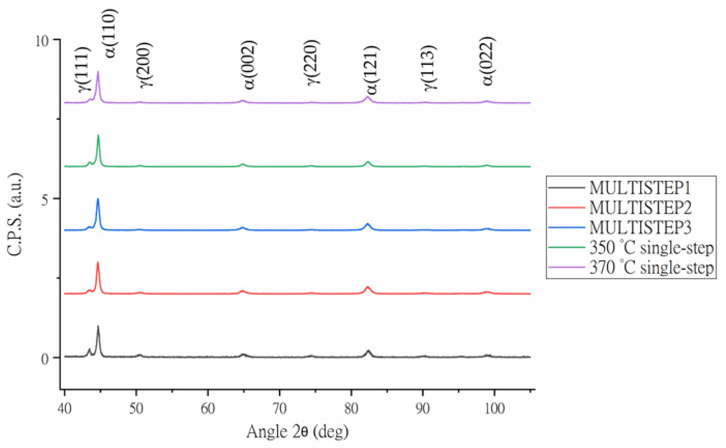
3.3. X-ray Diffraction

Figure 9 shows the diffraction patterns of all the specimens after the different treatment processes, both single-step and multistep. Then, the results of retained austenite quantification performed utilizing Rietveld analysis and evaluation of the carbon content are shown in Table 5. Peaks relative to BCC and FCC phases characterize all the patterns displayed in the figure.
For the single-step treatment, it is possible to observe that a reduction in holding temperature, during the isothermal treatment, from 370 °C to 350 °C leads to an increase in the austenite final amount, once the material is cooled down to ambient temperature. This result is in contrast with some results present in the literature, for example by Son et al. and Zhao and co-authors [7,16], that observed a reduction in the final total amount, thanks to the higher driving force associated with the bainitic reaction that is reduced when the temperature for the bainitic reaction is closer to Bs [50]. However, the opposite behaviour is explained considering the lower austenite carbon enrichment (0.81% vs. 0.87%) that occurs at a higher temperature, shown in the table, and therefore a lower austenite stabilization. This explanation is confirmed by both dilatometry and SEM observations, where martensitic transformation at 226 °C for the specimen treated at 370 °C occurs and whose product is visible in the micrographs. In addition, results are supported also by the work published by Putatunda et al. [59], in the same range of temperature. Two-step treatments are characterised by significant variations in the final content of retained austenite. In the case of MULTISTEP 1 and 2, the final austenite volume fraction is significantly higher than the one obtained with the single step at 370 °C. Such an increase from 12.9% to 23.4% and 17.97%, respectively, are associated with the double bainitic reaction mechanism. On the one hand, during a single-stage treatment at 370 °C the carbon enrichment and the extent of bainitic reaction is limited, as shown by dilatometry, i.e., retained austenite could not be stabilized at room temperature and undergo martensitic transformation during final cooling, as shown by SEM micrographs. On the other hand, performing a second step leads to a secondary bainitic reaction, which promotes a further carbon enrichment of surrounding austenite, leading to an increase in austenite stability, which is, therefore, retained at room temperature [16].
In the case of MULTISTEP3, a reduction in the final volume of austenite is observed thanks to the larger extent of the bainitic reaction occurring performing a two-stage treatment, in agreement with Avishan [33].
Comparing the different multi-step routes it is clear that depending on the temperature of the second isothermal stage the amount within the microstructure varies significantly. MULTISTEP2 leads to a decrease in austenite volume fraction with respect to MULTISTEP1 because of the second stage performed at a lower temperature that leads to larger decomposition of blocky austenite, in the second generation of bainite, at 250 °C respect to the one that occurred at 300 °C, as shown by Avishan and Mousalou [1,33].
In the case of multi-step treatment, a reduction in the value of the austenite carbon content (cγ) presented in Table 5 is observed passing from MULTISTEP2 to MULTISTEP3 due to the higher extent of the bainitic reaction occurring at lower temperature and consequent larger carbon enrichment from supersaturated ferrite. However, the presented value are the results of the applied model, cited in the previous section, considering an average lattice parameter of austenite without the possibility to distinguish different morphology of retained austenite (blocks and films) and the two different bainite distributions. Different techniques, as neutron diffraction, can provide more attainable results [60].

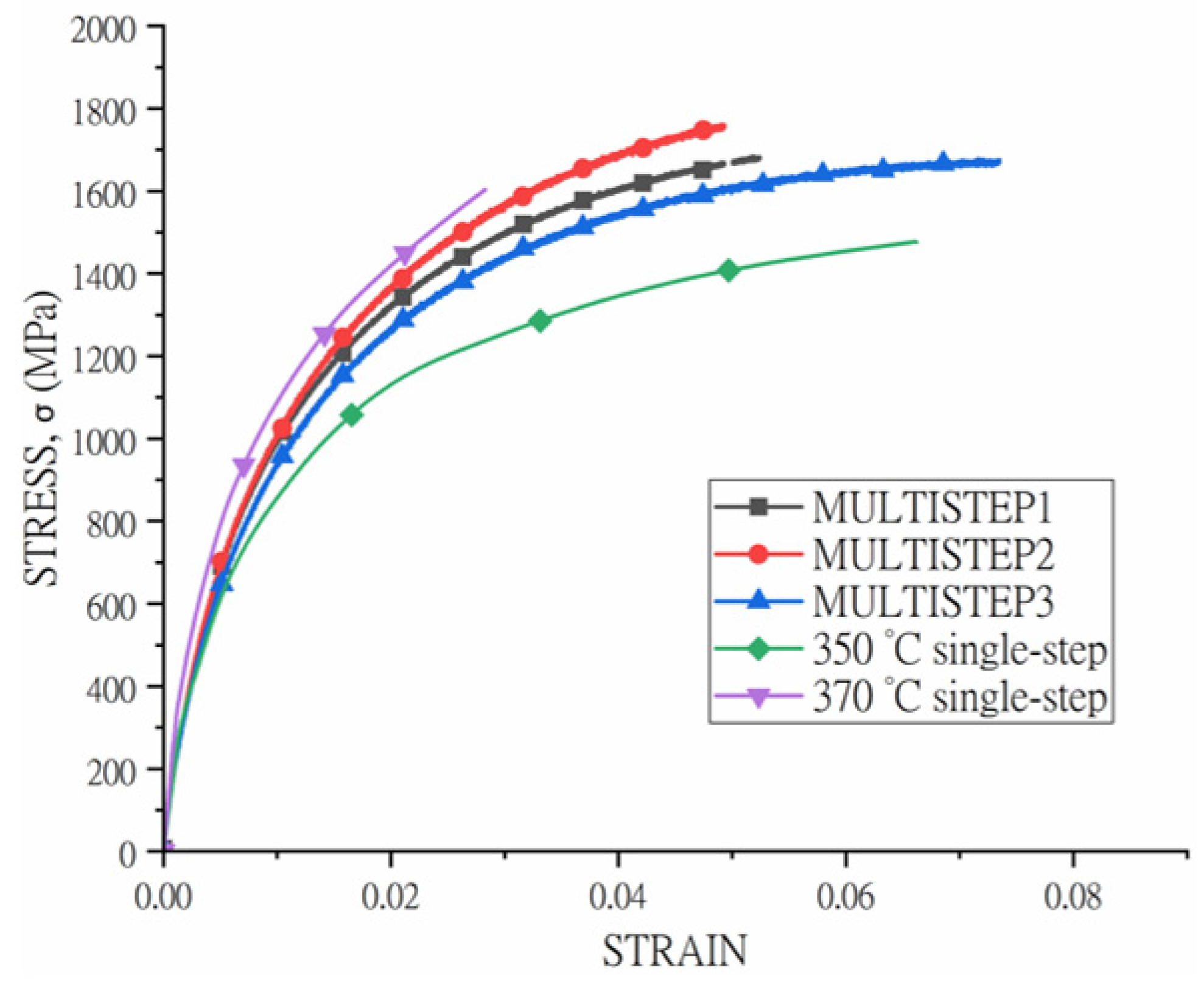
3.4. Mechanical Properties

Figure 10 shows the stress–strain engineering curves of the heat-treated samples, while results are resumed in Table 6. In the case of single isothermal treatment processes both yield strength and ultimate tensile strength decrease with the bainitic transformation temperature. This mechanical behaviour is consistent with the microstructural observation and results exposed in literature by many researchers, as Zhao and co-authors [61]. For lower isothermal holding conditions (350 °C) an improvement in terms of elongation to fracturing (from 0.028 to 0.066) was also observed, in agreement with Zhao [16]. Higher nucleation rate and yield strength of undercooled austenite at lower isothermal holding temperature produce finer bainitic ferrite plates, that combined with smaller and more stable blocks affects positively the mechanical response [16]. Moreover, in single-step processes continuous yielding is observable and the fracture is reached without necking and just showed uniform elongation, similarly with Avishan and co-authors [23]. As explained by the authors, the presence of austenite with low stability, transformation induced phenomena occur in the early stage of the tensile test. TRIP effect occurring at low strain level is, as matter of fact, detrimental.
Considering the multi-step routes, the results indicated that the treatments were successfully improving both ultimate tensile strength levels and elongations to fracture. In particular, MULTISTEP1 and MULTISTEP2 routes allow to improve fracture elongation from 0.028 to 0.052 and 0.049, respectively, and ultimate tensile strength from 1603 MPa to 1685 to 1761 MPa, respectively. Greater fracture elongation observed in the two-stage treatment, in comparison with the single-step treatment at 370 °C, is associated with lower content of untempered brittle martensite and lower amount and size of blocks of retained austenite [37]. The finer microstructure, deriving from the second isothermal stage, can compensate more efficiently, the damage occurring during stress application, giving as results better comprehensive properties, as proved also by [26]. Results agree with microstructural observation and X-ray diffraction and literature results proposed by Bhadeshia [37].
Moreover, both routes exhibit just uniform elongation without formation of neck and localized deformation before reaching fracture and without reduction in the sample area. Comparing MULTISTEP1 and 2, the improvement in terms of UTS is connected to the finer bainite during the second stage of the isothermal treatment in the case of MULTISTEP2. Concerning the MULTISTEP3 route greater values yielding point and UTS point are observable with respect to the single-stage treatment performed at 350 °C, while just a slight increase in total elongation characterises the two-step treated material. Higher yield strength is explained considering the increase in dislocation density and the carbon trapping in dislocation occurring during the two-step treatment [57].

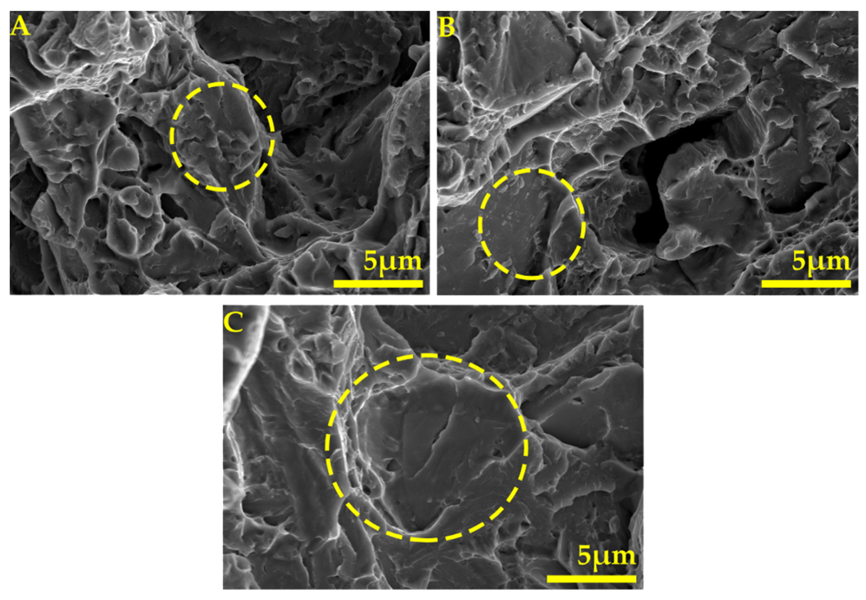
3.5. Fracture Surface Analysis

Figure 11 shows SEM micrographs of the fracture surface for all the multistep treatments. It is evident that the fractures are mainly composed of facets, evidenced in the figure by the yellow dashed circles, and are present in all the specimens. The aspect of the fracture surface is clearly in agreement with the tensile test curves, characterized by uniform elongation and the absence of necking and localised deformation, similarly to the results proposed by Avishan [23].
However, the mechanical behaviour and the morphology of the fracture surfaces are in contrast with several works in literature where specimens showed necking. This can find an explanation considering the mechanical austenite stability, as discussed by Garcia-Mateo [6,62]. Very fine filmy retained austenite can rich very high stability and it is not possible to obtain full advantage of TRIP effect, due to the small number of potential nucleation sites for martensitic transformation and to the large carbon content and other elements such Mn and Si that enhance austenite mechanical stability. As a consequence of high stable austenite, therefore, cannot provide effective TRIP effect and necking formation.

4. Conclusions

Five different heat treatment routes have been performed in this research. In particular, two single-step isothermal treatments were performed above Ms temperature, at 350 °C and 370 °C, and three two-step austempering routes. The following main conclusions can be drawn from the results:
(1)
Single-step isothermal treatments leads to microstructure containing bainitic ferrite, films of stable austenite, unstable block and hard brittle martensite. Such combination of microstructural constituents is responsible of poor elongation due to unfavourable TRIP effect;
(2)
Two steps routes lead to the formation of a bimodal bainite distribution, coarser bainite formed at a higher temperature, and finer bainite formed during the second stage. Moreover, the second step of the bainite reaction avoids the presence of large martensitic islands in the final microstructure;
(3)
In addition, the second step of bainitic reaction leads to a further increase in austenite carbon content, improving the thermal stability of retained austenite;
(4)
Two-step treatments lead to improve mechanical properties in terms both of ductility (fracture elongation) and ultimate tensile strength.

Author Contributions

Conceptualization, M.D.; methodology, L.P., A.M.B., software, P.J.J., M.F., A.M.B.; validation, L.P., P.J.J., A.M.B.; formal analysis, M.F., A.M.B.; investigation, M.F., A.M.B.; resources, M.D., P.J.J.; data curation, M.F., L.P.; writing—original draft preparation, M.F., L.P.; writing—review and editing, L.P., A.M.B.; visualization, M.F., A.M.B.; supervision, M.D., P.J.J.; project administration, M.D., P.J.J., funding acquisition, M.D. All authors have read and agreed to the published version of the manuscript.

Funding

The research was in the frame of the “Progetto di grande rilevanza Italia-Russia” “Investigation on 3d-printing of Advanced High Strength Steels with TRIP effect for realization of self-adapting aerospace structural elements”, financed by the Ministero degli Affari Esteri e della Cooperazione Internazionale MAECI.

Institutional Review Board Statement

Not applicable.

Informed Consent Statement

Not applicable.

Data Availability Statement

The raw/processed data required to reproduce these findings cannot be shared at this time as the data also form part of an ongoing study.

Conflicts of Interest

The authors declare no conflict of interest.

References

  1. Mousalou, H.; Yazdani, S.; Avishan, B.; Ahmadi, N.P.; Chabok, A.; Pei, Y. Microstructural and mechanical properties of low-carbon ultra-fine bainitic steel produced by multi-step austempering process. Mater. Sci. Eng. A 2018, 734, 329–337. [Google Scholar] [CrossRef]
  2. Edmonds, D.V. Advanced bainitic and martensitic steels with carbide-free microstructures containing retained austenite. Mater. Sci. Forum 2010, 638–642, 110–117. [Google Scholar] [CrossRef]
  3. Caballero, F.G.; Bhadeshia HK, D.H.; Mawella KJ, A.; Jones, D.G.; Brown, P. Very strong low temperature bainite. Mater. Sci. Technol. 2002, 18, 279–284. [Google Scholar] [CrossRef] [Green Version]
  4. Gola, A.M.; Ghadamgahi, M.; Ooi, S.W. Microstructure evolution of carbide-free bainitic steels under abrasive wear conditions. Wear 2017, 376–377, 975–982. [Google Scholar]
  5. Tian, J.; Xu, G.; Jiang, Z.; Wan, X.; Hu, H.; Yuan, Q. Transformation Behavior and Properties of Carbide-Free Bainite Steels with Different Si Contents. Steel Res. Int. 2019, 90, 1800474. [Google Scholar] [CrossRef] [Green Version]
  6. Garcia-Mateo, C.; Caballero, F.G.; Sourmail, T.; Kuntz, M.; Cornide, J.; Smanio, V.; Elvira, R. Tensile behaviour of a nanocrystalline bainitic steel containing 3wt% silicon. Mater. Sci. Eng. A 2012, 549, 185–192. [Google Scholar] [CrossRef] [Green Version]
  7. Son, J.Y.; Kim, J.H.; Kim, W.B.; Ye, B.J. Effects of austempering conditions on the microstructures and mechanical properties in Fe-0.9%C-2.3%Si-0.3%Mn steel. Met. Mater. Int. 2010, 16, 357–361. [Google Scholar] [CrossRef]
  8. Franceschi, M.; Pezzato, L.; Settimi, A.G.; Gennari, C.; Pigato, M.; Polyakova, M.; Konstantinov, D.; Brunelli, K.; Dabal, M. Effect of Different Austempering Heat Treatments on Corrosion Properties of High Silicon Steel. Materials 2021, 14, 288. [Google Scholar]
  9. Bhadeshia, H.K.D.H.; Edmonds, D.V. Bainite in silicon steels: New composition-property approach part 1. Met. Sci. 1983, 17, 411–419. [Google Scholar] [CrossRef]
  10. Kumar, A.; Makineni, S.K.; Dutta, A.; Goulas, C.; Steenbergen, M.; Petrov, R.H.; Sietsma, J. Design of high-strength and damage-resistant carbide-free fine bainitic steels for railway crossing applications. Mater. Sci. Eng. A 2019, 759, 210–223. [Google Scholar] [CrossRef]
  11. Toloui, M.; Militzer, M. Phase field modeling of the simultaneous formation of bainite and ferrite in TRIP steel. Acta Mater. 2018, 144, 786–800. [Google Scholar] [CrossRef]
  12. Podder, A.S.; Lonardelli, I.; Molinari, A.; Bhadeshia, H.K.D.H. Thermal stability of retained austenite in bainitic steel: An in situ study. In Proceedings of the Royal Society A: Mathematical, Physical and Engineering Sciences; The Royal Society: London, UK; 2011; Volume 467, pp. 3141–3156. [Google Scholar]
  13. Changle, Z.; Hanguang, F.; Shengqiang, M.; Jian, L.; Yongping, L. Microstructure and properties of high-Si high-Mn bainitic steel after heat treatment. Mater. Res. Express 2019, 6, 0965a8. [Google Scholar] [CrossRef]
  14. Fu, B.; Yang, W.Y.; Li, L.F.; Sun, Z.Q. Effect of bainitic transformation temperature on the mechanical behavior of cold-rolled TRIP steels studied with in-situ high-energy X-ray diffraction. Mater. Sci. Eng. A 2014, 603, 134–140. [Google Scholar] [CrossRef]
  15. Bollinger, A.L.; Murakami, T.; Findley, K.O.; de Moor, E.; Speer, J.G. The influence of microstructural variations on hydrogen absorbance and tensile properties at elevated hydrogen levels for TRIP-aided bainitic ferrite steels. Corrosion 2019, 75, 888–897. [Google Scholar] [CrossRef]
  16. Zhao, J.; Lv, B.; Zhang, F.; Yang, Z.; Qian, L.; Chen, C.; Long, X. Effects of austempering temperature on bainitic microstructure and mechanical properties of a high-C high-Si steel. Mater. Sci. Eng. A 2019, 742, 179–189. [Google Scholar] [CrossRef]
  17. Meng, J.; Zhao, L.; Huang, F.; Zhang, F.; Qian, L. Isothermal transformation, microstructure and mechanical properties of ausformed low-carbon carbide-free bainitic steel. Mater. Sci. Forum 2018, 941, 329–333. [Google Scholar] [CrossRef]
  18. Pashangeh, S.; Somani, M.; Banadkouki, S.S.G. Microstructural evolution in a high-silicon medium carbon steel following quenching and isothermal holding above and below the Ms temperature. J. Mater. Res. Technol. 2020, 9, 3438–3446. [Google Scholar] [CrossRef]
  19. Navarro-López, A.; Hidalgo, J.; Sietsma, J.; Santofimia, M.J. Characterization of bainitic/martensitic structures formed in isothermal treatments below the Ms temperature. Mater. Charact. 2017, 128, 248–256. [Google Scholar] [CrossRef]
  20. Chang, L.C.; Bhadeshia, H.K.D.H. Austenite films in bainitic microstructures. Mater. Sci. Technol. 2012, 11, 874–882. [Google Scholar] [CrossRef]
  21. Efremenko, V.G.; Hesse, O.; Friedrich, T.; Kunert, M.; Brykov, M.N.; Shimizu, K.; Zurnadzhy, V.I.; Šuchmann, P. Two-body abrasion resistance of high-carbon high-silicon steel: Metastable austenite vs nanostructured bainite. Wear 2019, 418–419, 24–35. [Google Scholar] [CrossRef]
  22. Gao, G.; Zhang, H.; Gui, X.; Luo, P.; Tan, Z.; Bai, B. Enhanced ductility and toughness in an ultrahigh-strength Mn-Si-Cr-C steel: The great potential of ultrafine filmy retained austenite. Acta Mater. 2014, 76, 425–433. [Google Scholar] [CrossRef]
  23. Avishan, B.; Yazdani, S.; Caballero, F.G.; Wang, T.; Garcia-Mateo, C. Characterization of Microstructure and Mechanical Properties in Two Different Nanostructured Bainitic Steels. Mater. Sci. Technol. 2015, 31, 1508–1520. [Google Scholar] [CrossRef] [Green Version]
  24. Mousalou, H.; Yazdani, S.; Parvini Ahmadi, N.; Avishan, B. Nanostructured Carbide-Free Bainite Formation in Low Carbon Steel. Acta Metall. Sin. English Lett. 2020, 33, 1635–1644. [Google Scholar] [CrossRef]
  25. Gao, G.; Guo, H.; Gui, X.; Tan, Z.; Bai, B. Inverted multi-step bainitic austempering process routes: Enhanced strength and ductility. Mater. Sci. Eng. A 2018, 736, 298–305. [Google Scholar] [CrossRef]
  26. Tian, J.; Xu, G.; Jiang, Z.; Zhou, M.; Hu, H.; Yuan, Q. Transformation behavior of bainite during two-step isothermal process in an ultrafine bainite steel. ISIJ Int. 2018, 58, 1875–1882. [Google Scholar] [CrossRef]
  27. Zhang, M.; Qian, J.; Gu, H. The structure stability of carbide-free bainite wheel steel. J. Mater. Eng. Perform. 2007, 16, 635–639. [Google Scholar] [CrossRef]
  28. Chiang, J.; Lawrence, B.; Boyd, J.D.; Pilkey, A.K. Effect of microstructure on retained austenite stability and work hardening of TRIP steels. Mater. Sci. Eng. A 2011, 528, 4516–4521. [Google Scholar] [CrossRef]
  29. Matsuda, H.; Noro, H.; Nagataki, Y.; Hosoya, Y. Effect of retained austenite stability on mechanical properties of 590MPa grade TRIP sheet steels. Mater. Sci. Forum 2010, 638–642, 3374–3379. [Google Scholar] [CrossRef]
  30. Sherif, M.Y.; García Mateo, C.; Sourmail, T.; Bhadeshia, H.K.D.H. Stability of retained austenite in TRIP-assisted steels. Mater. Sci. Technol. 2004, 20, 319–322. [Google Scholar] [CrossRef] [Green Version]
  31. Garcia-Mateo, C.; Caballero, F.G.; Chao, J.; Capdevila, C.; Garcia De Andres, C. Mechanical stability of retained austenite during plastic deformation of super high strength carbide free bainitic steels. J. Mater. Sci. 2009, 44, 4617–4624. [Google Scholar] [CrossRef]
  32. Lan, L.Y.; Qiu, C.L.; Zhao, D.W.; Gao, X.H.; Du, L.X. Effect of austenite grain size on isothermal bainite transformation in low carbon microalloyed steel. Mater. Sci. Technol. 2011, 27, 1657–1663. [Google Scholar]
  33. Avishan, B.; Tavakolian, M.; Yazdani, S. Two-step austempering of high performance steel with nanoscale microstructure. Mater. Sci. Eng. A 2017, 693, 178–185. [Google Scholar] [CrossRef]
  34. Wang, X.L.; Wu, K.M.; Hu, F.; Yu, L.; Wan, X.L. Multi-step isothermal bainitic transformation in medium-carbon steel. Scr. Mater. 2014, 74, 56–59. [Google Scholar] [CrossRef]
  35. Chu, C.; Qin, Y.; Li, X.; Yang, Z.; Zhang, F.; Guo, C.; Long, X.; You, L. Effect of two-step austempering process on transformation kinetics of nanostructured bainitic steel. Materials 2019, 12, 166. [Google Scholar] [CrossRef] [PubMed] [Green Version]
  36. He, J.; Zhao, A.; Zhi, C.; Fan, H. Acceleration of nanobainite transformation by multi-step ausforming process. Scr. Mater. 2015, 107, 71–74. [Google Scholar] [CrossRef]
  37. Hase, K.; Garcia-Mateo, C.; Bhadeshia, H.K.D.H. Bimodal size-distribution of bainite plates. Mater. Sci. Eng. A 2006, 438–440, 145–148. [Google Scholar] [CrossRef] [Green Version]
  38. Soliman, M.; Mostafa, H.; El-Sabbagh, A.S.; Palkowski, H. Low temperature bainite in steel with 0.26wt% C. Mater. Sci. Eng. A 2010, 527, 7706–7713. [Google Scholar] [CrossRef]
  39. Scheuer, C.J.; Cardoso, R.P.; Mafra, M.; Brunatto, S.F. AISI 420 martensitic stainless steel low-temperature plasma assisted carburizing kinetics. Surf. Coat. Technol. 2013, 214, 30–37. [Google Scholar] [CrossRef] [Green Version]
  40. Abramoff, M.; Magalhães, P.J.; Ram, S.J. The aim of the present study was to inves- tigate the details of overall transformation kinetics, microstruc- tures and tensile properties of multi-step ausformed high carbon nanobainite. Biophotonics Int. 2004, 11, 36–42. [Google Scholar]
  41. Franceschi, M.; Pezzato, L.; Gennari, C.; Fabrizi, A.; Polyakova, M.; Konstantinov, D.; Brunelli, K.; Dabalà, M. Effect of intercritical annealing and austempering on the microstructure and mechanical properties of a high silicon manganese steel. Metals 2020, 10, 1448. [Google Scholar] [CrossRef]
  42. Pezzato, L.; Gennari, C.; Chukin, D.; Toldo, M.; Sella, F.; Toniolo, M.; Zambon, A.; Brunelli, K.; Dabalà, M. Study of the effect of multiple tempering on the impact toughness of forged s690 structural steel. Metals 2020, 10, 507. [Google Scholar] [CrossRef] [Green Version]
  43. Spezzapria, M.; Settimi, A.G.; Pezzato, L.; Novella, M.F.; Forzan, M.; Dughiero, F.; Bruschi, S.; Ghiotti, A.; Brunelli, K.; Dabalà, M. Effect of Prior Microstructure and Heating Rate on the Austenitization Kinetics of 39NiCrMo3 Steel. Steel Res. Int. 2017, 88, 1600267. [Google Scholar] [CrossRef]
  44. L. Lutterotti, Maud: A Rietveld analysis program designed for the internet and experiment integration. Acta Crystallogr. Sect. A Found. Crystallogr. 2000, 56, s54. [CrossRef] [Green Version]
  45. Sugimoto, K.-I.; Nakano, K.; Song, S.-M.; Kashima, T. Retained Austenite Characteristics and Stretch-Flangeability of High-Strength Low-Alloy TRIP Type Bainitic Sheet Steels. ISIJ Int. 2002, 42, 450–455. [Google Scholar] [CrossRef]
  46. El-Fallah GM, A.M.; Ooi, S.W.; Bhadeshia, H.K.D.H. Effect of nickel aluminide on the bainite transformation in a Fe-0.45C–13Ni–3Al–4Co steel, and associated properties. Mater. Sci. Eng. A 2019, 767, 138362. [Google Scholar] [CrossRef]
  47. Bhadeshia, H.K.D.H. Bainite in Steels: Theory and Practice; Maney Publishing: Leeds, UK, 2006; Volume 19. [Google Scholar]
  48. Chupatanakul, S.; Nash, P. Dilatometric measurement of carbon enrichment in austenite during bainite transformation. J. Mater. Sci. 2006, 41, 4965–4969. [Google Scholar] [CrossRef]
  49. Xu, Y.; Xu, G.; Mao, X.; Zhao, G.; Bao, S. Method to evaluate the kinetics of bainite transformation in low-temperature nanobainitic steel using thermal dilatation curve analysis. Metals 2017, 7, 330. [Google Scholar] [CrossRef] [Green Version]
  50. Khare, S.; Lee, K.; Bhadeshia, H.K.D.H. Carbide-free bainite: Compromise between rate of transformation and properties. Metall. Mater. Trans. A Phys. Metall. Mater. Sci. 2010, 41, 922–928. [Google Scholar] [CrossRef] [Green Version]
  51. Zou, H.; Hu, H.; Xu, G.; Xiong, Z.; Dai, F. Combined effects of deformation and undercooling on isothermal bainitic transformation in an Fe-C-Mn-Si alloy. Metals 2019, 9, 138. [Google Scholar] [CrossRef] [Green Version]
  52. Zhao, J.; Zhang, F.; Lv, B.; Yang, Z.; Chen, C.; Long, X.; Zhao, X.; Chu, C. Inconsistent effects of austempering time within transformation stasis on monotonic and cyclic deformation behaviors of an ultrahigh silicon carbide-free nanobainite steel. Mater. Sci. Eng. A 2019, 751, 80–89. [Google Scholar] [CrossRef]
  53. San-Martin, D.; Kuntz, M.; Caballero, F.G.; Garcia-Mateo, C. A new systematic approach based on dilatometric analysis to track bainite transformation kinetics and the influence of the prior austenite grain size. Metals 2021, 11, 324. [Google Scholar] [CrossRef]
  54. Xu, G.; Liu, F.; Wang, L.; Hu, H. A new approach to quantitative analysis of bainitic transformation in a superbainite steel. Scr. Mater. 2013, 68, 833–836. [Google Scholar] [CrossRef]
  55. Leiro, A.; Vuorinen, E.; Sundin, K.G.; Prakash, B.; Sourmail, T.; Smanio, V.; Caballero, F.G.; Garcia-Mateo, C.; Elvira, R. Wear of nano-structured carbide-free bainitic steels under dry rolling-sliding conditions. Wear 2013, 298–299, 42–47. [Google Scholar] [CrossRef] [Green Version]
  56. Morales-Rivas, L.; González-Orive, A.; Garcia-Mateo, C.; Hernández-Creus, A.; Caballero, F.G.; Vázquez, L. Nanomechanical characterization of nanostructured bainitic steel: Peak Force Microscopy and Nanoindentation with AFM. Sci. Rep. 2015, 5, 17164. [Google Scholar] [CrossRef] [Green Version]
  57. Zhao, F.Y.; Chen, P.; Xu, B.Y.; Yu, Q.; Wang, G.D.; Yi, H.L. A carbide-free bainitic steel with high-ductility by dynamic transformation during coiling process. Mater. Sci. Technol. 2020, 36, 1704–1711. [Google Scholar] [CrossRef]
  58. Qian, L.; Zhou, Q.; Zhang, F.; Meng, J.; Zhang, M.; Tian, Y. Microstructure and mechanical properties of a low carbon carbide-free bainitic steel co-alloyed with Al and Si. Mater. Des. 2012, 39, 264–268. [Google Scholar] [CrossRef]
  59. Putatunda, S.K. Influence of austempering temperature on microstructure and fracture toughness of a high-carbon, high-silicon and high-manganese cast steel. Mater. Des. 2003, 24, 435–443. [Google Scholar] [CrossRef]
  60. Gong, W.; Tomota, Y.; Adachi, Y.; Paradowska, A.M.; Kelleher, J.F.; Zhang, S.Y. Effects of ausforming temperature on bainite transformation, microstructure and variant selection in nanobainite steel. Acta Mater. 2013, 61, 4142–4154. [Google Scholar] [CrossRef]
  61. Zhao, Z.Z.; Yin, H.X.; Zhao, A.M.; Gong, Z.Q.; He, J.G.; Tong, T.T.; Hu, H.J. The influence of the austempering temperature on the transformation behavior and properties of ultra-high-strength TRIP-aided bainitic-ferritic sheet steel. Mater. Sci. Eng. A 2014, 613, 8–16. [Google Scholar] [CrossRef]
  62. Avishan, B.; Garcia-Mateo, C.; Morales-Rivas, L.; Yazdani, S.; Caballero, F.G. Strengthening and mechanical stability mechanisms in nanostructured bainite. J. Mater. Sci. 2013, 48, 6121–6132. [Google Scholar] [CrossRef] [Green Version]
Figure 1. Bainitic multi-step heat treatment cycles after austenitisation at 900 °C for 5 min.
Metals 11 02055 g001
Figure 2. (A) Thermal cycle for the dilatometric study of critical temperature Ac1, Ac3, Ms (black line), and dilatation curve (blue line); (B) relative change in length against temperature curve indicating austenitisation transformation and the temperature Ac1 and Ac3; the star (*) = indicates cementite precipitation during heating of martensite due to carbon rejection; (C) cooling branch of the thermal cycle indicating Ms temperature and martensitic transformation.
Metals 11 02055 g002
Figure 3. (A) Cooling branch of the dilatometric curve showing the change in length (∆l) against temperature for the single-step austempering treatment (A,B) Cooling branch of the dilatometric curve showing the change in length (∆l) against temperature for the single-step austempering treatment (B) dilatometric curve showing the change in length with time. The insert in (B) better shows the incubation time for both bainite transformations.
Metals 11 02055 g003
Figure 4. Cooling branch of the dilatometric curve showing the change in length (∆l) against temperature for the multi-step austempering treatments indicating the bainitic transformation during all the austempering steps.
Metals 11 02055 g004
Figure 5. (A,C,E) relative change in length vs. austempering time curve for the heat treatment MULTISTEP 1, MULTISTEP 2, MULTISTEP 3, respectively. (B,D,F) Derivative of the relative change in length against time treatment describing the kinetic of the bainitic transformation during MULTISTEP 1, MULTISTEP 2, MULTISTEP 3 respectively.
Metals 11 02055 g005
Figure 6. SEM micrograph of the sample treated with a single-step austempering until completion of the bainitic transformation at (A) 370 °C and (B) 350 °C. RAF: retained austenite film; BF: bainitic ferrite; RAB: retained austenite block; M: martensite.
Metals 11 02055 g006
Figure 7. (AC) SEM micrograph of the sample treated according to route MULTISTEP 1, MULTISTEP2, MULTISTEP3, respectively. (D) High magnification SEM micrograph showing filmy of retained austenite and bainitic ferrite. B1: carbide-free bainite formed during the first isothermal holding step; B2: carbide-free bainite formed during the second isothermal holding step. RAF: retained austenite film; BF: bainitic ferrite; RAB: retained austenite block; M: martensite.
Metals 11 02055 g007
Figure 8. TEM micrographs on the samples treated according to MULTISTEP3 route (A) Bainitic sheave, (B) Retained austenite block between bainitic sheaves.
Metals 11 02055 g008
Figure 9. XRD patterns for the different heat treatment routes.
Metals 11 02055 g009
Figure 10. Engineering stress–engineering strain curves of the heat-treated steel samples (yield strength was calculated with the 0.2 criteria).
Metals 11 02055 g010
Figure 11. Fracture surfaces of the heat-treated steel samples after (A) MULTISTEP1, (B) MULTISTEP2, (C) MULTISTEP3.
Metals 11 02055 g011
Table 1. Chemical composition (wt.%) of the Investigated alloy.
FeCSiMnAlCrNiMoCuTiVPS
Bal.0.383.202.600.100.050.050.020.050.0010.0060.0080.007
Table 2. Resume of the performed heat treatment routes.
Sample IDAustenitisation (°C/time)1st Isothermal Treatment (°C/time)2nd Isothermal Treatment (°C)
MULTISTEP 1900/300 s370/2.5 h300/2.5 h
MULTISTEP 2900/300 s370/2.5 h250/2.5 h
MULTISTEP 3900/300 s350/2.5 h250/2.5 h
350 °C single step900/300 s350/2.5 h-
370 °C single step900/300 s370/2.5 h-
Table 3. Calculated (Themocalc) and estimated (from dilatometry measured with spot welded K-thermocouple) transformation temperatures of the investigated alloys.
Calculation MethodA1 (°C)A3 (°C)Ms (°C)Bs (°C)
Thermocalc718838231-
Dilatometry779834245-
Zhao et al. [39]---402
Table 4. Resume on the measurements on the bainitic ferrite formed at the various isothermal holding temperature.
Temperature for Bainite Transformation (°C)Bainitic Ferrite Thickness (nm)
370345 ± 120
350306 ± 65
300146 ± 37
250106 ± 33
Table 5. Variations in volume fraction of retained austenite and carbon concentration (cγ) as a function of the austempering cycle of the investigated steel.
TreatmentVγ (vol, %)aγ (Å)cγ (wt. %)
MULTISTEP 123.42 ± 0.953.6116050.95
MULTISTEP 217.97 ± 0.473.6078160.88
MULTISTEP 311.63 ± 0.423.6107710.94
350 °C single step15.64 ± 0.363.6072320.87
370 °C single step12.87 ± 0.503.6049150.81
Table 6. Resume of mechanical properties of the heat-treated steel samples.
TreatmentσY (MPa)σUTS (MPa)εf
MULTISTEP 195016850.052
MULTISTEP 297017610.049
MULTISTEP 385716770.073
350 °C single-step65814770.066
370 °C single-step104616030.028
Publisher’s Note: MDPI stays neutral with regard to jurisdictional claims in published maps and institutional affiliations.

