
Selective Etching of Sr-Modified and Directionally Solidified Industrial Al–Si Eutectic Alloys for Fabricating Fibrous Eutectic Si

 , , ,
, , ,
Abstract
:1. Introduction
2. Experimental
3. Results and Discussion
4. Conclusions
Author Contributions
Funding
Data Availability Statement
Conflicts of Interest
References
- Lien, H.H.; Mazumder, J.; Wang, J.; Misra, A. Microstructure evolution and high density of nanotwinned ultrafine Si in hypereutectic Al-Si alloy by laser surface remelting. Mater. Charact. 2020, 161, 110147. [Google Scholar] [CrossRef]
- Uludağ, M. Influence of Al-B grain refiner on porosity formation of directionally solidified Al-Si alloys. China Foundry 2020, 17, 372–377. [Google Scholar] [CrossRef]
- Pereira, C.L.; Gomes, L.F.; Garcia, A.; Spinelli, J.E. Comparing the roles of Sb and Bi on microstructures and application properties of the Al-15% Si alloy. J. Alloys Compd. 2021, 878, 160343. [Google Scholar] [CrossRef]
- Hegde, S.; Prabhu, K.N. Modification of eutectic silicon in Al–Si alloys. J. Mater. Sci. 2008, 43, 3009–3027. [Google Scholar] [CrossRef]
- Dahle, A.K.; Nogita, K.; McDonald, S.D.; Dinnis, C.; Lu, L. Eutectic modification and microstructure development in Al–Si Alloys. Mater. Sci. Eng. A 2005, 413, 243–248. [Google Scholar] [CrossRef]
- Hafiz, M.F.; Kobayashi, T. Mechanical properties of modified and nonmodified eutectic Al-Si alloys. J. Jpn. Inst. Light Met. 1994, 44, 28–34. [Google Scholar] [CrossRef]
- Gursoy, O.; Timelli, G. Lanthanides: A focused review of eutectic modification in hypoeutectic Al–Si alloys. J. Mater. Res. Technol. 2020, 9, 8652–8666. [Google Scholar] [CrossRef]
- Barrirero, J.; Pauly, C.; Engstler, M.; Ghanbaja, J.; Ghafoor, N.; Li, J.; Schumacher, P.; Odén, M.; Mücklich, F. Eutectic modification by ternary compound cluster formation in Al-Si alloys. Sci. Rep. 2019, 9, 5506. [Google Scholar] [CrossRef]
- Çolak, M. Modification of eutectic Al–Si alloys by Sr and CuSn5. Mater. Res. Express 2019, 6, 1065a2. [Google Scholar] [CrossRef]
- Milenkovic, S.; Dalbert, V.; Marinkovic, R.; Hassel, A.W. Selective matrix dissolution in an Al–Si eutectic. Corros. Sci. 2009, 51, 1490–1495. [Google Scholar] [CrossRef]
- Sens, H.; Eustathopoulos, N.; Camel, D.; Favier, J. Solidification of binary and Sr-modified Al-Si eutectic alloys: Theoretical analysis of solute fields. Acta Met. Mater. 1992, 40, 1783–1789. [Google Scholar] [CrossRef]
- Campbell, J. Discussion of “Effect of Strontium and Phosphorus on Eutectic Al-Si Nucleation and Formation of β-Al5FeSi in Hypoeutectic Al-Si Foundry Alloys”. Metall. Mater. Trans. A 2009, 40, 1009–1010. [Google Scholar] [CrossRef]
- Pacz, A. Alloy. U.S. Patent No. 1387900, 13 February 1920. Available online: https://patents.google.com/patent/US1387900A/en (accessed on 30 November 2021).
- Lu, S.Z.; Hellawell, A. The mechanism of silicon modification in aluminum-slicon alloys: Impurity induced twinning. Metall. Mater. Trans. 1987, 18, 1721–1733. [Google Scholar] [CrossRef]
- Lu, S.Z.; Hellawell, A. Modification of Al-Si alloys: Microstructure, thermal analysis, and mechanisms. JOM 1995, 47, 38–40. [Google Scholar] [CrossRef]
- Hogan, L.M.; Kobayashi, K.F.; Shamsuzzoha, M. Discussion of “the mechanism of silicon modification in aluminum-silicon alloys: Impurity-induced twinning”. Metall. Trans. A 1989, 20, 1286–1288. [Google Scholar] [CrossRef]
- Hosch, T.; England, L.G.; Napolitano, R.E. Analysis of the high growth-rate transition in Al-Si eutectic solidification. J. Mater. Sci. 2009, 44, 4892–4899. [Google Scholar] [CrossRef]
- Zabotnov, S.V.; Skobelkina, A.V.; Sergeeva, E.A.; Kurakina, D.A.; Khilov, A.V.; Kashaev, F.V.; Kaminskaya, T.P.; Presnov, D.E.; Agrba, P.D.; Shuleiko, D.V.; et al. Nanoparticles Produced via Laser Ablation of Porous Silicon and Silicon Nanowires for Optical Bioimaging. Sensors 2020, 20, 4874. [Google Scholar] [CrossRef] [PubMed]
- Hu, D.; Xiang, J.; Zhou, Q.; Su, S.; Zhang, Z.; Wang, X.; Jin, M.; Nian, L.; Nözel, R.; Zhou, G.; et al. One-step chemical vapor deposition of MoS2 nanosheets on SiNWs as photocathodes for efficient and stable solar-driven hydrogen production. Nanoscale 2018, 10, 3518–3525. [Google Scholar] [CrossRef]
- Jiang, B.; Liao, F.; Sun, Y.; Cheng, Y.; Shao, M. Pt nanocrystals on nitrogen-doped graphene for the hydrogen evolution reaction using Si nanowires as a sacrificial template. Nanoscale 2017, 9, 10138–10144. [Google Scholar] [CrossRef]
- Nehra, M.; Dilbaghi, N.; Marrazza, G.; Kaushik, A.; Abolhassani, R.; Mishra, Y.K.; Kim, K.H.; Kumar, S. 1D semiconductor nanowires for energy conversion, harvesting and storage applications. Nano Energy 2020, 76, 104991. [Google Scholar] [CrossRef]
- Hu, Y.; Jin, C.; Liu, Y.; Yang, X.; Liao, Z.; Zhang, B.; Zhou, Y.; Chen, A.; Wu, L.; Liu, J.; et al. Metal Particle Evolution Behavior during Metal Assisted Chemical Etching of Silicon. ECS J. Solid State Sci. Technol. 2021, 10, 084002. [Google Scholar] [CrossRef]
- Milenkovic, S.; Schneider, A.; Frommeyer, G. Constitutional and microstructural investigation of the pseudobinary NiAl-W system. Intermetallics 2011, 19, 342–349. [Google Scholar] [CrossRef]
- Joslin, S.M.; Chen, X.F.; Oliver, B.F.; Noebe, R. Fracture behavior of directionally solidified NiAl-Mo and NiAl-V eutectics. Mater. Sci. Eng. A 1995, 196, 9–18. [Google Scholar] [CrossRef]
- Milenkovic, S.; Hassel, A.W.; Schneider, A. Effect of the growth conditions on the spatial features of Re nanowires produced by directional solidification. Nano Lett. 2006, 6, 794–799. [Google Scholar] [CrossRef] [PubMed]
- Shankar, S.; Riddle, E.Y.; Makhloufm, M. Eutectic solidification of aluminum-silicon alloys. Metall. Mater. Trans. A 2004, 35, 3038–3043. [Google Scholar] [CrossRef]
- Nogita, K.; Yasuda, H.; Yoshida, K.; Uesugi, K.; Takeuchi, A.; Suzuki, Y.; Dahle, A. Determination of strontium segregation in modified hypoeutectic Al-Si alloy by micro X-ray fluorescence analysis. Scr. Mater. 2006, 55, 787–790. [Google Scholar] [CrossRef]
- Barrirero, J.; Engstler, M.; Ghafoor, N.; de Jonge, N.; Odén, M.; Mücklich, F. Comparison of segregations formed in unmodified and Sr-modified Al–Si alloys studied by atom probe tomography and transmission electron microscopy. J. Alloys Compd. 2014, 611, 410–421. [Google Scholar] [CrossRef] [Green Version]
- Jackson, K.A.; Hunt, J.D. Lamellar and rod eutectic growth. Trans. AIME 1966, 236, 1129–1141. [Google Scholar]
- Zor, S.; Zeren, M.; Ozkazanc, H.; Karakulak, E. Effect of Cu Content on Corrosion of Al-Si Eutectic Alloys in Acidic Solutions. Anti-Corros. Methods Mater. 2010, 57, 185–191. [Google Scholar] [CrossRef]
- Zeng, F.; Wei, Z.; Li, J.; Li, C.; Tan, X.; Zhang, Z.; Zheng, Z. Corrosion mechanism associated with Mg2Si and Si particles in Al–Mg–Si alloys. Trans. Nonferr. Met. Soc. China 2011, 21, 2559–2567. [Google Scholar] [CrossRef]
- Ahlatci, H. Production and corrosion behaviours of the Al–12Si–XMg alloys containing in situ Mg2Si particles. J. Alloys Compd. 2010, 503, 122–126. [Google Scholar] [CrossRef]
- Hassan, H.H.; Fahmy, K. Pitting Corrosion of Tin by Acetate Anion in Acidic Media. Int. J. Electrochem. Sci. 2008, 3, 29–43. [Google Scholar]
- Vračar, L.; Dražić, D.M. Influence of chloride ion adsorption on hydrogen evolution reaction on iron. J. Electroanal. Chem. 1992, 339, 269–279. [Google Scholar] [CrossRef]
- Lucente, A.M.; Scully, J.R. Localized Corrosion of Al-Based Amorphous-Nanocrystalline Alloys with Solute-Lean Nanocrystals: Pit Stabilization. J. Electrochem. Soc. 2008, 155, C234–C243. [Google Scholar] [CrossRef]
- Beck, T.R. Salt film formation during corrosion of aluminum. Electrochim. Acta 1984, 29, 485–491. [Google Scholar] [CrossRef]


| % | Si | Fe | Cu | Mn | Mg | Zn | Ti | Impurities | Allowance |
|---|---|---|---|---|---|---|---|---|---|
| ZL102 | 10.0–10.3 | 0.0–0.7 | ≤0.3 | ≤0.5 | ≤0.1 | ≤0.1 | ≤0.2 | ≤2.0 | Al |
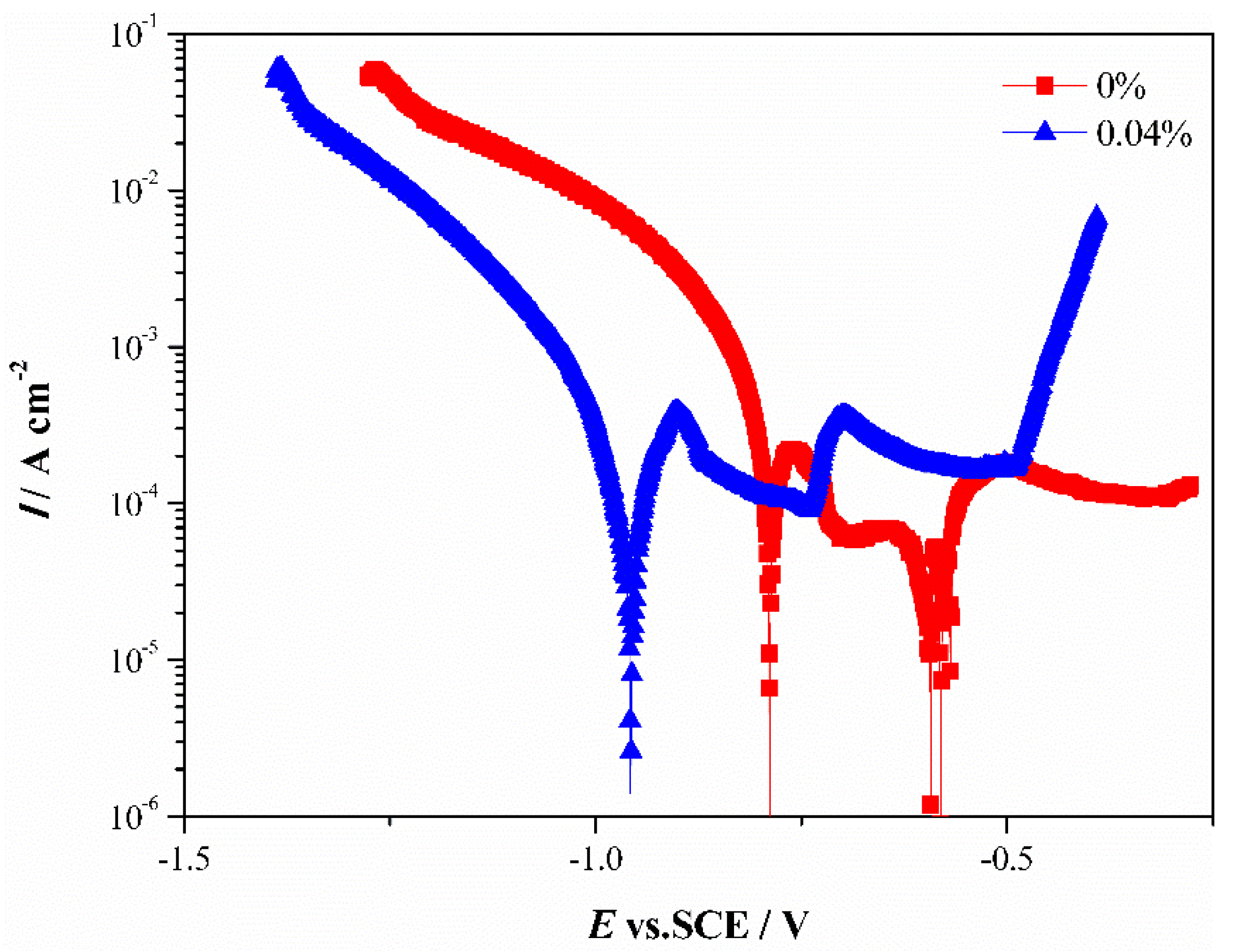
| Sr contents (wt) | Ecorr/V (vs. SCE) | Icorr/(mA·cm−2) |
|---|---|---|
| 0% | −0.79 | 0.475 |
| 0.04% | −0.96 | 8.26 × 10⁻² |
Publisher’s Note: MDPI stays neutral with regard to jurisdictional claims in published maps and institutional affiliations. |
© 2021 by the authors. Licensee MDPI, Basel, Switzerland. This article is an open access article distributed under the terms and conditions of the Creative Commons Attribution (CC BY) license (https://creativecommons.org/licenses/by/4.0/).
Share and Cite
Gao, J.; Gu, W.; Zhang, F.; Geng, H.; Zhong, J.; Yao, L.; Zhao, Z.; Wang, J. Selective Etching of Sr-Modified and Directionally Solidified Industrial Al–Si Eutectic Alloys for Fabricating Fibrous Eutectic Si. Metals 2021, 11, 1974. https://doi.org/10.3390/met11121974
Gao J, Gu W, Zhang F, Geng H, Zhong J, Yao L, Zhao Z, Wang J. Selective Etching of Sr-Modified and Directionally Solidified Industrial Al–Si Eutectic Alloys for Fabricating Fibrous Eutectic Si. Metals. 2021; 11(12):1974. https://doi.org/10.3390/met11121974
Chicago/Turabian StyleGao, Jianjun, Wei Gu, Fenfei Zhang, Haibin Geng, Jianhua Zhong, Ligang Yao, Zhilong Zhao, and Junning Wang. 2021. "Selective Etching of Sr-Modified and Directionally Solidified Industrial Al–Si Eutectic Alloys for Fabricating Fibrous Eutectic Si" Metals 11, no. 12: 1974. https://doi.org/10.3390/met11121974