2. Water Electrolysis
Water electrolysis was developed in the last century mainly to produce hydrogen. Electricity allows for the splitting of water into hydrogen and oxygen then converting electrical energy into chemical energy. Being the hydrogen volume dependent on the electric current, the energy efficiency of the employed system is fundamental.
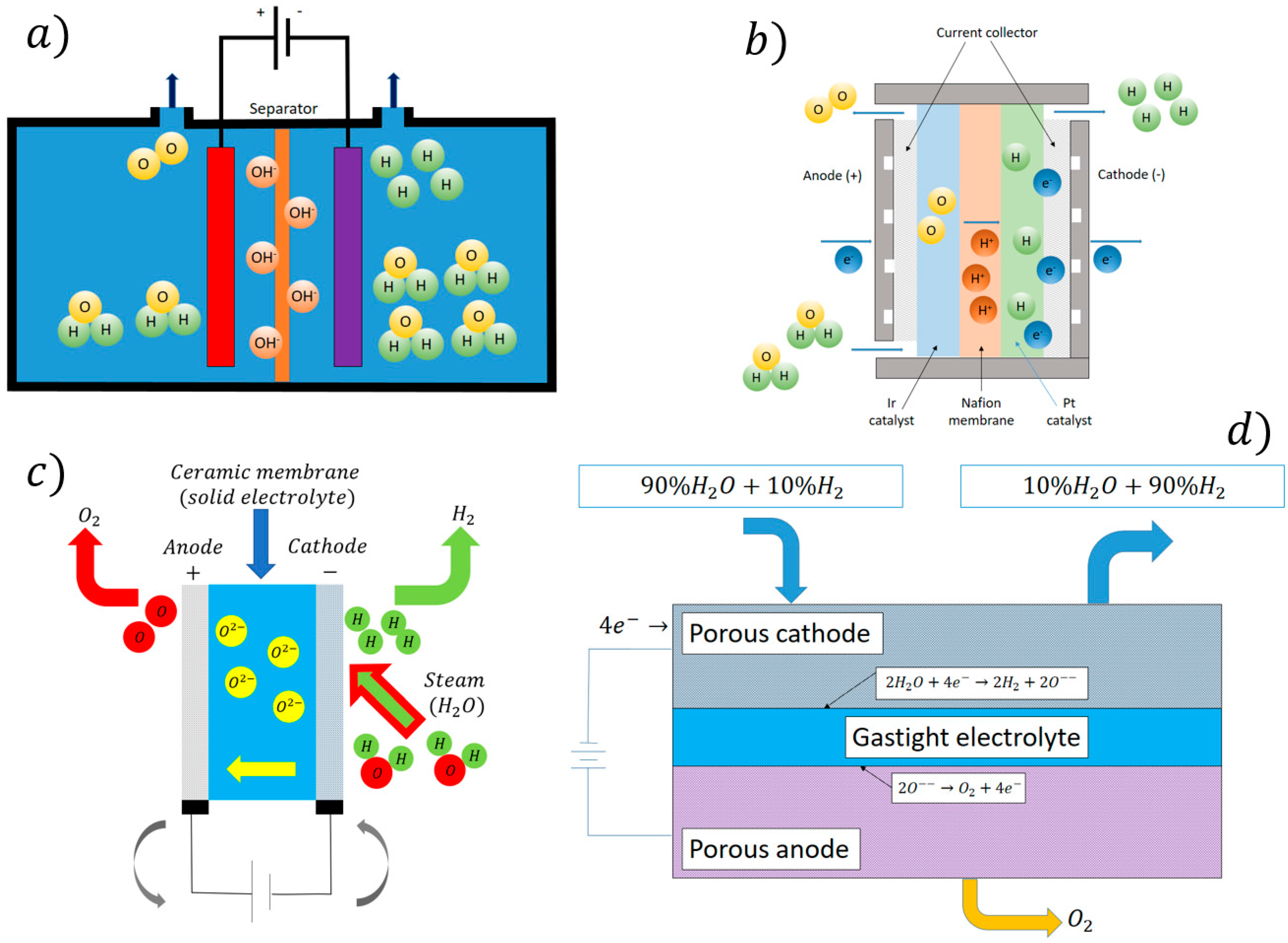
The AEM was the first to be developed. In the alkaline water electrolysis, the nickel-based anode and cathode are submerged in an aqueous KOH or NaOH solution as shown in
Figure 2a.
Water is reduced at the cathode forming hydrogen gas and hydroxide ions OH
−. Hydroxide ions are then decomposed at the anode to form oxygen gas and water. The low-cost electrodes allow for the industrial scaling of this technology [
4]. The separator normally is a Zirfon porous membrane of 500 μm in thickness [
5]. The operating conditions are 70–90 °C at 30 bars with a current density <0.4 A/cm
2.
The PEMEL water electrolysis employs a solid polymer (sulfonated fluoropolymers) electrolyte that is a thin (250 μm thickness) proton-exchange membrane. The schematic of the process is given in
Figure 2b.
Water is supplied to the anode, where water is first decomposed with sufficient electric potential to oxygen gas. H
+ protons cross the membrane, then, once arriving on the cathode surface, it recombines with electrons in order to produce gaseous hydrogen. Iridium and platinum are employed as a catalyst at the anode and cathode respectively. The current collector is made of titanium in order to increase the lifetime of the cell [
6]. The designation ‘PEMEL water electrolysis’ refers to the commercial, traditional acidic PEMEL variant, and the alkaline PEMEL is referred to as anion exchange membrane (AEM) water electrolysis. Alkaline and PEMEL water electrolyzers are readily available, commercialized technologies, while SOEL is the least developed and not widely commercially available [
7].
The schematic of the SOE electrolyzer is shown in
Figure 2c.
AEL and PEMEL electrolysis technologies have operating temperatures below 100 °C. SOEL is based on the electrolysis of steam with operating temperatures in the range 700–1000 °C [
8].
High-Temperature Steam Electrolysis (HTSE) is a new and high-potential instrument for hydrogen production in a clean way. It is based on a reverse fuel cell setting (
Figure 2d).
In the case of steam employment, water dissociation is easier with respect to the case of AEM and PEMEL. This is because part of the required energy is provided by the high temperature of the steam. In general, this solution is suggested for those industrial applications where high-temperature sources are available. This allows HTSE to be very promising from an energy efficiency point of view. In general, as the temperature increases, the global energy efficiency of the process increases.
As a matter of fact, this technology requires less electricity consumption with respect to low-temperature water electrolysis. This is also due to the absolute less internal resistance of the high-temperature electrolysis cells. The cell has classical elements such as anodes, cathodes, and electrolytes. During electrolysis operations, steam and electricity are provided to the porous fuel electrode. This allows the reduction of water molecules for the oxygen ions (O
2−) and hydrogen at the cathode. The electrode, where oxidation reactions take place, is alimented with air. Other complex solutions foresee the employment of different gases or vacuum depending on the cell design. In SOEL, an electrolyte is a thin membrane allowing only oxygen ions to cross. This is a complex cell component that must stop all the hydrogen or different gases. As a function of the cell design, it can work in different ways such as thermo-neutral, endothermic, and exothermic depending on the steam temperature and on the provided electricity [
9].
Not all the provided electricity is employed for the steam electrolysis, in fact, due to important losses, a part of the provided energy is wasted under the formation of heat. So, a large percentage of the global efficiency of the cell is dependent on the balance between the provided energy and the wasted one. The cell works in exothermic conditions once the provided electric energy exceeds the heat required for the water steam splitting. When the cell is working in endothermic conditions, the electrochemical reactions require more heat with respect to the one that is provided by electricity. So, heat is lost, and the cell temperature decreases. In these conditions, additional heat must be provided to the cell.
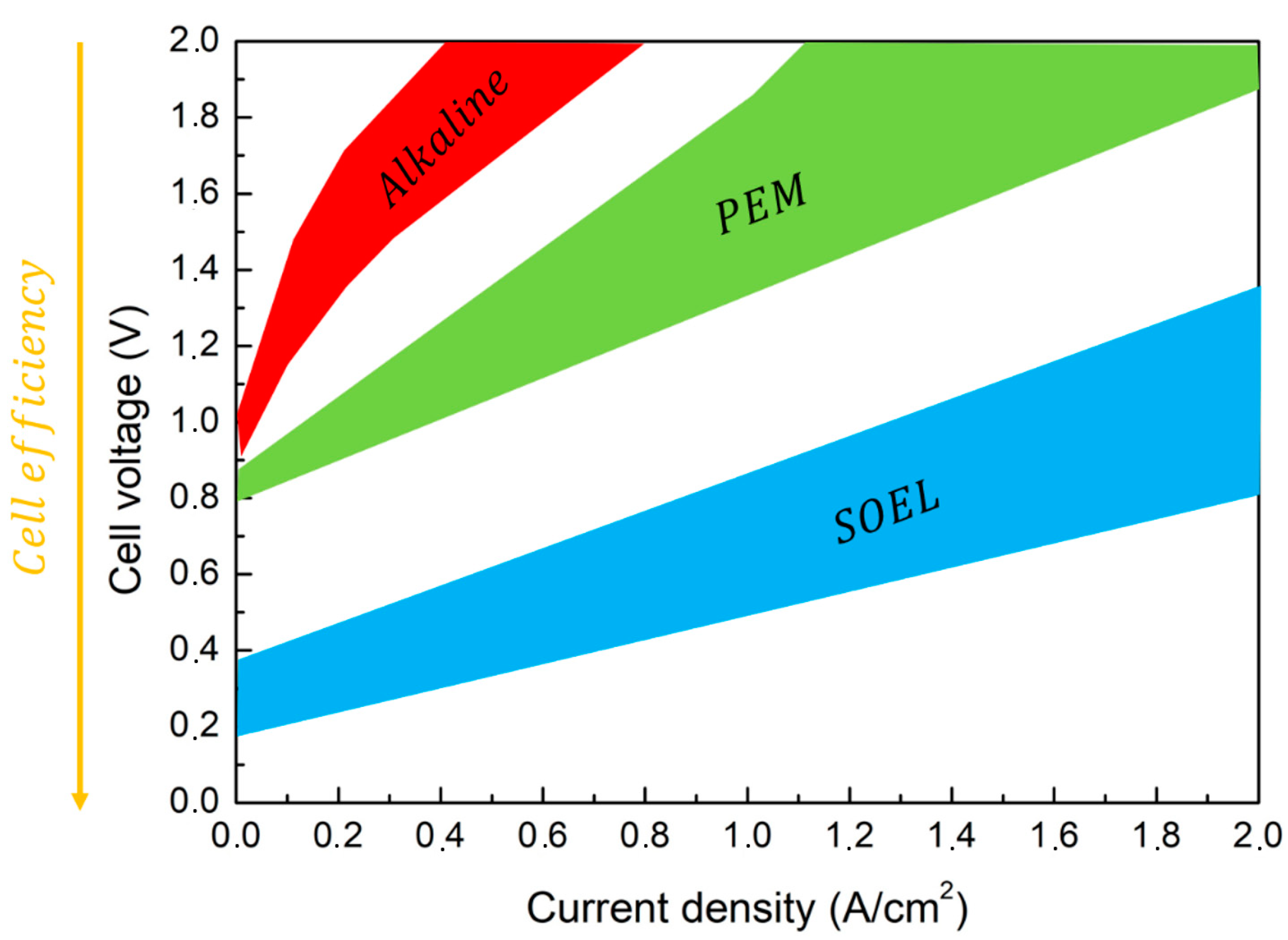
The different cell performances are traditionally evaluated as a function of the electric power that is consumed by the electrochemical reactions for a given hydrogen volume. A good summary is described in
Figure 3 showing the difference among the different electrolyzers.
As a general behavior, water electrolysis for hydrogen production is a high energy-consuming process. This energy is provided mainly by electricity [
10]. The order of electrical power consumption in AEL and PEMEL cells falls in the range 4.4–4.9 kWh/m
3 H
2. Given the heating provided to the HTSE cells, the electric power consumption falls in the range 3.8–3.9 kWh/m
3 H
2 [
11].
As previously mentioned, hydrogen production through water electrolysis can be a completely fossil-free route once the electric power is produced through renewable sources, such as solar and wind. In these conditions, low-temperature electrolysis (LTE) is able to produce hydrogen with a specific electricity consumption (SEC) in the range 50–60 kWh/kg H2.
The steam temperature in HTSE falls in the range 700–1000 °C. It is this condition that allows the SEC to be reduced at the order of 37 kWh/kg H
2 [
3]. In each case, the main limitation to the technology development is the fast degradation of the cell components due to the high temperature and to the environment. Obviously, if the cell temperature is below 700 °C, the cell can reach a durability of around 25,000 h. Anyway, as the temperature decreases, the process efficiency decreases. So, an optimal balance must be done between the steam temperature and the materials consumption. In order for HTSE to become competitive with LTE, the performances should exhibit very high production rates in the order of ~40 mgH
2/cm
2/h or ~−1 A/cm
2. All this is in the case of a reasonable cost due to the fast electrodes and membranes consumption.
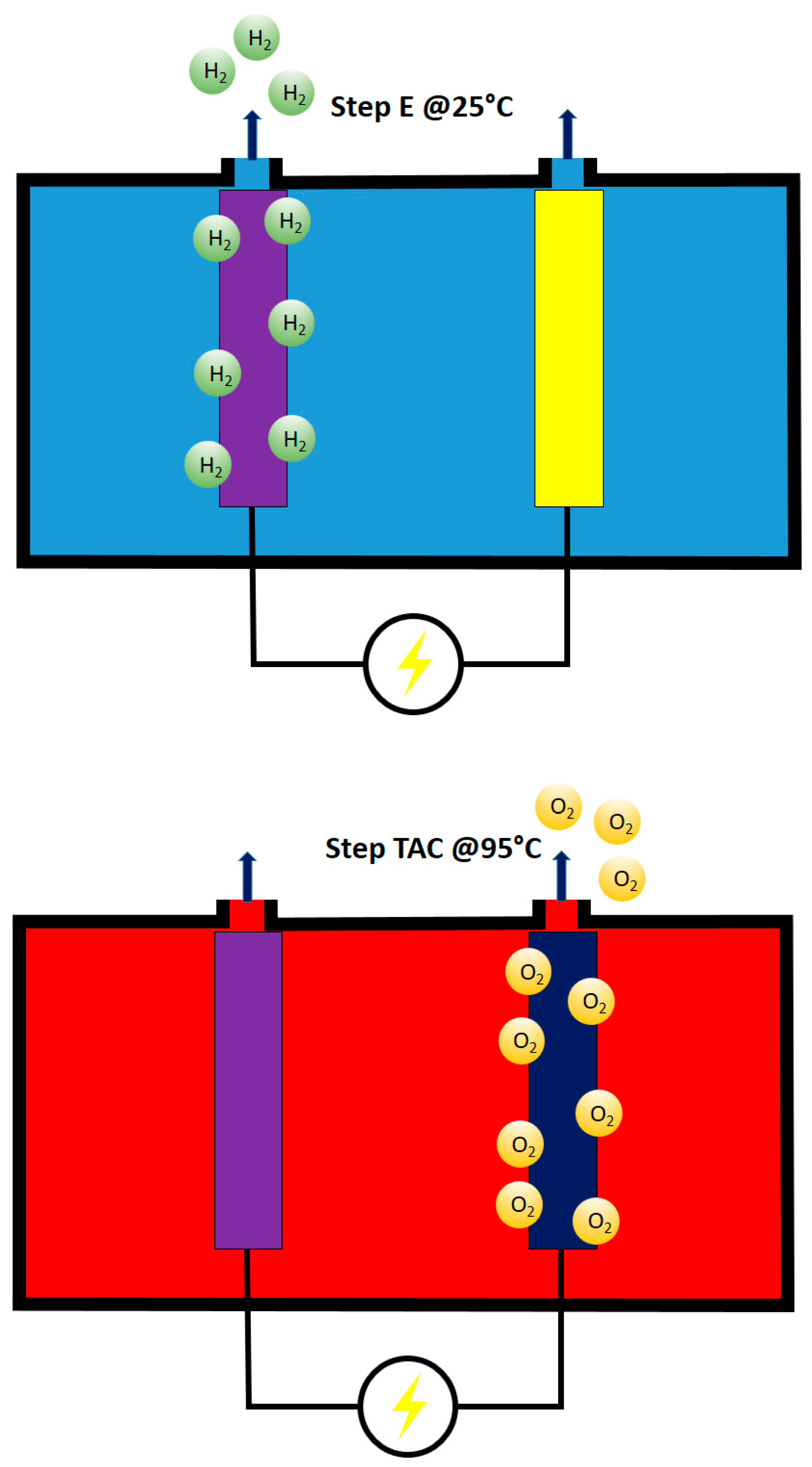
Very recently, a hydrogen production route very similar to electrolysis has been proposed [
12]. This method is known as E-TAC. As with the other water-splitting technologies, the process employs electric power for splitting water into hydrogen and oxygen. The main difference with the previously described technologies is that hydrogen and oxygen gases are produced in two separate and different moments. These are known as an Electrochemical (E) step and a Thermally Activated Chemical (TAC) step (
Figure 4).
Alkaline electrolysis is based on the contemporary oxygen and hydrogen evolution reactions taking place at high temperatures. In this solution, the membrane does not allow the O
2/H
2 crossover. In the case of E-TAC, the water-splitting process takes place in two separate steps. The first electrochemical step, acting at 25 °C, proceeds following the reactions (Equations (1) and (2)):
During this step, only hydrogen bubbles are observed without oxygen production at the anode (in the supplementary material in [
12], very interesting movies, describing the process, can be observed).
The second chemical step, acting at 90 °C, proceeds following the reaction (Equation (3)):
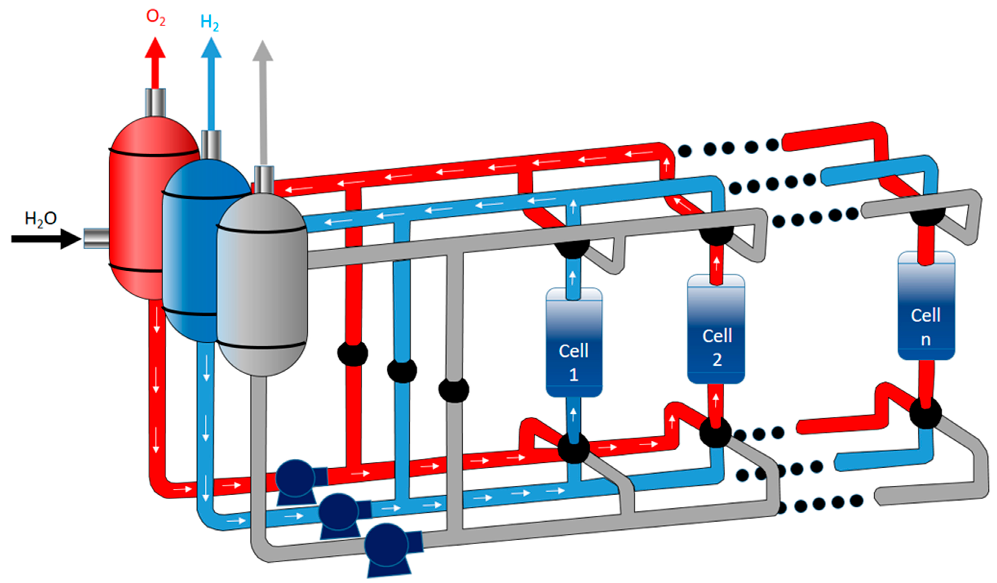
The results belonging to pilot plants show an efficiency close to 95%. The potential for industrial scale-up is envisioned through a multi-cell design. In this design, cold and hot electrolytes are moved from one cell to another in order to regenerate the anode and let gases flow (
Figure 5).
The main advantage of this system is believed to be a membrane-free cell capable of producing hydrogen and oxygen in separate steps. This eliminates all the problems and costs related to membrane-based cells. The lack of a membrane enables high-pressure hydrogen production, potentially exceeding 100 bars. The possibility of operating with low anode potential leads this system to be very competitive in terms of energy balance.
3. Water Electrolysis Fundamentals
As already mentioned, the hydrogen production rate (mol/s) is linearly proportional to the current of the cell (Equation (4)):
where
is the hydrogen production rate (mol/s),
ηF is the Faraday efficiency, also known as the current efficiency,
icell is the current density (A/cm
2),
Acell is the effective cell area (cm
2),
z is the number of moles of electrons transferred in the reaction (for hydrogen,
z = 2),
F is the Faraday constant (9.6485 × 10⁴ C/mol), and
Icell is the stack current (A).
As a general behavior, the anodic and cathodic reactions in acidic media is given by (Equations (5) and (6)):
While in alkaline media (Equations (7) and (8)):
The electrolyte pH is the quantity mainly influencing the number of hydroxide ions and protons that drive the anodic and cathodic reactions. Here, in order to increase the ionic conductivity between the electrodes, strong basics or acids must be employed as electrolytes in order to increase the volume of energy carriers in terms of hydroxides ions and protons. For this reason, once the same electrolyte is used for the anode and for the cathode, the thermodynamic conditions of the water-splitting are driven by the electrolyte pH level.
The energy required for the water decomposition is the enthalpy change of the process, the enthalpy of formation of water, ∆
H. The water electrolysis process is endothermic (∆
H > 0). The free energy of the water-splitting reaction, called Gibbs free energy change ∆
G, must be supplied to the electrodes as electrical energy. The remainder is the thermal energy
Q, which is the product of the process temperature
T and the entropy change Δ
S. These thermodynamic quantities can be written as (Equation (9)):
H is the enthalpy,
G is the Gibbs free energy,
T is the temperature,
S is the entropy, and
Q is the required heat. In constant standard ambient conditions (298.15 K, one-atmosphere pressure), the required electrical work ∆
G is equal to 237.2 kJ/mol (non-spontaneous reaction), and the amount of heat required
Q is equal to 48.6 kJ/mol. Thus, the chemical reaction for water electrolysis can be expressed as (Equation (10)):
Urev is the reversible voltage that is the minimum voltage necessary for the splitting of water. It is directly proportional to the Gibbs free energy change (Equation (11)):
Without the input of thermal energy, the minimum voltage required be-comes the thermoneutral voltage
Utn (Equation (12)):
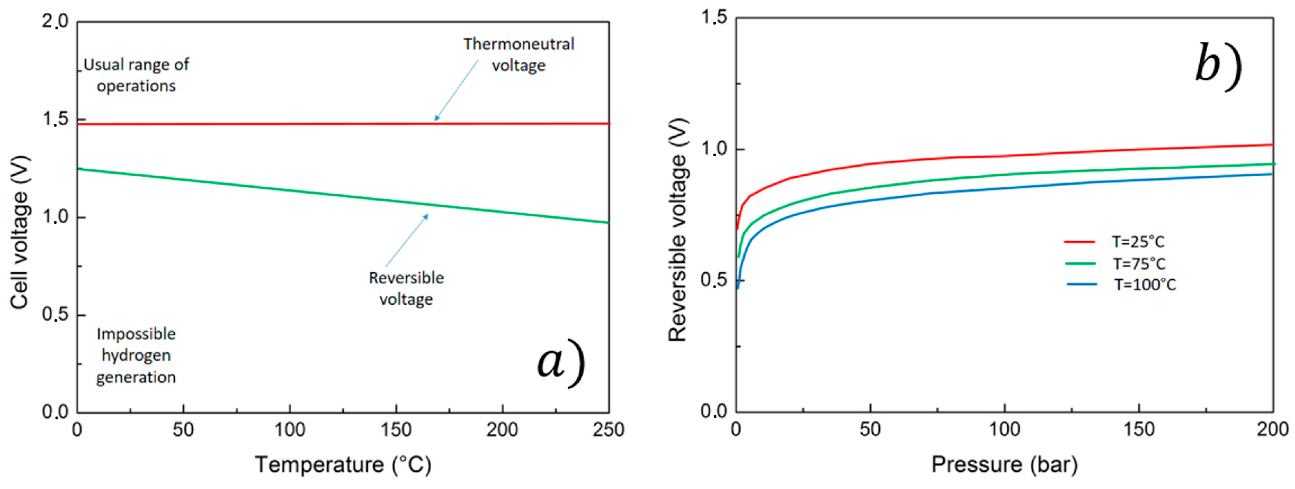
In standard room conditions, the reversible voltage and the thermoneutral voltage result in 1.23 V and 1.48 V, respectively. For commercial water electrolyzers, all energy for the water electrolysis process is provided as electrical energy. Both the reversible voltage and the thermoneutral voltage are thermo-dynamic state functions. These quantities are a function of the cell pressure and temperature, albeit the thermoneutral voltage changes only slightly as a function of temperature and pressure [
13]. The reversible voltage and the thermoneutral voltage are illustrated in
Figure 6a as a function of cell temperature at standard room pressure.
The effect of pressure on reversible voltage is exemplified in
Figure 6b.
An increase in temperature will slightly reduce the overall energy demand ∆
H of an ideal liquid water electrolysis process as the demand for electrical energy ∆
G is more notably reduced than the demand for thermal energy
T∆
S is increased [
14]. Operation at higher temperatures is favorable as heat losses caused by overvoltages can be used to reduce the reversible voltage of water splitting. Thus, the utilization of thermal energy is an essential aspect of energy-efficient water electrolysis processes. The overall energy requirement ∆
H will stay practically constant as a function of pressure in an ideal liquid water electrolysis process. However, a change in pressure will increase the demand for electrical energy ∆
G; for instance, an increase from 0.1 MPa to 10 MPa at a cell temperature of 75 °C will increase the reversible voltage by 9%, but the demand for thermal energy
T∆
S is correspondingly reduced.
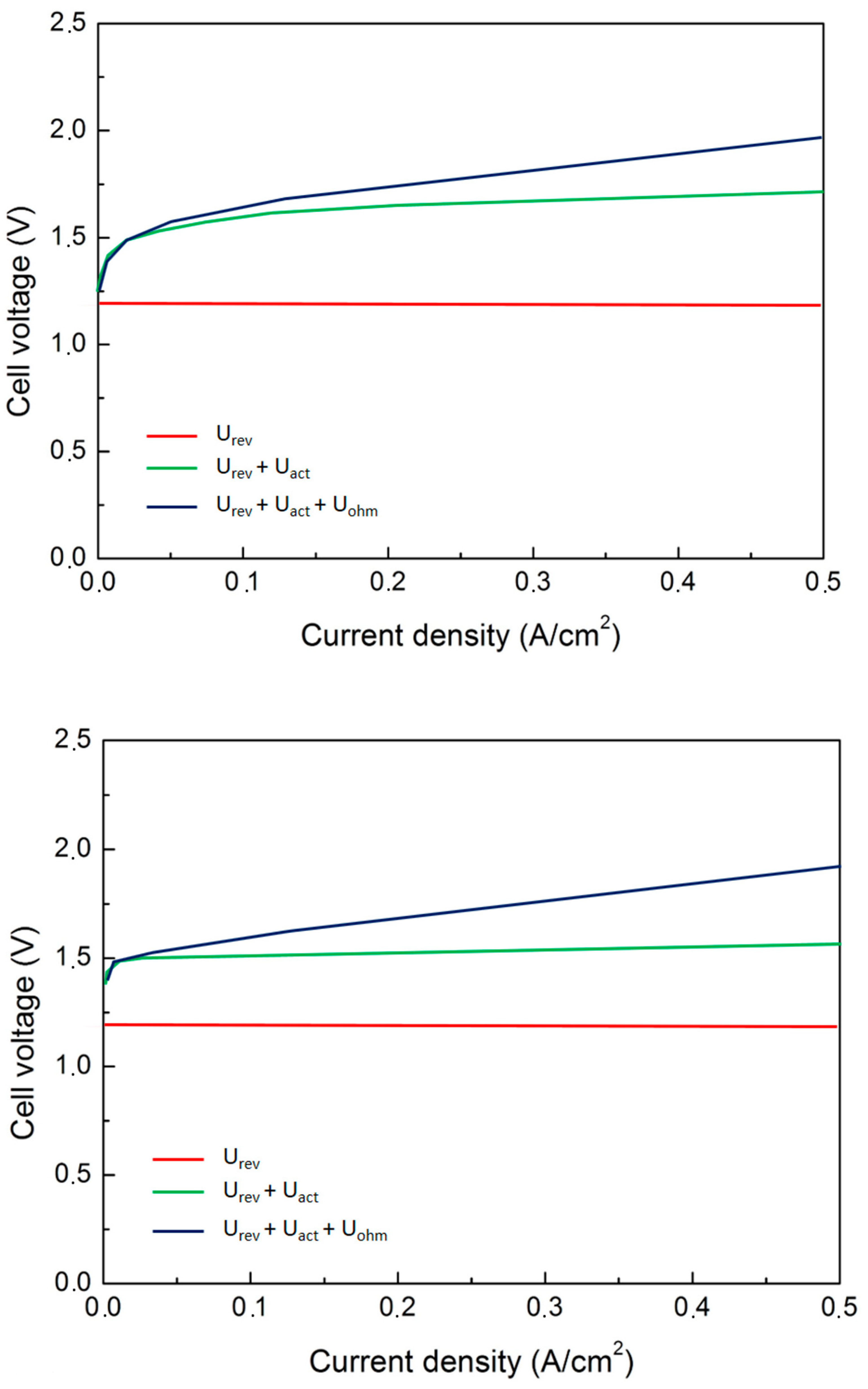
Now, the electrolysis cell voltage results from the sum of the reversible voltage and all the overpotentials developing in the cell through the following equation (Equation (13)):
where
Ucell is the cell voltage,
Urev is the open circuit. The reversible voltage results are a function of temperature and pressure.
Uohm is the overvoltage caused by Ohmic losses in the cell elements,
Uact is the activation overvoltage, and
Ucon is the concentration overvoltage. The current–voltage characteristics of an electrolytic cell can be described by a polarization curve. An example of a polarization curve for AEL and PEMEL water electrolyzer cells is illustrated in
Figure 7.
In the AEL water electrolysis, the Ohmic losses are mainly affected by the ionic conductivity of the liquid electrolyte, the thickness of the electrolyte layer, and the thickness and conductivity of the electrodes [
15]. In the PEMEL water electrolysis, the ionic resistance of the polymeric membrane and the electrical resistance of the separator plates and current collectors are the main contributors to the Ohmic losses. The activation overpotential is caused by the anode and cathode reaction kinetics. The concentration overpotential is caused by mass transfer limitations at high current densities, where the supply of the reactant (water) is not sufficient to support the reaction rate of the production of hydrogen and oxygen gases at the electrode surfaces. The concentration losses are typically negligible for commercial water electrolyzers—especially for AEL electrolyzers—because of the relatively low current densities in the cells. Another non-linear region will appear in the cell polarization curve above the limiting (high) current density if mass transport losses occur. The evidence on the effect of temperature on the AEL performances underlines that all the overvoltages, as the anode activation, the cathode the Ohmic, and the supplied cell ones, increase in the case of the well-known bubble effect. So, as the bubble’s dimensions and volume increase, the overvoltages increase. Now, the bubble’s number, dimension, and volume are directly related to the current density; in addition, as the current density increases, the Ohmic overvoltage linearly increases. It is worth noting that the temperature increase due to an increase in the current density is more pronounced with respect to temperature increase due to the bubble effect. In addition, it should be considered that the power provided to the heater exponentially increases allow current densities levels while it linearly decreases at high current density levels. Power consumption decreases as the cell temperature increases [
16].
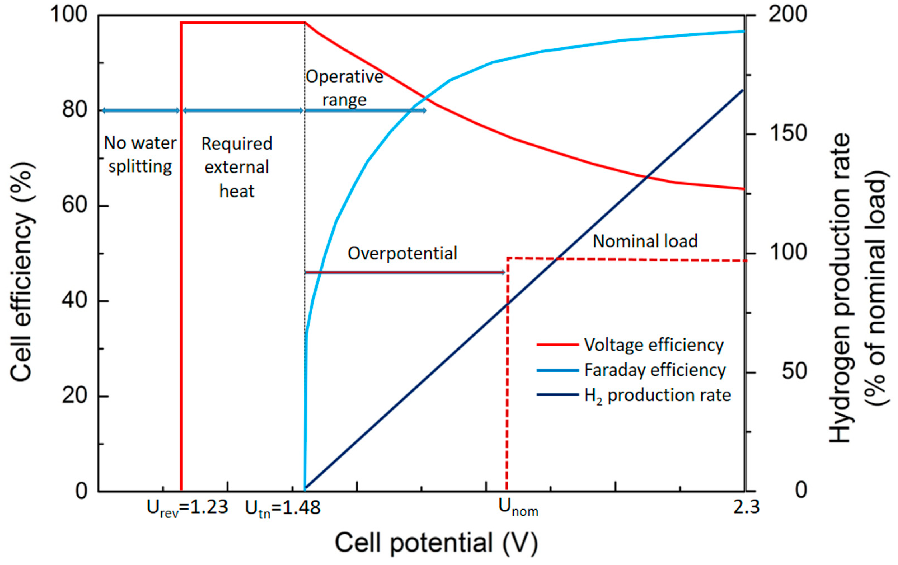
The ideal cell behavior is shown in
Figure 8.
At room temperature and pressure, water decomposition starts at the thermoneutral voltage of 1.48 V. As the cell current increases, the hydrogen production increases. The Faraday efficiency typically approaches unity as cur-rent density is increased towards the nominal current density of the electrolyzer, but at low current densities, the Faraday efficiency may drop considerably.
The voltage efficiency is often used as an indicator of the energy efficiency of water electrolyzers. However, while the voltage efficiency represents the electrical losses in the cell or cell stack, it does not consider the possible stray current flow or gas crossovers over the anode and cathode compartments. The Faraday efficiency, or current efficiency,
ηF is experimentally quantified as the ratio of the ideal hydrogen production rate to the actual hydrogen output from the electrolytic cell (or stack). To include both the voltage and Faraday efficiencies in a single quantity, the definition-specific energy consumption should be used to assess the energy efficiency of a water electrolysis process (Equation (14)):
where
Es is the specific energy consumption,
Istack is the stack current,
Ustack is the stack voltage,
is the hydrogen gas mass flow rate, and
t1 is the inspected time span. Hence, the specific energy consumption describes the amount of energy consumed to produce a mass unit of hydrogen gas. The energy efficiency of a water electrolysis process can be calculated from (Equation (15)):
where
is the higher heating value of hydrogen (39.4 kWh/kg or 3.54 kWh/Nm
3).
Alternatively, the lower heating value of hydrogen (LHV) can be used as a reference (33.3 kWh/kg or 3.00 kWh/Nm3). The difference between the LHV and HHV is the latent heat of condensation. Typically, the HHV value is used as the reference for water electrolysis processes because liquid water is, in the case of alkaline and PEMEL water electrolyzers, usually supplied to the process, and the energy required for evaporation of water must be considered. The specific energy consumption of the water electrolysis process is further affected by the Faraday efficiency, which is non-linear with respect to the current density.
The selection between the currently commercially widely available alkaline and PEMEL technologies will set requirements for the required system components; alkaline technology needs a supply of liquid electrolyte, its controlled circulation, and separation from product gases. Furthermore, alkaline electrolyzer stacks are typically limited in their construction because of the liquid electrolyte supply and gas-liquid transport, which has made 200–300 V the typical stack voltage for industrial electrolyzers. The PEMEL technology avoids the construction limitations of the alkaline stacks, but the requirement for high electric currents (to produce more gases) and the exclusively bipolar construction of PEMEL stacks still set the stack DC currents relatively high compared with the stack DC voltage.
PEMEL water electrolyzers achieve comparable voltage efficiencies at higher current densities, in other words, they have lower cell impedances. Therefore, smaller variations in the instantaneous supply voltage cause greater fluctuations in the supplied current for PEMEL cells. As instantaneous, high variations in current density may have an adverse impact on cell degradation, actions may have to be taken to limit the current slew rate. Cell degradation increases the cell voltage over time, and the increased electrolyzer voltage resulting from degradation should be considered in the system design and operation.
Operating conditions, mainly cell temperature and pressure, affect the reversible voltage and impedance of the electrolytic cell and have an impact on the system efficiency. Increasing the cell temperature is generally beneficial to the cell voltage efficiency, but selected materials will limit the temperature. The cell reversible voltage is also affected by anode and cathode compartment pressures. The resulting change in voltage efficiency from an increase in pressure is comparable with the ideal isothermal compression of hydrogen gas. However, if the surrounding system, such as post-electrolysis synthesis processes or gaseous storage of hydrogen gas, requires elevated pressures, PEMEL electrolyzers may opt to operate at a differential pressure and output only hydrogen gas at elevated pressure, while alkaline electrolyzers are limited to balanced pressure operation. In the PEMEL water electrolysis, the change in hydrogen outlet pressure from 20 bar to 40 bar may result in un-changed electrical energy consumption [
17]. However, an increase in pressure may compromise the control range of the electrolyzer and its specific energy consumption as the gas crossover rate is increased. Furthermore, operating the water electrolyzer in non-optimal conditions may risk the lifetime of the electrolytic cells.
As a matter of fact, the summarized properties of the described systems are listed in
Table 1 [
7].
Water supply and water purification are required to guarantee the normal operation of the water electrolysis process and to preserve the lifetime of the electrolytic cells. In the alkaline water electrolysis, water is consumed from the liquid electrolyte solution, whose concentration must be maintained by an inlet of deionized water. Meanwhile, the PEMEL water electrolysis is electrolysis of deionized water. The conductivity of the inlet water affects the operation of the electrolytic cell, its energy efficiency and aging, and the presence of alkaline electrolyte decreases the gas solubility, which has an impact on the gas crossover. The water supply can also be considered from the system integration point.
Alternative solutions are underlined such as in [
18]. Here, energy-saving yet chlorine-free seawater electrolysis for efficient hydrogen production by a hybrid seawater splitting strategy is proposed. This chemistry consumes the seawater on the cathode to generate H
2 by hydrogen evolution reaction (HER); while the crossover of released OH
– to the anode side supply the hydrazine degradation to harmless H
2 and water with reduced salinity. Beyond the state-of-the-art seawater electrolysis, it enables hydrogen production at ultralow cell voltages but large current densities without chlorine hazards and limiting hydrogen-yielding efficiency. The hybrid seawater electrolyzer (HSE) using NiCo/MXene-based superaerophobichydrophilic and hydrazine-friendly electrodes requires a dramatically lower electricity expense of 2.75 kWh/m
3 H
2 than alkaline seawater electrolyzer (ASE) at industrial-scale current densities. This electrolyzer simultaneously allows fast hydrazine degradation to a rather lower residual while harvesting water with reduced salinity from seawater. On this basis, self-powered seawater electrolysis can be further realized by integrating the HSE into solar or hydrazine fuel cells for better cost-effectiveness and sustainability.
4. Decoupled Electrochemical Water Splitting
Interesting recent progress in water splitting technologies development is the so-called decoupled water splitting. It results in a highly flexible alternative to traditional water electrolysis technologies. During electrochemical water splitting, a redox mediator (
M−) is employed in an oxidation half-reaction that is coupled with the HER. On the other hand, the M half reduction is coupled with the OER (Equations (16)–(21)):
The overall reaction is exactly equivalent to the traditional water-splitting reaction previously described. The mediator (M) is continuously cycled through different oxidation states in a way similar to the well-known redox-flow battery (RFB) or a solid-state battery. Obviously, this behavior is dependent on its physical state.
As in traditional water-splitting technologies, inputs are water and electricity while the products are hydrogen and oxygen gases [
19]. In the case of decoupled water splitting, pH is related to the electrolyte (as in the case of traditional electrolysis) but also to the current provided during the independent decoupled reactions.
The previous equations can be modified slightly for mediators that also up-take and release protons during operation (Equations (22)–(27)):
The overall reaction is the same as the overall water splitting reaction even if the system is proton balanced. In the case of alkaline electrolytes, the reactions are similar; the only difference is that balancing is performed by hydroxide ions.
The employment of the mediator allows for the separation of the hydrogen and oxygen evolution reactions in space and time. So, the benefits are mainly due to the possibility of controlling separately the steps with increased efficiency. Other positive aspects are represented by the possibility of employing low-cost electrolyzers; favoring the integration with renewable sources; improving the safety conditions of all the processes mainly related to the risks of explosion.
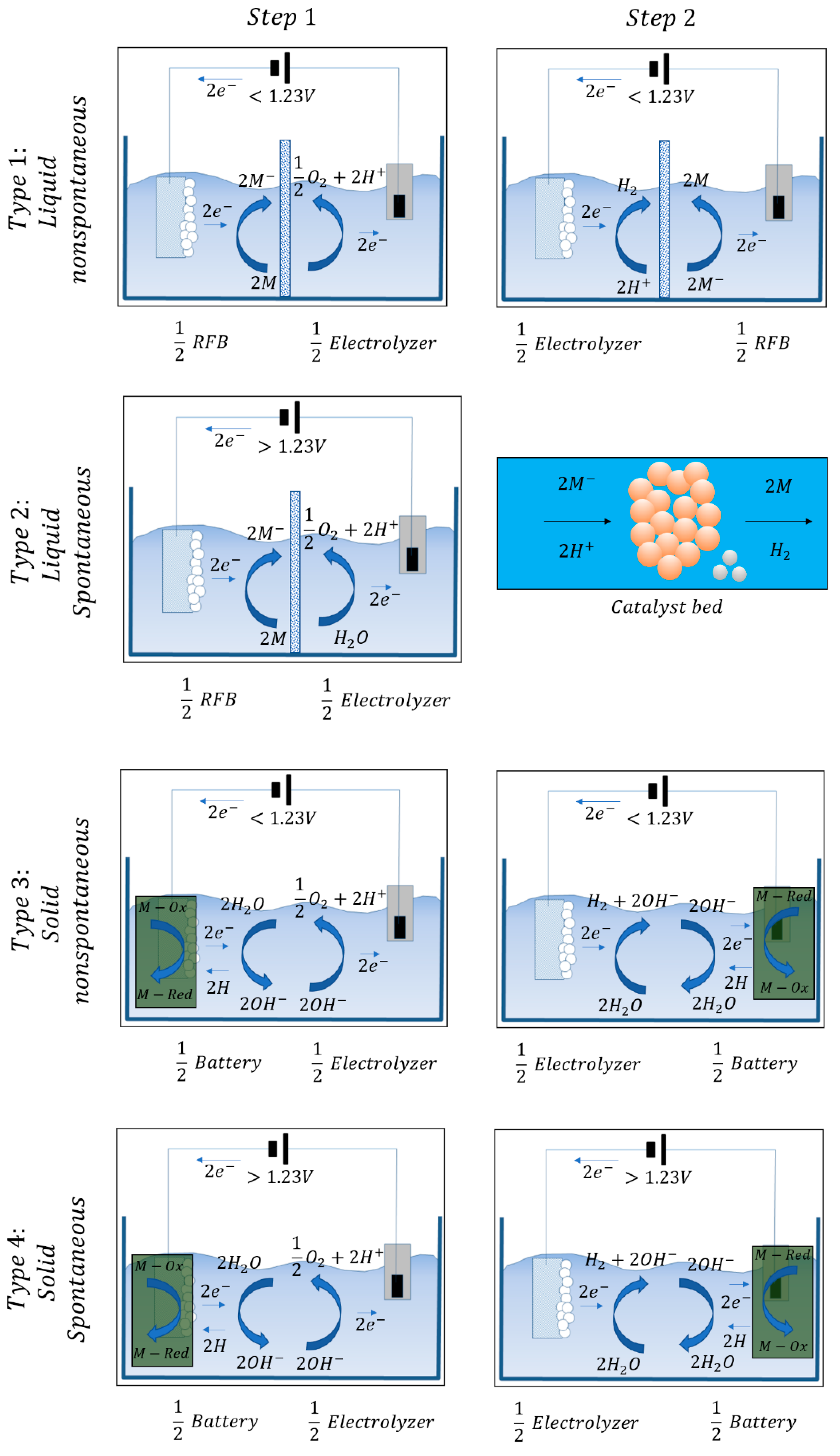
Given all those aspects, the decoupled water splitting systems are grouped into four classes depending on the physic conditions of the mediator, and on the input of the electricity (
Figure 9).
The type 1 system is liquid mediated. This system consists of an RFB half-cell and an electrolysis half-cell. The mediator is contained in the electrolyte, it is reduced during step 1 (left) then, it is sent to the second cell. Here the mediator is re-oxidized. On the contrary, the electrode can be changed for the half-cell electrolysis by driving the reactions through a polarity opposite with respect to step 1.
In this kind of cell, the separator is employed in order to avoid the mixing of the mediator and the electrolysis products. Another kind of cell is represented by a situation where the second step evolves spontaneously (Type 2). Here the cell is composed of an RFB half-cell and an electrolysis half-cell with a catalyst bed. Here, HER acts spontaneously then, external input is not necessary.
Another type of decoupled water splitting is a solid-based technology based on two non-spontaneous steps (Type 3). This kind of cell employs only one electrode that is coupled alternatively to another electrode for the development of HER or OER in alternative ways. The basic construction of this solution is, for driving the two steps, an electrolysis half-cell and a battery half-cell.
A different intermediate solution is the employment of a solid mediated system with only one spontaneous step (Type 4). The basic design is very similar to Type 3. In this solution, the second cell is not provided with electricity.
The continuous development of these systems led to the possibility of employing non-precious catalysts arriving to be competitive with the underdeveloped best PEM cells. It is also possible to employ low-cost membranes depending on the chosen configuration.
5. Water Purification
Water to be split during electrolysis must respond to many compositional requirements. These are standardized by the American Society for Testing and Materials (ASTM) Type II deionized (DI) water (resistivity 41 MΩ cm) while ASTM Type I DI water (410 MΩ cm) is preferred. ASTM defines Type II water, as required in commercial electrolyzers, as having a resistivity of 41 MΩ cm, sodium, and chloride content <5 μg L−1 and <50 ppb of total organic carbon (TOC).
The requirements needed by the water to be split in Alkaline electrolyzers are less stringent if compared to those needed for PEM. Anyway, as the water purity increases, the cell stability improves. Many techniques are available in order to reach such purity levels. The main applied ones are reverse osmosis (RO), multi-stage flash distillation (MSF), electrodialysis (ED), multiple-effect distillation (MED) to desalinate water. Sometimes they are coupled with an ion exchange or electrodeionization (EDI) for further improvement of the water quality.
In the case of seawater electrolysis, operating and capital costs must be seriously considered because of the equipment consumption depending on the starting water quality [
20].
In the recent past, many developments have to reach toward the optimization of electrodes and catalysts for the OER in alkaline media of the seawater. The best conditions are underlined in the order of (4300 mA cm−2) at the typical seawater pH (8). Now, seawater is very rich in borates and carbonites; the presence of these compounds limits high current densities. This limit can be overcome through the addition of additives such as KOH. All these additives led to an increase in the conductivity as the concentration increased. Obviously, it must be taken into account that the increase in additives concentration leads to a variation in the water pH. Strong variations in the pH impact the durability and stability of the electrodes. Other problems to be faced are eventual presences of other kinds of impurities such as various dimensions particles, ions, bacteria, microbes, all impacting on the system stability and long-term durability.
Much progress has been done in the recent past on desalinization through seawater reverse osmosis (SWRO). The improvements are mainly due to the development of highly resistant, stable, and efficient membranes, highly efficient energy recovery devices, and process optimization of reverse osmosis (RO) systems. All this progress led to the reduction in electricity consumption as well as to an important drop in operating costs. At the present time, the energy requirement of SWRO desalination plants has decreased from 9–10 kWh m−3 to <3 kWh m−3.
A schematic of a typical desalinization plant coupled with a PEM electrolyzer is shown in
Figure 10.
The PEM electrolysis plant consists of the electrolyzer stacks and the mechanical and electrical balance of plant (BoP) components. The electrical BoP consists of the AC to DC rectifier for converting grid electricity while the mechanical BoP consists of other auxiliary components such as pumps, heat exchangers, temperature swing adsorption (TSA) subsystem, and most importantly a deionizer (DI) system.
The SWRO plant contains the RO unit which uses a membrane barrier and pumping energy to separate salts from saline water. Using high-pressure pumps, water is forced through semi-permeable membranes that have a dense separation layer (thin-film composite membrane) allowing the passage of pure water molecules while rejecting dissolved salts and other impurities. In addition, in order to control RO membrane (bio)fouling and scaling, the SWRO system necessitates physical (e.g., dual media, sediment and carbon filters or low-pressure membranes, such as ultrafiltration) and chemical (e.g., coagulant polymer, antiscalant, acid, chlorination/dechlorination) pre-treatment steps with variable complexity depending on raw feed water quality. A combination of these filters provides a broad spectrum of reduction.
There are several RO pre-treatment designs that could be adopted depending on the quality of water needed. The desalination unit consists of a double-pass RO system designed to attain the high purity of water required by the PEM electrolyzer. The SWRO-PEM coupled system could be located in coastal regions with intense solar irradiation and/or wind energy available to produce renewable electricity via photovoltaic cells, wind turbines, or even offshore structures if hydrogen supply for shipping for example was desired.
6. Efficient Hydrogen Production
The classically employed electrocatalysts for both the hydrogen evolution reaction (HER) and oxygen evolution reaction (OER) are precious metals such as platinum (Pt), and ruthenium (Ru) as well as their compounds. Obviously, these are very expensive materials; for this reason, electrolysis development limited in the past the large-scale industrial applications of these technologies.
For these reasons, technological and scientific research focused on the development of less expensive non-precious metals-based catalysts HER and OER.
The best alternatives have been recognized in metal-organic frameworks (MOFs) composites and transition-metal-based compounds such as metal oxides, hydroxides, sulfides, phosphides, nitrides, and selenides with high electrocatalytic properties for the development of HER and OER [
21].
All the present efforts are devoted to increasing the efficiency of these non-precious materials catalysts in order to reduce the electric power required for hydrogen production.
Being electrochemical water splitting is one of the most environmentally friendly approaches used to produce hydrogen because it involves no carbon footprint. The half-cell reactions (HER and OER) occurring at cathode and anode, respectively; it must be fed by renewable sources. The final electrochemical decomposition of H
2O into H
2 and O
2 (by-product) is shown in (Equations (28) and (29)):
so, the global reaction will be (Equation (30)):
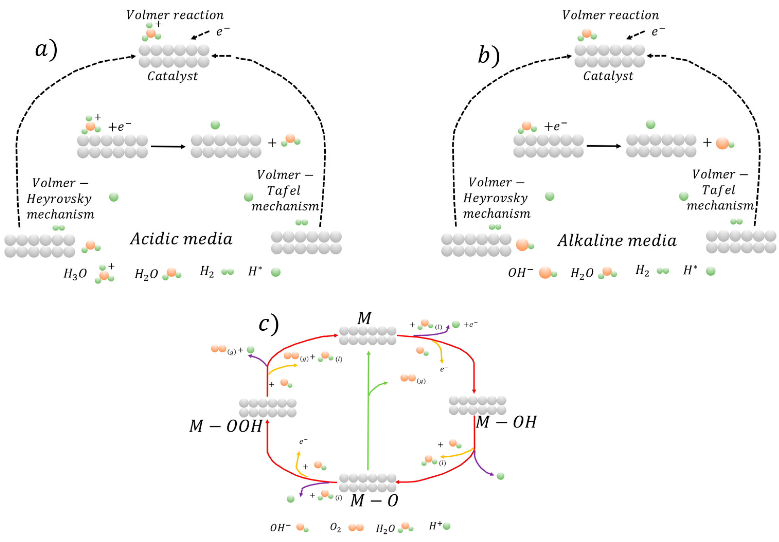
Hydrogen is produced during the development of HER representing one of the half-reactions in the overall electrochemical water splitting process. Obviously, only limited elements are favorable for efficient hydrogen production during HER. They are basically efficient for favoring the well-known fundamental mechanisms of the HER catalysis. These mechanisms are the Volmer-Heyrovsky and the Volmer-Tafel ones. The evolution of these mechanisms in acidic media is schematically shown in
Figure 11a.
The schematic of the evolution of the mechanisms in neutral and alkaline media is shown in
Figure 11b.
In detail, the Volmer mechanism governs the primary step of HER during which the beginning of the transfer of the electrons takes place. Firstly, the H+ (H3O+) combines with an electron to form H* deposited/adsorbed on the electrode surface. The adsorbed H* is then removed/desorbed by two paths to form H2. At this stage, the first desorption step takes place. This is known as the Heyrovsky mechanism reaction during which the H* atom in an adsorbed state merges with a free H+/e− couple from H2. The final desorption step is governed by the Tafel reaction mechanism during which two adsorbed H* combine to produce H2.
By analyzing these fundamental mechanisms, in the case of high Tafel slopes, the Volmer reaction results in the rate-determining step. This indicates that the adsorption of hydrogen on the catalyst surface under low H coverage acts. Obviously, the electrode kinetics mechanisms during HER are strongly dependent on the solution pH. This is because, chemically, electron transfer is driven by the catalytic activity at the electrode surface. As a consequence, the focus must be on the evolution of the catalytic mechanism in different media.
The second half-reaction of water splitting is the oxygen evolution reaction (OER). It takes place at the anode electrode surface. The main difference with respect to the HER is that this reaction evolves through a four-electron transfer.
With respect to HER, OER requires higher overpotentials. This aspect is responsible for the strict matters related to the overall energy behavior and efficiency of the electrolysis processes. The main intermediate products of OER mechanisms are O*, OH*, and OOH*. Due to the nature of these products, the oxygen evolution follows different routes depending on the solution media. The main aspect of ORER is that, here, OH− is absent in acidic solution. For this reason, the metal (M) reacts with water producing MOH. Then, it reacts continuously with electrons by transforming into MO.
MO and oxygen can be produced via two different mechanisms: in the first, two MO combine in order to produce oxygen directly; in the second, MO reacts continuously with oxygen by forming the intermediate species MOOH, later, MOOH forms O2.
The decomposition of MOOH forming O
2 is shown in
Figure 11c.
According to the Sabatier principle, the adsorption phenomenon is high pronounced to produce desorption; so, it is necessary to employ catalysts with the moderate binding capability to drive the whole process. In this view, when catalysts have weak bonding with O, the intermediate species OH* does not evolve easily into OOH*. It is believed that the best catalytic performance can be reached once the bonding of O acts in moderate conditions.
The best way to produce clean hydrogen is the employment of renewable power sources such as wind, solar, and biomass. Anyway, at the present time, only 4% of the consumed hydrogen is produced via this route. The remaining percentage is still related to technologies different from water electrolysis. The main problem is related to the origin of power and to the issues connected with the consumption of the electrolysis cells components.
Now, from a chemical point of view, the minimum energy needed for the water-splitting is the Gibbs free energy related to the needed voltage at a given temperature and pressure. In order to have efficient water splitting, the catalytic behavior during both OER and HER mast be kinetically increased for high overall electrolysis efficiency. At the present time, precious metals such as platinum are the best choices for efficient water splitting. However, much progress has been done in the recent past with respect to the development of catalysts based on less expensive materials. The main route is the replacement of precious metals with non-metal ones especially the transition materials.
Several transition metals compounds result in a very effective application in alkaline water electrolysis (AWE). They are mainly based on Fe, Mn, Co, and Ni-based, including their oxides resulting very efficiently during HER and OER half-cell reactions in water splitting. The main routes toward their large utilization are the improvement of electrical conductivity, the increased stability in different environments and media, the possibility of designing hybrid solutions by coupling such compounds with carbon-based materials.
More serious problems are faced during the development of water steam electrolysis. In fact, the very high temperature of the steam (in the order of 1000 °C) leads to fast degradation of the cell components, in particular, electrodes. In addition, such high-temperature conditions lead to the high instability of the electrocatalysts. In addition, critical issues are represented by ionic conductivity, electronic conductivity, and catalytic conductivity in SOEL. One of the primary solutions is the expansion of the surfaces of the electrode in order to reduce excessive heating. Costs can be reduced by deeply employing non-precious metals as catalysts. The cell duration can be increased by reducing the overpotential well as improving the stability of the catalysts.
Being the more recently developed, non-precious materials catalysts research for PEMEL cells is at the beginning. The main problem is that the stability of catalysts into acidic media is very crucial. The mainly employed materials for HER in acidic media are the oxides of transitional metals such as NbC, SnO2, Ta2O5, TiO2, WC, and TiC. The field is still very open because it is very difficult to substitute precious metals catalysts for the oxygen evolution reaction in PEMEL cells.
Other alternative solutions are represented by the employment of MOF electrocatalysts for OER and HER. They have large potentials because of their large surface area, optimal physiochemical properties, and porous structures.
7. Steel Manufacturing with Renewables Integration
During the direct reduction of iron oxides through hydrogen, water vapor is produced instead of carbon dioxide of the traditional ironmaking and steelmaking routes [
22,
23]. Then the water vapor can be separated and condensed or employed as input in the electrolyzers for water splitting. In this scenario, the only produced carbon dioxide is the one belonging to the power to be employed for the electrolysis operations. As above mentioned, H
2 is currently mainly produced from fossil sources (natural gas, coal, oil), by biomass gasification, and from non-carbon sources, such as water electrolysis [
24]. Once fossil sources are employed, as in the case of natural gas or methane, the generated carbon dioxide must be captured and stored with largely increased costs. If green power is employed, the consumed power is in the order of ~5 kWh/m
3 of H
2. It is believed that further developments of the different technologies will lead to a remarkable reduction in consumption [
25].
Hydrogen has large potentials for the direct reduction of iron ores. Obviously, the best solution is to reduce iron oxides through hydrogen produced via water electrolysis. In this way, it is estimated that the overall process can lead to carbon dioxide emissions in the order of 300 kg/t HRC.
The main employed direct reduction reactors in the world steel industry are based on the MIDREX or HYL processes. Here the dynamic control of the different transformations is optimal for the direct reduction through hydrogen. Obviously, many issues are related to the temperature and pressure in the reactor in terms of safety, product quality, and efficiency of the whole reduction process. Another fundamental aspect is represented by the metallization degree and by the presence of carbon in the reduced iron [
1].
Generally, hydrogen can be employed as the only reductant gas in these king of plants as well as mixed with different percentages of natural gas. By considering the MIDREX
® Plant, in the case of H
2 addition, one-third of the required natural gas can be substituted. For example, 60,000 Nm
3/h of H
2 can be substituted for approximately 20,000 Nm
3/h of natural gas in a 2.0 Mtpy plant, which represents approximately 30% of the total natural gas consumption. MIDREX
® Plants generally employ three different ratios of H
2 and CO. Most use natural gas and a standard MIDREX
® Reformer that produces a reducing gas with 55% H
2 and 36% CO (H
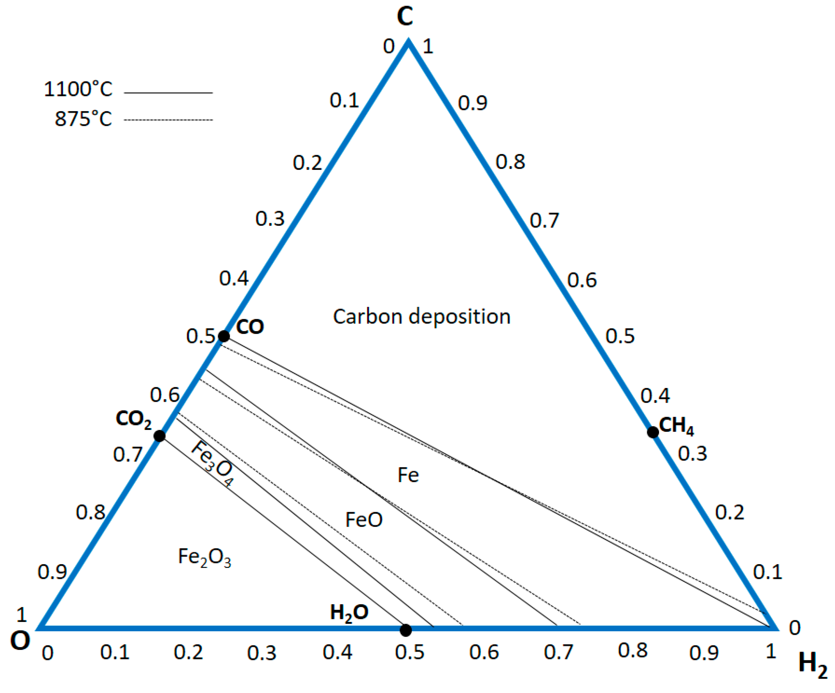
2/CO of 1.5). As above mentioned, hydrogen is very volatile, so the reactor pressure is fundamental. The equilibrium diagram for the reforming processes is shown in
Figure 12.
The hematite reduction act through the following reactions (Equations (31)–(36)):
The FMO MIDREX® Plant in Venezuela is designed with a steam reformer, and H2/CO can vary from 3.3 to 3.8. There are six MIDREX® Modules that utilize gas made from coal, and these have hydrogen to CO ratios from 0.37 to 0.56. Thus, the MIDREX® Process has successfully produced DRI at H2/CO ratios from 0.37 to 3.8. In these plants, 100% of pure hydrogen can also be employed. However, in the case of MIDREX, the reactor configuration does not change if natural gas or hydrogen is used as a reductant. H2 input gas is generated external to the process and there is no reformer. With this design, a gas heater is employed to heat the gas to the required temperature. In the practice, the reducing gas H2 content is about 90%, with the balance CO, CO2, H2O, and CH4.
These last gases come from the addition of natural gas for temperature control and carbon addition in order to tune the needed carbon percentage in the reduced iron. Since H2 is converted to H2O and condensed in the top gas scrubber, no CO2 removal system is necessary. With this plant setting, hydrogen consumption is approximately 550 Nm3/t DRI. Additionally, up to 250 Nm3/t DRI of H2 or other environmentally friendly heat sources such as waste heat, electricity, and/or natural gas are required as fuel for the reduction gas heater. With this process, CO2 emissions could be reduced up to 80% vs. the BF/BOF steelmaking route. There are a number of considerations for the MIDREX H2™ Process, the first of which is temperature. With these high hydrogen percentages, the DRI is deeply cooled. So, natural gas is necessary to sustain the needed temperature levels. According to Midrex indications, the addition of natural gas at a rate of 50 Nm3/t DRI should accomplish this.
As mentioned above, the other crucial aspect is the iron carburizing. The vast majority of DRI is used in EAFs for further processing. EAF steelmaking practices today generally employs carbon added either in metallic charge materials such as DRI, HBI, and pig iron or as pure carbon. Burning this carbon with injected oxygen creates significant heat which reduces electricity consumption and enables faster melting. Since pig iron is made from BF hot metal that is saturated with carbon, it contains 4–4.5 percent carbon. DRI can have 1–4.5 percent carbon depending on the process, reducing gas used, and the way the DR plant is operated.
In the case of hydrogen produced via electrolysis, a crucial aspect is also represented by the location of electrolysis plants to produce hydrogen because this is the most electricity-consuming section of the integrated plant. To give an idea of electricity needed, for fossil-free electricity in the electric arc furnace, the amount of electricity is only about 0.5 MWh/ton liquid steel while the electrolysis consumes more than 2.5 MWh/ton liquid steel. For an energy system based on renewable and intermittent electricity, there is a need for balancing power, and hydrogen storage can play an important part.
The simplified schematic of the different sections of the analyses is shown in
Figure 13.
Energy is required by the DRI pre-heating, for the hydrogen pre-heating and compression before storage; this energy is very low if compared to the one required by the main sections of the plant.
In order to produce one ton of sponge iron through HDRI, 49 kg (545 Nm3) of hydrogen is necessary.
Electrolysis is a modular technology where a big facility would consist of several parallel electrolysis stacks. The capacity of the current biggest stacks is approximately 600 Nm3 H2 per hour. The electricity consumption per Nm3 hydrogen differs between 4.6–5.6 kWh/Nm3, depending on the technology (alkaline electrolysis or PEM) with an expected decrease of approximately 0.2–0.4 kWh/Nm3 for both technologies in the future due to technology and efficiency improvements (HYBRIT 2018). The 545 Nm3 H2 required for the production of one-ton sponge iron needs approximately 2.5–3 MWhe (de-pending on the electrolysis technology) for the hydrogen production.
Depending on the energy-saving requirements, electrolysis facility can either be placed close to the electricity generation e.g., close to a wind farm, and the hydrogen can then be transported in pipes to the DRI plant, or it could be located close to the plant, given that the conditions of the local energy system are right. One option is also to decentralize the system and locate the electrolyzers separately close to several different power production sites [
26]. First of all, the power and electricity requirements depend on the DRI capacity. In order to produce one million tons of sponge iron, 2.7 TWh are required to correspond to 341 MW. These requirements increase to 8.2 TWh and 1022 MW for a three million-ton facility. At the moment this is the maximum size of the installed DRI plants. If a capacity of 5 million tons is reached, the requirement is 13.6 TWh and 1700 MW. In the case of hydrogen storage, the capacity of the electrolyzer must be increased. The optimal solution is believed to be the location of the electrolyzer plant directly connected with the renewables.
A very recent study investigates the integration of water electrolysis technologies in fossil-free steelmaking via the direct reduction of iron ore followed by processing in an electric arc furnace (EAF) with very broad and deep analyses of all the components. Hydrogen (H
2) production via low or high-temperature electrolysis (LTE and HTE) is considered for the production of carbon-free direct reduced iron (DRI) [
3,
27,
28]. Producing carbon-free DRI with H
2 produced via LTE is probably the most straightforward route to fossil-free steel. HTE is attractive due to its high efficiency, given that steam is available, but is a much less proven technology than LTE [
29]. Anyway, in all those situations where high-temperature sources and steam are available, THE is very efficient. Obviously, the performance and the durability of these high-temperature cells are fundamental for the large diffusion in the steel industry.
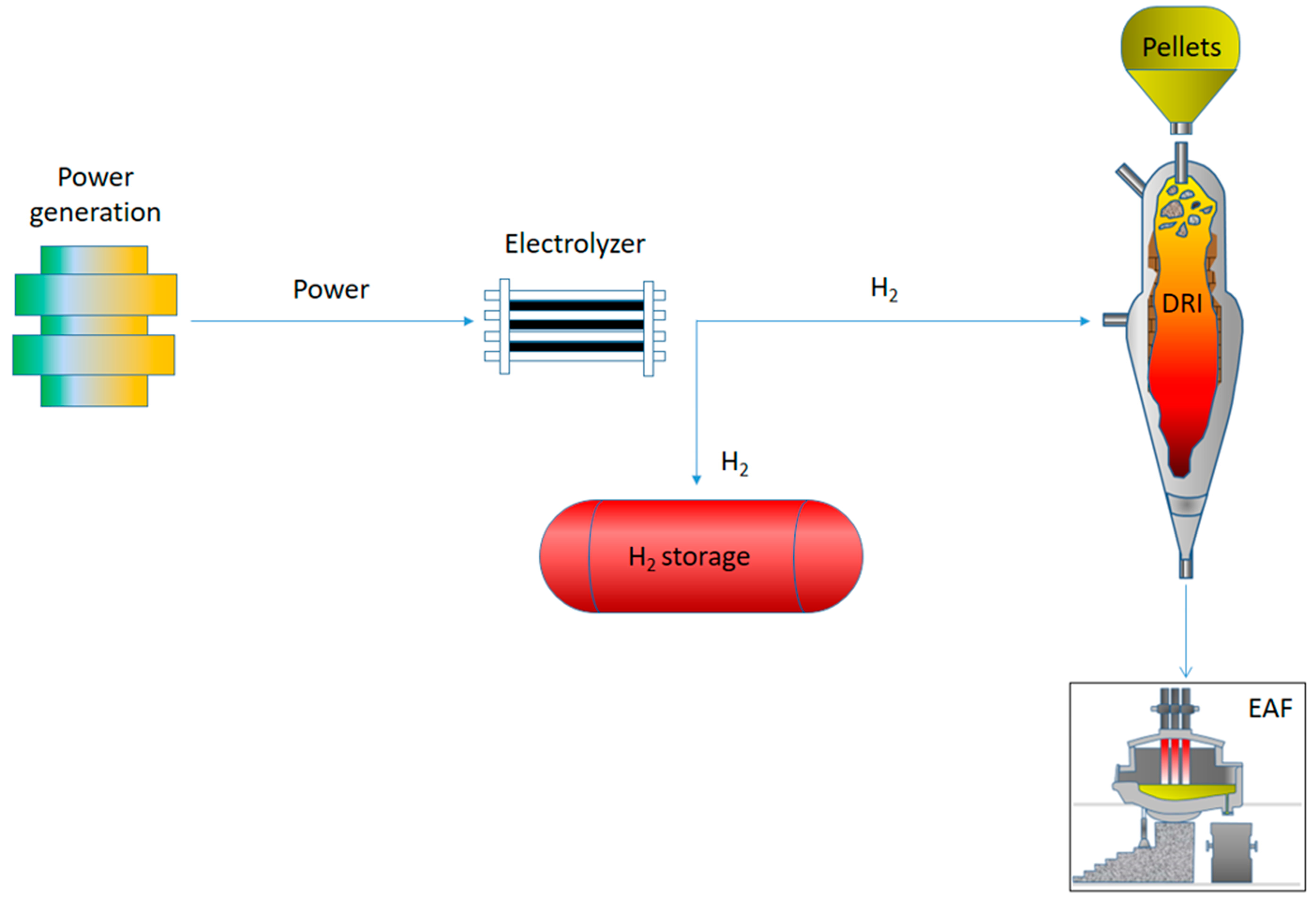
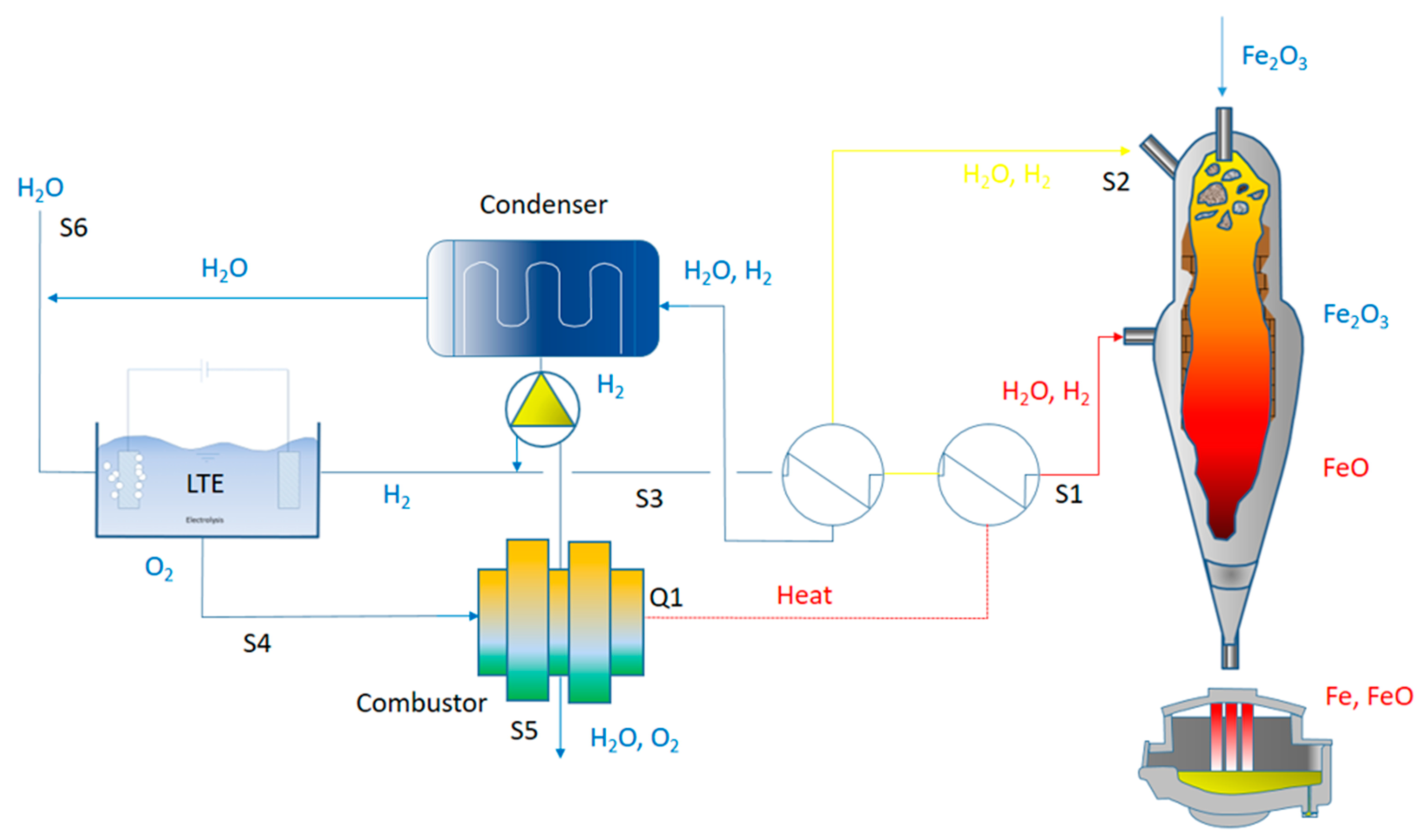
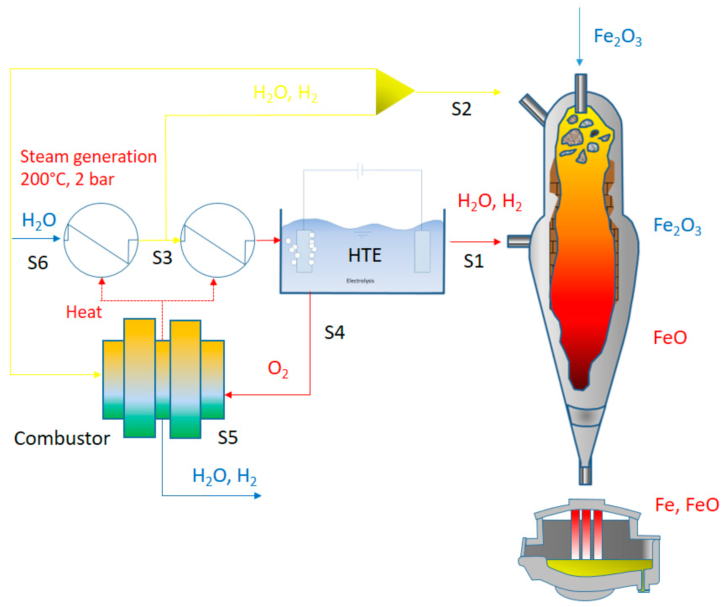
The schematic of the DRI plant integrated with LTE and HTE is shown in
Figure 14.
In all the described solutions, hydrogen is sent to the reactor at a temperature around 900 °C. By employing LTE, hydrogen must be pre-heated through heat exchange with the top gases, heating recovery from post-combustion of top gases, or traditional electricity facilities.
In order to avoid inert gas accumulation in the reactor, a top gas purge stream is employed. Recycled gas is normally purged at percentages around 10. This solution normally leads to increased hydrogen production in the case of low-temperature electrolysis. In this case, oxygen (produced in water splitting) is employed as fuel for the purge stream. In the case of high-temperature electrolysis facilities, top gas is directly sent to the electrolyzer. So, steam is produced through the heating provided by the top gas. In this solution, being the operating temperature of the electrolyzer in the order of 900–100 °C, it is not necessary the pre-heating of the produced hydrogen before the insertion in the reducing reactor. Of course, if the hydrogen is cooled, the extra heating will be provided to reach the required temperature levels of the reducing gas. In the case of HTE, a crucial aspect is represented by the sulfur removal before entering the DR shaft.
Generally, the top gas recycling stuck is a cyclone equipped with off-gas de-dusting and a condenser for heat recovery and hydrogen separation from the de-dusted off-gas. Pure hydrogen is produced via electrolysis based on renewables or nuclear energy. So, hydrogen from electrolysis is mixed with the separated hydrogen and then sent to the shaft furnace after compression (the pressure level depends on the type of plant; normally HYL reactor is designed for high-pressure hydrogen in order to increase the process efficiency).
The reducing gas is inserted from the bottom of the furnace, and it reduces the iron oxides at high temperature by encountering the iron-bearing pellets that are charged from the top of the furnace. The direct reduced iron is then collected at the bottom and sent to the electric arc furnace for further processing and melting.
The process is high heat consuming because of the endothermic nature of reactions involving pure hydrogen. So, in this view, it is fundamental to balance the employment of hydrogen from electrolysis and hydrogen from gas separation in order to sustain the process with constant and high efficiency.
So, the limiting aspect is those conditions related to the managing of hydrogen in terms of pressure and temperature.
The type of hydrogen also strongly influences the degree of metallization of the direct reduced iron. In the ideal case of 100% of metallization, the ratio recycled to electrolysis hydrogen is higher than 3. In this condition, the energy consumption is in the order of 13.7 GJ/t-DRI, where large energy consumption is due to the electricity required by the electrolysis plant. They provide heat that can be reduced if carbon monoxide is employed as an additional reductant. In this case, also carburization of iron is facilitated. Normally, Midrex plants employ hydrogen up to 75% and carbon monoxide up to 30%. With this carbon monoxide percentage, it is easy to take the temperature in the furnace under control.
As mentioned above, the carburization of iron is a fundamental aspect. In direct-reduced iron, carbon is contained in the form of cementite. Many studies are presented in the literature about the nature and the kinetics of cementite formation during the direct reduction of iron oxides. Different controlling mechanisms have been suggested for cementite formation such as the chemical reaction rates at the pore surfaces of reduced iron and the rate of mass transfer of carbon in iron.
In the case of sulfur presence, the stability of cementite is increased and the presence of free carbon in the iron is reduced. For this reason, sulfur presence is controlled with great precision. Again, the gas temperature has a large influence on the carbide’s transformations and diffusion. In fact, the reduction rate is largely influenced by the temperature driving the chemical equilibrium of the reactions. At the same time, the cementite stability is governed by the carbon activity that is related to the temperature level. In addition, as the temperature is increased, the reduction rate increases because of a faster chemical reaction and mass transfer.
The general TENOVA-HYL direct reduction plant schematic is shown in
Figure 15.
The operating temperature of the reactor is higher than 1050 °C, the reactor pressure falls in the range 6–8 bar. This pressure allows for the low volatility of the reducing gases with a remarkable increase in the overall efficiency. The plant is designed to employ various reducing gases including hydrogen in a broad range of percentages. The flexibility of the solution allows for the use of any energy source. The iron ores dimensions are in the range 3.2–18 mm. The plant allows for the selective removal of carbon dioxide demonstrating its intrinsic capability of CCSU.
The carbon dioxide capture corresponds to 45% of the total carbon input. The free CO2 emissions to the atmosphere are 30% of the total carbon input. The carbon in the DRI is 25% of the total input.
For comparison, carbon input and output streams as well as the distribution of carbon flow within the MIDREX process are shown in
Figure 16 (the figure shows the carbon balance for both NG and H
2 processes).
The main unit operations of the process comprise DR-shaft, reformer, top gas scrubber, product gas compressors, and heat exchangers. The reformer of the DR-NG schematic comprises one part for the reforming of NG providing the required energy for producing the syngas. The reforming process approaches a state of thermodynamic equilibrium in practice. The third main component is the top gas scrubber which has the goal to reduce the water content on the one hand and control the temperature levels of the two separated gas output streams on the other hand. Therefore, the temperature and the pressure level of these two streams—reducing gas input and top gas fuel—are set to fixed values. NG can be injected at different process stages: NG as input to the reforming gas, as an energy input for heating the reformer or reduction gas heater as well as directly to the bustle gas before entering the shaft furnace. The input of hydrogen in the DR-NG process is foreseen in the reforming gas before entering the reformer. In the hydrogen-based schematic, the reformer of the DR-NG process is replaced by a reduction gas heater representing a combination of a gas burner, mixer, and heat exchanger model. Hydrogen can be added either to the reduction gas and/or to the top gas fuel for heating purposes. The energy supplied to the heater can also be provided by NG. To achieve comparable results, the same solid input material compositions and amounts, as well as the same basic assumptions for the DR shaft (e.g., reduction degree, carburization behavior, temperature distribution, and so on), the top gas scrubber (temperatures and pressure levels) and the gas burner (excess air), is applied for both process models. In the proposed schematics, about 30% of the NG can be replaced by hydrogen without any process changes. The replacement of NG by hydrogen leads to an increased volume flow in the shaft furnace due to changing gas compositions. The gradual injection of hydrogen entails a corresponding decrease in carbon monoxide, whereas the content of CH4 is only slightly influenced by higher hydrogen shares. This behavior can be explained by the fact that even if 100% of NG is used, it is almost completely decomposed into carbon monoxide and hydrogen in the reformer before entering the shaft. Only a small and constant amount of NG is added for the enrichment of the bustle gas before entering the shaft. If hydrogen is added directly before the shaft furnace, it has to be preheated in a separate heating unit. The second schematic belongs to a design for the input of about 95% hydrogen. The remaining part is NG which is necessary to maintain process temperatures and the carbon content of the produced DRI. According to the DR-H2 process setup, higher recirculating gas flows are necessary to maintain the required process temperatures. Residual amounts of CO and CO2 are still present in the recycled gas and increase the total specific volume flow in the system. However, carbon-containing gas streams only play a minor role in the hydrogen-based DR process.
NG either used for reforming, enrichment, or heating purposes represents the main carbon input to the DR-NG reference process. In addition to the carbon output via the DRI product, the major emission source of carbon is the off-gas of the reformer. About 124 kg C/t DRI which are equivalent to about 453 kgCO
2/tDRI are emitted at this point. In comparison, the carbon output of the DR-H
2 process is almost equally distributed between the DRI and stack emissions (released by using the top gas as combustion gas for the heater), representing 17 and 11 kg C/tDRI, respectively. The main carbon source, in this case, is as well NG which is required for maintaining the carbon content of the DRI [
30].
As mentioned, the TENOVA plant can work with different concentrations of hydrogen in the feeding gas. As the hydrogen content in the mixture increases, the total energy consumption in the reactor decreases. A strong decrease in electricity consumption is recorded as the hydrogen content increases.
8. Conclusions
Hydrogen is believed to be the best actor toward the decarbonization of industries hard to abate. It is considered the energy vector of the next future, capable of addressing multiple energy challenges and the cleanest solution to decarbonize industries. Hydrogen has the potential to be employed in the production of carbon steels, special metals, and semiconductors in the steel and electronics industries.
At the present time, more than 95% of the employed hydrogen is produced from fossil fuels. The most typical hydrogen production routes from fossil sources are coal gasification or natural gas reforming. At the present time, only 4% of hydrogen is produced via water electrolysis. Obviously, the decarbonization of human activities needs hydrogen to be produced through sustainable routes. One of the most promising ways is the electrolysis of water with the energy sources provided by renewables.
During electrolysis, water is split into hydrogen and oxygen through electricity. So, the electric energy is converted into chemical energy (though hydrogen) and thermal energy. At a given water volume, the produced hydrogen quantity directly depends on the electric current. The main water electrolysis technologies are: alkaline (AEL), Proton Exchange Membrane Electrolyzer (PEMEL), and Solid Oxide Electrolyzer (SOEL). The energy needed for polymer electrolyte membrane electrolyzers and alkaline water electrolysis is in the order of 4.4–4.9 kWh/m3 H2. Obviously, this energy demands decrease for high-temperature water electrolysis cells falling in the order of 3.8–3.9 kWh/m3 H2.
Water input represents a crucial aspect of these technologies, Alkaline electrolyzers are less stringent on water quality as compared to PEM, but it is recommended to employ high purity water in order to reach long-term stability and duration of the electrolysis plants. Such high purity water as required by water electrolysis systems is produced through a combination of either reverse osmosis (RO), multi-stage flash distillation (MSF), electrodialysis (ED), multiple-effect distillation (MED) to desalinate water, and commonly an additional technology such as ion exchange or electrodeionization (EDI).
The best solution for the steel industry seems to replace the traditional route based on coal and coke with the direct reduction reactors employing hydrogen as the main reductant. Midrex and HYL Energiron are the processes with the highest capacities in-stalled worldwide. H2 can also be used as the reductant in conventional direct reduction reactors. In a route based on hydrogen and direct reduction, the output after the re-duction is the porous material of DRI, or sponge iron, which can possibly be transported to an EAF in a different location (or pressed to hot briquetted iron, HBI, which is favorable for transportation). The energy required for the melting in the EAF depends on the inlet temperature of the DRI, which will be different depending on if it has been transported or not.
If H2 is produced by water electrolysis using hydro or nuclear electricity, then CO2 emissions could be lowered to less than 300 kg/t HRC by saving almost 1700 kg/t HRC. Obviously, different gas mixings can be employed because of the temperature levels needed inside the reactor as well as because of the required metallization degree and cementite content in the reduced iron. In addition, the different gas mixings are responsible for the overall efficiency of the reduction process. The hydrogen pressure is also a fundamental parameter to be considered for the optimization of the new ironmaking and steelmaking routes.


