Article

Stress Triaxiality and Lode Angle Parameter Characterization of Flat Metal Specimen with Inclined Notch

1
School of Mechanical Engineering and Rail Transit, Changzhou University, Changzhou 213164, China
2
School of Mechanical Engineering, Jiangsu University of Technology, Changzhou 213001, China
3
Department of Mechanical Engineering, University of Bristol, Bristol BS8 1TR, UK
*
Author to whom correspondence should be addressed.
Metals 2021, 11(10), 1627; https://doi.org/10.3390/met11101627
Submission received: 7 September 2021 / Revised: 2 October 2021 / Accepted: 9 October 2021 / Published: 13 October 2021
(This article belongs to the Section Metal Failure Analysis)

Abstract

:
The stress state has an important effect on the deformation and failure of metals. While the stress states of the axisymmetric notched bars specimens are studied in the literature, the studies on the flat metal specimen with inclined notch are very limited and the stress state is not clearly characterized in them. In this paper, digital image correlation and finite element simulations are used to study the distribution of strain and stress state, that is stress triaxiality and Lode angle parameter. Flat specimen with inclined notch was tested to extract the full field strain evolution and calculate stress state parameters at three locations: specimen centre, notch root and failure starting point. It is found that compared with the centre point and the notch root, the failure initiation point can better characterize the influence of the notch angle on the strain evolution. Conversely, the centre point can more clearly characterize the effect of the notch angle on stress state, since the stress states at the failure point and the notch root change greatly during the plastic deformation. Then the calculated stress state parameters of the flat metal specimen with inclined notch at the centre point are used in Wierzbicki stress state diagram to establish a relationship between failure mode and stress state.

Graphical Abstract

1. Introduction

The deformation and failure mode of metals are not simply related to the material itself, but also related to the stress state they endure. Stress triaxiality is an important parameter of the stress state [1,2,3], which affects the nucleation, growth and coalescence of voids in the metal damage process, and affects the ductility [4,5]. The failure mechanisms of metal are different under different stress triaxialities [6,7,8]. For example, Bao [4] carried out extensive experimental researches on the stress triaxiality of 2024-T351 aluminium alloy, including upsetting test, shear test and tensile test. They found that void growth was the main failure mode under high stress triaxiality, while under low stress triaxiality, the crack developed in the way of combined shear and void growth modes, and in the negative stress triaxiality, the fracture was controlled by shear only. In order to examine the critical strain at different stress states, Kiran [9] and Liu [10] carried out micromechanical analysis and proposed that the critical strain was a non-monotonic function with stress triaxiality. Lin [11] conducted a series of hot tensile tests on notched round bar specimens with different radii which showed that the fracture strain decreased with the increase of stress triaxiality. Kondori [12] and Li [13] demonstrated that stress triaxiality had a great influence on the evolution of micro-voids and ductile fracture of the alloys.
In addition to the stress triaxiality, the Lode angle parameter is another important stress state parameter that affects the deformation and failure of metals [14,15]. Srivastave [16] and Zhu [17] observed that the Lode angle parameter affected the evolution of void shape and subsequently determined the development of damage and fracture mechanism. Ma [18] studied the effects of initial porosity, stress triaxiality and Lode parameter on plastic deformation and ductile fracture, and found that stress triaxiality and Lode parameter affected the development of the void volume fraction.
Besides notched round bar specimen, notched flat specimen is another important one to understand the effect of stress state on the mechanical and failure behaviour. Since a wide range of stress triaxiality and Lode angle parameters can be achieved by changing the notch angle and notch size of the notched flat specimens, it is convenient to study the stress state on mechanical and failure behaviour of metals. Maysam [19] used a series of flat specimens containing notch specimen, central hole specimen, and smiley shear specimen to construct the correlation of fracture strain with stress triaxiality and Lode angle parameter by Hosford–Coulomb fracture model. Skripnyak [5] investigated the effect of stress triaxiality on mechanical behaviour and fracture of Ti-5Al-2.5Sn alloy by the notched flat specimen at high strain rate within the stress triaxiality range from 0.33 to 0.6, and proved that the near alpha titanium alloy was ductile in this stress triaxiality range. Anderson [20] studied the influence of stress triaxiality and strain rate on the failure behaviour of a dual-phase DP780 steel by vertical notched flat specimen, found that extent of transverse cracking due to martensitic islands increased with triaxiality. Malcher [21] studied the fracture behaviour of AA6101-T4 by both the notched rectangular cross-section specimen and notched round bar specimen for the stress triaxiality ranging from 0–0.6. A tension-shear specimen covering a wide range of stress triaxialities was designed by Zhang [22] to study the effect of the stress state on plasticity and ductile failure, and found that the fracture locus was a nonmonotonic function of the stress triaxiality. Flat notched plate pure shear test and flat notched plate tensile shear test were performed by Li [23] to study the effect of the stress triaxiality and Lode angle parameter on the ductility and fracture mechanism of the structural steel, and found that, the ductility of Q460 steel was different under different Lode angle parameters, and the stress triaxiality controlled the ductility and fracture mechanism of the steel.
The research on stress triaxiality and Lode angle parameter of notched tensile specimens mainly focused on axisymmetric bar specimens which supported developing a system stress state diagram of stress triaxiality and Lode angle parameter by Bai and Wierzbicki [24]. The diagram assists characterizing the failure of material as a function of the stress state for different types of notched specimens. However, the research on non-axisymmetric flat metal specimen with inclined notch is limited and mainly focuses on the analysis of stress triaxiality. There are very limited reports on the effect of the Lode angle parameter on the failure behaviour of flat metal specimen with inclined notch. The study on the stress state of flat plate notched specimen is not only beneficial to complement the understanding of the stress state for notched flat metal specimens, but also has a potential engineering value. In this work, digital image correlation (DIC) and finite element simulation (FES) are used to characterize the stress state of flat metal specimen with inclined notch and analyse the influences of stress triaxiality and Lode angle parameter on the failure mode.

2. Experiment, Simulation and Characterization

2.1. DIC Experiment and Finite Element Simulation

Since the hot-rolled 316L austenitic stainless steel has good corrosion resistance, toughness, weldability and deformability, it is widely used in the components of nuclear equipment, petroleum equipment and chemical equipment. The stress state is important to understand the mechanical performance of the component made of 316L. The hot-rolled 316L austenitic stainless steel is selected as the researching metal in this paper. The uniaxial tensile test was performed to understand the true stress-true strain curve, and the result curve is shown in Figure 1, which proves that it has excellent toughness and deformability.
In order to study the influence of stress state on the tensile behaviour of notched flat metal specimen, four inclined notch angles were considered containing 0°, 15°, 30° and 45°. The dimensions of specimens are shown in Figure 2a. The notch radius and the thickness of specimens are all the same as 0.5 mm and 3 mm respectively, while the area of net section is the same. The tensile test specimen is machined from the hot-rolled 316L austenitic stainless-steel plate by electro-discharge wire cutting, and the longitudinal direction of specimen is parallel to the rolling direction of metal. The tensile tests of both smooth and notched specimens are performed by SUNS 50 kN CTM504 electric controlled mechanical testing machine (SUNS Inc., Shenzhen, China) with the displacement rate of 3 mm/min, and the test is conducted at room temperature.
In order to obtain the local strain field during test, DIC method is used, which consists of industrial cameras (Canon EOS 1500D, Canon, Beijing, China), control systems, racks (XJTOP, Suzhou, China), and other auxiliary equipment. Further, commercial DIC software GOM ARAMIS (GOM Correlate 2019, GOM GmbH, Braunschweig, Germany) is used to calculate the local strain field. Since the flat specimen is discussed, 2D-DIC method is used in this work. Before test, the random speckle pattern is sprayed on the surface of the specimen. The speckle is detected with GOM software (GOM Correlate 2019, GOM GmbH, Braunschweig, Germany), in which the face size is set to 19 × 19 pixels and the point distance is set to 16 pixels. Through the detection of GOM software, it is found that the small plane quality and the random speckle quality are good enough, which meets the experimental conditions, and then the experiment is started. During the mechanical test, the test process is recorded by industrial camera (Canon EOS 1500D, Canon, Beijing, China), while the camera lens is Canon EF-S 18–55 mm f/3.5–5.6 IS STM. The frame rate is 24 frame per second, and the camera resolution is 1920 × 1080 pixel. According to the pictures taken by the camera, the strain is computed by the commercial DIC software GOM ARAMIS.
Three-dimensional solid model of inclined notched specimen is simulated by finite element software ABAQUS 2016 (ABAQUS 2016, Dassault Systemes, Paris, France), the elastic–plastic mechanical properties are used with the elastic modulus of 210 GPa and Poisson’s ratio of 0.3, while the plastic stress strain data sheet obtained by uniaxial tensile test in Figure 1 are inputted. In order to simplify the analyses, the anisotropy of 316L is not considered, similar to other simulation studies of stress state with dual-phase steel [20], aluminum alloy [21], the same metal [22]. The finite element mesh with the simplified integral eight-node element type (C3D8R) is shown in Figure 2b, while the mesh size of the notch area is refined to about 0.1 mm and those of other positions are about 0.5 mm, and the mesh size in the thickness direction is refined to 0.1 mm with the ratio of 1/30 to the specimen thickness. To simulate the tensile test, axial displacement is applied on one end of specimen, where other directions are constrained, while the other end is constrained in all directions. The boundary conditions used here are the same as those used in the simulation of notched flat specimen by other researchers [5,22,23].

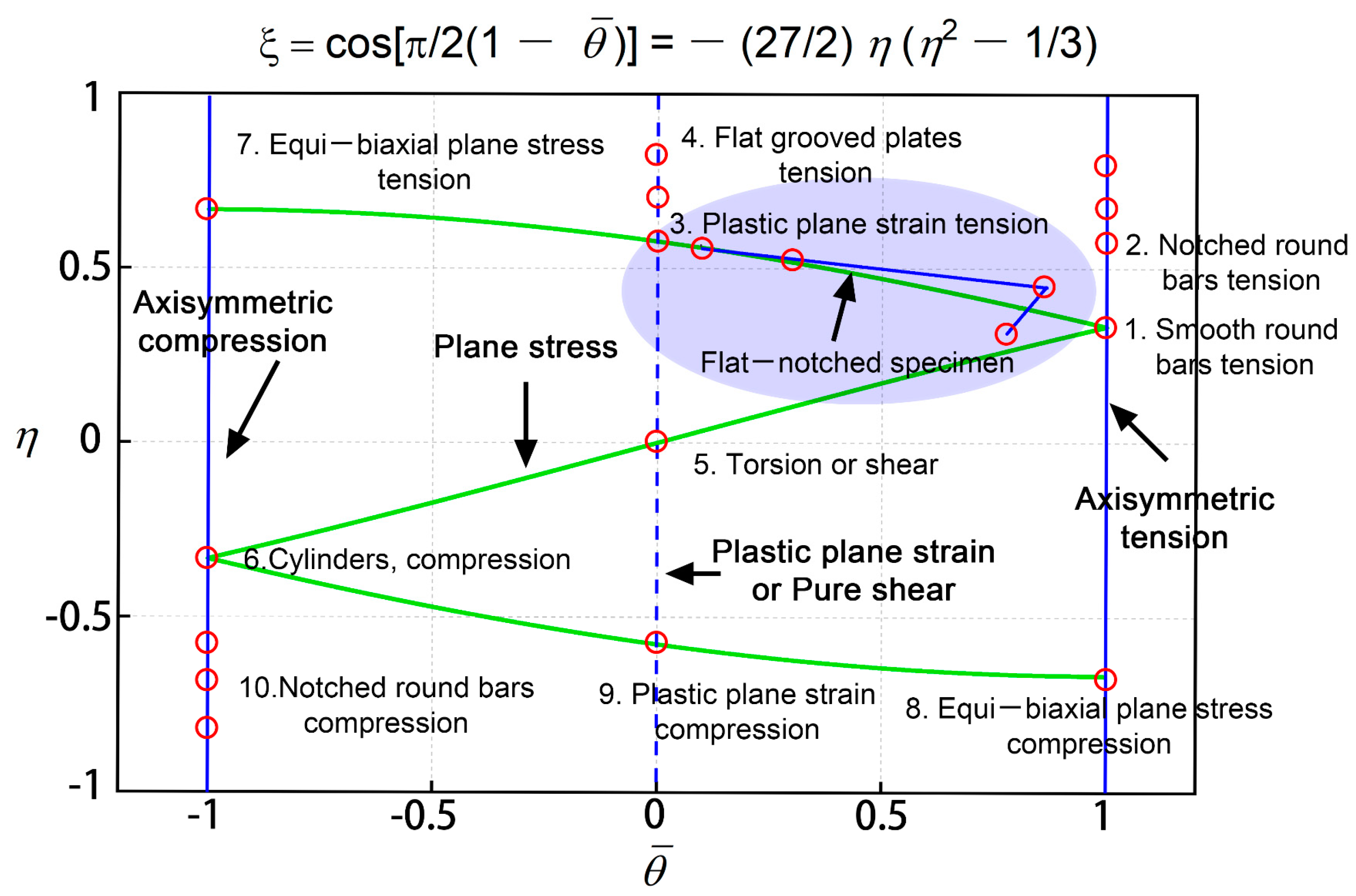
2.2. Characterization of Stress Triaxiality and Lode Angle Parameter

Stress state can be described by using stress triaxiality and Lode angle parameter. The concept of stress space is introduced to quantify the effect of stress state on material fracture strain. For isotropic materials, the mechanical behaviour is independent of the spatial direction, so three characteristic values of stress tensor, namely principal stresses ( σ 1 , σ 2 , σ 3 ), can be considered in three-dimensional principal stress space. Meanwhile, the orthogonal principal stress space can be equivalently redefined in the Lode coordinates, which is a cylindrical coordinate system, where the hydrostatic stress is the symmetry axis. The Lode coordinates can be constructed from the scaled version of three stress invariants (p, q, r), which are defined as:
p = σ m = 1 3 t r ( σ ) = 1 3 ( σ 1 + σ 2 + σ 3 )
q = σ ¯ = 3 2 S : S = 1 2 [ ( σ 1 σ 2 ) 2 + ( σ 2 σ 3 ) 2 + ( σ 3 σ 1 ) 2 ] = 3 J 2
r = [ 27 2 det ( S ) ] 1 / 3 = [ 27 2 ( σ 1 σ m ) ( σ 2 σ m ) ( σ 3 σ m ) ] 1 / 3 = [ 27 2 J 3 ] 1 / 3
where S is the deviatoric stress tensor, S = σ p I , I is the identity tensor, σ is the stress tensor, σ m and σ ¯ are the hydrostatic stress and Von Mises equivalent stress, whereas J 2 and J 3 are the second and third deviatoric stress invariants, the parameter p is positive in compression, but σ m is positive in tension.
Stress triaxiality is an important parameter to evaluate plastic restraint and considered in the plastic damage model, which is defined as the ratio of hydrostatic stress to Von Mises equivalent stress in Equation (4):
η = σ m σ ¯
Lots of experimental observations and numerical studies showed that the effect of stress state on fracture behaviour could not be fully reflected by stress triaxiality alone in establishing the damage constitutive equation of ductile materials [25,26,27]. Therefore, the stress triaxiality is not sufficient to completely characterize the stress state, and the Lode angle parameter relating to the deviating stress state should be jointly used. The Lode angle θ is defined through the normalized third deviatoric stress ξ in Equation (5):
ξ = ( r q ) 3 = cos ( 3 θ ) = 3 3 2 J 3 J 2 3 / 2 = 27 2 J 3 q 3
The Lode angle θ can be normalized by the parameter θ ¯ , which is called the Lode angle parameter:
θ ¯ = 1 6 θ π = 1 2 π arccos ξ

3. Results and Discussion

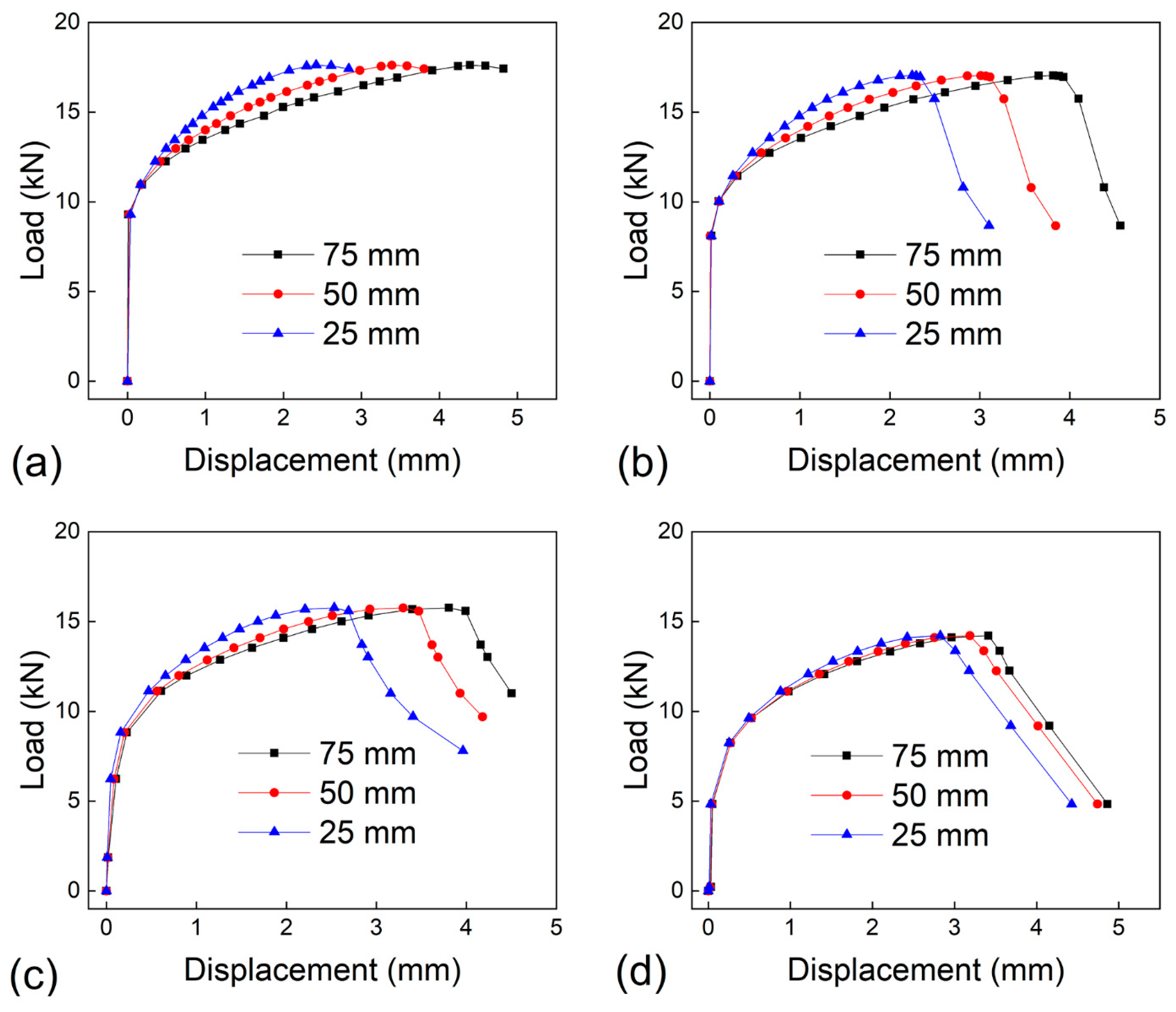
3.1. Effect of Notch Angle on Load-Displacement Curve

In order to analyse the influence of the extensometer gauge length on the load-displacement curve, DIC method is used as a virtual extensometer to characterize the load-displacement curve, and three gauge lengths of 75 mm, 50 mm and 25 mm are used. Figure 3 shows the load-displacement curves at different gauge lengths. The load-displacement curves of three gauge lengths show that the inclined notch angle has a significant influence on the strength and ductility of the notched specimen, and the maximum force gradually decreases with the increase of inclined notch angle. It is interesting that, the affecting degrees of notch angle on the load-displacement curve are different for different gauge lengths, and the affecting degree at the shortest gauge length of 25 mm in Figure 3c is greater than that at the longer gauge length of 75 mm in Figure 3a. Since the gauge length involves not only the notch, but also the parallel length, when the traditional extensometer method is used to obtain the load-displacement curves of the notched specimen, the parallel length will affect the notch angle sensitivity of load-displacement curve.
In order to give more clear comparison on the influence of gauge length, the load-displacement curves of three gauge lengths (75 mm, 50 mm, 25 mm) are compared in one figure as shown in Figure 4. Since the strain distribution is not uniformed at the specimen section, the gauge length affects the load-displacement curve especially at the plastic and fracture stages, and with the gauge length increasing, the displacement increases. Moreover, the influence degrees of gauge length are different at different notch angles, which is caused by the difference of the stress concentration degree. Therefore, the gauge length will affect the load-displacement curve, and DIC can better meet the requirements of the strain characterization for the inclined notch specimen then the extensometer with a fixed gauge length. For the uniformity in the subsequent analysis the displacement corresponding to the gauge length of 75 mm is used.

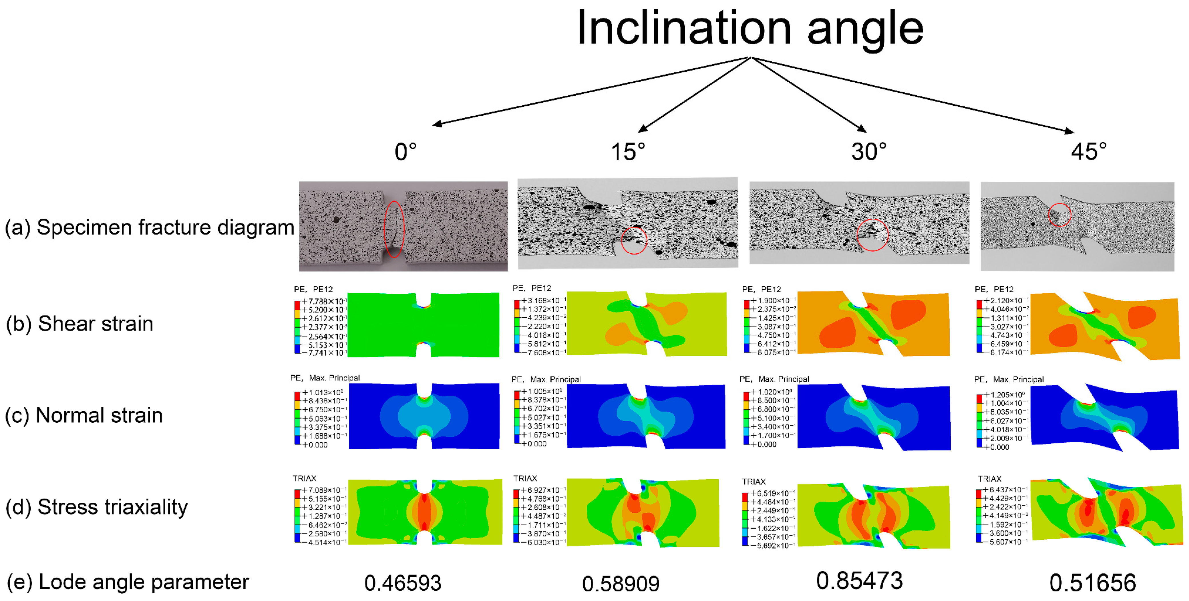
3.2. Effect of Notch Angle on Strain Field

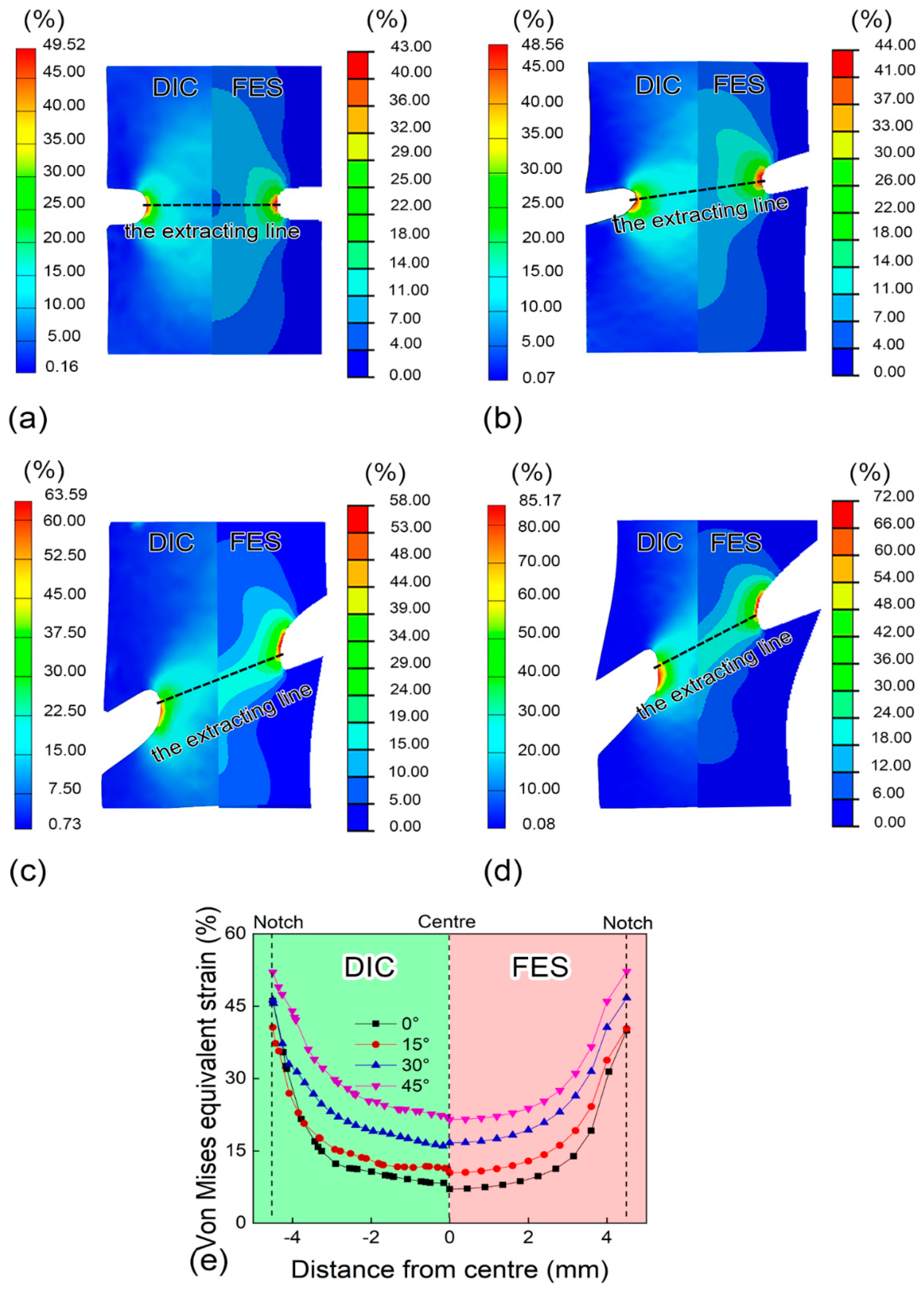
3.2.1. Comparison of Strain Fields by DIC and Finite Element Simulation

The extensometer with a standard gauge length is commonly used to acquire the load-displacement curve during the uniaxial tensile test. Previous studies on the tensile behaviour of notch specimen were mainly measured by the extensometer [4,22,28]. Since the extensometer has the limitation to characterize the local strain of inclined notched specimen, this work combines the advantages of DIC full field strain measurement method and finite element simulation to study the strain field and stress state of notched specimen. Figure 5 compares the Von Mises equivalent strain distributions obtained by DIC and finite element simulation when the relative displacement is 3 mm with the gauge length of 75 mm, from both qualitative and quantitative views. From Figure 5a–d, with the increase of inclined notch angle, the position of strain concentration shifts from notch root to the tensile direction and the plastic strain area expands. From a quantitative view, Figure 5e compares the Von Mises equivalent strain distributions of DIC and FES, and the extracting line is shown in Figure 5a–d. From both strain contour plot and quantitative strain distribution, the strain value by finite element simulation is in a good agreement with that of DIC method, which indicates that the finite element simulation can well reproduce the deformation process of the notched specimen.

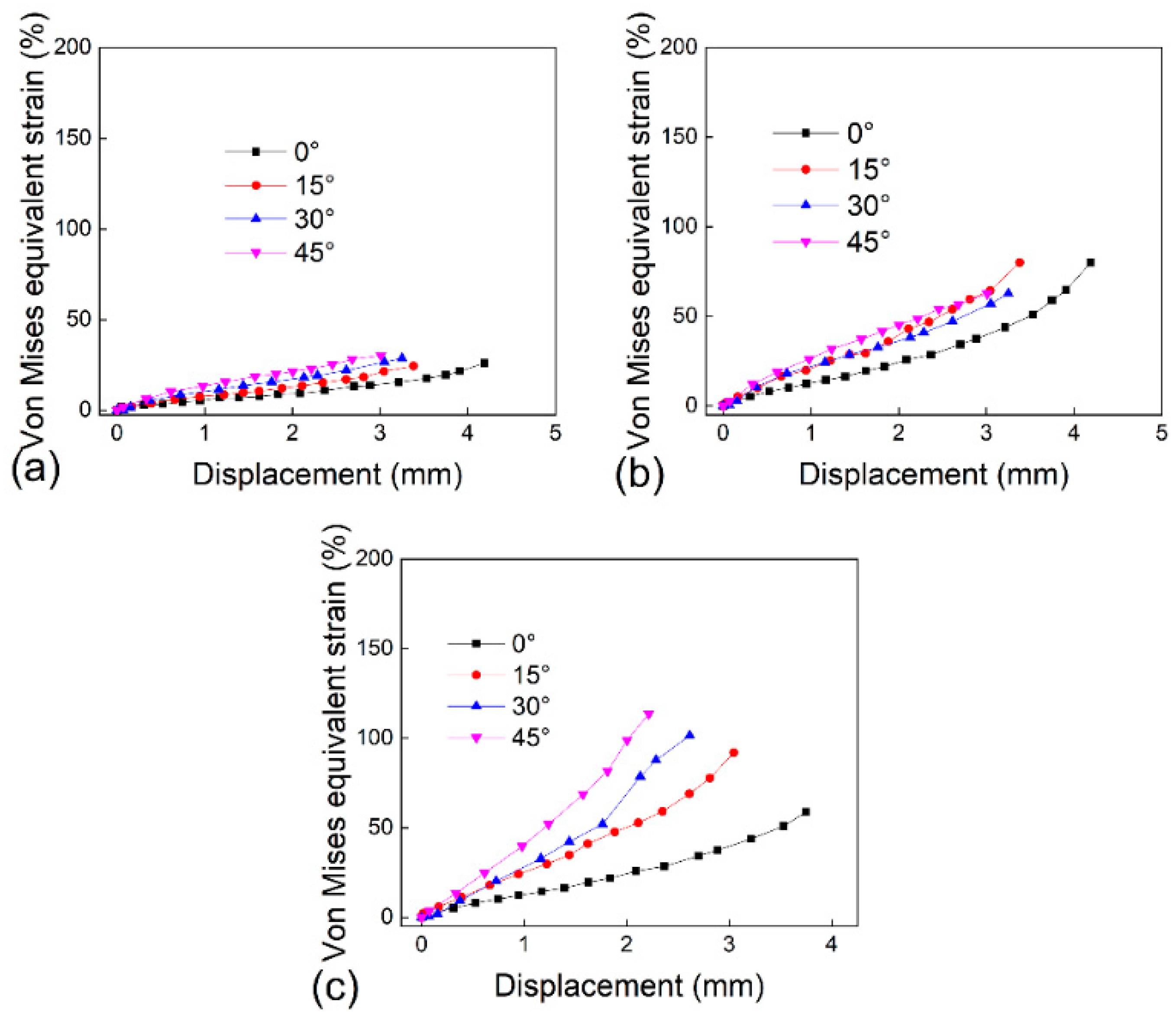
3.2.2. Strain Distribution and Evolution by DIC

From Figure 5e, it can be observed that: (1) the Von Mises equivalent strain distribution presents a “U” shape, and the valley floor is at the centre and the value rapidly increases at the notch root, which is caused by the notch strain concentration; (2) with the increase of notch angle, the distribution law is unchanging, but the value of Von Mises equivalent strain increases gradually. Since the change of notch angle leads to the change of stress state, the Von Mises equivalent strain distribution shows the inclined notch angle dependent, but at different positions, the inclined notch angle dependence of equivalent strain is different.
In order to comprehensively study the influence of the inclined notch angle on the strain evolution, Von Mises equivalent strain-displacement curves for specimens with different inclined notch angles are obtained by DIC method as shown in Figure 6, and three locations are considered, containing the centre point of the extraction path, notch root and initial failure point. As shown in Figure 6a, since the strain at the centre point is small and almost overlapped, it cannot characterize the effect of inclined notch on the strain concentration. Because the notch angle affects the strain concentration position as shown in Figure 5, the notch root point Figure 6b also can not characterize the influence of the notch angle on the strain evolution. As shown in Figure 6c, the inclined notch angle dependence of the strain evolution is very clear at the initial failure point. The larger the inclined notch angle is, the larger the Von Mises equivalent strain value is, and the faster the strain growth rate is. Comparing the results at different locations, the notch angle dependence of strain evolution at the centre point is weak in Figure 6a, at the notch root is middle in Figure 6b, and at initial failure point is significant in Figure 6c. Therefore, it is reasonable to use the initial failure point to analyse the influence of notch angle on strain evolution.

3.3. Effect of Notch Angle on Stress Triaxiality and Lode Angle Parameter

3.3.1. Distribution and Evolution of Stress Triaxiality

The exciting theoretical solutions and empirical equations of stress triaxiality and Lode angle parameter are only suitable for axisymmetric round bar specimens [7,23], and there is no theoretical equation for non-axisymmetric flat plate specimen. The stress triaxiality and Lode angle parameter of the inclined notched specimen are calculated based on Equations (4) and (6), and the principal stress (σ1, σ2, σ3) and stress deviation tensor are obtained by finite element simulation.
Figure 7b quantitatively shows the stress triaxiality distribution along the net section path of the notch at the relative displacement of 4 mm, and the extraction path is shown in Figure 7a. Figure 7c–e show the stress triaxiality evolution curves with displacement at the centre point, the notch root and the initial failure point. It can be seen from Figure 7b that, the stress triaxiality distribution also presents a “U” shape curve, and the stress triaxiality is stable within the range of ±2 mm from the centre point, but it increases near the notch root, which is due to the stress concentration and the boundary restraint effect. Moreover, the stress triaxiality decreases with the increase of the inclined notch angle. At the centre point in Figure 7c, the dependence of the stress triaxiality on the inclined notch angle is significant, but weak at the notch root in Figure 7d and the failure point in Figure 7e. Because the large plastic deformation and plastic damage first occur at the initial failure point, the geometric dimensions of inclined notched specimens at the failure position greatly change during the large deformation process, so it is difficult to distinguish the difference of stress triaxiality at the initial failure point.
From the comparison of the relationships between stress triaxiality and notch angle at different locations in Figure 7, the correlation between the stress triaxiality and notch angle is non-existent at the failure point, and is fuzzy at notch root, but is clear at the centre point. Therefore, only the centre point is suitable to characterize the relationship between the stress triaxiality and notch angle.

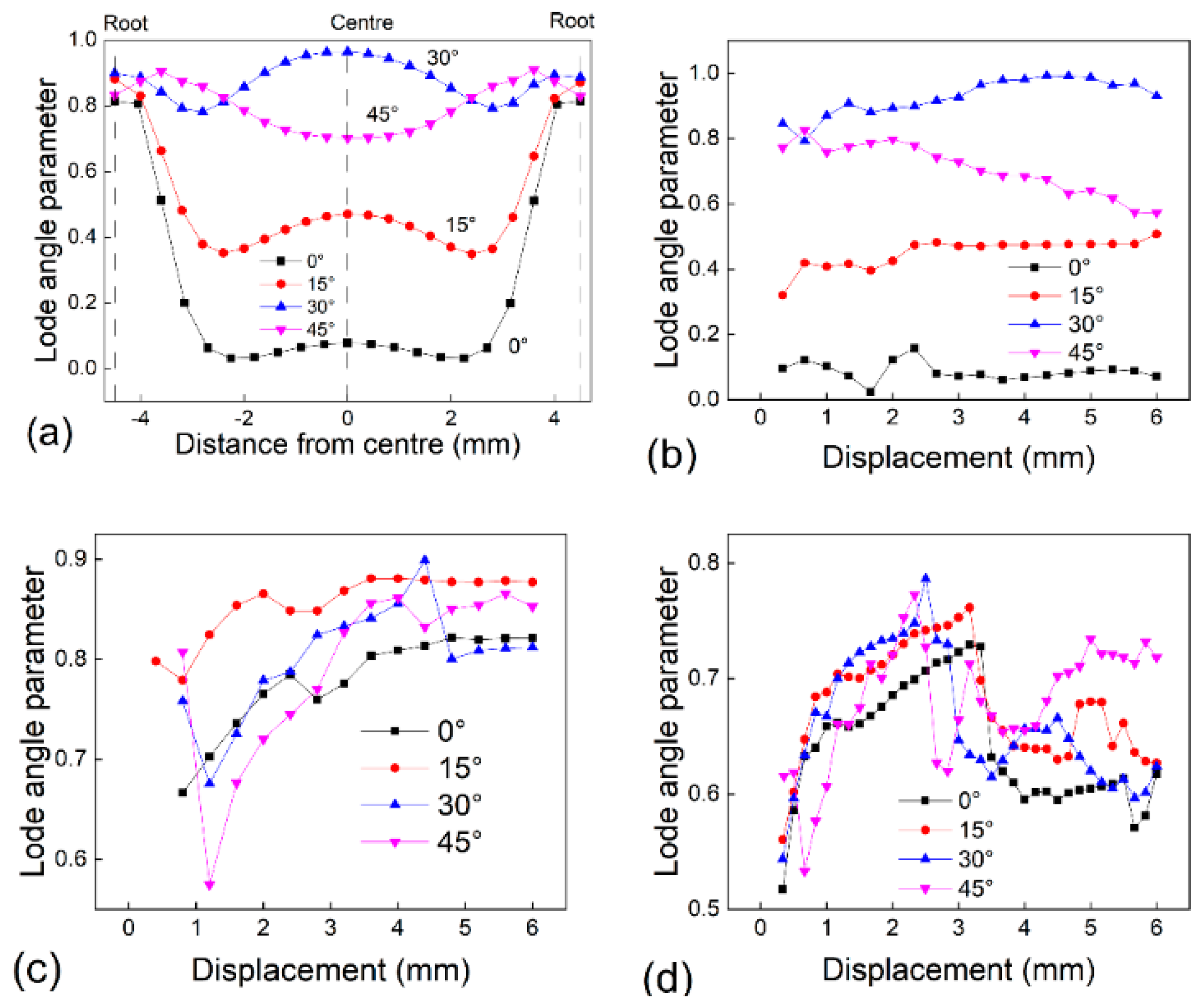
3.3.2. Distribution and Evolution of Lode Angle Parameter

Besides the stress triaxiality, Lode angle parameter is important to understand the stress state of the specimen with inclined notch. Figure 8a shows the Lode angle parameter distributions along the net section path at different inclined notch angles at the relative displacement of 4 mm, while the path is the same as that in Figure 7a. It can be seen that the Lode angle parameter distribution presents a “W” shape curve. At the notch root, the Lode angle parameters for different inclined notch angles are overlapped with the value ranging from 0.8–0.9. However, at the centre point, their differences are significant, and with the increase of the notch angle (0–30°), the Lode angle increases gradually, and when the notch angle is 30°, the Lode angle parameter is at the peak value and close to 1. As the notch angle continues to increase to 45°, the Lode angle parameter begins to decrease. Figure 8b–d shows the Lode angle parameter evolution curves with displacement at the centre point, the notch root and the initial failure point. At the centre point in Figure 8b, when the notch angle is in the range of 0° to 30°, the Lode angle parameter is stable with the displacement, and the Lode angle parameter increases with the increase in the inclined notch angle. From the results at notch root and failure point in Figure 8c,d, the evolution curves are overlapped and crossed at different inclined notch angles. The reason is that, at the failure point and notch root, the materials are severely plastic deformed, and the geometric dimensions are continuously changing.
From the comparison of the correlations between Lode angle parameter and notch angle at different locations in Figure 8, the centre point is suitable to characterize the dependence of Lode angle parameter on the inclined notch angle.

3.3.3. Characterization of Stress State

The stress state is determined by both stress triaxiality and Lode angle parameter. Wierzbicki and Xue [29] found that stress triaxiality and Lode angle parameter could be correlated by normalized third deviatoric stress ξ. Special attention is given to the plane stress state, and Equation (7) gives the relationship of stress triaxiality and Lode angle parameter for the plane stress state. The “Z” type curve of Equation (7) is given in Figure 9 [24].
ξ = cos [ π 2 ( 1 θ ¯ ) ] = 27 2 η ( η 2 1 3 )
The stress states of ten classical specimens are marked in Figure 9. Because the previous research of notched specimen did not cover the stress state of the flat metal specimen with inclined notch, the stress triaxiality and Lode angle parameter of the 0–45° inclined notched specimen studied in this paper at the same small displacement of 0.07 mm are added in the Wierzbicki stress state diagram, with the ellipse blue area in Figure 9. As shown in Figure 7c and Figure 8b, the stress triaxiality and Lode angle parameter are strongly dependent on the inclined notch angle at the centre point of the specimen. Therefore, the centre point is used to characterize the stress state of flat notched specimen in Figure 9, which is also used in the studies of the stress state of notched round bar specimens [7,30] and notched flat specimens [21,22,23]. Von Mises stress is an equivalent stress based on shear strain energy. According to the definition of stress triaxiality, the decrease of stress triaxiality represents the increase of shear load ratio. Therefore, with the increase of the notch angle, the shear load ratio increases.
It needs to be mentioned that, since this paper focuses on the effect of inclined notch on the stress state and the same notch radius is used, the variation range of stress triaxiality is limited, while that of Lode angle parameter is large, as shown in Figure 9. In further studies, more combinations of notch angles and radii are needed to construct a comprehensive stress state diagram for notched flat specimen.

3.4. Effect of Stress State on Failure Mode

In order to analyse the effect of notch angle on failure mode, Figure 10 shows the specimen fracture diagram, shear strain contour plot, normal strain contour plot, stress triaxiality contour plot and Lode angle parameter at the initial failure displacement. It can be seen from the specimen fracture diagram in Figure 10a the failure position of the specimen with the vertical notch is at the notch root, and with the increase of the inclined notch angle, the fracture position shifts from the notch root to the tensile direction. Moreover, for the specimen with the vertical notch, the thickness necking covers the entire net section of the notched specimen, but with the increase of the inclined notch angle, the thickness necking only covers the small notch root area. Therefore, the failure mode of the specimen with the vertical notch is pure ductile fracture, but with the inclined notch angle increasing, the failure mode changes from pure ductile fracture to mixed ductile and shear fracture. Comparing the shear strain in Figure 10b with the normal strain in Figure 10c, with the increase of the notch angle, the shear strain changes greatly and the shearing area is expanding, but the normal strain distribution does not change obviously, which indicates that with the increase of the inclined notch angle, the notched specimen changes from the normal strain controlled to the shear strain controlled, which leads to the change of the failure mode. From the stress triaxiality contour plot in Figure 10d, with the increase of the inclined notch angle, the maximum point of the stress triaxiality shifts from the notch root to the tensile direction, which is similar with the failure point in Figure 10a. Furthermore, the Lode angle parameter at the centre point non-monotonically changes with the increase of the inclined notch angle, as listed in Figure 10e. Therefore, the stress triaxiality and Lode angle parameter work together to affect the failure mode of the specimen with inclined notch.

4. Conclusions

In this paper, DIC and finite element simulation are used to study the stress state parameters of flat metal specimen with inclined notch, and the relationships between the stress state parameters and failure mode are analysed. The main conclusions are as following:
(1) DIC method has the advantage in presenting the non-uniform deformation, which can be utilized to characterize the local strain field for inclined notched specimen. Based on DIC results, it is found that with the increase of inclined notch angle, the failure position of notched specimen shifts from notch root to the tensile direction.
(2) Based on DIC method and finite element simulation, the distributions of strain, stress triaxiality and Lode angle parameter and their evolutions with displacement are revealed. Comparing with the centre point and notch root, the failure point can better characterize the influence of the inclined notch angle on the strain evolution. On the contrary, only the centre point can characterize the influence of the inclined notch angle on the stress state parameter evolution. Then, the stress state parameters at the centre point of the flat metal specimen with inclined notch are added on the Wierzbicki stress state diagram.

Author Contributions

Conceptualization, J.P. and P.Z.; methodology, Y.W.; software, P.Z.; validation, J.P. and Q.D.; formal analysis, Y.W.; investigation, J.P. and P.Z.; resources, J.P.; writing—original draft preparation, J.P. and P.Z.; writing—review and editing, J.P., D.K. and M.M.; visualization, P.Z.; supervision, J.P.; project administration, J.P.; funding acquisition, J.P. All authors have read and agreed to the published version of the manuscript.

Funding

This research was funded by the National Natural Science Foundation of China, Grant Number 52075050, Natural Science Foundation of Jiangsu Province, Grant Number BK20201448, Postgraduate Research and Practice Innovation Program of Jiangsu Province, Grant Number, KYCX20_2544. The authors want to thank four anonymous reviewers for their encouragement and valuable comments on the revision of this paper.

Institutional Review Board Statement

Not applicable.

Informed Consent Statement

Not applicable.

Data Availability Statement

Some data used during the study are available from the corresponding author by reasonable request.

Conflicts of Interest

The authors declare no conflict of interest.

References

  1. Luo, Y.; Jiang, W.C.; Zhang, W.Y.; Zhang, Y.C.; Woo, W.; Tu, S.T. Notch effect on creep damage for Hastelloy C276-BNi2 brazing joint. Mater. Des. 2015, 84, 212–222. [Google Scholar] [CrossRef]
  2. Zhang, Y.C.; Chen, C.; Jiang, W.C.; Tu, S.T.; Zhang, X.C. Evaluation of the creep crack growth behavior in 9Cr–1Mo steel under different stress conditions. Int. J. Press. Vessel. Pip. 2020, 88, 104174. [Google Scholar] [CrossRef]
  3. Rodriguez-Millan, M.; Garcia-Gonzalez, D.; Rusinek, A.; Arias, A. Influence of Stress State on the Mechanical Impact and Deformation Behaviors of Aluminum Alloys. Metals 2018, 8, 520. [Google Scholar] [CrossRef] [Green Version]
  4. Bao, Y.B.; Wierzbicki, T. On fracture locus in the equivalent strain and stress triaxiality space. Int. J. Mech. Sci. 2004, 46, 81–98. [Google Scholar] [CrossRef]
  5. Skripnyak, V.V.; Skripnyak, E.G.; Skripnyak, V.A. Fracture of Titanium Alloys at High Strain Rates and under Stress Triaxiality. Metals 2020, 10, 305. [Google Scholar] [CrossRef]
  6. Peng, J.; Wang, Y.; Dai, Q.; Liu, L.; Liu, X.D.; Zhang, Z.H. Effect of stress triaxiality on plastic damage evolution and failure mode for 316L notched specimen. Metals 2019, 9, 1067. [Google Scholar] [CrossRef] [Green Version]
  7. Huang, J.; Guo, Y.Z.; Qin, D.Y.; Zhou, Z.X.; Li, D.D.; Li, Y.L. Influence of stress triaxiality on the failure behavior of Ti-6Al-4V alloy under a broad range of strain rates. Theor. Appl. Fract. Mech. 2018, 97, 48–61. [Google Scholar] [CrossRef]
  8. Luo, Y.; Jiang, W.C.; Zhang, Y.C.; Zhou, F.; Tu, S.T. A new damage evolution model to estimate the creep fracture behavior of brazed joint under multiaxial stress. Int. J. Mech. Sci. 2018, 149, 178–189. [Google Scholar] [CrossRef]
  9. Kiran, R.; Khandelwal, K. A triaxiality and Lode parameter dependent ductile fracture criterion. Eng. Fract. Mech. 2014, 128, 121–138. [Google Scholar] [CrossRef]
  10. Liu, Z.G.; Wong, W.H.; Guo, T.F. Void behaviors from low to high triaxialities: Transition from void collapse to void coalescence. Int. J. Plast. 2016, 84, 183–202. [Google Scholar] [CrossRef]
  11. Lin, Y.C.; Zhu, X.H.; Dong, W.Y.; Yang, H.; Xiao, Y.W.; Kotkunde, N. Effects of deformation parameters and stress triaxiality on the fracture behaviors and microstructural evolution of an Al-Zn-Mg-Cu alloy. J. Alloys Compd. 2020, 832, 154988. [Google Scholar] [CrossRef]
  12. Kondori, B.; Benzerga, A. Effect of stress triaxiality on the flow and fracture of Mg alloy AZ31. Metall. Mater. Trans. A 2014, 45, 3292–3307. [Google Scholar] [CrossRef]
  13. Li, Z.; Zhou, Y.; Wang, S.X.; Palumbo, D. Influence of strain and stress triaxiality on the fracture behavior of GB 35CrMo steel during hot tensile testile. Adv. Mater. Sci. Eng. 2018, 2018, 5124524. [Google Scholar] [CrossRef] [Green Version]
  14. Xue, L. Damage accumulation and fracture initiation in uncracked ductile solids subject to triaxial loading. Int. J. Solids Struct. 2007, 44, 5163–5181. [Google Scholar] [CrossRef] [Green Version]
  15. Liu, L.X.; Zheng, Q.L.; Zhu, J.; Li, Z.Q. Effects of Stress Triaxiality and Lode Parameter on Ductile Fracture in Aluminum Alloy. Rare Met. Mater. Eng. 2019, 48, 433–439. [Google Scholar]
  16. Srivastava, A.; Needleman, A. Void growth versus void collapse in a creeping single crystal. J. Mech. Phys. Solids 2013, 61, 1169–1184. [Google Scholar] [CrossRef]
  17. Zhu, Y.Z.; Engelhardt, M.D.; Kiran, R. Combined effects of triaxiality, Lode parameter and shear stress on void growth and coalescence. Eng. Fract. Mech. 2018, 199, 410–437. [Google Scholar] [CrossRef]
  18. Ma, Y.S.; Sun, D.Z.; Andrieux, F.; Zhang, K.S. Influences of initial porosity, stress triaxiality and Lode parameter on plastic deformation and ductile fracture. Acta Mech. Solida Sin. 2017, 30, 493–506. [Google Scholar] [CrossRef]
  19. Maysam, B.; Dirk, M. Micro-tension and micro-shear experiments to characterize stress-state dependent ductile fracture. Acta Mater. 2017, 131, 65–76. [Google Scholar]
  20. Anderson, D.; Winkler, S.; Bardelcik, A.; Worswick, M.J. Influence of stress triaxiality and strain rate on the failure behavior of a dual-phase DP780 steel. Mater. Des. 2014, 60, 198–207. [Google Scholar] [CrossRef]
  21. Malcher, L.; Morales, L.; Rodrigues, V.; Silva, V.; Araújo, L.; Ferreira, G.; Neves, R. Experimental program and numerical assessment for determination of stress triaxiality and J3 effects on AA6101-T4. Theor. Appl. Fract. Mech. 2020, 106, 102476. [Google Scholar] [CrossRef]
  22. Zhang, X.W.; Wen, J.F.; Zhang, X.C.; Wang, X.G.; Tu, S.T. Effects of the stress state on plastic deformation and ductile failure: Experiment and numerical simulation using a newly designed tension-shear specimen. Fatigue Fract. Eng. Mater. Struct. 2019, 42, 2079–2092. [Google Scholar] [CrossRef]
  23. Li, W.C.; Liao, F.F.; Zhou, T.H.; Askes, H. Ductile fracture of Q460 steel: Effects of stress triaxiality and Lode angle. J. Constr. Steel Res. 2016, 123, 1–17. [Google Scholar] [CrossRef]
  24. Bai, Y.L.; Wierzbicki, T. A new model of metal plasticity and fracture with pressure and Lode dependence. Int. J. Plast. 2007, 24, 1071–1096. [Google Scholar] [CrossRef]
  25. Wierzbicki, T.; Bao, Y.B.; Lee, Y.W.; Bai, Y.L. Calibration and evaluation of seven fracture models. Int. J. Mech. Sci. 2005, 47, 719–743. [Google Scholar] [CrossRef]
  26. Barsoum, I.; Faleskog, J. Rupture mechanisms in combined tension and shear-experiments. Int. J. Solids Struct. 2007, 44, 1768–1786. [Google Scholar] [CrossRef] [Green Version]
  27. Bai, Y.L.; Teng, X.Q.; Wierzbicki, T. On the application of stress triaxiality formula for plane strain fracture testing. J. Eng. Mater. Technol. 2009, 131, 021002. [Google Scholar] [CrossRef]
  28. Yu, S.Y.; Cai, L.X.; Yao, D.; Bao, C. Critical ductile fracture criterion based on first principal stress and stress triaxiality. Theor. Appl. Fract. Mech. 2020, 109, 102696. [Google Scholar] [CrossRef]
  29. Wierzbicki, T.; Xue, L. On the Effect of the Third Invariant of the Stress Deviator on Ductile Fracture; Technical Report; Impact and Crashworthiness Laboratory, Massachusetts Institute of Technology: Cambridge, MA, USA, 2005. [Google Scholar]
  30. Huang, X.W.; Ge, J.Z.; Zhao, J.; Zhao, W. A continuous damage model of Q690D steel considering the influence of Lode parameter and its application. Constr. Build. Mater. 2020, 262, 120067. [Google Scholar] [CrossRef]
Figure 1. True stress-true strain curve of 316L.
Metals 11 01627 g001
Figure 2. Notched specimen: (a) geometric dimension; (b) finite element mesh.
Metals 11 01627 g002
Figure 3. The load-displacement curve of specimen with inclined notch at different gauge lengths: (a) the gauge length of 75 mm; (b) the gauge length of 50 mm; (c) the gauge length of 25 mm.
Metals 11 01627 g003
Figure 4. The load-displacement curves at different gauge lengths for inclined notch specimen: (a) 0°; (b) 15°; (c) 30°; (d) 45°.
Metals 11 01627 g004
Figure 5. Comparison of Von Mises equivalent strain contour plot by DIC method and finite element simulation: (a) vertical angle; (b) 15° inclined notch; (c) 30° inclined notch; (d) 45° inclined notch; (e) Von Mises equivalent strain distribution. DIC: digital image correlation, FES: finite element simulation.
Metals 11 01627 g005
Figure 6. Von Mises equivalent strain-displacement curve: (a) at centre point; (b) at notch root; (c) at initial failure point.
Metals 11 01627 g006
Figure 7. Distribution and evolution of stress triaxiality: (a) extraction path; (b) stress triaxiality distribution; (c) at centre point; (d) at notch root; (e) at initial failure point.
Metals 11 01627 g007
Figure 8. Distribution and evolution of Lode angle parameter: (a) Lode angle parameter distribution; (b) at centre point; (c) at notch root; (d) at initial failure point.
Metals 11 01627 g008
Figure 9. The stress state of the specimen with inclined notch in the Wierzbicki stress state diagram.
Metals 11 01627 g009
Figure 10. Correlations of specimen fracture diagram, shear strain contour plot, normal strain contour plot, stress triaxiality contour plot and Lode angle parameter: (a) specimen fracture diagram; (b) shear strain contour plot; (c) normal strain contour plot; (d) stress triaxiality contour plot; (e) Lode angle parameter.
Metals 11 01627 g010
Publisher’s Note: MDPI stays neutral with regard to jurisdictional claims in published maps and institutional affiliations.

