Hydrogen Ironmaking: How It Works


Institut Jean Lamour, CNRS, Université de Lorraine, Labex DAMAS, 54011 Nancy, France
*
Author to whom correspondence should be addressed.
Metals 2020, 10(7), 922; https://doi.org/10.3390/met10070922
Submission received: 3 June 2020
/
Revised: 29 June 2020
/
Accepted: 30 June 2020
/
Published: 9 July 2020
(This article belongs to the Special Issue Challenges and Prospects of Steelmaking Towards the Year 2050)
Abstract
:A new route for making steel from iron ore based on the use of hydrogen to reduce iron oxides is presented, detailed and analyzed. The main advantage of this steelmaking route is the dramatic reduction (90% off) in CO2 emissions compared to those of the current standard blast-furnace route. The first process of the route is the production of hydrogen by water electrolysis using CO2-lean electricity. The challenge is to achieve massive production of H2 in acceptable economic conditions. The second process is the direct reduction of iron ore in a shaft furnace operated with hydrogen only. The third process is the melting of the carbon-free direct reduced iron in an electric arc furnace to produce steel. From mathematical modeling of the direct reduction furnace, we show that complete metallization can be achieved in a reactor smaller than the current shaft furnaces that use syngas made from natural gas. The reduction processes at the scale of the ore pellets are described and modeled using a specific structural kinetic pellet model. Finally, the differences between the reduction by hydrogen and by carbon monoxide are discussed, from the grain scale to the reactor scale. Regarding the kinetics, reduction with hydrogen is definitely faster. Several research and development and innovation projects have very recently been launched that should confirm the viability and performance of this breakthrough and environmentally friendly ironmaking process.
1. Introduction
Despite the use of the present tense in the title, using just hydrogen as a reductant for ironmaking is not yet an industrial process. However, it could become one soon according to several recent signs. Important R&D&I (research and development and innovation) programs around the world have recently been launched for this purpose. In Europe, the HYBRIT project, which aims at building a whole demonstration plant in Sweden, including an iron ore direct reduction unit fed with hydrogen by a water electrolysis plant using fossil-free electricity, is one example [1]. The H2FUTURE and GrInHy projects, though directly connected to iron or steelmaking, mostly focus on electrolyzer development [2,3]. Recently, ArcelorMittal announced the start of hydrogen-based ironmaking in its MIDREX direct reduction plant in Hamburg [4]. In parallel, increasing demand from the steel sector is expected in the energy industry: “In the iron and steel industry, where hydrogen can be used to reduce iron ore to iron, we expect the use of clean hydrogen will be demonstrated by 2030 and gain momentum by 2035” [5].
The idea of using hydrogen as a reductant is primarily related to the issue of climate change. The steel industry accounts for between 4% and 7% of global anthropogenic CO2 emissions [6]. This results from the almost exclusive use of carbon (coal or coke) for both the energy and the chemical reduction needed along the steelmaking route, the major contributor being the blast furnace, in which the solid iron ore, in the form of sinter or pellets, is transformed into liquid pig iron. Most iron ores are oxides (usually hematite Fe2O3), and the chemical reduction of an iron oxide to Fe0 by C (or by CO made from C or from CH4) produces CO2. The basic concept of hydrogen ironmaking is to substitute C (or CO) reductant with H2, replacing
or
with
thus releasing harmless H2O instead of the greenhouse gas CO2 in the chemical reduction step.
In the steelmaking route, the operations converting the ore into metallic iron are referred to as ironmaking. The majority (90%) of ironmaking is made using the blast furnace, which produces pig iron, i.e., liquid iron saturated in C. The other processes are the so-called direct reduction (DR) processes, whose product is solid iron (DRI-direct reduced iron, also named sponge iron, or HBI–hot briquetted iron). The reduction occurs as a series of gas-solid reactions with the reactant gases CO and H2. The reactor is generally a vertical shaft furnace, whose reducing gas (a CO-H2 mixture) is obtained by natural gas reforming. The corresponding industrial processes are MIDREX and HYL-ENERGIRON. Rotary earth furnaces are also employed, using coal as the carbon source.
If this substitution (C by H2) was carried out in the blast furnace, the substitution rate would remain limited. Indeed, the pulverized coal injected at the tuyeres (one-third of the carbon) could probably be largely replaced by H2, but the coke (two-thirds of the carbon) needs to remain for proper operation of the blast furnace. The expected benefit in terms of CO2 emissions is typically reported to be 20% [7]. Conversely, if a direct reduction shaft furnace was used, the possibility of substituting 100% of the carbon (monoxide) with H2 could be envisaged. This is why most of the current projects mentioned above consider using pure hydrogen in a shaft furnace for ironmaking. Presenting a way that this could be achieved for steelmaking and detailing the underlying physicochemical and thermal issues are the objectives of the present paper. Another recent paper on this topic is that of Vogl et al. [8]. Nevertheless, the scope of this paper was more focused on energy and cost and less focused on physicochemical processes than the present paper.
With different processes, reductants other than hydrogen could be used, such as electrons, thus leading to iron ore electrolysis at high or low temperatures. Interesting projects are currently ongoing, such as MOE at MIT [9] and SIDERWIN in Europe [10], but these lie outside of the scope of our paper.
2. The Hydrogen-Based Route to Steel
To the best of our knowledge, the first comprehensive study on hydrogen-based steelmaking was that undertaken by the ‘Hydrogen’ subproject of the European program ULCOS (ultra-low CO2 steelmaking, 2004–2010), in which our research group was involved. A comprehensive overview of ULCOS was recently written [11]. In the Hydrogen subproject, the tasks dealt with massive hydrogen production and the feasibility of using pure hydrogen for ironmaking.
The stoichiometric consumption of hydrogen for reducing hematite is 54 kg per ton of iron. A 1 Mt per year steel plant would require a hydrogen plant capacity of as much as 70,000 . Large-scale hydrogen production is currently achieved by steam reforming of methane. This option could be retained and even optimized for hydrogen-based ironmaking, e.g., by targeting a 97–98% purity of H2 instead of the usual 99.9+. However, since based on a fossil resource, the performance in terms of CO2 mitigation would overall remain average, unless a CO2 capture unit was added, which represents a strategy different from the one pursued. The other preferable option is to produce hydrogen by water electrolysis, provided that the electricity is fossil-free. The size of the plant could be achieved by multiplying the electrolytic cells. New, improved technologies have been identified, such as proton exchange membranes and high pressure or high temperature electrolysis. The former two are now being developed in the H2FUTURE and GrInHy projects.
Two ways to reduce iron ore by hydrogen were studied in ULCOS. The first was the reduction of fine ores in a cascade of fluidized beds, as in the FINMET process [12], but with hydrogen instead of reformed natural gas. It must be stressed that the hydrogen reduction of fine ores in a two-stage fluidized bed process, named CIRCORED, was the only direct reduction process using pure hydrogen as a reductant that had ever been commercially operated [13]. Hydrogen was produced by natural gas steam reforming. This process was decommissioned for economic rather than technical reasons. The second process investigated was the direct reduction of iron ore pellets or lumps in a vertical shaft furnace, such as a MIDREX furnace. The latter process, which is detailed in the next section, was eventually selected.
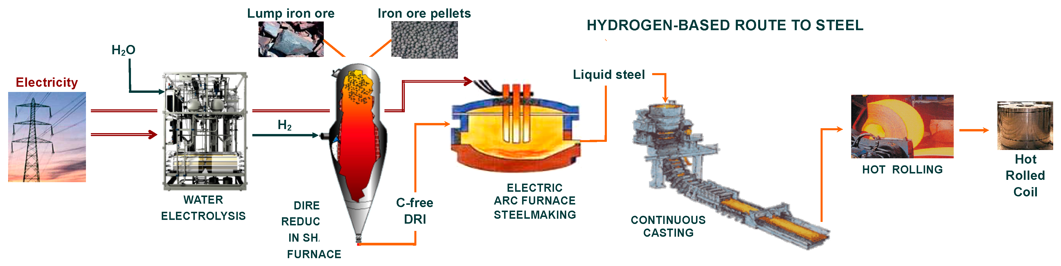
The whole route to steel proposed based on these investigations is depicted in Figure 1. Unsurprisingly, the current hydrogen-based ironmaking projects have retained the same route.
The rest of the route, the steelmaking process that employs an electric arc furnace (EAF), is the same as the usual route for making steel from recycled scrap or from DRI. The only difference lies in the carbon content of the DRI, which is 0% instead of 2–4%. Some EAF steelmakers might be worried about the use of such a DRI since the current practice is to look for DRIs with higher carbon contents. Nuber et al. cogently addressed this question and concluded that carbon-free DRI is not an issue [13]. Plain scrap charges, without carbon, are routinely treated in most EAFs, and the important point is to obtain a good foaming slag by blowing carbon fines and oxygen.
The performance of the whole route, in terms of energy consumption and CO2 emissions, is indicated in Table 1 (last line) and compared with that of the standard blast furnace-basic oxygen furnace route, as well as with that of the usual direct reduction (MIDREX process) followed by electric arc steelmaking.
Regarding the hydrogen-based route, three sources are reported, which give different figures. This discrepancy has to be related to the assumptions and to the boundaries of the system. The ULCOS [14,15] figures reflect a global life cycle approach, from cradle (extraction) to gate (1 ton of hot-rolled coil). The HYBRIT and Vogl figures are for 1 ton of liquid steel. The energy comparison shows similar energy consumption for the two direct reduction routes, which is slightly lower than that of the standard BF-BOF route, and the hydrogen-based route is at the same level as the natural-gas-based route. The CO2 comparison is more instructive. While the usual natural gas DR route, with 970 kgCO2eq/tHRC, halves the CO2 emissions of the standard BF-BOF route, the hydrogen route reaches far lower levels, 25 to 200 kgCO2eq/tHRC, i.e., an 89–99% reduction in CO2 emissions. Here, again, the differences among the sources reflect the systems considered. The upstream pellet-making process and the downstream continuous casting and hot rolling processes are included in [15], whereas HYBRIT’s figure excludes the latter and considers neutral pellet making (using biomass), as well as using biomass in the EAF [1]. In any case, the dramatic decrease in CO2 emissions is definitely the rationale for developing hydrogen ironmaking.
3. Shaft Furnace using just Hydrogen
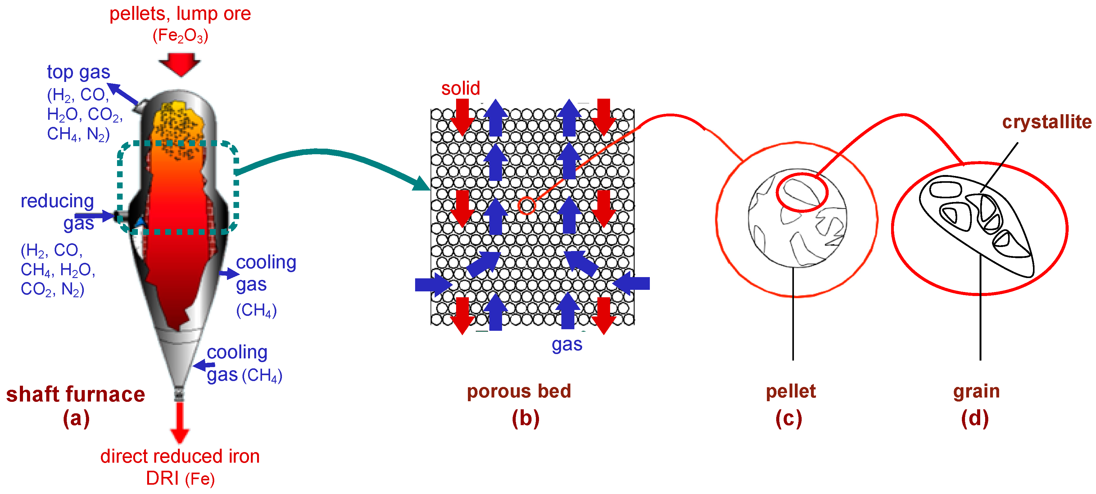
The shaft furnace is the heart of the hydrogen-ironmaking process, and the crucial question is as follows: can such a shaft furnace be operated under pure H2 and produce a well-metallized DRI, similar to the current ones—except of course for its carbon content? Some of the projects mentioned above, such as HYBRIT, plan to answer this question by building and operating a pilot/demonstration plant. This is obviously a necessary step. However, another approach can provide an interesting preliminary answer to the question: mathematical modeling. Several mathematical models of the MIDREX and HYL-ENRGIRON processes have been published, and the more detailed models [16,17,18,19] provide valuable insights into the detailed physicochemical and thermal behaviors of the reactor. Unfortunately, these models were not used to simulate the case of a shaft furnace operated with hydrogen only. Our research group developed such a model, named REDUCTOR, which, in its first version (v1), was used to study this case [20,21]. The principle of this model is illustrated in Figure 2.
The shaft furnace (Figure 2a) is fed with pellets or lump ore at the top, which descend by gravity and encounter a rising flow of hydrogen, fed laterally at mid-height of the reactor and exiting at the top. The reduction reactions take place in the upper section between the reducing gas outlet and inlet. The conversion to iron is completed at the level of the gas inlet. Below, a conical section can be used to cool the DRI, but preferably using hydrogen instead of methane. The rest of the gas circuit, not shown, is much simpler than that in the MIDREX process: the top gas, consisting of H2-H2O, is cooled to condense water, and H2 is recycled, mixed with fresh H2 from the electrolysis plant, and reheated to the desired temperature (800–900 °C).
The model simulates the reduction section in two dimensions (radius and height) and in the steady-state regime. It describes the solid and gas flows (Figure 2b), the heat transfer by convection and conduction, and the three reduction reactions
the kinetics of which are calculated from a single-pellet kinetic submodel (see Section 4). Indeed, four scales are considered (Figure 2a–d): the reactor, the pellet bed, the pellets, and the grains and crystallites composing the pellets. The local mass, energy, and momentum balances are rendered discrete and solved iteratively using the finite volume method. The equations were detailed in [20] and are not reproduced here. That paper from our group also presented preliminary results, which were updated in [21] and are shown and discussed below.
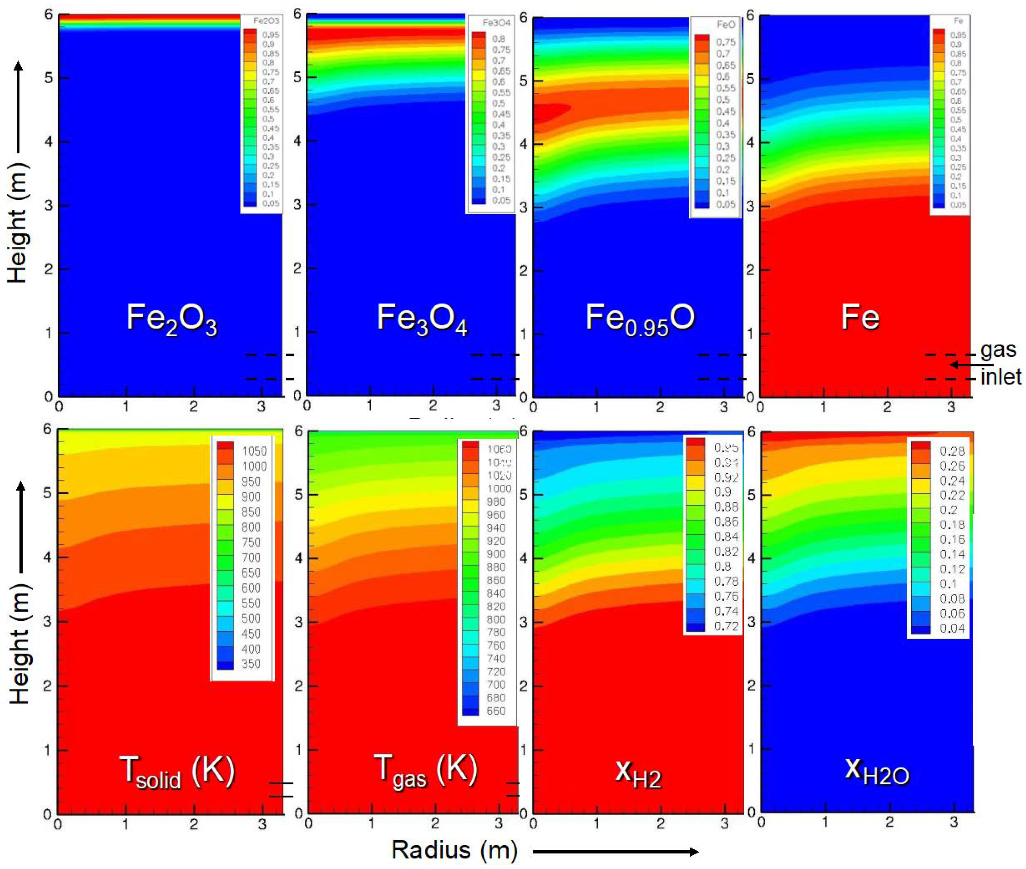
We simulated a cylindrical shaft using the geometry and inlet characteristics indicated in Table 2. The main results are presented in Figure 3.
Regarding the solid mass fractions, these results show that hematite is very rapidly converted to magnetite, followed by the magnetite-to-wustite conversion, which is completed 1.5 m down from the solid inlet. The wustite-to-iron reduction is slower and ends at z = 2.6 m, i.e., at 3.4 m from the top. The solid and gas temperatures are close to each other, being equal to the gas inlet temperature in the lower half of the shaft and between 1073 and 900 K above, due to the endothermic nature of the reactions (5,6) (see Section 5), and fall abruptly approaching the solid inlet, where the solid enters at 25 °C. The H2 and H2O molar fraction maps reflect the course of the reductions that consume H2 and produce H2O. The thermodynamic conditions produce a reducing environment that can yield 100% iron in the metallic form (Fe0). The radial profiles are mostly flat with a slight incline towards the symmetry axis. These radial gradients result from the lateral gas inlet at the wall. The principal result of this simulation is that full metallization is reached at 3.4 m, which can be compared to the 10 m reduction zone of a MIDREX shaft.
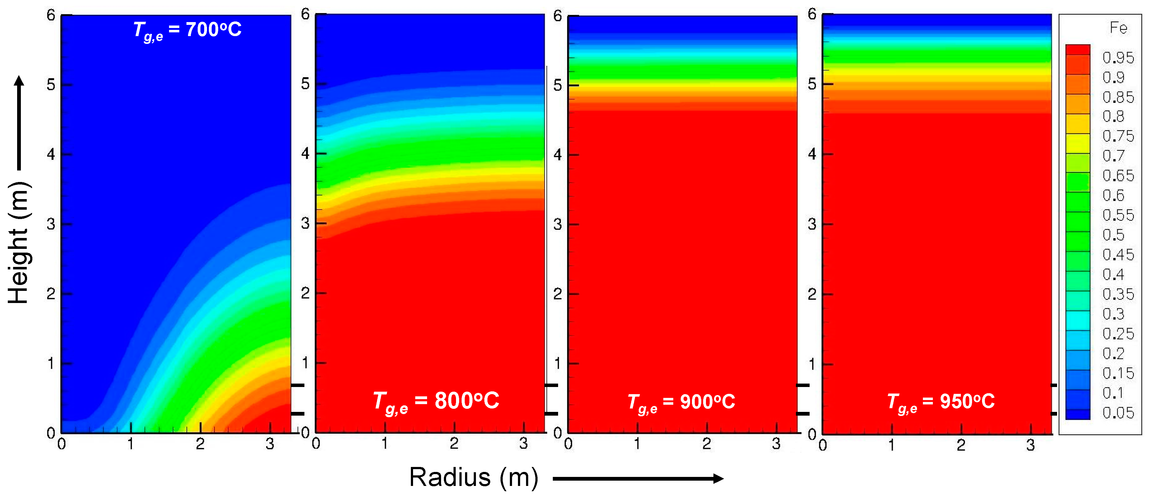
In addition to this reference simulation, the influence of some operating parameters was studied [21]. Figure 4 shows the influence of the inlet gas temperature on the iron mass fraction. At 700 °C, the shaft furnace is not heated enough, and the average iron fraction is 74% with strong radial gradients. At 900 and 950 °C, the reaction is faster than that at 800 °C, with 100% iron obtained in less than 2 m. The profile becomes flat, and the difference is small between 900 and 950 °C. This last trend is explained by the kinetics of the wustite-to-iron reaction in Section 4.
These simulations were not intended for use in designing a reactor. More design features are needed. However, the implications of the main results are clear.
4. Kinetics of Iron Ore Reduction by H2
Due to its economic importance, the reduction of iron oxides has been thoroughly studied. Thousands of papers have been published over the last century (Table 3). The reduction of iron oxides has been carried out with CO, H2, and CO-H2 mixtures. The samples, sized from mg to kg, ranged from pure synthetic oxides, either dense pieces or in powder form, to ores such as hematite and magnetite, in the form of lumps, sinter, and pellets.
All aspects of the reduction reactions were covered: mechanisms, kinetics, and influence of the reducing conditions such as temperature and gas composition. Reviewing this literature is out of the scope of the present paper; a detailed review was presented by Ranzani in 2011 [21], and a very recent review was reported by Zare Ghadi et al. [22]. Only the most important results from the literature and related to the kinetics are recalled here. The whole reduction occurs in two or three steps , with the occurrence of FeO only above 570 °C. The kinetics of the last reduction are the slowest of the three. Depending on the experimental conditions, the iron phase formed can be dense or porous, which influences the transport process (gas-phase or solid-state diffusion) through the iron layer. The reaction kinetics are said to be controlled by a chemical reaction step, a gas diffusion step, a solid diffusion step, or to be in a mixed regime according to the experimental conditions and the authors. Regarding the reactant, the reaction with H2 is generally reported to be faster than that with CO.
To obtain a kinetic model that could be integrated into the reactor model (Section 3), our research group performed a number of kinetics experiments on the reduction of iron ore pellets by hydrogen using thermogravimetry. After testing synthetic oxides and then small cubes made from ore pellets, we eventually used whole industrial pellets as samples to obtain the relevant data for modeling. The main parameters studied were the temperature, hydrogen content (H2 in He), pellet size, and pellet type (Brazilian CVRD pellets of DR and BF grades, Swedish LKAB-KPRS pellets).
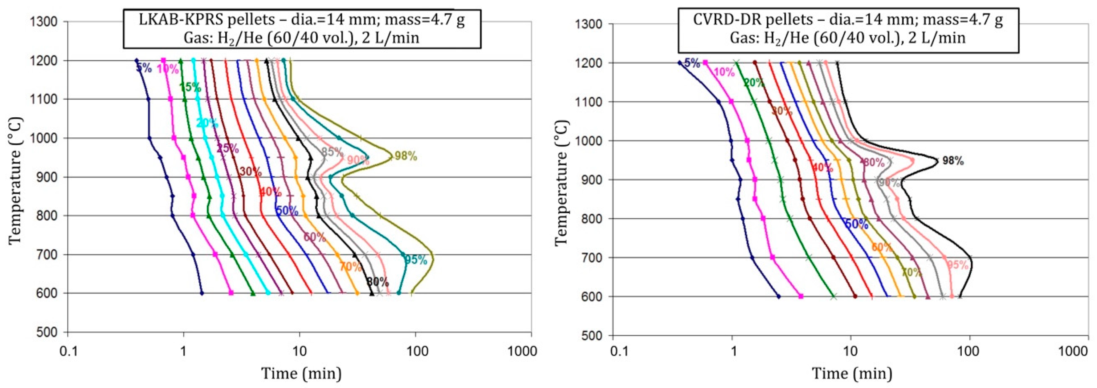
Details about the experiments and results can be found elsewhere [20,21]. The main findings, including materials only presented so far in Ranzani’s thesis, are given hereafter. The influence of temperature is particularly complex, suggesting different kinetic regimes. The conversion normally accelerates when the temperature increases but not regularly. In particular, a slowing of the kinetics is observed at the end of the reaction at certain temperatures, namely, 700 and 950 °C, as illustrated by the TTT (time-temperature-transformation) diagram of Figure 5. The slowing at 950 °C was attributed to the phase transformation at 912 °C, as the solid-state diffusion through iron is slower in the phase. Both types of pellets tested exhibit the same behavior.
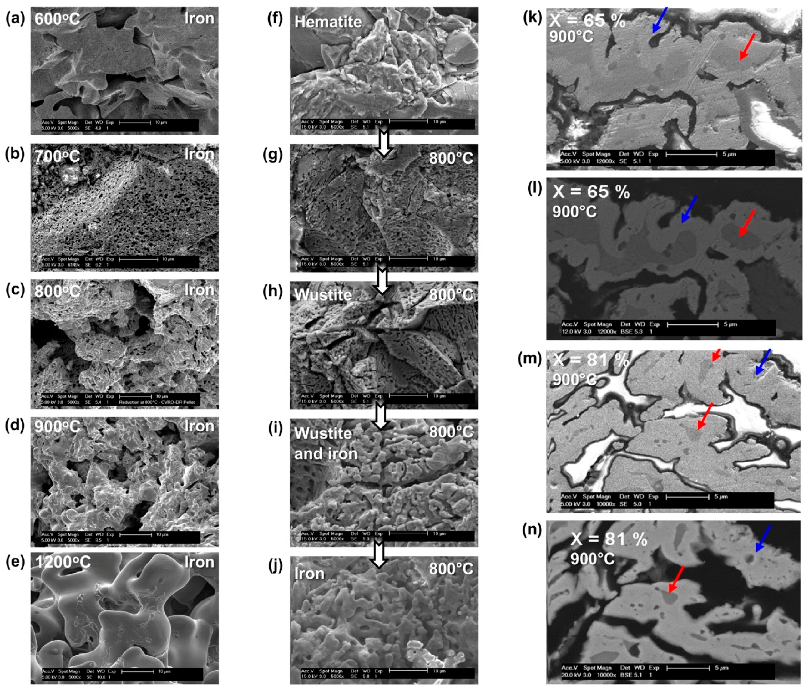
Scanning electron microscopy observations revealed changes in the pellet internal structure, as shown in Figure 6. The initial structure of a pellet is a porous agglomerate of dense hematite grains (f). It does not change much at the pellet scale after reduction, except for a slight increase in the porosity. Conversely, at the grain scale, the particles transform. The iron grains (a–e) clearly differ from the initial hematite grains, and the metamorphosis depends on the temperature; the iron grains formed at high temperature are larger and smoother. The center column (f–j) depicts the transformation over time. Some pores first appear at the surface of the grains (g–h). Then, at the stage of wustite, the grains tend to break into smaller ones, which we call crystallites (i). Eventually, the iron phase grows internally at the expense of the shrinking wustite cores of the crystallites (k–n) and, at temperatures over 900 °C, spreads over the crystallites and tends to merge them. This last behavior and micrographs similar to (k–n) were reported in [23].
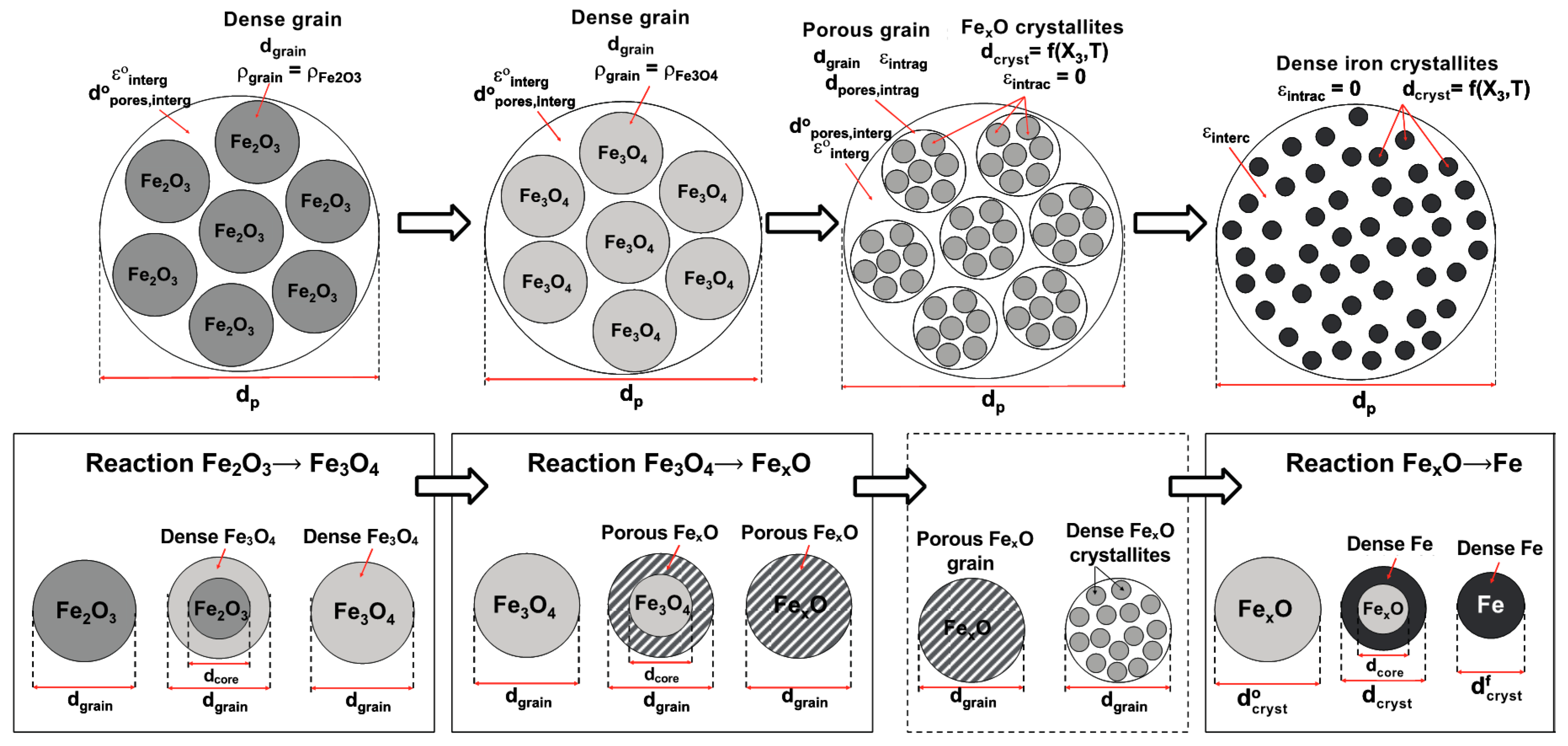
The successive reactions (4–6), the peculiar influence of the temperature, and the morphological evolution led us to build a specific ‘kinetic’ model to predict the rate of the transformations. Indeed, a simple shrinking core model, even one with three interfaces (interfaces that are not observed at the pellet scale), could not mimic these features. A grain model (pellets made up of grains) is better adapted but has to take into account the three reactions and the grain and pore evolution. It also has to remain sufficiently simple to be later included in a multiparticle reactor model. We thus developed the model illustrated in Figure 7, which physically reflects the structural evolution observed. Mathematically, it is based on an extension of Sohn’s law of additive reaction times [24], the advantage of which is its ability to simply take into account multiple possible rate-limiting processes and mixed kinetic regimes. The processes considered here are external transfer of H2 from the bulk gas to the pellet surface and the reverse for H2O, intergranular and intragranular transport of H2 and H2O by pore diffusion, and solid-state diffusion through the dense iron layer. The porosity and the pore grain diameters vary over the reaction and according to the temperature, the values of which are derived from measurements. The set of corresponding equations was given in [20].
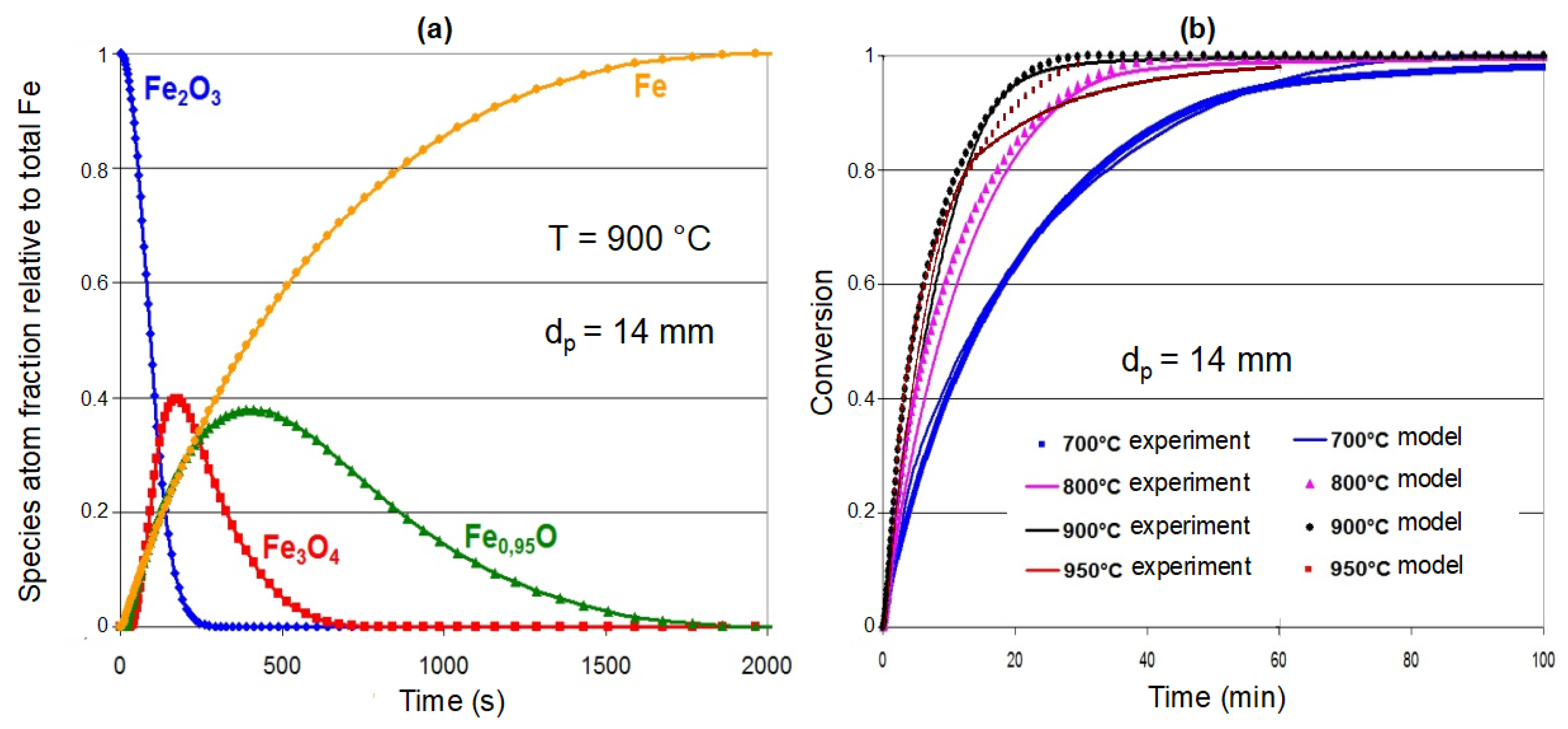
Using this single pellet kinetic model, it is possible to calculate the transformation rate as a function of the operating conditions, namely, the gas composition, flow rate and temperature. The sequence of transformation is illustrated in Figure 8a. The reduction of hematite to magnetite is the fastest, and the reduction of wustite to iron is the slowest. The agreement between the measured and calculated values (Figure 8b) is very good at 700, 800, and 900 °C, while the final slowing at 950 °C is less satisfactorily simulated. Finally, the detailed investigation of the calculated reaction times, not reported here, shows that reactions (4,5) start in the chemical regime, i.e., the rate-limiting step is the chemical reaction itself, which then shifts to an intergranular diffusion regime, regardless of the temperature. For reaction (6), the wustite reduction, after a shorter time in the chemical regime, is controlled by intercrystallite diffusion up to 900 °C and in a mixed inter/intracrystallite diffusion regime above 950 °C.
5. CO or H2 for the Reduction, the Main Differences
For ironmakers who are considering the transition to hydrogen, it is important to anticipate the change in the behavior of the reactors when transitioning from H2-CO mixtures to H2 only. Several factors can interact in different ways, such as kinetics, thermodynamics, heat transfer, and gas flow.
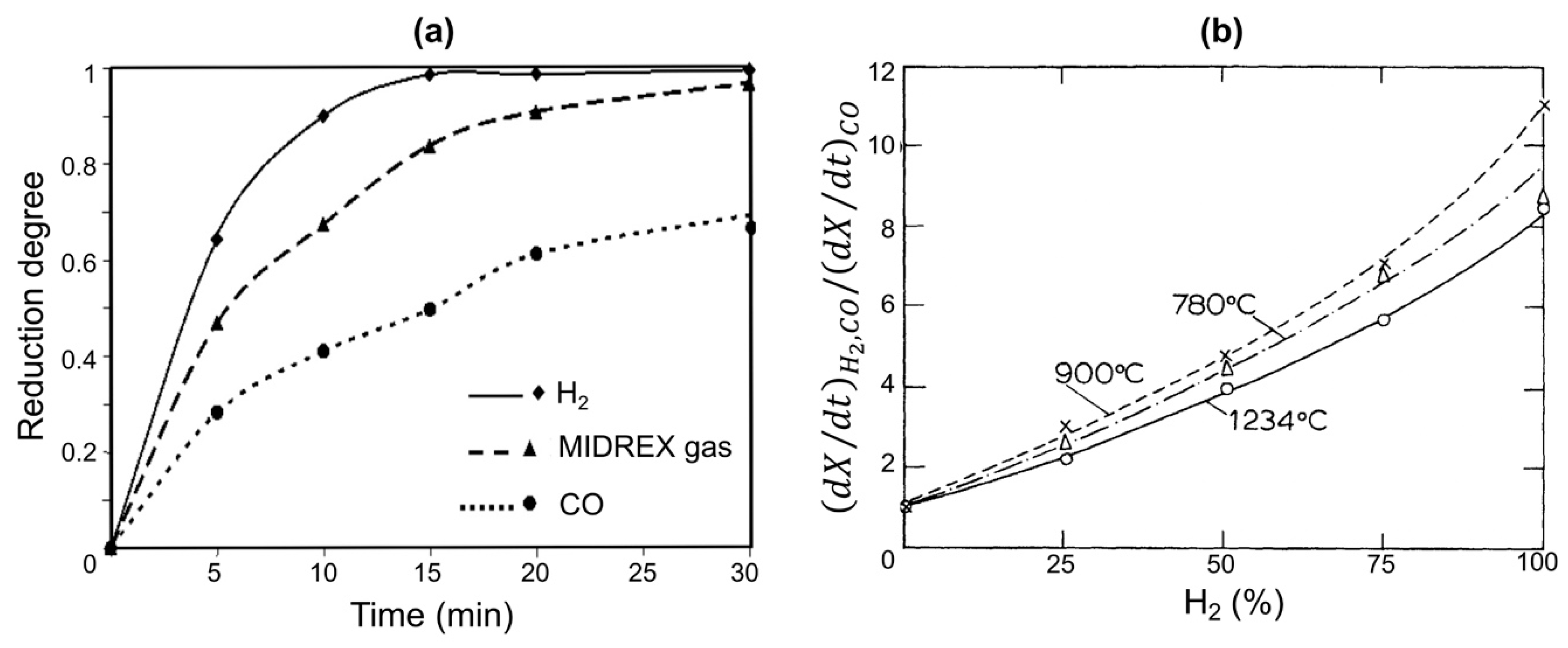
Regarding kinetics, laboratory studies on the reduction of iron oxides with CO, H2, and CO–H2 mixtures have clearly shown that, all else being equal, the kinetics with H2 are faster (up to 10 times) than those with CO [22,25,26], as illustrated below (Figure 9).
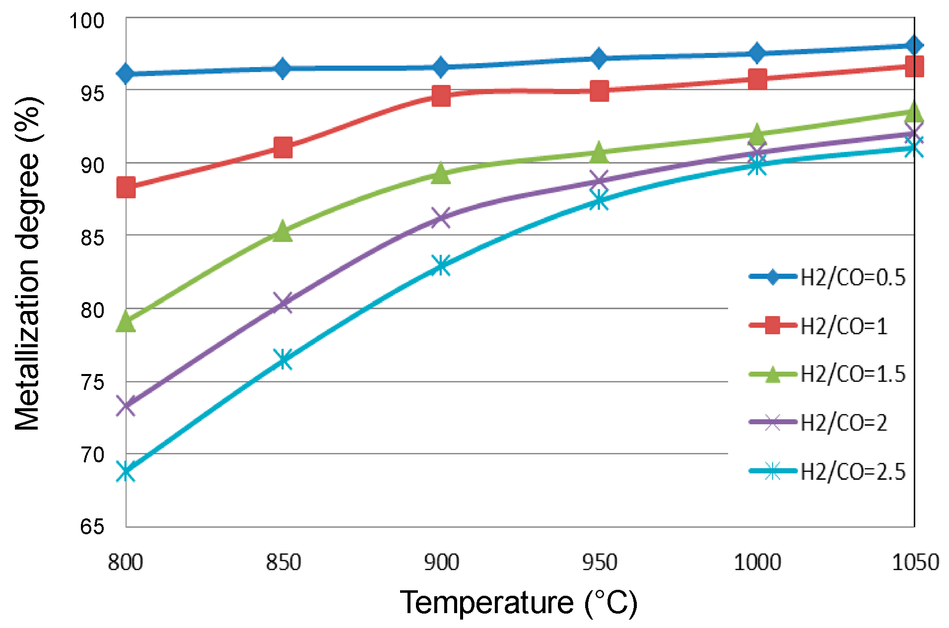
However, such laboratory experiments do not integrate the influence of thermal and thermodynamic characteristics, since the experiments are generally performed in isothermal conditions and without the presence of CO2 or H2O in the gas and are thus far from equilibrium. In all the current iron ore reduction processes, H2 and CO are present together, and both contribute to the reduction. Their utilization in the reduction reaction depends not only on their relative concentrations but also on the temperature and the reactor configuration. We carried out simulations of a MIDREX shaft furnace using different H2/CO ratios at the reducing gas inlet [27]. Figure 10 shows that the higher the H2 content is, the lower the metallization degree of the DRI, which at first glance is contrary to the kinetic behavior.
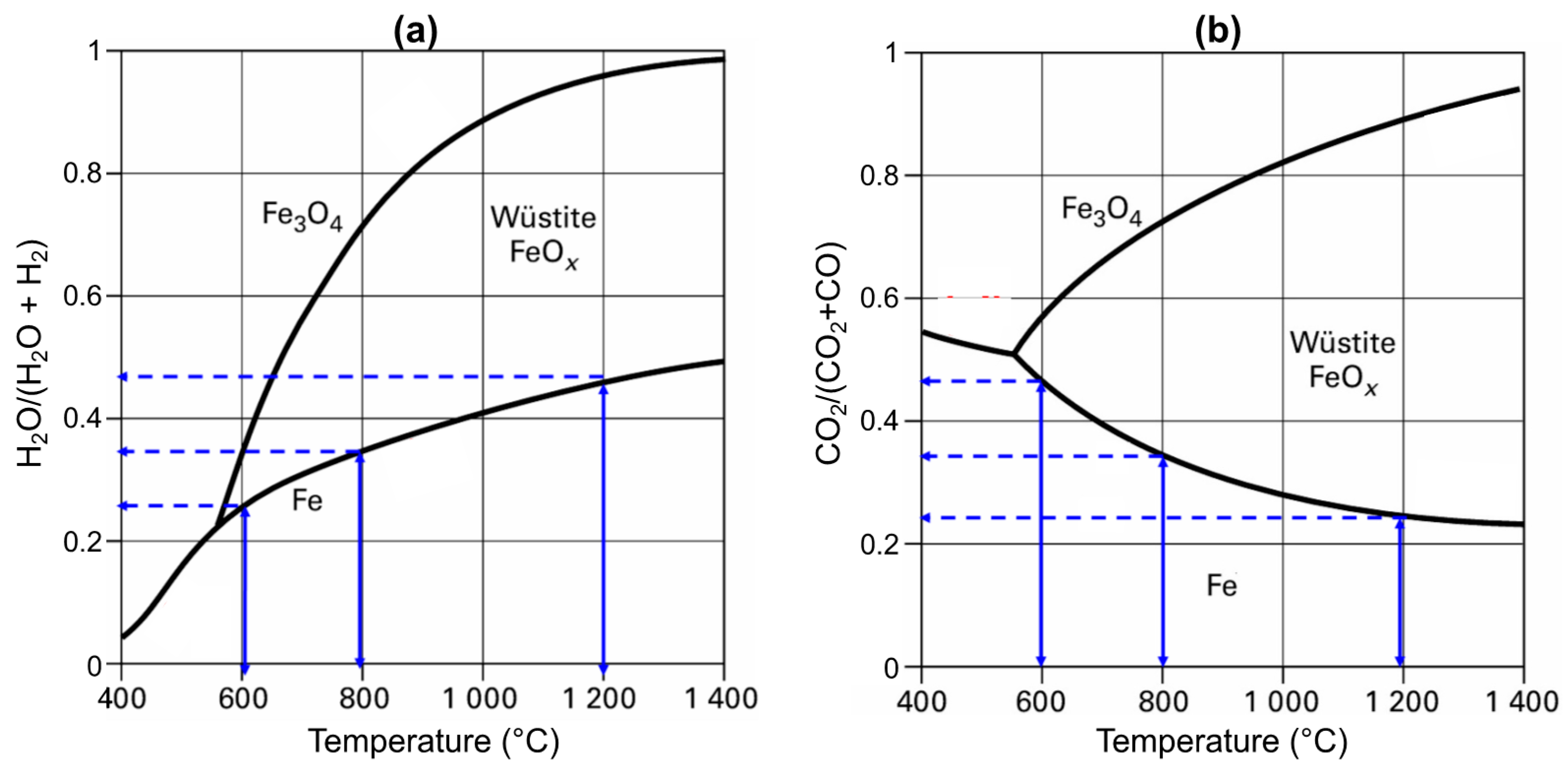
The explanation for this contradiction relies on several factors. The first is the thermodynamics, which favor CO at low temperatures, as evidenced by the Chaudron diagram (Figure 11). The vertical blue arrows represent the driving force for the wustite-to-iron reduction, which increases with temperature with H2 and decreases with temperature with CO.
The second factor is the heat of the reduction reactions (Table 4). The hematite-to-magnetite reaction is less exothermic with H2 than with CO, the magnetite-to-wustite reaction is more endothermic, and chiefly, the wustite-to-iron reaction is endothermic with H2 and exothermic with CO. Globally, the balance is an endothermic reduction with H2 and an exothermic reduction with CO.
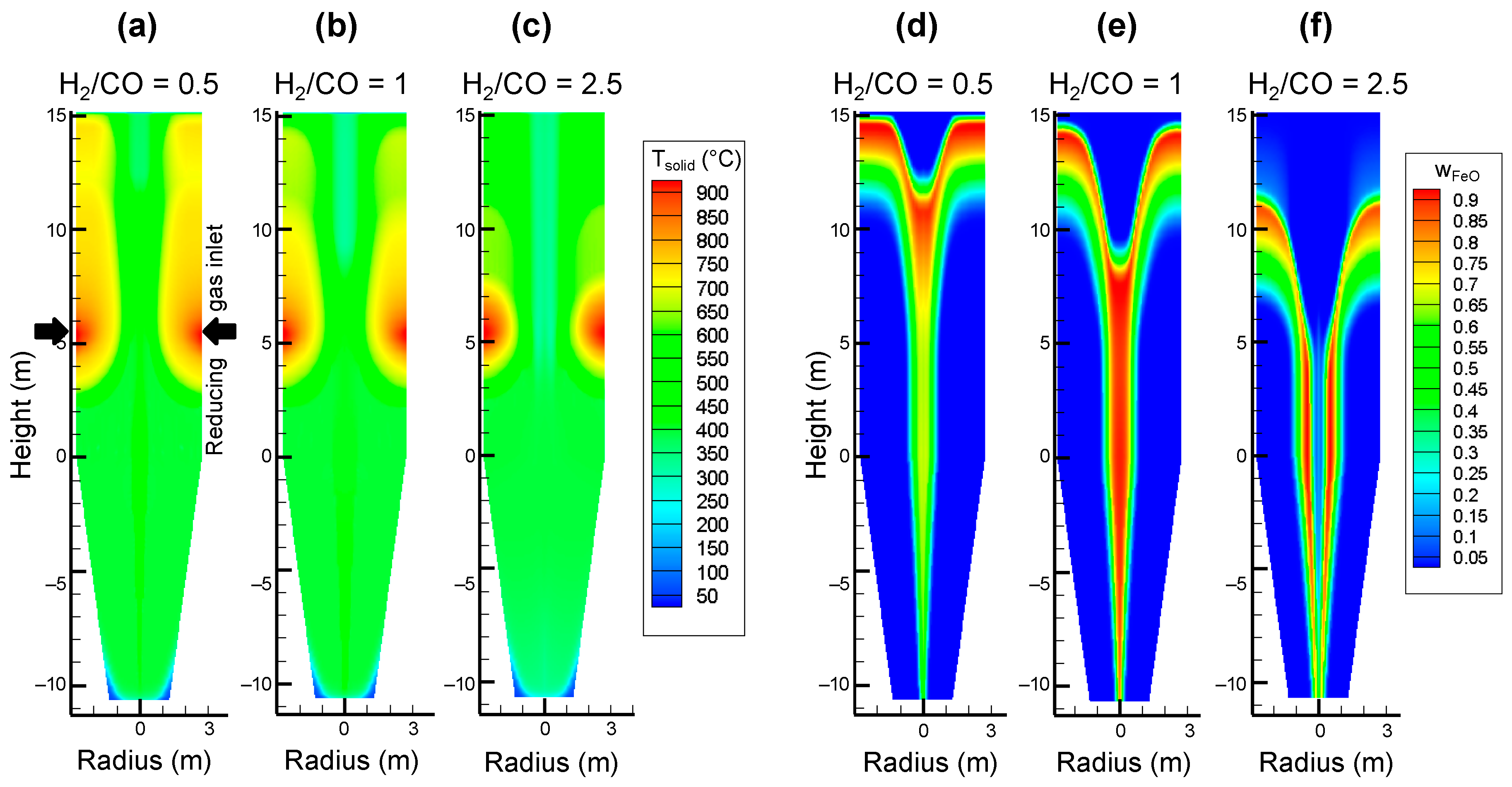
As a result, the temperature and compositions in the shaft greatly change with the inlet gas composition, as depicted by Figure 12. When leaving the gas injection zone, the temperature decreases due to methane cracking, but with a higher CO content, the bed is maintained at a higher temperature (a) as a result of the exothermic heat of the reduction reactions, whereas the temperature is lower with more H2 (c). Plots (d) and (e) show that the wustite reduction in the peripheral zone is completed in less than 5 m versus the 8 m in (f). In the central zone, the low temperature (due to the cooling effect of the methane rising from the cooling zone) hampers the reduction by H2 (thermodynamics), and wustite reduction in this zone is only possible by CO and thus goes further with more CO (d). Even if in all cases, more H2 than CO is globally utilized for the 3 reductions (a consequence of the kinetics), the latter effect, i.e., the reduction by CO in the central zone, is decisive regarding the final metallization degree, as noted in Figure 10.
Finally, recall that when using only H2 (both at the reducing gas inlet and at the bottom inlet) the colder central zone does not exist, the temperatures are more uniform radially, and the reduction, due to efficient kinetics, goes to completion (100% metallization).
6. Conclusions
In the context of reducing the CO2 emissions of steelmaking, the hydrogen-based route is currently receiving much attention. This paper presented the principles and characteristics of this breakthrough steelmaking route from the plant scale to the granular scale. As replacements for coal, coke, and gas, hydrogen can be used for ironmaking, and electricity can be used for steelmaking. The expected CO2 emissions of this new route would be reduced by 89–99% compared to those of the current blast furnace-basic oxygen furnace route.
Hydrogen production needs to be fossil-free, and thus, the appropriate production method is water electrolysis with CO2-lean electricity, i.e., renewable or nuclear electricity. Although water electrolysis is a well-known technology, some developments are needed to reach the target of massive amounts of CO2-lean and, above all, affordable hydrogen for ironmaking. Some projects have been launched by the steelmaking industry, but other projects could emerge from other sectors, such as the transportation and power industries.
Regarding the core process of this new route, the reduction of iron ore by hydrogen, we selected direct reduction in a shaft furnace similar to the MIDREX and HYL-ERNERGIRON reactors. First, compared to other breakthrough technologies with similar levels of CO2 mitigation, such as the direct electrolysis of iron ore, this process is much closer to industrialization, since the current DR shaft furnaces already work with H2-CO mixtures that “only” need to be replaced with 100% H2. Moreover, a DR plant using only hydrogen would be much simpler than MIDREX and HYL-ERNERGIRON, because the gas loop is shorter and methane reforming is not required. Third, compared to fluidized bed processes, it has the advantage of being able to treat lump ores and pellets, not fines. Finally, compared to intermediate options, such as the partial use of hydrogen in a blast furnace, it results in much higher CO2 mitigation.
Downstream, the steelmaking occurs in an electric arc furnace, as is currently practiced for making steel from scrap and from DRI. The only difference is that the hydrogen-produced DRI would be 0% carbon instead of the usual 2–4% content. Although real technical difficulties are not anticipated, as some carbon will be added in the EAF, this point merits experimental confirmation.
From the mathematical modeling of the reduction zone of a shaft furnace operated with 100% H2, we found that, due to the fast reduction kinetics with H2, complete metallization could theoretically be achieved faster than that with H2-CO, opening avenues to reactors smaller than the current DR shafts. The results have to be verified experimentally, which will be possible in some of the planned demonstrators [1]. Further work should also be performed to precisely determine the reactor geometry and dimensions, the configuration of the cooling section, and the details of the recycling gas loop, as well as to optimize the operating conditions for the selected configuration. Mathematical models such as REDUCTOR could be helpful.
Such mathematical reactor models rely on a proper evaluation of the reduction reaction kinetics at the pellet scale as a function of the temperature and local gas composition. Much knowledge has been acquired so far. Three reactions successively take place in grains but can coexist at the pellet scale. The last reaction is the slowest, and at approximately 700 and 950 °C, a final slowing can be observed. We proposed a pellet kinetic model based on the structural pellet and grain evolution in the course of the reaction, which very satisfactorily simulates the reduction up to 900 °C but could be further improved for higher temperatures.
Finally, the main differences between iron oxide reduction with H2 and that with CO were discussed. At the scale of a pellet, the kinetics are faster with H2. At the scale of a MIDREX shaft furnace using a H2-CO-CH4 mixture, due to the roles of thermodynamics, thermal gradients, and gas flow effects, CO plays a decisive role by better reducing wustite in the colder central zone. Using only H2, the temperature and composition profiles are flatter and full metallization is predicted.
Author Contributions
Conceptualization, F.P. and O.M.; methodology: F.P. and O.M.; investigation: F.P. and O.M.; writing: F.P. and O.M.; supervision: F.P. and O.M.; Project Administration and Funding Acquisition: F.P. All authors have read and agreed to the published version of the manuscript.
Funding
Most of this research was supported by the European Commission within the 6th Framework Programme, project No: 515960 ULCOS (Ultra-low CO2 steelmaking).
Acknowledgments
Conflicts of Interest
The authors declare no conflict of interest.
References
- Hybrit (Hydrogen Breakthrough Ironmaking Technology) Brochure. Available online: https://ssabwebsitecdn.azureedge.net/-/media/hybrit/files/hybrit_brochure.pdf (accessed on 28 April 2020).
- H2FUTURE. Verbund Solutions GmbH. Available online: https://www.h2future-project.eu (accessed on 28 April 2020).
- GrInHy. Green Industrial Hydrogen. Salzgitter Mannesmann Forschung GmbH. Available online: https://www.green-industrial-hydrogen.com (accessed on 28 April 2020).
- ArcelorMittal. Hydrogen-Based Steelmaking to Begin in Hamburg. Available online: https://corporate.arcelormittal.com/media/case-studies/hydrogen-based-steelmaking-to-begin-in-hamburg (accessed on 28 April 2020).
- Hydrogen Scaling Up. The Hydrogen Council. Available online: https://hydrogencouncil.com/wp-content/uploads/2017/11/Hydrogen-scaling-up-Hydrogen-Council.pdf (accessed on 28 April 2020).
- European Commission. Energy Efficiency and CO2 Reduction in the Iron and Steel Industry. Available online: https://setis.ec.europa.eu/system/files/Technology_Information_Sheet_Energy_Efficiency_and_CO2_Reduction_in_the_Iron_and_Steel_Industry.pdf (accessed on 28 April 2020).
- Yilmaz, C.; Jens Wendelstorf, J.; Turek, T. Modeling and simulation of hydrogen injection into a blast furnace to reduce carbon dioxide emissions. J. Clean. Prod. 2017, 154, 488–501. [Google Scholar] [CrossRef]
- Vogl, V.; Ahman, M.; Nilsson, L.J. Assessment of hydrogen direct reduction for fossil-free steelmaking. J. Clean. Prod. 2018, 203, 736–745. [Google Scholar] [CrossRef]
- Molten Oxide Electrolysis. Boston Metals. Available online: https://www.bostonmetal.com/moe-technology (accessed on 28 April 2020).
- Siderwin. Development of New Methodologies for Industrial CO2-Free Steel Production by Electrowinning. Available online: https://www.siderwin-spire.eu/content/objectives (accessed on 28 April 2020).
- Abdul Quader, M.; Ahmed, S.; Dawal, S.Z.; Nukman, Y. Present needs, recent progress and future trends of energy-efficient Ultra-Low Carbon Dioxide (CO2) Steelmaking (ULCOS) program. Renew. Sustain. Energy Rev. 2016, 55, 537–549. [Google Scholar] [CrossRef]
- Plaul, F.J.; Böhm, C.; Schenk, J.L. Fluidized-bed technology for the production of iron products for steelmaking. J. S. Afr. Inst. Min. Metall. 2009, 108, 121–128. [Google Scholar]
- Nuber, D.; Eichberger, H.; Rollinger, B. Circored fine ore direct reduction-the future of modern electric steelmaking. Stahl und Eisen 2006, 126, 47–51. [Google Scholar]
- Birat, J.P. Society, materials, and the environment: The case of steel. Metals 2020, 10, 331. [Google Scholar] [CrossRef] [Green Version]
- Wagner, D. Etude Expérimentale et Modélisation de la Réduction du Minerai de fer par L’Hydrogène. Ph.D. Thesis, Institut National Polytechnique de Lorraine, Nancy, France, 2008. Available online: https://tel.archives-ouvertes.fr/tel-00280689/ (accessed on 28 April 2020).
- Parisi, D.R.; Laborde, M.A. Modeling of counter current moving bed gas-solid reactor used in direct reduction of iron ore. Chem. Eng. J. 2004, 104, 35–43. [Google Scholar] [CrossRef] [Green Version]
- Valipour, M.S.; Saboohi, Y. Numerical investigation of nonisothermal reduction of haematite using syngas: The shaft scale study. Model. Simul. Mater. Sci. Eng. 2007, 15, 487–507. [Google Scholar] [CrossRef]
- Shams, A.; Moazeni, F. Modeling and Simulation of the MIDREX Shaft Furnace: Reduction, Transition and Cooling Zones. JOM 2015, 67, 2681–2689. [Google Scholar] [CrossRef]
- Hamadeh, H.; Mirgaux, O.; Patisson, F. Detailed Modeling of the Direct Reduction of Iron Ore in a Shaft Furnace. Materials 2018, 11, 1865. [Google Scholar] [CrossRef] [PubMed] [Green Version]
- Ranzani da Costa, A.; Wagner, D.; Patisson, F. Modelling a new, low CO2 emissions, hydrogen steelmaking process. J. Clean. Prod. 2013, 46, 27–35. [Google Scholar] [CrossRef] [Green Version]
- Ranzani da Costa, A. La Réduction du Minerai de fer par L’Hydrogène: Etude Cinétique, Phénomène de Collage et Modélisation. Ph.D. Thesis, Institut National Polytechnique de Lorraine, Nancy, France, 2011. Available online: https://tel.archives-ouvertes.fr/tel-01204934/ (accessed on 28 April 2020).
- Zare Ghadi, A.; Valipour, M.S.; Vahedi, S.M.; Sohn, H.S. A Review on the Modeling of Gaseous Reduction of Iron Oxide Pellets. Steel Res. Int. 2020, 91, 1900270. [Google Scholar] [CrossRef]
- Gransden, J.F.; Sheasby, J.S.; Bergougnou, M.A. Defluidization of iron ore during reduction by hydrogen in a fluidized bed. Chem. Eng. Progress Symp. Ser. 1970, 66, 208–214. [Google Scholar]
- Sohn, H.Y. The law of additive reaction times in fluid-solid reactions. Metall. Trans. 1978, 9B, 89–96. [Google Scholar] [CrossRef]
- Towhidi, N.; Szekely, J. Reduction kinetics of commercial low-silica hematite pellets with CO-H2 mixtures over temperatures range 600–1234 °C. Ironmak. Steelmak. 1981, 6, 237–249. [Google Scholar]
- Bonalde, A.; Henriquez, A.; Manrique, M. Kinetic analysis of the iron oxide reduction using hydrogen-carbon monoxide mixtures as reducing agent. ISIJ Int. 2005, 45, 155–1260. [Google Scholar] [CrossRef] [Green Version]
- Hamadeh, H. Modélisation Mathématique Détaillée du Procédé de Réduction Directe du Minerai de fer. Ph.D. Thesis, Université de Lorraine, Nancy, France, 2017. Available online: https://tel.archives-ouvertes.fr/tel-01740462 (accessed on 28 April 2020).
Figure 1.
ULCOS hydrogen-based route to steel.

Figure 2.
Principle of the REDUCTOR (v1) model; (a–d): the four scales considered.

Figure 3.
Main results of the shaft model. The calculations were performed under the conditions given in Table 1. Top row: solid mass fractions; bottom row: solid and gas temperatures, gas molar fractions in H2 and H2O. The symmetry axis is on the left-hand side of each map, and the wall is on the right-hand side. The main gas inlet is at the wall near the bottom of the reactor.

Figure 4.
Calculated influence of the inlet gas temperature on the iron mass fraction.

Figure 5.
Kinetics of iron ore pellet reduction by H2 plotted as a TTT diagram.

Figure 6.
SEM micrographs showing the morphological changes at the granular scale in CVRD-DR pellets; (a–e): iron grains after reduction at different temperatures; (f–j): grains in different stages of a reduction at 800 °C; (k–n): polished cross-sections at conversion degrees of 65% (k,l) and 81% (m,n) for samples reduced at 900 °C, the red arrows point to shrinking wustite cores (dark gray) surrounded with a spreading layer of iron (light gray), indicated by the blue arrows. All images were taken with SE (secondary electrons), except (l) and (n), which were taken with BSE (backscattered electrons). The gas used for the reduction was 2 L/min H2-He (60–40 vol. %) in a thermobalance.

Figure 7.
Modeled representation of the pellet (top row) and grain (bottom row) evolution.

Figure 8.
Results of the single pellet model; (a): calculated solid fractions as a function of time; (b): comparison with experimental data at various temperatures for a CVRD-DR pellet reduced by 2 L/min of H2-He (60–40 vol. %) in a thermobalance.
Figure 8.
Results of the single pellet model; (a): calculated solid fractions as a function of time; (b): comparison with experimental data at various temperatures for a CVRD-DR pellet reduced by 2 L/min of H2-He (60–40 vol. %) in a thermobalance.

Figure 9.
Comparison of the reduction kinetics of hematite pellets with H2, CO, and H2-CO mixtures. (a): reduction curves at 850 °C (the MIDREX gas contains approx. 56%H2 and 34% CO), data from [26]; (b): relative reduction rates at 55% conversion at 780, 900 and 1234 °C as a function of the H2 content in the H2-CO mixture, data from [25].

Figure 10.
Metallization degree of the DRI at the exit of a MIDREX shaft furnace as a function of temperature and H2/CO ratio.
Figure 10.
Metallization degree of the DRI at the exit of a MIDREX shaft furnace as a function of temperature and H2/CO ratio.

Figure 11.
Chaudron (or Baur-Glaessner) phase diagram of the iron phase domains as a function of the temperature and oxidizing power of the gas, (a) in the case of a H2-H2O atmosphere and (b) CO-CO2 atmosphere. The vertical blue arrows represent the driving force for the wustite-to-iron reduction.
Figure 11.
Chaudron (or Baur-Glaessner) phase diagram of the iron phase domains as a function of the temperature and oxidizing power of the gas, (a) in the case of a H2-H2O atmosphere and (b) CO-CO2 atmosphere. The vertical blue arrows represent the driving force for the wustite-to-iron reduction.

Figure 12.
Calculated solid temperature (a–c) and iron mass fraction (d–f) throughout a shaft furnace fed with different inlet reducing gas compositions: H2/CO = 0.5 (a,d), H2/CO = 1 (b,e), H2/CO = 2.5 (c,f), the other species being CH4 (9%), H2O (4%) and CO2 (2%).
Figure 12.
Calculated solid temperature (a–c) and iron mass fraction (d–f) throughout a shaft furnace fed with different inlet reducing gas compositions: H2/CO = 0.5 (a,d), H2/CO = 1 (b,e), H2/CO = 2.5 (c,f), the other species being CH4 (9%), H2O (4%) and CO2 (2%).


Table 1.
Energy and CO2 emissions of various steelmaking routes.
| Route | Energy Needed | CO2 Emissions | ||
|---|---|---|---|---|
| Standard BF-BOF route | 18.8 GJ/tHRC (mostly coal) | [14] | 1850 kgCO2eq/tHRC | [14] |
| Direct reduction + EAF | 15.6 GJ/tHRC (gas and electricity) | [14] | 970 kgCO2eq/tHRC | [14] |
| Hydrogen-based route | 15.4 GJ/tHRC | [15] | 196 kgCO2eq/tHRC | [15] |
| 14.7 GJ/tLS (mostly electricity) | [1] | 25 kgCO2eq/tLS | [1] | |
| 13.3 GJ/tLS | [8] | 53 kgCO2eq/tLS | [8] | |
Abbreviations: BF: blast furnace; BOF: basic oxygen furnace; HRC: hot rolled coil; EAF: electric arc furnace; LS: liquid steel.
Table 2.
Main operating conditions for the reference simulation.
| Shaft | Height = 6 m | Radius = 3.3 m | |
| Pellets | CVRD-DR | Diameter = 14 mm | Porosity = 0.33 |
| Inlet solid | Fe2O3 | Flowrate = 52 kg s−1 | Temperature = 25 °C |
| Inlet gas | 98%H2, 2%H2O | Lateral flowrate = 3634 mol s−1 Bottom flowrate = 100 mol s−1 | Temperature = 800 °C |
Table 3.
Publications on the reduction of iron oxides from 1900 to 2020.
| Search Terms | Number of Papers |
|---|---|
| iron (oxide or ore) reduction | 20,230 |
| iron (oxide or ore) reduction CO | 3692 |
| iron (oxide or ore) reduction H2 | 109 |
| iron (oxide or ore) mechanisms | 792 |
| iron (oxide or ore) kinetics | 741 |
Source: ISI Web of Science, accessed on 18 May 2020.
Table 4.
Heat values of the reduction reactions. A minus sign indicates an exothermic reaction.
| Reaction | ∆rH800 °C (J mol−1) |
|---|---|
| −6020 | |
| −40,040 | |
| 46,640 | |
| 18,000 | |
| 16,410 | |
| −17,610 |
© 2020 by the authors. Licensee MDPI, Basel, Switzerland. This article is an open access article distributed under the terms and conditions of the Creative Commons Attribution (CC BY) license (http://creativecommons.org/licenses/by/4.0/).
Share and Cite
MDPI and ACS Style
Patisson, F.; Mirgaux, O. Hydrogen Ironmaking: How It Works. Metals 2020, 10, 922. https://doi.org/10.3390/met10070922
AMA Style
Patisson F, Mirgaux O. Hydrogen Ironmaking: How It Works. Metals. 2020; 10(7):922. https://doi.org/10.3390/met10070922
Chicago/Turabian StylePatisson, Fabrice, and Olivier Mirgaux. 2020. "Hydrogen Ironmaking: How It Works" Metals 10, no. 7: 922. https://doi.org/10.3390/met10070922
Note that from the first issue of 2016, this journal uses article numbers instead of page numbers. See further details here.