Article

Evolution of the Fretting Wear Damage of a Complex Phase Compound Layer for a Nitrided High-Carbon High-Chromium Steel

School of Mechanical and Automotive Engineering, South China University of Technology, Guangzhou 510640, China
*
Author to whom correspondence should be addressed.
Metals 2020, 10(10), 1391; https://doi.org/10.3390/met10101391
Submission received: 29 September 2020 / Revised: 11 October 2020 / Accepted: 14 October 2020 / Published: 19 October 2020
(This article belongs to the Special Issue Machinability and Tribological Performance of Advanced Alloys)

Abstract

:
In this paper, the X210CrW12 steel was subjected to gas nitriding to obtain a complex phase compound layer with limited porosity. The nitrided layer was characterized by scanning electron microscopy (SEM), energy dispersive spectroscopy (EDS) and X-ray diffraction (XRD). The fretting wear behavior and the evolution of fretting wear damage of the compound layer were studied, and the worn surfaces were characterized by SEM/EDS and 3D optical profilometry. The results indicated that the compound layer showed superior fretting wear resistance and sufficient load-carrying capacity in the low loading case of 35 N, but the fracture of coarse nitrides (transformed primary carbides) was obviously detrimental to wear resistance. For the high loading case of 70 N, the low toughness of the compound layer led to the occurrence of brittle cracks, and the decrease in the thickness of the compound layer due to wear resulted in the cracking and spalling of the compound layer.

1. Introduction

Gas nitriding, as a typical thermo-chemical surface treatment, is one of the most efficient methods to enhance the surface properties, such as surface hardness, corrosion and wear resistance [1,2,3,4,5,6,7,8]. The typical nitrided layer consists of two different structures, known as the compound layer and diffusion layer. Generally, the compound layer is composed of γ′-Fe4N, ε-Fe2–3N, or a mixed phase (ε + γ′). The diffusion layer brings about an improvement of the fatigue properties, whereas the improvement of wear and corrosion properties is ascribed to the compound layer [3].
There are three main types of compound layer. One type of layer consists of a predominant percentage of ε phase. Such a layer is very porous and its wear resistance is worsened [9,10]. However, the γ′ phase is more ductile than ε phase, but the compound layer consisting of monophase γ′ is usually thin and prone to spalling in heavy conditions due to the extremely hardness differences occurring between the compound layer and diffusion zone [11]. The next layer consists of γ′ + ε iron nitrides with a limited percentage of ε phase. Investigations show that if the porosity in this type of compound layer can be well controlled, the compound layer with a relative reasonable thickness is very beneficial to the wear and corrosion resistance in many cases [12,13,14,15]. In practice, the complex phase compound layers (with limited porosity) are widely applied in non-impact conditions to improve the resistance to damage affecting the component life such as wear and corrosion. Further, the sliding wear characteristics of this type of compound layer have been extensively studied [4,5,6,7,11,12,13,16,17,18]. As reported by Rad et al. [17], the specimens with a good thickness compound layer had a lower wear rate, but the thin compound layer was broken in small sliding distance, resulting in a high wear rate. In the paper [18], the sliding wear test of the nitrided specimens was carried out on a ball-on-disc machine under loads of 100 and 300 N, and the GCr15 steel ball (with a hardness of 63–65 HRC) was used as the counterbody material. The results showed that the compound layer consisting of γ′ + ε phases showed excellent wear resistance under the light load of 100 N, but poor wear properties at the heavy load of 300 N.
Fretting wear, which is caused by the vibration of the mechanical system or the variation in loads, is found to be different from the sliding wear [19] due to the small displacement amplitude, and the material loss caused by it is much less than that caused by sliding wear. However, fretting wear can produce a loss of fitting and degrade the functionality of the mechanical system. The degradation of the component surface caused by fretting wear is the result of several wear mechanisms, such as abrasion, adhesion, crack and oxidation [20]. Although many experimental works have been carried out to study the sliding wear behavior of the compound layer, there is a lack of knowledge relating to the fretting wear behavior. Identification of the evolution of fretting wear damage of the compound layer is crucial to ensure stable service of the nitrided components.
In this study, the X210CrW12 steel was selected as the experiment material. It is a very hard material with high wear-resistance and can be widely used in tribological applications [21]. The material was subjected to gas nitriding to obtain a complex phase compound layer with limited porosity, and the fretting wear behavior and the evolution of fretting wear damage of the compound layer were analyzed in detail.

2. Materials and Methods

2.1. Material Preparation and Nitriding Treatment

The chemical composition (wt.%) of X210CrW12 steel used in this study is shown in Table 1. The discs with a diameter of 40 mm and thickness of 11 mm were cut from a bar received in the annealed condition. Before nitriding, specimens were austenitized at 1080 °C for 30 min followed by oil quenching, then triple tempered at the temperature of 580 °C for 2 h, leading to a hardness of 495 ± 15 HV0.2. After the heat treatment, the thickness of all specimens was machined to 8 mm to remove the decarburized layer. Prior to the gas nitriding process, all specimens were ground with SiC abrasive papers of 600, 1200, 1500 and 2000 grits followed by mirror polishing, and ultrasonically cleaned in acetone for 10 min. Then, all specimens were hung in a gas nitriding furnace. Gas nitriding was performed using an industrial unit at 500 °C for nearly 70 h, and the high-purity NH3 gas was used as the nitriding medium.

2.2. Fretting Wear Test and Microstructure Characterization

Fretting wear tests were performed on an Optimol SRV IV (DIN51834, SRV, Optimol, Munchen, Germany) reciprocating friction and wear test machine under the dry condition at a temperature of 25 °C. The ball-on-flat method was adopted to perform the test, as illustrated in Figure 1. The upper ball specimen (SiC ball with a hardness of about 2600 HV) with a diameter of 10 mm was mounted in a holder attached to an oscillating electro-mechanical drive, and pressed against the stationary lower specimen (nitrided specimen). In addition, load, frequency and amplitude conditions were chosen for best test stability. The fretting wear tests were carried out under the load of 35 N and 70 N, because the fretting wear behavior of the nitrided samples under these two load conditions was representative. In order to study the evolution of fretting wear damage, the fretting cycle ranged from 24 × 103 to 72 × 103. Each test was repeated at least three times to check the repeatability. The main test parameters are listed in Table 2. After each fretting wear test, the specimens were ultrasonically cleaned for 15 min, thus leaving any debris that was more firmly adhered to the worn surface.
The cross-sectional microstructure of nitrided specimen and the fretting wear mechanism was studied by scanning electron microscopy using backscattered electron mode (SEM/BSE; Quanta 200 & Nova nanosem 430, FEI, Hillsboro, OR, USA). The microhardness of the nitrided specimen was measured using a Vickers microhardness tester (HDV-10002, SCTMC, Shanghai, China) with a load of 1.96 N and a holding time of 15 s. Phase composition of the un-nitrided and nitrided specimens was studied by X-ray diffraction (XRD; D8 Advance, Bruker-axs, Karlsruhe, Germany). The surface topography of wear scar was characterized by mean of a 3D optical profiler (America RTEC Up Dual-Mode), and the depth and volume of the wear scar were obtained by the instrument software.

3. Results and Discussion

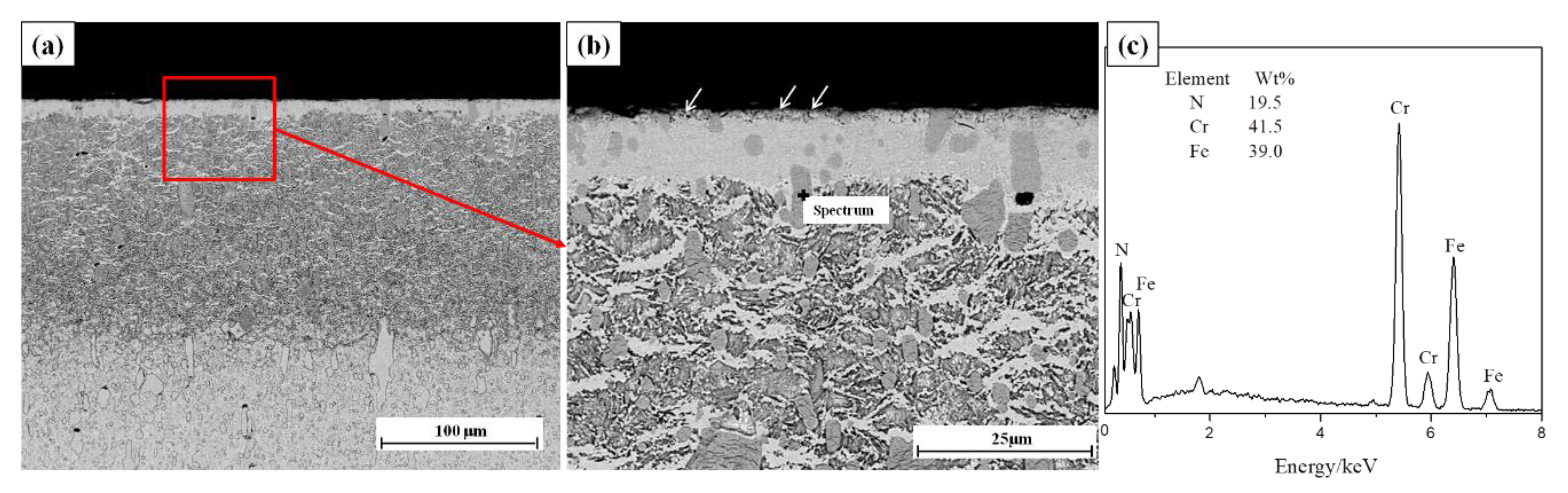
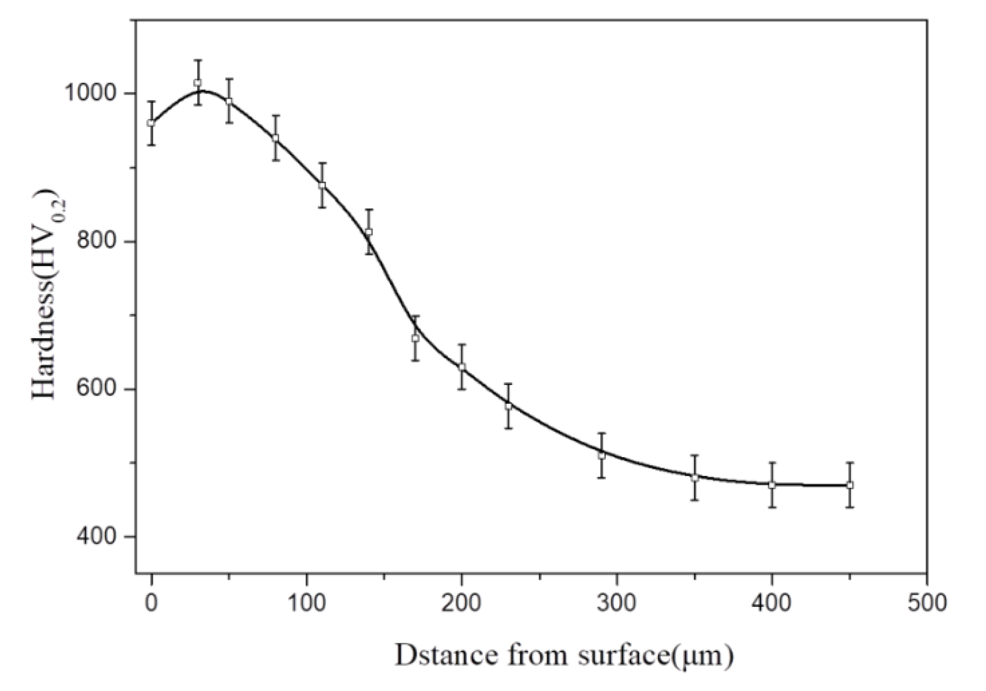
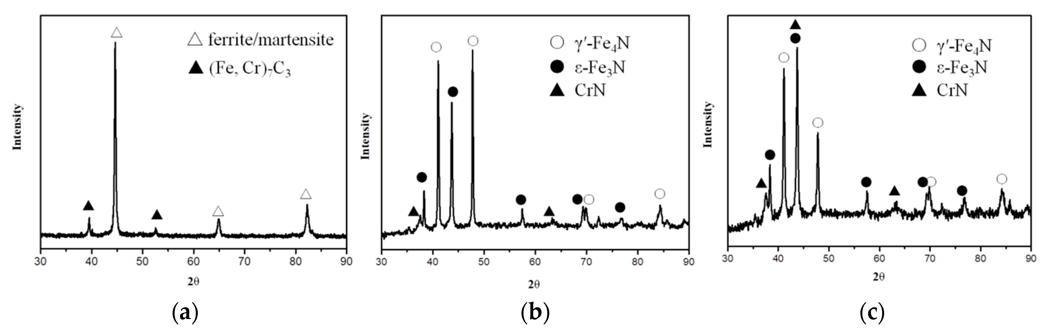
3.1. Microstructural Characteristics

Figure 2 shows the cross-sectional microstructure of the nitrided layer. It can be found that the primary and secondary alloy carbides are dispersed throughout the base material. These phases represent the main microstructural characteristics of X210Crw12 steel. During nitriding, these initial carbides will be transformed into nitrides [22,23], as confirmed by the results of EDS analysis (Figure 2c), and the released carbon atoms will diffuse (i) toward the nitrogen diffusion front, forming the cementite precipitates along grain boundaries, and (ii) toward the outer surface, leading to decarburization of the surface adjacent region [23]. Figure 2b clearly shows that the compound layer is a compact layer, and the thickness of the compound layer was measured to be in the range of about 8–10 μm. However, small pores formed on the top surface of the compound layer, as shown with arrows. Figure 3 shows the cross-sectional microhardness profile of the nitrided specimen. After nitriding, the surface hardness is 960 ± 30 HV0.2, which was measured after the removal of pores on the top surface of the compound layer. The decrease in the surface hardness may be caused by the occurrence of decarburization in the surface adjacent regions [23] or the long nitriding time [12,23].
Figure 4 shows the X-ray diffraction patterns on the surface of the un-nitrided and nitrided specimens. Before nitriding, the substrate is characterized by ferrite (tempered martensite) and (Cr, M)7C3 carbide diffraction patterns (Figure 4a). After nitriding, the presence of the γ′ (Fe4N) and ε (Fe3N) phases, together with the CrN phase can be identified (Figure 4b), confirming the formation of the compound layer constituted by these phases. Then, the nitrided specimen was polished to remove the pores on the top surface of the compound layer. Figure 4c shows the XRD phase analysis of the compound layer after polishing. It can be found that after polishing, the peak intensity of ε phase becomes stronger, while the intensity of γ′ phase peak becomes weak. Therefore, the existence of ε phase should not be responsible for the formation of pores on the top surface of the compound layer. The reason for the formation of pores and the increase in the amount of γ′ phase at the top surface of the compound layer may be due to the occurrence of decarburization in this region [24]. As estimated from the intensities of the respective diffraction lines (Figure 4c), the ratio of ε/γ′ for the compound layer is about 1.3, which provides high hardness for the compound layer and makes its porosity be well controlled.

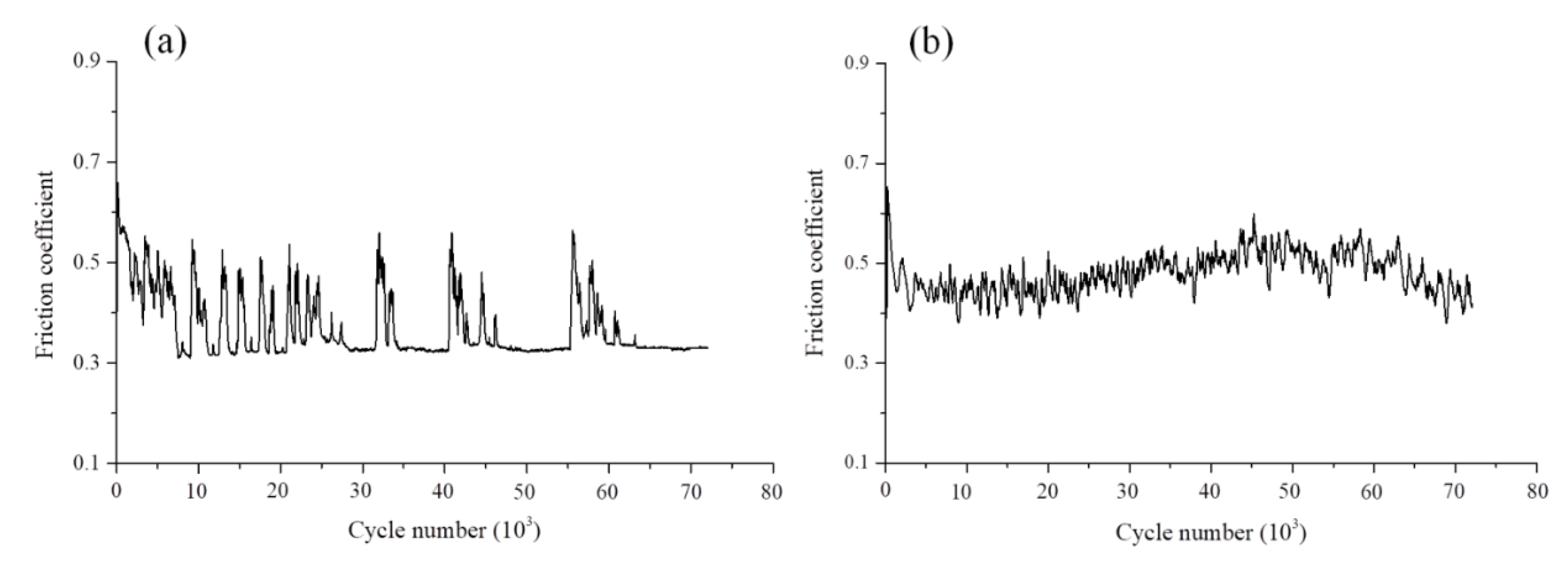
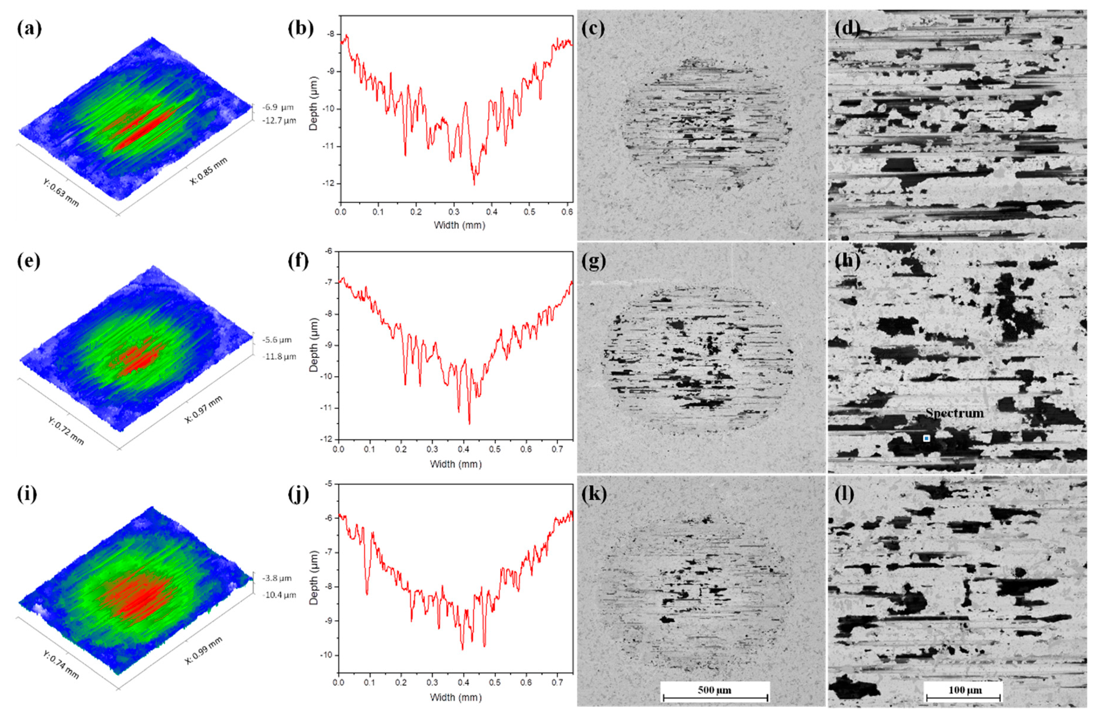
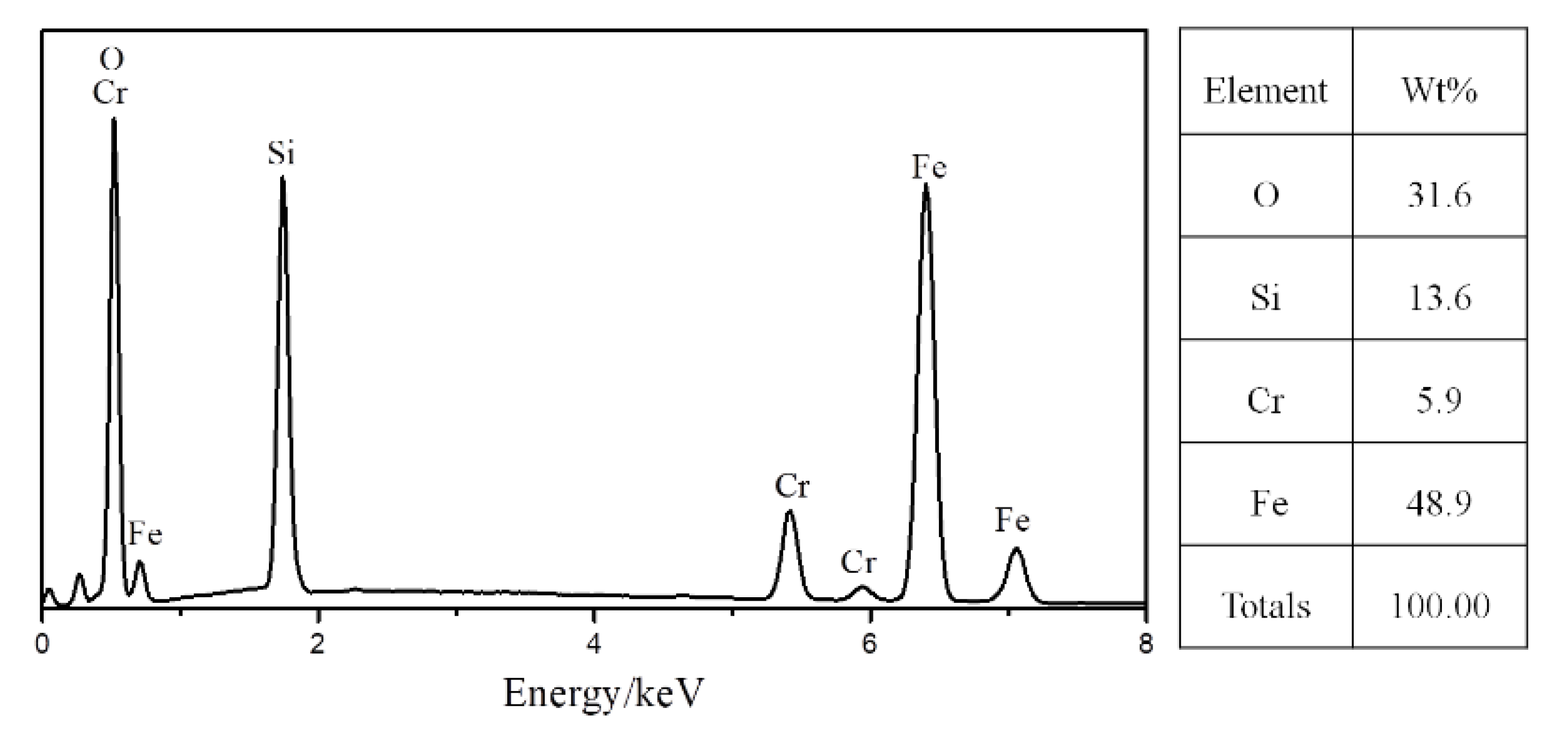
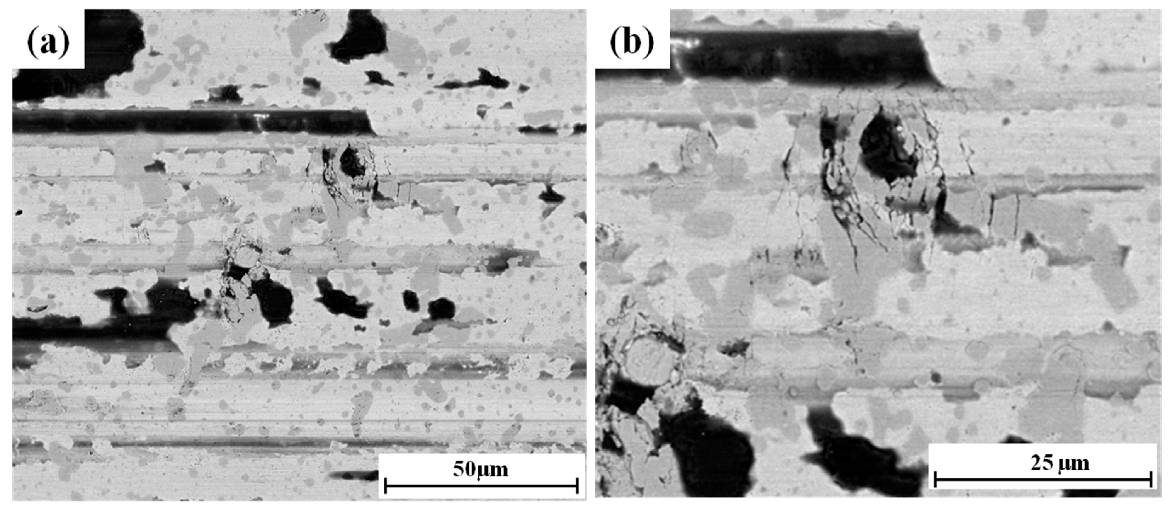
3.2. Fretting Wear Behavior

Figure 5 plots the evolution of the friction coefficient for 72 × 103 fretting cycles under the two loading conditions. In the loading case of 35 N, the friction coefficient varies very much in the initial 24 × 103 cycles, and then gets to a steady state with a small value of around 0.32. However, it is worth noting that the friction coefficient can increase rapidly at a certain time, and then decreases gradually to the stable value again. Under the normal load of 70 N, the frictional coefficient curve shows different characteristics from that in the loading case of 35 N. The friction coefficient varies very much throughout the whole wear process, and the average friction coefficient is 0.45, which is higher than that in the loading case of 35 N. This finding is in contrast with the results reported by many other investigators [25,26]. In their work, the friction coefficient decreased with increasing the normal load, which was proposed to be due to the fact that the surface contact was the elastic contact which resulted in the asperities interlock in the low loading case [26].
Figure 6 illustrates the wear volume of the nitrided specimens as a function of cycle number. For the two loading conditions, the wear volume increases with the number of cycles as expected. However, for the loading case of 35 N, it can be seen that the wear rate rapidly decreases to a very low value after the initial 24 × 103 cycles. When the fretting cycle increases from 24 × 103 to 72 × 103 the wear volume increases slowly from 0.62 × 10⁻³ mm3 to 0.82 × 10⁻³ mm3. Under the normal load of 70 N, the wear volume shows a different trend compared to that under the load of 35 N, it increases almost linearly with increasing the fretting cycle.
Figure 7 shows the 3D surface morphologies and BSE images of the wear scars after different fretting cycles under the normal load of 35 N. The 3D surface morphologies show that the worn surfaces are dominated by the deep grooves parallel to the sliding direction, suggesting that the main wear mechanism is two-body abrasive wear. Furthermore, it can be seen that wear depth in the central region of the wear scars is maximum, which is proposed to be caused by the Hertzian contact pressure distribution. However, the wear area and depth increase slowly with the increasing number of cycles. From the SEM-BSE images of the wear scars, it can be seen that the worn surfaces for different cycle’s tests show similar wear characteristics with some dark areas. EDS analysis of the dark area (point in Figure 7h) is shown in Figure 8, revealing that the dark area is oxidized wear debris consisting mainly of O, Fe and Si. These indicate that the abrasive particles generated from the wear of the nitrided specimens and SiC balls were oxidized, and material transfer from the balls to the worn surfaces occurred.
Figure 9 shows the worn surface at the center of the wear scar after 72 × 103 cycles. Some cracks can be observed on the worn surface, resulting from the fracture of coarse nitrides (transformed primary carbides) (Figure 9a). Under the high-frequency reciprocating sliding conditions, the cyclic stresses and local concentrated stresses were imposed, leading to the cracking of coarse nitrides due to their low toughness, and to their removal as fragments, leaving deep cavities on the worn surface (Figure 9a). Figure 9b clearly shows that cracks are observed around the broken coarse nitride, suggesting that the interfaces of the transformed primary carbides and matrix are the potential sites for the initiation as well as the propagation of cracks. It becomes clear that these transformed primary carbides are obviously detrimental to wear resistance in this situation. These observations are consistent with the work of Singh et al. [27] who studied the wear behavior of AISI D2 steel in two-body abrasive wear and stated that when the induced stress exceeded the fracture strength of primary carbides, the carbides fractured due to their low ductility, and the fracture and exfoliation of the primary carbides were the dominating factors affecting the wear resistance of the material. It can be observed that apart from the fracture of the coarse nitrides, brittle cracks or metallic ribbons ready to detach can be hardly observed in the matrix (Figure 9a), indicating that this type of compound layer shows good toughness and wear resistance in this loading case.
In all cases, the wear process itself can lead to a reduction of contact pressure due to the increased area of contact, subsequently resulting in the decrease in wear rate, as predicted by the literature [28] which presented the macroscopic wear process using the finite element analysis (FEA). On the other hand, the oxide layer formed on the worn surfaces should be responsible for the very low wear rate in this loading case, because it acted as a lubricating film during the wear process [29,30], which favoured the wear resistance and decreased the wear rate and friction coefficient.
The friction coefficient shows that there are two main wear mechanisms involved in the wear of the nitrided specimens during the wear progress (Figure 5a). During the early fretting cycles of about 24 × 103, the friction coefficient varies very much. At this stage, the dominant wear mechanism is abrasive wear, accompanied by the rapid removal of material, which is confirmed by the deep grooves on the worn surface (Figure 7a) and the high wear rate (Figure 6). The oxidation mechanism is also active (confirmed by the oxide layer on the worn surface as shown in Figure 7c and d), but it is not the primary wear mechanism. Then, as the fretting cycle continues to increase, the friction coefficient decreases to a small value of around 0.32, but it is worth noting that the friction coefficient can increase rapidly at a certain time, and then decreases gradually to the stable value again. At this stage, the low friction coefficient suggests that oxidation becomes the primary wear mechanism, which explains the rapid decrease in the wear rate in this stage (Figure 6). It is reported that the changes in friction coefficient are controlled by the wear particles produced by microcutting and spalling, and the size of the wear particles at the contact surface plays a more important in raising friction, rather than the number of particles [31]. Therefore, it can be inferred that the rapid increase in the friction coefficient at the steady state should be caused by the large and hard particles resulted from the fracture of primary carbides. These particles were comminuted by repeated plastic deformation and fracture. Once they were reduced to a sufficiently small size, the friction coefficient was reduced to the stable value again. On the other hand, the accumulation and cohesion of the wear debris in the form of the fine oxide particles and their subsequent de-cohesion after reaching a critical size could also cause the appearance of peaks in the friction coefficient curve. Table 3 shows the wear mechanisms of nitrided specimens at different stages of testing.
Figure 10 shows the SEM-BSE images of the wear scars and their corresponding 3D surface topographies and cross-sectional profiles under the normal load of 70 N. The cross-section profiles of the wear scars were measured vertical to the sliding direction, passing through the center of the wear scars. It can be seen that the worn surfaces exhibit similar characteristics to that from the tests conducted under the normal load of 35 N, showing many grooves parallel to the sliding direction and darker-coloured oxides. In contrast to the loading case of 35 N, the wear scar area and depth have an obvious increase with an increasing number of cycles. However, the average wear depth at the central region of the wear scar after the initial 24 × 103 fretting cycles is about 6 μm. When the fretting cycle continues to increase, the average wear depth at the central region gets to about 8 μm at 48 × 103 cycles and about 11 μm at 72 × 103 cycles. It is clear that the compound layer at the central region of the wear scar after the cycles of 72 × 103 is worn through. On the other hand, a large number of cracks perpendicular to the sliding direction can be clearly observed in the central region of the wear scars following 48 × 103 and 72 × 103 cycles.
Figure 11 shows the SEM-BSE images of the central region of the wear scars and their corresponding 3D surface morphologies under the normal load of 70 N. It can be seen that there are few visible cracks that can be observed at the central region of the wear scar after the initial fretting cycles of 24 × 103 (Figure 11a). However, the higher magnification image corresponding to the rectangular areas in Figure 11a and b clearly reveals that some brittle cracks perpendicular to the sliding direction do occur at the edge of the groove. Under the high normal load, the high contact pressure and shear stress can promote the rapid removal of the material and the generation of deep grooves, especially at the contact center (Figure 10). As shown in Figure 10b and c, the micro-cutting depth is quite deep in the early stage of wear, inducing great stresses around the grooves. Consequently, the brittle cracks emerged on the edge of the deep grooves due to the low toughness of the compound layer. It should be noted that the obvious brittle delamination of the compound layer cannot be observed on the worn surface, indicating that the compound layer still maintains a good load carrying capacity in this situation.
However, when the fretting cycle increases to 48 × 103, a large number of cracks perpendicular to the sliding direction can be clearly seen on the worn surface (Figure 11c), and the higher magnification image of rectangular areas in Figure 11c and d shows clear evidence that the propagation and interconnection of the cracks result in severe delamination type wear in the zone between two deep grooves. As the fretting cycle continues to increase to 72 × 103, there are only a few visible cracks in the contact center corresponding to the maximum depth, but large amounts of cracks are concentrated at the edge of the contact center, leading to severe delamination wear in these areas.
As predicted in the literature [28], the maximum contact pressure goes down with wear and the contact pressure becomes more uniform. Therefore, the high contact pressure should not be the main factor that leads to the severe brittle delamination of the compound layer at the central region of the wear scars. Studies have shown that the load-carrying capacity of the coated system increased with increasing substrate stiffness and coating thickness, and the very thin coatings were detrimental to the load-carrying capacity [17]. The brittle delamination mechanism for the compound layer in the central region of the wear scar can be explained as follows. The rapid wear at the contact center reduced the thickness of the compound layer, which reduced the strength against the external stress resulting in the cracking or spalling of the compound layer. In general, the compound layer containing both γ′ phase and ε phase led to weak interface boundaries resulting in an increase in brittleness [16]. For the area between two grooves, highly concentrated stresses were imposed during abrasion, promoting the brittle fracture propagation, as shown in the higher magnification image of the rectangular areas in Figure 11c. The delaminated layer then turned into bulk and hard abrasive particles, promoting the wear in the contact region. Therefore, the primary wear mechanism throughout the wear process was abrasive wear, which led to the high friction coefficient and wear rate. The wear mechanisms of nitrided specimens at different stages of testing are shown in Table 4.

4. Conclusions

In this paper, the X210CrW12 steel was selected and subjected to gas nitriding to obtain the complex phase compound layer. The fretting wear behavior and the evolution of fretting wear damage of the compound layer were studied in detail. Some conclusions were summarized as follows:
(1)
The obtained compound layer was a compact layer with limited porosity, and the ratio of ε/γ′ as estimated from XED peaks is about 1.3.
(2)
The compound layer showed superior fretting wear resistance and sufficient load-carrying capacity in a low loading case of 35 N, and provided a rigid substrate to support the oxide layer, leading to the oxidative mechanism.
(3)
In the low loading case of 35 N, the fracture of coarse nitrides (transformed primary carbides) was obviously detrimental to wear resistance, leading to crack initiation and propagation in the matrix, and the generated hard particles controlled the friction coefficient.
(4)
For the high loading case of 70 N, the compound layer still maintained good load carrying capacity and the brittle delamination of the compound layer was suppressed in the early stage of wear. However, some brittle cracks can be observed on the edge of the deep grooves due to the induced great stresses around the grooves and the low toughness of the compound layer.
(5)
Under the high loading case of 70 N, the rapid wear at the contact center reduced the thickness of the compound layer, which reduced the strength against the external stress resulting in the cracking and spalling of the compound layer.

Author Contributions

Conceptualization, Y.D.; methodology, Y.D. and S.Q.; software, Y.D. and S.J.; validation, X.L., Y.D. and S.J.; formal analysis, Y.D.; investigation, Y.D.; resources, S.Q.; data curation, X.L. and S.Q.; writing—original draft preparation, Y.D.; writing—review and editing, Y.D. and S.Q.; visualization, X.L.; supervision, S.Q.; project administration, S.Q.; funding acquisition, S.Q. All authors have read and agreed to the published version of the manuscript.

Funding

This research received no external funding.

Conflicts of Interest

The authors declare no conflict of interest.

References

  1. Birol, Y. Analysis of wear of a gas nitrided H13 tool steel die in aluminium extrusion. Eng. Fail. Anal. 2012, 26, 203–210. [Google Scholar] [CrossRef]
  2. Wang, B.; Sun, S.; Guo, M.; Jin, G.; Zhou, Z.; Fu, W. Study on pressurized gas nitriding characteristics for steel 38CrMoAlA. Surf. Coat. Technol. 2015, 279, 60–64. [Google Scholar] [CrossRef]
  3. Akhtar, S.S.; Arif, A.F.M.; Yilbas, B. Evaluation of gas nitriding process with in-process variation of nitriding potential for AISI H13 tool steel. Int. J. Adv. Manuf. Technol. 2009, 47, 687–698. [Google Scholar] [CrossRef]
  4. Yang, J.; Liu, Y.; Ye, Z.; Yang, D.; He, S. Microstructural and tribological characterization of plasma- and gas-nitrided 2Cr13 steel in vacuum. Mater. Des. 2011, 32, 808–814. [Google Scholar] [CrossRef]
  5. Nolan, D.; Leskovsek, V.; Jenko, M. Estimation of fracture toughness of nitride compound layers on tool steel by application of the Vickers indentation method. Surf. Coat. Technol. 2006, 201, 182–188. [Google Scholar] [CrossRef]
  6. Kundalkar, D.; Mavalankar, M.; Tewari, A. Effect of gas nitriding on the thermal fatigue behavior of martensitic chromium hot-work tool steel. Mater. Sci. Eng. A 2016, 651, 391–398. [Google Scholar] [CrossRef]
  7. Yang, C.; Liu, J. Intermittent vacuum gas nitriding of TB8 titanium alloy. Vacuum 2019, 163, 52–58. [Google Scholar] [CrossRef]
  8. Aghajani, H.; Torshizi, M.; Soltanieh, M. A new model for growth mechanism of nitride layers in plasma nitriding of AISI H11 hot work tool steel. Vacuum 2017, 141, 97–102. [Google Scholar] [CrossRef]
  9. Schwarz, B.; Göhring, H.; Meka, S.; Schacherl, R.E.; Mittemeijer, E.J. Pore Formation Upon Nitriding Iron and Iron-Based Alloys: The Role of Alloying Elements and Grain Boundaries. Met. Mater. Trans. A 2014, 45, 6173–6186. [Google Scholar] [CrossRef] [Green Version]
  10. Hernández, M.; Staia, M.; Cabrera, E.P. Evaluation of microstructure and mechanical properties of nitrided steels. Surf. Coat. Technol. 2008, 202, 1935–1943. [Google Scholar] [CrossRef]
  11. Karamiş, M.; Gerçekcioǧlu, E. Wear behaviour of plasma nitrided steels at ambient and elevated temperatures. Wear 2000, 243, 76–84. [Google Scholar] [CrossRef]
  12. Karamis, M. An investigation of the properties and wear behaviour of plasma-nitrided hot-working steel (H13). Wear 1991, 150, 331–342. [Google Scholar] [CrossRef]
  13. Xi, Y.-T.; Liu, D.-X.; Han, D. Improvement of corrosion and wear resistances of AISI 420 martensitic stainless steel using plasma nitriding at low temperature. Surf. Coat. Technol. 2008, 202, 2577–2583. [Google Scholar] [CrossRef]
  14. Terčelj, M.; Smolej, A.; Fajfar, P.; Turk, R. Laboratory assessment of wear on nitrided surfaces of dies for hot extrusion of aluminium. Tribol. Int. 2007, 40, 374–384. [Google Scholar] [CrossRef]
  15. Bombac, D.; Terčelj, M.; Peruš, I.; Fajfar, P. The progress of degradation on the bearing surfaces of nitrided dies for aluminium hot extrusion with two different relative lengths of bearing surface. Wear 2013, 307, 10–21. [Google Scholar] [CrossRef]
  16. Castro, G.; Fernández-Vicente, A.; Cid, J. Influence of the nitriding time in the wear behaviour of an AISI H13 steel during a crankshaft forging process. Wear 2007, 263, 1375–1385. [Google Scholar] [CrossRef]
  17. Rad, H.F.; Amadeh, A.; Moradi, H. Wear assessment of plasma nitrided AISI H11 steel. Mater. Des. 2011, 32, 2635–2643. [Google Scholar] [CrossRef]
  18. Wang, B.; Zhao, X.; Li, W.; Qin, M.; Gu, J. Effect of nitrided-layer microstructure control on wear behavior of AISI H13 hot work die steel. Appl. Surf. Sci. 2018, 431, 39–43. [Google Scholar] [CrossRef]
  19. Chen, G.; Zhou, Z. Study on transition between fretting and reciprocating sliding wear. Wear 2001, 250, 665–672. [Google Scholar] [CrossRef]
  20. Varenberg, M.; Halperin, G.; Etsion, I. Different aspects of the role of wear debris in fretting wear. Wear 2002, 252, 902–910. [Google Scholar] [CrossRef]
  21. Knauf, F.; Baadjou, R.; Hirt, G. Analysis of semi-solid extrusion products made of steel alloy X210CRW12. Int. J. Mater. Form. 2009, 2, 733–736. [Google Scholar] [CrossRef]
  22. Jégou, S.; Barrallier, L.; Kübler, R. Phase transformations and induced volume changes in a nitrided ternary Fe–3%Cr–0.345%C alloy. Acta Mater. 2010, 58, 2666–2676. [Google Scholar] [CrossRef]
  23. Van Wiggen, P.C.; Rozendaal, H.C.F.; Mittemeijer, E.J. The nitriding behaviour of iron-chromium-carbon alloys. J. Mater. Sci. 1985, 20, 4561–4582. [Google Scholar] [CrossRef]
  24. Ruset, C.; Ciuca, S.; Grigore, E. The influence of the sputtering process on the constitution of the compound layers obtained by plasma nitriding. Surf. Coat. Technol. 2003, 174, 1201–1205. [Google Scholar] [CrossRef]
  25. Shima, M.; Okado, J.; Mccoll, I.R. The influence of substrate material and hardness on the fretting behavior of TiN. Wear 1999, 225, 38–45. [Google Scholar] [CrossRef]
  26. Zhang, D.K.; Ge, S.R.; Qiang, Y.H. Research on the fatigue and fracture behaviour due to the fretting wear of steel wire in hosting rope. Wear 2003, 255, 1233–1237. [Google Scholar] [CrossRef]
  27. Singh, K.; Khatirkar, R.K.; Sapate, S.G. Microstructure evolution and abrasive wear behavior of D2 steel. Wear 2015, 206–216. [Google Scholar] [CrossRef]
  28. Ding, J.; Leen, S.B.; McColl, I. The effect of slip regime on fretting wear-induced stress evolution. Int. J. Fatig. 2004, 26, 521–531. [Google Scholar] [CrossRef]
  29. Stott, F. The role of oxidation in the wear of alloys. Tribol. Int. 1998, 31, 61–71. [Google Scholar] [CrossRef]
  30. So, H. The mechanism of oxidational wear. Wear 1995, 184, 161–167. [Google Scholar] [CrossRef]
  31. Hwang, D.; Kim, D.; Lee, S. Influence of wear particle interaction in the sliding interface on friction of metals. Wear 1999, 225, 427–439. [Google Scholar] [CrossRef]
Figure 1. Schematic diagram of ball-on-disk fretting tribometer.
Metals 10 01391 g001
Figure 2. Cross-sectional microstructure of the nitrided layer: (a) overall features, (b) a close view of the rectangle in (a) and (c) energy dispersive spectroscopy (EDS) analysis of the point in (b).
Metals 10 01391 g002
Figure 3. Cross-sectional hardness–depth profile for the nitrided specimen.
Metals 10 01391 g003
Figure 4. X-ray diffraction from the surface of (a) un-nitrided specimen, (b) nitrided specimen before polishing and (c) nitrided specimen after polishing.
Metals 10 01391 g004
Figure 5. Evolution of friction coefficient under the load of (a) 35 N and (b) 70 N.
Metals 10 01391 g005
Figure 6. Wear volume of the nitrided specimens under the load of 35 N and 70 N.
Metals 10 01391 g006
Figure 7. 3D surface morphologies, cross-sectional profiles and scanning electron microscopy using backscattered electron mode (SEM-BSE) images of the wear scars after fretting cycles of 24 × 103 (ad), 48 × 103 (eh) and 72 × 103 (il) under the normal load of 35 N.
Metals 10 01391 g007
Figure 8. EDS analysis of the dark area (the point in Figure 7h).
Metals 10 01391 g008
Figure 9. (a) Worn surface at the center of the wear scar after 72 × 103 cycles under the normal load of 35 N. (b) Higher magnification BSE image of (a).
Metals 10 01391 g009
Figure 10. Plan view SEM-BSE images of the wear scars and their corresponding 3D surface morphologies and cross-sectional profiles under the normal load of 70 N after fretting cycles of 24 × 103 (ac), 48 × 103 (df), and 72 × 103 (gi).
Metals 10 01391 g010
Figure 11. SEM-BSE images of the central region of the wear scars and their corresponding 3D surface morphologies under the normal load of 70 N after fretting cycles of 24 × 103 (a,b), 48 × 103 (c,d), and 72 × 103 (e,f), and the higher magnification SEM-BSE image corresponding to the rectangular area.
Metals 10 01391 g011
Table 1. Compositions of X210CrW12 steel specimen (wt.%).
CSiMnPCrVWFe
2.160.20.260.2712.20.120.81Bal.
Table 2. Main test parameters.
Load
(N)
Frequency
(Hz)
Stroke
(μm)
Duration, N
(Number of Cycles)
35, 702020024 × 103, 48 × 103, 72 × 103
Table 3. The wear mechanisms of nitrided specimens at different stages of testing under the load of 35 N.
Number of CyclesWear MechanismCoefficient of FrictionWear Rate
24 × 103Abrasive wear *
Oxidation mechanism
HighHigh
48 × 103Abrasive wear
Oxidation mechanism *
LowLow
72 × 103Abrasive wear
Oxidation mechanism *
LowLow
* represents the main wear mechanism.
Table 4. The wear mechanisms of nitrided specimens at different stages of testing under the load of 70 N.
Number of CyclesWear MechanismCoefficient of FrictionWear Rate
24 × 103Abrasive wear *
Oxidation mechanism
HighHigh
48 × 103Abrasive wear *
Brittle delamination
Oxidation mechanism
HighHigh
72 × 103Abrasive wear *
Brittle delamination
Oxidation mechanism
HighHigh
* represents the main wear mechanism.
Publisher’s Note: MDPI stays neutral with regard to jurisdictional claims in published maps and institutional affiliations.

