Review of the Modeling Methods of Bucket Tooth Wear for Construction Machinery


Abstract
:1. Introduction
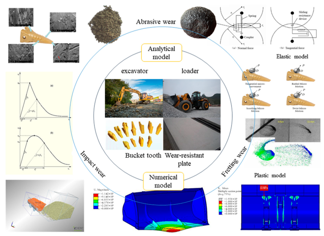
2. Wear Mechanism
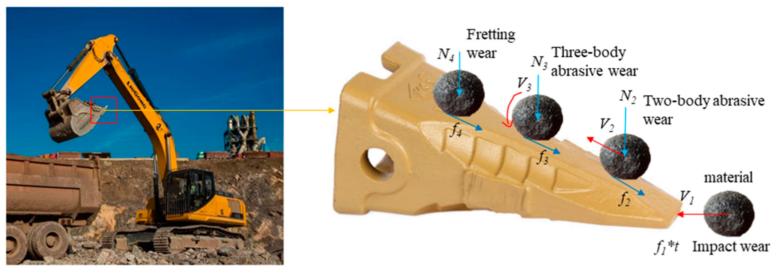
2.1. Wear Mechanism of Bucket Teeth
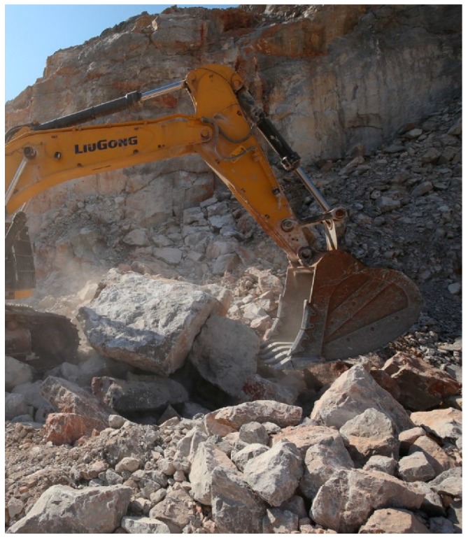
2.2. Impact Wear
2.3. Abrasive Wear
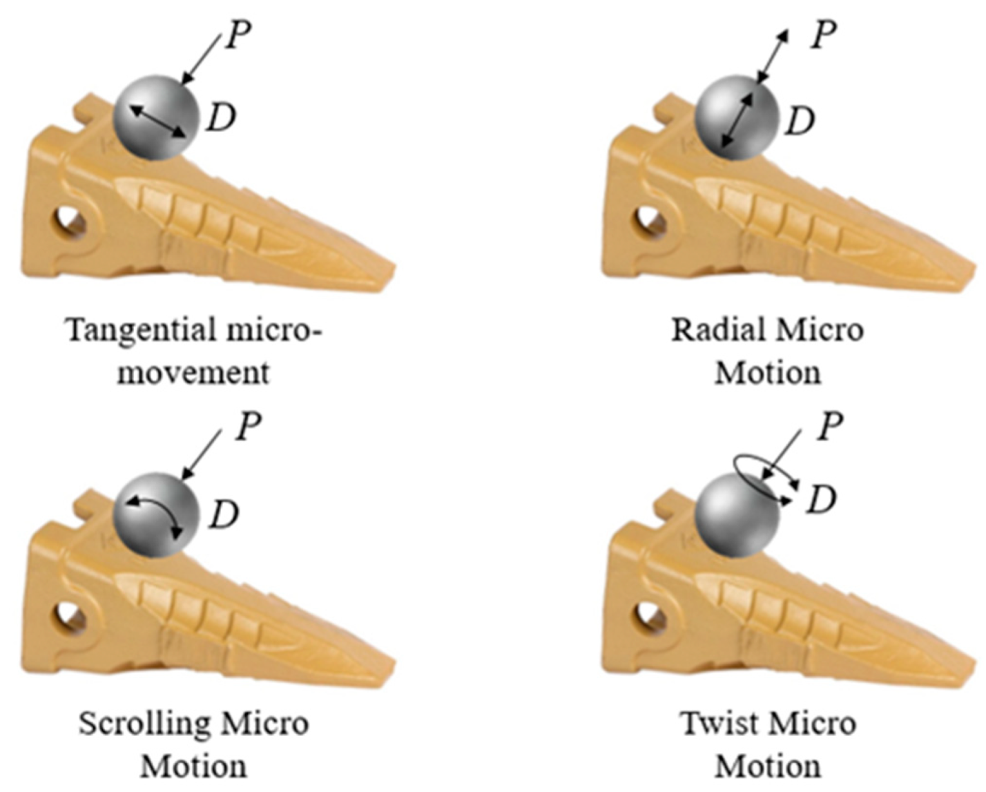
2.4. Fretting Wear
2.5. Wear Morphology
3. Analytical Methods
3.1. Constitutive Model of Tooth Materials
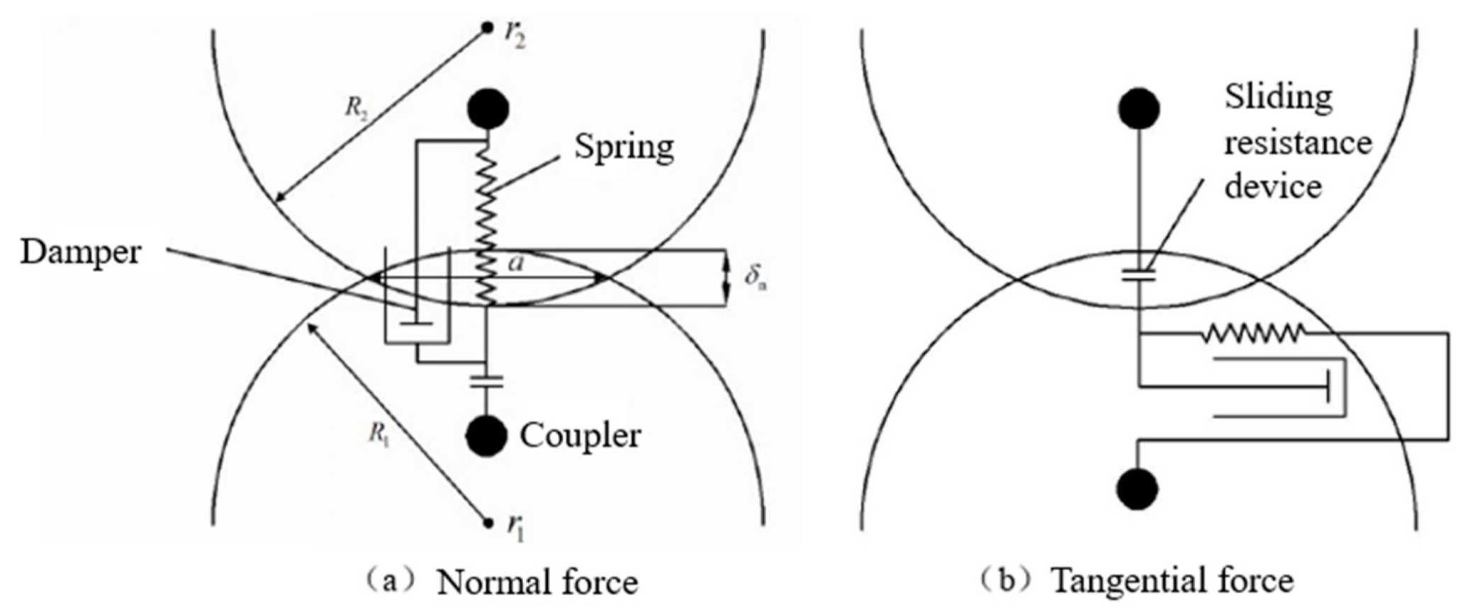
3.2. Friction Model
3.3. Wear Model
4. Numerical Simulation Methods
4.1. Introduction to Numerical Modeling Methods
4.2. Discrete Element Method
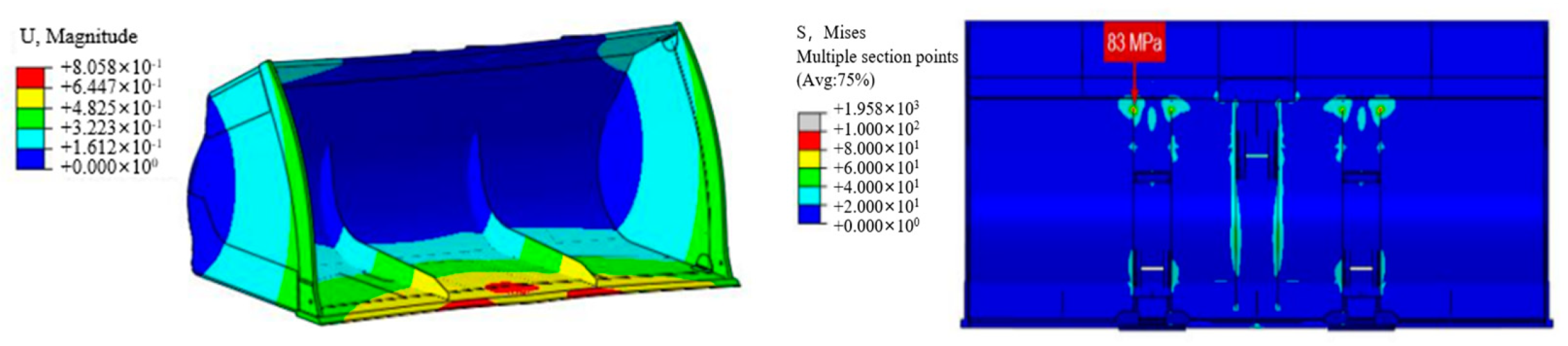
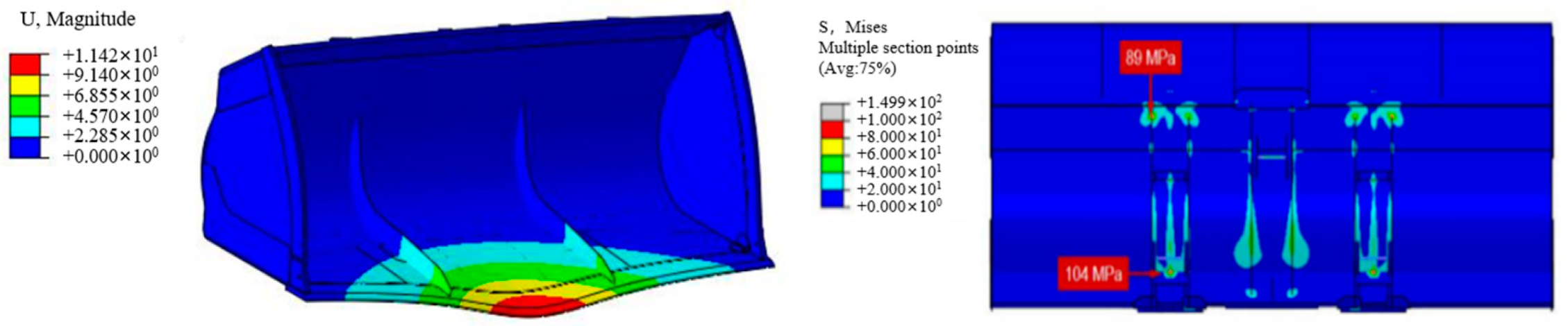
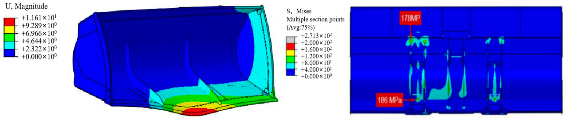
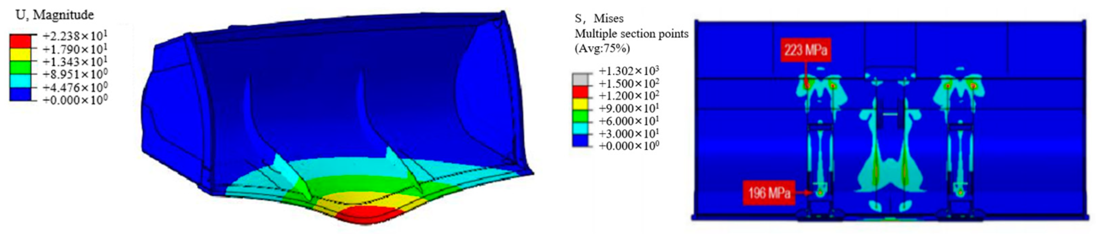
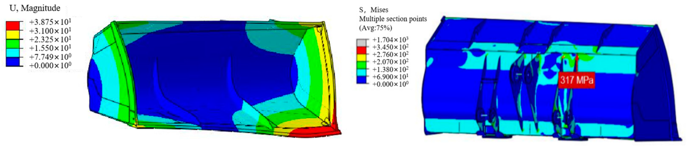
4.3. Finite Element Method
4.4. Smoothed Particle Hydrodynamics Method
5. Conclusions
Author Contributions
Funding
Data Availability Statement
Conflicts of Interest
References
- Chen, H. Research on the Development of China’s Construction Machinery Industry in the New Period. Chin. Mark. 2019, 11, 52–54. (In Chinese) [Google Scholar] [CrossRef]
- Bayer, R.G. Mechanical Wear Prediction and Prevention; Dekker: New York, NY, USA, 1994; pp. 200–291. [Google Scholar]
- Nezami, E.G.; Hashash, Y.M.A.; Zhao, D.; Ghaboussi, J. Simulation of front end loader bucket–soil interaction using discrete element method. Int. J. Numer. Anal. Methods Geomech. 2007, 31, 1147–1162. [Google Scholar] [CrossRef]
- Zhao, Y.P. Research on Heat Treatment and Microstructure and Properties of 30Cr2MnSi Steel for Bucket Teeth of Excavator. Master’s Thesis, Shandong University, Jinan, China, 2019. (In Chinese). [Google Scholar]
- Jiang, F.; Lim, F.; Li, J. Abrasion Course Analysis on Pins of Loader Working Equipment and lmproverment. Lubr. Eng. 2007, 191, 132–135. (In Chinese) [Google Scholar]
- Zhang, T.; Wang, N.; Cheng, X. The comparison research on design methodology of pins. J. Mech. Strength 2015, 37, 461–466. (In Chinese) [Google Scholar] [CrossRef]
- Cristine, H.; Tasevski, A. Design of Bucket Teeth. Master’s Thesis, Mälardalens University, Västerås, Sweden, 2016. [Google Scholar]
- Williams, J.A. Wear and wear particles—some fundamentals. Tribol. Int. 2005, 38, 863–870. [Google Scholar] [CrossRef]
- Chen, X.-D.; Wang, L.-W.; Yang, L.-Y.; Tang, R.; Yu, Y.-Q.; Cai, Z.-B. Investigation on the impact wear behavior of 2.25 Cr–1Mo steel at elevated temperature. Wear 2021, 476, 203740. [Google Scholar] [CrossRef]
- Dhirendra, K.S.; Vijay, K.J. Analysis of surface texture generated by a flexible magnetic abrasive brush. Wear 2005, 259, 1254–1261. [Google Scholar] [CrossRef]
- Zhang, W. Study on the failure Mechanism and Control of Bucket Teeth in Large-scale Mine Excavator. Nonferrous Metall. Equip. 2017, 3, 5–10+31. (In Chinese) [Google Scholar] [CrossRef]
- Rice, S.L.; Nowotny, H.; Wayne, S.F. Characteristics of metallic subsurface zones in sliding and impact wear. Wear 1981, 74, 131–142. [Google Scholar] [CrossRef]
- Engel, P.A.; Lyons, T.H.; Sirico, J.L. Impact wear model for steel specimens. Wear 1973, 23, 185–201. [Google Scholar] [CrossRef]
- Yang, Y. Research on the Microstructure, Mechanical and Impact Abrasion Behavior of Fe-Mn-Al-C Lightweight High Manganese Steel. Master’s Thesis, Nanchang Hangkong University, Nanchang, China, 2021. (In Chinese). [Google Scholar] [CrossRef]
- Zhang, F.; Shao, F.; Zhou, D. Research on Impact Wear Mechanism of High Manganese Steel Mn13Cr2. J. Hunan Univ. (Nat. Sci.) 2014, 41, 6–10. (In Chinese) [Google Scholar]
- Yan, L.; Jiang, F.; Rong, Y. Application of Equal Life Methodology on Design of Pin Group. J. Mech. Eng. 2013, 49, 130–136. (In Chinese) [Google Scholar] [CrossRef]
- Rhoades, L. Abrasive flow machining: A case study. J. Mater. Process. Technol. 1991, 28, 107–116. [Google Scholar] [CrossRef]
- Davies, P.J.; Fletcher, A.J. The assessment of the rheological characteristics of various polyborosiloxane/grit mixtures as utilized in the abrasive flow machining process. Proc. Inst. Mech. Eng. Part C J. Mech. Eng. Sci. 1995, 209, 409–418. [Google Scholar] [CrossRef]
- Wang, A.C.; Weng, S.H. Developing the polymer abrasive gels in AFM processs. J. Mater. Process. Technol. 2007, 192, 486–490. [Google Scholar] [CrossRef]
- Sankar, M.R.; Jain, V.; Ramkumar, J.; Joshi, Y. Rheological characterization of styrene-butadiene based medium and its finishing performance using rotational abrasive flow finishing process. Int. J. Mach. Tools Manuf. 2011, 51, 947–957. [Google Scholar] [CrossRef]
- Singla, S.; Kang, A.S.; Grewal, J.S.; Cheema, G.S. Wear behavior of weld overlays on excavator bucket teeth. Procedia Mater. Sci. 2014, 5, 256–266. [Google Scholar] [CrossRef] [Green Version]
- Tomlinson, G.A.; Thorpe, P.L.; Gough, H.J. An investigation of the fretting corrosion of closely fitting surfaces. Proc. Inst. Mech. Eng. 1939, 141, 223–249. [Google Scholar] [CrossRef]
- Godfrey, D. Investigation of Fretting by Microscopic Observation; Lewis Flight Propulsion Laboratory: Cleveland, Ohio, 1951. [Google Scholar]
- Godet, M. Third-bodies in tribology. Wear 1990, 136, 29–45. [Google Scholar] [CrossRef]
- Zhang, H.; Liu, J.; Zuo, Z. Investigation into the effects of tangential force on fretting fatigue based on XFEM. Tribol. Int. 2016, 99, 23–28. [Google Scholar] [CrossRef]
- Li, L. Development and Experimental Study of a Testing Machine for Fretting Friction Wear. Master’s Thesis, Nanjing University of Aeronautics and Astronautics, Nanjing, China, 2010. (In Chinese). [Google Scholar]
- Straffelini, G.; Molinari, A. Mild sliding wear of Fe–0.2% C, Ti–6% Al–4% V and Al-7072: A comparative study. Tribol. Lett. 2011, 41, 227–238. [Google Scholar] [CrossRef]
- Straffelini, G.; Molinari, A. Dry sliding wear of Ti–6Al–4V alloy as influenced by the counterface and sliding conditions. Wear 1999, 236, 328–338. [Google Scholar] [CrossRef]
- Kong, H.; Ashby, M.F. Wear mechanisms in brittle solids. Acta Metall. Et Mater. 1992, 40, 2907–2920. [Google Scholar] [CrossRef]
- Valtonen, K.; Keltamäki, K.; Kuokkala, V.T. High-stress abrasion of wear resistant steels in the cutting edges of loader buckets. Tribol. Int. 2018, 119, 707–720. [Google Scholar] [CrossRef]
- Yang, L.J. A methodology for the prediction of standard steady-state wear coefficient in an aluminium-based matrix composite reinforced with alumina particles. J. Mater. Process. Technol. 2005, 162, 139–148. [Google Scholar] [CrossRef]
- Hu, Y. Analysis on Wear Failure of Bucket Teeth of Mine Excavators and the Anti-wear Measures. Lubr. Eng. 2006, 5, 165–167. (In Chinese) [Google Scholar]
- Valtonen, K.; Ratia, V.; Ojala, N.; Kuokkala, V.-T. Comparison of laboratory wear test results with the in-service performance of cutting edges of loader buckets. Wear 2017, 388, 93–100. [Google Scholar] [CrossRef]
- Keleş, A.; Yildirim, M. Improvement of mechanical properties by means of titanium alloying to steel teeth used in the excavator. Eng. Sci. Technol. Int. J. 2020, 23, 1208–1213. [Google Scholar] [CrossRef]
- Morito, S.; Tanaka, H.; Konishi, R.; Furuhara, T.; Maki, T. The morphology and crystallography of lath martensite in Fe-C alloys. Acta Mater. 2003, 51, 1789–1799. [Google Scholar] [CrossRef]
- Qiu, C.M.; Wang, Y.F.; Xing, S.M.; Guo, L.J. The Failure Mechanism of Bucket Teeth of Electric Excavator Used in Metal Mine. Adv. Mater. Res. 2012, 580, 185–188. Available online: https://www.scientific.net/AMR.580.185 (accessed on 8 May 2023).
- Coetzee, C.J.; Els, D.N.J. The numerical modelling of excavator bucket filling using DEM. J. Terramech. 2009, 46, 217–227. [Google Scholar] [CrossRef]
- Guo, H.; Liu, Y.; Li, W. The Investigation of Wear Mechanism and Material Selection of Bucket Teeth on Excavator. Mater. Rep. 2014, 28, 99–103. (In Chinese) [Google Scholar]
- Wang, P. Theoretical Studies on Failure Model, Steady State and Stability of Metallic Material Subjected to Plastic Deformation. Ph.D. Thesis, Zhejiang University, Hangzhou, China, 2019. [Google Scholar] [CrossRef]
- Yu, H. Evaluation of fatigue life under multiaxial low-cycle loadings applying the von mises and tresca yield criteria. J. Mech. Strength 2000, 253–255. [Google Scholar] [CrossRef]
- Meng, H.C.; Ludema, K.C. Wear models and predictive equations: Their form and content. Wear 1995, 181, 443–457. [Google Scholar] [CrossRef]
- Chen, L.; Peng, G.; Luo, S. Fatigue Analysis of Bucket Tooth on Basis of Finite-element Method. Therm. Process. Technol. 2015, 44, 49–52. [Google Scholar] [CrossRef]
- Besson, J. Continuum models of ductile fracture: A review. Int. J. Damage Mech. 2010, 19, 3–52. [Google Scholar] [CrossRef] [Green Version]
- Bošnjak, S.M.; Arsić, M.A.; Gnjatović, N.B.; Milenović, I.L.; Arsić, D.M. Failure of the bucket wheel excavator buckets. Eng. Fail. Anal. 2018, 84, 247–261. [Google Scholar] [CrossRef]
- Durst, W.; Vogt, W. Bucket wheel excavator; Trans Tech Publications Ltd.: Zürich, Switzerland, 1988. [Google Scholar]
- Das, M.K.; Sarkar, S.; Choudhary, B.S. Structure analysis of a dragline tooth and its wear prediction. Trans. Can. Soc. Mech. Eng. 2019, 43, 526–534. [Google Scholar] [CrossRef]
- Li, K.; Wen, R. Research on friction model in mechanical system. J. Green Sci. Technol. 2015, 12, 275–276. (In Chinese) [Google Scholar] [CrossRef]
- Kogut, L.; Etsion, I. A static friction model for elastic-plastic contacting rough surfaces. J. Trib. 2004, 126, 34–40. [Google Scholar] [CrossRef] [Green Version]
- Özel, T. The influence of friction models on finite element simulations of machining. Int. J. Mach. Tools Manuf. 2006, 46, 518–530. [Google Scholar] [CrossRef]
- Huang, Z. Finite Element Analysis of Pile Jacked in Sand Based on State-Dependent Mohr-Coulomb Constitutive Model. Master’s Thesis, Zhejiang University, Hangzhou, China, 2022. (In Chinese). [Google Scholar] [CrossRef]
- Lin, Z. Application of Upper Limit Method in Plastic Processing; China Railway Press: Beijing, China, 1991; pp. 25–29. [Google Scholar]
- Im, Y.T.; Kang, S.H.; Cheon, J.S. Finite element investigation of friction condition in a backward extrusion of aluminum alloy. J. Manuf. Sci. Eng. 2003, 125, 378–383. [Google Scholar] [CrossRef]
- Zöllner, F. Leonardo da Vinci, 1452–1519; Taschen: Köln, Germany, 2000. [Google Scholar]
- Ebnoether, F.; Mohr, D. Predicting ductile fracture of low carbon steel sheets: Stress-based versus mixed stress/strain-based Mohr–Coulomb model. Int. J. Solids Struct. 2013, 50, 1055–1066. [Google Scholar] [CrossRef] [Green Version]
- Stembalski, M.; Preś, P.; Skoczyński, W. Determination of the friction coefficient as a function of sliding speed and normal pressure for steel C45 and steel 40HM. Arch. Civ. Mech. Eng. 2013, 13, 444–448. [Google Scholar] [CrossRef]
- Figueiredo, L.; Ramalho, A.; Oliveira, M.; Menezes, L.F. Experimental study of friction in sheet metal forming. Wear 2011, 271, 1651–1657. [Google Scholar] [CrossRef]
- Archard, J.F. Contact and rubbing of flat surfaces. J. Appl. Phys. 1953, 24, 981–988. [Google Scholar] [CrossRef]
- Zhang, Y. Wear Analysis and Structure Improvement on Bucket Tooth of WK-75 Mining Excavator. Master’s Thesis, Taiyuan University of Technology, Taiyuan, China, 2016. (In Chinese). [Google Scholar]
- Cleary, P.W. Large scale industrial DEM modelling. Eng. Comput. 2004, 21, 169–204. [Google Scholar] [CrossRef]
- Ouyang, H. Wear prediction of friction material and brake squeal using the finite element method. Wear 2008, 264, 1069–1076. [Google Scholar] [CrossRef] [Green Version]
- Liu, M.B.; Liu, G.R. Smoothed particle hydrodynamics (SPH): An overview and recent developments. Arch. Comput. Methods Eng. 2010, 17, 25–76. [Google Scholar] [CrossRef] [Green Version]
- Takahashi, H. Simulation of the resistive forces acting on the bucket of wheel loader by use of DEM. In Proceedings of the 5th Asia-Pacific Conference, Seoul, Republic of Korea, 1998; pp. 37–44. Available online: http://www2.kankyo.tohoku.ac.jp/htaka/Japanese/paper/htaka/pdf/2.pdf (accessed on 8 May 2023).
- Coetzee, C.J.; EIs, D. Modelling excavator bucket filling with DEM. Fifth World Congr. Comput. Mech. 2002, 7, 7–12. [Google Scholar]
- Yu, X.; Chen, Y.; Xie, G. The simulation analysis of different tooth numbers of loader bucket based on EDEM. IOP Conf. Ser. Mater. Sci. Eng. 2018, 423, 012055. [Google Scholar] [CrossRef]
- Demircioğlu, P.; Böğrekci, I.; Hamisu, S. Analysis of interactive effects of bulk material on excavator bucket. Uluborlu Mesleki Bilimler Dergisi 2021, 4, 1–12. [Google Scholar]
- Mughal, K.H.; Bugvi, S.A.; Qureshi, M.A.M.; Khan, M.A.; Hayat, K. Numerical Evaluation of Contemporary Excavator Bucket Designs using Finite Element Analysis. J. Kejuruter. 2021, 33, 579–591. [Google Scholar] [CrossRef]
- Wriggers, P. Finite element methods for contact problems with friction. Tfibology Int. 1996, 29, 651–658. [Google Scholar] [CrossRef]
- Hao, D. Fatigue life prediction and optimization design of sign of loader bucket based on load spectrum. Qingdao Univ. Technol. 2021. [Google Scholar] [CrossRef]
- Jiang, F.; Li, J.; Li, F. Offset Loading Coefficient Method on the Intensity Analysis of Lift-arms. China Mech. Eng. 2008, 243, 272–276. (In Chinese) [Google Scholar]
- Johnson, G.R.; Stryk, R.A.; Beissel, S.R. SPH for high velocity impact computations. Comput. Methods Appl. Mech. Eng. 1996, 139, 347–373. [Google Scholar] [CrossRef]
- Zhong, X. Research on Smooth Excavating Planning of Automatic Excavator. Master’s Thesis, Huaqiao University, Quanzhou, China, 2018. (In Chinese). [Google Scholar]
- Zhang, Y.Y.; He, F.; Li, C.L.; Gao, Y.; Gao, P. Simulation Analysis on Strength of Bucket Tooth with Various Soil. Adv. Mater. Res. 2013, 619, 62–65. Available online: https://www.scientific.net/AMR.619.62 (accessed on 8 May 2023).
- Huang, P.; Wang, J.; Wang, L.; Qian, J. Dimensional synthesis for 3-PRS mechanism based on identifiability performance. Chin. J. Mech. Eng. 2012, 25, 234–240. [Google Scholar] [CrossRef]
- Ma, A.; Liao, Q.; Tian, B.; Huang, H.; Shu, C.; Zhou, S.; Lin, X. Numerical Simulation of Soil Cutting by Spiral Cutter on the Basisi of ANSYS/LS-DYNA. J. Huazhong Agric. Univ. 2009, 28, 248–252. [Google Scholar]


| Algorithm | Applicable Object | Simulation Research of Bucket Teeth |
|---|---|---|
| DEM | Numerical simulation method for solving discontinuous media problems | The simulation of the shovel digging process can obtain the motion characteristics of the bucket and determine the maximum wear position |
| FEM | Numerical techniques for solving approximate solutions to boundary value problems in partial differential equations | The force of each part of the bucket teeth is simulated to determine the maximum load position |
| SPH | Fluid or solid | Coupled with finite element to study the material movement and study the wear of bucket teeth in natural conditions |
| Wear Mechanisms | Working Conditions and Locations | Features | Modeling Method |
|---|---|---|---|
| Impact wear | In the case of ore excavation, the tip of the bucket tooth often occurs | With high stress, easy to destroy the surface of the material and other characteristics, more obvious wear | Failure models, wear models, finite elements, etc. |
| Two-body abrasive wear | In the excavator loader shoveling material, often occurs in the bucket tooth surface | Subject to certain pressure, the wear is a continuous sliding wear process, the surface of the bucket tooth is scratched, and plastic deformation occurs | Plasticity model, discrete element, finite element, SPH, etc. |
| Three-body abrasive wear | Often occurs on the surface of the bucket teeth during bucket discharge | Almost no pressure, wear is a continuous rolling wear process, scratches on the surface of the bucket teeth, plastic deformation | Plasticity model, discrete element, finite element, SPH, etc. |
| Fretting wear | Occurs throughout the bucket tooth operation and is located at the upper end of the bucket tooth | Tiny, continuous, can lead to crack propagation, highly influenced by the environment | Failure model, plasticity model, friction model |
Disclaimer/Publisher’s Note: The statements, opinions and data contained in all publications are solely those of the individual author(s) and contributor(s) and not of MDPI and/or the editor(s). MDPI and/or the editor(s) disclaim responsibility for any injury to people or property resulting from any ideas, methods, instructions or products referred to in the content. |
© 2023 by the authors. Licensee MDPI, Basel, Switzerland. This article is an open access article distributed under the terms and conditions of the Creative Commons Attribution (CC BY) license (https://creativecommons.org/licenses/by/4.0/).
Share and Cite
Dong, Z.; Jiang, F.; Tan, Y.; Wang, F.; Ma, R.; Liu, J. Review of the Modeling Methods of Bucket Tooth Wear for Construction Machinery. Lubricants 2023, 11, 253. https://doi.org/10.3390/lubricants11060253
Dong Z, Jiang F, Tan Y, Wang F, Ma R, Liu J. Review of the Modeling Methods of Bucket Tooth Wear for Construction Machinery. Lubricants. 2023; 11(6):253. https://doi.org/10.3390/lubricants11060253
Chicago/Turabian StyleDong, Zhengxing, Feng Jiang, Yuanqiang Tan, Fuzeng Wang, Rong Ma, and Jiawen Liu. 2023. "Review of the Modeling Methods of Bucket Tooth Wear for Construction Machinery" Lubricants 11, no. 6: 253. https://doi.org/10.3390/lubricants11060253