Article

Numerical Calculation Method of Multi-Lip Seal Wear under Mixed Thermal Elastohydrodynamic Lubrication

1
School of Mechanical and Electrical Engineering, Xi’an University of Architecture and Technology, Xi’an 710055, China
2
School of Science, Xi’an University of Architecture and Technology, Xi’an 710055, China
3
Engineering Comprehensive Training Center, Xi’an University of Architecture and Technology, Xi’an 710055, China
*
Author to whom correspondence should be addressed.
Lubricants 2023, 11(6), 248; https://doi.org/10.3390/lubricants11060248
Submission received: 7 April 2023 / Revised: 26 May 2023 / Accepted: 1 June 2023 / Published: 6 June 2023
(This article belongs to the Special Issue Modelling in Tribology and Biotribology)

Abstract

:
The multi-lip combined seal has the advantages of multi-lip coupling, large supporting force, and can withstand high-pressure shocks. It is an irreplaceable structure for single-lip seals. However, most of the seal wear analysis focuses on the simulation method of the single-lip seal under the influence of macro factors, and very little involves the wear characteristics of multi-lip seals. In this paper, a micro numerical method is established, which combines the elastohydrodynamic lubrication theory with the modified Archard equation. The performance of a multi-lip combined seal under different working conditions is analyzed through simulation, including macro and micro factors. It is found that some of the characteristics of single-lip seals are also reflected in multi-lip seals, and there is a critical speed that makes the sealing behavior of each seal lip different.

1. Introduction

As an important component of hydraulic cylinders, the piston seal plays a decisive role in ensuring energy conversion and preventing internal leakage of the hydraulic actuator. Due to the interference fit between the cylinder inner wall and the seal, the surface of the seal and the cylinder wall are formed with small asperities after processing and molding. After many reciprocating actions of the piston rod, the friction between the cylinder wall and the piston seal makes the cylinder wall smoother. At the same time, the roughness height of the seal contact surface also migrates and changes, which leads to the wear loss of seal material and changes the geometric contour of the seal lip, ultimately directly affecting the sealing system properties [1,2]. Research shows that the asperity formed on the surface of a worn seal is more conducive to the generation of a fluid film, and it can significantly reduce seal wear [3]; the most typical kind of seal failure is wear, so it is significant to accurately reveal and predict seal wear characteristics [4].
In order to understand the seal wear behavior, some experimental methods have been proposed. Ridgway et al. [5] explored the wear characteristics of the seal ring in the slurry-free environment through experiments and found that the non-uniform packing compression is not the only factor affecting the life and reliability of the gland seal. Yang et al. [6] evaluated the friction behavior of seals containing different polytetrafluoroethylene (PTFE) contents under dry friction conditions, and the results showed that the sliding speed had significant effects on the frictional behavior of the filled PTFE seal. Lee et al. [7] proposed an experimental method for the accelerated wear of fluororubber (FKM) seals and discovered that the wear rate of FKM could be raised by 58-times when 0~1 mm alumina particles were mixed with lubricant, but its wear performance was similar to normal working conditions. Wang et al. [8] observed, through experiments, that the wear coefficient of an amorphous carbon coating on the seal surface is low in a low-temperature environment. Liu et al. [9] tested the impact of various pressures on the wear rate of PTFE piston seals in automobile fuel distributors through experiments. The results showed that the seal wore away more quickly at higher pressures. Gao et al. [10] used a self-developed tribology tester to study the wear performance of different coating seals. It is found that the maximum possible temperature and temperature rise rate of the friction surface are two key factors that affect the blade wear performance and the coating wear resistance. Rahmani et al. [11,12] compared the leakage rate of radial lip seals and shafts with different surface topography and found that shafts with negative skewness surface topography caused less leakage. This research result can provide technical guidance for basic component processing and structural optimization.
Although the experimental research of friction and wear can actually reflect the tribological characteristics of the seal, the experimental operation requires both manpower and material resources. Therefore, it is required to study the friction characteristics of the seal through the numerical simulation method. Based on the short-term wear data, Yang et al. [13] predicted the long-term wear degree of the hydraulic cylinder piston seal through a numerical model. Békési et al. [14] introduced a technique to simulate the effect of seal wear by using the birth–death element technology of the finite element method (FEM) for reciprocating seals. However, the model has a large error in calculating the regions of high contact pressure. Frölich et al. [15] established a macro FEM simulation model that simultaneously considers the interactions of temperature, friction and wear, which can better simulate the wear state of the rotating shaft seal. Li et al. [16] established a thermal-structural coupling simulation method for seal wear based on FEM mesh reconstruction technology and compared the wear of the rotating-shaft O-ring and the rectangular ring; this method is helpful to understand the temperature distribution of the seal during wear. However, the above methods mainly focus on the research on the friction characteristics of the macro deformation caused by the external force extrusion of the seal, and they ignore the effect of the micro factors in the lubrication interface on the seal wear. As is well known, seal macro deformation can cause contact friction, and friction heat generation reduces the viscosity of the fluid, which leads to poor lubrication and increased wear, and seal wear, in turn, exacerbates fluid leakage [17]. Therefore, the macro deformation mechanics of the seal are strongly coupled with the micro hydrodynamics of the fluid film [18]. Zhang et al. [19] simplified the seal wear process by directly modifying the geometric profile of the seal and finally analyzed the lubrication characteristics of different profile seals. However, this method ignored the influence of lubricating fluid on the wear characteristics and could not accurately reflect the dynamic coupling process of lubrication characteristics and seal wear. Therefore, when analyzing lubrication on seal wear, Liu et al. [20] and Ran et al. [21] combined lubrication and wear to establish multi-scale numerical wear simulation models for rotary seals and reciprocating seals, respectively. This numerical model is helpful for researchers to understand the wear characteristics of seals from the micro perspective.
However, the above studies are for simple single-lip seals, which have only one seal lip in contact with the cylinder wall, making it easier to obtain the calculation results during the analysis process. With the development trend of high speed and high pressure in the hydraulic industry, the single-lip seal cannot easily ensure the requirements of a transmission mechanism for sealing performance and running quality, and more and more multi-lip seals are widely used. According to relevant studies, due to the strong coupling relationship formed by the fluid pressure between the multi-lip seal lips, the lubrication characteristics of multi-lip seals and single-lip seals in service are very different [22].
In view of the above problems, this paper takes the double-acting seal (DAS) multi-lip combined seal as the research object. Based on the multi-scale numerical wear simulation model [21], a numerical simulation method for reciprocating multi-lip seal wear considering micro factors is proposed. Under the theory of mixed lubrication, the mixed thermoelastohydrodynamic lubrication model (M-TEHL) of a multi-lip seal is established by taking the principle of flow conservation as a convergence criterion to solve the micro lubrication characteristics of the seals. The average asperity contact pressure is obtained by discretizing and statistically calculating the micro asperity contact pressure of the seal surface obtained from the lubrication model, which is introduced to modify the Archard wear equation to calculate the seal wear thickness. The wear condition of the DAS multi-lip combined seal under various working conditions is studied.

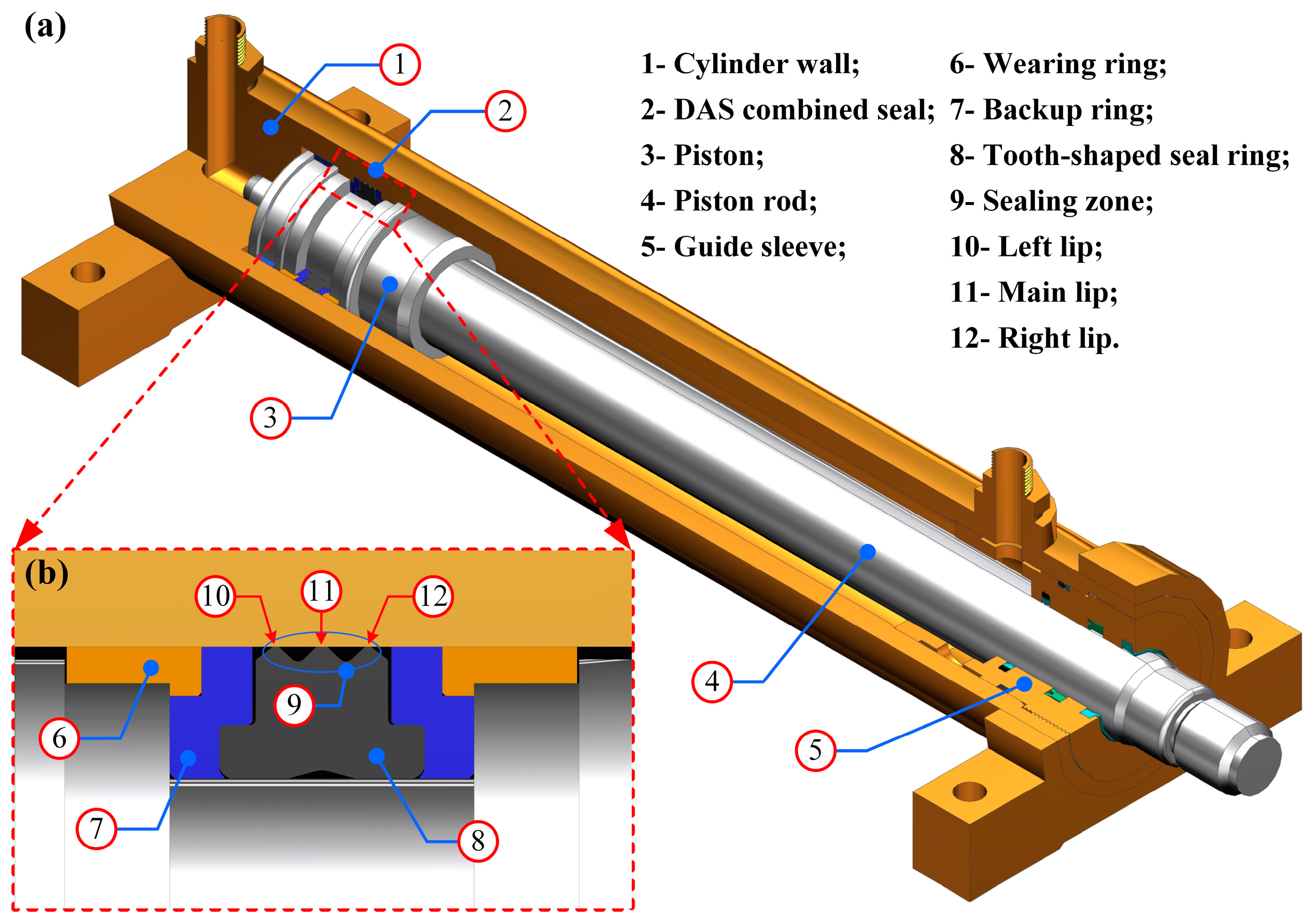
2. Geometric Structure

A hydraulic cylinder piston application schematic for a typical DAS multi-lip combined seal is presented in Figure 1. The primary assembly structure of the hydraulic cylinder is depicted in Figure 1a. When the cylinder is actuated, the piston drives the piston rod to reciprocate linearly along the guide sleeve. The DAS-combined seal is primarily used to seal the clearance gap formed by the piston and the cylinder wall to prevent internal leakage of hydraulic oil. Therefore, the piston sealing performance directly affects whether the hydraulic cylinder can work normally. The whole seal structure of the DAS-combined seal is symmetrically distributed and consists of five parts: one nitrile rubber (NBR) tooth-shaped seal ring, two thermoplastic polyester elastomer (TPE) backing rings and two polyformaldehyde (POM) L-shaped wearing rings, as illustrated in Figure 1b. The tooth-shaped seal ring consists of three seal lips: the higher seal lip in the middle is the main lip, and the lower seal lips on both sides are the left lip and the right lip. In the reciprocating movement, the DAS-combined seal is installed in the groove to form three sealing zones. In addition, the left lip and the right lip form two pressure zones with the main lip, which are called the first and second inter-lip zones, respectively. Hydraulic oil penetrates the clearance gap of the seal to form a lubricating oil film, which reduces movement damping and seal wear.

3. Theoretical Analysis

In order to solve the problem more efficiently and quickly, the following basic assumptions are proposed to model the multi-lip reciprocating sealing system:
(1) In steady-state conditions, the viscoelastic effect of the seal and the inertia effect of fluid are ignored;
(2) The fluid film thickness is much thinner than the size of the cylinder and the seal element, and the influence of fluid film curvature is ignored;
(3) The fluid in the sealing zone is in a laminar flow state, and there is no relative motion on the boundary;
(4) The macro deformation characteristics of the seal are unaffected by the fluid oil film thickness, and the sealing system is a two-dimensional axisymmetric model;
(5) The inner surface of the cylinder wall is smooth, while the asperity on the seal surface obeys Gaussian distribution.

3.1. Hydrodynamics

During the reciprocating movement, the action mechanism of the fluid film formed in the sealing zone is expressed by the dimensionless Reynolds equation that comprehensively considers both the cavitation effect and surface roughness [23], which is
d d x ^ [ ϕ x x H 3 e α ^ F Φ d ( F Φ ) d x ^ ] = 6 U d d x ^ { [ 1 + ( 1 F ) Φ ] ( H T + ϕ s c x ) }
where x ^ is the axial coordinate, H is the film thickness, HT is the average truncated film thickness, U is the piston rod speed, α ^ is the pressure–viscosity coefficient, F is the cavitation index, Φ is the fluid pressure or the density function and ϕxx and ϕs.c.x are the flow factor [24].
Due to the special structure of the DAS-combined seal, there is a strong coupling characteristic between the three lips under the action of sealed pressure, and the boundary conditions are
{ Φ ( x ^ l = 0 ) = P s ,   Φ ( x ^ l = 1 ) = P i 1   for   left   lip Φ ( x ^ m = 0 ) = P i 1 ,   Φ ( x ^ m = 1 ) = P i 2   for   main   lip Φ ( x ^ r = 0 ) = P i 2 ,   Φ ( x ^ r = 1 ) = P l   for   right   lip
where Ps is the sealed pressure in the high-pressure fluid side, Pi1 and Pi2 are the pressure in the first and second inter-lip zone and Pl is the fluid pressure in the low-pressure fluid side.
The dimensionless fluid viscous friction is
τ ^ f = σ ^ ξ e α ^ F Φ U H ( ϕ f ϕ f s ) ϕ f p σ ^ ξ H 2 d ( F Φ ) d x ^
where ϕf, ϕfs and ϕfp are flow factors [25].
For the integral of Equation (1), the dimensionless fluid flow rate in the sealing zone can be calculated as
q ^ = ϕ x x H 3 e α ^ F ϕ d ( F Φ ) d x ^ + 6 U { [ 1 + ( 1 F ) Φ ] ( H T + ϕ s c x ) }

3.2. Contact Mechanics

The asperity contact needs to be constructed since it is crucial for load distribution in mixed lubrication situations. The asperity contact pressure in the sealing zone is calculated via the Greenwood–Williamson (G-W) model [26] as follows (See Appendix A)
P c = 4 3 1 ( 1 v s 2 ) σ 3 / 2 R 1 / 2 η 1 2 π H ( z H ) 3 / 2 e z 2 / 2 d z
where σ is the seal surface root mean square (RMS) roughness, η is the asperity density and R is the asperity radius.
The dimensionless Coulomb friction of the asperity in the sealing zone is
τ ^ c = f c P c ( U | U | )
where fc is the friction coefficient.

3.3. Deformation Mechanics

The deformation coefficient method is used to determine the micro deformation. From the theory of small deformation, the slight deformation at each position of the seal is linearly positively correlated with the applied load [27], which is
H i = H s + k = 1 n ( K ) i k ( P f + P c P s c ) k
where Hs is the initial film thickness and K and Psc are the deformation coefficient matrix and static contact pressure obtained using ANSYS software, respectively.

3.4. Thermal Mechanics

Assuming that the ambient temperature is unaffected and that the thermal conductivity of the cylinder is significantly greater than that of the seal, all heat produced by the friction among the solid and the fluid is completely transferred to the cylinder wall. Therefore, the thermal analysis model of the sealing zone is [28]
T T 0 = { 1.07 Q L 2 k c [ ρ c c c | u | L k c ] 1 2   , for   ρ c c c | u | L k c > 0.68 0.64 Q L 2 k c ln [ 5.0 k c ρ c c c | u | L ]   , for   ρ c c c | u | L k c < 0.68
where T is the fluid film temperature, T0 is the ambient temperature, kc is the thermal conductivity of the cylinder wall, ρc is the density of the cylinder wall, cc is the specific heat capacity of the cylinder wall, L is the contact length of the seal lip and Q is the heat production rate of the cylinder wall.

3.5. Coupling Mechanics

During the heat production of solid and fluid friction, the fluid viscosity is a result of combined effects from both the fluid temperature and fluid pressure. The Roelands viscosity–pressure–temperature empirical equation is applied to calculate the fluid film viscosity [29], that is
{ μ = μ 0 exp { ( ln μ 0 + 9.67 ) × [ ( 1 + 5.1 × 10 9 p f ) ϑ × ( T 138 T 0 138 ) ϖ 1 ] } ϑ = α / [ 5.1 × 10 9 ( ln μ 0 + 9.67 ) ] ϖ = β ( T 0 138 ) / ( ln μ 0 + 9.67 )
where μ0 is the corresponding viscosity under the ambient pressure p0 and temperature T0, α is the Barus viscosity–pressure coefficient and β is the Reynolds viscosity–temperature coefficient.

3.6. Wear Mechanics

Archard theory is the most commonly used calculation model for material wear [30], so the wear volume of the seal over a period of time during the reciprocating relative movement is
Δ V w = K n H B F n Δ L
where Kn is the dimensionless wear coefficient, ∆Vw is the seal wear volume, HB is the seal material hardness, Fn is the normal force and ∆L is the relative sliding distance.
We defined kn = Kn/HB as the seal material wear coefficient, so Equation (10) can be transformed into
Δ V w = k n F n Δ L
when both sides of Equation (11) are divided by the wear area S, the seal wear depth is
Δ h w = k n p n Δ L
where ∆hw is wear depth and pn is normal contact pressure.
In a mixed lubrication state, the normal contact pressure pn of the cylinder wall to the seal equals the static contact pressure psc of the seal against the cylinder wall, and psc consists of film fluid pressure pf and asperity contact pressure pc, that is, psc = pf + pc.
Assuming that there are no impurities in the fluid medium, the impact of film fluid pressure on seal wear is almost zero. In this case, only asperity contact will lead to seal wear, so Equation (12) can be rewritten as
Δ h w = k n p c Δ L
where kn is the wear coefficient.
When the hydraulic cylinder piston moves, the asperity contact pressure will be changed under the action of elastohydrodynamics. Therefore, when analyzing the influence of lubrication characteristics on the degree of seal wear, the statistical method is used to discrete the single stroke length Lstroke into n parts to calculate the average asperity contact pressure p ¯ c , and then the Archard equation is modified. Finally, the modified Archard equation can be written as
Δ h w = k n p ¯ c L s t r o k e
where
p ¯ c = 1 n i = 1 n ( p c ) i
The total wear volume is
Δ V = π D c 0 L x Δ h w d x
where Dc is the inner diameter of the cylinder wall.
In all cases, wear is a function of time. Therefore, the wear rate is used to analyze seal wear characteristics [31]. The wear time rate (WTR) δt is used to describe the wear volume of a unit of time, and the wear distance rate (WDR) δL is used to describe the wear volume of the unit distance, which are
{ δ t = Δ V Δ t δ L = Δ V Δ L

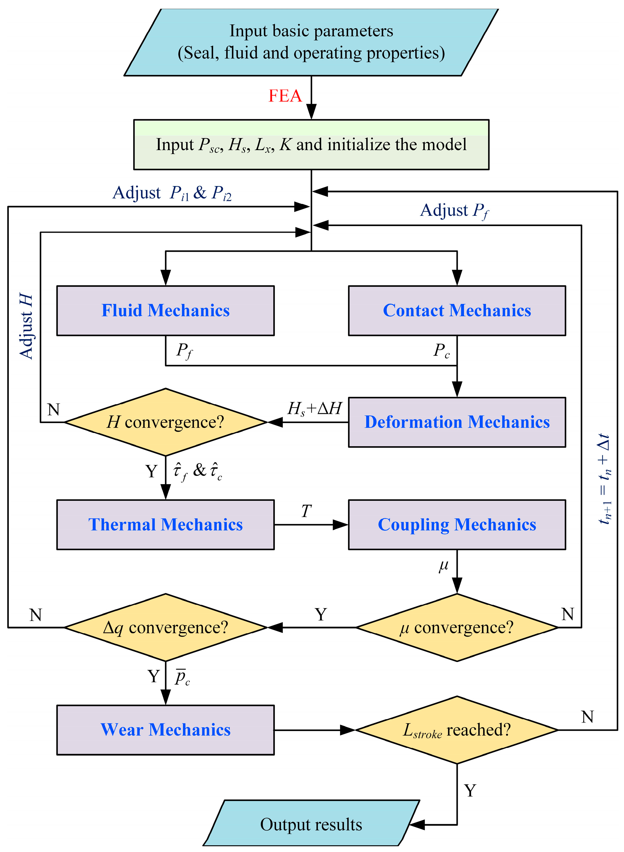
3.7. Numerical Calculation Procedure

From the above analysis, it is clear that the sealing zone exhibits strong thermal–fluid–solid multi-field interaction properties. Therefore, the lubrication properties in MATLAB software are solved through the iterative technique. Finally, the influence of seal wear under mixed thermal elastohydrodynamic lubrication (M-TEHL) conditions is analyzed by modifying the Archard wear equation. Figure 2 shows the numerical algorithm process of the seal wear and the following main steps:
  • In ANSYS software, the finite element analysis (FEA) of seal static solid mechanics is performed based on the characteristics of the seal, fluid and operating conditions.
  • The static contact pressure Psc, Lx, K obtained via FEA and the static initial film thickness Hs calculated by Psc are input into the MATLAB program and initialized.
  • The film fluid pressure Pf and the asperity contact pressure Pc are calculated using the fluid mechanics model and the contact mechanics model, respectively. Then, compare the sum of Pf and Pc with Psc to obtain the pressure difference under dynamic conditions; the pressure difference is applied to calculate the new film thickness.
  • If the film thickness converges, the film temperature can be determined with the thermal mechanics model, which can also determine the fluid viscosity at this temperature convergence via the coupling mechanics model.
  • If the fluid viscosity converges, compare whether the fluid flow rate of the three seal lips is equal. If not equal, the pressure in the first and second inter-lip zone is adjusted until the fluid flow rate is balanced.
  • If the flow rate is equal, judge whether the stroke is reached. If not, carry on simulating the subsequent time step. The wear mechanics model is used to output the results once all the time steps have been performed.

4. Results and Discussion

To investigate the impact of various working conditions on seal wear in the M-TEHL state, the basic parameters are listed in Table 1.

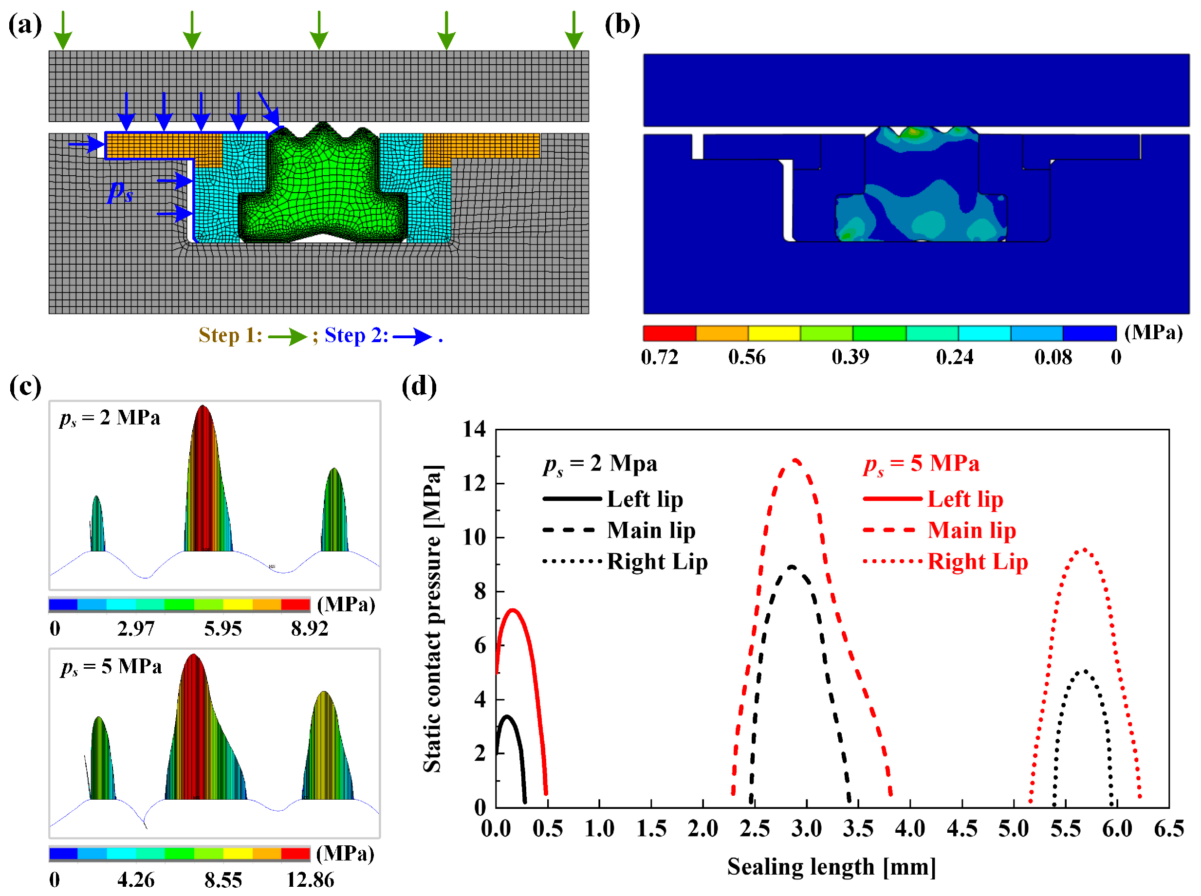
4.1. Static Sealing Performance

As mentioned above, the DAS multi-lip combined seal has axisymmetric characteristics in terms of structure and use. Therefore, the solid mechanics of the seal are investigated using the two-dimensional axisymmetric model in the finite element tool ANSYS, as shown in Figure 3. The two steps of the FEA for the DAS-combined seal are shown in Figure 3a: step 1 (green arrow) is to move the cylinder wall downward to simulate the interference assembly of the seal; step 2 (blue arrow) is to apply a uniform load on one side of the seal to simulate the axial compression of fluid sealed pressure. Figure 3b displays the equivalent von Mises stress that results from the seal being squeezed and deformed under sealed pressure. It can be seen that the maximum von Mises stress value is distributed in the contact zone between the cylinder wall and the main lip, which indicates that the position is prone to local wear and other risks during service. As demonstrated in Figure 3c,d, the static contact pressure and contact length of the seal grow steadily greater as the sealed pressure increases. The maximum static contact pressure shifts toward the fluid side as sealed pressure rises, presenting a strong asymmetric shape. At the same time, it is noticeable that the maximum static contact pressure exceeds the sealed pressure ps, indicating that the contact zone can seal the high-pressure fluid and ensure good sealing performance.

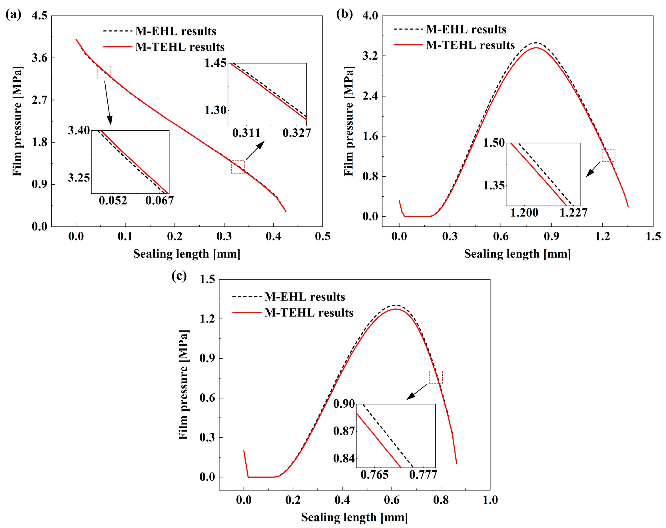
4.2. Model Validation

To verify the validity of the above numerical method, the M-TEHL model is compared with the isothermal mixed elastohydrodynamic lubrication (M-EHL) model under the same operating conditions. Figure 4 shows the film fluid pressure distribution of the DAS multi-lip combined seal calculated using the M-TEHL model and M-EHL model. The sealed pressure, seal surface roughness and piston rod speed are 4 MPa, 0.6 μm and 0.5 m/s, and the fluid viscosity adopts the L-HM 46 oil viscosity defined by the ISO3448-1992 standard. In Figure 4a–c, the calculation results of the M-TEHL model and M-EHL model are in good agreement on the whole. The difference between the calculation results of the two models is mainly due to the influence of temperature variation on fluid performance of the M-TEHL model. During the piston movement, a slight temperature increase is caused through the friction between the seal and the fluid, which reduces the fluid viscosity, which finally causes the film fluid pressure to be lower than the isothermal M-EHL model.

4.3. Dynamic Sealing Performance

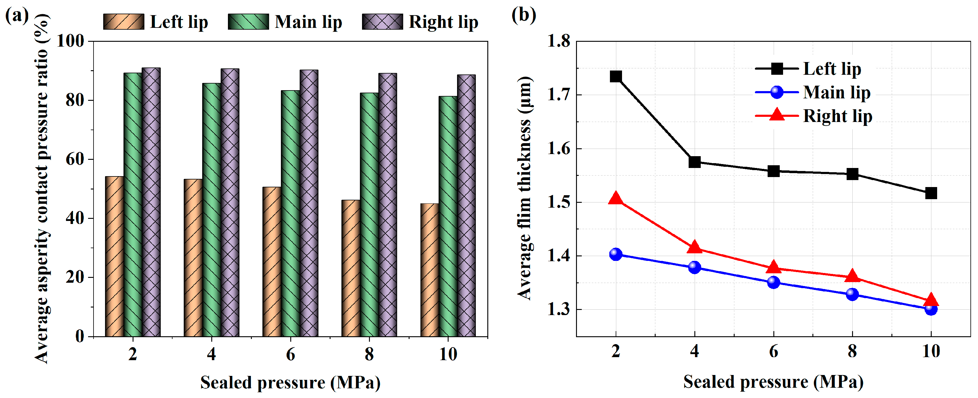
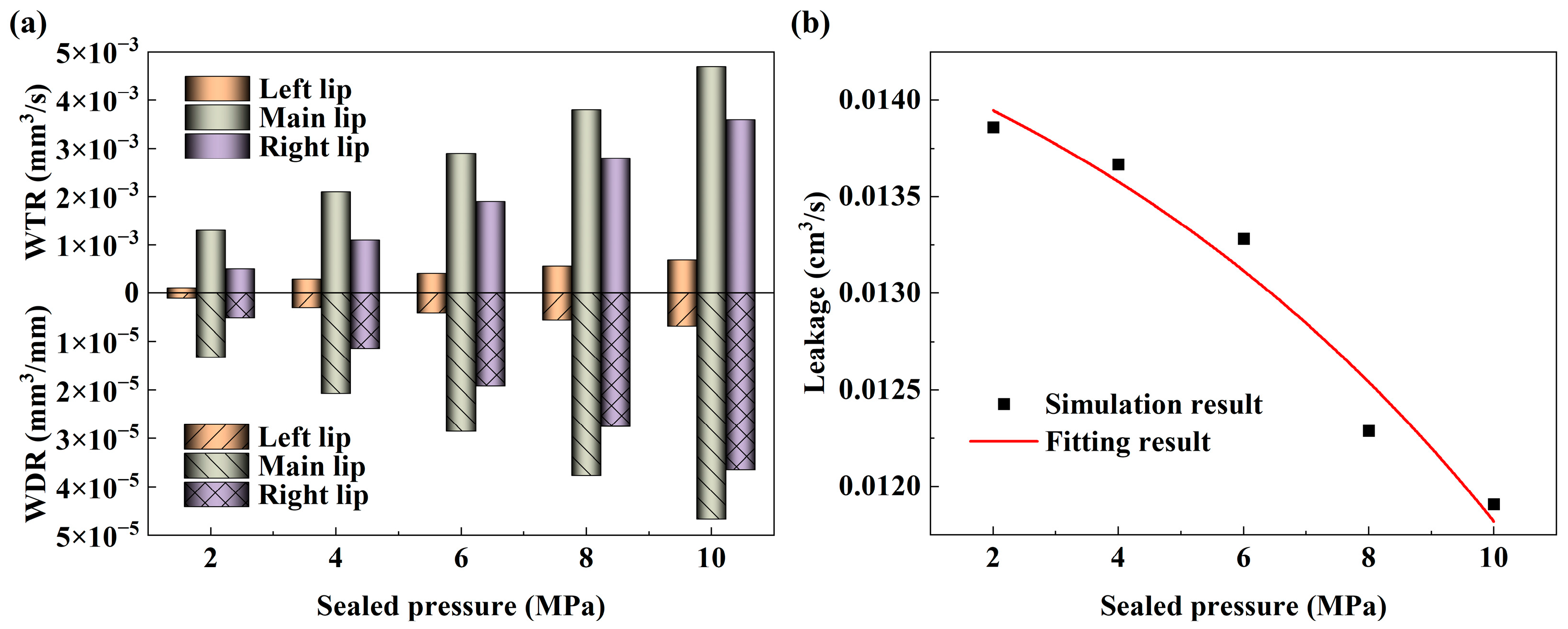
4.3.1. Effect of Sealed Pressure

Figure 5 depicts the influence in different sealed pressures on seal lubrication characteristics. Figure 5a exhibits how the average asperity contact pressure ratio of the three seal lips gradually decreases as sealed pressure increases. From Figure 3, as the sealed pressure rises, the static contact pressure and contact length also rise in a direct correlation, while the film pressure of the three lips will rise correspondingly along the high-pressure fluid side and the low-pressure fluid side, respectively. Under the effect of the film pressure rises, there is a decrease in the average asperity contact pressure ratio in the sealing zone. Figure 5b shows the average film thickness of the three lips at different sealed pressures. It can be seen that as the sealed pressure rises from 2 MPa to 10 MPa, the average film thickness of the three lips dramatically reduces. Additionally, the average film thickness of the main lip is the minimum and that of the left lip is the maximum. This is mainly because when the sealed pressure increases, the seal is squeezed and the main lip is closer to the cylinder wall, resulting in minimum film thickness. The left lip is closer to the high-pressure fluid side, resulting in maximum thickness due to the strong hydrodynamic effect in the sealing zone. In addition, the film thicknesses of the three seal lips are under 3σ, indicating mixed lubrication in the sealing zone.

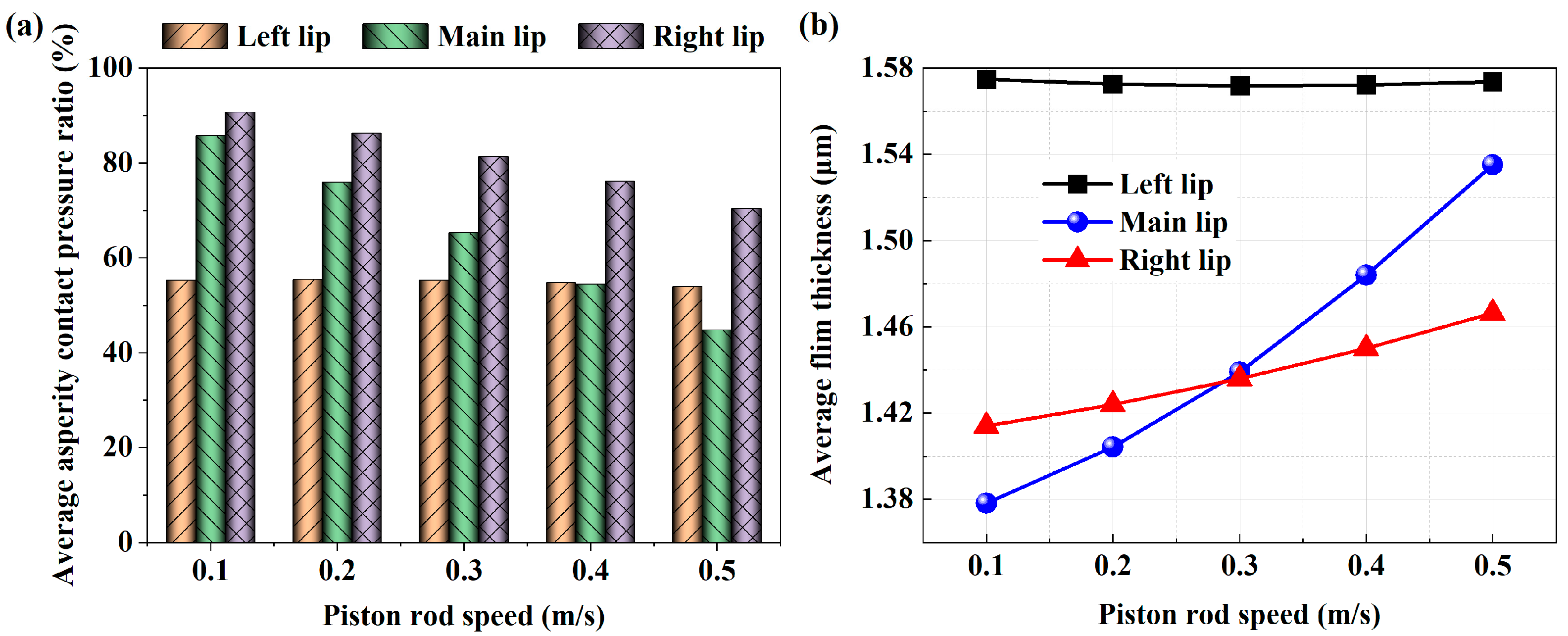
4.3.2. Effect of Piston Rod Speed

Figure 6 shows that when ps = 4 MPa and σ = 0.6 μm, there is an effect of different extension speeds on the seal lubrication characteristics. The average asperity contact pressure ratio between the main lip and the right lip shows a significant decreasing trend, as seen in Figure 6a. This is because as the sealed pressure is constant, the static contact pressure remains unchanged. When the piston rod speed increases, the hydrodynamic effect increases the film pressure, but the sum of the film pressure and the asperity contact pressure remains unchanged, so the proportion of the asperity contact pressure of the corresponding roughness of the main lip and the right lip decreases. The asperity contact pressure ratio of the left lip displays a slight convex shape as the extension speed is increased from 0.1 m/s to 0.5 m/s. When the speed is less than 0.3 m/s, the asperity contact pressure ratio remains positively correlated with the speed. The asperity contact pressure gradually decreases with increasing speed as speed increases over 0.3 m/s. This indicates that there is a critical speed near the piston rod extension speed of 0.3 m/s, which changes the variation trend of the asperity contact pressure on the left lip. Figure 6b demonstrates that the sealing zone is in a mixed lubrication state since the ratio of the average film thickness to the seal roughness of the three lips at different piston rod speeds is less than 3. The average film thickness of the main lip and the right lip in the sealing zone increases obviously as the extension speed rises, while the average film thickness of the left lip presents a slight concave shape, with the minimum film thickness near the speed of 0.3 m/s, which is consistent with the reason revealed in Figure 6a. At the same time, it further shows that there is strong coupling state in the working process of the multi-lip seal, and the lubrication characteristics of each seal lip are not consistent.

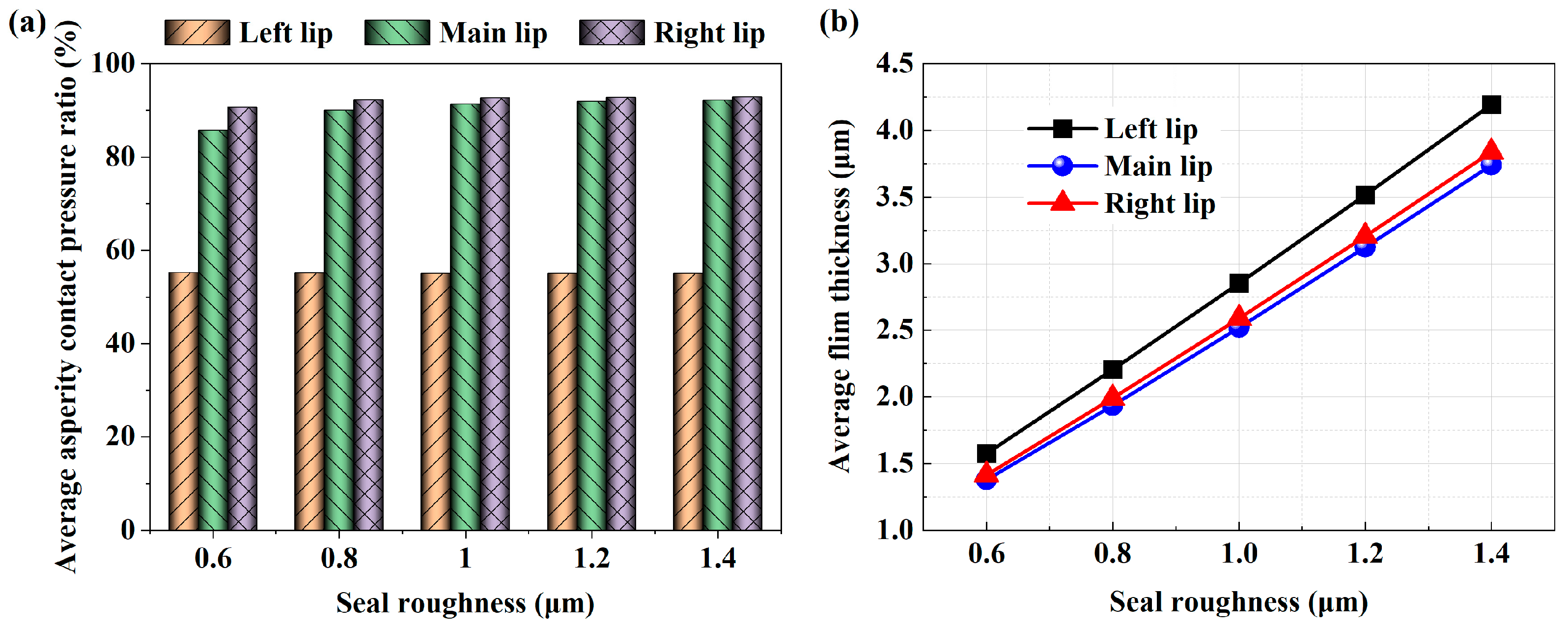
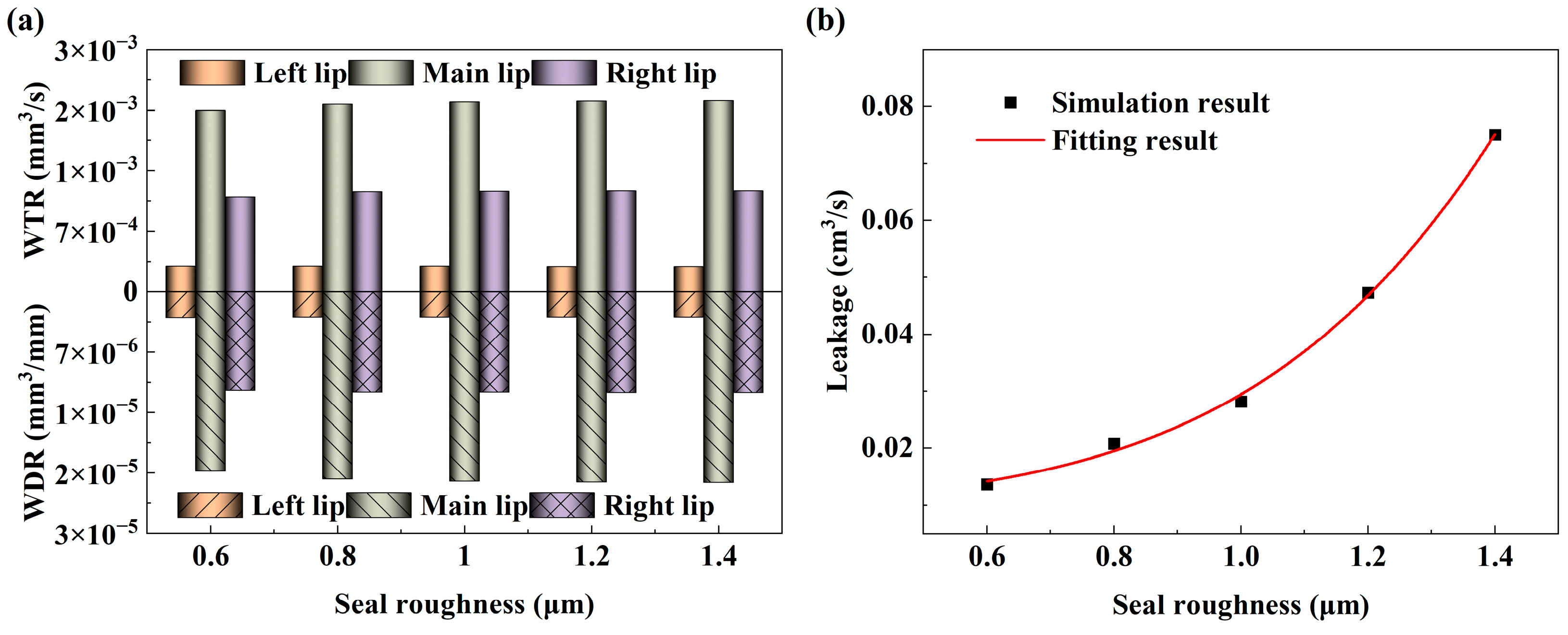
4.3.3. Effect of Seal Roughness

Figure 7 illustrates the variation in the average asperity contact pressure ratio and average film thickness under various seal roughness. Figure 7a demonstrates that as the seal roughness increases, the asperity contact pressure ratio also rises. Once the sealed pressure is determined, the load undertaken by the film fluid and the seal asperity peak are added together and remain constant. Therefore, it is further explained that when the roughness increases, the film fluid pressure decreases. The rougher the seal surface, the weaker the hydrodynamic pressure effect and the worse the lubrication performance. Figure 7b shows the average film thickness of the three lips under different seal roughness. It can be seen that as the roughness rises from 0.6 μm to 1.4 μm, the average film thickness of the three lips basically presents a linear rise trend, in which left lip is the maximum and the main lip is the minimum. The static contact pressure of the main lip is at maximum under a certain sealed pressure, and an increase in seal roughness will inevitably result in an increase in the seal clearance gap. Therefore, the increase in the main lip sealing zone clearance gap relative to the left and right lip is the minimum with an increase in seal roughness. In addition, full film fluid lubrication occurs under this roughness in the sealing zone of the left lip when the roughness is 1.4 μm.

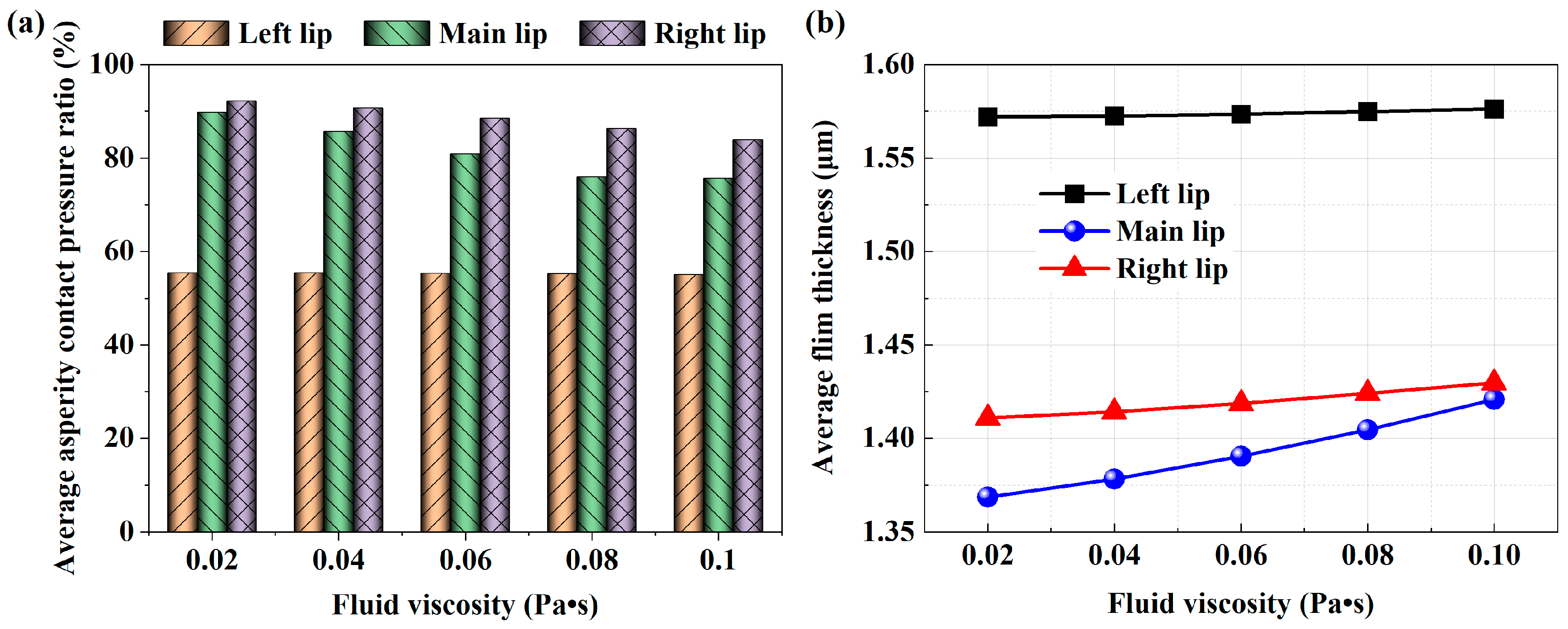
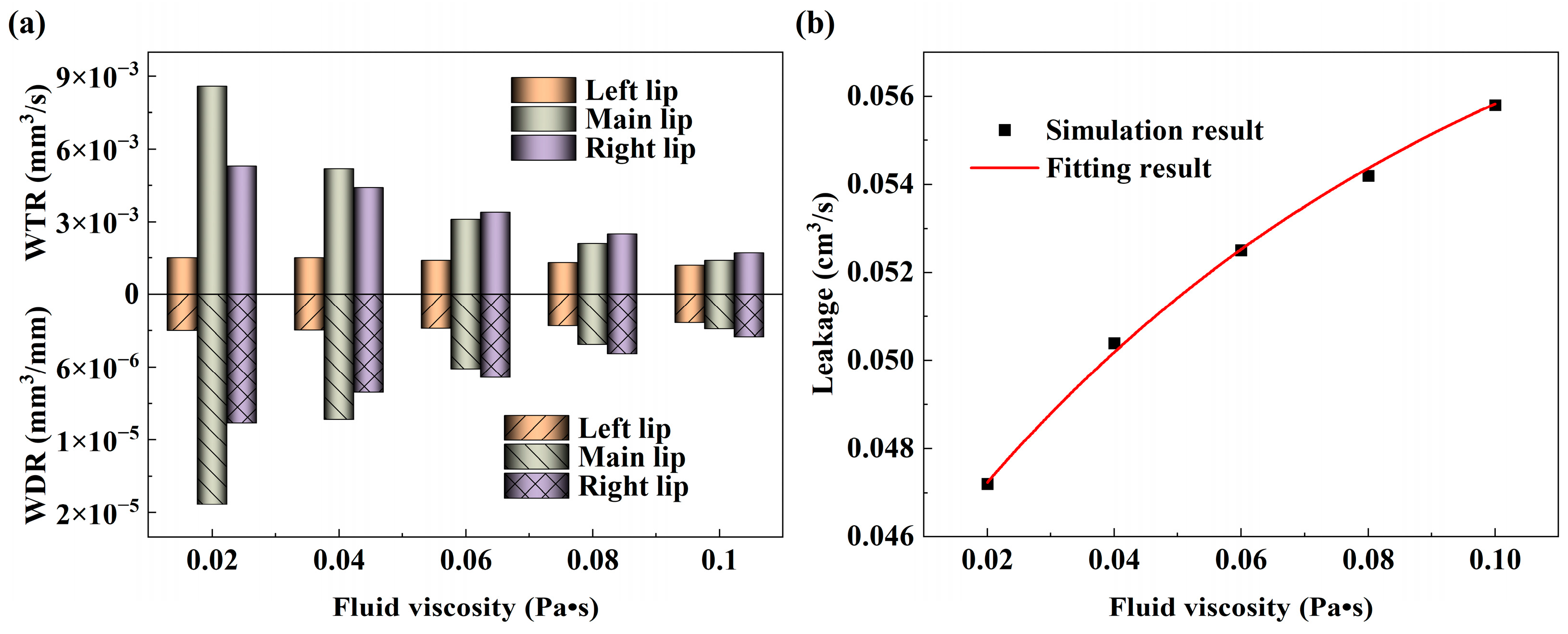
4.3.4. Effect of Fluid Viscosity

As ps = 4 MPa, u = 0.1 m/s and σ = 0.6 μm, the influence of the asperity contact pressure ratio and average film thickness for various fluid viscosities is shown in Figure 8. The asperity contact pressure ratio of the three seal lips gradually decreases as the fluid viscosity gradually increases from 0.02 Pa·s to 0.10 Pa·s, as shown in Figure 8a. In general, the viscous shear effect becomes stronger with the rises in fluid viscosity, and the hydrodynamic pressure effect of the film fluid is enhanced accordingly. This conclusion is also given in Wang et al. [34]. According to Figure 8b, the average film thickness of the three seal lips in the sealing zone is proportional to the increase in fluid viscosity, and the variation range of the film thickness is 1.57~1.58 μm, 1.36~1.42 μm and 1.41~1.43 μm, respectively. This is because when the fluid viscosity increases, the interaction between the molecules within the fluid can hinder the fluidity of the fluid in the sealing zone, which increases the average film thickness and reduces the chance of asperity peak contact. Therefore, the selection of high-viscosity fluid is helpful to reduce the Coulomb friction force and seal wear caused by the seal roughness. On the contrary, the viscous friction force will increase accordingly.

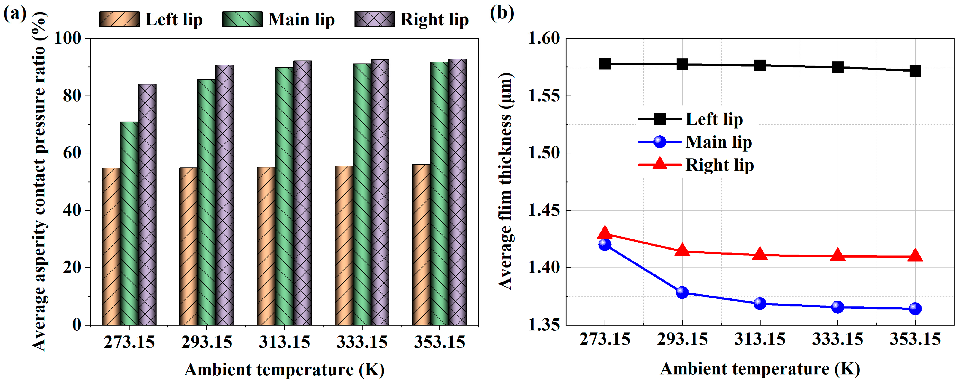
4.3.5. Effect of Ambient Temperature

The asperity contact pressure ratio and average film thickness at various ambient temperatures are shown in Figure 9. When ps = 4 MPa, u = 0.1 m/s and σ = 0.6 μm, the influence of asperity contact pressure ratio at various ambient temperatures is depicted in Figure 9a. As the ambient temperature rises, the asperity contact pressure ratio of the three seal lips in the sealing zone gradually increases. According to Equation (9), the fluid viscosity is a combined effect of temperature and pressure. The high-temperature environment will cause an increase in asperity contact pressure and a decrease in film fluid pressure, which will eventually lead to a decrease in film fluid load capacity and an increase in the asperity contact pressure ratio. The average film thickness of the three seal lips at various ambient temperatures is shown in Figure 9b. When the ambient temperature gradually increased from 273.15 K to 353.15 K, the film thickness gradually decreased. It is worth noting that when the ambient temperature is from 273.15 K to 293.15 K, the film thickness of the main lip and right lip decreases sharply. When the ambient temperature is greater than 293.15 K, the film thickness decreases slowly, which is mostly caused by the comprehensive effect of the ambient temperature and fluid pressure on the fluid viscosity. As can be noticed, the average film thickness of the left lip is maximum, while the average film thickness of the main lip is minimum. According to Figure 3d, when the seal is deformed, the static contact pressure of the main lip is the maximum, and the static contact pressure of the left lip is the minimum. The large static contact pressure makes the seal lip and the cylinder wall more tightly squeezed, so the average film thickness is the thinnest.

4.4. Analysis of Seal Wear Characteristics

4.4.1. Effects of Sealed Pressure

As u = 0.1 m/s and σ = 0.6 μm, the effects of various sealed pressures on the seal wear characteristics are depicted in Figure 10. The WTR and WDR of the three seal lips rapidly rise as the sealed pressure rises from 2 MPa to 10 MPa, as seen in Figure 10a. The WTR increased in the ranges of 1.0931 × 10⁻⁴~6.8548 × 10⁻⁴ mm3/s, 0.0013~0.0047 mm3/s and 5.0752 × 10⁻⁴~0.0036 mm3/s, respectively. Figure 10b illustrates the effect of sealed pressure on leakage. Significantly, the leakage reduces as the sealed pressure rises as the piston rod speed remains constant. This is due to the fact that, as the piston rod extends, the cylinder interior moves in the opposite direction. The Poiseuille flow caused by the pressure difference hinders the Couette flow caused by the speed, resulting in the gradual leakage of fluid from the high-pressure side to the low-pressure side. The greater the medium pressure, the more significant the effect of Poiseuille flow. At the same time, it can be seen from Figure 5 that the greater the sealed pressure, the smaller the film thickness. Therefore, it is a challenge to find a seal with a long life or good dependability when there is high sealed pressure at work.

4.4.2. Effects of Piston Rod Speed

Figure 11 depicts the effects of the extension speed from 0.1 m/s to 0.5 m/s on the seal wear characteristics. As shown in Figure 11a, as the extension speed rises, the WTR of the three seal lips increased from 2.9742 × 10⁻⁴ mm3/s, 0.0021 mm3/s and 0.0011 mm3/s to 0.0015 mm3/s, 0.0052 mm3/s and 0.0044 mm3/s, while the WDR decreased from 2.9742 × 10⁻⁶ mm3/mm, 2.0770 × 10⁻⁵ mm3/mm and 1.1426 × 10⁻⁵ mm3/mm to 2.9676 × 10⁻⁶ mm3/mm, 1.0323 × 10⁻⁵ mm3/mm and 8.8675 × 10⁻⁶ mm3/mm, respectively. As mentioned above, the hydrodynamic effect is enhanced when the extension speed rises, so that the film thickness increases and the number of asperity contact peaks decreases, resulting in reduced asperity contact pressure. Therefore, the leakage rises as the extension speed increases, as seen in Figure 11b.

4.4.3. Effects of Seal Roughness

For ps = 4 MPa and u = 0.1 m/s, the effects of different seal surface roughness on seal wear characteristics are shown in Figure 12. With the roughness increasing from 0.6 μm to 1.4 μm, the WTR and WDR of the seal lip showed an increasing trend, as displayed in Figure 12a. When the roughness increased from 0.6μm to 0.8 μm, the WTR and WDR of the main lip and right lip increased sharply. When the roughness is larger than 0.8 μm, the wear rate increases slowly. Figure 12b depicts the impact of different seal roughness on leakage. As the roughness rises, it is evident that the leakage also increases. According to Figure 7, the difference in film thickness distribution caused by the increase in roughness is not caused by an enhancement in the hydrodynamic pressure effect but by an increase in the roughness peak height, which leads to an increase in the seal clearance gap and stored fluid, so the fluid leakage increases correspondingly.

4.4.4. Effects of Fluid Viscosity

As ps = 4 MPa and u = 0.5 m/s, Figure 13 illustrates the influence of different fluid viscosity on seal wear characteristics. Figure 13a shows that both the WTR and WDR of the seal lip decrease sharply when the fluid viscosity rises from 0.02 Pa·s to 0.10 Pa·s. The main reason is that the fluidity of high-viscosity fluid is poorer than that of low-viscosity fluid, which leads to the fluid being stored in the seal clearance gap, increasing the film thickness and eventually leading to the separation of the seal lip from the cylinder inner wall, thus reducing the Coulomb friction generated by the asperity contact between the seal surface rough peak and the cylinder inner wall. This result corresponds with the increase in fluid viscosity reducing the asperity contact pressure ratio, as seen in Figure 8. The variation trend of seal leakage with fluid viscosity is shown in Figure 13b. As the fluid viscosity rises, it is evident that leakage also rises. This is mainly due to the increase in fluid viscosity, resulting in greater viscous shear stress. When the sealed pressure and the piston rod speed remain constant, the hydrodynamic effect of viscous fluid is stronger, and more fluid is dragged into the seal clearance gap; thus, the leakage increases due to the Couette flow caused by the movement.

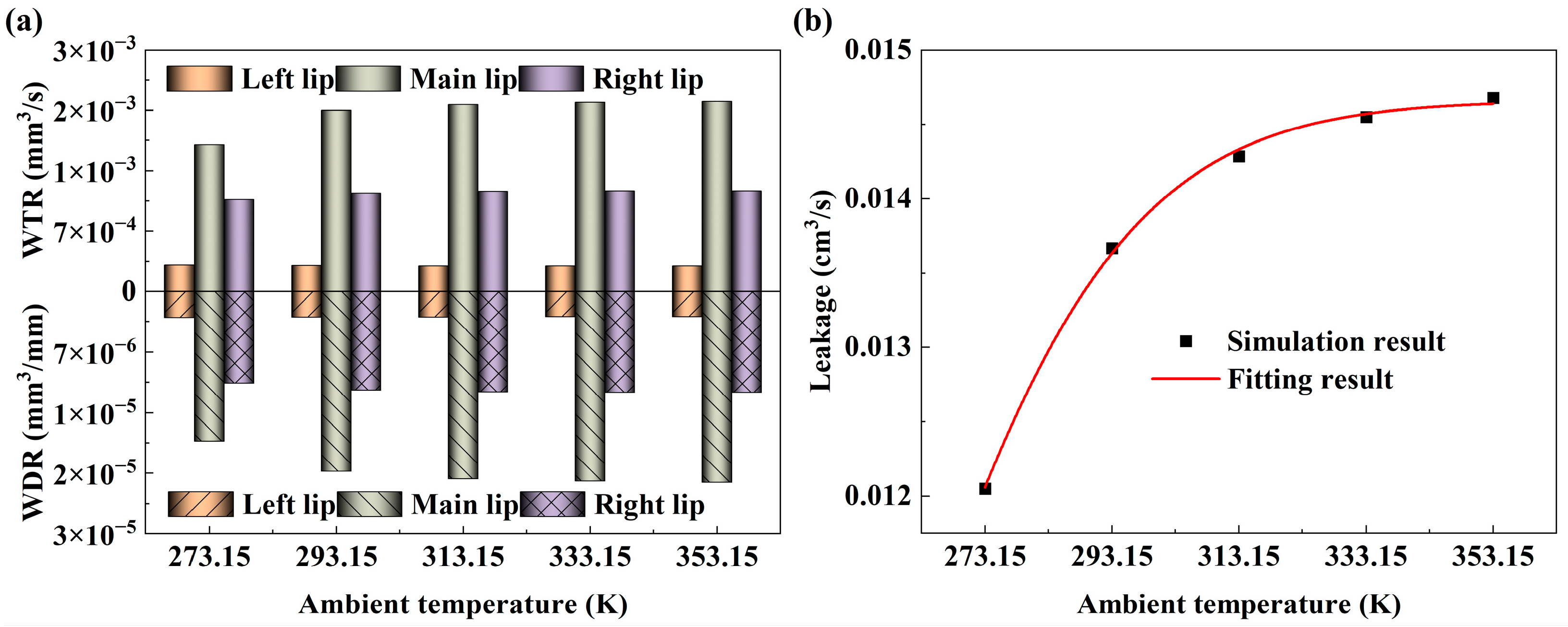
4.4.5. Effects of Ambient Temperature

Figure 14 shows the effect of ambient temperature on seal wear. From Figure 14a, when the ambient temperature rises from 273.15 K to 353.15 K, the WTR and WDR of the main lip and right lip increased sharply and then slowly, while the left lip increased slightly, which is consistent with the trend of asperity contact pressure ratio with ambient temperature in Figure 9a. It further shows that the high-temperature environment will reduce the film fluid load capacity and increase the asperity contact pressure. The friction mainly comes from the micro asperity contact pressure. The high temperature leads to increased friction, and friction heat makes the temperature higher, which forms positive feedback to aggravate the friction and wear of the seal. It is extremely detrimental to the seal, so the appropriate seal at the right ambient temperature should be chosen. Figure 14b shows the influence of ambient temperature on leakage. It is evident that when the ambient temperature rises, the leakage quantity also increases rapidly and then slowly rises, which is the same as the trend in Figure 14a. The fluid viscosity decreases with the temperature increase, which improves the fluidity and the Poiseuille increases. As can be seen from Figure 13, the greater the fluid viscosity, the greater the leakage caused by shear flow. Therefore, the influence of fluid viscosity and temperature on leakage must be considered comprehensively.

5. Conclusions

In order to explore the wear characteristics of a multi-lip reciprocating seal under lubrication conditions, a numerical calculation method of M-TEHL wear is established by introducing the energy equation and the modified Archard equation based on the isothermal M-EHL theory. Through this method, the relationship between solid mechanics, fluid mechanics and thermal mechanics in the sealing zone is strongly coupled. The influence of different sealed pressures, piston rod speeds, seal surface roughness and other conditions on seal lubrication and wear behavior is numerically studied. Finally, the following conclusions are obtained from the simulation results:
  • Some characteristics of the single-lip seal are also reflected in the DAS multi-lip combined seal. The increase in sealed pressure decreases the sealed performance and increases the seal wear rate. When the piston rod speed is increased, the WTR also increases. The high-temperature environment leads to the deterioration of the lubrication characteristics in the sealing zone and increases the seal wear. Therefore, it is not difficult to find that high pressure, high speed and high temperature are still great challenges for the lip seal.
  • The load on the sealing zone under mixed lubrication is mainly shared by asperity contact, and the asperity contact load is as high as 50%. When the roughness is greater than 0.6 μm, the seal wear rate clearly increases. Therefore, smaller surface roughness is more conducive in reducing the seal wear and fluid leakage.
  • The lubrication characteristics of each seal lip in a DAS multi-lip combined seal largely depend on the working conditions. In the piston rod extension motion, the sealing behavior of each seal lip is not identical due to the existence of critical speed.
It should be emphasized that the model in this paper is established in steady-state conditions and cannot be directly used to the calculation under unsteady-state conditions. Therefore, the transient-state effect should be considered in future research.

Author Contributions

Conceptualization, D.C. and L.G.; methodology, D.C.; software, D.C.; validation, D.C., L.G. and Y.S. (Yu Sun); formal analysis, L.G. and Y.S. (Yuan Shi); investigation, D.C.; resources, L.G.; data curation, D.C., L.G. and Y.S. (Yu Sun); writing—original draft preparation, D.C.; writing—review and editing, L.G.; supervision, L.G. and Y.S. (Yuan Shi); project administration, L.G. All authors have read and agreed to the published version of the manuscript.

Funding

This research was funded by the National Natural Science Foundation of China (grant no. 51675399) and Fundamental Research Funds for the Central Universities, CHD (grant no. 300102252506).

Data Availability Statement

Not applicable.

Conflicts of Interest

The authors declare no conflict of interest.

Nomenclature

ccSpecific heat capacity of the cylinder wall
DcInsider diameter of cylinder
EElastic modulus
FCavitation index
FnNormal force
fcFriction coefficient for asperity contact
HDimensionless average film thickness, h/σ
HBHardness of the seal material
HsDimensionless static film thickness, hs/σ
HTDimensionless average truncated film thickness, hT/σ
hwSeal wear depth
KDeformation coefficient matrix
kcThermal conductivity of the cylinder wall
knSeal material wear coefficient, Kn/HB
LContact length of sealing zone
LstrokeCylinder stroke length
LRelative sliding distance
PcDimensionless asperity contact pressure, pc/E
PfDimensionless fluid film pressure, pf/pa
Pi1, Pi2Pressure in the first and second inter-lip region
PlDimensionless pressure in low-pressure side, pl/pa
PsDimensionless sealed pressure, ps/pa
PscDimensionless static contact pressure, psc/E
paAmbient pressure
pnNormal contact pressure
QHeat production rate of the cylinder wall, τ ^ f + τ ^ c E u
q ^ Dimensionless flow rate, 12 μ 0 q L / ( p a σ 3 )
RRadius of asperities
TFluid film temperature
T0Ambient temperature
UDimensionless piston rod speed, μ 0 u L / ( p a σ 2 )
VwSeal wear volume
x ^ Dimensionless coordinate parallel to the fluid film thickness, x/L
zDimensionless coordinate normal to the fluid film thickness
αViscosity-pressure coefficient
α ^ Dimensionless pressure-viscosity coefficient, αpa
βViscosity-temperature coefficient
ξ R 1 / 3 η 2 / 3 E s L / P a
ΦFluid pressure/density function
ϕf, ϕfs, ϕfpShear stress factors
ϕs.c.x, ϕxxFlow factor
ηAsperity density
μ0Fluid viscosity at atmospheric pressure
ρcDensity of the cylinder wall
vPoisson’s ratio
ρfFluid density
ρ ^ Dimensionless density, ρ/ρf
σ ^ Dimensionless RMS roughness of the seal, σR1/3η2/3
τ ^ f Dimensionless viscous shear stress, τ f / E
τ ^ c Dimensionless asperity shear stress, τ c / E

Abbreviations

DASDouble-acting seal
FEAFinite element analysis
FEMFinite element method
M-EHLMixed elastohydrodynamic lubrication
M-TEHLMixed thermal elastohydrodynamic lubrication
NBRNitrile rubber
PTFEPolytetrafluoroethylene
POMPolyformaldehyde
RMSRoot mean square
TPEThermoplastic polyester elastomer
WTRWear time rate
WDRWear distance rate

Appendix A

The G-W contact model [26] states that the asperity contact pressure of the seal surface may be expressed as
p c = 4 3 E σ 3 / 2 R 1 / 2 η H ( z H ) 3 / 2 Γ ( z ) d z
where Γ(z) is the probability density function of the asperity peak. E′ is the equivalent elastic modulus of the two surfaces, expressed as
1 E = 1 ν c 2 E c + 1 ν s 2 E s
where Es, Ec, vs and vc are the elastic modulus and Poisson’s ratio of the seal ring and cylinder, respectively.
Since the elastic modulus of the cylinder is much larger than that of the seal, the equivalent elastic modulus can be simplified as
E = E s 1 ν s 2
Substituting Equation (A3) into Equation (A1), the asperity contact pressure is
p c = 4 3 E s 1 ν s 2 σ 3 / 2 R 1 / 2 η H ( z H ) 3 / 2 Γ ( z ) d z
Since the seal surface asperities obey Gaussian distribution,
Γ ( z ) = 1 2 π e z 2 / 2
Substituting Equation (A5) into Equation (A4), the asperity contact pressure is
p c = 4 3 E s 1 ν s 2 σ 3 / 2 R 1 / 2 η 1 2 π H ( z H ) 3 / 2 e z 2 / 2 d z
The dimensionless asperity pressure is defined as
P c = p c E s
The dimensionless asperity pressure can be expressed as
P c = 4 3 1 ( 1 v s 2 ) σ 3 / 2 R 1 / 2 η 1 2 π H ( z H ) 3 / 2 e z 2 / 2 d z

References

  1. Guo, F.; Jia, X.H.; Wang, L.K.; Salant, R.F.; Wang, Y.M. The Effect of Wear on t Performance of a Rotary Lip Seal. J. Tribol. 2014, 136, 0417031–0417038. [Google Scholar] [CrossRef] [PubMed] [Green Version]
  2. Zhao, X.X.; He, X.Y.; Wang, L.T.; Chen, P. Research on pressure compensation and friction characteristics of piston rod seals with different degrees of wear. Tribol. Int. 2020, 142, 105999. [Google Scholar] [CrossRef]
  3. Paige, J.; Stephens, L.S. Surface Characterization and Experimental Design for Testing of a Radial Lip Seal. Tribol. Trans. 2004, 47, 341–355. [Google Scholar] [CrossRef]
  4. Hao, L.C.; Meng, Y.G. Numerical Prediction of Wear Process of an Initial Line Contact in Mixed Lubrication Conditions. Tribol. Lett. 2015, 60, 31. [Google Scholar] [CrossRef]
  5. Ridgway, N.; Colby, C.B.; O’Neill, B.K. Slurry pump gland seal wear. Tribol. Int. 2009, 42, 1715–1721. [Google Scholar] [CrossRef]
  6. Yang, X.B.; Jin, X.Q.; Du, Z.M.; Cui, T.S.; Yang, S.K. Frictional behavior investigation on three types of PTFE composites under oil-free sliding conditions. Ind. Lubr. Tribol. 2009, 61, 254–260. [Google Scholar] [CrossRef]
  7. Lee, S.H.; Yoo, S.S.; Kim, D.E.; Kang, B.S.; Kim, H.E. Accelerated wear test of FKM elastomer for life prediction of seals. Polym. Test. 2012, 31, 993–1000. [Google Scholar] [CrossRef]
  8. Wang, J.L.; Jia, Q.; Yuan, X.Y.; Wang, S.P. Experimental study on friction and wear behaviour of amorphous carbon coatings for mechanical seals in cryogenic environment. Appl. Surf. Sci. 2012, 258, 9531–9535. [Google Scholar] [CrossRef]
  9. Liu, Y.L.; Tang, D.; Liu, J.; John, L. Wear behaviour of piston seals in flow meter of fuel dispenser under different pressure conditions. Flow Meas. Instrum. 2012, 28, 45–49. [Google Scholar] [CrossRef]
  10. Gao, S.Y.; Xue, W.H.; Duan, D.L.; Li, S.; Zheng, H.L. Effect of thermal-physical properties on the abradability of seal coating under high-speed rubbing condition. Wear 2018, 394, 20–29. [Google Scholar] [CrossRef]
  11. Kozuch, E.; Nomikos, P.; Rahmani, R.; Morris, N.; Rahnejat, H. Effect of Shaft Surface Roughness on the Performance of Radial Lip Seals. Lubricants 2018, 6, 99. [Google Scholar] [CrossRef] [Green Version]
  12. Nomikos, P.; Rahmani, R.; Morris, N.; Rahnejat, H. An investigation of oil leakage from automotive driveshaft radial lip seals. Proc. Inst. Mech. Eng. Part D J. Aut. Eng. 2022, 1–17. [Google Scholar] [CrossRef]
  13. Yang, L.M.; Moan, T. Numerical Modeling of Wear Damage in Seals of a Wave Energy Converter with Hydraulic Power Take-Off under Random Loads. Tribol. Trans. 2010, 54, 44–56. [Google Scholar] [CrossRef]
  14. Békési, N.; Váradi, K.; Felhős, D. Wear Simulation of a Reciprocating Seal. J. Tribol. 2011, 133, 031601. [Google Scholar] [CrossRef]
  15. Frölich, D.; Magyar, B.; Sauer, B. A comprehensive model of wear, friction and contact temperature in radial shaft seals. Wear 2014, 311, 71–80. [Google Scholar] [CrossRef]
  16. Li, X.; Peng, G.L.; Li, Z. Prediction of seal wear with thermal–structural coupled finite element method. Finite Elem. Anal. Des. 2014, 83, 10–21. [Google Scholar] [CrossRef]
  17. Xiang, C.; Guo, F.; Jia, X.H.; Wang, Y.M.; Huang, X. Thermo-elastohydrodynamic mixed-lubrication model for reciprocating rod seals. Tribol. Int. 2019, 140, 105894. [Google Scholar] [CrossRef]
  18. Salant, R.F.; Flaherty, A.L. Elastohydrodynamics of lip seals. Lubr. Sci. 1995, 8, 15–26. [Google Scholar] [CrossRef]
  19. Zhang, Y.; Xiong, S.Y.; Zhong, S.P.; Xiong, Z.J.; Yang, Q. Solution and analysis of VL combined seal lubrication model under the effect of wear. J. Mech. Sci. Technol. 2022, 36, 5599–5609. [Google Scholar] [CrossRef]
  20. Liu, D.; Wang, S.P.; Zhang, C. A multiscale wear simulation method for rotary lip seal under mixed lubricating conditions. Tribol. Int. 2018, 121, 190–203. [Google Scholar] [CrossRef]
  21. Ran, H.L.; Wang, S.P.; Liu, D. A multiscale wear model for reciprocating rod stepseal under mixed lubricating conditions based on linear elasticity. Proc. Inst. Mech. Eng. Part J J. Eng. Tribol. 2020, 235, 161–180. [Google Scholar] [CrossRef]
  22. Cheng, D.H.; Gu, L.C.; Sun, Y. Mixed Lubrication Modeling of Multi-Lip Reciprocating Seals Based on Elastohydrodynamic Lubrication Theory. Machines 2022, 10, 483. [Google Scholar] [CrossRef]
  23. Salant, R.F.; Yang, B.; Thatte, A. Simulation of hydraulic seals. Proc. Inst. Mech. Eng. Part J J. Eng. Tribol. 2010, 224, 865–876. [Google Scholar] [CrossRef]
  24. Patir, N.; Cheng, H.S. An Average Flow Model for Determining Effects of Three-Dimensional Roughness on Partial Hydrodynamic Lubrication. J. Lubr. Technol. 1978, 100, 12–17. [Google Scholar] [CrossRef]
  25. Patir, N.; Cheng, H.S. Application of Average Flow Model to Lubrication between Rough Sliding Surfaces. J. Lubr. Technol. 1979, 101, 220–229. [Google Scholar] [CrossRef]
  26. Greenwood, J.A.; Williamson, J.B.P. Contact of nominally flat surfaces. Proc. R. Soc. Lond. A. 1966, 295, 300–319. [Google Scholar] [CrossRef]
  27. Gadari, M.E.; Fatu, A.; Hajjam, M. Shaft roughness effect on elasto-hydrodynamic lubrication of rotary lip seals: Experimentation and numerical simulation. Tribol. Int. 2015, 88, 218–227. [Google Scholar] [CrossRef]
  28. Yang, B.; Salant, R.F. Elastohydrodynamic lubrication simulation of O-ring and U-cup hydraulic seals. Proc. Inst. Mech. Eng. Part J J. Eng. Tribol. 2011, 225, 603–610. [Google Scholar] [CrossRef]
  29. Roelands, C.J.A. Correlational Aspects of the Viscosity-Temperature-Pressure Relationship of Lubricating Oils. Ph.D. Thesis, Deft University of Technology, Delft, Netherlands, 1966. [Google Scholar]
  30. Archard, J.F. Contact and Rubbing of Flat Surfaces. J. Appl. Phys. 1953, 24, 981–988. [Google Scholar] [CrossRef]
  31. Ran, H.L.; Liu, D.; Wang, S.P. A Numerical Wear Simulation Method of Reciprocating Seals with a Textured Rod. Materials 2020, 13, 4458. [Google Scholar] [CrossRef]
  32. Zhang, J.; Xie, J. Investigation of static and dynamic seal performances of a rubber O-ring. J. Tribol. 2018, 140, 042202. [Google Scholar] [CrossRef]
  33. Xiang, C.; Guo, F.; Jia, X.H.; Wang, Y.M. Numerical simulation model of reciprocating rod seal systems with axial wear texture on rod surface. Lubr. Sci. 2023, 1–19. [Google Scholar] [CrossRef]
  34. Wang, B.Q.; Peng, X.D.; Meng, X.K. Simulation of the effects of non-Newtonian fluid on the behavior of a step hydraulic rod seal based on a power law fluid model. J. Zhejiang Univ. Sci. A 2018, 19, 824–842. [Google Scholar] [CrossRef]
Figure 1. Schematic of the hydraulic cylinder: (a) assembly structure, (b) piston seal structure.
Lubricants 11 00248 g001
Figure 2. Scheme of computational procedure.
Lubricants 11 00248 g002
Figure 3. FEA of DAS-combined seal: (a) FEA meshing model, (b) the von Mises stress after assembly and pressurization, (c,d) the nephogram and curve of static contact pressure distribution.
Lubricants 11 00248 g003
Figure 4. Film pressure comparison: (a) left lip, (b) main lip and (c) right lip.
Lubricants 11 00248 g004
Figure 5. Lubrication situation under different sealed pressure: (a) average asperity contact pressure ratio, (b) average film thickness.
Lubricants 11 00248 g005
Figure 6. Lubrication situation under different piston rod speeds: (a) average asperity contact pressure ratio, (b) average film thickness.
Lubricants 11 00248 g006
Figure 7. Lubrication situation under different seal roughness: (a) average asperity contact pressure ratio, (b) average film thickness.
Lubricants 11 00248 g007
Figure 8. Lubrication situation under different fluid viscosity: (a) average asperity contact pressure ratio, (b) average film thickness.
Lubricants 11 00248 g008
Figure 9. Lubrication situation under different ambient temperature: (a) average asperity contact pressure ratio, (b) average film thickness.
Lubricants 11 00248 g009
Figure 10. Wear situation under different sealed pressure: (a) wear rate, (b) leakage.
Lubricants 11 00248 g010
Figure 11. Wear situation under different piston rod speeds: (a) wear rate, (b) leakage.
Lubricants 11 00248 g011
Figure 12. Wear situation under different seal roughness: (a) wear rate, (b) leakage.
Lubricants 11 00248 g012
Figure 13. Wear situation under different fluid viscosity: (a) wear rate, (b) leakage.
Lubricants 11 00248 g013
Figure 14. Wear situation under different ambient temperatures: (a) wear rate, (b) leakage.
Lubricants 11 00248 g014
Table 1. Main simulation parameters.
Parameter TypeValue
Ambient temperature, T0273.15~313.15 K
Ambient pressure, p00.1 MPa
Fluid viscosity, μ00.02~0.10 Pa·s
Viscosity-pressure coefficient, α2 × 10⁻⁸ Pa−1
Viscosity-temperature coefficient, β3.17908 × 10⁻² K−1
Sealed pressure, ps2~10 MPa
Wear coefficient, kn1.2 × 10−5 mm3/Nm [31]
Stroke length, Lstroke300 mm
Insider diameter of cylinder, Dc63 mm
Piston rod extension speed, u0.1~0.5 m/s
Seal RMS roughness, σ0.6~1.4 μm
Friction coefficient, fc0.1 [32,33]
Thermal conductivity of cylinder wall, kc46 W/(m·K)
Density of cylinder wall, ρc7850 kg/m3
Specific heat capacity of cylinder wall, cc460 J/(kg·K)
Disclaimer/Publisher’s Note: The statements, opinions and data contained in all publications are solely those of the individual author(s) and contributor(s) and not of MDPI and/or the editor(s). MDPI and/or the editor(s) disclaim responsibility for any injury to people or property resulting from any ideas, methods, instructions or products referred to in the content.

