Tool Wear and Surface Integrity of γ-TiAl Cryogenic Coolant Machining at Various Cutting Speed Levels


Abstract
:1. Introduction
2. Experimental Preparation
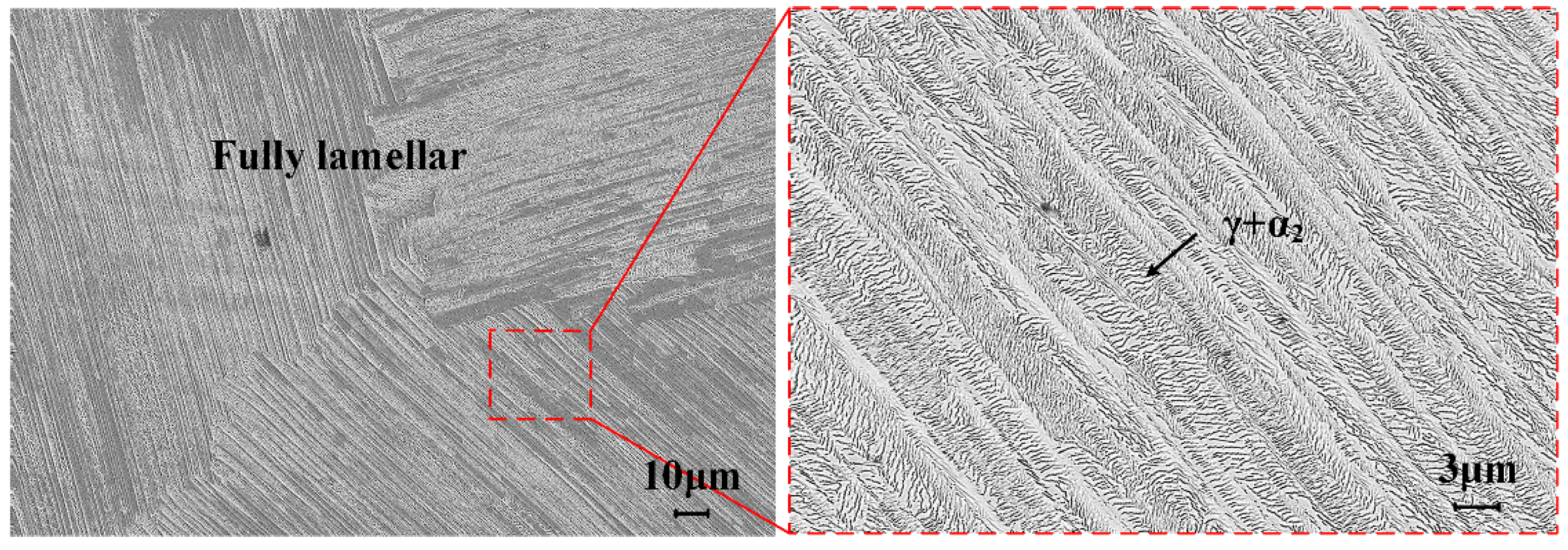
2.1. Workpiece Materials
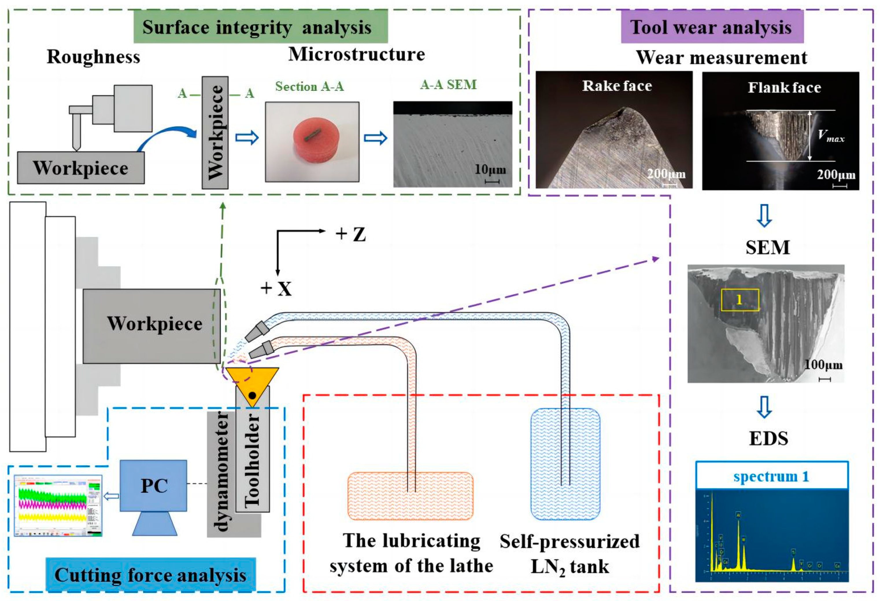
2.2. Experimental Conditions and Processes
3. Results and Discussion
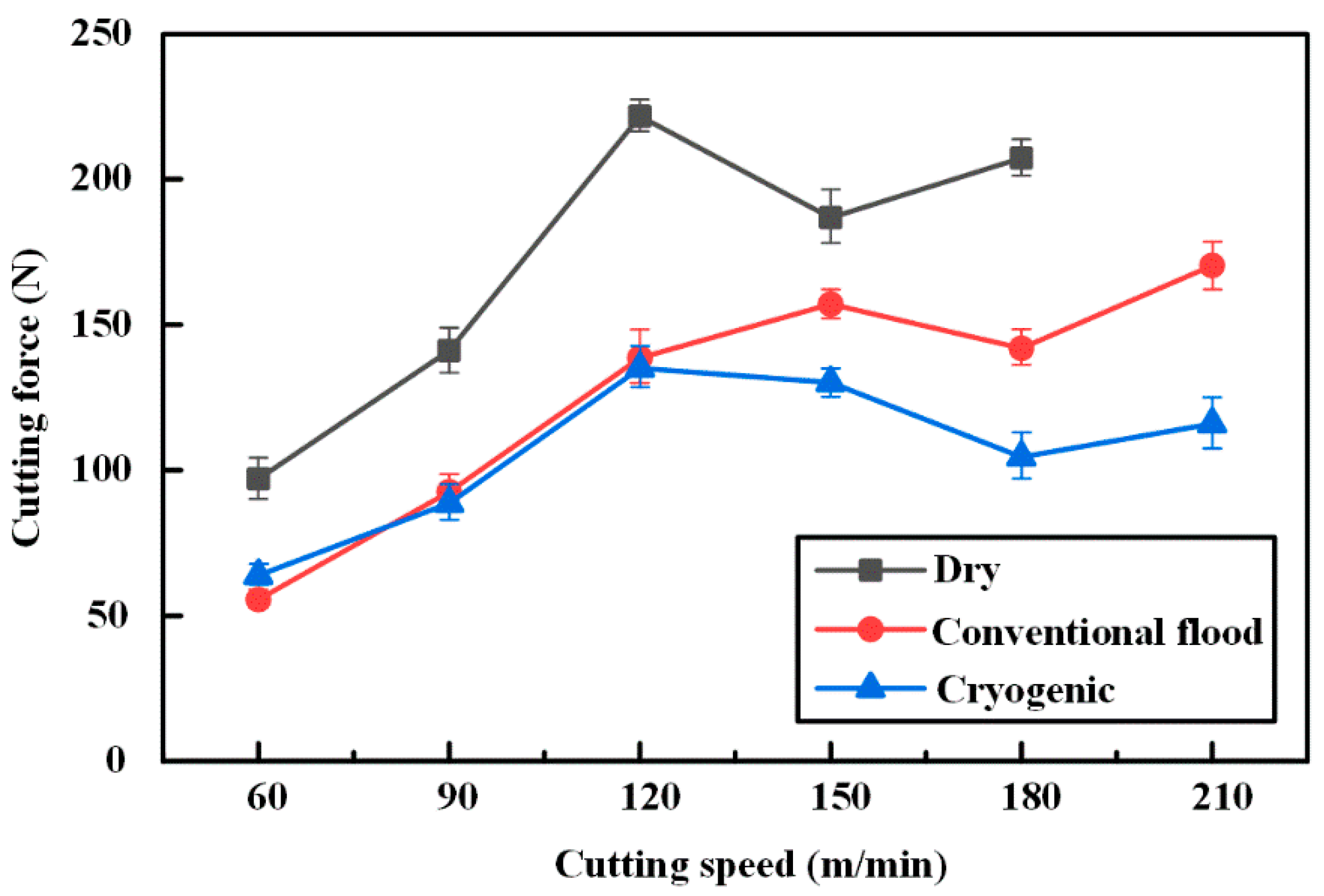
3.1. Cutting Force
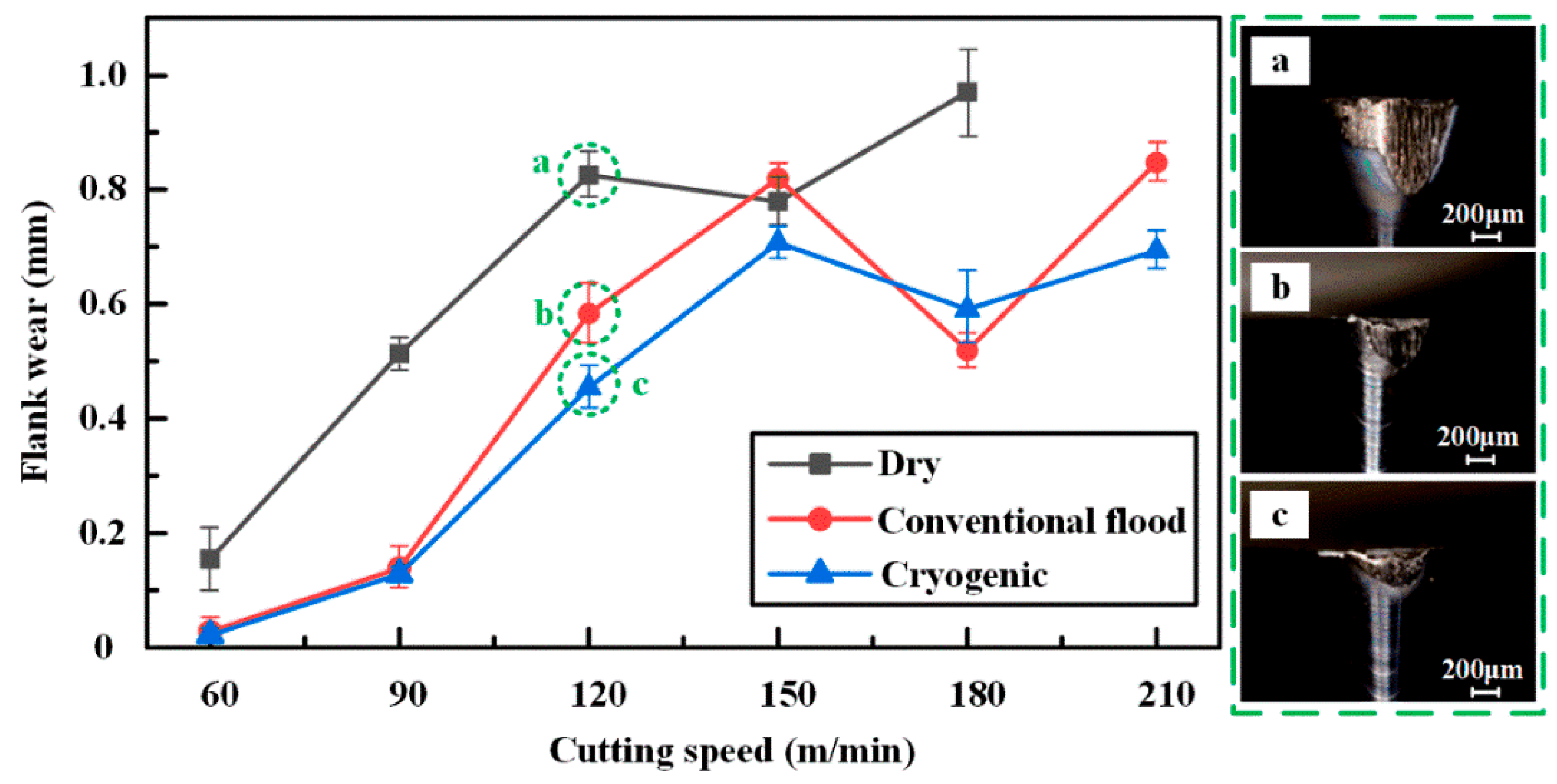
3.2. Tool Wear
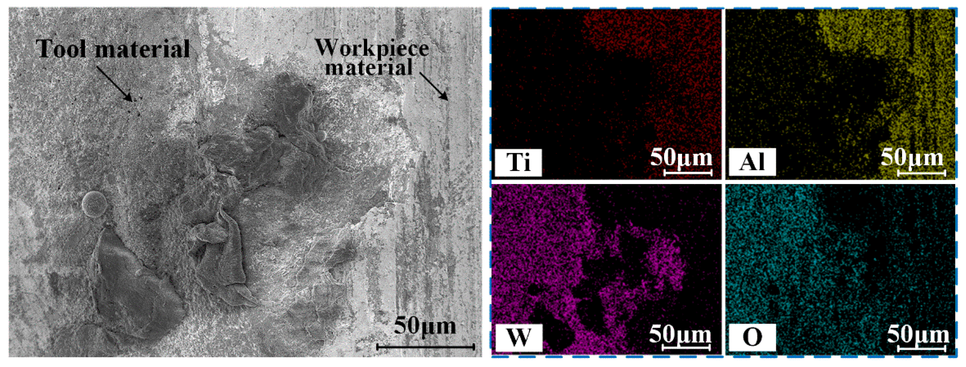
3.3. Wear Mechanism
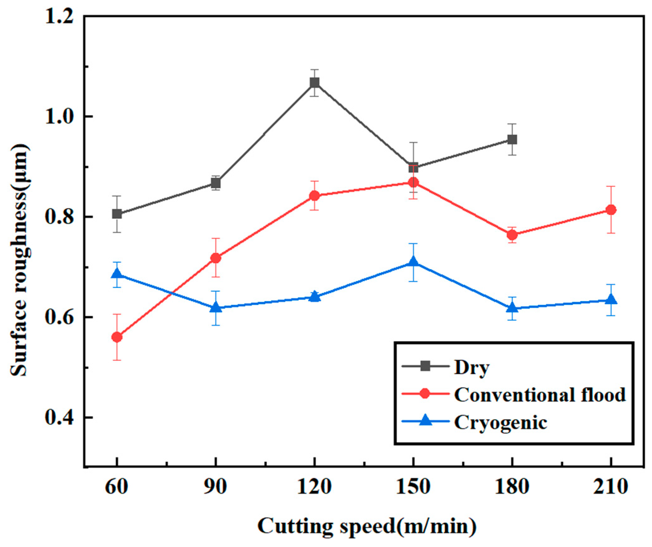
3.4. Surface Roughness
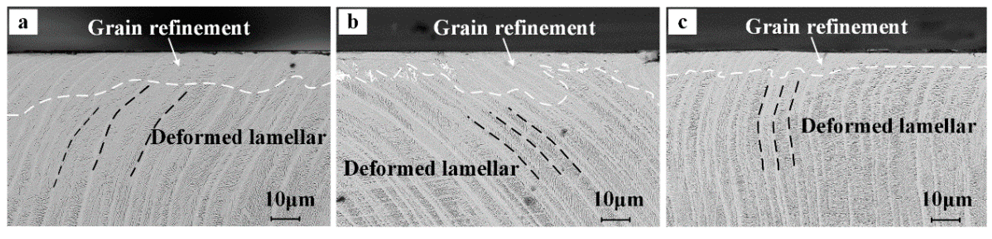
3.5. Microstructure Morphology of Sub-Surface
4. Conclusions
- (a)
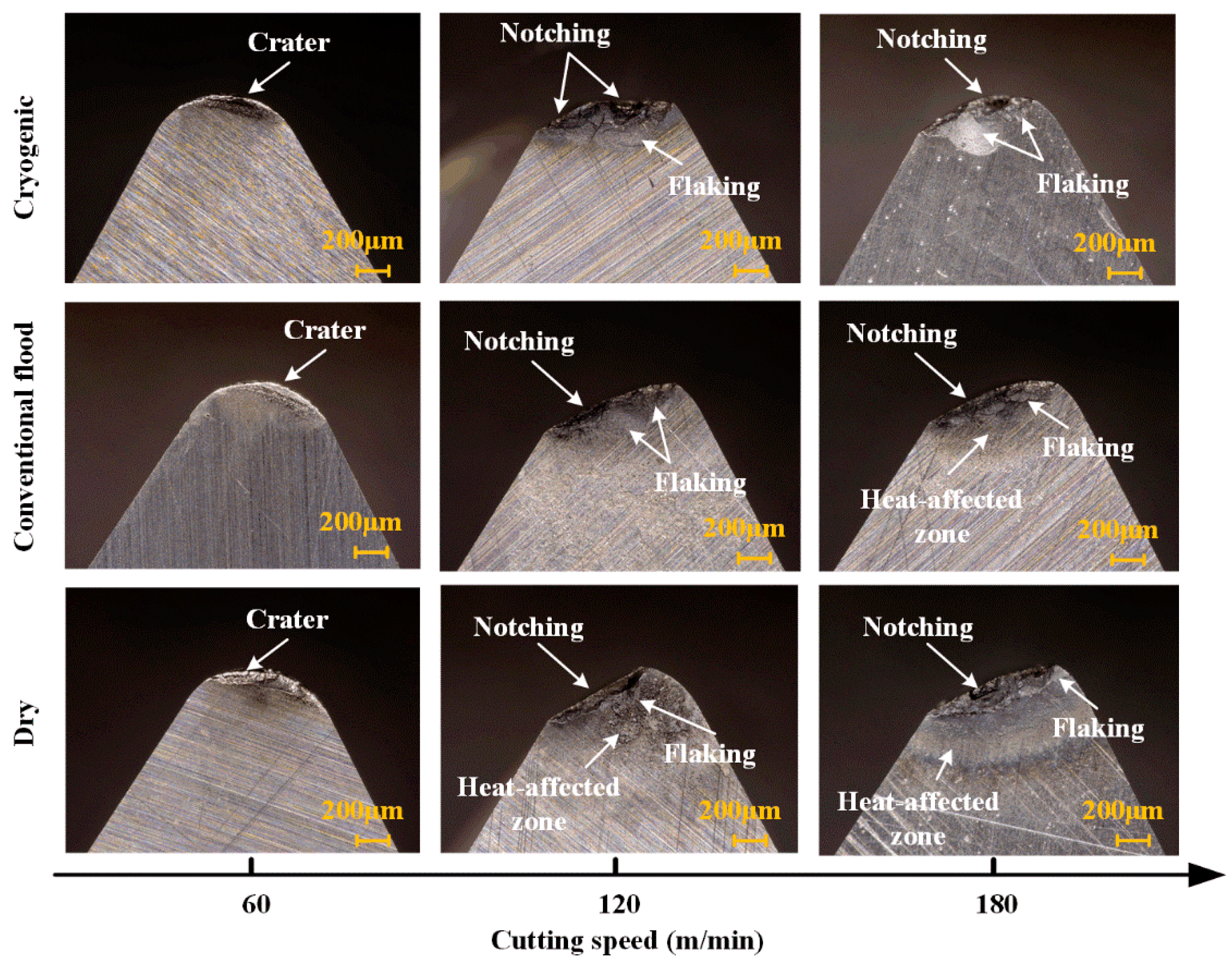
- The flank and rake face of the tool are worn to varying degrees at high-speed turning. The crater wear is observed on the rake face at vc = 60 m/min. With the increase in cutting speed, the crater wear is expanded, progressing into more serve flaking and notching wear. LN2-assisted cutting delays the occurrence of this state and greatly improves the tool life;
- (b)
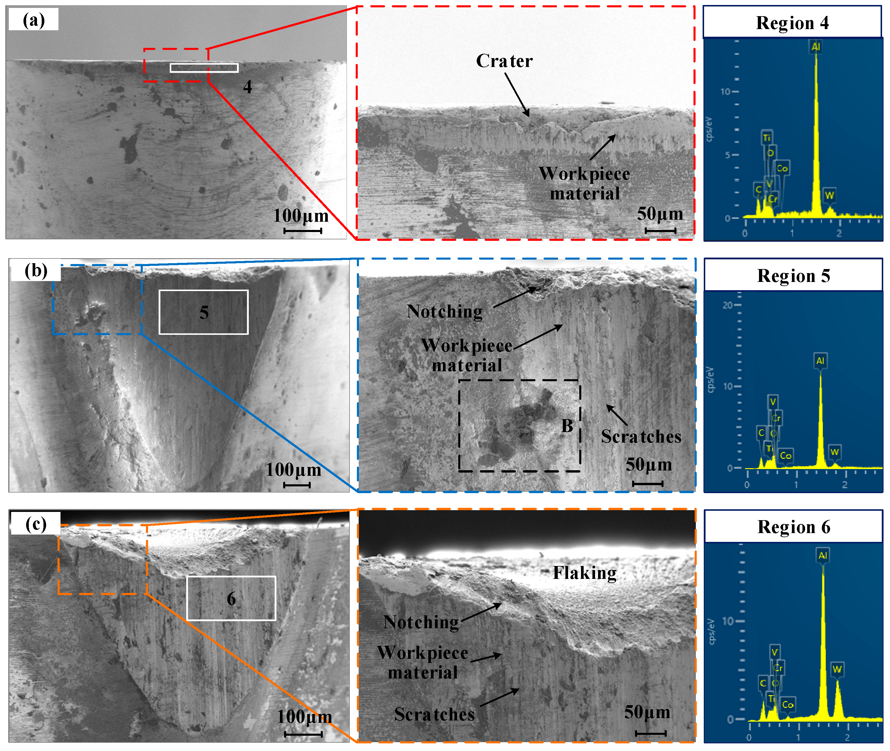
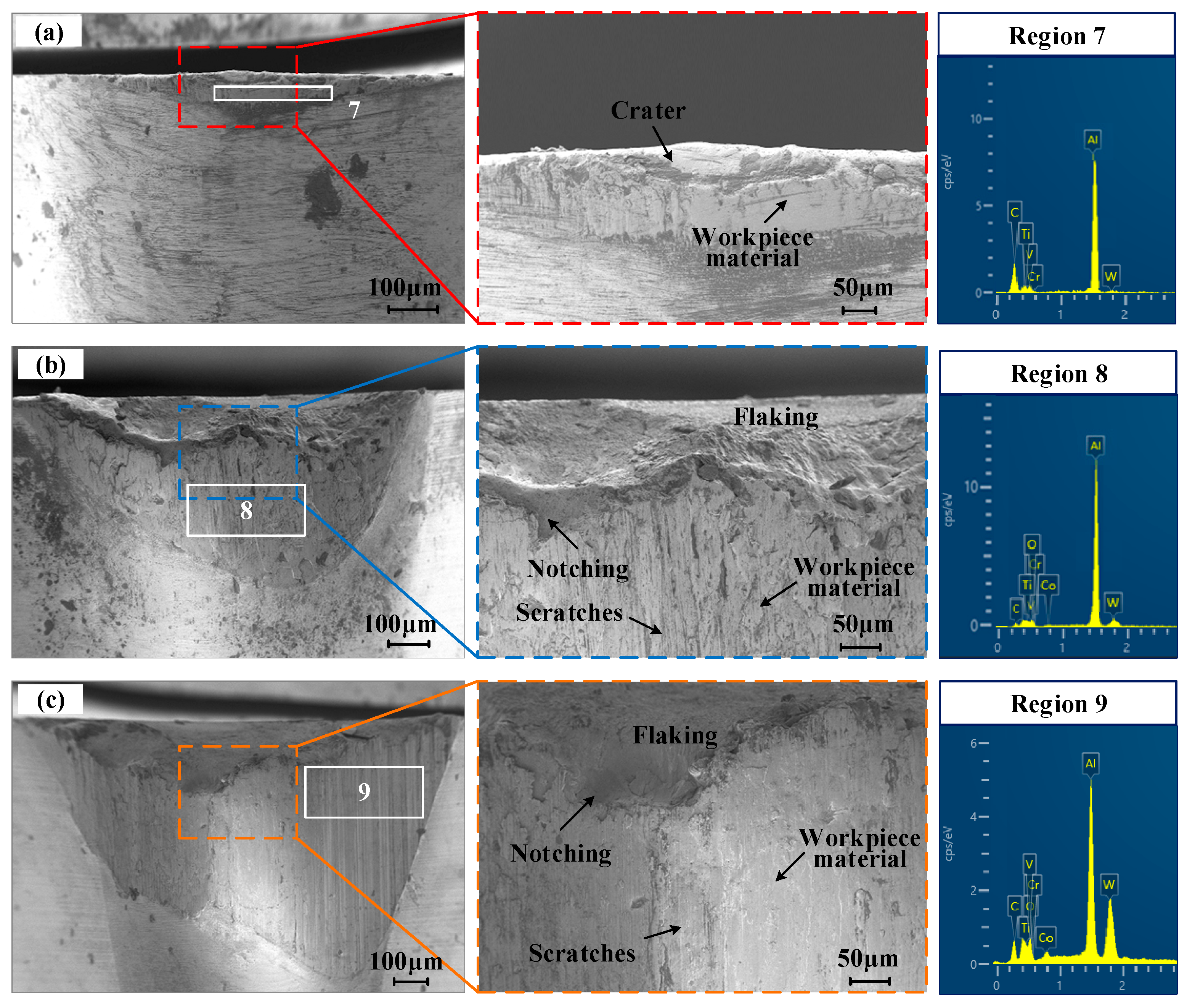
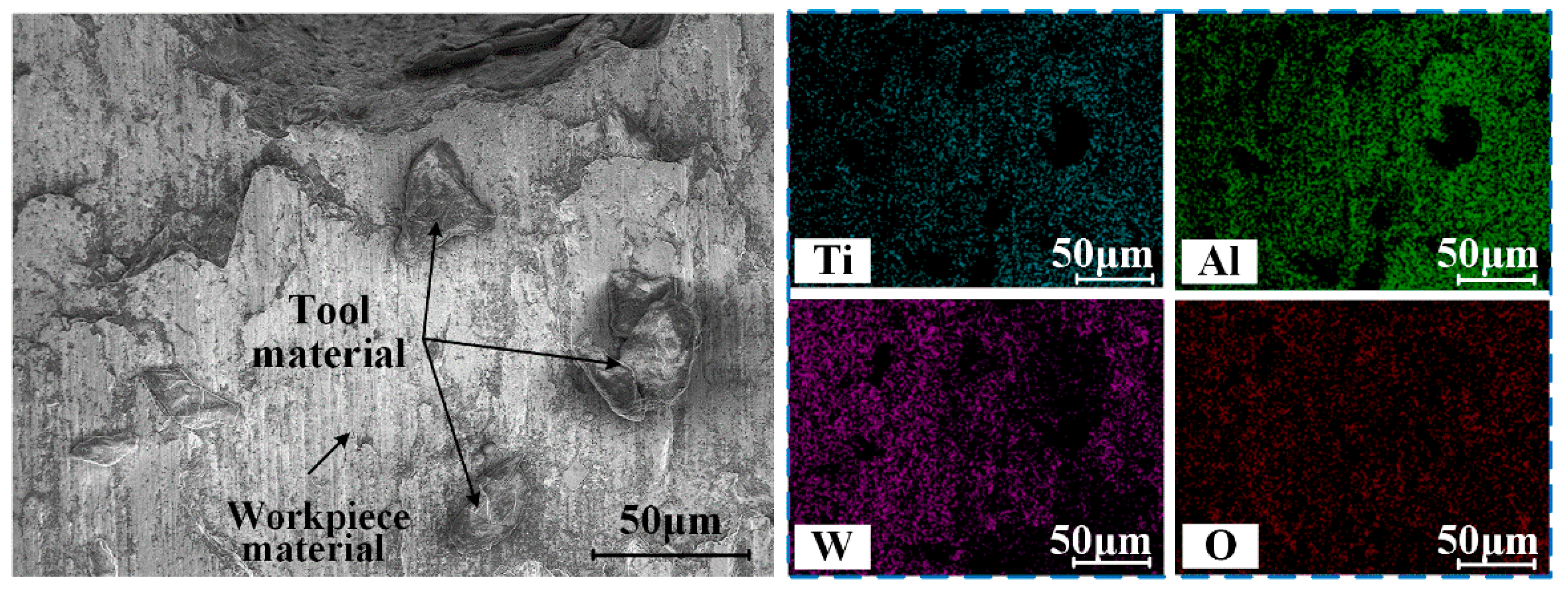
- The main wear pattern in dry machining is gradually transformed from adhesive wear to diffusion and oxidation wear at high speeds. The wear mechanism is still mainly adhesive wear in emulsion and LN2 cooling conditions, accompanied by slight diffusion and oxidation wear. Cryogenic cooling has a significant effect on inhibiting adhesion, diffusion, and oxidative wear;
- (c)
- Cryogenic cooling-assisted high-speed machining can significantly improve the surface finish and inhibit the deformation of the sub-surface microstructure. To some extent, the cooling effect of LN2 inhibits thermal activation and reduces the degree of grain refinement. However, the combination of cryogenic cooling and high-speed machining technology is a field worthy of exploration from a long-term perspective;
- (d)
- The curves of the Vmax, F, and Ra turn at vc = 120 m/min in dry conditions and at vc = 150 m/min in emulsion and LN2 conditions. It is preliminarily considered that the brittle–ductile transition of γ-TiAl alloy occurs within this cutting speed range. Further exploration is needed in future research work.
5. Prospect
Author Contributions
Funding
Conflicts of Interest
References
- Xu, R.; Li, M.; Zhao, Y. A review of microstructure control and mechanical performance optimization of γ-TiAl alloys. J. Alloys Compd. 2022, 932, 167611. [Google Scholar] [CrossRef]
- Castellanos, S.; Cavaleiro, A.J.; Jesus, A.D.; Neto, R.; Alves, J.L. Machinability of titanium aluminides: A review. Materials 2019, 233, 426–451. [Google Scholar] [CrossRef]
- Clemens, H.; Mayer, S. Design, processing, microstructure, properties, and applications of advanced intermetallic TiAl alloys. Adv. Eng. Mater. 2013, 15, 191–215. [Google Scholar] [CrossRef]
- Hood, R.; Aspinwall, D.K.; Voice, W. Creep feed grinding of γ-TiAl using single layer electroplated diamond super abrasive wheels. CIRP J. Manuf. Sci. Technol. 2015, 11, 36–44. [Google Scholar] [CrossRef]
- Yao, C.F.; Lin, J.N.; Wu, D.X.; Junxue, R.E. Surface integrity and fatigue behavior when turning γ-TiAl alloy with optimized PVD-coated carbide inserts. Chin. J. Aeronaut. 2018, 145, 214–224. [Google Scholar] [CrossRef]
- Priarone, P.C.; Robiglio, M.; Settineri, L.; Tebaldo, V. Milling and Turning of Titanium Aluminides by Using Minimum Quantity Lubrication. Procedia CIRP 2014, 24, 62–67. [Google Scholar] [CrossRef]
- Beranoagirre, A.; López de Lacalle, L.N. Optimizing the turning of titanium aluminide alloys. Adv. Mater. Res. 2012, 498, 189–194. [Google Scholar] [CrossRef]
- Beranoagirre, A.; López de Lacalle, L.N. Optimising the milling of titanium aluminide alloys. Int. J. Mechatron. Manuf. Syst. 2010, 3, 425–436. [Google Scholar] [CrossRef]
- Beranoagirre, A.; de Lacalle, L.N.L. Grinding of gamma TiAl intermetallic alloys. Procedia Eng. 2013, 63, 489–498. [Google Scholar] [CrossRef]
- Cheng, Y.; Yuan, Q.; Zhang, B.; Wang, Z. Study on turning force of γ-TiAl alloy. Int. J. Adv. Manuf. Technol. 2019, 105, 2393–2402. [Google Scholar] [CrossRef]
- Beranoagirre, A.; Olvera, D.; López de Lacalle, L.N. Milling of gamma titanium–aluminum alloys. Int. J. Adv. Manuf. Technol. 2012, 62, 83–88. [Google Scholar] [CrossRef]
- Wang, B.; Liu, Z.Q.; Su, G.S.; Song, Q.; Ai, X. Investigations of critical cutting speed and ductile-to-brittle transition mechanism for workpiece material in ultra-high speed machining. Int. J. Mech. Sci. 2015, 104, 44–59. [Google Scholar] [CrossRef]
- Aspinwall, D.K.; Mantle, A.L.; Chan, W.K.; Hood, R.; Soo, S.L. Cutting temperatures when ball nose end milling γ-TiAl intermetallic alloys. CIRP Ann.-Manuf. Technol. 2013, 62, 75–78. [Google Scholar] [CrossRef]
- Klocke, F.; Lung, D.; Arft, M.; Priarone, P.C.; Settineri, L. On high-speed turning of a third-generation gamma titanium aluminide. Int. J. Adv. Manuf. Technol. 2013, 65, 155–163. [Google Scholar] [CrossRef]
- Saketi, S.; Odelros, S.; Östby, J.; Olsson, M. Experimental Study of Wear Mechanisms of Cemented Carbide in the Turning of Ti6Al4V. Materials 2019, 12, 2822. [Google Scholar] [CrossRef] [PubMed]
- Rajashree, M.; Ramanuj, K.; Amlana, P.; Kumar, S.A. Current Status of Hard Turning in Manufacturing: Aspects of Cooling Strategy and Sustainability. Lubricants 2023, 11, 108. [Google Scholar]
- Zou, L.; Huang, Y.; Zhang, G.J.; Cui, X. Feasibility study of a flexible grinding method for precision machining of the TiAl-based alloy. Mater. Manuf. Process. 2019, 34, 1160–1168. [Google Scholar] [CrossRef]
- Wang, Z.H.; Liu, Y.W. Study of surface integrity of milled gamma titanium aluminide. J. Manuf. Process. 2020, 56, 806–819. [Google Scholar] [CrossRef]
- Ezugwu, E.O. High speed machining of aero-engine alloys. J. Braz. Soc. Mech. Sci. Eng. 2004, 26, 1–11. [Google Scholar] [CrossRef]
- Liu, Z.; An, Q.; Xu, J.; Chen, M.; Han, S. Wear performance of (nc-AlTiN)/(a-Si3N4) coating and (nc-AlCrN)/(a-Si3N4) coating inhigh-speed machining of titanium alloys under dry and minimum quantity lubrication (MQL) conditions. Wear 2013, 305, 249–259. [Google Scholar] [CrossRef]
- Klocke, F.; Settineri, L.; Lung, D.; Claudio Priarone, P.; Arft, M. High performance cutting of gamma titanium aluminides: Influence of lubricoolant strategy on tool wear and surface integrity. Wear 2013, 302, 1136–1144. [Google Scholar] [CrossRef]
- González, H.; Pereira, O.; López de Lacalle, L.N.; Calleja, A.; Ayesta, I.; Muñoa, J. Flank-milling of integral blade rotors made in Ti6Al4V using Cryo CO2 and minimum quantity lubrication. J. Manuf. Sci. Eng. 2021, 143, 091011. [Google Scholar] [CrossRef]
- Khanna, N.; Shah, P.; de Lacalle, L.N.L.; Rodríguez, A.; Pereira, O. In pursuit of sustainable cutting fluid strategy for machining Ti-6Al-4V using life cycle analysis. Sustain. Mater. Technol. 2021, 29, e00301. [Google Scholar] [CrossRef]
- M’Saoubi, R.; Axinte, D.; Soo, S.L.; Nobel, C.; Attia, H.; Kappmeyer, G.; Engin, S.; Sim, W.-M. High performance cutting of advanced aerospace alloys and composite materials. CIRP Ann.-Manuf. Technol. 2015, 64, 557–580. [Google Scholar] [CrossRef]
- Devaraya, R.G.; Raviraj, S.; Rao, S.S.; Gaitonde, V.N. Analysis of Surface Roughness and Hardness in Titanium Alloy Machining with Polycrystalline Diamond Tool under Different Lubricating Modes. Mater. Res. 2014, 17, 1010–1022. [Google Scholar]
- Jawahir, I.S.; Attia, H.; Biermann, D.; Duflou, J.; Klocke, F.; Meyer, D.; Newman, S.T.; Pusavec, F.; Putz, M.; Rech, J.; et al. Cryogenic manufacturing processes. CIRP Ann.-Manuf. Technol. 2016, 65, 713–736. [Google Scholar] [CrossRef]
- Pratham, S.; Rohit, N.; Ramanuj, K.; Deepak, S.; Amlana, P.; Kumar, S.A.; Diptikanta, D. Cryogenics as a Cleaner Cooling Strategy for Machining Applications: A Concise Review. Int. J. Energy A Clean Environ. 2022, 23, 129–141. [Google Scholar]
- Navneet, K.; Chetan, A.; Yu, P.D.; Kumar, S.A.; Rocha, M.A.; Ribeiro, S.L.R.; Kumar, G.M.; Murat, S.; Grzegorz, M.K. Review on design and development of cryogenic machining setups for heat resistant alloys and composites. J. Manuf. Process. 2021, 68, 398–422. [Google Scholar]
- Shah, P.; Khanna, N.; Chetan. Comprehensive Machining Analysis to Establish Cryogenic LN2 and LCO2 as Sustainable Cooling and Lubrication Techniques. Tribol. Int. 2020, 148, 106314. [Google Scholar] [CrossRef]
- Musfirah, A.H.; Ghani, J.A.; Haron, C. Tool wear and surface integrity of Inconel 718 in dry and cryogenic coolant at high cutting speed. Wear 2017, 376–377, 125–133. [Google Scholar] [CrossRef]
- Yıldırım, C.V. Experimental comparison of the performance of nanofluids, cryogenic and hybrid cooling in turning of Inconel 625. Tribol. Int. 2019, 137, 366–378. [Google Scholar] [CrossRef]
- Shokrani, A.; Dhokia, V.; Newman, S.T. Investigation of the effects of cryogenic machining on surface integrity in CNC end milling of Ti-6Al-4V titanium alloy. J. Manuf. Process. 2016, 21, 172–179. [Google Scholar] [CrossRef]
- Sartori, S.; Ghiotti, A.; Bruschi, S. Hybrid lubricating/cooling strategies to reduce the tool wear in finishing turning of difficult-to-cut alloys. Wear 2017, 376–377, 107–114. [Google Scholar] [CrossRef]
- Zhao, W.; Ren, F.; Iqbal, A.; Gong, L.; He, N.; Xu, Q. Effect of liquid nitrogen cooling on surface integrity in cryogenic milling of Ti-6Al-4V titanium alloy. Int. J. Adv. Manuf. Technol. 2020, 106, 1497–1508. [Google Scholar] [CrossRef]
- Fernández, D.; Sandá, A.; Bengoetxea, I. Cryogenic Milling: Study of the Effect of CO2 Cooling on Tool Wear When Machining Inconel 718, Grade EA1N Steel and Gamma TiAl. Lubricants 2019, 7, 10. [Google Scholar] [CrossRef]
- Pereira, O.; Urbikain, G.; Rodríguez, A.; Fernández-Valdivielso, A.; Calleja, A.; Ayesta, I.; de Lacalle, L.L. Internal cryo lubrication approach for Inconel 718 milling. Procedia Manuf. 2017, 13, 89–93. [Google Scholar] [CrossRef]
- Priarone, P.C.; Klocke, F.; Faga, M.G.; Lung, D.; Settineri, L. Tool life and surface integrity when turning titanium aluminides with PCD tools under conventional wet cutting and cryogenic cooling. Int. J. Adv. Manuf. Technol. 2016, 85, 807–816. [Google Scholar] [CrossRef]
- Yuan, Q.; Cheng, Y.; Wang, Z.H.; Hu, X. Failure study of carbide tools for turning γ-TiAl alloys. Tool Eng. 2019, 53, 12–16. [Google Scholar]
- Astakhov, V. Tribology of Metal Cutting; Elsevier: Amsterdam, The Netherlands, 2006. [Google Scholar]
- Jiang, Z.H.; Wang, L.L.; Shi, L. Study on Tool Wear Mechanism and Characteristics of Carbide Tools in Cutting Ti6Al4V. J. Mech. Eng. 2014, 50, 178–184. [Google Scholar] [CrossRef]
- Tian, S.; Qi, W.; Yu, H.; Sun, H.; Li, Q. Microstructure and creep behaviors of a high Nb-TiAl intermetallic compound based alloy. Mater. Sci. Eng. A 2014, 614, 338–346. [Google Scholar] [CrossRef]
- Wang, Q.; Chen, R.; Gong, X.; Guo, J.; Su, Y.; Ding, H.; Fu, H. Microstructure, Mechanical Properties, and Crack Propagation Behavior in High-Nb TiAl Alloys by Directional Solidification. Metall. Mater. Trans. A 2018, 49, 4555–4564. [Google Scholar] [CrossRef]
- Wang, Q.; Chen, R.; Chen, D.; Su, Y.; Ding, H.; Guo, J.; Fu, H. The characteristics and mechanisms of creep brittle-ductile transition in TiAl alloys. Mater. Sci. Eng. 2019, 767, 138393. [Google Scholar] [CrossRef]
- Wei, W.; Zeng, W.; Chen, X.; Liang, X.; Zhang, J. Microstructural evolution, creep, and tensile behavior of a Ti-22Al-25Nb (at%) orthorhombic alloy. Mater. Sci. Eng. A 2014, 603, 176–184. [Google Scholar]
- Patriarca, L.; Içöz, C.; Filippini, M.; Beretta, S. Microscopic Analysis of Fatigue Damage Accumulation in TiAl Intermetallics. Key Eng. Mater. 2014, 592–593, 30–35. [Google Scholar]


| Properties | Temperature (°C) | |
|---|---|---|
| 25 | 800 | |
| Elastic modulus (GPa) | 172 | 151 |
| Tensile strength (GPa) | 540 | 500 |
| Yield strength (MPa) | 440 | 380 |
| Thermal conductivity (W/m·k) | 18.6 | 23.1 |
| Ductility (%) | 1.5 | 6 |
| Item | Value |
|---|---|
| Cooling media | Dry, Emulsion, LN2 |
| Cutting speed (vc) | 60, 90, 120, 150, 180, 210 m/min |
| Feed rate (f) | 0.1 mm/r |
| Cutting depth (ap) | 0.2 mm |
| Rake angle (γ) | 3° |
| Relief angle (α) | 8° |
| Cutting Speed | Element Composition (at%) | |||||||
|---|---|---|---|---|---|---|---|---|
| Ti | Al | V | Cr | W | C | Co | O | |
| 60 | 30.45 | 40.66 | 1.04 | 4.15 | 0.17 | 23.65 | - | - |
| 120 | 21.88 | 29.89 | 0.27 | 2.36 | 0.10 | 25.49 | 0.47 | 19.53 |
| 180 | 17.56 | 28.81 | 0.68 | 1.51 | 0.25 | 29.38 | 0.55 | 21.26 |
| Cutting Speed | Element Composition (at%) | |||||||
|---|---|---|---|---|---|---|---|---|
| Ti | Al | V | Cr | W | C | Co | O | |
| 60 | 30.23 | 34.31 | 1.67 | 1.44 | 0.04 | 32.31 | - | - |
| 120 | 17.79 | 30.97 | 0.98 | 1.40 | 0.21 | 32.52 | 0.13 | 15.99 |
| 180 | 19.51 | 23.63 | 0.80 | 0.57 | 0.31 | 34.87 | 0.50 | 19.81 |
| Cutting Speed | Element Composition (at%) | |||||||
|---|---|---|---|---|---|---|---|---|
| Ti | Al | V | Cr | W | C | Co | O | |
| 60 | 21.78 | 29.92 | 0.83 | 0.21 | 0.03 | 47.23 | - | - |
| 120 | 14.53 | 24.83 | 0.76 | 0.94 | 0.35 | 46.95 | 0.12 | 11.51 |
| 180 | 14.32 | 22.35 | 0.73 | 0.78 | 0.51 | 45.43 | 0.80 | 15.08 |
Disclaimer/Publisher’s Note: The statements, opinions and data contained in all publications are solely those of the individual author(s) and contributor(s) and not of MDPI and/or the editor(s). MDPI and/or the editor(s) disclaim responsibility for any injury to people or property resulting from any ideas, methods, instructions or products referred to in the content. |
© 2023 by the authors. Licensee MDPI, Basel, Switzerland. This article is an open access article distributed under the terms and conditions of the Creative Commons Attribution (CC BY) license (https://creativecommons.org/licenses/by/4.0/).
Share and Cite
Wang, X.; Zhang, X.; Pan, D.; Niu, J.; Fu, X.; Qiao, Y. Tool Wear and Surface Integrity of γ-TiAl Cryogenic Coolant Machining at Various Cutting Speed Levels. Lubricants 2023, 11, 238. https://doi.org/10.3390/lubricants11060238
Wang X, Zhang X, Pan D, Niu J, Fu X, Qiao Y. Tool Wear and Surface Integrity of γ-TiAl Cryogenic Coolant Machining at Various Cutting Speed Levels. Lubricants. 2023; 11(6):238. https://doi.org/10.3390/lubricants11060238
Chicago/Turabian StyleWang, Xiangyu, Xiaoxia Zhang, Duo Pan, Jintao Niu, Xiuli Fu, and Yang Qiao. 2023. "Tool Wear and Surface Integrity of γ-TiAl Cryogenic Coolant Machining at Various Cutting Speed Levels" Lubricants 11, no. 6: 238. https://doi.org/10.3390/lubricants11060238