Article

The Influences of Different Parameters on the Static and Dynamic Performances of the Aerostatic Bearing

1
AECC Hunan Aviation Powerplant Research Institute, Zhuzhou 412002, China
2
Army Aviation Institute, Beijing 101121, China
3
Department of Engineering Mechanics, Northwestern Polytechnical University, Xi’an 710072, China
*
Author to whom correspondence should be addressed.
Lubricants 2023, 11(3), 130; https://doi.org/10.3390/lubricants11030130
Submission received: 6 November 2022 / Revised: 7 February 2023 / Accepted: 10 February 2023 / Published: 13 March 2023

Abstract

:
Aerostatic bearings have been widely applied to high-rotating speed machines due to their low friction and high rotational speed advantages. The geometry parameters, supply pressure and rotational speed play important roles in the static and dynamic performances of the aerostatic bearings. In this paper, the steady state and dynamic Reynolds equations are solved by the finite difference method (FDM) and used to study the static and dynamic performances of the aerostatic bearings. Then, combined with the motion equation of the rigid rotor-aerostatic bearing system, the linear stability of the aerostatic bearing is also studied. Moreover, based on the theory mentioned above, the influences of the geometry parameters (such as orifice diameter, radial clearance and eccentricity), rotational speed and supply pressure are investigated in detail. It was found that aerostatic bearing geometries, rotational speed and supply pressure had a significant effect on the steady and dynamic performances. Under the low-speed conditions and high supple pressure, the static pressure effect plays the main role in the performances of the aerostatic bearings, while on the contrary, the rotational effect plays the main role. Furthermore, a half-speed whirl may generate under certain conditions. The results also provide useful design guidelines for aerostatic bearings in high-speed machines.

1. Introduction

With the merits of low noise, high precision, low friction, high rotational speed and long life, gas bearings have been widely applied in the high-precision and high-speed rotating machines, such as high-speed motors, ultra-precision machining spindles, precision guide rails and so on. Compared with traditional bearings like oil and ball bearings, gas bearings work with low heat generation, oil-free pollution and a simple auxiliary apparatus [1,2,3,4,5,6]. In order to overcome the poor load capacity of gas bearings due to the low viscosity, gas bearings with orifice restrictors, known as aerostatic bearings, use external high-pressure gas to generate extra load capacity. Like traditional oil bearings [7,8], water bearings [9,10] and squeeze film dampers [11,12], their static and dynamic characteristics are the key to their design and application, for which there exists numerous papers about the study of static and dynamic performances on them in the past. Similarly, in the application of the aerostatic bearings, the static and dynamic performance is also the key characteristic of the aerostatic bearings. In general, the static and dynamic characteristics contain the bearing capacity, static stiffness, dynamic stiffness and damping coefficient and linear stability. The static and dynamic characteristics of aerostatic bearings are affected by the geometry parameters and supply pressure of the aerostatic bearings and rotational speed, which leads to abundant literature on the characteristics of aerostatic bearings published in the past.
Cheng et al. [13] studied the effect of the number of orifices on the static performance of the aerostatic bearing and the results showed that the small number of feeding holes without locating the bearing bottom is suitable for a high-speed condition, while the large number of feeding holes is suitable for a low-speed condition. Ise et al. [14] researched the influence of the asymmetry supply pressure distribution of the upper and lower rows of orifices on the bearing capacity and mass flow of the aerostatic bearing. The results showed that this will lead to a larger bearing capacity with a decrease in the mass flow. The opening pressure-equalizing grooves were applied to improve the bearing capacity, while the effects of the parameters of the pressure-equalizing grooves on the bearing capacity and static stiffness were also studied [15]. Research showed that the opening pressure-equalizing grooves along the axis direction is more useful to the bearing capacity than the grooves along the circumferential direction. Su and Lie [16] investigated the rotational effect of the aerostatic bearing with orifices and a porous restrictor. The results showed that an aerostatic bearing with five rows of orifice feedings could match the porous air bearings in some certain characteristics, while the aerostatic bearings with orifices had less mass flow consumption. Moreover, the L/D (the ratio of bearing length to diameter) can be strengthened as the rotational effect. The influence of the orifice number and distribution on the static and dynamic performance was studied by Yang et al. [17] and the proper orifice distribution can eliminate the orifice backflow phenomenon. Wang et al. [18] studied the rotational effect on the static characteristics of a pure dynamic bearing, a pure aerostatic bearing and a hybrid gas bearing in detail. Moreover, they [19] also studied the effect of surface waviness along the axis and circumferential direction on the aerostatic bearings and the results showed that the bearing capacity, static stiffness and mass flow increased and the friction decreased with the increasing wave’s amplitude.
As mentioned above, the static characteristics of the aerostatic bearings were studied by solving the steady state Reynolds equation, which ignores the squeezing effect. However, the gas film of aerostatic bearings is not only used for supporting and reducing friction and wear, but is also a key point of the bearing rotor system from the viewpoint of bearing rotordynamics. The performance of the gas film has an important effect on the dynamic performance of the gas-bearing rotor system. Therefore, the dynamic characteristics of the aerostatic bearings are also the key characteristic of the aerostatic bearings. Moreover, due to the compressibility and low viscosity of the gas, the aerostatic bearings tend to generate whirl instability under high rotational speed. Therefore, the linear stability of the aerostatic bearings is also an important property for the aerostatic bearings’ application in high rotational speed machines.
Lund [20] adopted the linear Ph method to study whirl instability by the finite difference method (FDM), while Wadhwa et al. [21] also used the linear Ph method to investigated the effect of the rotational speed and geometry parameters on the dynamic stiffness, damping coefficient and the linear stability containing the critical rotational speed and mass. Han et al. [22] solved the dynamic Reynolds equation to obtain the dynamic stiffness and damping coefficients and then combined the rotor motion equation to obtain the orbit of the shaft center. The orbit of the shaft center obtained by numerical calculation was compared to the experimental results, which verified the correctness of the numerical calculation. Based on the research shown in reference [16], the stability of the aerostatic bearings with five rows of orifices and a porous restrictor was compared [23]. The whirl ratio was introduced into the study of dynamic stiffness and damping coefficients in references [17,24,25]. Chen et al. [24] found that static pressure effect plays the main role in the stability of the aerostatic bearing under the low rotational speed, while the rotational effect plays the main role in the stability under high speed. Moreover, the effect of different type of the orifice (i.e., inherent and simple orifice) on the stability was compared and the stability of the aerostatic bearing with an inherent orifice was better than the aerostatic bearing with a simple orifice under the same condition. Based on the gas flow state in the orifice by description of the Hagen–Poiseuille theory, a new Reynolds equation of aerostatic bearings was proposed to compute the dynamic coefficients. The stability threshold of the aerostatic bearing-rotor system was investigated based on the modified Reynolds equation mentioned above. In the paper [17,20,21,22,23,24,25,26], the approach to obtain the dynamic coefficient is the same as Lund’s [20] and the squeezing effect is not involved in the Reynolds equation directly in this study. By solving the transient Reynolds equation and motion equation of the rigid rotor, the stability of the aerostatic bearing with a single row and two rows of orifices was studied contrastively [27].The results showed that the stability of the aerostatic bearing with two rows of orifices is better than the aerostatic bearing with a single row of orifices. Otsu et al. [28] considered the inertial effect of gas and investigated the stability of rigid rotor-aerostatic bearings with compound orifices and inherent orifices numerically and experimentally. The results presented that the compound orifices can improve the stability of the aerostatic bearing compared with the inherent orifices. Based the transfer function, Belforte et al. [29] proposed a new method to obtain the dynamic coefficients of a dynamic gas bearing analytically. Then, the method was used to obtain the dynamic coefficients of an aerostatic bearing [30]. Based on the study of the effect of surface waviness on the static performance of the aerostatic [19], Wang et al. [31] investigated the influence of surface waviness along the axis and circumferential direction on the dynamic coefficients of aerostatic bearings. In the same way, the effects of the waviness’s amplitude and length on the dynamic coefficients were also studied. The research presented that the surface waviness has an obvious effect on the dynamic performance of aerostatic bearings. In addition, increasing the waviness’s amplitude increases the dynamic coefficients.
To sum up, there exist numerous papers about the study of the static and dynamic performances of the aerostatic bearings. However, in this paper, the study of the static and dynamic performances of the aerostatic bearings focuses on some parameters’ effects on the performances, which means that the study in this paper is detailed and comprehensive. In this paper, the steady and dynamic Reynolds equations for a linear aerostatic bearing-rotor system are solved to study the static performance, dynamic coefficients and linear stability. Moreover, the influences of the comprehensive parameters (such as eccentricity, rotational speed, gas film thickness, orifice diameter and supply pressure) on the static performance, dynamic coefficients and linear stability are also investigated in detail.

2. Mathematical Model

2.1. Reynolds Equation

The schematic diagram and coordinate axes of the aerostatic bearings are shown in Figure 1. There are two rows of inherent orifices, and each row contains eight feeding orifices distributed uniformly in the circumferential direction. In this paper, the Reynolds equation is used to calculate the gas pressure ( p ) distribution of the gas film. the Reynolds equation is shown in Equation (1) [3] and the gas film h can be calculated by Equation (2).
x ( p h 3 p x ) + z ( p h 3 p z ) = 6 η u ( p h ) x + 6 η w ( p h ) x + 12 η ( p h ) t 12 δ m ˙ p ρ d x d z
h = c + e cos ( φ φ 0 )
where c is clearance; e is eccentricity; ρ is the density of the gas; φ 0 is the attitude angle at the mid plane; z L / 2 is the axial distance from the mid plane; Z m is the mid plane; and
δ = { 1 , with   orifices 0 , without   orifices m ˙ = C d π d 0 h p s 2 ρ a p a ϕ ( p ) ϕ ( p ) = {   [ κ 2 ( 2 κ + 1 ) κ + 1 κ 1 ] 1 / 2 , p p s ( 2 κ + 1 ) κ κ 1 { κ κ 1 [ ( p p s ) 2 κ ( p p s ) κ + 1 κ ] } 1 / 2 , p p s > ( 2 κ + 1 ) κ κ 1
where δ is the Kronecker function; η is the dynamic viscosity of the gas; ρ a is the gas density under atmosphere pressure; u is the circumferential velocity of the journal; w is the axial velocity of the journal; C d is a discharge coefficient; κ is the heat capacity ratio; p a is the atmospheric pressure; p s is the supply pressure; and d 0 is the orifice diameter. When ignoring w , Equation (1) can be changed to Equation (3).
x ( p h 3 p x ) + z ( p h 3 p z ) = 6 η u ( p h ) x + 12 η ( p h ) t 12 δ m ˙ p ρ d x d z
With the dimensionless parameters shown as below:
p = p a P , h = c H , x = R φ , z = L Z , t = τ ω s , λ = ω s ω , Λ = 6 η ω R 2 p a c 2
(where ω s is the journal perturbation rotational speed; ω is the rotational speed of the journal; λ is the whirl ratio; and Λ is the bearing number), Equation (3) can be changed to Equation (4).
φ P H 3 P φ + ( R L ) 2 Z P H 3 P Z = Λ φ ( P H ) + 2 Λ λ τ ( P H ) + δ Q r
where Q r = 12 μ R c 3 L p a ρ a Δ φ Δ Z m ˙ = Γ s m ˙ .
According to paper [14], the perturbed film thickness is
H = H 0 + H X Δ X + H Y Δ Y
where H X = sin φ and H Y = cos φ . With the assumption that the X and Y components of the journal vibration are harmonic, the expression of the perturbed pressure is a complex form:
P = P 0 + P X Δ X + P Y Δ Y
where P 0 is the non-dimensional steady pressure and P X , P Y are the non-dimensional differential term of film pressure along the X and Y directions. The perturbed Q r is:
Q r = Q r 0 + Q r Y Δ Y + Q r X Δ X
where Q r Y and Q r X are listed in the Appendix A. Then, with Equations (5)–(7), Equation (4) can yield the following perturbed Reynolds equations, shown in Equations (8)–(10).
φ ( P 0 H 0 3 P 0 φ ) + ( R L ) 2 Z ( P 0 H 0 3 P 0 Z ) = Λ φ ( P 0 H 0 ) + δ Q r 0
φ ( P 0 H 0 3 P X φ + 3 P 0 H 0 2 H X P 0 φ + H 0 3 P X P 0 φ ) + ( R L ) 2 φ ( P 0 H 0 3 P X Z + 3 P 0 H 0 2 H X P 0 Z + H 0 3 P X P 0 Z ) = Λ φ ( P 0 H X + P X H 0 ) + 2 Λ λ i ( P 0 H X + P X H 0 ) + δ Q r X
φ ( P 0 H 0 3 P Y φ + 3 P 0 H 0 2 H Y P 0 φ + H 0 3 P Y P 0 φ ) + ( R L ) 2 φ ( P 0 H 0 3 P Y Z +   3 P 0 H 0 2 H Y P 0 Z + H 0 3 P Y P 0 Z ) = Λ φ ( P 0 H Y + P Y H 0 ) + 2 Λ λ i ( P 0 H Y + P Y H 0 ) + δ Q r Y
By adopting FDM, i.e., the finite difference method, Equations (8)–(10) can be changed into Equation (11) to Equation (13), and their computational domain is presented in Figure 2.
A 0 i , j P 0 i + 1 , j 2 + B 0 i , j P 0 i 1 , j 2 + C 0 i , j P 0 i , j + 1 2 + D 0 i , j P 0 i , j 1 2 E 0 i , j P 0 i , j 2 = Λ Δ φ ( P 0 i + 1 , j H 0 i + 1 , j P 0 i + 1 , j H 0 i 1 , j ) + ( Δ φ ) 2 Q r 0
A X i j P X i + 1 , j + B X i j P X i 1 , j + C X i j P X i , j + 1 + D X i j P X i , j 1 + E X i j P X i + 1 , j = F X i j
A Y i j P Y i + 1 , j + B Y i j P Y i 1 , j + C Y i j P Y i , j + 1 + D Y i j P Y i , j 1 + E Y i j P Y i + 1 , j = F Y i j

2.2. Static Characteristics

By solving Equation (11), the pressure distribution of the gas film is obtained and then the load capacity W X ,   W Y along the X and Y directions is acquired by Equation (14), while the total load capacity is calculated by Equation (15) [32].
{ W X = 0 L 0 2 π R ( p 0 p a ) sin φ d x d z W Y = 0 L 0 2 π R ( p 0 p a ) cos φ d x d z
W = W X 2 + W Y 2
As the load direction is the Y direction, W X = 0 and we can calculate the correction of the attitude angle Δ φ by Equation (16).
Δ φ = tan 1 ( W X W Y )
In the end, the attitude angle φ 0 can be calculated through the iterative procedure, i.e., φ n e w = φ o l d Δ φ until Δ φ = W X W Y 10 5 , which means the load direction is the Y direction. After obtaining the bearing capacity, the static stiffness is given as:
K w = d W d e Δ W Δ e = Δ W c Δ ε

2.3. Dynamic Coefficients

Based on the solution of the steady-state Reynolds equation, i.e., Equation (11), the eight dynamic coefficients can be calculated by the solutions of Equations (12) and (13) and the eight dynamic coefficients can be calculated as follows:
{ k x x = p a R L c 0 1 0 2 π R e ( P X ) sin ( φ ) d φ d Z k y x = p a R L c 0 1 0 2 π R e ( P X ) cos ( φ ) d φ d Z k y y = p a R L c 0 1 0 2 π R e ( P Y ) cos ( φ ) d φ d Z k x y = p a R L c 0 1 0 2 π R e ( P Y ) sin ( φ ) d φ d Z c x x = p a R L c ω 0 1 0 2 π I m ( P X ) sin ( φ ) d φ d Z c y x = p a R L c ω 0 1 0 2 π I m ( P X ) cos ( φ ) d φ d Z c y y = p a R L c ω 0 1 0 2 π I m ( P Y ) cos ( φ ) d φ d Z c x y = p a R L c ω 0 1 0 2 π I m ( P Y ) sin ( φ ) d φ d Z

2.4. Whirl Instability Analysis

The rigid rotor-aerostatic bearings are shown in Figure 3 and the two rotor ends are supported by aerostatic journal bearings, while the rotor mass is 2 m r and contains zero unbalanced mass. When the journal is disturbed by tiny dynamic excitations with whirl speed ω s , the gas film force Δ F X ,   Δ F Y can be written as Equation (19) and the motion equation is shown as Equation (20).
{ Δ F X = k x x Δ x + k x y Δ y + c x x Δ x ˙ + c x y Δ y ˙ Δ F Y = k y y Δ y + k y x Δ x + c y y Δ y ˙ + c y x Δ x ˙
{ m r x ¨ + Δ F X = 0 m r y ¨ + Δ F y = 0
Substituting Equation (21)
{ Δ x = x 0 e i ω s t Δ y = y 0 e i ω s t
where x 0 and y 0 are the constant, into Equation (20), Equation (22) can be obtained, where the k e q is inertial force and is equal to m r ω s 2 .
{ Δ F X = k e q x 0 e i ω s t Δ F Y = k e q y 0 e i ω s t
With Equations (19) and (21), Equation (22) can be rewritten as:
{ ( k x x k e q + i c x x ω s ) x 0 + ( k x y + i c x y ω s ) y 0 = 0 ( k y x + i c y x ω s ) x 0 + ( k y y k e q + i c y y ω s ) y 0 = 0
As x 0 0 ,   y 0 0 , Equation (24) can be obtained as follows and then rewritten as Equation (25).
| k x x k e q + i c x x ω s k x y + i c x y ω s k y x + i c y x ω s k y y k e q + i c y y ω s | = 0
{ ( k x x k e q ) ( k y y k e q ) k y x k x y c x x c y y ω s 2 + c y x c x y ω s 2 = 0 ( k x x k e q ) c y y ω s + ( k y y k e q ) c x x ω s ( k y x c x y ω s + k x y c y x ω s ) = 0
By adopting the dimensionless parameters:
K x x = c p a R L k x x ; K x y = c p a R L k x y ; K y x = c p a R L k y x ; K y y = c p a R L k y y C x x = c ω p a R L c x x ; C x y = c ω p a R L c x y ; C y x = c ω p a R L c y x ; C y y = c ω p a R L c y y M ¯ = m c ω 2 p a R L ; ( K e q ) c = ( M ¯ λ 2 ) c
Equation (25) can be rewritten as:
{ ( K x x K e q ) ( K y y K e q ) K y x K x y ( C x x C y y C y x C x y ) γ 2 = 0 ( K x x K e q ) C y y + ( K y y K e q ) C x x ( K y x C x y + K x y C y x ) = 0
In the end, we can obtain the critical whirl ratio λ c and critical non-dimensional inertial force ( K e q ) c by using Equation (27).
{ λ c 2 = ( K x x ( K e q ) c ) ( K y y ( K e q ) c ) K y x K x y C x x C y y C y x C x y ( K e q ) c = K y x C x y K x y C y x + K x x C y y + K y y C x x C x x + C y y

2.5. The Flow Chart of the Solution of the Reynolds Equations

As shown in Figure 4, with the calculation parameters (i.e., geometry parameters of bearing, supply pressure and rotation speed), the steady Reynolds equation (i.e., Equation (11)) is solved until there is convergence of the steady-state pressure and | W x / W y | 10 5 . Based on the solution of Equation (11), the dynamic Reynolds equation (i.e., Equations (12) and (13)) is solved until there is convergence of the perturbed pressure (i.e., P X and P Y ) with the initial whirl ratio λ . Then, the dynamic coefficients can by calculated by Equation (18) and the critical whirl ratio is obtained by Equation (27) with the dynamic coefficients until there is convergence of λ c and λ by the iteration solution of coupled Equations (12), (13) and (27). When the convergence of λ c and λ is verified, the stability thresholds of both the critical whirl ratio and the critical inertial force are obtained.

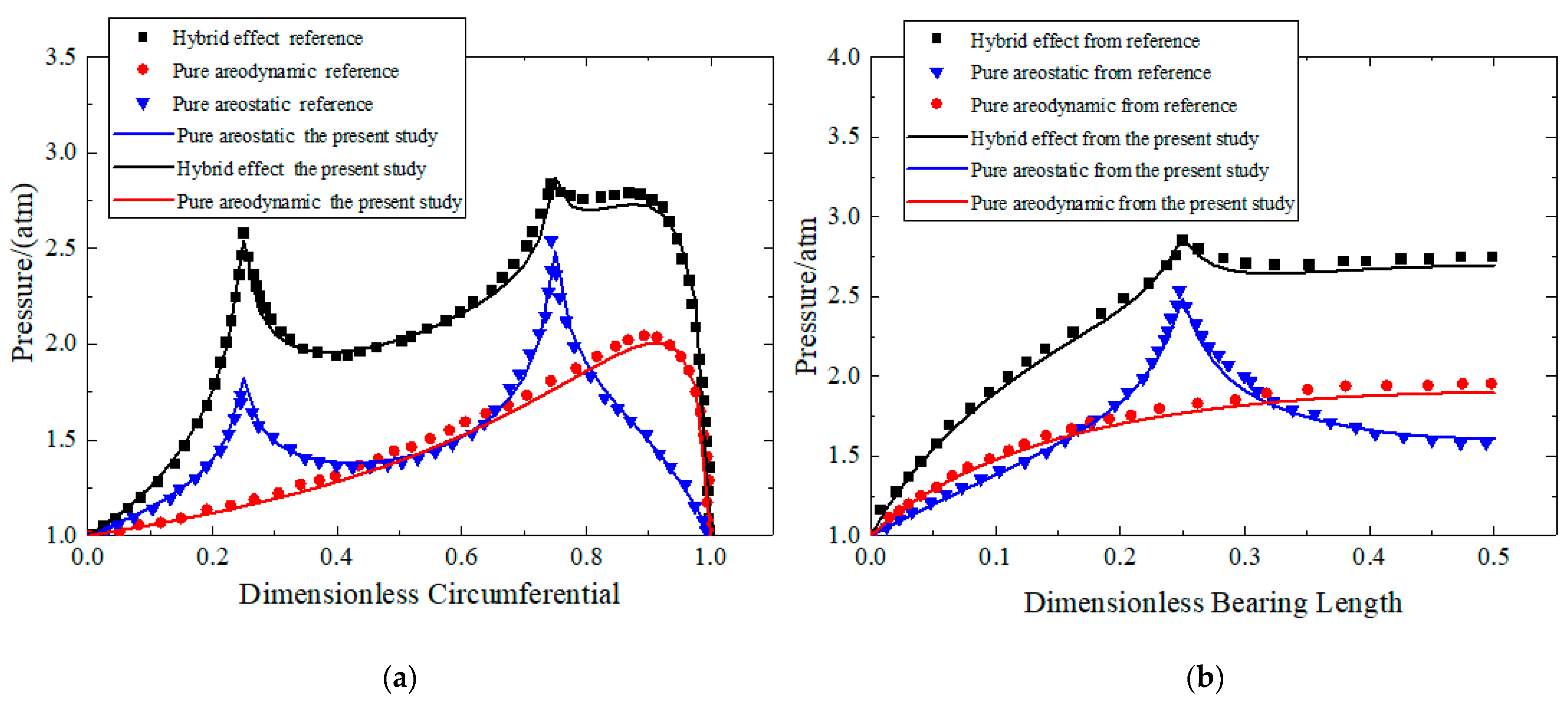
2.6. The Verification of the Solution for the Reynolds Equation

In order to verify the correctness of the numerical method, the results obtained from the present research were compared with the results from the paper [33]. The comparison of the calculation parameters are the same to the parameters in the paper [33]. The results calculated by the present study and published paper [33] are shown in Figure 5. As shown in the figure, the results from the present study show good agreement with the results from that of paper [33], which indicates the correctness of the calculation method in this paper. The load capacities with different mesh numbers of m and n are shown as follows. In order to select the appropriate number of grids, the load capacities with different mesh numbers of m and n are shown in Table 1. The aerostatic bearings’ parameters used in this section can be seen in the Table 2. The results show that when the number of grids increases to a certain value, the change of the bearing capacity is not obvious. In order to ensure calculation efficiency, the selected number of grids is m = 64 ,   n = 96 .

3. Results and Discussion

In this section, the influences of the different parameters (such as rotational speed, eccentricity, gas film thickness, orifice diameter and supply pressure) on the static performances are studied by solving the steady state Reynolds equation first. Then, the effects of the different parameters on the dynamic coefficients and stability are investigated by solving the dynamic Reynolds equation and rigid rotor motion equations in detail.

3.1. Static Performances

In this section, according to the Section 2 theory and method, the influences of different parameters on the static performances (such as bearing capacity, static stiffness, attitude angle and so on) are studied as follows. The aerostatic bearings’ parameters used in this section can be seen in Table 2.

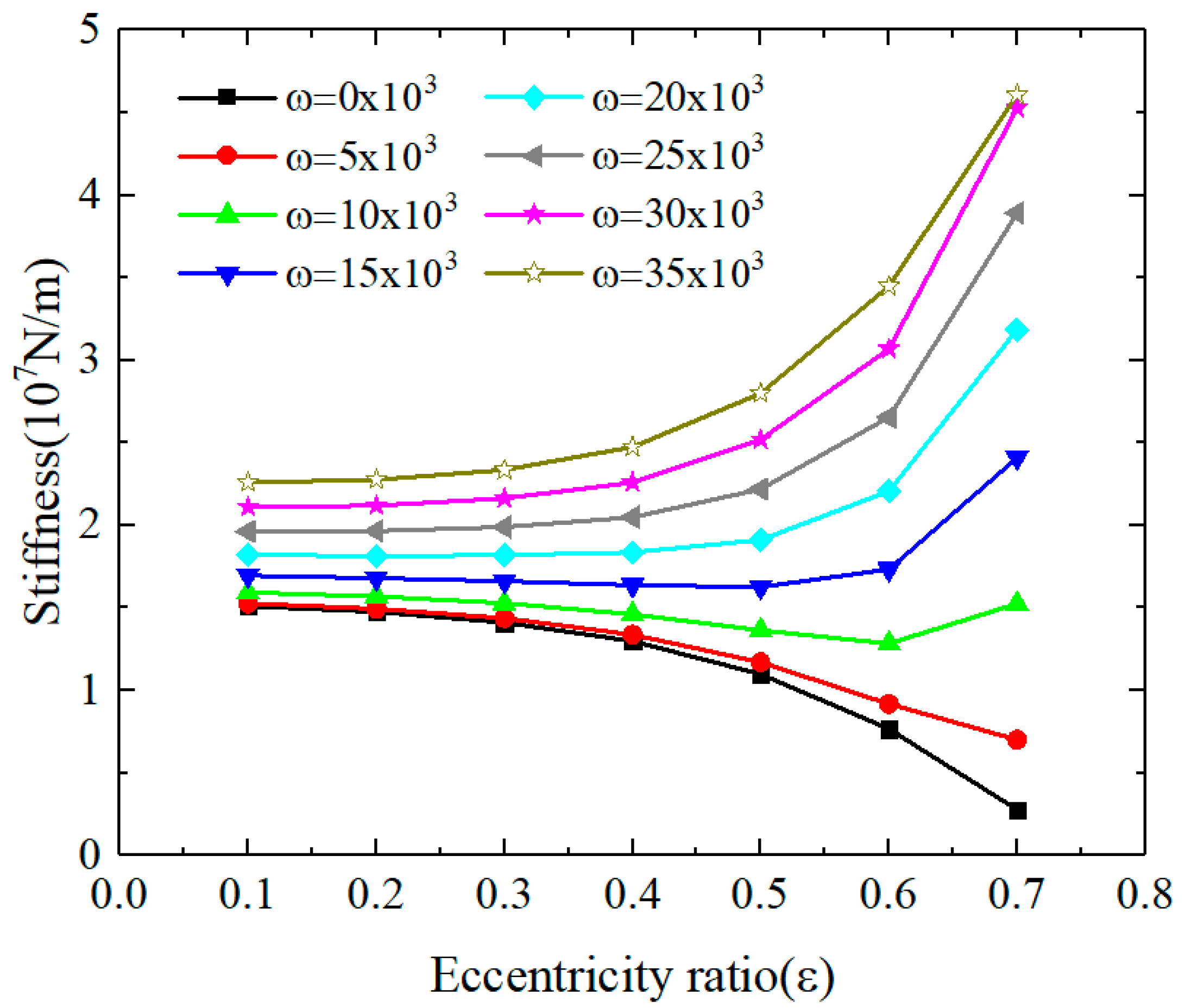
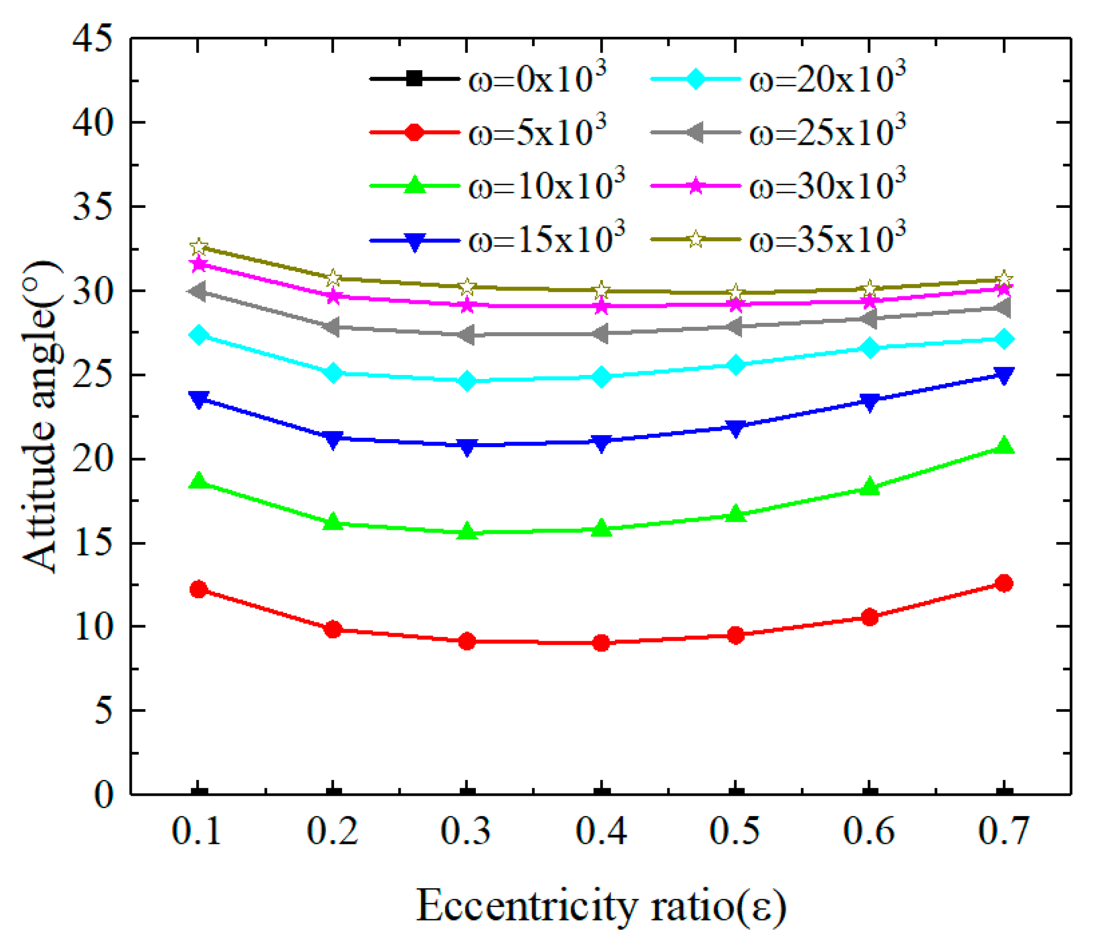
3.1.1. The Influences of Rotational Speed and Eccentricity

In this section, the reference parameters are d 0 = 0.2   m m ,   p s = 7   a t m ,   c = 15   μ m and the variable parameters are eccentricity and rotational speed. Figure 6, Figure 7 and Figure 8 describe the effects of the eccentricity and rotational speed on the bearing capacity, static stiffness and attitude angle. As shown in Figure 6, under a certain rotational speed, the bearing capacity increases with increasing eccentricity. The reason is as follows: with zero speed, the aerostatic bearing is under the pure static state and the gas film thickness of the upper half increases with an increase in the eccentricity, which leads to a decrease in the pressure of the orifice. On the contrary, the gas film thickness of the lower half decreases with the increasing eccentricity and the pressure of the orifice increases. The decreasing of the upper half and the increasing of the lower half results in the growth of the bearing capacity. When the rotational speed is not zero, the aerostatic bearing is under the hybrid state. With increasing eccentricity, on one hand, the gap of the pressure of the orifices at the upper and lower halves becomes larger; on the other hand, the rotational effect will be strengthened. This will increase the bearing capacity when the eccentricity increases. Moreover, under a certain the eccentricity, the bearing capacity increases with the increase of the speed, as the rotational effect is strengthened. When the eccentricity is larger, the rotational speed effect is more obvious.
As shown in Figure 7, the static stiffness decreases with the increasing eccentricity under the lower rotational speed (such as zero or 5000 rpm). According to Equation (17), the stiffness is the first derivative of the load capacity to eccentricity. As shown in Figure 6, under lower speed conditions, the slope of the load capacity decreases with an increase of ε for a certain speed. Therefore, as shown in Figure 7, under a lower speed condition, the stiffness decreases with an increase of ε for a certain speed. However, as shown in Figure 6, under hybrid conditions, the slope of the load capacity increases with an increase of ε for a certain speed. Therefore, under hybrid conditions, the stiffness increases with an increase of ε for a certain speed. Moreover, the static stiffness increases with the increasing rotational speed, which is caused by the strengthening rotational effect.
As shown in Figure 8, for a certain speed, the attitude angle decreases slightly and then increases with the increase of eccentricity. On the whole, the attitude angle does not change significantly with the eccentricity. Moreover, the attitude angle is almost zero under a pure-static condition, which meets the theory and verifies the correctness of the method in the paper. For certain eccentricity, the attitude angle increases with the increasing speed and the slope of the attitude angle decreases with the increasing speed.

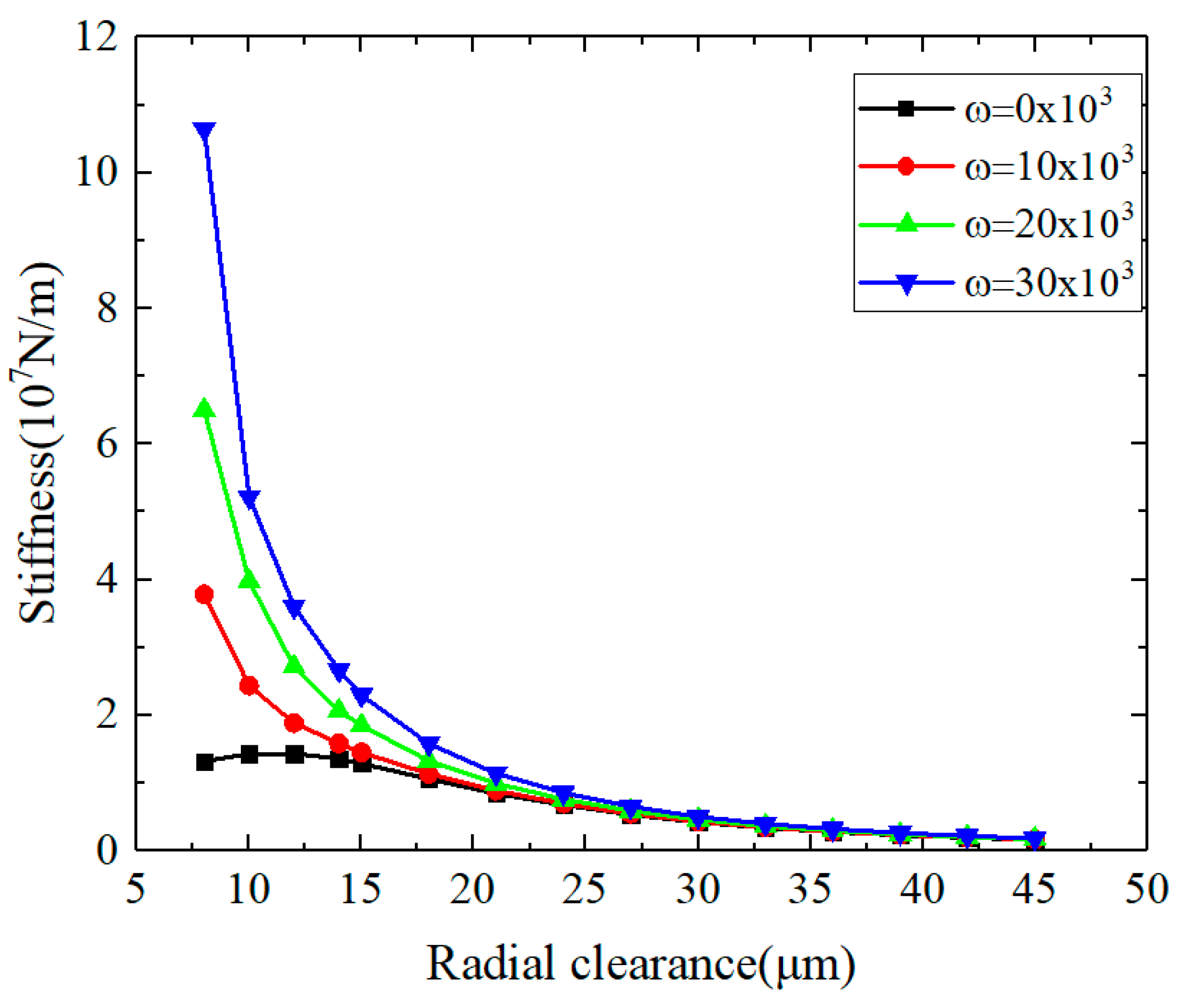
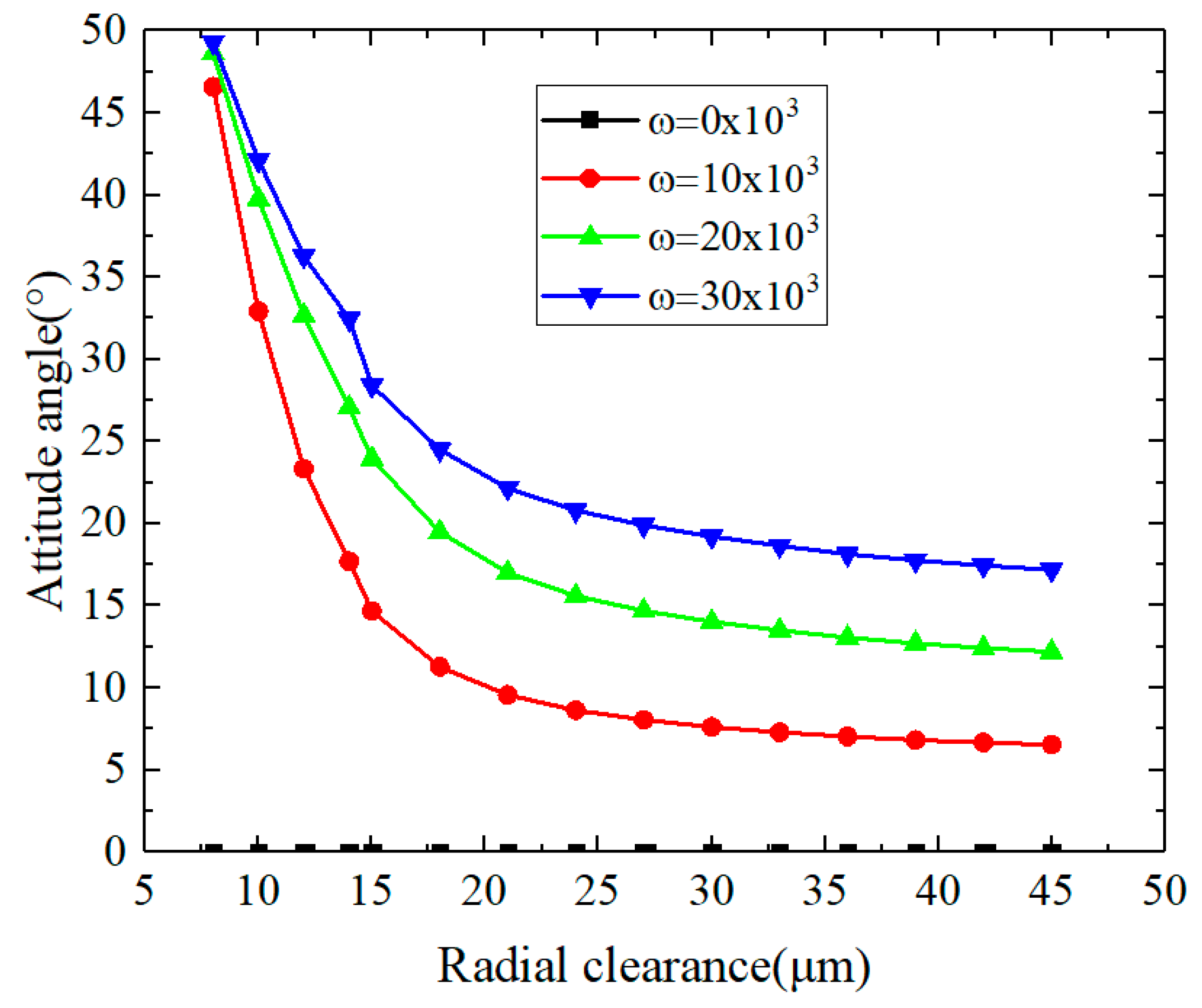
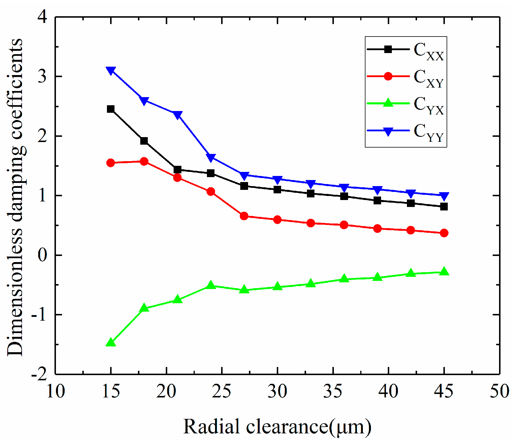
3.1.2. The Influences of Gas Film Radial Clearance

In this section, the reference parameters are d 0 = 0.2   m m ,   p s = 7   a t m ,   ε = 0.4 and the variable parameters are the radial clearance and rotational speed. Figure 9, Figure 10 and Figure 11 describe the effects of the radial clearance on the bearing capacity, static stiffness and attitude angle. As shown in Figure 9 and Figure 10, under the pure-static condition, the bearing capacity and stiffness increase and then decrease with the increase of the radial clearance, while the bearing capacity and stiffness decrease with the increase of the radial clearance under the higher speed. Under the pure-static condition, for a certain eccentricity, the pressure differential of the upper and lower halves of the aerostatic bearings increases with an increase of the radial clearance at the small radial clearance, which results in the increase of the bearing capacity. However, at the bigger radial clearance, the pressure differential of the upper and lower halves of the aerostatic bearings decreases with increase of the radial clearance, which results in the decrease of the bearing capacity. When the rotational speed is high, the aerostatic bearing is under the hybrid state and the bearing capacity is obviously affected by the rotational effect. Therefore, the rotational effect weakens with an increase of the radial clearance, which results in the decrease of the bearing capacity. Similarly, under the pure-static condition, the slope of the pressure differential of the upper and lower halves of the aerostatic bearings increases with an increase of the radial clearance at the small radial clearance, which results in the increase of the stiffness. However, at the bigger radial clearance, the slope of the pressure differential of the upper and lower halves of the aerostatic bearings decreases with an increase of the radial clearance, which results in the decrease of the stiffness. When the rotational speed is high, the rotational effect weakens with the increase of the radial clearance, which results in the decrease of the stiffness.
As shown in Figure 11, the attitude angle decreases with the increase of the radial clearance. When the radial clearance is small, the slope of the attitude angle is big with the change of the radial clearance. Conversely, the slope of attitude angle is small with the change of the radial clearance.

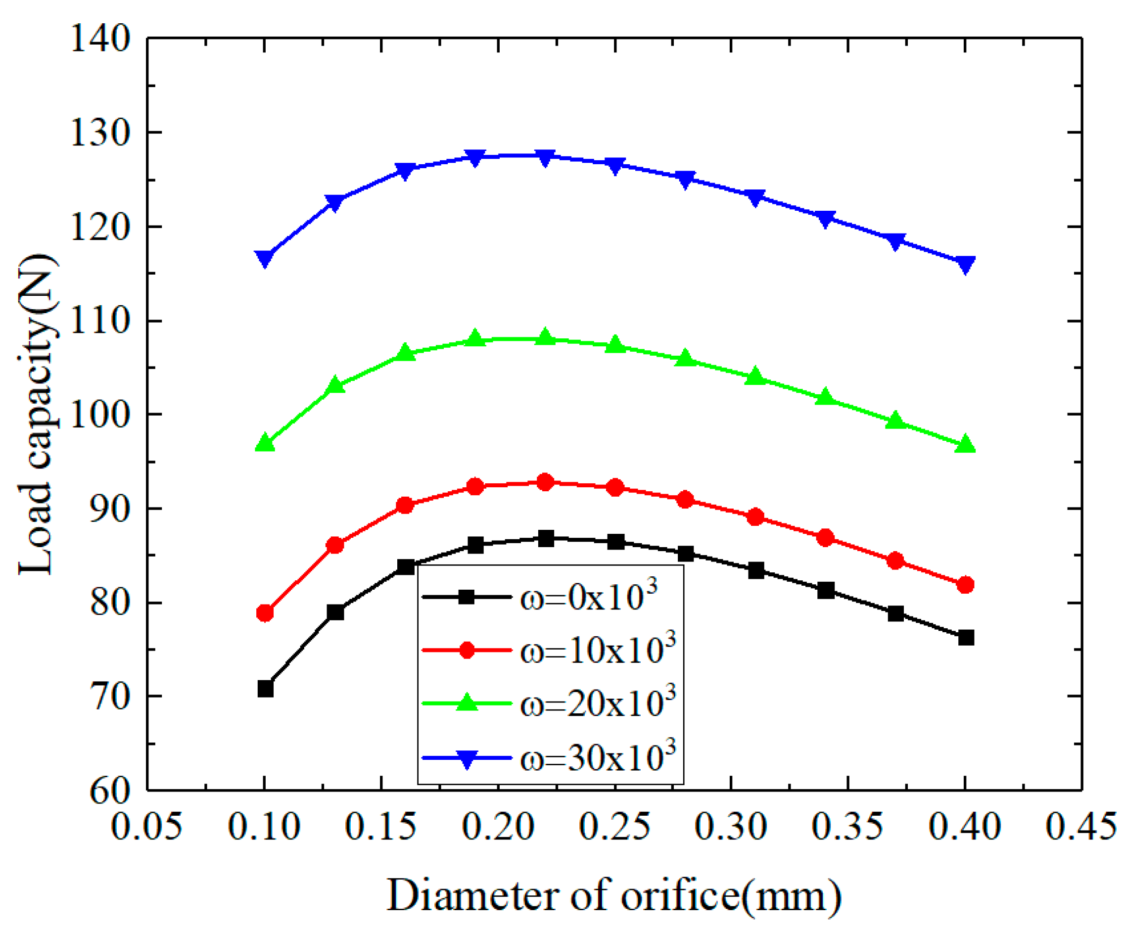
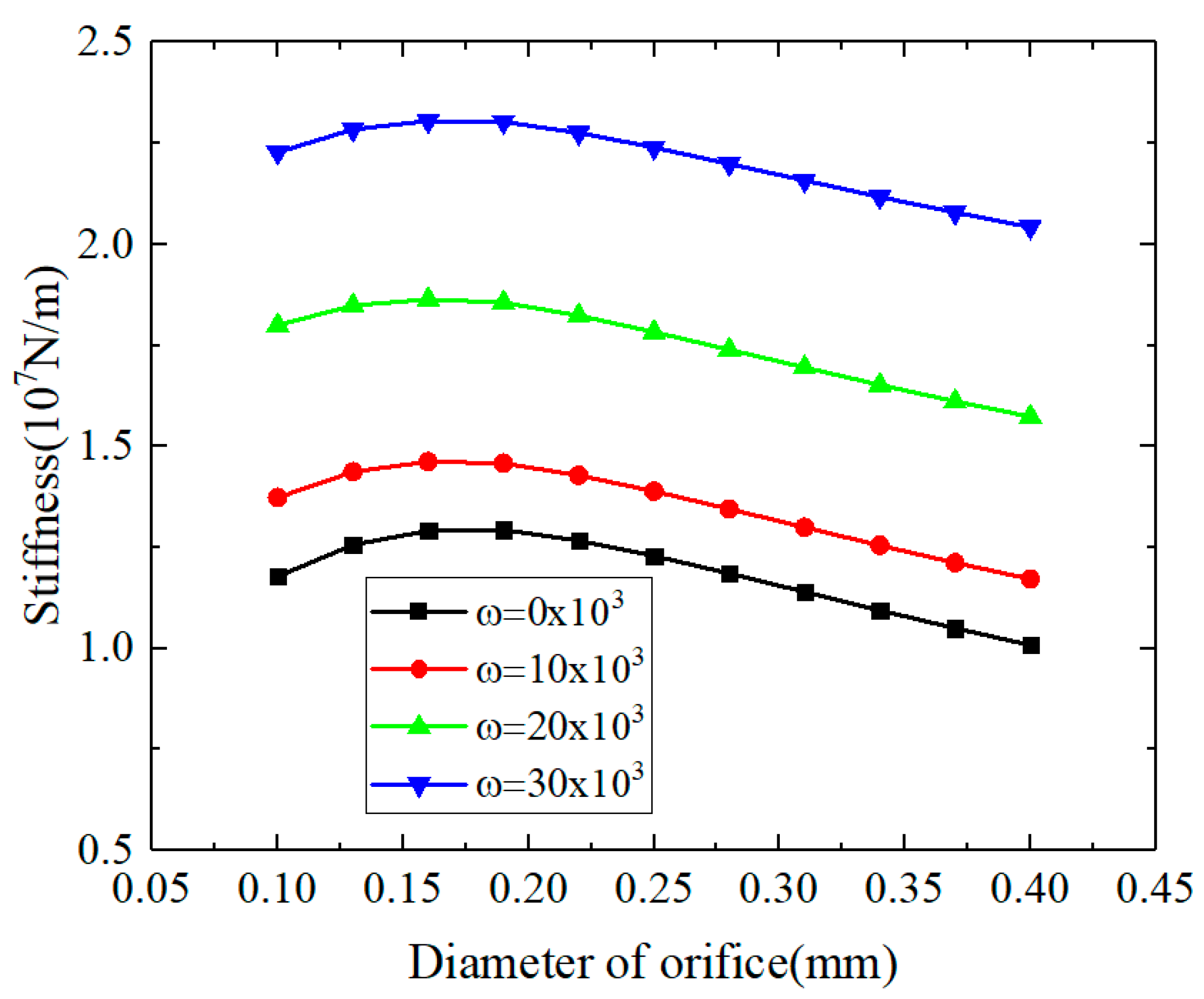
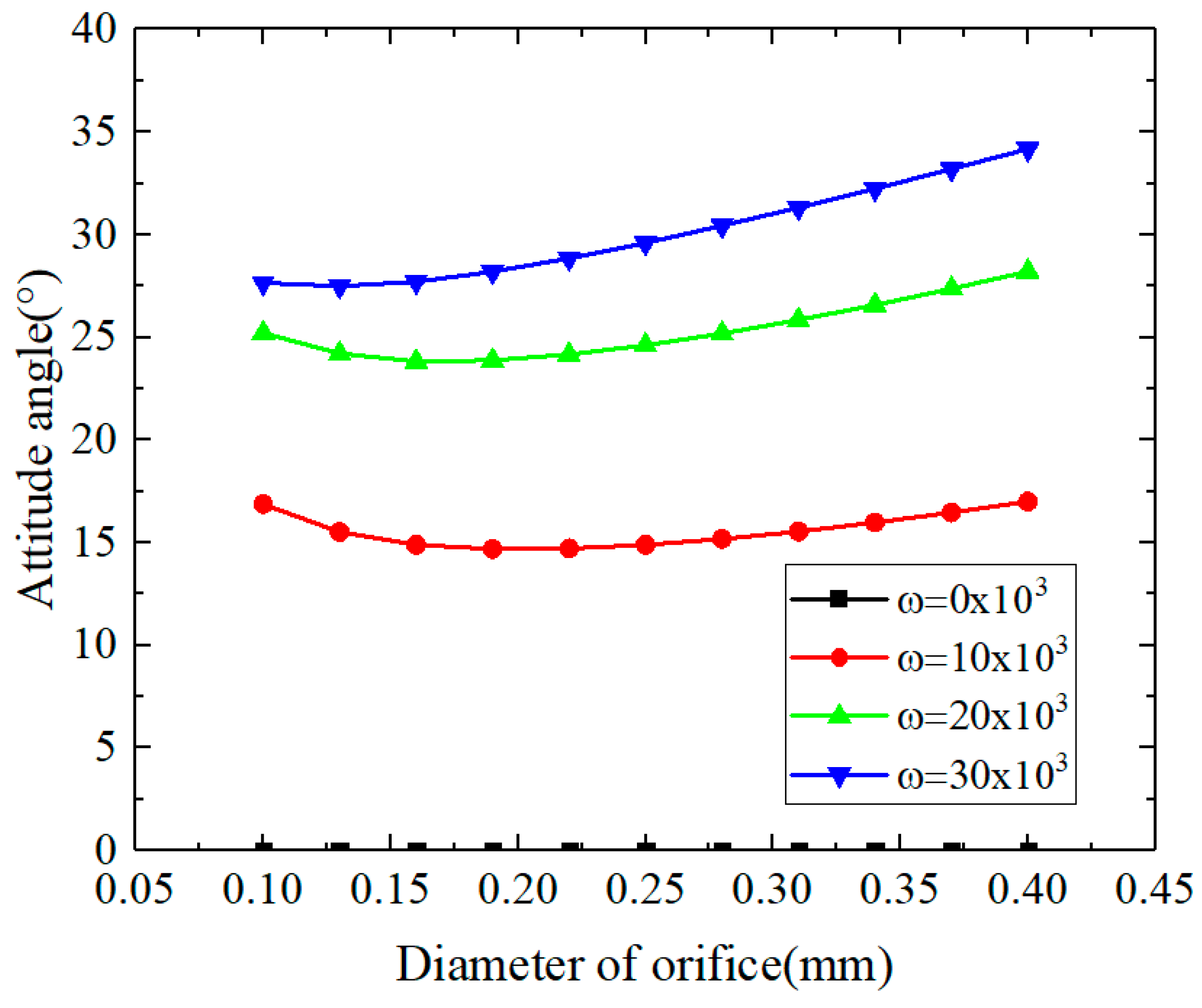
3.1.3. The Influences of Orifice Diameter

In this section, the reference parameters are c = 15   μ m ,   p s = 7   a t m ,   ε = 0.4 and the variable parameters are the orifice diameter and rotational speed. Figure 12, Figure 13 and Figure 14 give the effects of the orifice diameter on the bearing capacity, static stiffness and attitude angle. As shown in Figure 12 and Figure 13, whether the aerostatic bearing is under the pure-static or hybrid state, the bearing capacity and stiffness increase first and then decrease with the increase of the orifice diameter. This is combined with the effect of the radial clearance on the static performance in the last section. In the design of the aerostatic bearing, there exists an optimal value for the radial clearance and orifice diameter, which makes its static characteristics reach an optimal result. Moreover, as shown in Figure 14, under a high speed, the attitude angle increases with the increase of the orifice diameter, while the attitude angle decreases with the increase of the orifice diameter under low speed conditions.

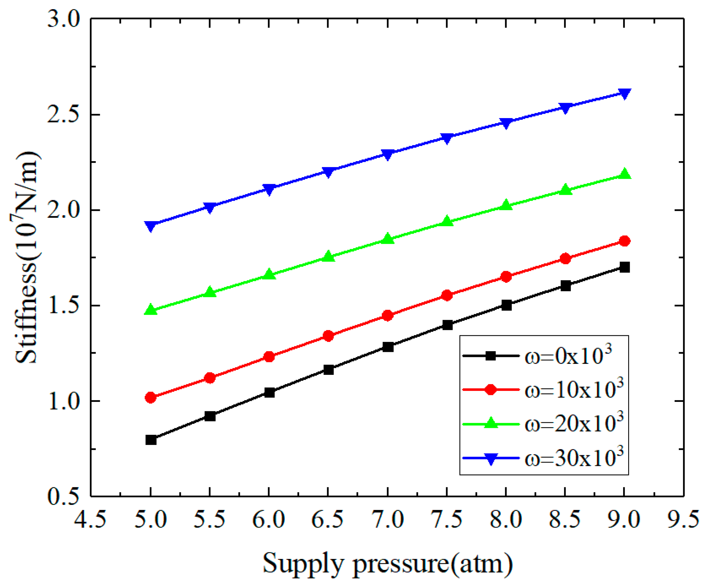
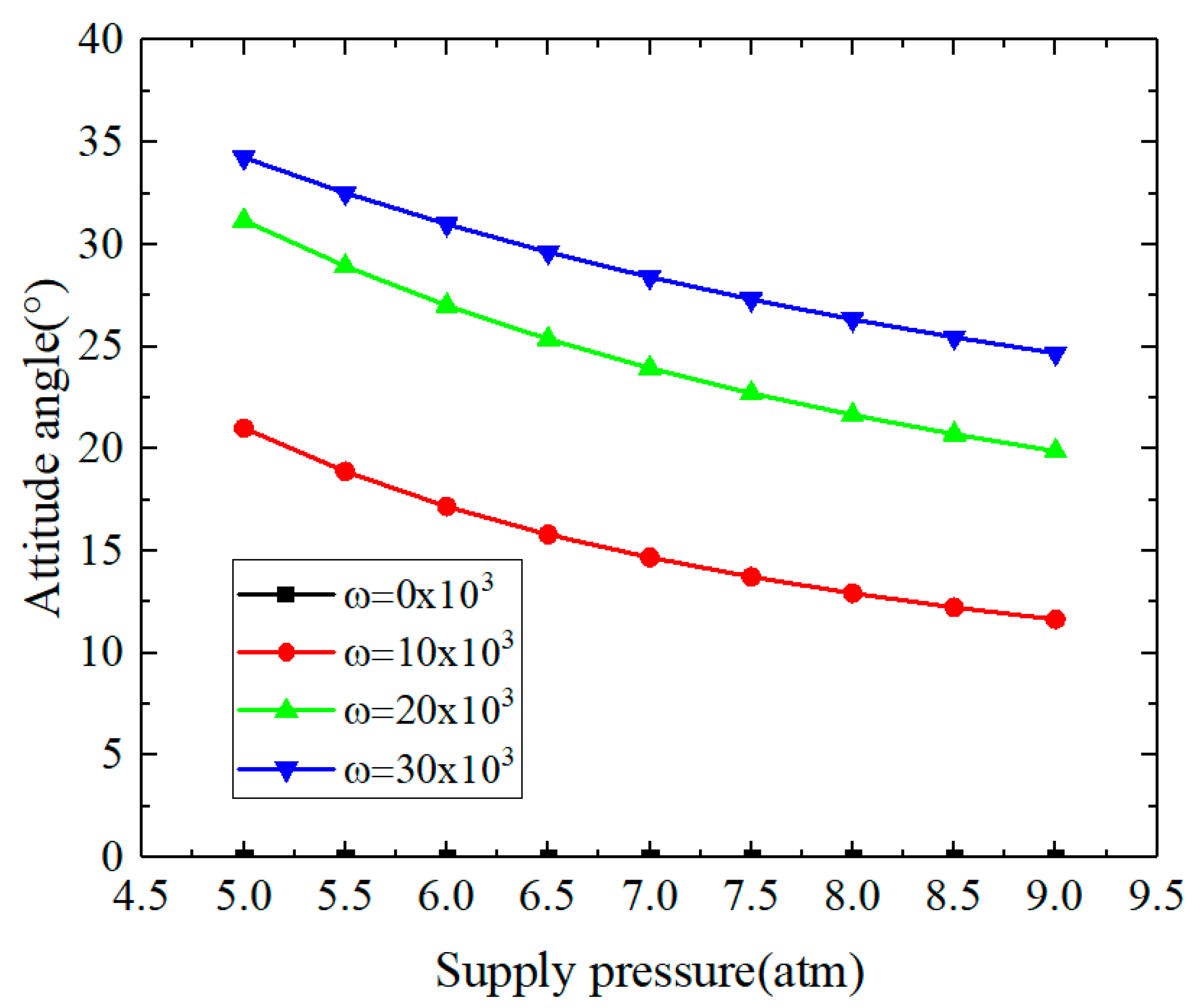
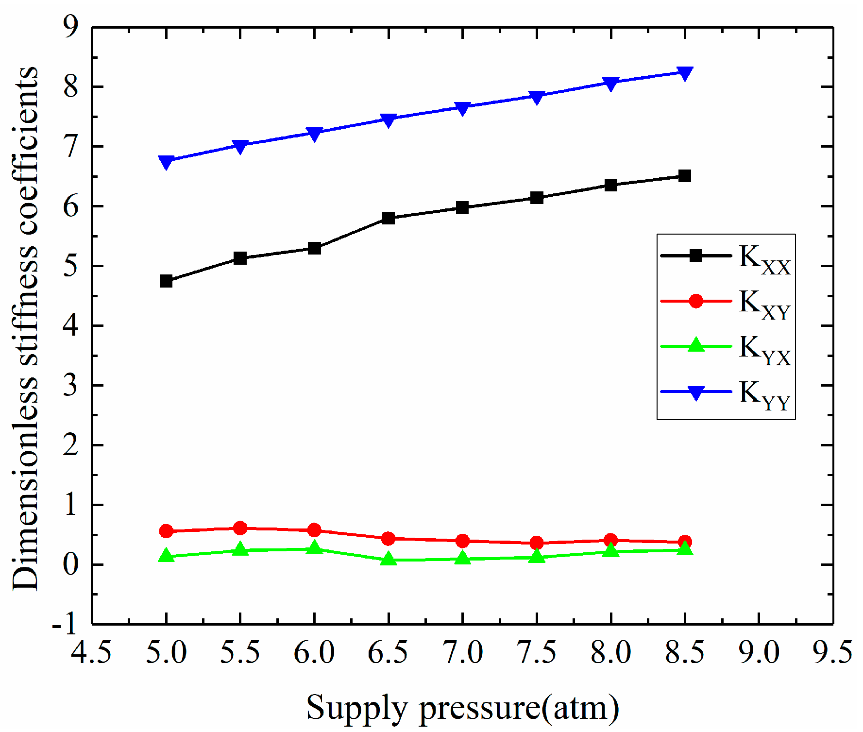
3.1.4. The Influences of Supply Pressure

In this section, the reference parameters are c = 15   μ m ,   d 0 = 0.2   m m ,   ε = 0.4 and the variable parameters are the supply pressure and rotational speed. Figure 15, Figure 16 and Figure 17 give the effects of the supply pressure on the bearing capacity, static stiffness and attitude angle. As shown in Figure 15, the bearing capacity and stiffness increase with the increase of the supply pressure. This is because the increase of the external air supply pressure strengthens the static pressure effect of the aerostatic bearing, which increases the bearing capacity and stiffness. Therefore, in order to improve the bearing capacity and static stiffness of the aerostatic gas bearing, the supply pressure can be appropriately increased. However, as the excessive air supply pressure may lead to instability of the air hammer, the supply pressure cannot be too high [34]. As shown in Figure 17, under the hybrid state, the attitude angle decreases with the increase of the supply pressure. Under the pure-static state, the attitude angle is zero. Therefore, the enhanced the supply pressure can strengthen the static pressure effect, which results in the decrease of the attitude angle under the hybrid state.

3.2. Dynamic Performances

In this section, according to the Section 2 theory and method, the influences of different parameters on the dynamic performances (such as dynamic stiffness, dynamic coefficients, linear stability and so on) are studied as follows. The aerostatic bearings parameters used in this section can be seen in Table 3.

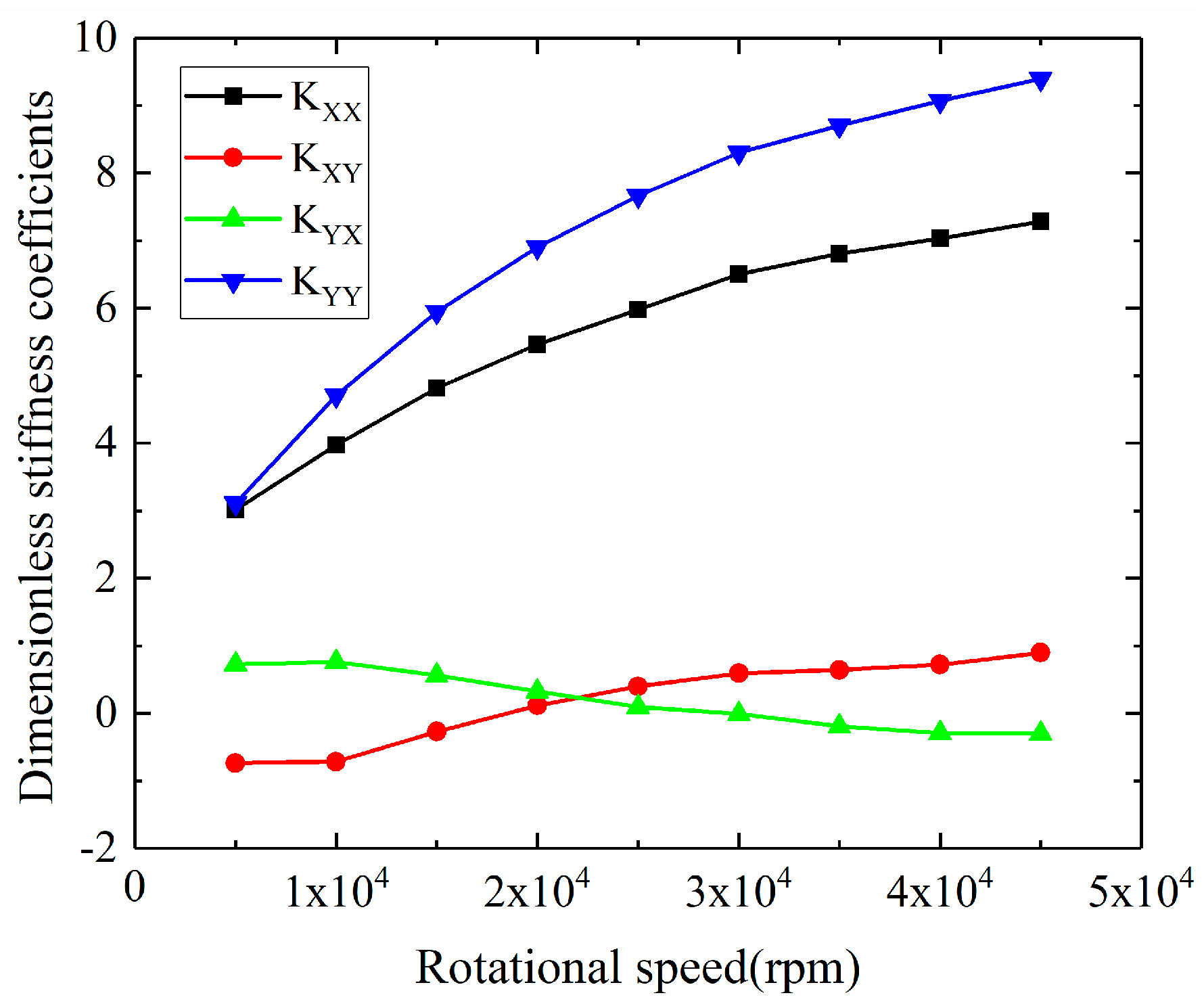
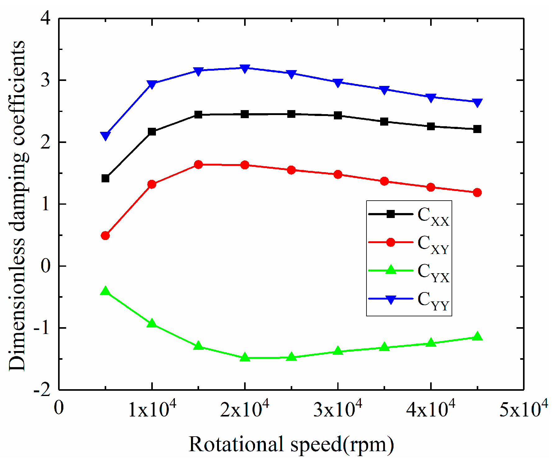
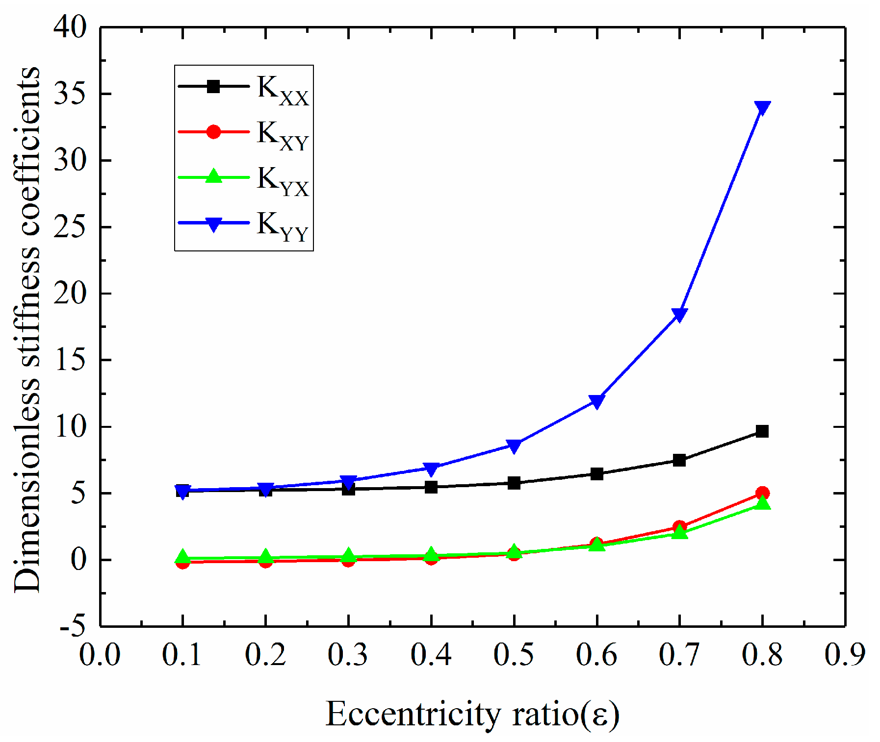
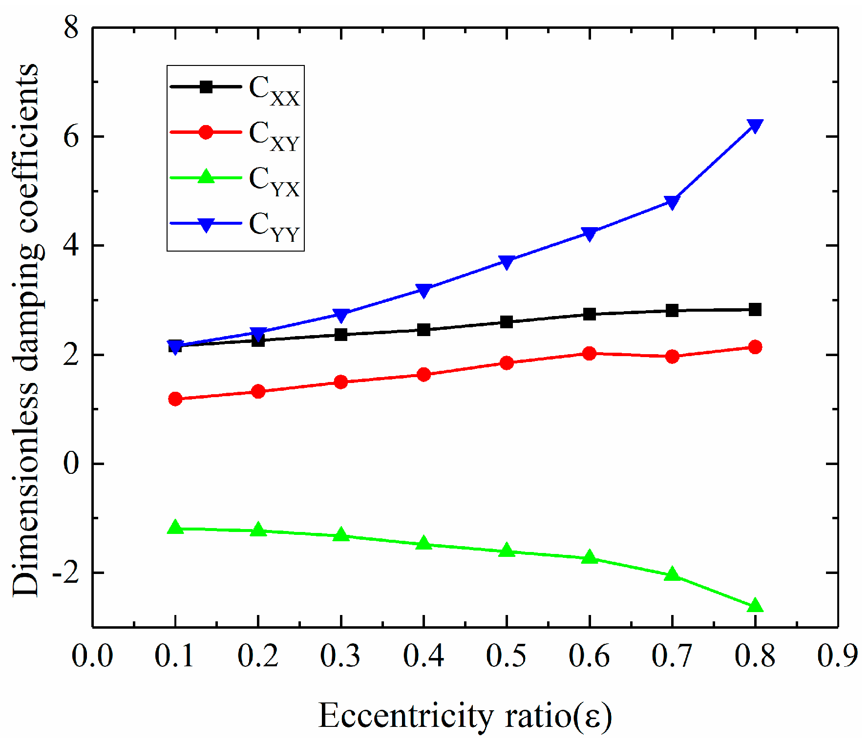
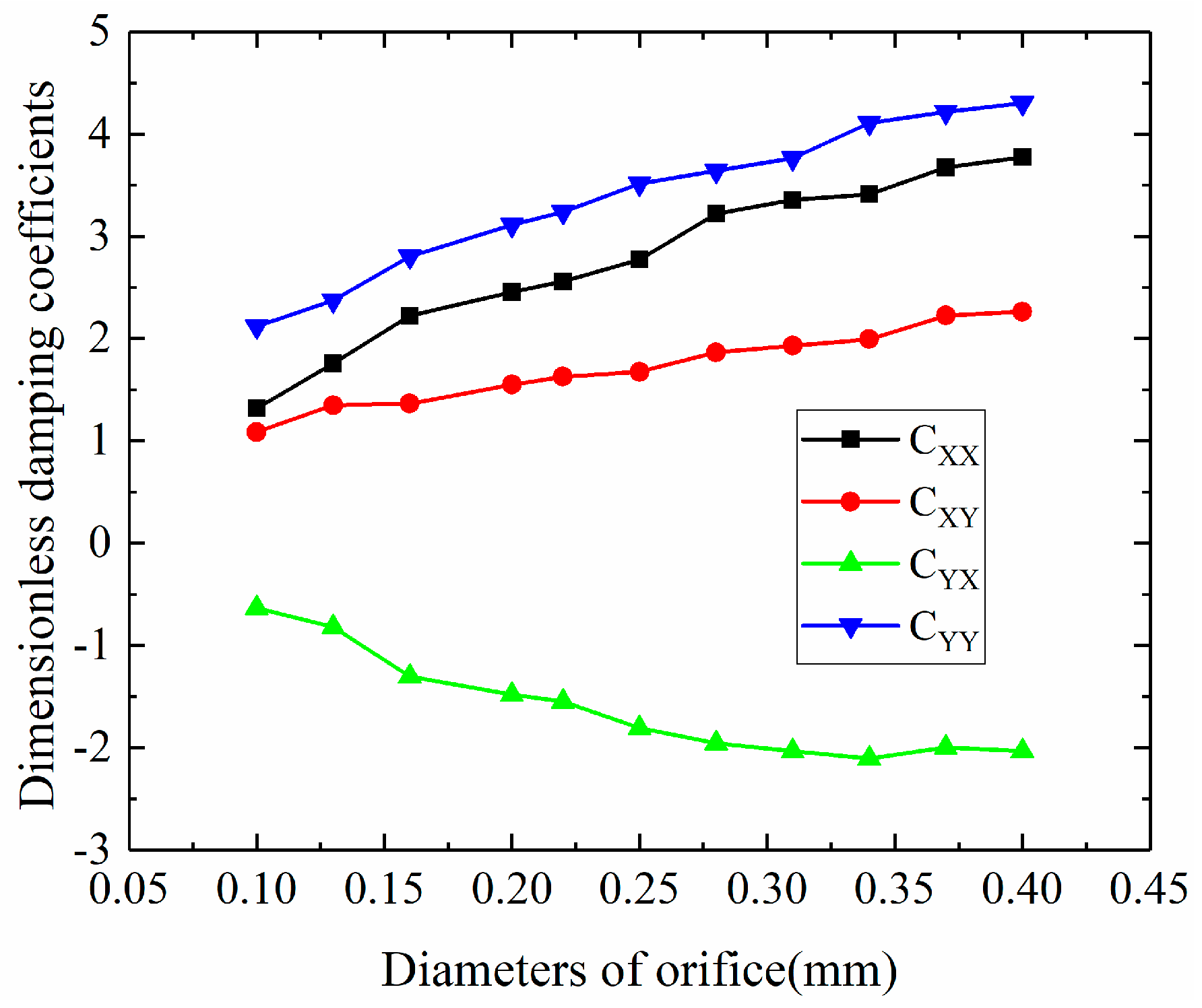
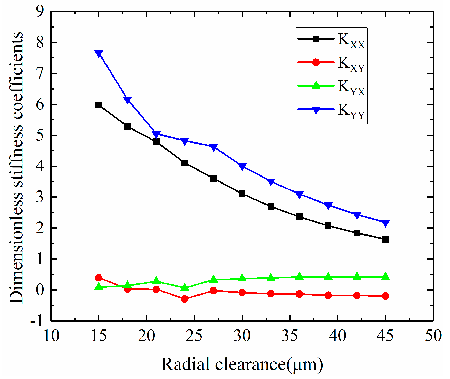
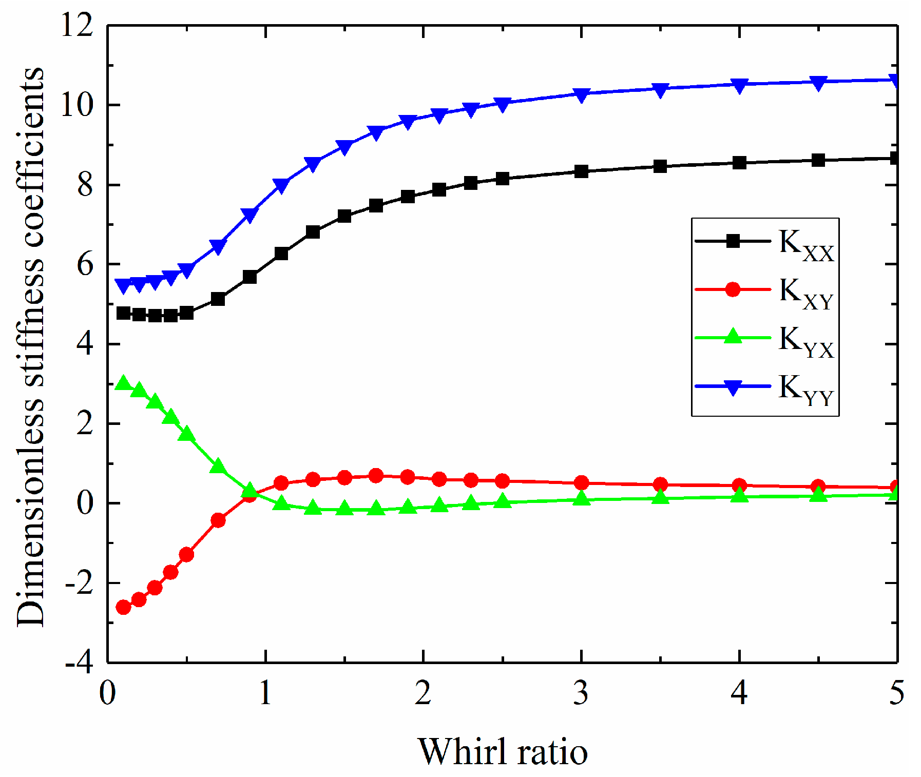
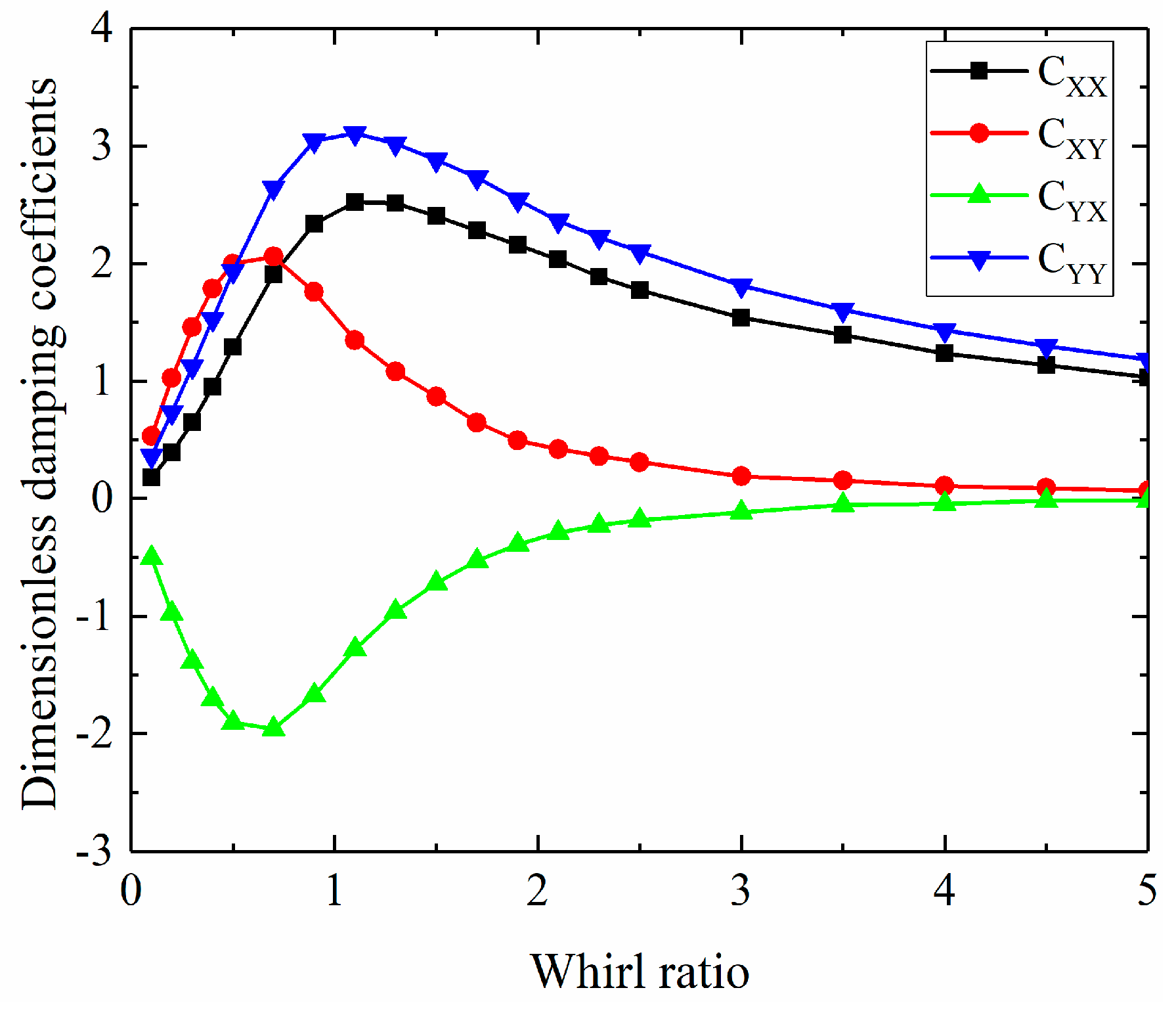
3.2.1. Dynamic Coefficients

As shown in Figure 18 and Figure 19, the effect of the rotational speed on the dynamic stiffness and damping coefficients is studied and the reference parameters are ε = 0.4 ,   d 0 = 0.2   m m ,   λ = 1 ,   c = 15   μ m ,   p s = 7   a t m . The bearing principal stiffness coefficients increase with the increase of the rotational speed and the principal stiffness K Y Y is bigger than the K X X , as shown in Figure 18. The reason is that the rotational effect strengthens with the increase of the speed and leads to the increase of the bearing principal stiffness. Moreover, as the direction of the bearing capacity is vertical, the principal stiffness along the vertical direction K Y Y is bigger than the principal stiffness along the horizontal direction K X X . Furthermore, the absolute value of the cross-couple stiffness K X Y and K Y X decreases first and then increases with the increase of the speed. However, the slope of the cross-couple stiffness is smaller than that of the principal stiffness. As shown in Figure 19, the principal damping and cross-couple damping change in the same way with rotational speed, i.e., they decrease first and then increase with an increase of the speed, while the principal damping along the vertical direction C Y Y is bigger than along the horizontal direction C X X . The reason for this is the same as the bearing principal stiffness.
As shown in Figure 20 and Figure 21, the effect of the eccentricity on the dynamic stiffness and damping coefficients is studied and the reference parameters are ω = 25,000   r p m ,   d 0 = 0.2   m m ,   λ = 1 ,   c = 15   μ m ,   p s = 7   a t m . As shown in Figure 20, the bearing principal stiffness and slope of the principal stiffness increase with the increase of the eccentricity and the principal stiffness K Y Y and the slope of it is bigger than that of K X X . The reason is that the rotational effect strengthens with the increase of the eccentricity and leads to the increase of the bearing principal stiffness. Moreover, the rotational effect obviously strengthens at the high eccentricity. Furthermore, the absolute value of the cross-couple stiffness K X Y and K Y X increases slowly with the increase of the eccentricity. However, the sensitivity of the cross-couple stiffness is weaker than the principal stiffness. As shown in Figure 21, the principal damping and cross-couple damping change in the same way with eccentricity, i.e., they increase with an increase of the eccentricity.
As shown in Figure 22 and Figure 23, the effect of the orifice diameter on the dynamic stiffness and damping coefficients is studied and the reference parameters are ω = 25,000   r p m ,   ε = 0.4 ,   λ = 1 ,   c = 15   μ m ,   p s = 7   a t m . The principal stiffness increases and then decreases with the increase of the orifice diameter, while the principal stiffness is not too sensitive to the orifice diameter. The effect of the orifice diameter on the cross-couple stiffness K X Y and K Y X is opposite, in which the former decreases and the latter increases with the increase of the diameter. As shown in Figure 23, the principal and cross-couple damping enhance with the increase of the orifice diameter.
As shown in Figure 24 and Figure 25, the effect of the radial clearance on the dynamic stiffness and damping coefficients is studied and the reference parameters are ω = 25,000   r p m ,   d 0 = 0.2   m m ,   λ = 1 ,   ε = 0.4 ,   p s = 7   a t m . As shown in the two figures, the principal and cross-couple stiffness and damping coefficients decrease with increase of the radial clearance. As the rotational speed is 25,000 rpm, the aerostatic bearing is under a hybrid state, in which the rotational effect plays the main role in the performances of the aerostatic bearings. The rotational effect will be weakened by increasing the radial clearance, which results in the decrease of the dynamics’ coefficients.
As shown in Figure 26 and Figure 27, the effect of the supply pressure on the dynamic stiffness and damping coefficients is investigated and the reference parameters are ω = 25,000   r p m ,   d 0 = 0.2   m m ,   λ = 1 , ε = 0.4 ,   c = 15   μ m . The static pressure effect is enhanced by increasing the supply pressure and leads to the increase of the principal dynamic coefficients, as shown in Figure 26 and Figure 27. Moreover, the cross-couple dynamic coefficients are not sensitive to the supply pressure.
As shown in Figure 28 and Figure 29, the effect of the whirl ratio on the dynamic stiffness and damping coefficients is investigated and the reference parameters are ω = 25,000   r p m ,   d 0 = 0.2   m m ,   c = 15   μ m ,   ε = 0.4 ,   p s = 7   a t m . As shown in these figures, the dynamic stiffness and damping are sensitivity to the whirl ration. With the increase of the whirl ratio, the principal stiffness increases continuously and finally tends to a constant value. Within the whirl ratio of 0.5~2, the slope of the principal stiffness is obviously higher than that of the other whirl ratio. The principal damping increases and then decreases with the increase of the whirl ratio. In addition, the cross-couple stiffness and damping tend to zero with an increase of the whirl ratio.

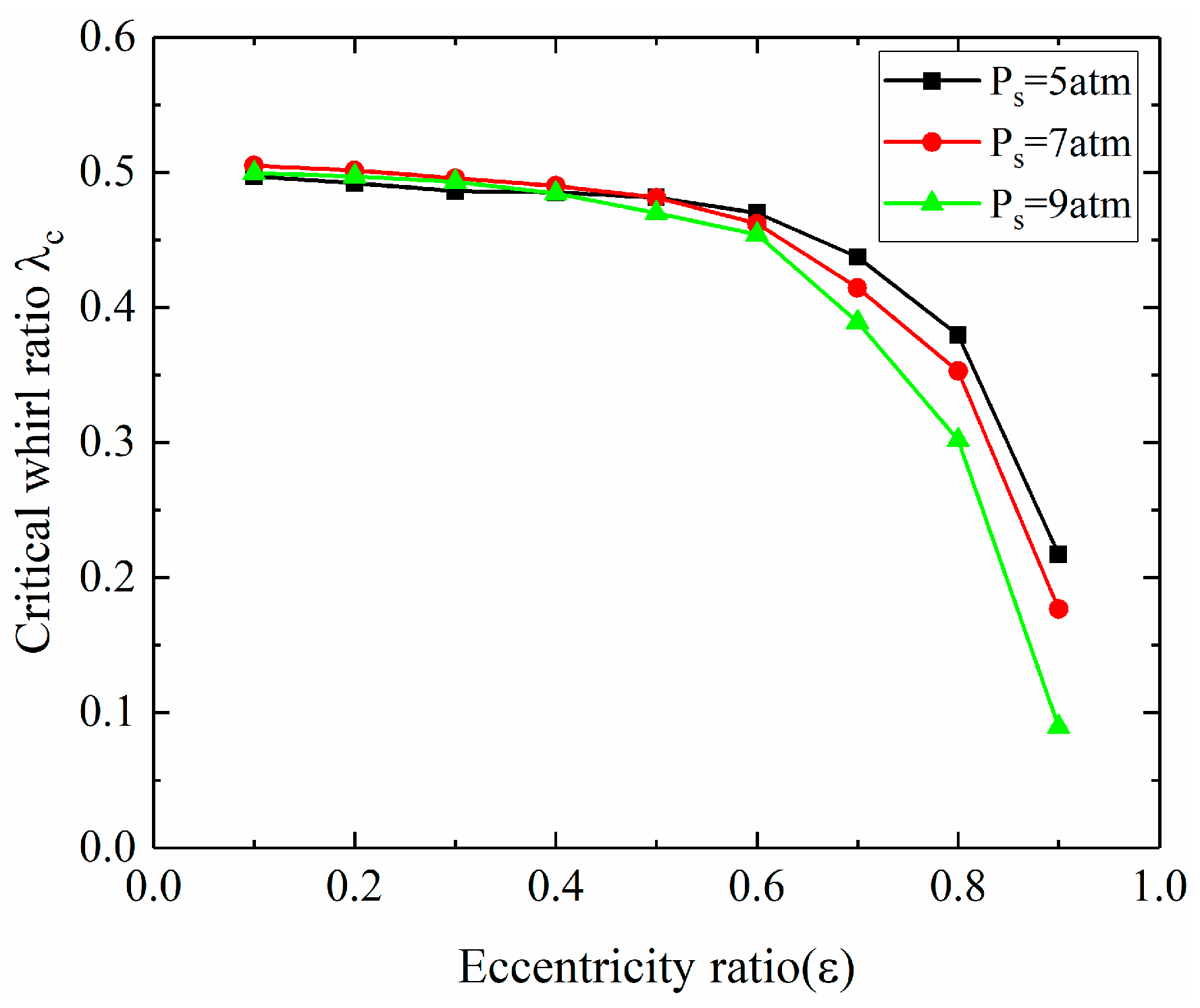
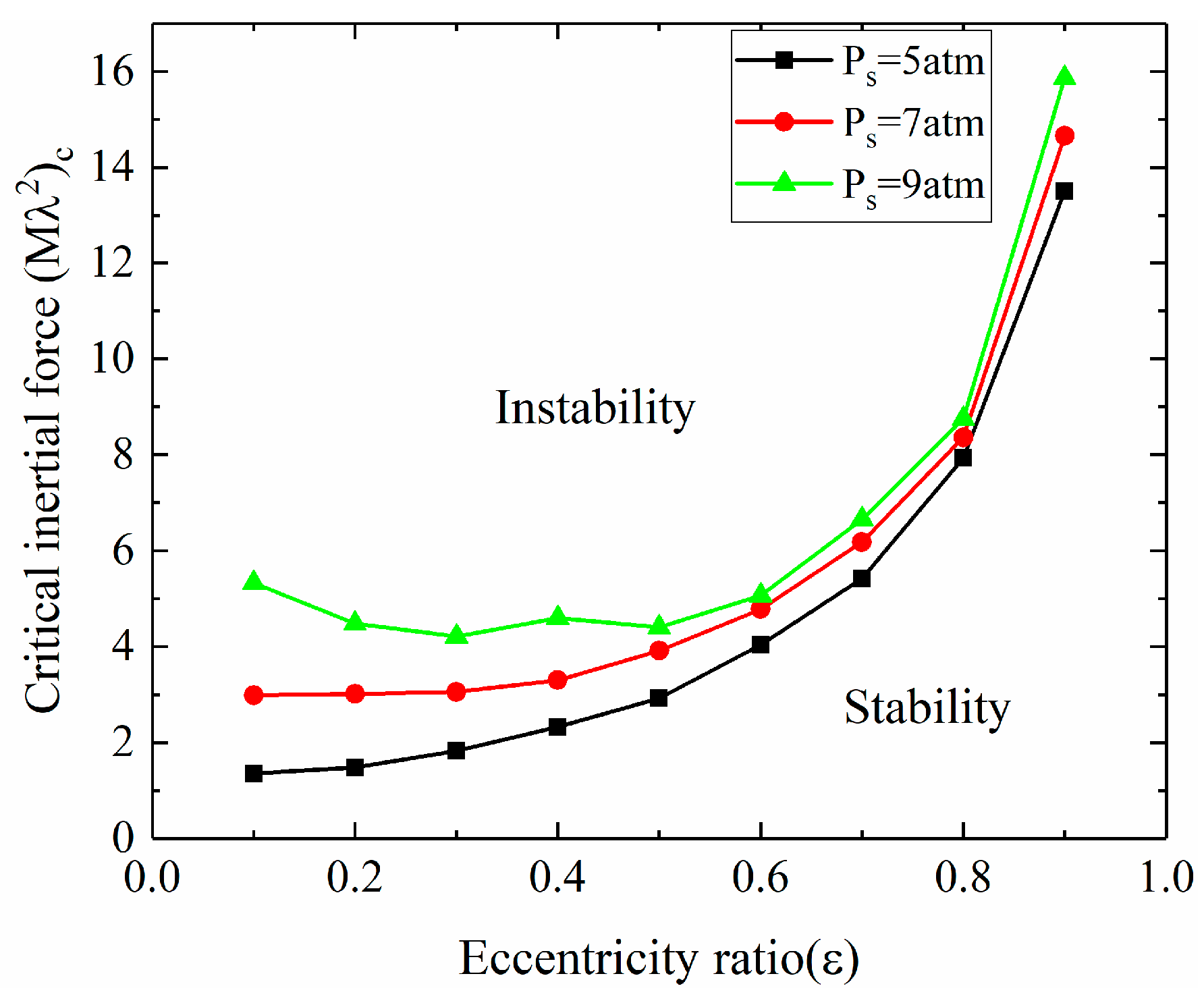
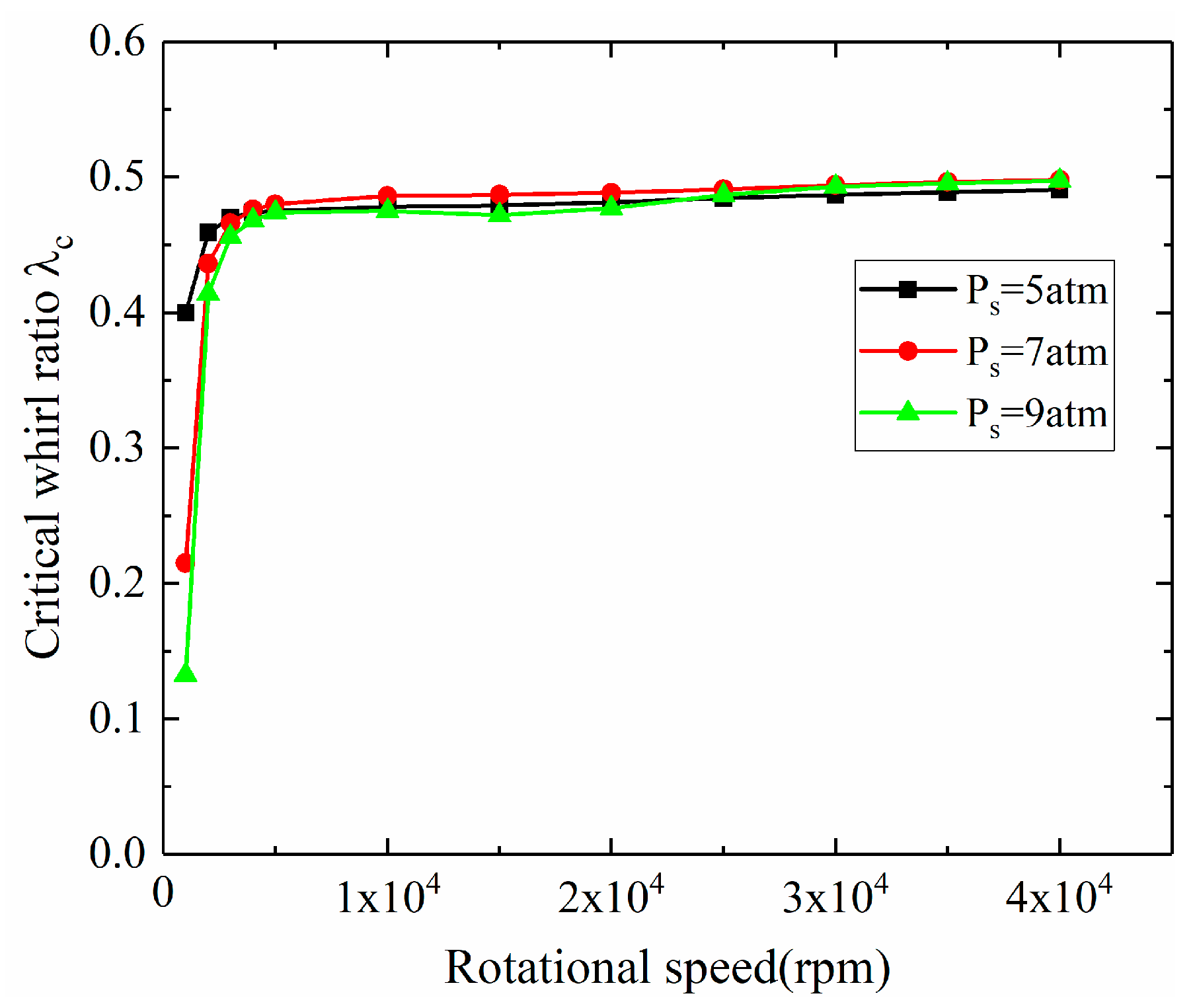
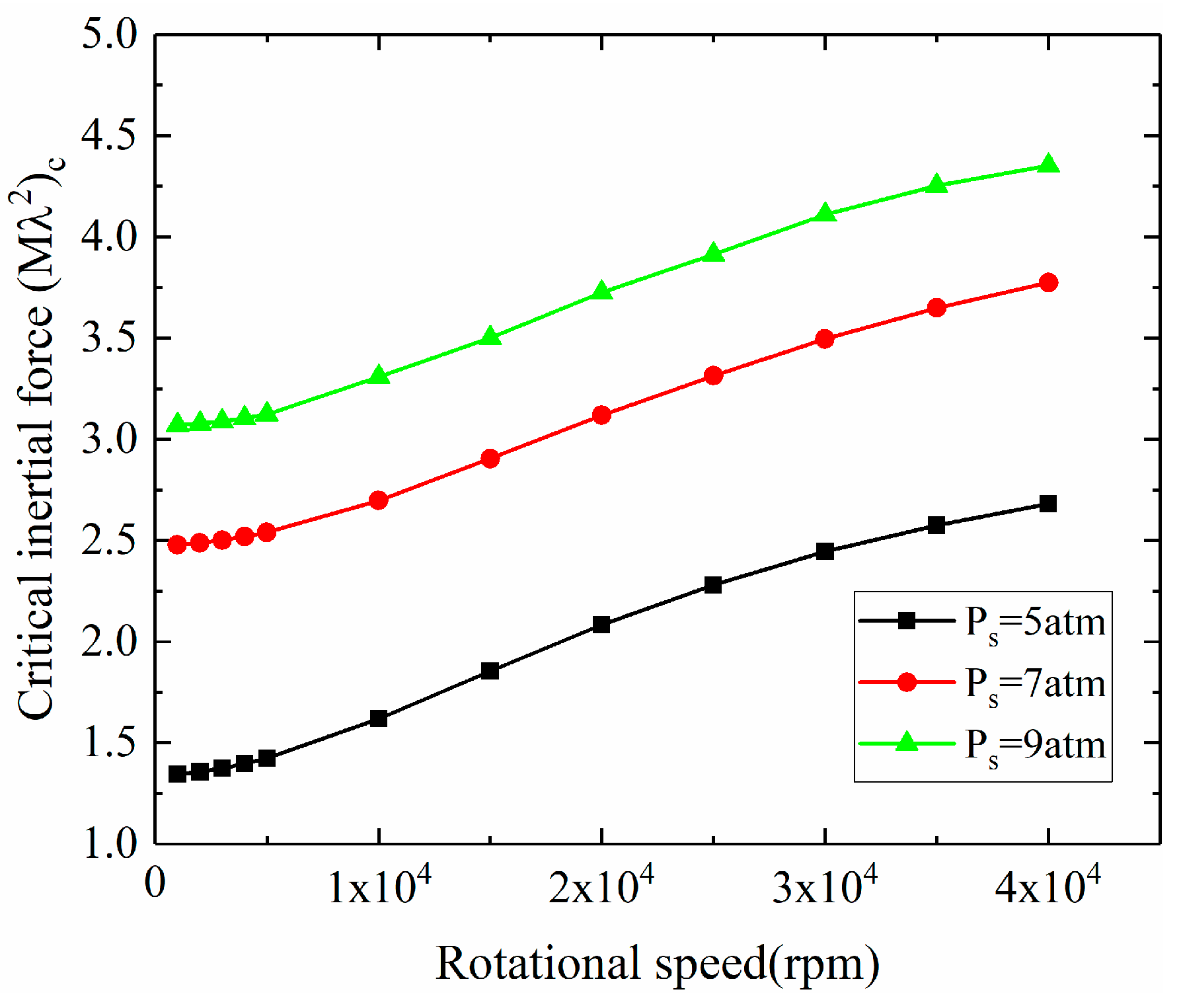
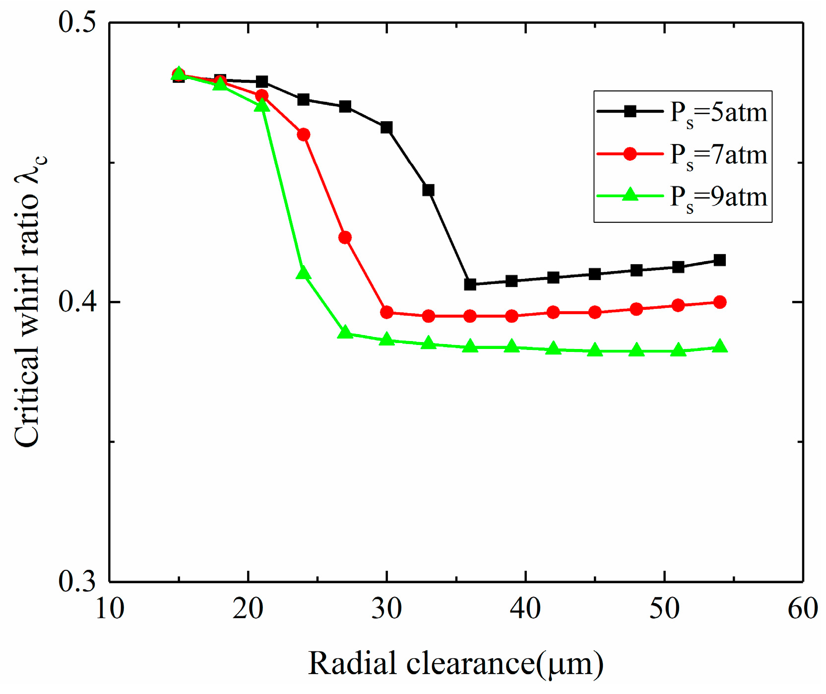
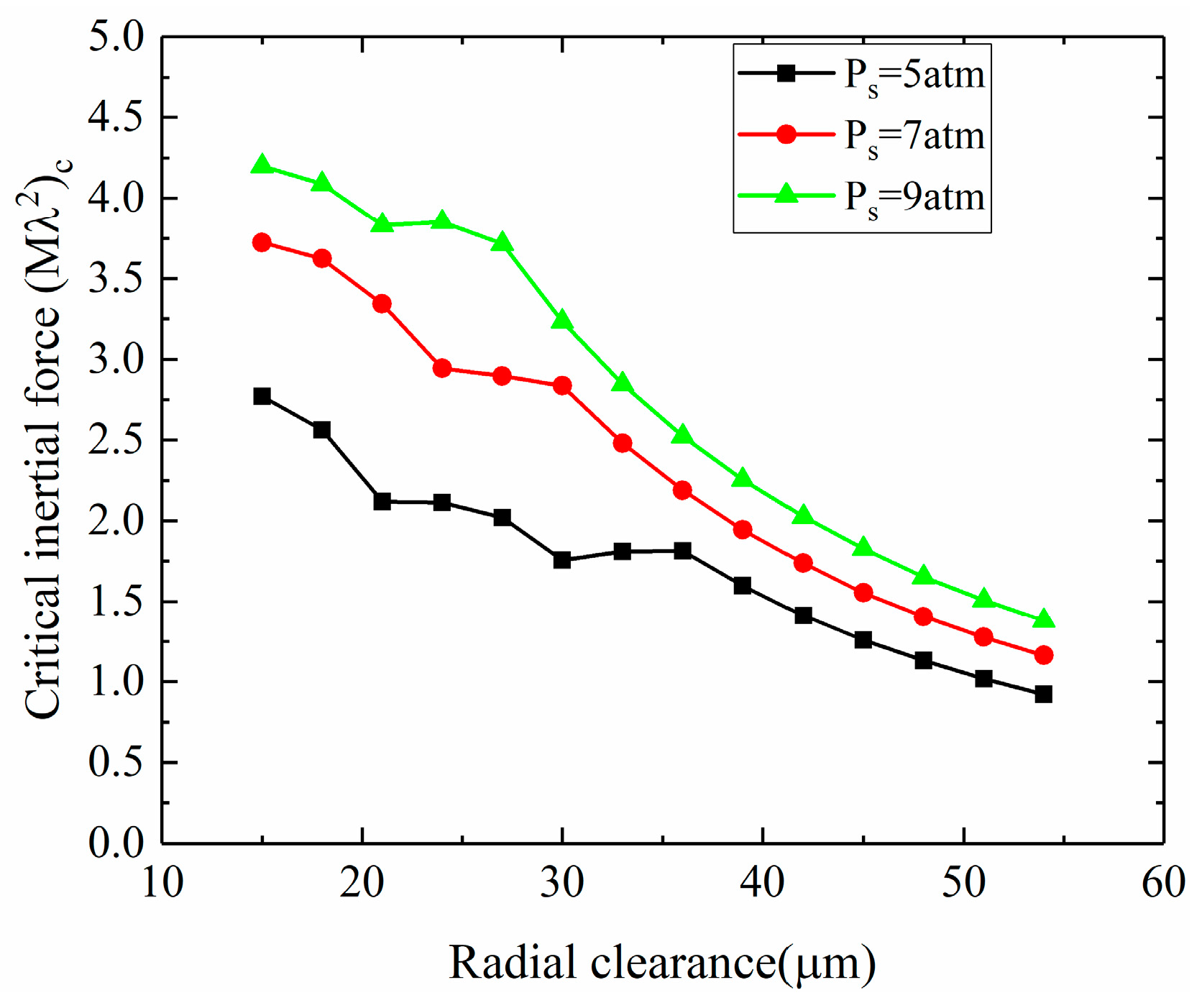
3.2.2. Linear Stability of the Gas–Rotor System

As mentioned above, the bearing dynamic stiffness and damping are sensitive to the geometry parameters and supply pressure. According to Equation (27), these parameters affect the linear stability of the aerostatic bearings. In this section, the critical whirl ratio and critical inertial force are used to represent the linear stability of the aerostatic bearing-rotor system.
Based on the study of Section 3.1.1, combined with the motion of the rigid rotor system, the linear stability will be studied by solving Equation (27) in the following. The main content contains the influence of the eccentricity, rotational speed, supply pressure and radial clearance on the critical whirl ratio and critical inertial force.
The influence of the eccentricity on the critical whirl ratio and critical inertial force under different supply pressure is shown in Figure 30 and Figure 31. As shown in Figure 30, under the lower eccentricity, the critical whirl ratio λ c is almost equal to 0.5, which is the “half-speed whirl” instability phenomenon. The λ c decreases with the increase of the eccentricity and the reduction is more obvious under the high eccentricity condition. Furthermore, the λ c decreases as the supply pressure increases and the decrease of the λ c with the supply pressure is more obvious under the high eccentricity. As shown in Figure 31, the critical inertial force ( M λ 2 ) c increases with the increase of the eccentricity and the slope of the increase is bigger under the high eccentricity condition. Moreover, for a certain eccentricity, ( M λ 2 ) c increases with the increase of the supply pressure and the slope of the increase is more obvious under the low eccentricity.
As shown in Figure 32 and Figure 33, the influence of the rotational speed on the critical whirl ratio and critical inertial force under different supply pressure is investigated. As shown in Figure 32, the λ c increases rapidly with the increase of the rotational speed under the low-speed condition and then tends to be a constant value (slightly less than 0.5) under high speed. As shown in Figure 33, the ( M λ 2 ) c also increases with the increase of the speed. Furthermore, the λ c will be reduced by an increase in the supply pressure and ( M λ 2 ) c will be improved by increased the supply pressure under different rotational speed conditions.
As shown in Figure 34 and Figure 35, the influence of the radial clearance on the critical whirl ratio and critical inertial force under different supply pressure is investigated. As shown in Figure 34, the λ c decreases rapidly with the increase of the radial clearance under the low radial clearance condition and the λ c is not sensitive to the radial clearance under high radial clearance conditions. As shown in Figure 35, the reduces with the increase of the radial clearance. Moreover, the supply pressure can improve the ( M λ 2 ) c and reduce the λ c under different radial clearance.

4. Conclusions

In this paper, the steady state and dynamic Reynolds equation were solved by FDM and the motion equation of a rigid rotor-bearing system was solved to study the linear stability of aerostatic bearings combined with the dynamic coefficients. Based on the theory, the effects of the different parameters on the static and dynamic performances of the aerostatic bearings were studied in detail. The main conclusions shown are as follows:
(1) In the case of the rotational speed effect, when the speed is low (in this paper, the speed is under 10,000 rpm), the static pressure effect plays the main role on the steady performances (such as load capacity and static stiffness), while the rotational effect plays an important role on the steady performances under high speed (in this paper, the speed is over 10,000 rpm).
(2) The whirl ratio plays an important role in the dynamic coefficients. The principal stiffness increases with the increase of the whirl ratio and the cross-couple stiffness tends to be zero with the whirl ratio. Moreover, the principal damping increases first and then decreases with the increase of the whirl ratio. The cross-couple damping also tends to be zero with the increase of the whirl ratio.
(3) As the supply pressure and eccentricity increase, the critical whirl ratio decreases and the critical inertial force increases. The critical whirl ratio and critical inertial force increase with the increase of the rotational speed and the critical whirl ratio tends to 0.5. In addition, the critical whirl ratio increases first and then decreases to a constant with the increase of the radial clearance, while the critical inertial force decreases.

Author Contributions

The author’s contributions can be seen in the follows. The contributions of J.Z. are conceptualization and writing—original draft; the contributions of Z.D. is formal analysis; the contributions of K.Z. are formal analysis and methodology; the contributions of H.J. is funding acquisition; the contributions of T.Y. are investigation and methodology; the contributions of Z.S. is investigation; the contributions of C.C. is formal analysis; the contributions of Y.C. is formal analysis; the contributions of Z.X. and D.W. are formal analysis and investigation; the contributions of J.S. is writing—review & editing. All authors have read and agreed to the published version of the manuscript.

Funding

The present research has been funded by the National Science and Technology Major Project of China (J2019-IV-0005-0072 and 2017-I-0008-0009); the authors would like to sincerely express their appreciation.

Data Availability Statement

The datasets used and/or analyzed during the current study are available from the corresponding author upon reasonable request.

Conflicts of Interest

The authors declare no conflict of interest.

Nomenclature

c radial clearance p a , P a ambient pressure
C d discharge coefficient p s , P s supply gauge pressure
d 0 diameter of orifices R radius of journal bearing
D diameter of journal bearing t , τ time, dimensionless time
e eccentricity u circumferential velocity
A 0 , B 0 , C 0 , D 0 , E 0 A X , B X , C X , D X , E X coefficient matrices in solution of Reynolds equation w axial velocity
k x x , k x y , k y x , k y y c x x , c x y , c y x , c y y dynamic coefficients W load capacity
K x x , K x y , K y x , K y y C x x , C x y , C y x , C y y dimensionless dynamic coefficients x , X circumferential coordinate
K w static stiffness y , Y radial coordinate
k e q inertial force z , Z axial coordinate
K e q dimensionless inertial force ε eccentricity ratio, ε = e / c
h , H film thickness, H = h / c ρ , ρ a gas density and gas density under atmosphere pressure
L length of the bearing ω rotational speed of journal
H X , H Y differential term of film thickness ω s journal perturbation rotational speed
m r rigid rotor mass λ whirl ratio
M ¯ dimensionless rotor mass Λ bearing number
Q r dimensionless mass flow rate at rth orifice φ 0 attitude angle
Q r X , Q r Y differential term of dimensionless mass flow rate at rth orifice κ ratio of specific heats of gas
pgas pressure δ Kronecker function
P 0 the dimensionless steady pressure i , i 1 , i + 1 , j , j 1 , j + 1 the subscript along circumference and axial direction, which indicates the position of the pressure
P X , P Y differential term of film pressuresubscript c the critical parameters
x ˙ , x ¨ , y ˙ , y ¨ velocity and acceleration along X and Y direction

Appendix A

Q r X = { Γ s p s C d 2 ρ a p a π d 0 c ( 2 κ + 1 ) κ κ 1 H X i , j   ; i f p 0 r i , j p s ( 2 κ + 1 ) κ κ 1 Γ s p s C d 2 ρ a p a π d 0 c κ κ 1 { H X ( P 0 r i , j P s ) 2 κ ( P 0 i , j P s ) κ + 1 κ + H 0 [ 2 κ ( P 0 r i , j P s ) 2 κ 1 1 P s κ + 1 κ ( P 0 r i , j P s ) 1 κ 1 P s ] 2 ( P 0 r i , j P s ) 2 κ ( P 0 r i , j P s ) κ + 1 κ } ; i f p 0 r i , j p s > ( 2 κ + 1 ) κ κ 1
Q r Y = { Γ s p s C d 2 ρ a p a π d 0 c ( 2 κ + 1 ) κ κ 1 H Y i j   ; i f p 0 r i , j p s ( 2 κ + 1 ) κ κ 1 Γ s p s C d 2 ρ a p a π d 0 c κ κ 1 { H Y ( P 0 r i , j P s ) 2 κ ( P 0 r i , j P s ) κ + 1 κ + H 0 [ 2 κ ( P 0 r i , j P s ) 2 κ 1 1 P s κ + 1 κ ( P 0 r i , j P s ) 1 κ 1 P s ] 2 ( P 0 r i , j P s ) 2 κ ( P 0 r i , j P s ) κ + 1 κ } ; i f p 0 r i , j p s > ( 2 κ + 1 ) κ κ 1

References

  1. Zhang, J.; Zou, D.; Ta, N.; Rao, Z. Numerical research of pressure depression in aerostatic thrust bearing with inherent orifice. Tribol. Int. 2018, 123, 385–396. [Google Scholar] [CrossRef]
  2. Zhang, J.; Zou, D.; Ta, N.; Rao, Z.; Ding, B. A numerical method for solution of the discharge coefficients in externally pressurized gas bearings with inherent orifice restrictors. Tribol. Int. 2018, 125, 156–168. [Google Scholar] [CrossRef]
  3. Dal, A.; Karaçay, T. Effects of angular misalignment on the performance of rotor-bearing systems supported by externally pressurized air bearing. Tribol. Int. 2017, 111, 276–288. [Google Scholar] [CrossRef]
  4. Zhu, X.; San Andrés, L. Rotordynamic Performance of Flexure Pivot Hydrostatic Gas Bearings for Oil-Free Turbomachinery. J. Eng. Gas Turbines Power 2007, 129, 1020–1027. [Google Scholar] [CrossRef]
  5. Zhang, J.; Han, D.; Song, M.; Xie, Z.; Zou, D. Theoretical and experimental investigation on the effect of supply pressure on the nonlinear behaviors of the aerostatic bearing-rotor system. Mech. Syst. Signal Process. 2021, 158, 107775. [Google Scholar] [CrossRef]
  6. Zhang, J.; Han, D.; Xie, Z.; Huang, C.; Su, Z. Nonlinear behaviors analysis of high-speed rotor system supported by aerostatic bearings. Tribol. Int. 2022, 170, 107111. [Google Scholar] [CrossRef]
  7. Qiu, Z.; Tieu, A. Misalignment effect on the static and dynamic characteristics of hydrodynamic journal bearings. J. Tribol. 1995, 117, 717–723. [Google Scholar] [CrossRef]
  8. Lahmar, M.; Frihi, D.; Nicolas, D. The effect of misalignment on performance characteristics of engine main crankshaft bearings. Eur. J. Mech.-A/Solids 2002, 21, 703–714. [Google Scholar] [CrossRef]
  9. Lv, F.; Rao, Z.; Ta, N.; Jiao, C. Mixed-lubrication analysis of thin polymer film overplayed metallic marine stern bearing considering wall slip and journal misalignment. Tribol. Int. 2017, 109, 390–397. [Google Scholar] [CrossRef]
  10. Lv, F.; Jiao, C.; Ta, N.; Rao, Z. Mixed-lubrication analysis of misaligned bearing considering turbulence. Tribol. Int. 2018, 119, 19–26. [Google Scholar] [CrossRef]
  11. Wrblewski, P.; Iskra, A. Geometry of shape of profiles of the sliding surface of ring seals in the aspect of friction losses and oil film parameters. Combust. Engines 2016, 167, 38–52. [Google Scholar] [CrossRef]
  12. Rostek, E.; Babiak, M.; Wróblewski, E. The Influence of Oil Pressure in the Engine Lubrication System on Friction Losses. Procedia Eng. 2017, 192, 771–776. [Google Scholar] [CrossRef]
  13. Chen, C.-H.; Kang, Y.; Yang, D.-W.; Hwang, R.-M.; Shyr, S.-S. Influence of the number of feeding holes on the performances of aerostatic bearings. Ind. Lubr. Tribol. 2010, 62, 150–160. [Google Scholar] [CrossRef]
  14. Ise, T.; Miyatake, H.; Asami, T. Asymmetric Supply Type Hydrostatic Journal Gas Bearings to Support Large Load Rotors. J. Adv. Mech. Des. Syst. Manuf. 2012, 6, 149–157. [Google Scholar] [CrossRef] [Green Version]
  15. Du, J.; Zhang, G.; Liu, T.; To, S. Improvement on load performance of externally pressurized gas journal bearings by opening pressure-equalizing grooves. Tribol. Int. 2014, 73, 156–166. [Google Scholar] [CrossRef]
  16. Su, J.C.; Lie, K. Rotation effects on hybrid air journal bearings. Tribol. Int. 2003, 36, 717–726. [Google Scholar] [CrossRef]
  17. Yang, D.-W.; Chen, C.-H.; Kang, Y.; Hwang, R.-M.; Shyr, S.-S. Influence of orifices on stability of rotor-aerostatic bearing system. Tribol. Int. 2009, 42, 1206–1219. [Google Scholar] [CrossRef]
  18. Wang, X.; Xu, Q.; Wang, B.; Zhang, L.; Yang, H.; Peng, Z. Numerical Calculation of Rotation Effects on Hybrid Air Journal Bearings. Tribol. Trans. 2017, 60, 195–207. [Google Scholar] [CrossRef]
  19. Wang, X.; Xu, Q.; Wang, B.; Zhang, L.; Yang, H.; Peng, Z. Effect of surface waviness on the static performance of aerostatic journal bearings. Tribol. Int. 2016, 103, 394–405. [Google Scholar] [CrossRef]
  20. Lund, J. A theoretical analysis of whirl instability and pneumatic hammer for a rigid rotor in pressurized gas journal bearings. ASME J. Lubr. Technol 1967, 89, 154–166. [Google Scholar] [CrossRef]
  21. Wadhwa, S.; Sinhasan, R.; Singh, D. Analysis of orifice compensated externally pressurized gas bearings. Tribol. Int. 1983, 16, 203–211. [Google Scholar] [CrossRef]
  22. Han, D.-C.; Park, S.-S.; Kim, W.-J.; Kim, J.-W. A study on the characteristics of externally pressurized air bearings. Precis. Eng. 1994, 16, 164–173. [Google Scholar] [CrossRef]
  23. Su, J.C.; Lie, K. Rotor dynamic instability analysis on hybrid air journal bearings. Tribol. Int. 2006, 39, 238–248. [Google Scholar] [CrossRef]
  24. Chen, C.-H.; Yang, D.-W.; Kang, Y.; Hwang, R.-M.; Shyr, S.-S. The influence of orifice restriction on the stability of rigid rotor-aerostatic bearing system. In Proceedings of the ASME Turbo Expo 2009: Power for Land, Sea, and Air, Orlando, FL, USA, 8–12 June 2009; pp. 909–917. [Google Scholar]
  25. Chen, C.-H.; Tsai, T.-H.; Yang, D.-W.; Kang, Y.; Chen, J.-H. The comparison in stability of rotor-aerostatic bearing system compensated by orifices and inherences. Tribol. Int. 2010, 43, 1360–1373. [Google Scholar] [CrossRef]
  26. Morosi, S.; Santos, I.F. On the modelling of hybrid aerostatic-gas journal bearings. Proc. Inst. Mech. Eng. Part J J. Eng. Tribol. 2011, 225, 641–653. [Google Scholar] [CrossRef]
  27. Colombo, F.; Raparelli, T.; Viktorov, V. Externally pressurized gas bearings: A comparison between two supply holes configurations. Tribol. Int. 2009, 42, 303–310. [Google Scholar] [CrossRef]
  28. Otsu, Y.; Somaya, K.; Yoshimoto, S. High-speed stability of a rigid rotor supported by aerostatic journal bearings with compound restrictors. Tribol. Int. 2011, 44, 9–17. [Google Scholar] [CrossRef]
  29. Belforte, G.; Raparelli, T.; Viktorov, V. Modeling and identification of gas journal bearings: Self-acting gas bearing results. Trans.-Am. Soc. Mech. Eng. J. Tribol. 2002, 124, 716–724. [Google Scholar] [CrossRef]
  30. Viktorov, V.; Belforte, G.; Raparelli, T. Modeling and Identification of Gas Journal Bearings: Externally Pressurized Gas Bearing Results. J. Tribol. 2005, 127, 548–556. [Google Scholar] [CrossRef]
  31. Wang, X.; Xu, Q.; Huang, M.; Zhang, L.; Peng, Z. Effects of journal rotation and surface waviness on the dynamic performance of aerostatic journal bearings. Tribol. Int. 2017, 112, 1–9. [Google Scholar] [CrossRef]
  32. Xie, Z.; Jiao, J.; Yang, K. Theoretical and experimental study on the fluid-structure-acoustic coupling dynamics of a new water lubricated bearing. Tribol. Int. 2023, 177, 107982. [Google Scholar] [CrossRef]
  33. SHINICHIT. Gas Bearing: Design, Fabrication and Application; Aerospace Publishing House: Beijing, China, 1988. [Google Scholar]
  34. Ma, W.; Cui, J.; Liu, Y.; Tan, J. Improving the pneumatic hammer stability of aerostatic thrust bearing with recess using damping orifices. Tribol. Int. 2016, 103, 281–288. [Google Scholar] [CrossRef]
Figure 1. Schematic view of the aerostatic bearing: (a) XYZ plane; (b) YZ plane and XZ plane; (c) mid plane.
Lubricants 11 00130 g001
Figure 2. Computational domain of the Reynolds equation and grid structure.
Lubricants 11 00130 g002
Figure 3. Rigid rotor and aerostatic journal bearing system.
Lubricants 11 00130 g003
Figure 4. Flow chart of the solution of the critical whirl ratio and the critical inertial force.
Lubricants 11 00130 g004
Figure 5. The pressure distribution from the presented study and published paper [33]: (a) pressure distribution along with the circumferential direction; (b) pressure distribution along with the axial direction.
Lubricants 11 00130 g005
Figure 6. The effects of the eccentricity ratio and rotational speed on the load capacity (reference parameters: d 0 = 0.2   m m ,   p s = 7   a t m ,   c = 15   μ m ).
Lubricants 11 00130 g006
Figure 7. The effects of the eccentricity ratio and rotational speed on the steady stiffness (reference parameters: d 0 = 0.2   m m ,   p s = 7   a t m ,   c = 15   μ m ).
Lubricants 11 00130 g007
Figure 8. The effects of the eccentricity ratio and rotational speed on the attitude angle (reference parameters: d 0 = 0.2   m m ,   p s = 7   a t m ,   c = 15   μ m ).
Lubricants 11 00130 g008
Figure 9. The effects of radial clearance and rotational speed on the load capacity (reference parameters: d 0 = 0.2   m m ,   p s = 7   a t m ,   ε = 0.4 ).
Lubricants 11 00130 g009
Figure 10. The effects of radial clearance and rotational speed on the steady stiffness (reference parameters: d 0 = 0.2   m m ,   p s = 7   a t m ,   ε = 0.4 ).
Lubricants 11 00130 g010
Figure 11. The effects of radial clearance and rotational speed on the attitude angle (reference parameters: d 0 = 0.2   m m ,   p s = 7   a t m ,   ε = 0.4 ).
Lubricants 11 00130 g011
Figure 12. The effects of the diameter of the orifice on the load capacity (reference parameters: c = 15   μ m ,   p s = 7   a t m ,   ε = 0.4 ).
Lubricants 11 00130 g012
Figure 13. The effects of the diameter of the orifice on the steady stiffness (reference parameters: c = 15   μ m ,   p s = 7   a t m ,   ε = 0.4 ).
Lubricants 11 00130 g013
Figure 14. The effects of the diameter of the orifice on the attitude angle (reference parameters: c = 15   μ m ,   p s = 7   a t m ,   ε = 0.4 ).
Lubricants 11 00130 g014
Figure 15. The effects of supply pressure on the load capacity (reference parameters: c = 15   μ m ,   d 0 = 0.2   m m ,   ε = 0.4 ).
Lubricants 11 00130 g015
Figure 16. The effects of supply pressure on the steady stiffness (reference parameters: c = 15   μ m ,   d 0 = 0.2   m m ,   ε = 0.4 ).
Lubricants 11 00130 g016
Figure 17. The effects of supply pressure on the attitude angle (reference parameters: c = 15   μ m ,   d 0 = 0.2   m m ,   ε = 0.4 ).
Lubricants 11 00130 g017
Figure 18. The effect of rotational speed on the dynamic stiffness coefficients (reference parameters: ε = 0.4 ,   d 0 = 0.2   m m ,   λ = 1 ,   c = 15   μ m ,   p s = 7   a t m ).
Lubricants 11 00130 g018
Figure 19. The effect of rotational speed on the damping coefficients (reference parameters: ε = 0.4 ,   d 0 = 0.2   m m ,   λ = 1 ,   c = 15   μ m ,   p s = 7   a t m ).
Lubricants 11 00130 g019
Figure 20. The effect of the eccentricity ratio on the dynamic stiffness coefficients (reference parameters: ω = 25,000   r p m ,   d 0 = 0.2   m m ,   λ = 1 ,   c = 15   μ m ,   p s = 7   a t m ).
Lubricants 11 00130 g020
Figure 21. The effect of the eccentricity ratio on the damping coefficients (reference parameters: ω = 25,000   r p m ,   d 0 = 0.2   m m ,   λ = 1 ,   c = 15   μ m ,   p s = 7   a t m ).
Lubricants 11 00130 g021
Figure 22. The effect of the diameter of the orifice on the dynamic stiffness coefficients (reference parameters: ω = 25,000   r p m ,   ε = 0.4 , λ = 1 ,   c = 15   μ m ,   p s = 7   a t m ).
Lubricants 11 00130 g022
Figure 23. The effect of the diameter of the orifice on the damping coefficients (reference parameters: ω = 25,000   r p m ,   ε = 0.4 ,   λ = 1 ,   c = 15   μ m ,   p s = 7   a t m ).
Lubricants 11 00130 g023
Figure 24. The effect of radial clearance on the dynamic stiffness coefficients (reference parameters: ω = 25,000   r p m ,   d 0 = 0.2   m m ,   λ = 1 ,   ε = 0.4 ,   p s = 7   a t m ).
Lubricants 11 00130 g024
Figure 25. The effect of radial clearance on the damping coefficients (reference parameters: ω = 25,000   r p m ,   d 0 = 0.2   m m ,   λ = 1 ,   ε = 0.4 ,   p s = 7   a t m ).
Lubricants 11 00130 g025
Figure 26. The effect of supply pressure on the dynamic stiffness coefficients (reference parameters: ω = 25,000   r p m ,   d 0 = 0.2   m m ,   λ = 1 , ε = 0.4 ,   c = 15   μ m ).
Lubricants 11 00130 g026
Figure 27. The effect of supply pressure on the damping coefficients (reference parameters: ω = 25,000   r p m ,   d 0 = 0.2   m m ,   λ = 1 , ε = 0.4 ,   c = 15   μ m ).
Lubricants 11 00130 g027
Figure 28. The effect of whirl ratio on the dynamic stiffness coefficients (reference parameters: ω = 25,000   r p m ,   d 0 = 0.2   m m ,   c = 15   μ m ,   ε = 0.4 ,   p s = 7   a t m ).
Lubricants 11 00130 g028
Figure 29. The effect of whirl ratio on the damping coefficients (reference parameters: ω = 25,000   r p m ,   d 0 = 0.2   m m ,   c = 15   μ m ,   ε = 0.4 ,   p s = 7   a t m ).
Lubricants 11 00130 g029
Figure 30. The effect of the eccentricity ratio on the critical whirl ratio.
Lubricants 11 00130 g030
Figure 31. The effect of the eccentricity ratio on the critical inertial force.
Lubricants 11 00130 g031
Figure 32. The effect of rotational speed on the critical whirl ratio.
Lubricants 11 00130 g032
Figure 33. The effect of rotational speed on the critical inertial force.
Lubricants 11 00130 g033
Figure 34. The effect of radial clearance on the critical whirl ratio.
Lubricants 11 00130 g034
Figure 35. The effect of radial clearance on the critical inertial force.
Lubricants 11 00130 g035
Table 1. The calculation results with different numbers of m and n.
The Number of mThe Number of nLoad Capacity/N
1632177.33
3232174.80
3264173.23
4880171.67
6496171.15
64128170.83
Table 2. The calculation parameters used in this section.
Calculation ParametersValue
Bearing diameter (D)25 mm
Bearing length (L)50 mm
Gas density ( ρ )1.204 kg/m3
Gas viscosity ( η )1.82·10−5 Ns/m2
Ration of specific heat of gas ( κ )1.4
Atmospheric pressure (atm) ( p a )101,325 Pa
Rows of the orifice2
The orifice number of each row orifice8
Table 3. The calculation parameters used in this section.
Calculation ParametersValue
Bearing diameter (D)50 mm
Bearing length (L)50 mm
Gas density ( ρ )1.204 kg/m3
Gas viscosity ( η )1.82·10−5 Ns/m2
Ration of specific heats of gas ( κ )1.4
Atmospheric pressure (atm) ( p a )101,325 Pa
Rows of the orifice2
The orifice number of each row orifice8
Disclaimer/Publisher’s Note: The statements, opinions and data contained in all publications are solely those of the individual author(s) and contributor(s) and not of MDPI and/or the editor(s). MDPI and/or the editor(s) disclaim responsibility for any injury to people or property resulting from any ideas, methods, instructions or products referred to in the content.

