Review

A Critical Review of High-Temperature Tribology and Cutting Performance of Cermet and Ceramic Tool Materials

1
Institute for Advanced Ceramics, School of Materials Science and Engineering, Harbin Institute of Technology, Harbin 150001, China
2
Mechanical Engineering Department, Faculty of Engineering at Shoubra, Benha University, Cairo 11672, Egypt
*
Author to whom correspondence should be addressed.
Lubricants 2023, 11(3), 122; https://doi.org/10.3390/lubricants11030122
Submission received: 14 January 2023 / Revised: 5 March 2023 / Accepted: 7 March 2023 / Published: 9 March 2023
(This article belongs to the Special Issue Recent Advances in High Temperature Tribology)

Abstract

:
Cermet materials exhibit advanced mechanical and tribological properties, and are widely used for tribology, elevated temperature, and machining applications due to their unique amalgamation of hardness, strength, and toughness. This paper presents a comprehensive overview of various cermet systems and recent advances in high-temperature tribology and cutting performance of cermet and ceramic tool materials. It outlines microstructural properties, such as lessening grain sizes, obtaining extended grains, lowering grain boundary phase content, amorphous grain boundary phases crystallizing, inter-granular phase strengthening, and managing crack propagation path. Additionally, surface processing or surface modifications, such as surface texturing, appropriate roughness, or coating technique, can optimize the ceramic and cermet tribological performances. The purpose of this study is to present some guidelines for the design of ceramics and cermets with reduced friction and wear and increased cutting performance. The current research progress concerning tribological properties and surface texturing of cutting tool inserts is critically identified. Lubrication techniques are required in commercial applications to increase the lifetime of cutting tools used in harsh conditions. Liquid lubricants are still commonly utilized in relative motion; however, they have the limitations of not working in extreme settings, such as high-temperature environments. As a result, global research is presently underway to produce new solid lubricants for use in a variety of such conditions. This review also provides a quick outline of current research on this topic.

1. Introduction

In recent decades, various initiatives have been undertaken to produce structural ceramics for various industrial applications and scientific research. Cermets are defined as heterogeneous mixtures of metal(s) or alloy(s) by (one or more) ceramic phases where the latter constitutes approximately 15 to 85% by volume; there is little solubility between ceramic and metallic phases at fabrication temperatures [1]. Cermets, in particular, are exceptional as they combine both features of metals and ceramics. Cermets are being utilized as components in various critical applications due to their exceptional mechanical and physical properties, which include high hardness, excellent wear resistance, lightweight design, oxidation resistance, high melting point, and good resistance to chemical attacks. The exceptional properties of cermets make them ideal for use as industrial material in a range of high-temperature applications, including engine parts, turbine pumps, heat exchangers, cutting tools, fusion reactors, heat engine components, armor plating, etc. [2,3,4]. Because ceramics and metals possess different constraints for use in many industrial applications, cermet materials have received special attention. The heat produced through friction can lead to problems for metals when used at high speeds. Metals may rust or corrode when utilized in moist environments. Ceramics, on the other hand, have thermal and chemical resistance; the use of ceramics helps alleviate these issues. However, the brittleness of ceramic materials causes catastrophic failures and fracture formation of ceramic equipment. The first attempts to use ceramic materials as tools took place in the 1950s. Ceramic tools, which offer comparable performance to superhard materials (e.g., cubic boron nitride and diamond) but with lower manufacturing costs, are currently the primary materials used for machining high-temperature alloys. The following are the main advantages of ceramic tools compared to low-cost HSS tools [5]:
  • Higher hardness and wear resistance. Ceramic tools have a substantially higher hardness than HSS tools, and the cutting speed is approximately ten times that of HSS tools, which can effectively improve machining efficiency.
  • Higher heat resistance. The hardness of ceramic tools can still be maintained at 80 HRA at 1200 °C, enabling dry cutting and meeting the requirements of green manufacturing.
  • Lower coefficient of friction. Low affinity with metal and low coefficients of friction can significantly reduce cutting forces and cutting temperatures, ensuring machining accuracy.
  • Higher chemical stability. It is not easy to produce adhesion with the metal, which can effectively reduce the adhesive wear of the tool and improve the tool’s lifetime.
In addition, high-temperature resistance, high toughness, and self-lubricating properties can be further achieved through fine regulation of the composition and microstructure of ceramic tools, enabling the application range of ceramic composite tools to be further broadened [6,7,8]. Approaches for lowering friction losses have grown in prominence in recent years, while high frictional coefficients and specific wear rates at machine element surface contacts cause failure and energy losses. During the metal cutting operation, approximately 20 % of the total energy is used to reduce the sliding friction at the rake and flank faces of the tool [9]. Furthermore, it has a negative effect on the cutting tool’s lifetime and machining efficiency [10,11,12,13]. As a result, minimizing friction would lower manufacturing costs and, hence, boost the economic interest of products. Therefore, lubricants or cutting fluids were used to reduce friction at the tool/workpiece interface and increase the lifetime of tools by cooling down the generated heat during the machining process, as shown in Figure 1, removing the formed chips and reducing the built-up edge formation. Tool coatings and tool surface texturing may be used [14,15,16,17].
Lubricants are divided into three categories—solid, semi-solid, and liquids. Ordinary liquids and grease-type semisolid lubricants have some drawbacks as they are not suitable for many specific applications that must now work in harsh conditions (such as extreme or cold temperatures, low vacuum, radiation atmosphere, corrosion environment, and higher contact pressures) [19]. As a result, liquid lubricants are used in normal working conditions at temperatures below 300 °C, despite their negative impact on human health and the environment [20,21]. Cutting fluids may produce serious health problems, such as lung infections and dermatological and genetic diseases [22]. Therefore, solid lubricants are preferred during the machining process because they are less poisonous, better for the environment, and have better biodegradability [23]. They have higher operating temperatures (more than 400 °C) and larger vacuum environments ( 10 3 m Bar) compared to liquids or semisolid lubricants. Solid lubricants can be created on sliding surfaces under ideal situations, producing a steady protective film between the contacting surfaces. Graphite, calcium fluoride, molybdenum disulfide, and boric acid are commonly used as lubricants in machining [24], with graphite and molybdenum disulfide (MoS 2 ) being the most prevalent in various applications [25]. In addition, soft metals, oxides, and rare-earth metal fluorides may also be used as solid lubricants, exhibiting frictional coefficients as small as 0.1 in certain conditions. The choice of solid lubricant, operating parameters, counter elements, force, velocity, etc., significantly influence the tribological properties [26,27,28]. We will discuss the various ceramic and cermet tool materials in the following section, including alumina-based ceramics, silicon nitride-based ceramics, and cermet materials. Each material has distinct features that make it ideal for a variety of cutting applications. We will gain a greater understanding of the benefits and drawbacks of ceramic and cermet tool materials in cutting tool applications by investigating the many types of ceramic and cermet tool materials.

2. Types of Ceramic Tool Materials

Currently, commercial ceramic tools are divided into four types: Si 3 N 4 -based ceramics, Al 2 O 3 -based ceramics, c-based ceramics, and cermet cutting tool materials [29,30]. In addition, new types of ceramic tool materials are being developed to meet the increasing demands for processing [31,32,33]. The mechanical characteristics of several kinds of ceramic tools are summarized in Table 1.

2.1. Aluminum Oxide-Based Ceramic Tools

Pure Al 2 O 3 ceramic tools with MgO as a sintering aid are the first types of ceramic tool materials used for the continuous finishing of cast iron, carbon steel, and alloy steel. They possess low manufacturing costs, high hardness, and excellent wear resistance. However, the lack of toughness and thermal shock resistance limits their applications in cutting tools. With the successive development of Al 2 O 3 -based composite ceramic tools with TiC, TiN, ZrO 2 , SiC, and other particles or whisker additions, their overall performance has been significantly improved. However, their strengths are still relatively low compared to Si 3 N 4 ceramic tools; due to their stronger chemical affinity to aluminum, they are not suitable for machining aluminum alloy [5].

2.2. Silicon Nitride-Based Ceramic Tools

The strong covalent bonding of Si 3 N 4 gives this material many desirable properties, such as high strength, thermal stability at 1850 °C, unique resistance to oxidation, low coefficient of thermal expansion, excellent resistance to thermal shock, and high modulus of elasticity. Composites with long β -Si 3 N 4 grains usually achieve larger fracture toughness but this is frequently at the amount of reduced strength. It was found that the addition of nano-TiC and nano-Si 3 N 4 portion particles to a submicron Si 3 N 4 matrix (which facilitates the maintenance of high strength and toughness), compared with Al 2 O 3 -based ceramic tools, Si 3 N 4 -based ceramic tools have higher toughness and resistance to thermal shock, and their flexural strength may be as high as 700–1100 MPa [43].

2.3. SiAlON Ceramic Tools

In the early 1970s, it was discovered that aluminum and oxygen could replace silicon and nitrogen in the Si 3 N 4 crystal structure to form a solid solution, known as SiAlON. The α -SiAlON phase is hard, while the β -SiAlON phase is similar to normal Si 3 N 4 ceramics and has a high fracture toughness. Compared to Si 3 N 4 ceramic tools, SiAlON ceramic tools have similar fracture toughness, high hardness and wear resistance, thermal conductivity, thermal vibration resistance, and creep resistance for high-speed cutting of cast iron or nickel-based high-temperature alloys. Due to their good resistance to thermal shock, they can be used in dry cutting or wet-cutting conditions. They are not suitable for machining aluminum alloys [44].

2.4. WC-Co-Cemented Carbide and Ti(C, N)-Based Cermet Tools

WC-Co-cemented carbides are typical composites consisting of the WC hard matrix and the Co metallic binder. This sort of material has a combination of hardness and toughness, in addition to an extraordinarily high fracture strength of up to 5000 MPa. Optimizing the concentration of carbon is a critical challenge in the production of WC-Co-cemented carbides. Figure 2 shows a phase diagram of the WC-Co-C system with 10 wt% Co. The lower C content leads to the formation of a brittle eta phase, while the higher C content leads to the formation of free graphite, both of which are detrimental to mechanical properties. In addition to the high-temperature hardness, the wear- and oxidation resistances of WC-Co-cemented carbide do not meet the requirements of high-speed machining on a large scale; therefore, external additives of TiC, TaC, or NbC are typically necessary to enhance the high-temperature mechanical characteristics [45]. Ti(C, N)-based cermets have Ti(C, N) as the ceramic hard phase, Ni, Co, and other metals as the bonding phase, and transition metal carbide as the additive phase, and their high-temperature (700–1100 °C) hardness and wear- and oxidation resistances are significantly better than WC-Co-cemented carbide, and their fracture toughness is significantly better than superhard ceramic materials. They are widely used in the finishing and semi-finishing of cast iron and steel. Meanwhile, Ti is abundant and inexpensive worldwide, and the manufacturing cost of Ti(C, N)-based cermet is only 30–40% of that of WC-Co-cemented carbide, which is an obvious resource and price advantage. Therefore, Ti(C, N)-based cermet is considered to be one of the most successful alternatives to WC-Co-cemented carbide [46]. Cutting tool insert manufacturing is important to achieve the required performance and durability. The ultimate properties of the cutting tool insert are determined by the material, composition, microstructure, and surface polish. The next section will go through the many manufacturing processes that may be used to make cutting tool inserts out of ceramic and cermet materials, as well as how these processes affect the end product’s performance.

3. Manufacturing of Inserts of Cutting Tool

The powder metallurgy process has become the most important technology for the preparation of ceramic and cermet tools, with the advantages of high material utilization, high product precision, and low manufacturing costs. The key processes include powder preparation, powder molding, and subsequent high-temperature sintering. Sintering, one of the most critical processes in powder metallurgy, plays a decisive role in the microstructure and mechanical properties of the final sintered body [5]. As schematically shown in Figure 3, the thermodynamics of the system tend to reduce the total surface and interfacial energy; the material usually exhibits two fundamental phenomena (densification and grain growth) during sintering. Preparing highly dense tool materials with specific microstructures by selecting the appropriate sintering method and optimizing the sintering process is a major concern for researchers and manufacturers. Common sintering processes include hot pressing (HP) [47], spark plasma sintering (SPS) [41], hot isostatic pressing (HIP) [48], microwave sintering (MS) [49], and pressureless vacuum sintering [50]. Most of the variables involved in conventional sintering methods are thermodynamic variables, such as temperature, time, atmosphere, pressure, and heating and cooling rates [51]. Since different types of tool materials exhibit different sintering characteristics, their sintering methods and sintering parameters often require special designation. Due to the extremely high melting points, strong covalent bonds, and low self-diffusion coefficients of ceramic materials, sintering often requires extremely high sintering temperatures (even above 2300 °C) and external pressure for densification. For cermets with low melting point metals added, such as WC-Co-cemented carbides [52,53] and Ti(C, N)-based cermets [54,55], only a relatively low sintering temperature of 1300–1500 °C and no additional pressure is required to prepare a nearly completely dense material, which significantly reduces manufacturing costs. Considering the differences in sintering characteristics of ceramics and cermets, this section describes the common sintering methods for ceramic tools and cermet tools and the influence of sintering parameters on cutting tool performances, respectively.

3.1. Sintering of Ceramic Tools

Advanced hot pressing furnaces usually have precise temperature controls and monitoring systems as well as hydraulic drive systems with precise load and displacement controls, so HP technology is often used for the manufacturing of ceramic tools in order to achieve high densification and controlled production [57,58,59]. Wang et al. [36,60,61,62,63] utilized HP technology to create a variety of graphene-reinforced Al 2 O 3 composite ceramic tool materials to tackle the inherent brittleness of Al 2 O 3 tools. The findings showed that the addition of graphene contributed to much more refined and dense composite microstructures. They also observed that graphene with a small thickness and a high lateral size was much more effective in enhancing the mechanical properties of Al 2 O 3 ceramic composites [35]. Fracture toughness and flexural strength of the composite with single-layer graphene were enhanced by 54.10%, and 67.59%, respectively, when compared to the composite without graphene. The enhanced flexural strength and fracture toughness were caused by the strong–weak staggered surfaces of graphene. In addition, they also reported the effects of HP parameters on microstructure and mechanical properties of graphene-reinforced Al 2 O 3 ceramic composites [64]. The stability of the graphene structure is affected by the sintering temperature and dwell time. The high sintering temperature and extended dwell time could destruct the graphene structure’s stability. The applied pressure has no significant effect on the stability of the graphene structure. The sintering temperature of 1600 °C, dwell time of 15 min, and applied pressure of 30 MPa were the optimum sintering settings for a dense, refined microstructure. Cui et al. [65] studied the cutting efficiency and failure mechanism of ceramic tools made with graphene nano-platelet-reinforced Al 2 O 3 /Ti(C, N), which were manufactured by the HP sintering technique via an Inconel 718 continuous dry turning process. The results showed that graphene nano-platelet-reinforced Al 2 O 3 /Ti(C, N) ceramic tool showed a similar cutting performance to the KY1540 tool in the cutting speed range of 150–300 m/min, but the hardness, wear resistance, chemical inertness, and fracture toughness were considerably better than the commercial tool KY1540 in the cutting speed range of 400–500 m/min.
Zhao et al. [66,67] developed a series of Al 2 O 3 -SiCw composite ceramic tool materials via the HP technique and examined the evolution of mechanical properties, such as Vickers hardness, fracture toughness, flexural strength, and elastic modulus of composites. The inclusion of TiC nanoparticles increases hot hardness and high-temperature fracture toughness but does not improve high-temperature flexural strength. Bai et al. [37,68] demonstrated that in Al 2 O 3 -based ceramics with Si 3 N 4 additions that shorter sintering times resulted in poorly developed β -Si 3 N 4 grains as well as porosity, while longer sintering times resulted in coarsening of β -Si 3 N 4 grains and partial agglomeration. The experimental findings demonstrated that the composite material Al 2 O 3 /Si 3 N 4 , consisting of 1.5 wt% yttria, sintered at a pressure of 32 MPa for 20 min at 1500 °C, had maximum density, and the best comprehensive mechanical characteristics. It had a relative density of 99.6 ± 0.2%, a flexural strength of 1093 ± 32 MPa, fracture toughness of 6.8 ± 0.2 MPa. m 1 2 , and a hardness of 19.5 ± 0.3 GPa.
The ceramic tool material with the gradient structure can also be prepared by HP technology. Using the HP process, SiAlON-Si 3 N 4 -graded nano-composite ceramic tool components with five-layered uniform structures were created, as shown in Figure 4 [69]. SiAlON-Si 3 N 4 -graded ceramic tool materials sintering for 1 h at a pressure rate of 35 MPa and a sintering temperature of 1700–1750 °C had the highest mechanical characteristics. The turning of Inconel 718 alloy was performed to compare the cutting performance and wear mechanisms of graded tools with common reference tools. The prolonged lifetime of the graded nano-composite ceramic tool was attributed to synergistically strengthening and toughening processes produced by the tool’s optimally graded compositional structure and the inclusion of nano-sized particles. Adhesive wear and abrasive wear were identified as wear mechanisms in the machining experiments. The processes responsible for the enhanced tool’s lifetime were identified as the creation of residual compressive stress at the surface layers of the graded tools, which caused a rise in fracture resistance [70]. Similarly, Tian et al. [71] used the HP approach to produce multilayer-structured Si 3 N 4 /(W, Ti)C/Co nanocomposite ceramic tool materials, with the composite lacking Co as the surface layer and the composite with Co as the interior layer. The best overall mechanical characteristics were achieved at a pressure rate of 30 MPa at 1700 °C in a vacuum condition for 45 min, with a flexural strength of 992 MPa, hardness of 17.83 GPa, and fracture toughness of 10.5 MPa m 1 2 .
Ceramic tools with added solid lubricants are currently receiving significant attention as a means to enhance the tribological properties of ceramic tool materials. [72,73]. Wu et al. [74] designed and prepared an Al 2 O 3 /TiC/CaF 2 multi-component gradient self-lubricating ceramic composite via HP technology, with the CaF 2 solid lubricant content gradually increasing from the core to the surface. The flexural strength, Vickers hardness, and fracture toughness of the gradient composites increased by 21%, 16%, and 5.9%, respectively, compared to the homogeneous composites. The results of dry sliding friction tests showed that the gradient composites had comparable wear resistance to homogeneous materials. In addition, they synthesized the nickel-coated CaF 2 composite powder with the core–shell structure by the electroless plating technique, as shown in Figure 5 [75], and then they prepared the self-lubricating ceramic tool material with nickel-coated CaF 2 powder via the HP technique; the mechanical properties were significantly improved compared with the tool material prepared by adding uncoated CaF 2 powder. The dry sliding friction test indicated that the Al 2 O 3 /(W,Ti)C/h-BN@Ni composite had a lower friction coefficient and higher wear resistance than the Al 2 O 3 /(W,Ti)C/h-BN composite.
Although the HP technique has been widely used to prepare various types of ceramic tool materials, it usually requires working temperatures slightly below the melting point of the base material and a long holding time, which often leads to significant grain growth and poor mechanical properties [51,61,76]. The control of grain growth during sintering remains a major challenge for conventional sintering techniques. Recently, the SPS technique has shown great potential for the preparation of fine crystal ceramic tool materials thanks to its low sintering temperature, fast temperature rise, and high production efficiency [77,78]. It utilizes a DC pulse current to heat the material, and its sintering temperature is controlled by parameters such as the pulse current and voltage, pulse time, and holding time. A schematic of the process is shown in Figure 6. Tan et al. [39] prepared three Si 3 N 4 ceramic tool materials with different α / β -Si 3 N 4 phase fractions by adjusting the holding times of 0, 5, and 10 min at a sintering temperature of 1800 °C, a heating rate of 150 °C/min, and an applied pressure of 30 MPa by using the SPS technique. The results showed that the tool’s lifetime increased significantly from 1200 m to 2400 m when the α -Si 3 N 4 content increased from 4.9 wt% to 49.7 wt% in the continuous cutting test of cast iron. Similarly, SPS technology has been successfully applied to many ceramic tool materials, such as α / β -SiAlON ceramic tool materials with polycation doping (Yb, Sm) [42], Z r B 2 -SiC-WC ceramic tool materials [79], Al 2 O 3 -SiCw-Si 3 N 4 ceramic tool materials, and Al 2 O 3 - T i B 2 ceramic tool materials [80], etc.

3.2. Sintering of Cermet Tools

The sintering of cermet tools is typical in liquid-phase sintering. Compared with solid-phase sintering, the presence of the liquid phase significantly enhances the densities and densification rates of the materials by accelerating solid-phase particle rearrangement and migration. Therefore, most cermet tools are produced by pressureless sintering, which shows great advantages in the production of indexable inserts with complex shapes. Excellent wettability between the ceramic phase and the liquid phase metal is the primary condition for liquid-phase sintering. The wetting of the liquid phase on the solid surface at the solid–liquid–gas equilibrium is shown schematically in Figure 7, and Young’s equation (Young–Dupré) at the contact point can be expressed as [81]:
γ s v = γ s l + γ l v cos θ
where γ s v is the solid phase surface tension (N/ m 2 ), γ s l is the solid/liquid interfacial tension (N/ m 2 ), γ l v is the liquid phase surface tension (N/ m 2 ), and θ is the contact angle (°).
The wettability of the ceramic phase and liquid phase is usually expressed by the wettability angle θ . The smaller θ indicates better wettability. When θ = 0°, the liquid phase completely wets the solid phase surface (the liquid phase spreads completely on the solid phase surface); when θ = 180°, the liquid phase does not wet the solid phase at all. It is clear that the wettability between the ceramic phase and the liquid phase metal in cermets is jointly influenced by the solid-phase surface tension γ s v , the liquid-phase surface tension γ l v , the solid–liquid interfacial tension γ s l , and the dissolution behavior of the ceramic phase in the liquid phase. The liquid phase can penetrate the pores, cracks, and even grain boundaries of the ceramic phase only by completely or partially wetting the ceramic phase, and promote particle rearrangement and migration. Figure 8 shows a schematic diagram of the contact occurring between the liquid phase and two grains, where the angle between the solid and liquid interfacial tension is defined as the dihedral angle, which can be expressed when the forces are in equilibrium as:
γ s s = 2 γ s l cos φ 2
It can be seen that the value of the dihedral angle φ is influenced by γ s s / γ s l , and the value of φ will directly affect the contact between the solid phase particles and the equilibrium shape of the liquid phase. When γ s s / γ s l = 2 , φ = 0°, at this time, the liquid phase completely penetrates the grain boundary, i.e., there is no mutual contact between the solid phase particles; when γ s s / γ s l < 2, 0° < φ < 180°, at this time, the liquid phase does not completely penetrate into the grain boundary, and φ increases with the decrease of γ s s / γ s l , leading to the gradual increase of the grain boundary area in contact between the solid phase particles, when φ > 60°, the continuous network is completely isolated by the solid phase, at this time, the rearrangement of the solid phase particles will be very difficult. In addition to good wettability, a certain solubility of the ceramic phase in the liquid-phase metal is another important condition for the liquid-phase sintering of cermets. The dissolution of the ceramic phase in the liquid-phase metal can effectively improve the wettability, strengthen the interface, increase the volume fraction of the liquid phase, and accelerate the migration of materials, which impacts the densification process and the improvement of mechanical properties of the cermet. The important factors influencing the densification during liquid-phase sintering, such as the volume fraction of the liquid phase, the viscosity of the liquid phase, the solubility of the solid phase in the liquid phase, and the wettability of the solid phase with the liquid phase are all directly related to the sintering temperature [83,84,85,86]. In addition, considering the denitrification behavior of nitrogen-containing cermets during sintering, nitrogen atmosphere-assisted sintering is essential for the preparation of high-quality products [87]. WC-Co carbides and Ti(C, N)-based cermets with a graded structure can be prepared by adjusting the nitrogen atmosphere during the sintering process. Wang et al. [88] prepared WC-Co-cemented carbides with a gradient structure by vacuum sintering at 1450° for 2 h using TiN, ZrN, and HfN as nitrogen sources. The thermodynamic formation energies of the cubic nitrides were the main factors influencing the evolution of the microstructure. Cubic nitrides with low negative generation energy provided the thermodynamic driving force for the increase in the gradient layer thickness. Similarly, Chu et al. [89] prepared Ti(C, N)-based cermets with gradient structures under different sintering atmospheres and further revealed the effects of the sintering atmosphere on the inner and surface microstructures and magnetic and mechanical properties. Over the past two decades, the formation mechanism and monitoring of gradient structures of N-containing metal ceramics or cemented carbides have been extensively investigated by the Vienna University of Technology [90,91,92], Central South University [88,89,93,94], and the Nanjing University of Aeronautics and Astronautics [95,96]. Figure 9 depicts the overall dependence of the gradient generation on nitrogen pressure. Under increased nitrogen pressure, carbonitrides become more abundant near the surface for a fixed starting formulation. Macroscopic nitrogen diffusion is not visible if the pressure is near the steady-state nitrogen pressure. At low nitrogen pressure, the constant outward diffusion of nitrogen results in a CN-depleted microstructure with a WC-Co region at the alloy’s outermost portion. The fabrication of cutting tool inserts involves accurate control over the material’s composition, microstructure, and surface finish. This is essential in order to achieve optimum cutting performance and durability. Incorporating solid lubricants into the material is one technique to enhance the efficiency of cutting tool inserts. The use of solid lubricants can minimize friction and wear, increasing the life of the cutting tool and enhancing overall cutting efficiency. The numerous solid lubricants that may be used in cutting tool inserts and their benefits will be discussed in the following section.

4. Solid Lubricants for High-Temperature Metal Cutting

High-temperature operations (up to 1000 °C) have increased significantly in the last decade, and interest in the field of high-temperature tribology has grown exponentially. High-temperature wear is a major problem in a wide range of industrial processes and operating technology, for example, processing of materials, machining, forging, stamping, shaping, and so on [97]. Steel and alloys, for example, have been shown to benefit from the protection provided by the tribo-oxide film that forms over the outer surface during high-temperature relative motion. Unfortunately, primarily because of the non-adherence, low Pilling–Bedworth ratio, or misalignment of lattices, the generated tribo-oxide layer is readily prone to spalling [98]. A continuous film of solid lubricants with good elastic properties has been formed on the surface to protect the cutting tool from the effects of high temperatures, prevent corrosion of sliding surfaces during periods of inactivity, and obtain good surface finishing for the workpiece [99]. On the other hand, most types of solid contact include significant adhesion between the opposing surfaces in the absence of lubrication supplied by liquids or gases. Since many metals resist shearing along the contact surface as well as compressive normal to the contact face, the high adhesion on contacting surfaces almost invariably results in a high coefficient of friction. Nevertheless, certain materials exhibit mechanical anisotropy, which means that failure occurs under shear rate loads, resulting in a low friction coefficient at the contact. Lamellar solids exhibit anisotropy of mechanical behavior, often known as “planes of weakness”. The lamellar solid can become self-lubricating if its lamellae can slip over each other at low-shear stress [100].
Natural “organic” solid lubricants and artificial “inorganic” solid lubricants are the two main categories of solid lubricants. The majority of organic solid lubricants are polymer-based and can operate at temperatures ranging near cryogenic to about 200 degrees Celsius. Polymers, such as PTFE and PEEK, have been investigated in vacuum environments up to 4.2 K (−269 °C). Within certain scenarios, inorganic solid lubricants can give proper lubrication near 800 °C. A composite containing 15% wt% hBN displayed improved tribo-behavior at 600 °C with a low COF ranging from 0.25 to 0.3 [101,102]. One of the primary reasons that inorganic solid lubricants are recommended as high-temp solid lubricants is because of this. Inorganic lubricants are categorized into four classes according to their crystal structures and chemical content: “a-layered structures b-soft metals c-oxides dfluorides”. Because of the wide range of thermo-physical characteristics of solid materials, this can be employed with a wide range of cutting temperatures. At temperatures below 500 °C, graphite, molybdenum- and tungsten disulfides are the best options, whereas oxides, such as ZnO and CuO, fluorides such as CaF 2 , and sulfates, such as CaSO 4 are the best solutions for high-temperature machining [103,104,105]. Table 2 summarizes the tribological properties of solid lubricants with various matrix compositions.

4.1. Multi-Layered Structures of Solid Lubricants and the Corresponding Benefits

Layered-structure solids, sometimes known as laminar lattice compounds, have hexagonal-layered or planer structures, where all the atoms inside the planes or layers are highly bound “densely packed layers”. The binding among particular layers or planes, on the other hand, is defined by weaker van der Waals forces (“inadequate bonds”). An isotropic shear is allowed in the basal plane by the weak interlayer force [29]. Carbon in the form of “either graphene or graphite”, hexagonal boron nitride (hBN), and TMDs, especially MoS 2 and WS 2 , are elements of well-known materials in this group because of their lubricity (as a result of their layered structures) [29,106]. Their crystal layers are parallel, which breaks down as a result of the relative speed during dry machining. They have excellent anti-friction characteristics on work surfaces. The existence of substantial interatomic bonding between atoms, in contrast, such as a composite, has substantial wear-resistance features. However, their crystal structures are not always enough to offer tribological properties at high temperatures. As a result, they are treated as traditional solid lubricants utilized in moderate temperatures to solve friction and wear problems [107,108,109].
A ceramic matrix coated with a MoS 2 -layered solid lubricant is easier to deal with than the ceramics because of the extreme temperature sensitivity of the layer (with a melting point above 1000 °C and a breaking point of 1300 °C). Alloys can be coated with MoS 2 in addition to using them as solid lubricants for cutting tools. Yang et al. [110] used laser energy to create a coating of Ti and MoS 2 powder on Ti6Al4V alloy. In comparison to the Ti-6Al-4V alloy substrate, a nanocomposite-coated surface, including MoS 2 solid lubricant, seems to have a lower friction coefficient and surface roughness. It was also observed that MoS 2 dissolved during the coating fabrication at extreme temperatures. In addition, in dry sliding operated at high temperatures, it has a serious constraint, i.e., MoS 2 supplies lubrication up to 400 °C before combining with oxygen in the environment to form a less lubricious compound MoO 3 [111]. Furthermore, as with coatings, 10 wt% of MoS 2 and CaF 2 have been applied to the zirconia matrix. At high temperatures (approximately 1000 °C), it exhibits a substantial friction coefficient in a ball-on-disc test with a SiC counter surface [112]. Figure 10 demonstrates the CoF and comparative wear rates for several materials solid-lubricated with MoS 2 that have been reported in recent papers at various sliding temperatures [113].
Similar to MoS 2 , graphite is used in dry sliding operations to minimize the friction coefficient. Graphite is a layered component with strongly bonded hexagonal lattices of carbon atoms and an easily sheared weak layer. In contrast to MoS 2 and WS 2 , moisture and oxygen in the environment increase the interlamellar shear of graphite particles and promote lubricity [20]. The main problem with graphite is the oxidation at high temperatures; it oxides to CO at temperatures over 400 °C and C O 2 above 500 °C [114,115]. As a result, graphite is commonly used at moderate temperatures. Liu and Shi [116] created self-lubricating 42CrMo steel by laser cladding Ni45 and Ni-coated graphite powder as the precursor material. The Ni-coated graphite powder protects it from ablation and direct interaction with the other components. This improves the anti-friction and anti-wear properties of coatings. At a scanning speed of 300 mm/s, there was outstanding wear resistance with a drop in the coefficient of friction and wear rate. Scientists are exploring ways to stabilize and protect graphite at high temperatures due to its stronger lubricating mechanisms [117].
Graphene is a kind of carbon in an allotrope form with a 2D honeycomb structure that has significant friction-reducing characteristics. The method for reducing friction when sliding is the same as that of graphite and MoS 2 . Graphene, unlike graphite, exhibits lubrication in a dry atmosphere. It has superior thermal, electrical, and mechanical characteristics. Most studies using graphene as a solid lubricant have reported a transition period of enhanced friction and wear from 550 to 600 °C [118]. Similar to graphite, it provides unstable friction and increased wear because of its oxidation at higher temperatures over 600 °C [119].
Because of its high thermal conductivity, hexagonal boron nitride (hBN) is utilized as a solid lubricant [120,121]. Its structure, such as that of graphite, is easily layered and sheared, and is known as “white graphite” due to its resemblance to graphite [122,123]. In addition to its high thermal stability, and corrosion resistance, it can be used in high-temperature applications up to 900 °C “without oxidation”, unlike MoS 2 and graphite [124]. Because of its poor adhesion, hBN has limited application in the powder-metallurgical coating of metals and ceramic materials. Consequentially, coating the Ni-based alloys using hBN powder has been effectively utilized at high temperatures to enhance adhesion [125]. Guo et al. [126] employed a laser energy-based coating approach by using a mixed precursor powder of NiCrBSi, TiN, and hBN to make a coating on the surface of the Ti-6Al-4V alloy. Adding an hBN solid lubricant with 5% wt led to a hardness of 967 HV, which was nearly 2.67 times that of the substrate of Ti-6Al-4V alloy (370 HV). The coefficient of friction and wear rate on the coated surface were clearly smaller than on the substrate.
Table 2. Tribological properties of solid lubricants with various matrix compositions.
ReferencesBase MatrixSolid Lubricants TypeLubricating AdditivesProcess, Counterpart, and Parameter of Tribological TestingRemarks
C. Muratore, A.A. Voevodin [111]YSZ–20% at% Ag–10at%MoLayered structure8 at %MoS 2 coatingBall-on-disc; Si 3 N 4 ; applied force: 1 N; sliding time: 20–25 min; speed of sliding: 0.2 m/s; condition: RT to 700 °CLow COF 0.1 at 300 °C
Hector Torres, et al. [127]NiCrSiB matrixSoft metalsCoating of 5 wt% Ag and 10 wt% MoS 2 flat pins on-disc; AISI 52, 100; load: 225 N; test duration: 900 s; rotational speed: 28 rpm; condition: RT to 600 °CMoS 2 added to Ag in nickel-based cladding slowed Ag depletion at high temperatures.
Xu, Zengshi, et al. [119]TiAl-basedLayered structure3.5 wt% grapheneBall-on-disc;Si 3 N 4 load: 10 N; sliding time: 80 min; speed of sliding: 0.2 m/s; condition: 100 °C to 700 °CGenerating a lubricious film within 100 and 550 °C. Nearly 580 °C Because of oxidation, graphene lost its lubricating property.
Kong, Lingqian, et al. [128]ZrO 2 (Y 2 O 3 )-MoOxides5 wt% CuOBall-on-disc; alumina; load: 10 N; test time: 30 min; speed of sliding: 0.2 m/s; condition: 700 °C to 1000 °CFrom 700 °C to 800 °C, 5 wt% CuO showed outstanding wear resistance properties. The creation of CuO and MoO 3 can improve the tribological properties with lower friction coefficients 0.18–0.3 from 700 °C to 1000 °C.
Liu, Eryong, et al. [129]Ni-based compositesOxidesAg 2 MoO 4 Pin-on-disc; Inconel 718 alloy; load: 2 N; sliding distance: approx. 1000 m; speed of sliding: 0.287 m/s; condition: 20 °C to 700 °CAg 2 MoO 4 is a compound of MoO 3 and Ag 2 O that created silver ions through dry sliding. At 700 °C, the lowest COF was 0.25 and the specific wear rate was 9.37 × 10 7 mm 3 N 1 m 1 .
Zhen, Jinming, et al. [130]Ni matrixFluorides12.5 wt% Ag -5 wt% BaF 2 -CaF 2 Ball-on-disc; Si 3 N 4 ; speed of sliding 0.8 m/s; load: 5 N; condition: RT to 800 °C in vacuum.At 600 °C in a vacuum condition, the least COF is 0.18 and the specific wear rate is 10 5   mm 3 / ( Nm ) .
Zhang, Chao, et al. [131]Ti-MoS 2 Fluorides0.8 at% LaF 3 coatingBall–on-disc; SS; rotational speed: 1000 rpm; load: 5 N; condition: RTWith 0.8 at.% LaF 3 , the smallest COF is about 0.05.
Ouyang, J.H., et al. [132]ZrO 2 (Y 2 O 3 )+20 wt% Al 2 O 3 OxidesBaSO 4 Ball-on-disc; alumina; load: 2–20 N; sliding time: 20 min; 0.5–4 Hz frequency; condition: RT to 800 °CMoreover, BaCrO 4 was added to the ZrO 2 (Y 2 O 3 ) matrix, which lessened the friction coefficient by up to 400 °C owing to BaCrO 4 ’s small shear strength.
A.A. Voevodin et al. [133]440C steelSoft metalsMo 2 N/CuBall-on-disc; alumina; load: 1 N; sliding time: 90 min; speed of sliding: 50 mm/s; condition: RT and 400 °CCu, such as Ag, has a superior thermal conductivity. It may also accelerate dissipation of the heat through elevated temperature conditions, enhancing the specific wear rate property.

4.2. Solid Lubricants of Soft Metals

Soft metal particles, such as zinc (Zn), copper (Cu), tin (Sn), lead (Pb), silver (Ag), and indium (In) are commonly used as solid lubricants. Most are frequently used as coatings in a process involving power or composite metallurgy. The main factors that render anti-frictional applications effective are low shear strength and greater ductility. Sliding, on the other hand, might cause microstructural defects [134,135]. In this type of lubrication technique for soft metals, the Bowden and Tabor dry sliding models are applied, which consider the adhesive forces that exist at the direct interaction region between the counter surfaces. This stress causes the material to undergo plastic deformation, resulting in a soft, thin tribo-film on the usually hard counter surface. A tribo-film with a thickness of around 1 μ m and steel as the counter surface are the best requirements because they can retain tribological properties [136]. Since minimal Ag can tolerate oxidation, it is used in high-temperature solid lubricants and preferred because of its lower purchase cost compared to other soft metals, such as Sn, Pb, and Au [137]. Because the high thermal conductivity of Ag allows for extremely quick thermal dispersion throughout elevated temperature operations, it also produces solid lubrication material depletion, enhanced wear rate, and porosity [138]. The vacancies, voids, and pores at the main matrix may have significant influences on Ag diffusion at the surface and enhance lubrication effectiveness because of the lubricant storage in the existent defects [139]. The slowdown of Ag depletion may be eliminated at high temperatures by the addition of MoS 2 in nickel-based cladding [127]. Similar to the soft metal elements group, copper (Cu) is widely used in solid lubricants. The tribo-pair contact region remained at a low temperature because of the high thermal conductivity of Cu (398 W/mK) [133,140]. Finally, indium (In) is not commonly used as a solid lubricant. Canan G. Guleryuz, et al. [141] performed a TiN/TiN-In coating on an insert carbid-cutting tool. They reported that indium coatings give excellent lubricant properties and withstand elevated temperatures up to 450 °C.

4.3. Single and Mixed Oxides Lubricants

At temperatures higher than 500 °C, solid lubricants with a lamellar crystal structure lose their tribological properties. The coefficient of friction and wear rates increase when more debris become trapped in the relative movement. By comparison, single and mixed oxide-based solid lubricants have high-temperature stability and, thus, retain their tribological characteristics even at elevated operating temperatures of 500 °C. However, oxide lubricants have poor adhesion qualities, which would be a significant limitation in the manufacturing operation [142]. The zirconia matrix is solidly lubricated by copper oxide (CuO) using the powder metallurgy technique. The coefficient of friction is believed to be substantially lower at 700 °C. When utilizing the dry sliding process at temperatures over 600 °C, a tribo-film was created [143]. The anti-wear behavior of Mo-YSZ containing 5% CuO was demonstrated at temperatures ranging from 700 to 1000 °C. Oxides of transition metals, such as Mo, Ti, V, and W have significant lubricating capabilities because of the weak bonding of their lamellar crystal structure at elevated temperatures [128,144,145]. Because WO 3 is substantially less unstable than MoO 3 in severe heat, its use in dry tribological applications has been extensively investigated. Ti has a significant affinity for oxygen, whereas TiO 2 produces the Magnéli phase mostly on the counter surface, which could improve tribological characteristics under dry sliding applications [146,147]. At 700 °C, a Magnéli tribo-layer in vanadium oxide may lower the frictional coefficient to 0.18 [148]. Because the ionic potential of silver molybdates and vanadates diverge, several mixed oxides, such as Ag 3 WO 4 , display lubricating characteristics at extreme temperatures [149]. The same may be said for Ag 2 MoO 4 , a combination of MoO 3 and Ag 2 O that generates ions of silver throughout the dry cutting machine process [129]. Because of BaCrO 4 ’s poor shear strength, it was employed in the solid lubricant of the ZrO 2 (Y 2 O 3 ) matrix, decreasing the friction coefficient to 400 °C [132].

4.4. Alkaline-Earth Fluoride Solid Lubricants

Fluorides are derived from two groups of metals that are chemically stable (CaF 2 , BaF 2 , LiF, and NaF), and some rare-earth minerals (CeF 3 , LaF 3 , etc.) that are considered to be appropriate lubricant temperatures between 500 and 1000 degrees Celsius. These components provide a uniform tribo-layer on the sliding surface of the substrate during fabrication, reducing the wear and friction rate [137,150]. Several of these can be operated on in conditions with chemically reactive materials or at extremely high forces. At lower temperatures, the majority of these compounds lack lubricity and are fragile; however, when they are transformed into a plastic state at temperatures over 500 °C, they constitute successful lubricants. This is because at high temperatures, the severe abrasion phenomenon, the atomic force in the phase, and the melting point decrease [151,152,153]. Using the spark plasma sintering process (SPS), a Y 2 O 3 /ZrO 2 /Al 2 O 3 ceramic matrix composite was mixed with different alkaline-earth solid lubricants and performed tribological tests at elevated working temperatures up to 800 °C. Since 31wt% BaF 2 and 19wt% CaF 2 are employed, the friction coefficient is decreased to 0.4 at 400 °C or slightly larger. If no solid lubricants are applied, the friction coefficient exceeds one at 800 °C. By combining BaF 2 and CaF 2 at low temperatures, an unfavorable tribological effect is detected, and the calculated friction coefficient is roughly 10 times higher than the original ceramic matrix [132]. When Ag/CaF 2 /BaF 2 were added to the Ni matrix, the frictional coefficient ranged from 0.23 to 0.31, with a significant wear rate of 1.1 43.0 × 10 5 mm 3 / ( N m ) with a high hardness Si 3 N 4 matrix at temperatures over 600 °C [154]. However, with mixed solid lubricants of 5 wt% BaF 2 -CaF 2 and 12.5 wt% Ag at 600 °C in a vacuum atmosphere, Ni-based alloy had the least friction coefficient of 0.18 and a specific wear rate of 105 mm 3 / ( N m ) . Due to oxidation, it is not possible to conduct an air–atmosphere tribo-test at high temperatures [130].
According to the results of numerous elevated temperature solid lubricants, there is no general solid lubricant that really works during a diverse variety of temperature situations for various compositions of matrices and reinforcements. The lubricating mechanism, a sort of solid lubricant, as well as the sintering procedure, govern the production of specific cutting tool material. There is significant research potential in the field of self-lubrication at high temperatures and its corresponding applications in insert cutting tools. In tribological applications, solid lubricants, such as graphite and MoS 2 , have shown excellent performance in reducing friction and wear. However, incorporating textured surfaces can increase their efficiency even more. Surface roughness can boost the load-bearing capacity of solid lubricants while decreasing their tendency to wear and deteriorate over time. The texturing techniques that can be employed to improve the performance of solid lubricants will be discussed in the next section.

5. Influence of Surface Texturing on the Tribological Behavior and Efficiency of the Cutting Tool

The tribological properties of industrial applications, especially machining processes, were evaluated by friction and wear, whereas both parameters were significantly affected by surface finishing. Many comprehensive studies have been performed on the modification of the contact surface to promote optimal tribological characteristics. The main aims are to minimize in-contact surfaces, as a result, surface texturing is an approach that is of great interest for enhancing tribological behavior. Micro/nano textures, applied on the flank faces and tool rake, have been shown to increase cutting efficiency by reducing contact area and material adhesion, capturing wear debris, and improving lubrication at the cutting friction surface interface [134,155]. Surface texturing, a process that forms micro-pits on the contact surface, such as grooves [156] and dimples [157], can reduce wear and friction based on the influence of surface morphology on the tool—chip interface under dry and lubricated machining conditions [158]. The concept of surface texturing in several tribological studies refers to the creation of artificial surfaces of regularly repeated asperities, which have specified sizes, shapes [159,160,161,162,163], depths [164,165,166], and distribution “density” [166,167,168], as seen in Figure 11. Texturing methods are widely categorized into four groups: removal, addition, material displacement, and self-forming [158], with numerous surface texturing techniques available, including precious mechanical methods (milling) [169,170,171], inscription technologies [172], abrasive jet machining [173], coatings [174], and laser-based processes [175,176,177]. Negative textures (separated spots or thin channels) and positive textures (asperities) are often produced using engraving/carving procedures and projection methods, respectively. The different forms that may be employed to construct and create the surface texture are shown in Figure 11b. Concave textures are more commonly employed in texture friction reduction than convex textures made by additive manufacturing since they have better benefits in terms of processing and costs [178]. In the previous section, we explored the effects of surface texturing on tribological behaviors and cutting tool efficiency. Texturing the surface of a tool can enhance the cutting performance by minimizing the friction and wear between the tool and the workpiece. Solid Lubricants, on the other hand, can have additional influences on the tribological behaviors of cutting tools with textured surfaces. The impact of surface roughness and lubricants on the tribological characteristics of cutting tools will be investigated in the next subsection, as well as how the combination of these two parameters may be maximized for increased the cutting performance and efficiency.

5.1. The Influences of Surface Textures and Lubricants on Tribological Properties

During the machining process, the tool is in direct tangency with the workpiece; consequently, progressive tool wear occurs at the tool flank and rake face, as shown in Figure 12a. The final surface qualities of machined components are primarily determined by wear, friction, cutting forces during cutting operations, and chip adhesion, whereas challenges such as extreme tool wear and excessive cutting forces can result in poor surface finish quality of machined parts. Tool fracture is most commonly caused by chip adherence to the cutting edge of the tool. Furthermore, throughout machining processes, including turning (deep depth of cut), milling, drilling (deep hole), and threading; tool breakage tends to occur, where it becomes tough to provide direct lubricants to the cutting surface. The cutting lubricant fluid retained in the textures can reduce the risk of tool fracture and improve lubrication impact.
Because pits and grooves created by surface texturing can grasp abrasive particles and debris generated during friction, they can release lubricants to provide lubrication at the cutting surface during the machining process. This secondary and micro-hydrodynamic lubrication provided by surface texturing can help reduce friction at the contact surface [182,183,184,185]. Micro-wedge gaps are created by the grooves on the textured surface, where lubricants with specified velocity and viscosity concentration move in the gaps, providing more fluid lift. This isolates the tool/workpiece interface during relative motion, changing solid-liquid friction into solid contact friction and improving friction performance [186]. The influence of texture on friction is primarily determined by the texture parameters and the material characteristics of the contact surface unless the machining process is performed in a dry cutting state with no lubricants. The inclusion of textured grooves that catch abrasive particles and lower coefficients of friction demonstrates this effect, as shown in Figure 12b [187,188,189,190]. Consequently, these surface textures could be useful in both dry and wet machining processes. They minimize the area of contact between the cutting edge and the removal chip and capture wear debris in dry cutting. They trap wear debris and decrease the contact surface at the tool/chip interface during wet machining. In metal-cutting processes, the tool–chip interface exhibits an extreme tribological state. Conventional cutting lubricants cannot move through the tool–chip boundary and access the greatest temperature region due to the extreme mechanical and thermal environments, particularly in high-speed and demanding machining settings [191]. The majority of research on textured cutting tools focused on this problem, considering how surface patterns might act as “micro-pools for lubricants” at the tool–chip/workpiece interface [192,193]. The influence of the micro-pool has been postulated in the realm of processes for forming metals [194].

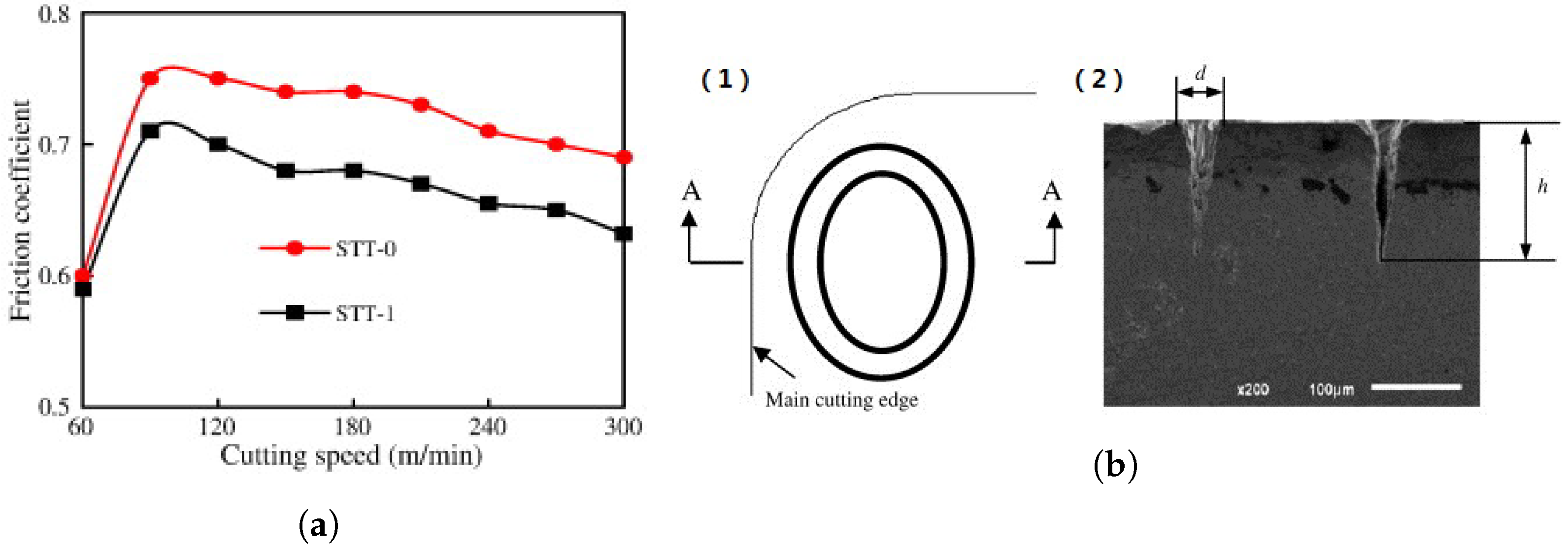
5.1.1. Dry and Wet Machining Using Textured Tools

To optimize tool efficiency during the dry cutting process, some studies integrated micro-surface textures with a solid lubrication approach. The chip moves freely over the MoS 2 -coated micro-textured cutting tools, as illustrated in Figure 13, and the solid lubricant discharges them, producing a tribo-film with weak shear strength. At the tool–chip interface, the contact length and coefficient of friction were lowered [195]. Furthermore, Sharma and Pandey found that during the machining of hardened steel, the use of hybrid textured cutting inserts solid-lubricated with CaF 2 resulted in decreased friction, specifically 4340 hardened steel [196]. Similarly, mixing a WS 2 /Zr soft coating and nano texture on the surface of the tool lessened the coefficient of friction and increased the cutting efficiency [197]. Moreover, Fu et al. [198] concentrated on a hot-pressed improved WS 2 solid lubricant. The synergistic effects of the texturing and lubricant provided outstanding anti-adhesion and anti-friction characteristics, with a WS 2 release rate reduced by 102.2% when a silane coupling compound was used. Subsequently, Li et al. [199] developed copper-based alloys coated with GuGa 2 that utilize the variation in surface tension of liquid gallium metal. The GuGa 2 grains were able to compress well during sliding operations and generate a scratched tribo-film. As a result, indium, gallium, and oxides helped minimize wear and friction on the worn surface.
Enomoto and Sugihara [155] created novel patterns of cutting tool surfaces by utilizing laser-induced period technology to increase lubrication by keeping adequate fluid film between the chip and tool, and to reduce the friction by minimizing the zone of contact between the chip and cutting tool surface. To increase the anti-adhesion effect in the machining of A5052 Al-alloy, nano/micro-texture grooves with sine wave shapes, 100–150 nm depths and 700 nm spacings were generated on the rake face of the DLC-coated WC cutting tool using a Ti-sapphire-based laser system. The cutting surface of the WC tool was prepared by utilizing a diamond slurry prior to laser irradiation to obtain a surface roughness of 40 nm (peak to valley), as seen in Figure 14. By using wet cutting, they examined the anti-adhesion of the chip at the tool/chip interface. Adhesion was effectively minimized by enhancing the cutting fluid retention on the tool surface. Three kinds of cutting tools were checked out: (1) a parallel-groove tool; (2) an orthogonal-groove tool; and (3) a typical DLC-coated polished tool. The cutting performance was evaluated using SEM and energy dispersive X-ray spectroscopy (EDX) examinations of the cutting tool’s rake face, and it was discovered that DLC-coating lowered aluminum adhesion (as shown in Figure 15a). Figure 15b,c confirm that the cutting tool surface with parallel nano or micro grooves exhibited exceptional anti-adhesive properties, surpassing that of the tool with orthogonal nano/micro-grooves. The orthogonal-groove tool experienced increased chip adhesion due to continuous interaction between chips running over the tool’s rake face, which disrupted the cutting fluid film at the tool–chip interface. With the parallel-groove tools, the chips had irregular interactions with the tool’s rake face, which prevented chip adhesion and allowed cutting fluid to be delivered from the bottoms of the grooves to the tool-chip contact surface. Another study using wet and dry cutting was published [200]. Nevertheless, during the dry cutting operation, the adherence of aluminum chips to the surface was enhanced “Figure 16a”. This method did not work and led to extraordinarily high tool wear. To resolve this concern, they created a unique coated cutting tool (TiAlN) with regularly thin parallel streaks at the surfaces. Experiments on steel surface machining revealed that the novel textured coated tool had substantially reduced tool wear [155]. On the other hand, Kawasegi et al. [201] evaluated the cutting efficiencies of textured cutting tools in different atmospheric environments and discovered that the greatest applied load minimization was achieved in an oxygenated atmosphere. They hypothesized that oxygen introduced to the interface of the tool–chip is useful for creating a film of oxide on the chip’s surface. According to Kim et al. [202], air-filled empty regions formed by micro-textures on a tool rake surface are present at the tool–chip interface during dry machining and may influence the tribological properties of the contact. These results imply that micro-textures generated on tool surfaces may potentially behave as tiny air pools during dry machining settings, improving the cutting performance.

5.1.2. Solid Lubricant-Filled Textured Tools

Many scientists have developed cutting tools involving nano- and micro-scale textures with a variety of solid lubricants, including MoS 2 [193,203,204], molybdenum- and tungsten disulfides, calcium fluoride, WS 2 [187,205,206,207], graphite, and CaF 2 [196,208], burnished or implanted into the textures. Solid lubricants produced by the texturing spread on the tool surface throughout the cutting process, causing the creation of a tribo-film with poor shear strength. As the presence of lubrication can be produced by the cutting tool itself supplying lubricants at the tool–chip contact, textured cutting tools such as these may prove to be highly effective for dry machining [203]. This tool is commonly known as the self-lubricating tool. Jianxin et al. [193] produced a cemented carbide cutting tool with different geometrical characteristics of textured surfaces by laser machining. The surface of the cutting tool was carved with elliptical, linear, and parallel grooves oriented with the main edge to produce the textured surface, as seen in Figure 17. Dry cutting tests with these rake-face textured cemented carbide-Cobalt cutting tools revealed better cutting performances over standard tools. Solid lubricant-filled grooved tools performed better in dry machining, especially at higher cutting speeds, see Figure 18a. Figure 18b displays a cross-sectional view of the surface texturing of the STT-1 tool, whereas the width (d) of the elliptical groove at the rake face is about 50 μ m, and the depth (h) of the groove is nearly four times the width (200 μ m). Due to the lubricating film having a lower shear strength at the interface of the tool–chip, which has been freed from the rake textured surfaces and splattered on the rake face of the cutting tool, it demonstrated the least cutting temperature, cutting force, and friction coefficient at the tool–chip interface in the evaluated tools. Furthermore, the shortened contact length at the tool–chip interface of a rake surface textured tool serves to decrease the physical area of contact of the chips with rake surfaces, as well as the force and temperature. The effect of surface texturing on tribological behavior and cutting tool efficiency is intimately tied to lubricant consumption in machining operations. The use of surface texturing on the tool surface can improve the lubricant performance in terms of minimizing friction and wear. Additionally, the overall impact of surface texturing and lubrication can result in a considerable decrease in the process forces and an increase in the surface quality. As a result, a thorough understanding of lubricant effects on the machining process is critical for the effective adoption of surface texturing techniques on cutting tools. To emphasize the importance of lubrication in machining, the next section will present a complete examination of the influence of lubricants on several machining parameters, such as friction, wear, process forces, and chip formation.

6. Effects of Lubricants on the Machining Process

Reduced friction, wear, and process forces are critical in machining operations, and lubricants can help with this. This section provides a comprehensive discussion of how the use of lubricants affects certain machining parameters. Temperature, pressure compatibility among cutting tools and work materials, and structural inhomogeneity of the tool materials all affect the tool’s life, with the temperature generated during cutting being the most significant tool life variable [209]. The same is present for cutting refractory hard metals, such as Inconel 718 using silicon carbide whisker-reinforced alumina cutting tools [210]. These tools may be used at significantly greater cutting speeds because of their enhanced strength and fracture toughness, which leads to greater temperatures in the tool/chip region and softening of the workpiece material. Tool failure is frequently caused by abrasion, which can result in cratering and/or flank wear, chemical interaction with the workpiece material, and/or chipping and cracking [211,212]. The machining of hard materials, such as titanium and its alloys, plays a significant role in the development of modern machining processes, such as cutting tools and coatings, with the objective of improving the machinability of these materials. The cutting tool has quicker wear as a result of the titanium’s weak thermal properties, which reduces tool life. High cutting temperatures are some of the main causes of quick tool wear and, as a result, poor machinability of titanium alloys, requiring an effective cooling technique to lower the temperature in the tool–workpiece contact areas. Researchers are investigating the use of various lubrication techniques in machining operations, such as solid lubricants [213,214,215,216], cutting fluid [217,218], or both [219]. The outcomes are encouraging, with a substantial decrease in tool wear, cutting force, dimensional inaccuracy, and surface roughness achieved by applying minimum quantity lubrication “MQL refers to the use of little amounts of cutting fluid”, particularly in lowering the temperature of the cutting zone and creating a softer chip–tool–piece interface interaction. Ricardo R. Moura et al. [219] investigated the use of a solid lubricant during the machining of Ti-6Al-4V in a turning operation. The authors conducted dry testing, lubricant tests, and tests using 20% by weight of solid lubricants, with tool life, surface roughness, cutting force, and interfacial temperature as output parameters. They found that the use of solid lubricants greatly reduced tool flank wear, a critical issue in titanium alloy machining. The experimental results showed that molybdenum disulfide outperformed graphite in turning operations by reducing tool wear, prolonging tool life, and improving surface roughness. The solid lubricant proved to be a viable option for both dry and wet turning, resulting in increased production.

6.1. The Influence of Lubricants on the Surface Properties of Cutting Materials and Tools

In metal machining, the impact of lubricants on the surfaces of cutting materials and cutting tools is a crucial factor to consider. The use of appropriate lubricants can significantly reduce wear and tear, improve the quality of machined parts, and enhance the performance of cutting tools. Many studies have been conducted to investigate the effects of lubricants on the surface properties of cutting materials and tools, with varying degrees of success. Kumar et al. [220] investigated the surface roughness of AISI 304 steel throughout turning using alumina nanofluid and hybrid nanoparticle lubricants. By combining alumina-based cutting fluid with multi-walled carbon nanotube (MWCNT) nanoparticles at various volumetric concentrations, a hybrid nano-cutting fluid was created. The authors discovered that using hybrid lubricant produced the lowest surface roughness and enhanced surface quality. The lowest coefficient of friction was achieved by utilizing 1.25 vol% Al-MWCNT hybrid nanofluid, alumina nanofluid, and a much lower base fluid. In order to machine harden carbon steels, Wang et al. [73] used nano-sized CaF 2 as a solid lubricant for tungsten–titanium carbide (WTC) composite cutting tools. This resulted in a significant decrease in cutting force, temperature, and surface roughness of the workpiece while increasing the fracture toughness of the WTC composite tools by 13%. As seen in Figure 19, ecological cooling technologies reduce crater depth by approximately 35% when compared to dry machining. The creation of a continuous chip in the cutting area increases the intensity of abrasive wear on the rake face of the cutting tool during dry machining. The chemical reaction between the rake face of a tool insert and the heated chip is the primary reason. Stuck material during machining was also discovered in a study of a cutting tool under dry cutting settings. As a result of greater temperatures in the tooltip, this might lead to a higher intensity of adhesion wear.

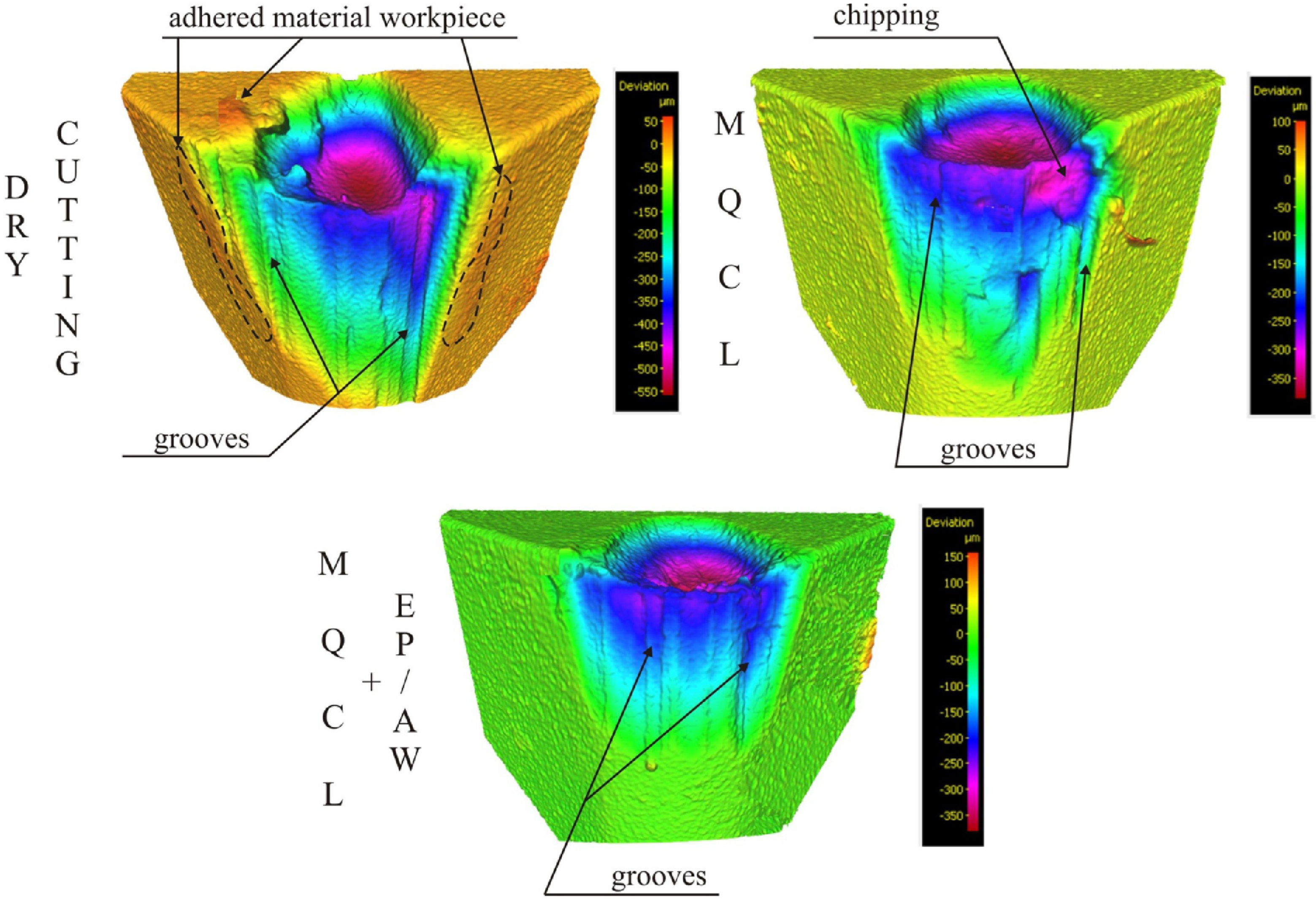
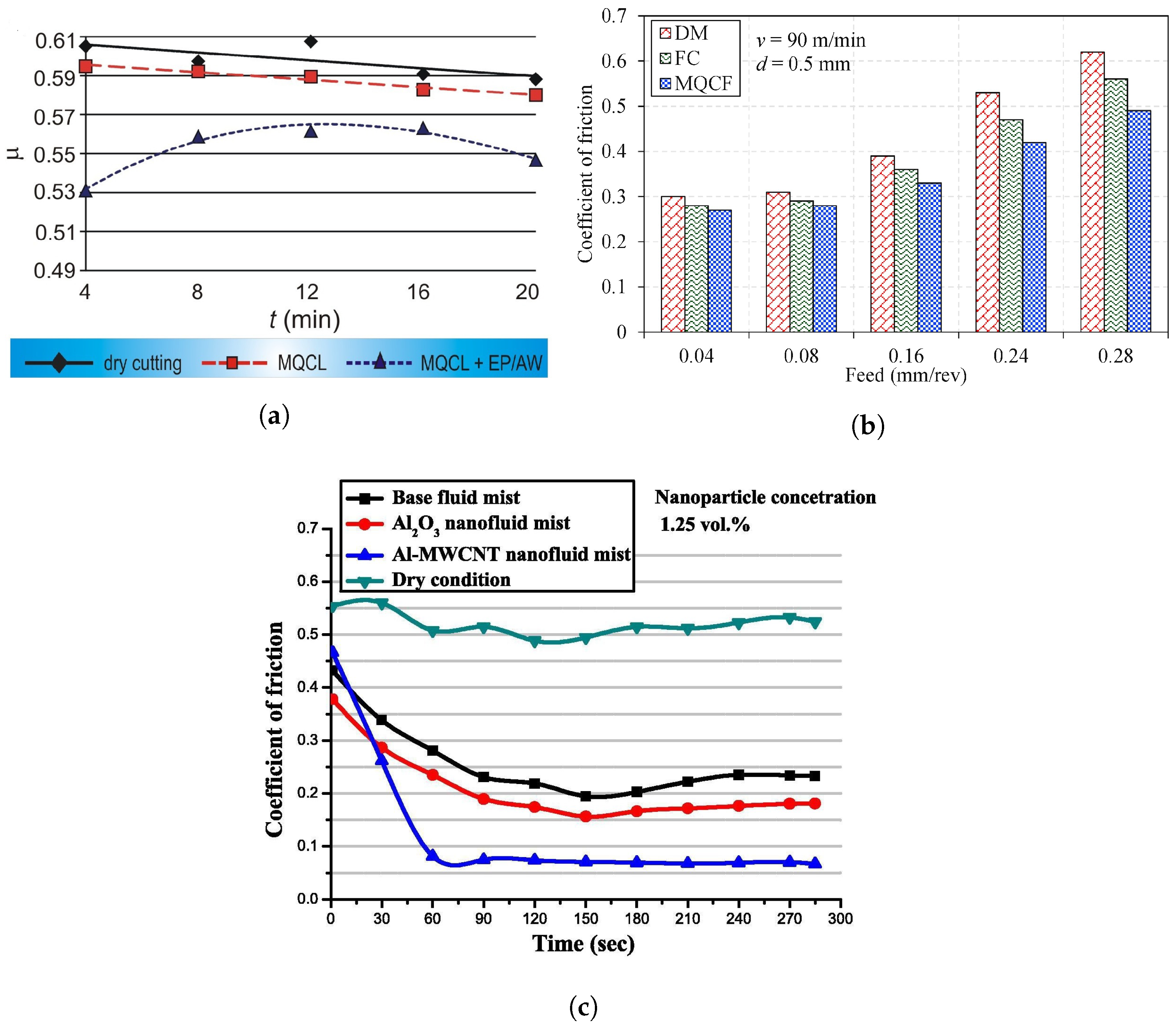
6.2. The Effect of Cooling/Lubrication on Friction Behavior

Friction is a significant issue in machining operations because it increases cutting forces, tool wear, and temperature, resulting in poor surface quality, longer cycle times, and shorter tool life. Lubricants can minimize machining friction by producing a thin coating between the tool and the workpiece, minimizing actual metal-to-metal interaction [195,197]. Various lubricants, including oil-based, water-based, and solid lubricants, have proven to be helpful in decreasing friction in machining. The lubricant type and concentration, as well as the machining parameters, all have a substantial influence on friction reduction in machining [14,22].
Numerous innovative lubrication and cooling techniques for sustainable machining technologies have been developed to reduce the negative impacts associated with the coolant. The minimal quantity lubrication (MQL) technique is commonly utilized. As seen in Figure 20, the MQL approach lowered the coefficient of friction when contrasted with dry cutting since the tool–chip contact interval was reduced [222]. Comparative investigations for various cooling settings (dry, MQL, and high-pressure air) revealed that MQL was much more useful for reducing friction at slower cutting speeds [223,224]. Until now, the behavior of friction was greatly dependent on the lubricant types. The use of MQL + EP/AW caused the creation of a thin friction layer on the surface of the cutting tool, decreasing the coefficient of friction of the rake face by 6.2%–15.4% when compared to MQL alone [221]. Many studies have evaluated the impacts of different nano-additives on lubrication. The hybrid cutting nanofluids HN-GCF-0.3M were created by combining molybdenum disulfide (MoS 2 ) and calcium fluoride (CaF 2 ) solid lubricants, which lowered the coefficient of friction by 11% [225]. Many studies additionally discovered that the friction layer created by Al 2 O 3 nanofluids lowered the coefficient of friction during sliding when compared to Ag nanofluids and that combining multi-walled carbon nanotubes with Al 2 O 3 nanoparticles boosted the influence of friction reduction [226]. According to Figure 20c, the Al-MWCNT lubricant has the lowest friction coefficient, followed by alumina nanofluid. Its decreased coefficient of friction value lowered the friction force and, therefore, the cutting loads [220]. Moreover, using graphene nanosheets (GPL) as an additive lowered the coefficient of friction when using the electrostatic MQL approach. This was linked to increased GPL droplet penetration and deposition in the interfacial friction region [227].

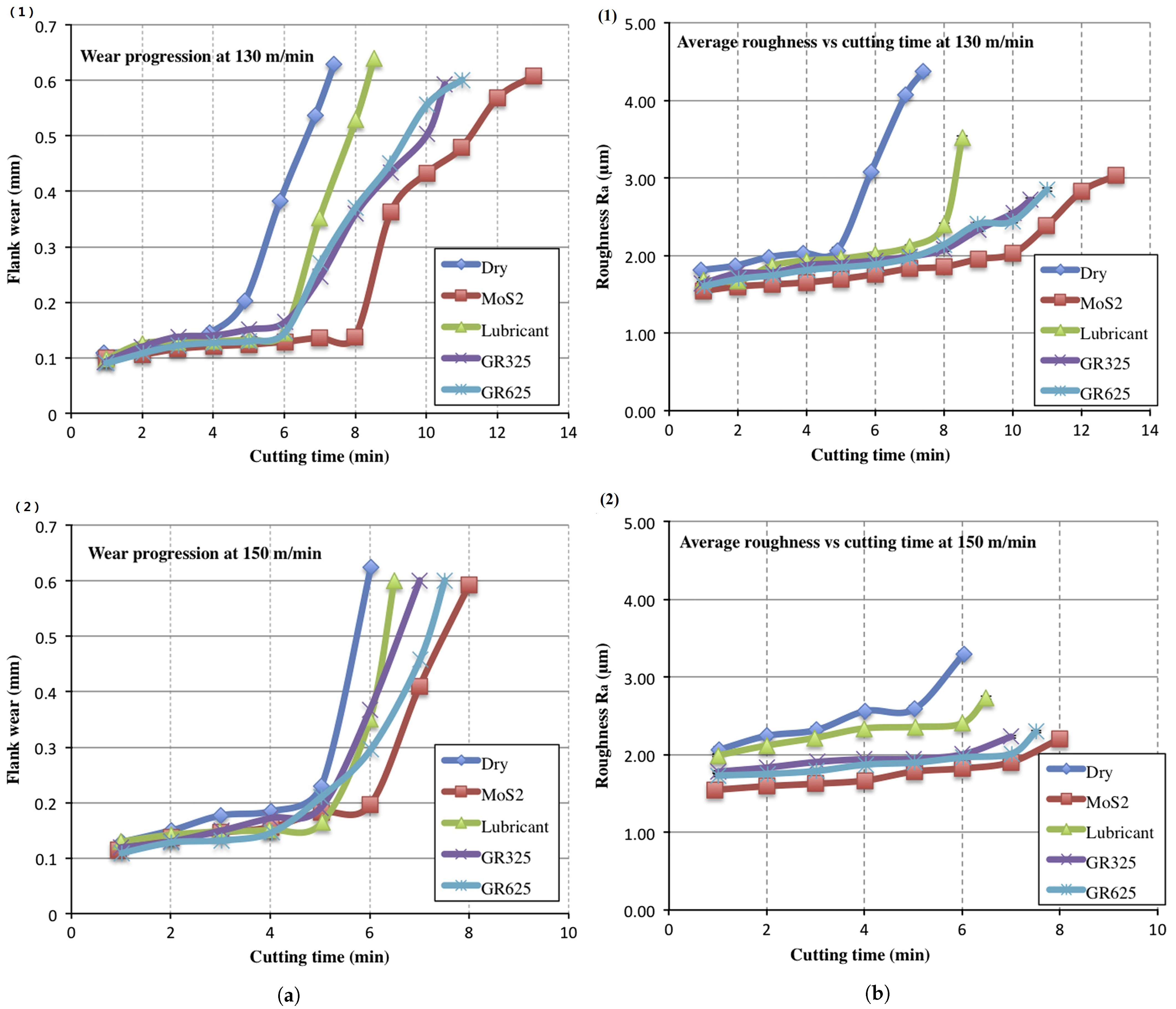
6.3. The Relative Influence of Lubricants on the Wear Property

Wear is an essential factor in machining operations because it may reduce the tool life and increase cutting forces. Lubricants used in machining may minimize wear by producing a protective layer on the surface of the tool, which could reduce abrasive and adhesive wear [110]. The kind and amount of lubricant, in addition to the cutting parameters, all have a substantial influence on the wear behavior in metalworking. Some lubricants may significantly boost wear under specific cutting circumstances; therefore, it is critical to select the correct lubricant for every machining operation [21,22]. De Portu et al. [228] studied the behavior of Al 2 O 3 -Mo and Al 2 O 3 -Nb particulate composites with varying quantities of secondary phases and particle sizes. The composites were evaluated on a disc-on-pin apparatus with loads ranging from 10 to 150 N at a sliding speed of 0.5 ms 1 with WC as the counterface material. For all composites, the friction coefficient lowered with higher applied stresses. The rate of decline was higher (up to 50 N) and slower as the applied load increased. There was no noticeable difference among the materials. The observed property of the debris film was related to the decrease in friction. Greater contact forces created greater temperatures, and the metal particles contained in the debris rapidly oxidized, improving the lubricating characteristics of the films.
Maximum flank wear vs. cutting time is shown in Figure 21a [219] for various cooling/lubrication parameters. Once that tool entered the high wear rate region at 130 m/min (Figure 21(a1)), the flank wear rose substantially with the cutting time under dry conditions for cutting after 4 min. This increased wear rate region will not occur for at least 6 min under MQL circumstances. While utilizing MoS 2 , this takes approximately 8 min for the tool to actually enter this region. However, at 150 m/min (Figure 21(a2)), MoS 2 became the most effective lubricant in improving the tool life. MoS 2 ’s higher cooling and lubricating efficiency can really be attributed to the extended tool life. When just the cutting fluid was used, tool wear was greater than when solid lubricants were used.
Furthermore, lubricant utilization has a favorable influence on the modification of workpiece surface roughness. As shown in Figure 21b, raising the cutting speed led to a decline in surface roughness. The reduced surface roughness values obtained by molybdenum disulfide could be attributable to its superior adherence to graphite [229]. Across several areas, namely surface roughness, the efficiency of solid lubricant-supported machining surpasses that of both dry and wet machining [214,215,219]. Trent and Wright [230] suggested that cemented carbide tool failure was caused by the dispersion of metal and carbon atoms through the workpiece, leading to a crater in the cutting tool and a shorter life. Prolonged cutting times have been associated with this wear via diffusion, and temperatures between 700 °C and 900 °C are strong enough for diffusion to occur significantly. Diffusion rates grow significantly with the temperature, often doubling for every 20 °C increase. The diffusion rate of wear is influenced by the metallurgical interaction between the tool and the work material, and it is more important for WC tools than for high-speed steel (HSS) tools. Moving on, as indicated in Figure 22, a build-up edge may form on the surface of the cutting tool due to wear between both the workpiece and the cutting tool, whereas lubricants may reduce the formation. The small hardness of the composite materials is considered to cause the adhesion of the soft matrix to the tool, owing to an inadequate lubricating action. Because of the absence of tribological performance enhancements in other conditions, the dry environment is already hungry for material adhesion [231].

6.4. The Effects of Cooling and Lubrication on the Cutting Forces and Chip Formation

Lastly, the use of lubricants during machining might affect chip formation. Lubricants can lower cutting forces and temperatures, resulting in smaller and more uniform chips, where friction behaviors at the tool–chip interface cause a gradient distribution of thermomechanical stresses, which have major impacts on the chip formation process. S. Zhang et al. [233] investigated tool wear and cutting forces during end-milling of Inconel 718 using coated cutting tools with both dry cutting and MQCL using biodegradable vegetable oil. The values of the major cutting force components are substantially lower under MQCL cutting conditions than under the dry cutting process, as shown in Figure 23a. The decrease in cutting forces suggests that the MQCL approach was successful in lowering cutting forces and, thereby, conserving energy. Similarly, other researchers studied the effects of different coolants on the cutting force generated during the cutting process [234,235]. When these coolants are added in different concentrations, the cutting force decreases gradually, as shown in Figure 23b,c. According to research, the thermomechanical forces caused by cutting friction in the shear zone are the primary driving forces in the growth of the plastic behaviors of the chip bottom [236]. This can lead to better surface quality and shorter cycle times. Furthermore, at higher cutting speeds, the chip bottom contact pattern modifies from constant sliding to sticking–sliding. Sticking–sliding on the chip bottom has been linked to thermodynamic instability and dynamic interaction generated by nonlinear friction and shear dissipation [237,238]. In machining, the kind and concentration of the lubricant, as well as the cutting conditions, all have substantial influences on chip formation. Chip morphology, in some ways, indicates the excellence of machining processes, because distinguishing properties, such as color, geometry, and serration are essential outputs [239]. The main reason would be that a targeted chip shape is connected with acceptable surface morphology as well as tool wear texture. A further essential factor of chip morphology is its capacity to efficiently discharge the ambient heat near the cutting area [240]. As a result, quick and successful chip removal ensures that thermally generated distortions on the subsurface and the surfaces of cutting tools and workpieces are significantly reduced. Furthermore, when evaluating the machined component in its entirety, periodic chip formation is of great relevance for obtaining totally precise surface integrity [241]. As seen in Figure 24a [232], cryogenic coolant-assisted and dry media appear to be identical because they include identical dimensional chips. It is clear that a sub-zero flow helps to cool the main matrix and reinforcement of Cu-based hybrid composites at various rates. During composite cutting and removal of the material, a distinct separation process occurs, causing rupturing and (in some cases) cutting. Cryogenics and MQL oil’s cooling and lubricating processes provide superior tribological environments for chip breakability, which may be described as self-breakage [242]. Radoslaw W. Maruda et al. [221] investigated chip morphology based on several types of lubricants at various times and cutting speeds and discovered that the most favorable chip in the full-time range can be achieved while cooling under the MQCL + EP/AW scenarios, as shown in Figure 24b. Using this cooling approach, an arch-shaped loose chip was formed practically throughout the whole range of the cutting tool wear; a helical open short chip was obtained just after 8 min of the cutting tool running. These chips are readily removed from the cutting area and do no harm the workpiece surface. As illustrated in Figure 25, when the tool wear increased, the contact surface of the chip became rougher with narrow grooves, whereas the sizes of the gaps and fractures developed owing to the plowing and rubbing action. The micro-mill wore down gradually because more material was cut and the cutting temperature increased. As a result, friction and extrusion between the rake face and the chip caused significant plastic deformation of the chip at high temperatures. Furthermore, because of the intense plastic deformation, the surface of the chip boundaries was produced in a free condition, potentially creating micro-cracks along the propagation [243].
In conclusion, the effects of lubricants on friction, wear behavior, process forces, and chip formation in machining are complex and highly dependent on the type and concentration of the lubricant, as well as the cutting conditions. It is important to choose the appropriate lubricant for each machining process to achieve the desired results. Finite element analysis is a useful technique for investigating the intricate interactions between the tool and the workpiece throughout the machining process, particularly when cutting the tool indentation. The cutting tool’s deformation behavior is a significant characteristic that impacts the quality of the machined surface and tool life. As a result, in the next section, we will review the finite element formulations and the finite element cutting tool indentation.

7. Finite Element Analysis of the Machining Process of the Cutting Tool

The machining process is a complicated phenomenon that is primarily determined by the friction between the workpiece and the cutting tool, as well as the adiabatic shearing, cutting temperature, stresses, strains, and strain rate. Previous research advises using simulations and the finite element modeling technique “FEM” to comprehend the intricate phenomena of the machining method in an easy and economical way. These models may be expressively categorized into experimental, analytical, computational, empirical, and mixed kinds [244,245]. The advancement of machining processes, from traditional to ultra-precision micro/nano dimensions, is heavily reliant on these forecasting analytics. The cutting process has been qualitatively and quantitatively analyzed using the finite element analysis (FEA) to understand chip morphologies, stresses, strains, cutting forces, temperatures, and other exogenous variables. A number of analyses are used in the FEA machining investigations, including machining parameters and conditions [223,246,247,248,249,250,251,252], tool geometry [253,254,255,256,257], workpiece orientation [258,259], tool wear measurements [255,260,261], chip separation criteria [262,263,264,265], and meshing and remeshing techniques [266,267,268,269]. Finite element approaches have been utilized in several studies to model the formation of radial cracks in cutting tool inserts due to Vickers [270,271,272], Berkovich [273], or Brinell [274] indentations in cutting tool inserts.

7.1. Finite Element Formulations

The Lagrangian, Eulerian, and arbitrarily Lagrangian–Eulerian (ALE) techniques have been employed for machining simulations, using issue domains dependent on the dynamics, the kind of continuum, and the deformation scaling. Regardless of the data element, the number of components inside the unit area relates to the density of the mesh. While mesh density is critical for obtaining optimum chip creation and superior outcomes, adopting similar mesh densities throughout the domain may result in greater computational costs. As a consequence, an improved mesh should be utilized in and around the chip generation region, where a coarser mesh may be employed in the rest of the model [275].

7.1.1. Lagrangian Approach

The Lagrangian technique has been frequently used in cutting simulations due to its numerical precision [276,277,278]. The Lagrangian technique keeps the mesh’s elements and nodes connected to the material, making the application of boundary constraints and monitoring free surfaces simple. The Lagrangian mesh models the underlying material’s deformation while keeping the location of the mesh nodes compared to the material points constant. Klamecki was the first to use it in 1973 [279]. One disadvantage of the Lagrangian technique is the significant mesh distortion caused by the large deformations in cutting models. Extreme element distortion at the tool–chip contact causes convergence problems causing the simulation to terminate. To model chip creation, nodes must be separated using chip separation methods or adaptive meshing. When using cutting tools with a negative rake angle, the node separation techniques suffer from performance failure and round-edged tools. The Lagrangian technique is further divided into mesh-free and mesh-based approaches depending on the interrelationship of nodes.

7.1.2. Eulerian Formulation

Metal machining simulations have used the Eulerian technique. The mesh remains stationary in space in the Eulerian formulation, and the mesh allows materials to pass along while cutting the distortion. Free boundary and interface conditions are challenging to describe because mesh nodes and intrinsic material boundaries might not even coincide. The chip shape must be predetermined while employing the Eulerian technique during cutting simulations. Usui et al. [280,281,282] pioneered the Eulerian technique in cutting simulation. Following that, several researchers modified the model to improve its accuracy, assess the final chip shape and tool–chip contact length, and optimize many other machining factors [262,283,284,285]. To model the cutting process, the Eulerian technique utilizes a set reference frame and a preset chip shape to generate an answer to mesh distortion. The shape of a chip influences additional machining variables, such as temperature, friction, and cutting forces; hence, improperly designed chip geometry can lead to misleading results. Regarding fluid simulators or operations with clearly defined material boundaries, the Eulerian method is recommended. The method has been used effectively in forging and extrusion procedures [286]. Because the Eulerian technique does not really suffer from mesh distortion difficulties and, hence, does not require remeshing, it takes priority over the Lagrangian approach. Additionally, it offers instant steady-state results without requiring a change from the incipient to the steady-state condition, resulting in more precise and substantially lower expensive approaches.

7.1.3. Arbitrary Lagrangian–Eulerian Formulation

The arbitrary Lagrangian–Eulerian (ALE) method takes advantage of the features of both conventional Lagrangian and Eulerian formulations. ALE decreases mesh distortion by enabling boundary nodes to correspond with material boundaries when modifying inner nodes. ALE retains the Lagrangian capacity of limited mesh motions at free boundaries while retaining the Eulerian performance in cutting simulations throughout chip generation in the extreme deformation zone. Using both techniques in the ALE formulation overcomes the problem of mesh distortion and utilizes spontaneous chip generation without pre-defining chip geometry. The ALE technique is implemented by using a user-defined mesh regularization or mesh adaption technique [287]. By continually developing the node coordinates with displacement or velocity parameters, mesh regularization algorithms ensure that the mesh remains uniform under severe deformation. The ALE methodology may be used to estimate a problem solution range either by concurrently calculating all non-symmetric equations or by utilizing the ALE operator split technique to dissociate Lagrangian equations [288]. The ALE with mesh adaptation includes the targeted mesh refining and remeshing inside the extreme deformation zone. The model results show that when using the ALE formulation with Eulerian bounds, this friction criterion at the tool–chip contact has no substantial impact on the outcome measure [289]. A predetermined chip shape arbitrary Lagrangian–Eulerian formulation has also been investigated. Movahhedy et al. [265,290] and Olovsson et al. [291] approximated ALE in two-dimensional cutting method simulation models and characterized this approach does not require the use of almost any chips separating parameters and that the outcomes could be expected to be more robust than with the Eulerian technique alone. The ALE formulation is often used in numerical simulation investigations of tool wear [292,293,294,295].
Table 3 lists a summary of the main benefits and drawbacks of the Eulerian approach, Lagrangian approach, and arbitrary Lagrangian–Eulerian (ALE) approach.

7.2. Finite Element Indentation of Cutting Tool

The FEM is utilized to investigate the material deformation mechanism in more depth, and it is an efficient method for investigating the indentation operation [297,298] and determining the relation between both the basic mechanical performance test and hardness. FEM creates the relation between strain and hardness [299] and the relation between effective stress and hardness [300]. The uniaxial compression test and hardness test are also utilized to assess plastic deformation resistance. This is critical for connecting them using FEM [301], which has already been effectively implemented in ambient temperature environments [299,302].

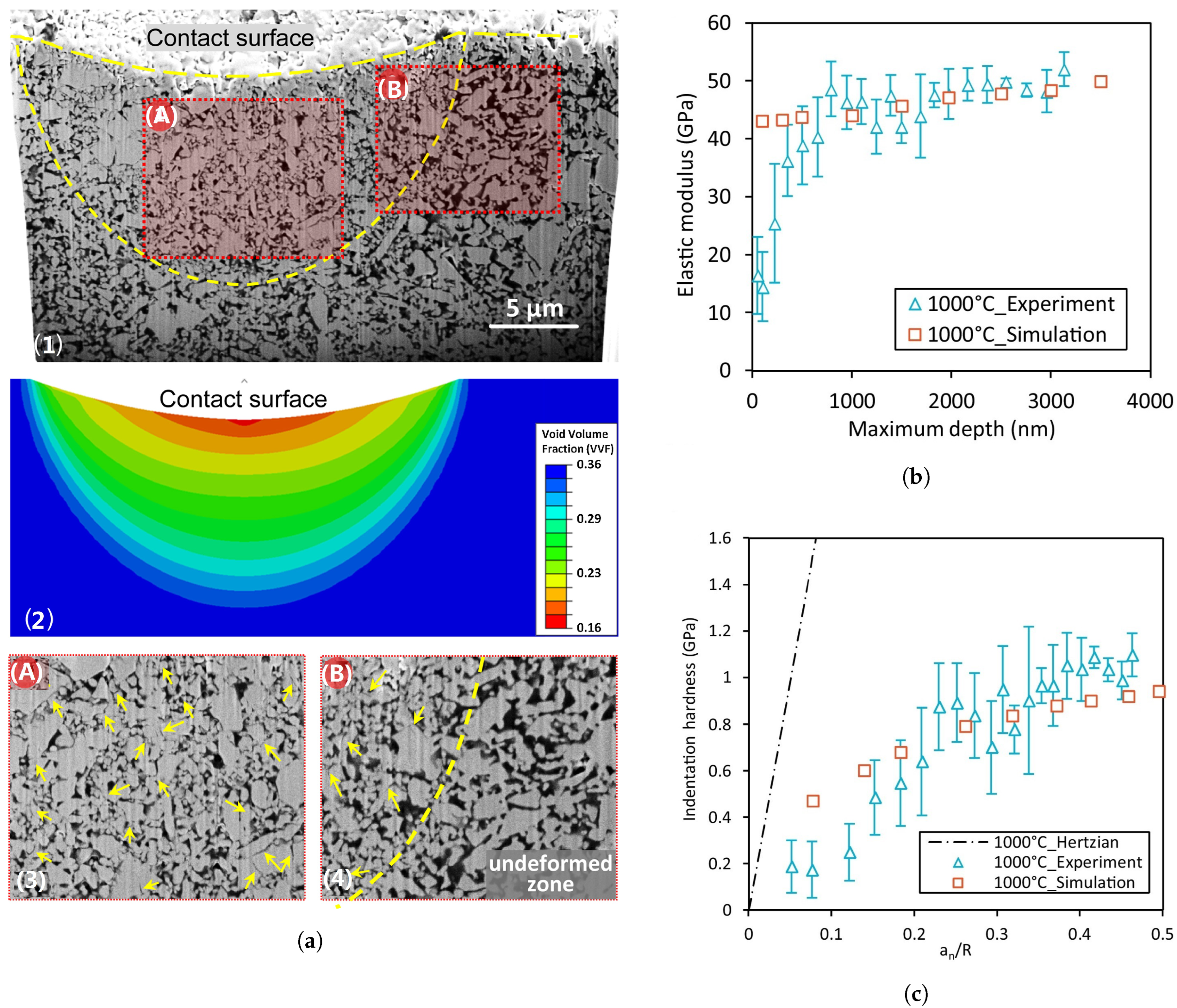
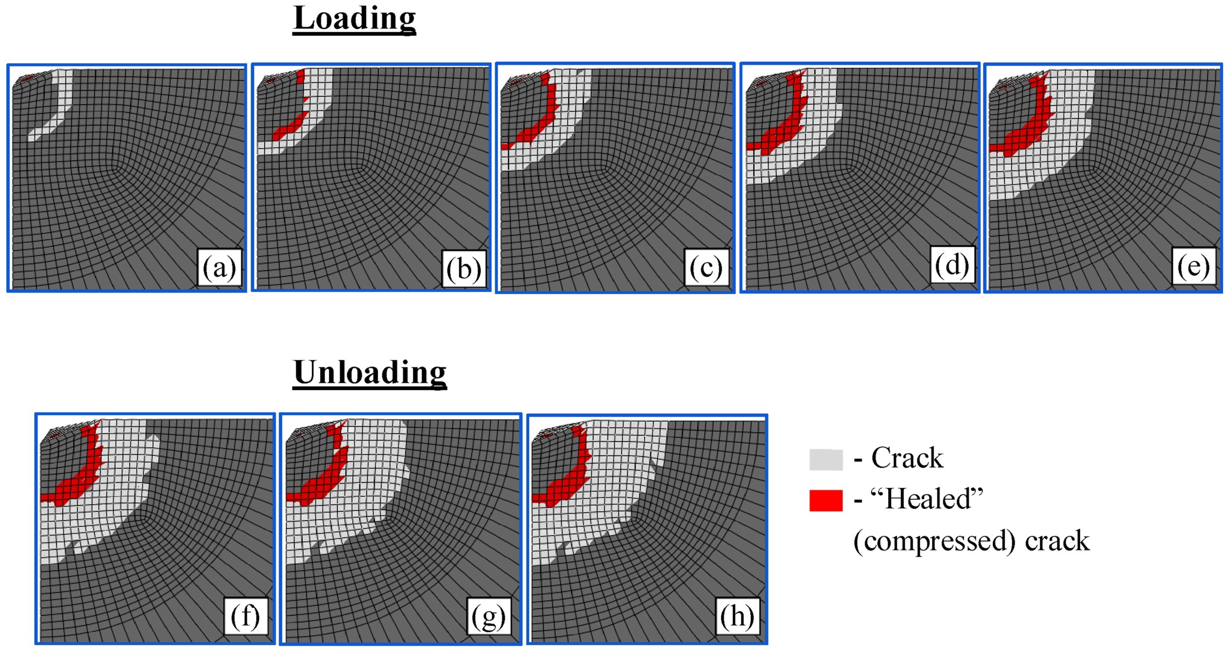
7.2.1. Spherical Indentation

Spherical indentation is a method for determining the hardness of cutting tool inserts. Zhangwei Chen et al. [274] developed a mixed experimental and numerical technique for assessing elastic and plastic deformation of porous bulk ceramic material under spherical indentation. After sintering at high temperatures between 900 and 1200 °C, tests of indentation were carried out on porous bulk ceramic specimens. In FEM simulations, the Gurson model was employed to simulate the densification of the porous material in the plastic zone underneath the indenter. The yield condition is stated by the equation below [303,304]:
Φ = q σ y d 2 + f cosh 3 P 2 σ y d 1 f 2 = 0
where f is the function of the porosity, the dense matrix material’s yield stress is σ y d . At f = 0 (i.e., completely dense), the von Mises yield condition simplifies the Gurson yield condition, which is q = σ y d . They discovered that choosing a friction coefficient of 0 or 1 had no discernible influence on the load vs. depth curves, as stated in a previous FEM literature survey, because of the insignificant influence of the accurate coefficient of friction on the findings [305,306,307]. They also discovered that, using actual tests and FE simulation “Figure 26”, sintered specimens at 1000 °C exhibited the highest indentation resistance. The indented specimens showed no cracking, as shown in Figure 26a. Furthermore, there was no evidence of a pileup near the indentation mark’s perimeter. The densification zones, according to their calculations, have a hemispherical structure with a diameter equal to the contact diameter. The distorted zones show evidence of early pore compression; as indicated by the arrows in the illustration, interparticle and intra-particle collapses occur. Figure 26b,c demonstrate that the elastic modulus and indentation hardness measured by both simulations and tests for sintered materials at elevated temperatures reach 1000 °C. They also show that their method allows the uniaxial yield stress of porous material to be calculated using indentation hardness; the hardness is roughly 1.7 times the yield stress for the type of ceramic. However, the spherical indenter is not suitable for nano-indentation because of the relatively large fully plastic zone under the indenter surface [308,309,310,311]. Spherical indentation of porous ceramics with the sphere radius is as follows [312]:
H n = P m a x π ( 2 R i h C h C 2 ) , h c = h m a x 0.75 P m a x S .
where H n is the indentation hardness “GPa”, P m a x is the maximum applied load “N”, R i is the indenter radius “ μ m ”, h c is the contact depth “ μ m ”, h m a x is the maximum indentation depth “ μ m ”, S is the contact stiffness calculated as the slope of the initial unloading curve at the maximum load “ N m 1 ”.

7.2.2. Vickers Indentation

The hardness property of the cutting tool can be measured by pushing a hard indenter into the surface, where a Vickers indenter, usually made of diamond, can be used to determine the scratch resistance of cermets. A typical hardness test is that of Vickers, the geometry of which is shown below. The (diamond) indenter is a right pyramid with a square base and an angle of 136° between its opposing sides. In the ideal case of “no cracks”, this is the Vickers hardness formula [313]:
H v = 0.1891 F d 2
where F is the normal force (N), and d is the diagonal length of the indentation whenever the materials are about to collapse (mm). Cracks occurred at the indentation point of both brittle and hard materials since the force used in the hardness measurement was gradually raised. Because the crack opening angle α was often tiny, the approximate computation shown below might be conducted:
H v = 0.1891 F d + 4 l tan α 2 2
where F is the applied normal force (N), l is the crack length (mm), d is the indentation diagonal length before cracking (mm), the Vickers hardness after breaking is denoted by H v , α is the angle of the crack opening (◦), and its size is dependent on the material characteristics. Varying materials obtain various α values, which can be checked by providing a significant force. As α increases, the material’s brittleness and fracture opening angle also increase. Kadina et al. [270] provided two approaches for simulating radial crack formation: one based on fracture mechanics and the other on the tensile stress criteria. Plastic deformation causes fracture growth in Vickers indentation, which can occur in limited quantities even in brittle materials, such as Si 3 N 4 ceramics. Because of a lack of understanding of the plasticity of Si 3 N 4 , the DP model was selected since it is more versatile than standard plasticity and is widely used for non-metallic materials. The fracture mechanics-based simulation outcomes in terms of surface crack development were compared to the experimentally measured length, which was easily recognized. When the DP effect decreases and the plastic behavior of Si 3 N 4 converges to classical plasticity, the fracture size is overestimated, most likely owing to the small-scale plasticity in the indentation and the high quality of the Si 3 N 4 ceramics, which are used for hybrid bearings. The high densification levels and fine structures of these ceramics may prevent the presence of heterogeneity. The following equation was used to calculate the toughness of indentation fractures [314,315]:
K I C = 0.016 P C R 3 / 2 E H 1 / 2
where C R is the surface crack length, P is the indentation load “ k g f ”, H is the hardness, E is the elastic modulus GPa, and K I C is the toughness “MPa m 1 / 2 ”. Figure 27 shows the findings of a stress criterion-based model that simulates the propagation of a radial fracture during each loading–unloading process.
To simulate the formation and propagation of cracks in the indentation region during microhardness tests, Luo et al. [316] proposed a model for the size of the indentation effect–crack propagation for both brittle and hard materials. The findings demonstrated that the crack opening angle and crack length were critical characteristics influencing the size parameters. The larger the extent of the fracture, the greater the crack opening angle and the more visible the size impact. Throughout microhardness testing, Abaqus finite element software was used to predict the formation and spreading of fractures in the deformation zone of ultrafine-grained Si 2 N 2 O-Si 3 N 4 ceramics. In the indentation zone with cracks, the distributions of the stress field, strain field, and displacement field were investigated.
Figure 27. Crack propagation when loading and unloading changing from (ae) during loading and from (eh) while unloading. Reprinted from [270], CC BY-NC-ND 4.0.
Lubricants 11 00122 g027
In conclusion, this review article offered a comprehensive review of the topic at hand. The study and material offered have shed light on numerous aspects of the topic, and the results have the potential to considerably contribute to the current body of knowledge. This review article is intended to be a valuable source of information for academics and scholars in this field, and promote more research.

8. Conclusions

A cermet is a type of material that combines the strengths of metallic binders and ceramic phases while minimizing the drawbacks of both. The historical evolution of ceramic was clarified. Cermets were categorized and investigated according to the ceramic components. The effects of additions, binders, and contents on different tribological and mechanical characteristics were discussed, as well as the applicability and significance of every ceramic system. Different types of production methods for the manufacturing of cermets were described, and the impacts of processing routes and processing factors were explored by researchers. The ultimate characteristics of the ceramic system are influenced by a number of aspects. A good selection of material compositions and processes guarantees that the tribological and cutting performances are met. Cermet synthesis offers several challenges, and several academics are working to improve the current processing methods and create novel approaches. Complex techniques with great final characteristics help to tackle the ingrained problems of producing particles containing ceramic and metal phases. The cutting tool and its quality are two of the most critical challenges in machining. Transition elements in sulfide forms can reduce the coefficients of friction and wear rates of coated tools due to their self-lubricating properties. In addition, soft metal lubricants (Ag, Cu, Ni, etc.) as solid lubricants enhance the tribological and toughness properties of coated tools. Moreover, lubricant coatings utilizing solid lubricant additives on the contact surfaces cause an increase in the anti-wear and anti-friction properties of coated film at high temperatures. Whereas, oxidation and decomposition of solid lubricants are the main drawbacks of the utilization of coating layers, whereas in situ fabrication techniques can be used to overcome this problem. When producing tools, it is often necessary to have high hardness and superior mechanical properties, along with adequate tool life and performance, while considering economic factors and tool fabrication procedures. Dry machining capabilities are also desirable. Taking these factors into consideration, ceramic and cermet tools for cutting have already been extensively researched; tribological and mechanical characteristics have been evaluated and further investigated to achieve the best ceramic tool properties and improve cutting tool efficiency; various techniques of ceramics fabrication have also been reviewed. Finally, finite element analyses on cutting processes and indentation tests have been addressed.
To summarize:
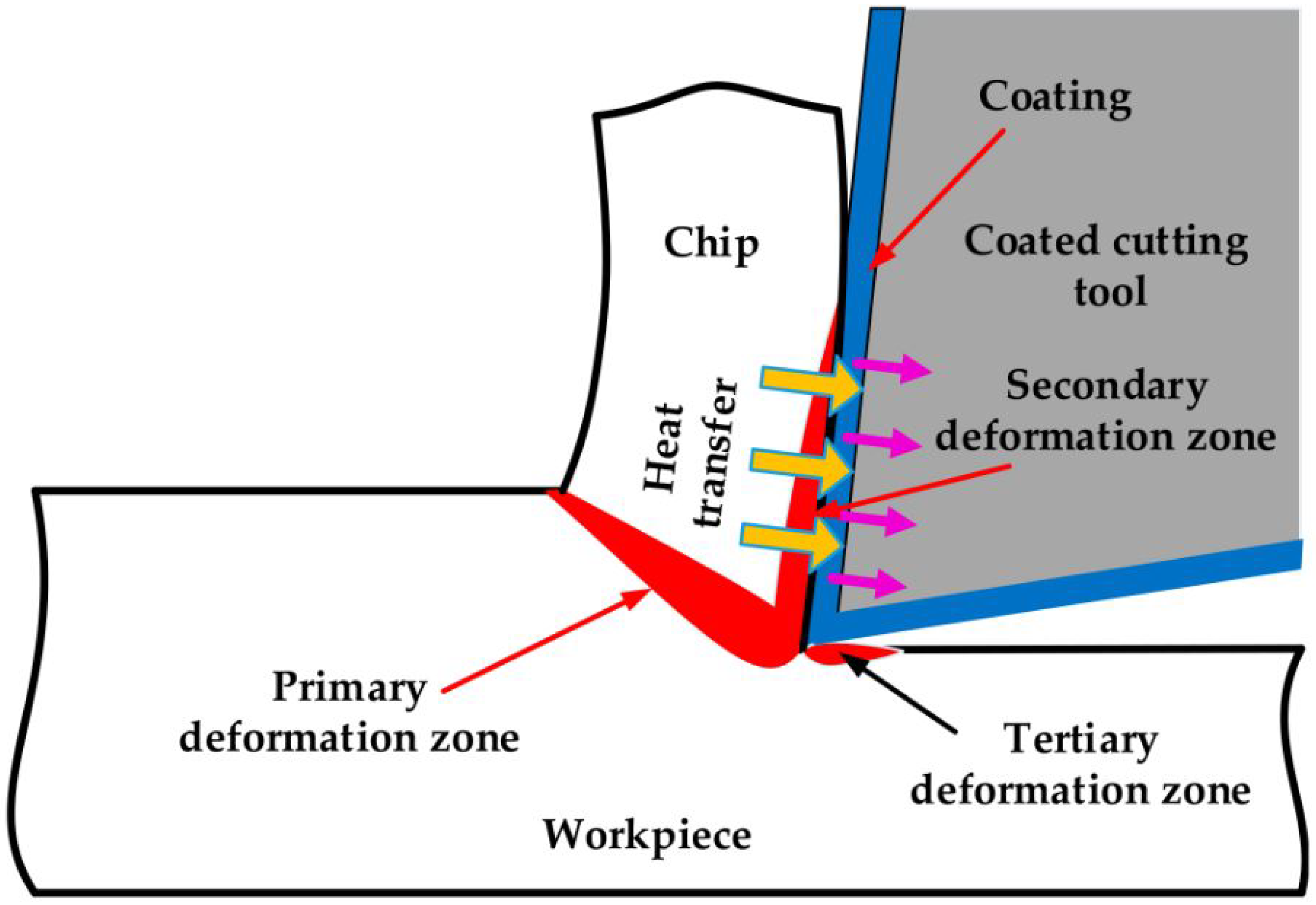
  • One of the most common cutting tool failures occurs when there is a rapid temperature rise in the contact zone between the cutting tool and workpiece throughout higher cutting speed operations (from 50 up to 300 m/min), where liquid lubrication is incapable of sustaining excessive deformation in the machining zone, resulting in tool failure. By using a solid lubricant, recent technologies have attempted to reduce the frictional heating region and energy consumption during high-speed marching.
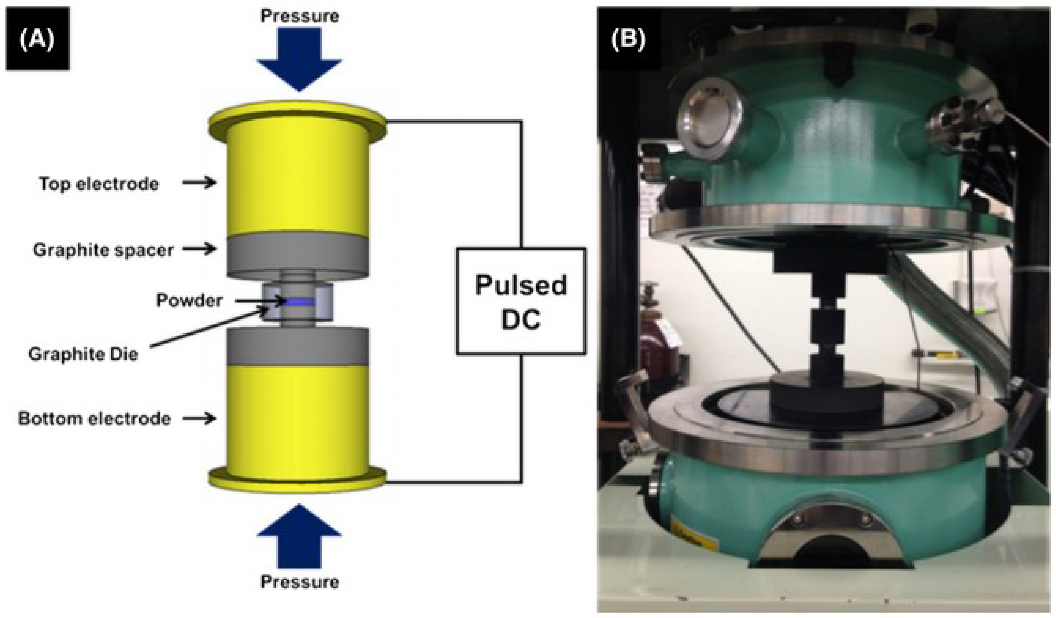
  • Both pressureless sintering (vacuum or nitrogen atmosphere) and hot-pressing are the preferred methods of producing cutting tools. Contactless techniques, such as microwaves as well as certain SPS sintering, are, nevertheless, being aggressively pursued.
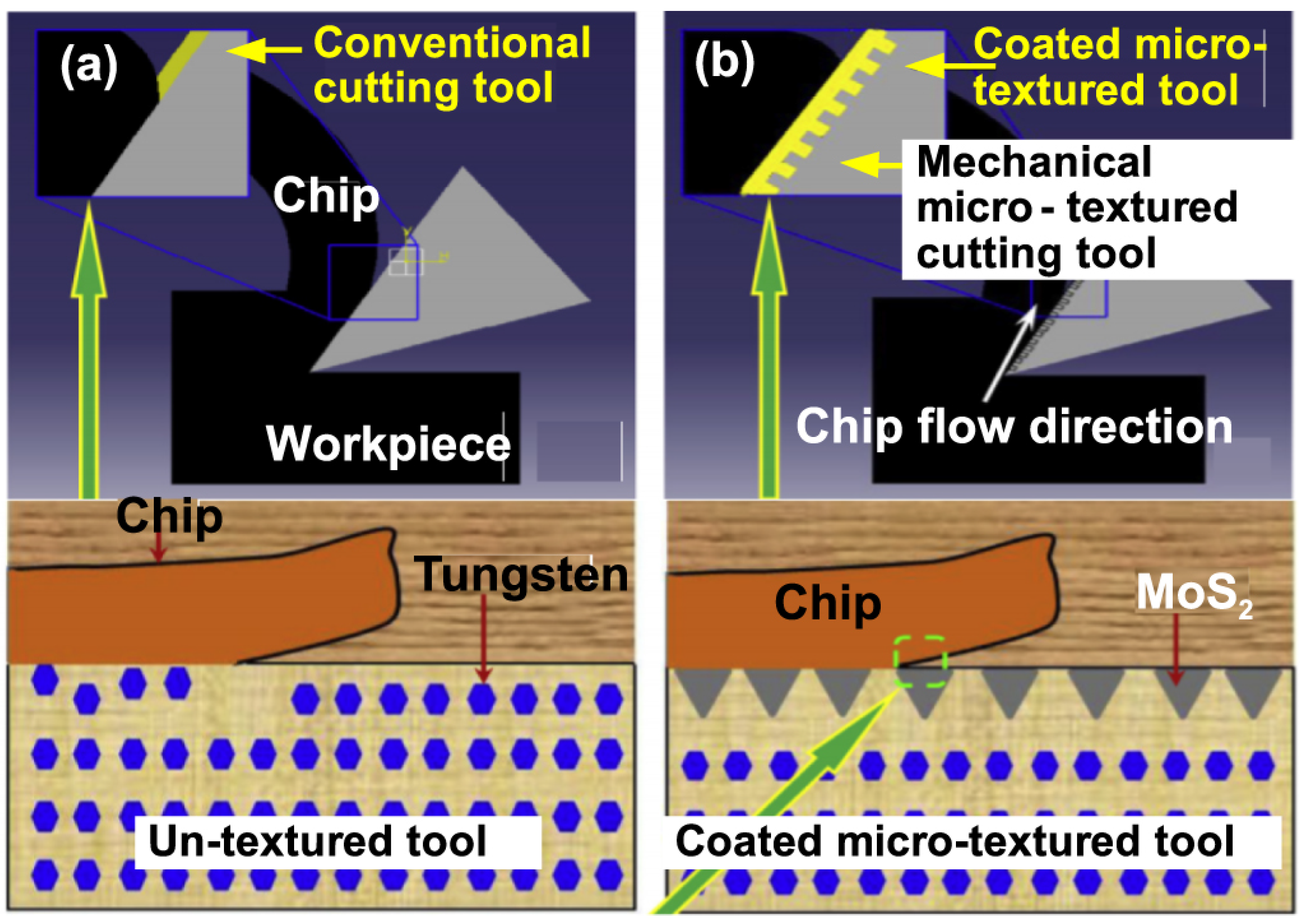
  • Under dry cutting conditions, solid lubricants and surface texturing have been observed to significantly reduce friction and wear. These two methods have been merged in recent decades to maximize the benefits of each for higher tribological performance.
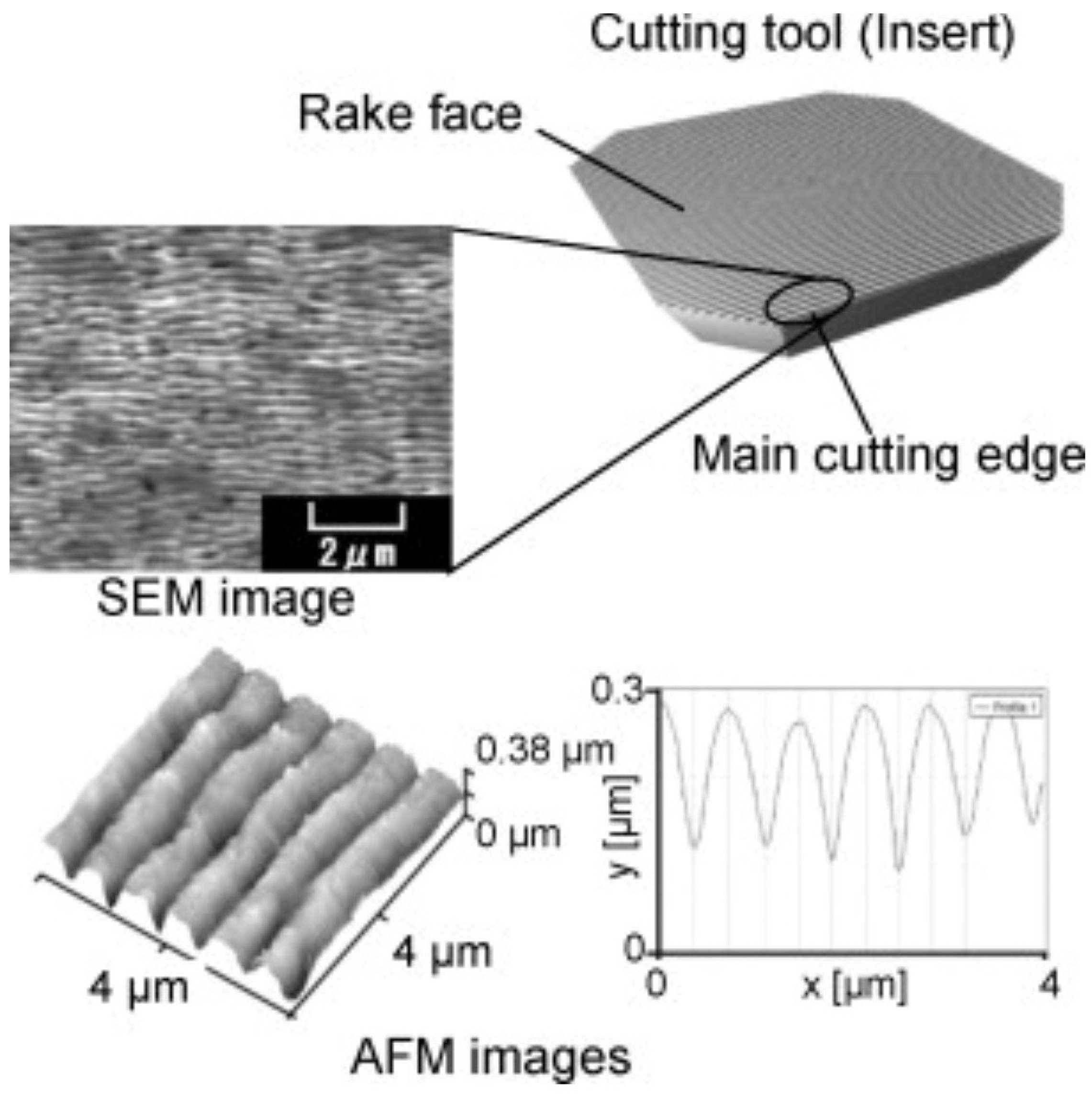
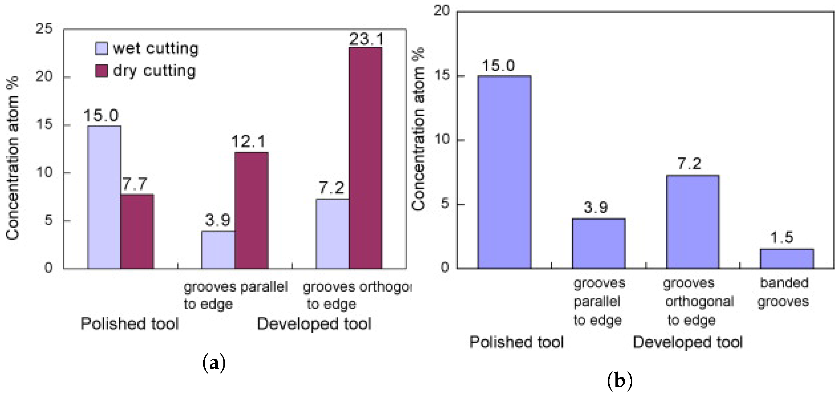
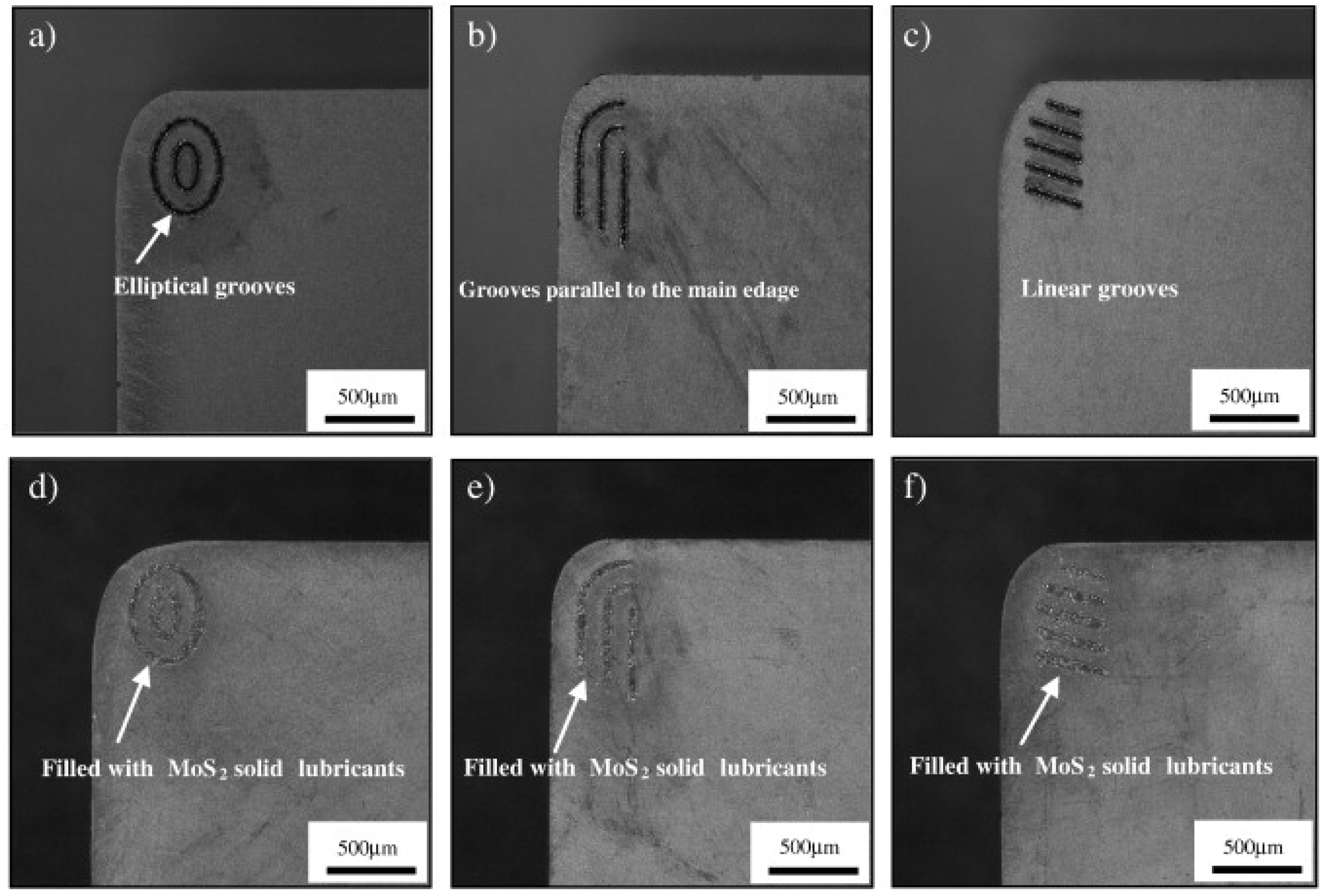
  • For surface-textured cutting tools, the majority of research studies have employed a form of a joint structure named a “groove”. However, the best orientation for a grove is still being researched. These textures may be helpful for dry and wet-cutting machining, whereas the application of discontinuous textures on cutting tools requires more exploration. Pattern- and groove- optimizations are dependent on cutting parameters and workpiece or tool materials. Finally, surface texturing can be utilized effectively in combination with solid lubricants and coatings.
  • Overall, the finite element analysis matches the experimental approach very well.
In conclusion, the operations discussed in this study should result in higher quality machined components, improved machining efficiency, and reduced consumption of raw materials for cutting tools. However, due to the importance of using raw materials, it is crucial for various strategies to be merged in a cohesive manner, along with a new approach to designing materials, cutting tools, and manufacturing processes, to promote the adoption of best practices and habits in the circular economy.

Author Contributions

Conceptualization, A.E. and J.-H.O.; validation, A.E. and S.-J.Z.; investigation, A.E., S.-J.Z., Y.-M.W. and Y.-J.W.; resources, A.E. and S.-J.Z.; data curation, A.E., S.-J.Z., Z.-G.L. and Y.-M.W.; writing—original draft preparation, A.E. and S.-J.Z.; writing—review and editing, A.E., J.-H.O. and Y.-J.W.; visualisation, A.E. and J.-H.O.; supervision, J.-H.O.; funding acquisition, J.-H.O. All authors have read and agreed to the published version of the manuscript.

Funding

This work was financially supported in part by the Natural Science Foundation of China under grant no. U22A20128.

Institutional Review Board Statement

Not applicable.

Data Availability Statement

Data sharing does not apply to this article.

Conflicts of Interest

The authors declare no conflict of interest.

Abbreviations

The following abbreviations are used in this manuscript:
COFcoefficient of friction
DLCdiamond-like carbon
FEAfinite element analysis
ALEarbitrary Lagrangian–Eulerian
FIBfocused ion beam
YSZyttria-stabilized zirconia
Dpdeformation plasticity
DLCdiamond-like carbon
SEMscanning electron microscope
EDXenergy-dispersive X-ray
HSShigh-speed steel
HRARockwell hardness A-class
HPhot pressing
SPSspark plasma sintering
HIPhot isostatic pressing
MSmicrowave sintering
PTFEpolytetrafluoroethylene
PEEKpolyether ether ketone
hBNhexagonal boron nitride
MQLminimum quantity lubrication
MQCLminimum quantity cooling lubrication
MWCNTmulti-walled carbon nanotubes
HSShigh-speed steel
EP/AWextreme pressure and anti-wear additives

References

  1. Davis, J.R.; Allen, P.; Lampman, S.; Zorc, T.B.; Henry, S.D.; Daquila, J.L.; Ronke, A.W. Metals Handbook: Properties and Selection: Nonferrous Alloys and Special-Purpose Materials; ASM International: Almere, The Netherlands, 1990. [Google Scholar]
  2. Mussler, B.H.; Venigalla, S.; Johnson, W.C.; Rudolph, S. Advanced materials and powders. Am. Ceram. Soc. Bull. 2000, 79, 45–56. [Google Scholar]
  3. Lee, H.; Speyer, R.F. Pressureless sintering of boron carbide. J. Am. Ceram. Soc. 2003, 86, 1468–1473. [Google Scholar] [CrossRef]
  4. Kübarsepp, J.; Juhani, K. Cermets with Fe-alloy binder: A review. Int. J. Refract. Met. Hard Mater. 2020, 92, 105290. [Google Scholar] [CrossRef]
  5. Grigoriev, S.N.; Fedorov, S.V.; Hamdy, K. Materials, properties, manufacturing methods and cutting performance of innovative ceramic cutting tools—A review. Manuf. Rev. 2019, 6, 19. [Google Scholar] [CrossRef] [Green Version]
  6. Huo, S.; Wang, Y.; Yao, M.; Zhang, Z.; Chen, L.; Gu, H.; Ouyang, J.; Zhou, Y. Novel TiC-based composites with enhanced mechanical properties. J. Eur. Ceram. Soc. 2021, 41, 5466–5473. [Google Scholar] [CrossRef]
  7. Zou, B.; Ji, W.; Huang, C.; Wang, J.; Li, S.; Xu, K. Effects of superfine refractory carbide additives on microstructure and mechanical properties of TiB2–TiC+ Al2O3 composite ceramic cutting tool materials. J. Alloys Compd. 2014, 585, 192–202. [Google Scholar] [CrossRef]
  8. Zou, B.; Ji, W.; Huang, C.; Xu, K.; Li, S. Degradation of strength properties and its fracture behaviour of TiB2-TiC-based composite ceramic cutting tool materials at the high temperature. Int. J. Refract. Met. Hard Mater. 2014, 47, 1–11. [Google Scholar] [CrossRef]
  9. Sugihara, T.; Singh, P.; Enomoto, T. Development of novel cutting tools with dimple textured surfaces for dry machining of aluminum alloys. Procedia Manuf. 2017, 14, 111–117. [Google Scholar] [CrossRef]
  10. Kalpakjian, S.; Schmid, S. Manufacturing, Engineering and Technology SI 6th Edition-Serope Kalpakjian and Stephen Schmid: Manufacturing, Engineering and Technology; Digital Designs: Charlotte, NC, USA, 2006. [Google Scholar]
  11. Bhuiyan, M.; Choudhury, I.; Dahari, M. Monitoring the tool wear, surface roughness and chip formation occurrences using multiple sensors in turning. J. Manuf. Syst. 2014, 33, 476–487. [Google Scholar] [CrossRef]
  12. Sharma, V.S.; Dogra, M.; Suri, N. Cooling techniques for improved productivity in turning. Int. J. Mach. Tools Manuf. 2009, 49, 435–453. [Google Scholar] [CrossRef]
  13. Boothroyd, G. Fundamentals of Metal Machining and Machine Tools; CRC Press: Boca Raton, FL, USA, 1988; Volume 28. [Google Scholar]
  14. Liew, P.J.; Shaaroni, A.; Sidik, N.A.C.; Yan, J. An overview of current status of cutting fluids and cooling techniques of turning hard steel. Int. J. Heat Mass Transf. 2017, 114, 380–394. [Google Scholar] [CrossRef]
  15. Chan, C.; Lee, W.B.; Wang, H. Enhancement of surface finish using water-miscible nano-cutting fluid in ultra-precision turning. Int. J. Mach. Tools Manuf. 2013, 73, 62–70. [Google Scholar] [CrossRef]
  16. Sreejith, P. Machining of 6061 aluminium alloy with MQL, dry and flooded lubricant conditions. Mater. Lett. 2008, 62, 276–278. [Google Scholar] [CrossRef]
  17. Anton, S.; Andreas, S.; Friedrich, B. Heat dissipation in turning operations by means of internal cooling. Procedia Eng. 2015, 100, 1116–1123. [Google Scholar] [CrossRef] [Green Version]
  18. Hao, G.; Liu, Z.; Liang, X.; Zhao, J. Influences of TiAlN coating on cutting temperature during orthogonal machining H13 hardened steel. Coatings 2019, 9, 355. [Google Scholar] [CrossRef] [Green Version]
  19. John, M.; Menezes, P.L. Self-lubricating materials for extreme condition applications. Materials 2021, 14, 5588. [Google Scholar] [CrossRef]
  20. Kumar, R.; Antonov, M. Self-lubricating materials for extreme temperature tribo-applications. Mater. Today Proc. 2021, 44, 4583–4589. [Google Scholar] [CrossRef]
  21. Torres, H.; Rodríguez Ripoll, M.; Prakash, B. Tribological behaviour of self-lubricating materials at high temperatures. Int. Mater. Rev. 2018, 63, 309–340. [Google Scholar] [CrossRef]
  22. Ozcelik, B.; Kuram, E.; Cetin, M.H.; Demirbas, E. Experimental investigations of vegetable based cutting fluids with extreme pressure during turning of AISI 304L. Tribol. Int. 2011, 44, 1864–1871. [Google Scholar] [CrossRef]
  23. Haider, J.; Hashmi, M. 8.02—Health and environmental impacts in metal machining processes. Compr. Mater. Process. 2014, 8, 7–33. [Google Scholar]
  24. Vamsi Krishna, P.; Srikant, R.; Nageswara Rao, D. Solid lubricants in machining. Proc. Inst. Mech. Eng. Part J J. Eng. Tribol. 2011, 225, 213–227. [Google Scholar] [CrossRef]
  25. Lathkar, G.; Bas, U. Clean metal cutting process using solid lubricants. In Proceedings of the 19th AIMTDR Conference, Narosa, Madras, India, 14–16 December 2000; pp. 15–31. [Google Scholar]
  26. Rizzo, A.; Goel, S.; Luisa Grilli, M.; Iglesias, R.; Jaworska, L.; Lapkovskis, V.; Novak, P.; Postolnyi, B.O.; Valerini, D. The critical raw materials in cutting tools for machining applications: A review. Materials 2020, 13, 1377. [Google Scholar] [CrossRef] [Green Version]
  27. Sarkar, M.; Sadhu, K.K.; Chakraborty, S.S.; Mandal, N. Simultaneous effect of CaF2 and TiC on tribological properties of ZTA ceramics for high temperature application. Mater. Today Proc. 2022, 57, 116–120. [Google Scholar] [CrossRef]
  28. Vazirisereshk, M.R.; Martini, A.; Strubbe, D.A.; Baykara, M.Z. Solid lubrication with MoS2: A review. Lubricants 2019, 7, 57. [Google Scholar] [CrossRef] [Green Version]
  29. Akhtar, S.S. A critical review on self-lubricating ceramic-composite cutting tools. Ceram. Int. 2021, 47, 20745–20767. [Google Scholar] [CrossRef]
  30. Li, L.; Li, Y. Development and trend of ceramic cutting tools from the perspective of mechanical processing. In IOP Conference Series: Earth and Environmental Science; IOP Publishing: Bristol, UK, 2017; Volume 94, p. 012062. [Google Scholar]
  31. Huo, S.; Wang, Y.; Chen, Q.; Yao, M.; Chen, L.; Gu, H.; Liu, L.; Ouyang, J.; Zhou, Y. Reactive hot pressing of super hard (Ti, Ta)(B, C)–(Ta, Ti) C composites. Mater. Sci. Eng. A 2021, 800, 140292. [Google Scholar] [CrossRef]
  32. Huo, S.; Wang, Y.; Kong, Q.; Chen, L.; Yao, M.; Gu, H.; Ouyang, J.; Fu, Y.; Zhou, Y. In situ reaction and solid solution induced hardening in (Ti, Zr) B2-(Zr, Ti) C composites. J. Am. Ceram. Soc. 2020, 103, 6101–6105. [Google Scholar] [CrossRef]
  33. Kong, Q.; Huo, S.; Chen, L.; Wang, Y.; Ouyang, J.; Zhou, Y. Novel (Zr, Ti) B2-(Zr, Ti) C-SiC ceramics via reactive hot pressing. J. Eur. Ceram. Soc. 2022, 42, 4045–4052. [Google Scholar] [CrossRef]
  34. Zhu, Z.; Yin, Z.; Hong, D.; Yuan, J. Preparation of complex-shaped Al2O3/SiCp/SiCw ceramic tool by two-step microwave sintering. Ceram. Int. 2020, 46, 27362–27372. [Google Scholar] [CrossRef]
  35. Wang, X.; Zhao, J.; Cui, E.; Sun, Z.; Yu, H. Nano/microstructures and mechanical properties of Al2O3-WC-TiC ceramic composites incorporating graphene with different sizes. Mater. Sci. Eng. A 2021, 812, 141132. [Google Scholar] [CrossRef]
  36. Cui, E.; Zhao, J.; Wang, X.; Sun, J.; Huang, X.; Wang, C. Microstructure and toughening mechanisms of Al2O3/(W, Ti) C/graphene composite ceramic tool material. Ceram. Int. 2018, 44, 13538–13543. [Google Scholar] [CrossRef]
  37. Bai, X.; Huang, C.; Wang, J.; Zou, B.; Liu, H. Fabrication and characterization of Si3N4 reinforced Al2O3-based ceramic tool materials. Ceram. Int. 2015, 41, 12798–12804. [Google Scholar] [CrossRef]
  38. Zhang, Z.; Liu, Y.; Liu, H. Mechanical properties and microstructure of spark plasma sintered Al2O3-SiCw-Si3N4 composite ceramic tool materials. Ceram. Int. 2022, 48, 5527–5534. [Google Scholar] [CrossRef]
  39. Tan, D.W.; Zhu, L.L.; Wei, W.X.; Yu, J.J.; Zhou, Y.Z.; Guo, W.M.; Lin, H.T. Performance improvement of Si3N4 ceramic cutting tools by tailoring of phase composition and microstructure. Ceram. Int. 2020, 46, 26182–26189. [Google Scholar] [CrossRef]
  40. Xu, W.; Yin, Z.; Yuan, J.; Wang, Z.; Liu, Y. Preparation and characterization of Si3N4-based composite ceramic tool materials by microwave sintering. Ceram. Int. 2017, 43, 16248–16257. [Google Scholar] [CrossRef]
  41. Sun, N.; Wang, Z.; Yu, B.; Huang, L.; Yin, Z.; Yuan, J. Effects of Ti (C, N) addition on the microstructure and mechanical properties of spark plasma sintered Si3N4/Ti (C, N) ceramic tool material. Ceram. Int. 2020, 46, 28459–28466. [Google Scholar] [CrossRef]
  42. Guo, F.; Yin, Z.; Chen, W.; Liu, H.; Hong, D.; Yuan, J. Spark plasma sintering of multi-cation doped (Yb, Sm) α/β-SiAlON ceramic tool materials: Effects of cation type, composition, and sintering temperature. Ceram. Int. 2022, 48, 32730–32739. [Google Scholar] [CrossRef]
  43. Zhao, J. The use of ceramic matrix composites for metal cutting applications. In Advances in Ceramic Matrix Composites; Elsevier: Amsterdam, The Netherlands, 2014; pp. 623–654. [Google Scholar]
  44. Seleznev, A.; Pinargote, N.W.S.; Smirnov, A. Ceramic Cutting Materials and Tools Suitable for Machining High-Temperature Nickel-Based Alloys: A Review. Metals 2021, 11, 1385. [Google Scholar] [CrossRef]
  45. Fang, Z.Z.; Koopman, M.C.; Wang, H. 1.04—Cemented Tungsten Carbide Hardmetal-An Introduction; Elsevier: Oxford, UK, 2014; pp. 123–137. [Google Scholar]
  46. Mari, D.; Miguel, L.; Nebel, C. Comprehensive Hard Materials; Elsevier: Amsterdam, The Netherlands, 2014. [Google Scholar]
  47. Song, J.; Huang, C.; Lv, M.; Zou, B.; Wang, S.; Wang, J.; An, J. Effects of TiC content and melt phase on microstructure and mechanical properties of ternary TiB2-based ceramic cutting tool materials. Mater. Sci. Eng. A 2014, 605, 137–143. [Google Scholar] [CrossRef]
  48. Rodriguez, N.; Sanchez, J.; Aristizabal, M. Consolidation of (Ti, Mo)(C, N)–Ni cermets by glass encapsulated hot isostatic pressing. Mater. Sci. Eng. A 2011, 528, 4453–4461. [Google Scholar]
  49. Xu, W.; Yin, Z.; Yuan, J.; Yan, G. Reliability prediction of a microwave sintered Si3N4-based composite ceramic tool. Ceram. Int. 2021, 47, 16737–16745. [Google Scholar] [CrossRef]
  50. Zhang, W.; Chen, L.; Xu, C.; Lu, W.; Wang, Y.; Ouyang, J.; Zhou, Y. Densification, microstructure and mechanical properties of multicomponent (TiZrHfNbTaMo) C ceramic prepared by pressureless sintering. J. Mater. Sci. Technol. 2021, 72, 23–28. [Google Scholar] [CrossRef]
  51. Bordia, R.K.; Kang, S.J.L.; Olevsky, E.A. Current understanding and future research directions at the onset of the next century of sintering science and technology. J. Am. Ceram. Soc. 2017, 100, 2314–2352. [Google Scholar] [CrossRef] [Green Version]
  52. Hu, H.; Liu, X.; Chen, J.; Lu, H.; Liu, C.; Wang, H.; Luan, J.; Jiao, Z.; Liu, Y.; Song, X. High-temperature mechanical behavior of ultra-coarse cemented carbide with grain strengthening. J. Mater. Sci. Technol. 2022, 104, 8–18. [Google Scholar] [CrossRef]
  53. Zhao, C.; Lu, H.; Liu, X.; Liu, C.; Nie, Z.; Song, X. Strengthening cemented carbides by activated nano TaC. Int. J. Refract. Met. Hard Mater. 2021, 95, 105449. [Google Scholar] [CrossRef]
  54. Xie, D.; Gan, X.; Xiong, H.; Li, Z.; Zhou, K. Nano TiC modified Ti (C, N)-based cermets with weakened rim-binder interfaces. Mater. Sci. Eng. 2022, 845, 143194. [Google Scholar] [CrossRef]
  55. Dong, D.; Yang, W.; Xiang, X.; Huang, B.; Xiong, H.; Zhang, L.; Shi, K. Microstructural evolution and phase transition mechanism of Ti (C, N)-based cermets during vacuum sintering process. Ceram. Int. 2021, 47, 8020–8029. [Google Scholar] [CrossRef]
  56. Wang, B.; Wang, J.; Chang, A.; Yao, J. Bismuth trioxide-tailored sintering temperature, microstructure and NTCR characteristics of Mn1.1Co1.5Fe0.4O4 ceramics. RSC Adv. 2019, 9, 25488–25495. [Google Scholar] [CrossRef] [Green Version]
  57. Zhao, B.; Liu, H.; Wang, J.; Huang, C.; Zhu, H.; Liu, X. Influence of novel sintering process on the densification and microstructures of ceramic composite materials. Ceram. Int. 2020, 46, 6733–6737. [Google Scholar] [CrossRef]
  58. Cheng, M.; Liu, H.; Zhao, B.; Huang, C.; Yao, P.; Wang, B. Mechanical properties of two types of Al2O3/TiC ceramic cutting tool material at room and elevated temperatures. Ceram. Int. 2017, 43, 13869–13874. [Google Scholar] [CrossRef]
  59. Wang, L.; Liu, H.; Huang, C.; Liu, X.; Zou, B.; Zhao, B. Microstructure and mechanical properties of TiC–TiB2 composite cermet tool materials at ambient and elevated temperature. Ceram. Int. 2016, 42, 2717–2723. [Google Scholar] [CrossRef]
  60. Wang, X.; Zhao, J.; Cui, E.; Sun, Z.; Yu, H. Grain growth kinetics and grain refinement mechanism in Al2O3/WC/TiC/graphene ceramic composite. J. Eur. Ceram. Soc. 2021, 41, 1391–1398. [Google Scholar] [CrossRef]
  61. Wang, X.; Zhao, J.; Cui, E.; Song, S.; Liu, H.; Song, W. Microstructure, mechanical properties and toughening mechanisms of graphene reinforced Al2O3-WC-TiC composite ceramic tool material. Ceram. Int. 2019, 45, 10321–10329. [Google Scholar] [CrossRef]
  62. Cui, E.; Zhao, J.; Wang, X. Determination of microstructure and mechanical properties of graphene reinforced Al2O3-Ti (C, N) ceramic composites. Ceram. Int. 2019, 45, 20593–20599. [Google Scholar] [CrossRef]
  63. Cui, E.; Zhao, J.; Wang, X. Effects of nano-ZrO2 content on microstructure and mechanical properties of GNPs/nano-ZrO2 reinforced Al2O3/Ti (C, N) composite ceramics. J. Eur. Ceram. Soc. 2020, 40, 1532–1538. [Google Scholar] [CrossRef]
  64. Wang, X.; Zhao, J.; Cui, E.; Liu, H.; Dong, Y.; Sun, Z. Effects of sintering parameters on microstructure, graphene structure stability and mechanical properties of graphene reinforced Al2O3-based composite ceramic tool material. Ceram. Int. 2019, 45, 23384–23392. [Google Scholar] [CrossRef]
  65. Cui, E.; Zhao, J.; Wang, X.; Song, S. Cutting performance, failure mechanisms and tribological properties of GNPs reinforced Al2O3/Ti (C, N) ceramic tool in high speed turning of Inconel 718. Ceram. Int. 2020, 46, 18859–18867. [Google Scholar] [CrossRef]
  66. Zhao, B.; Liu, H.; Huang, C.; Wang, J.; Cheng, M. Fabrication and mechanical properties of Al2O3-SiCw-TiCnp ceramic tool material. Ceram. Int. 2017, 43, 10224–10230. [Google Scholar] [CrossRef]
  67. Zhao, B.; Liu, H.; Huang, C.; Wang, J.; Cheng, M.; Zhan, Q. Evolution mechanisms of high temperature mechanical properties and microstructures of Al2O3/SiCw/TiCn nanocomposite materials. J. Alloys Compd. 2018, 737, 46–52. [Google Scholar] [CrossRef]
  68. Bai, X.; Huang, C.; Wang, J.; Zou, B.; Liu, H. Sintering mechanisms of Al2O3-based composite ceramic tools having 25% Si3N4 additions. Int. J. Refract. Met. Hard Mater. 2018, 73, 132–138. [Google Scholar] [CrossRef]
  69. Zheng, G.; Zhao, J.; Zhou, Y.; Gao, Z.; Cui, X.; Li, A. Fabrication and characterization of Sialon–Si3N4 graded nano-composite ceramic tool materials. Compos. Part B Eng. 2011, 42, 1813–1820. [Google Scholar] [CrossRef]
  70. Zheng, G.; Zhao, J.; Gao, Z.; Cao, Q. Cutting performance and wear mechanisms of Sialon–Si3N4 graded nano-composite ceramic cutting tools. Int. J. Adv. Manuf. Technol. 2012, 58, 19–28. [Google Scholar] [CrossRef]
  71. Tian, X.; Zhao, J.; Wang, Y.; Gong, F.; Qin, W.; Pan, H. Fabrication and mechanical properties of Si3N4/(W, Ti) C/Co graded nano-composite ceramic tool materials. Ceram. Int. 2015, 41, 3381–3389. [Google Scholar] [CrossRef]
  72. Wu, G.; Xu, C.; Xiao, G.; Yi, M.; Chen, Z.; Xu, L. Self-lubricating ceramic cutting tool material with the addition of nickel coated CaF2 solid lubricant powders. Int. J. Refract. Met. Hard Mater. 2016, 56, 51–58. [Google Scholar] [CrossRef]
  73. Wang, J.; Yi, M.; Xu, C.; Xiao, G.; Chen, Z.; Zhang, J.; Wang, L. Mechanical property and cutting performance of (W, Ti) C based ceramic composites with the addition of nano-sized CaF2. Int. J. Refract. Met. Hard Mater. 2021, 99, 105607. [Google Scholar] [CrossRef]
  74. Wu, G.; Xu, C.; Xiao, G.; Yi, M.; Chen, Z. Structure design of Al2O3/TiC/CaF2 multicomponent gradient self-lubricating ceramic composite and its tribological behaviors. Ceram. Int. 2018, 44, 5550–5563. [Google Scholar] [CrossRef]
  75. Wu, G.; Xu, C.; Xiao, G.; Yi, M.; Chen, Z.; Chen, H. An advanced self-lubricating ceramic composite with the addition of core-shell structured h-BN@ Ni powders. Int. J. Refract. Met. Hard Mater. 2018, 72, 276–285. [Google Scholar] [CrossRef]
  76. Lonergan, J.M.; Fahrenholtz, W.G.; Hilmas, G.E. Sintering mechanisms and kinetics for reaction hot-pressed ZrB2. J. Am. Ceram. Soc. 2015, 98, 2344–2351. [Google Scholar] [CrossRef]
  77. Cheng, L.; Xie, Z.; Liu, G. Spark plasma sintering of TiC ceramic with tungsten carbide as a sintering additive. J. Eur. Ceram. Soc. 2013, 33, 2971–2977. [Google Scholar] [CrossRef]
  78. Cheng, L.; Xie, Z.; Liu, G.; Liu, W.; Xue, W. Densification and mechanical properties of TiC by SPS-effects of holding time, sintering temperature and pressure condition. J. Eur. Ceram. Soc. 2012, 32, 3399–3406. [Google Scholar] [CrossRef]
  79. Zhang, J.; Xiao, G.; Yi, M.; Chen, Z.; Zhang, J.; Chen, H.; Shang, X.; Xu, C. Mechanical properties of ZrB2/SiC/WC ceramic tool materials from room temperature to 1100° C and cutting performance. Int. J. Refract. Met. Hard Mater. 2021, 101, 105697. [Google Scholar] [CrossRef]
  80. Chen, B.; Xiao, G.; Yi, M.; Zhang, J.; Zhou, T.; Chen, Z.; Xu, C. Mechanical properties and microstructure of Al2O3/TiB2 and Al2O3/TiB2/gnps ceramic tool materials prepared by spark plasma sintering. Ceram. Int. 2021, 47, 11748–11755. [Google Scholar] [CrossRef]
  81. De Oro Calderon, R.; Gierl-Mayer, C.; Danninger, H. Fundamentals of sintering: Liquid phase sintering. In Encyclopedia of Materials: Metals and Alloys; Elsevier: Oxford, UK, 2022; pp. 481–492. [Google Scholar]
  82. German, R.M.; Suri, P.; Park, S.J. Liquid phase sintering. J. Mater. Sci. 2009, 44, 1–39. [Google Scholar] [CrossRef] [Green Version]
  83. Zhou, H.; Huang, C.; Zou, B.; Liu, H.; Zhu, H.; Yao, P.; Wang, J. Effects of sintering processes on the mechanical properties and microstructure of Ti (C, N)-based cermet cutting tool materials. Int. J. Refract. Met. Hard Mater. 2014, 47, 71–79. [Google Scholar] [CrossRef]
  84. Zhuang, Q.; Lin, N.; He, Y.; Kang, X. Influence of temperature on sintering behavior and properties of TiC-Fe-Co-Ni-Cr-Mo cermets. Ceram. Int. 2017, 43, 15992–15998. [Google Scholar] [CrossRef]
  85. Wang, X.; Wang, Q.; Dong, Z.; Zhou, X.; Wang, X.; Zhang, B.; Meng, C. Microstructure and Mechanical Properties of Multicomponent Metal Ti (C, N)-Based Cermets. Metals 2020, 10, 927. [Google Scholar] [CrossRef]
  86. Labonne, M.; Missiaen, J.M.; Lay, S. Cooperative grain boundary and phase boundary migration for the grain growth in NbC-based cemented carbides. Acta Mater. 2021, 221, 117363. [Google Scholar] [CrossRef]
  87. Findenig, G.; Buchegger, C.; Lengauer, W.; Veitsch, C.; Demoly, A. Investigation of the main influencing parameters on the degassing behavior of titanium carbonitrides using mass spectrometry. Int. J. Refract. Met. Hard Mater. 2017, 63, 38–46. [Google Scholar] [CrossRef]
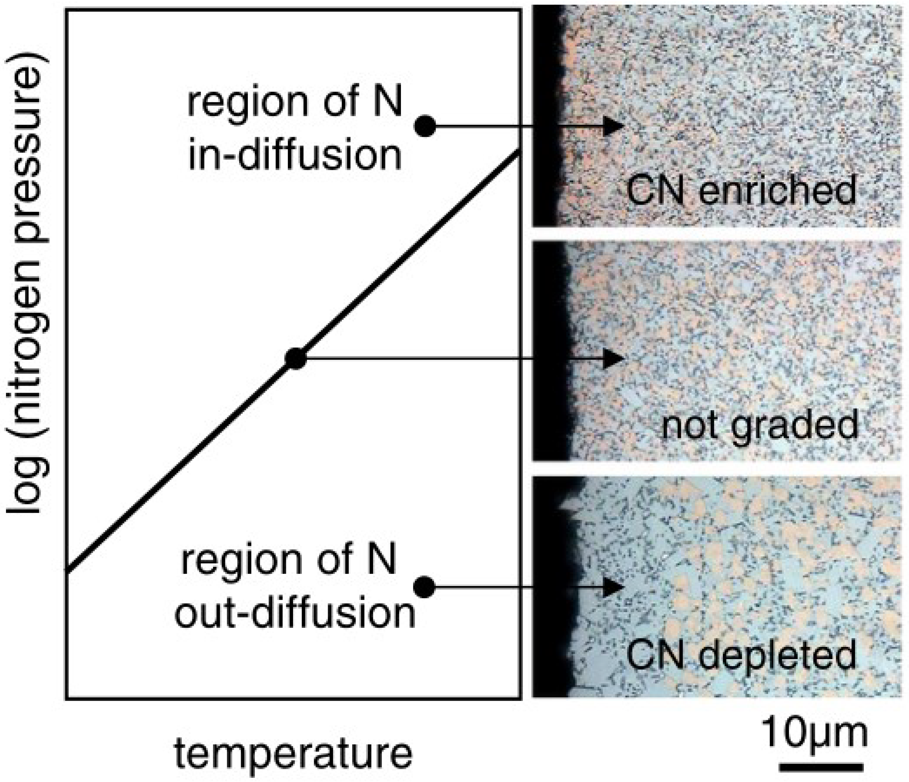
  88. Wang, Q.; Li, N.; Zhang, W.; Yu, Z.; Liu, Y.; Li, Y. Effect of the nitrogen multi-sources on the microstructure and hardness of the graded surface layer in WC–Co–Cubic cemented carbides. Ceram. Int. 2022, 48, 15855–15861. [Google Scholar] [CrossRef]
  89. Chu, S.; Liu, G.; Xiong, H.; Li, Z.; Zhou, K. High-quality Ti (C, N)-based cermets via solid-state nitrogen-pressure sintering: Influence of the sintering atmosphere. Int. J. Refract. Met. Hard Mater. 2020, 92, 105291. [Google Scholar] [CrossRef]
  90. Zhou, P.; Du, Y.; Lengauer, W. Morphology of η phase in cemented carbides with Fe-based binders influenced by carbon content and nitrogen atmosphere. Ceram. Int. 2019, 45, 20774–20779. [Google Scholar] [CrossRef]
  91. Glühmann, J.; Schneeweiß, M.; Van den Berg, H.; Kassel, D.; Rödiger, K.; Dreyer, K.; Lengauer, W. Functionally graded WC–Ti (C, N)–(Ta, Nb) C–Co hardmetals: Metallurgy and performance. Int. J. Refract. Met. Hard Mater. 2013, 36, 38–45. [Google Scholar] [CrossRef]
  92. Janisch, D.; Lengauer, W.; Rödiger, K.; Dreyer, K.; Van den Berg, H. Novel fine-grained hardmetals by use of multiphase powder precursors and reactive nitrogen sintering. Int. J. Refract. Met. Hard Mater. 2010, 28, 362–369. [Google Scholar] [CrossRef]
  93. Wang, Q.; He, X.; Li, N.; Zhang, W.; Du, Y. Preparation of a novel dual structure graded cemented carbides induced by bidirectional diffusion. Mater. Lett. 2022, 312, 131689. [Google Scholar] [CrossRef]
  94. Li, N.; Li, X.; Zhang, W.; Du, Y. Relation between the nitrogen gas pressure and structure characteristics of WC–Ti (C, N)–Co graded cemented carbides. J. Alloys Compd. 2020, 831, 154764. [Google Scholar] [CrossRef]
  95. Zhao, Y.; Zheng, Y.; Zhou, W.; Zhang, J.; Zhang, G.; Xiong, W. Microstructure and performance of functionally gradient Ti (C, N)-based cermets fabricated by low-pressure carburizing treatment during liquid phase sintering. Ceram. Int. 2017, 43, 1956–1962. [Google Scholar] [CrossRef]
  96. Zhao, Y.; Zheng, Y.; Li, Y.; Zhou, W.; Zhang, G.; Zhang, J.; Xiong, W. Microstructure and performance of graded Ti (C, N)-based cermets modified by nitriding treatment during different sintering stages. Int. J. Refract. Met. Hard Mater. 2017, 62, 1–8. [Google Scholar] [CrossRef]
  97. Shah, R.; Chen, R.; Woydt, M.; Baumann, C.; Jurs, J.; Iaccarino, P. High temperature tribology under linear oscillation motion. Lubricants 2020, 9, 5. [Google Scholar] [CrossRef]
  98. Kumar, R.; Antonov, M.; Liu, L.; Hussainova, I. Sliding wear performance of in-situ spark plasma sintered Ti-TiBw composite at temperatures up to 900 C. Wear 2021, 476, 203663. [Google Scholar] [CrossRef]
  99. Ouyang, J.H.; Liang, X.S. High-temperature solid lubricating materials. Encycl. Tribol. 2013, 11, 1671–1681. [Google Scholar]
  100. Donnet, C.; Erdemir, A. Solid lubricant coatings: Recent developments and future trends. Tribol. Lett. 2004, 17, 389–397. [Google Scholar] [CrossRef]
  101. Wang, Q.; Zheng, F.; Wang, T. Tribological properties of polymers PI, PTFE and PEEK at cryogenic temperature in vacuum. Cryogenics 2016, 75, 19–25. [Google Scholar] [CrossRef]
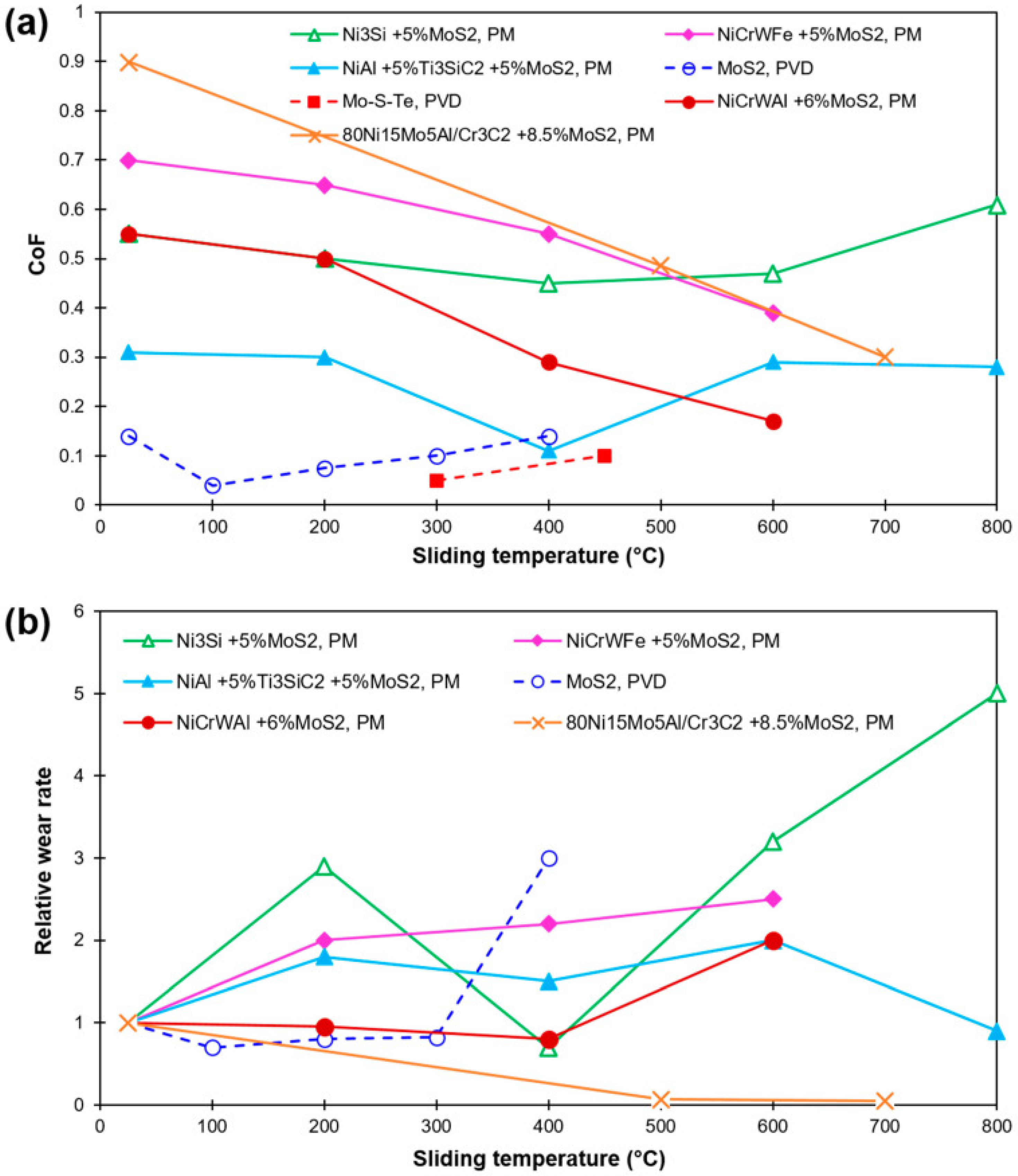
  102. Shi, X.; Song, S.; Zhai, W.; Wang, M.; Xu, Z.; Yao, J.; ud Din, A.Q.; Zhang, Q. Tribological behavior of Ni3Al matrix self-lubricating composites containing WS2, Ag and hBN tested from room temperature to 800 °C. Mater. Des. 2014, 55, 75–84. [Google Scholar] [CrossRef]
  103. Yang, J.F.; Jiang, Y.; Hardell, J.; Prakash, B.; Fang, Q.F. Influence of service temperature on tribological characteristics of self-lubricant coatings: A review. Front. Mater. Sci. 2013, 7, 28–39. [Google Scholar] [CrossRef]
  104. Sartori, S.; Ghiotti, A.; Bruschi, S. Solid lubricant-assisted minimum quantity lubrication and cooling strategies to improve Ti6Al4V machinability in finishing turning. Tribol. Int. 2018, 118, 287–294. [Google Scholar] [CrossRef]
  105. Essa, F.; Zhang, Q.; Huang, X. Investigation of the effects of mixtures of WS2 and ZnO solid lubricants on the sliding friction and wear of M50 steel against silicon nitride at elevated temperatures. Wear 2017, 374, 128–141. [Google Scholar] [CrossRef]
  106. Ouyang, J.H.; Li, Y.F.; Zhang, Y.Z.; Wang, Y.M.; Wang, Y.J. High-temperature solid lubricants and self-lubricating composites: A critical review. Lubricants 2022, 10, 177. [Google Scholar] [CrossRef]
  107. Polcar, T.; Cavaleiro, A. Review on self-lubricant transition metal dichalcogenide nanocomposite coatings alloyed with carbon. Surf. Coat. Technol. 2011, 206, 686–695. [Google Scholar] [CrossRef]
  108. Scharf, T.; Prasad, S. Solid lubricants: A review. J. Mater. Sci. 2013, 48, 511–531. [Google Scholar] [CrossRef]
  109. Ouyang, J.H.; Liang, X.S. High-Temperature Solid Lubricating Materials. In Encyclopedia of Tribology; Springer US: Boston, MA, USA, 2013; pp. 1671–1681. [Google Scholar]
  110. Yang, R.; Liu, Z.; Wang, Y.; Yang, G.; Li, H. Synthesis and characterization of MoS2/Ti composite coatings on Ti6Al4V prepared by laser cladding. AIP Adv. 2013, 3, 022106. [Google Scholar] [CrossRef] [Green Version]
  111. Muratore, C.; Voevodin, A.A. Molybdenum disulfide as a lubricant and catalyst in adaptive nanocomposite coatings. Surf. Coatings Technol. 2006, 201, 4125–4130. [Google Scholar] [CrossRef]
  112. Kong, L.; Bi, Q.; Niu, M.; Zhu, S.; Yang, J.; Liu, W. High-temperature tribological behavior of ZrO2–MoS2–CaF2 self-lubricating composites. J. Eur. Ceram. Soc. 2013, 33, 51–59. [Google Scholar] [CrossRef]
  113. Kumar, R.; Hussainova, I.; Rahmani, R.; Antonov, M. Solid Lubrication at High-Temperatures—A Review. Materials 2022, 15, 1695. [Google Scholar] [CrossRef]
  114. Zhou, Y.; Dong, Y.; Yin, H.; Li, Z.; Yan, R.; Li, D.; Gu, Z.; Sun, X.; Shi, L.; Zhang, Z. Characterizing thermal-oxidation behaviors of nuclear graphite by combining O2 supply and micro surface area of graphite. Sci. Rep. 2018, 8, 13400. [Google Scholar] [CrossRef] [Green Version]
  115. Li, C.; Chen, X.; Shen, L.; Bao, N. Revisiting the oxidation of graphite: Reaction mechanism, chemical stability, and structure self-regulation. ACS Omega 2020, 5, 3397–3404. [Google Scholar] [CrossRef]
  116. Liu, J.; Shi, Y. Microstructure and wear behavior of laser-cladded Ni-based coatings decorated by graphite particles. Surf. Coatings Technol. 2021, 412, 127044. [Google Scholar] [CrossRef]
  117. Kim, T.; Singh, D.; Singh, M. Enhancement of oxidation resistance of graphite foams by polymer derived-silicon carbide coating for concentrated solar power applications. Energy Procedia 2015, 69, 900–906. [Google Scholar] [CrossRef] [Green Version]
  118. Berman, D.; Erdemir, A.; Sumant, A.V. Graphene: A new emerging lubricant. Mater. Today 2014, 17, 31–42. [Google Scholar] [CrossRef]
  119. Xu, Z.; Zhang, Q.; Jing, P.; Zhai, W. High-temperature tribological performance of TiAl matrix composites reinforced by multilayer graphene. Tribol. Lett. 2015, 58, 3. [Google Scholar] [CrossRef]
  120. Li, X.; Gao, Y.; Wei, S.; Yang, Q. Tribological behaviors of B4C-hBN ceramic composites used as pins or discs coupled with B4C ceramic under dry sliding condition. Ceram. Int. 2017, 43, 1578–1583. [Google Scholar] [CrossRef]
  121. Lee, H.H.; Kim, S.H.; Joshi, B.; Lee, S.W. A Study on Mechanical and Tribological Properties of Hot pressed Al2O3/ZrO2/h-BN/TiO2 Composites. In Materials Science Forum; Trans Tech Publications Ltd.: Zurich, Switzerland, 2011; Volume 695, pp. 417–420. [Google Scholar]
  122. Podgornik, B.; Kosec, T.; Kocijan, A.; Donik, Č. Tribological behaviour and lubrication performance of hexagonal boron nitride (h-BN) as a replacement for graphite in aluminium forming. Tribol. Int. 2015, 81, 267–275. [Google Scholar] [CrossRef]
  123. Yan, H.; Wang, A.; Zhang, X.; Huang, Z.; Wang, W.; Xie, J. Nd: YAG laser cladding Ni base alloy/nano-h-BN self-lubricating composite coatings. Mater. Sci. Technol. 2010, 26, 461–468. [Google Scholar] [CrossRef]
  124. Zhang, S.; Zhou, J.; Guo, B.; Zhou, H.; Pu, Y.; Chen, J. Friction and wear behavior of laser cladding Ni/hBN self-lubricating composite coating. Mater. Sci. Eng. A 2008, 491, 47–54. [Google Scholar] [CrossRef]
  125. Tyagi, R.; Xiong, D.S.; Li, J.; Dai, J. Elevated temperature tribological behavior of Ni based composites containing nano-silver and hBN. Wear 2010, 269, 884–890. [Google Scholar] [CrossRef]
  126. Guo, J.; Yan, H.; Zhang, P.; Yu, Z.; Lu, Q.; Chen, Z. Laser cladding NiCrBSi/TiN/h-BN self-lubricating wear resistant coating on Ti–6Al–4V surface. Mater. Res. Express 2019, 6, 066537. [Google Scholar] [CrossRef]
  127. Torres, H.; Slawik, S.; Gachot, C.; Prakash, B.; Ripoll, M.R. Microstructural design of self-lubricating laser claddings for use in high temperature sliding applications. Surf. Coat. Technol. 2018, 337, 24–34. [Google Scholar] [CrossRef]
  128. Kong, L.; Bi, Q.; Zhu, S.; Qiao, Z.; Yang, J.; Liu, W. Effect of CuO on self-lubricating properties of ZrO2 (Y2O3)–Mo composites at high temperatures. J. Eur. Ceram. Soc. 2014, 34, 1289–1296. [Google Scholar] [CrossRef]
  129. Liu, E.; Gao, Y.; Jia, J.; Bai, Y. Friction and wear behaviors of Ni-based composites containing graphite/Ag2MoO4 lubricants. Tribol. Lett. 2013, 50, 313–322. [Google Scholar] [CrossRef]
  130. Zhen, J.; Cheng, J.; Zhu, S.; Hao, J.; Qiao, Z.; Yang, J.; Liu, W. High-temperature tribological behavior of a nickel alloy matrix solid-lubricating composite under vacuum. Tribol. Int. 2017, 110, 52–56. [Google Scholar] [CrossRef]
  131. Zhang, C.; Yang, B.; Wang, J.; Wang, H.; Liu, G.; Zhang, B.; Liu, L.; Feng, K.; Li, Z. Microstructure and friction behavior of LaF3 doped Ti-MoS2 composite thin films deposited by unbalanced magnetron sputtering. Surf. Coat. Technol. 2019, 359, 334–341. [Google Scholar] [CrossRef]
  132. Ouyang, J.; Li, Y.; Wang, Y.; Zhou, Y.; Murakami, T.; Sasaki, S. Microstructure and tribological properties of ZrO2 (Y2O3) matrix composites doped with different solid lubricants from room temperature to 800 °C. Wear 2009, 267, 1353–1360. [Google Scholar] [CrossRef]
  133. Voevodin, A.A.; Muratore, C.; Aouadi, S.M. Hard coatings with high temperature adaptive lubrication and contact thermal management. Surf. Coat. Technol. 2014, 257, 247–265. [Google Scholar] [CrossRef]
  134. Rosenkranz, A.; Costa, H.L.; Baykara, M.Z.; Martini, A. Synergetic effects of surface texturing and solid lubricants to tailor friction and wear—A review. Tribol. Int. 2021, 155, 106792. [Google Scholar] [CrossRef]
  135. Zhu, S.; Cheng, J.; Qiao, Z.; Yang, J. High temperature solid-lubricating materials: A review. Tribol. Int. 2019, 133, 206–223. [Google Scholar] [CrossRef]
  136. Bowden, F.P.; Bowden, F.P.; Tabor, D. The Friction and Lubrication of Solids; University Press: Oxford, UK, 2001; Volume 1. [Google Scholar]
  137. Erdemir, A. Solid lubricants and self-lubricating films. In Modern Tribology Handbook; CRC Press: Boca Raton, FL, USA, 2001; Volume 2, pp. 787–818. [Google Scholar]
  138. Kutschej, K.; Mitterer, C.; Mulligan, C.P.; Gall, D. High-temperature tribological behavior of CrN-Ag self-lubricating coatings. Adv. Eng. Mater. 2006, 8, 1125–1129. [Google Scholar] [CrossRef]
  139. Li, X.; Chen, X.; Zhang, C.; Luo, J. Preparation of self-lubricating NiTi alloy and its self-adaptive behavior. Tribol. Int. 2019, 130, 43–51. [Google Scholar] [CrossRef]
  140. Wang, Y.; Worzala, F.; Lefkow, A. Friction and wear properties of partially stabilized zirconia with solid lubricant. Wear 1993, 167, 23–31. [Google Scholar] [CrossRef]
  141. Guleryuz, C.G.; Krzanowski, J.E.; Veldhuis, S.C.; Fox-Rabinovich, G.S. Machining performance of TiN coatings incorporating indium as a solid lubricant. Surf. Coat. Technol. 2009, 203, 3370–3376. [Google Scholar] [CrossRef]
  142. Gulbiński, W.; Suszko, T. Thin films of MoO3–Ag2 O binary oxides–the high temperature lubricants. Wear 2006, 261, 867–873. [Google Scholar] [CrossRef]
  143. Valefi, M.; de Rooij, M.; Schipper, D.J.; Winnubst, L. Effect of temperature on friction and wear behaviour of CuO–zirconia composites. J. Eur. Ceram. Soc. 2012, 32, 2235–2242. [Google Scholar] [CrossRef]
  144. Berger, L.M.; Stahr, C.; Saaro, S.; Thiele, S.; Woydt, M.; Kelling, N. Dry sliding up to 7.5 m/s and 800 C of thermally sprayed coatings of the TiO2–Cr2O3 system and (Ti, Mo)(C, N)–Ni (Co). Wear 2009, 267, 954–964. [Google Scholar] [CrossRef]
  145. Franz, R.; Mitterer, C. Vanadium containing self-adaptive low-friction hard coatings for high-temperature applications: A review. Surf. Coat. Technol. 2013, 228, 1–13. [Google Scholar] [CrossRef]
  146. Gassner, G.; Mayrhofer, P.H.; Kutschej, K.; Mitterer, C.; Kathrein, M. Magnéli phase formation of PVD Mo–N and W–N coatings. Surf. Coat. Technol. 2006, 201, 3335–3341. [Google Scholar] [CrossRef]
  147. Aouadi, S.M.; Gao, H.; Martini, A.; Scharf, T.W.; Muratore, C. Lubricious oxide coatings for extreme temperature applications: A review. Surf. Coat. Technol. 2014, 257, 266–277. [Google Scholar] [CrossRef]
  148. Mayrhofer, P.H.; Hovsepian, P.E.; Mitterer, C.; Münz, W.D. Calorimetric evidence for frictional self-adaptation of TiAlN/VN superlattice coatings. Surf. Coat. Technol. 2004, 177, 341–347. [Google Scholar] [CrossRef]
  149. Stone, D.; Liu, J.; Singh, D.P.; Muratore, C.; Voevodin, A.A.; Mishra, S.; Rebholz, C.; Ge, Q.; Aouadi, S.M. Layered atomic structures of double oxides for low shear strength at high temperatures. Scr. Mater. 2010, 62, 735–738. [Google Scholar] [CrossRef]
  150. Allam, I. Solid lubricants for applications at elevated temperatures. J. Mater. Sci. 1991, 26, 3977–3984. [Google Scholar] [CrossRef]
  151. Ouyang, J.; Sasaki, S.; Murakami, T.; Umeda, K. Evaluation of solid lubricant materials for use under extreme environmental conditions: A review. In Recent Research Developments in Materials Science; Research Signpost: Trivandrum, India, 2004; Volume 5, pp. 85–103. [Google Scholar]
  152. Li, B.; Jiang, X.; Wan, H.; Chen, L.; Ye, Y.; Zhou, H.; Chen, J. Optimum hydrophilic modification of lanthanum trifluoride nanoparticles and their application in enhancing tribological properties of eco-friendly water-based bonded solid lubricating coatings. Tribol. Int. 2018, 125, 1–11. [Google Scholar] [CrossRef]
  153. Kong, L.; Bi, Q.; Zhu, S.; Yang, J.; Liu, W. Tribological properties of ZrO2 (Y2O3)–Mo–BaF2/CaF2 composites at high temperatures. Tribol. Int. 2012, 45, 43–49. [Google Scholar] [CrossRef]
  154. Zhen, J.; Zhu, S.; Cheng, J.; Qiao, Z.; Liu, W.; Yang, J. Effects of sliding speed and testing temperature on the tribological behavior of a nickel-alloy based solid-lubricating composite. Wear 2016, 368, 45–52. [Google Scholar] [CrossRef]
  155. Enomoto, T.; Sugihara, T. Improving anti-adhesive properties of cutting tool surfaces by nano-/micro-textures. CIRP Ann. 2010, 59, 597–600. [Google Scholar] [CrossRef]
  156. Akbarzadeh, A.; Khonsari, M. Effect of untampered plasma coating and surface texturing on friction and running-in behavior of piston rings. Coatings 2018, 8, 110. [Google Scholar] [CrossRef] [Green Version]
  157. Boidi, G.; Grützmacher, P.; Kadiric, A.; Profito, F.; Machado, I.; Gachot, C.; Dini, D. Fast laser surface texturing of spherical samples to improve the frictional performance of elasto-hydrodynamic lubricated contacts. Friction 2021, 9, 1227–1241. [Google Scholar] [CrossRef]
  158. Rosenkranz, A.; Grützmacher, P.G.; Gachot, C.; Costa, H.L. Surface texturing in machine elements- a critical discussion for rolling and sliding contacts. Adv. Eng. Mater. 2019, 21, 1900194. [Google Scholar] [CrossRef]
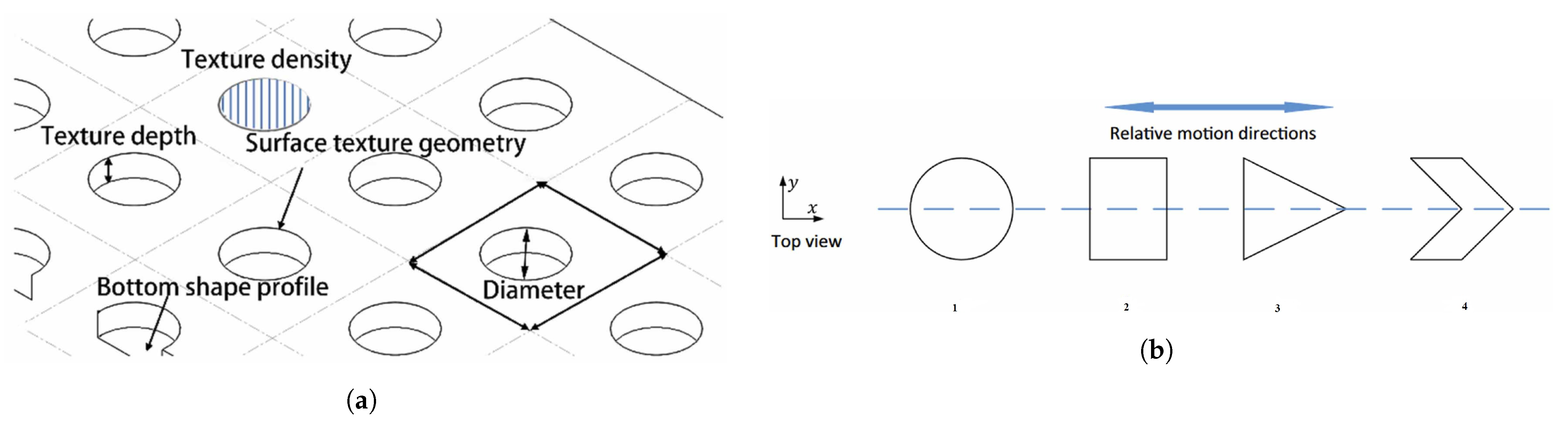
  159. Zhang, H.; Hua, M.; Dong, G.Z.; Zhang, D.Y.; Chen, W.J.; Dong, G.N. Optimization of texture shape based on genetic algorithm under unidirectional sliding. Tribol. Int. 2017, 115, 222–232. [Google Scholar] [CrossRef]
  160. Lu, P.; Wood, R.J.; Gee, M.G.; Wang, L.; Pfleging, W. The use of anisotropic texturing for control of directional friction. Tribol. Int. 2017, 113, 169–181. [Google Scholar] [CrossRef] [Green Version]
  161. Yu, H.; Deng, H.; Huang, W.; Wang, X. The effect of dimple shapes on friction of parallel surfaces. Proc. Inst. Mech. Eng. Part J J. Eng. Tribol. 2011, 225, 693–703. [Google Scholar] [CrossRef]
  162. Ullah, M.Z.; Rizwan, M.; Raza, A.; Ahmed, A.; Abid, M. Effect of dimple shape and depth on tribological performance of textured surface. In Proceedings of the 2021 International Bhurban Conference on Applied Sciences and Technologies (IBCAST), Islamabad, Pakistan, 12–16 January 2021; pp. 719–725. [Google Scholar]
  163. Nanbu, T.; Ren, N.; Yasuda, Y.; Zhu, D.; Wang, Q.J. Micro-textures in concentrated conformal-contact lubrication: Effects of texture bottom shape and surface relative motion. Tribol. Lett. 2008, 29, 241–252. [Google Scholar] [CrossRef]
  164. Babu, P.V.; Ismail, S.; Ben, B.S. Experimental and numerical studies of positive texture effect on friction reduction of sliding contact under mixed lubrication. Proc. Inst. Mech. Eng. Part J J. Eng. Tribol. 2021, 235, 360–375. [Google Scholar] [CrossRef]
  165. Zhang, H.; Hua, M.; Dong, G.n.; Zhang, D.y.; Chin, K.S. A mixed lubrication model for studying tribological behaviors of surface texturing. Tribol. Int. 2016, 93, 583–592. [Google Scholar] [CrossRef]
  166. Wang, J.; Yan, Z.; Fang, X.; Shen, Z.; Pan, X. Observation and experimental investigation on cavitation effect of friction pair surface texture. Lubr. Sci. 2020, 32, 404–414. [Google Scholar] [CrossRef]
  167. Hua, X.; Puoza, J.C.; Zhang, P.; Xie, X.; Yin, B. Experimental analysis of grease friction properties on sliding textured surfaces. Lubricants 2017, 5, 42. [Google Scholar] [CrossRef] [Green Version]
  168. Schneider, J.; Braun, D.; Greiner, C. Laser textured surfaces for mixed lubrication: Influence of aspect ratio, textured area and dimple arrangement. Lubricants 2017, 5, 32. [Google Scholar] [CrossRef] [Green Version]
  169. Costa, H.; Hutchings, I.M. Some innovative surface texturing techniques for tribological purposes. Proc. Inst. Mech. Eng. Part J J. Eng. Tribol. 2015, 229, 429–448. [Google Scholar] [CrossRef] [Green Version]
  170. Roy, T.; Choudhury, D.; Mamat, A.B.; Pingguan-Murphy, B. Fabrication and characterization of micro-dimple array on Al2O3 surfaces by using a micro-tooling. Ceram. Int. 2014, 40, 2381–2388. [Google Scholar] [CrossRef]
  171. Jain, A.; Kumari, N.; Jagadevan, S.; Bajpai, V. Surface properties and bacterial behavior of micro conical dimple textured Ti6Al4V surface through micro-milling. Surfaces Interfaces 2020, 21, 100714. [Google Scholar] [CrossRef]
  172. Lee, H.; Yi, A.; Choi, J.; Ko, D.H.; Kim, H.J. Texturing of polydimethylsiloxane surface for anti-reflective films with super-hydrophobicity in solar cell application. Appl. Surf. Sci. 2022, 584, 152625. [Google Scholar] [CrossRef]
  173. Shi, L.; Fang, Y.; Dai, Q.; Huang, W.; Wang, X. Surface texturing on SiC by multiphase jet machining with microdiamond abrasives. Mater. Manuf. Process. 2018, 33, 1415–1421. [Google Scholar] [CrossRef]
  174. Chatterjee, S.; Shariff, S.; Datta Majumdar, J.; Roy Choudhury, A. Development of nano-structured Al2O3-TiB2-TiN coatings by combined SHS and laser surface alloying. Int. J. Adv. Manuf. Technol. 2008, 38, 938–943. [Google Scholar] [CrossRef]
  175. Wos, S.; Koszela, W.; Pawlus, P. Comparing tribological effects of various chevron-based surface textures under lubricated unidirectional sliding. Tribol. Int. 2020, 146, 106205. [Google Scholar] [CrossRef]
  176. Ryk, G.; Etsion, I. Testing piston rings with partial laser surface texturing for friction reduction. Wear 2006, 261, 792–796. [Google Scholar] [CrossRef]
  177. Mao, B.; Siddaiah, A.; Liao, Y.; Menezes, P.L. Laser surface texturing and related techniques for enhancing tribological performance of engineering materials: A review. J. Manuf. Process. 2020, 53, 153–173. [Google Scholar] [CrossRef]
  178. Pei, S.; Xu, H.; Yun, M.; Shi, F.; Hong, J. Effects of surface texture on the lubrication performance of the floating ring bearing. Tribol. Int. 2016, 102, 143–153. [Google Scholar] [CrossRef]
  179. Ibatan, T.; Uddin, M.; Chowdhury, M. Recent development on surface texturing in enhancing tribological performance of bearing sliders. Surf. Coat. Technol. 2015, 272, 102–120. [Google Scholar] [CrossRef]
  180. Amouzgar, K.; Bandaru, S.; Andersson, T.; Ng, A.H. Metamodel-based multi-objective optimization of a turning process by using finite element simulation. Eng. Optim. 2020, 52, 1261–1278. [Google Scholar] [CrossRef] [Green Version]
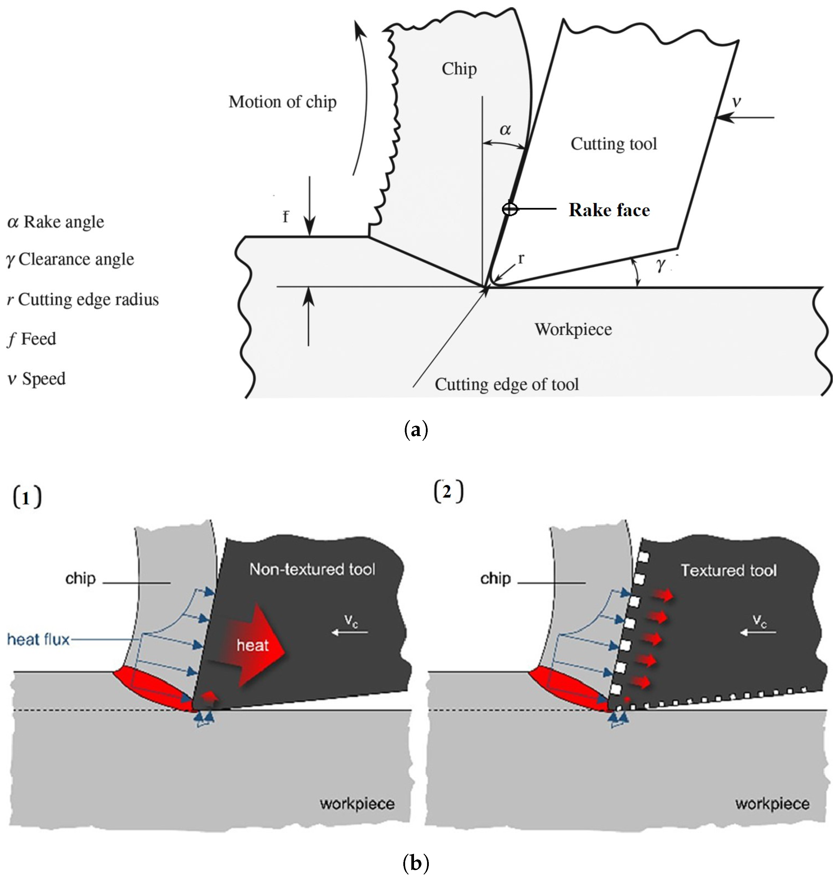
  181. Özel, T.; Biermann, D.; Enomoto, T.; Mativenga, P. Structured and textured cutting tool surfaces for machining applications. CIRP Ann. 2021, 70, 495–518. [Google Scholar] [CrossRef]
  182. Bijani, D.; Deladi, E.L.; Akchurin, A.; De Rooij, M.B.; Schipper, D.J. The influence of surface texturing on the frictional behaviour of parallel sliding lubricated surfaces under conditions of mixed lubrication. Lubricants 2018, 6, 91. [Google Scholar] [CrossRef] [Green Version]
  183. Borghi, A.; Gualtieri, E.; Marchetto, D.; Moretti, L.; Valeri, S. Tribological effects of surface texturing on nitriding steel for high-performance engine applications. Wear 2008, 265, 1046–1051. [Google Scholar] [CrossRef]
  184. Varenberg, M.; Halperin, G.; Etsion, I. Different aspects of the role of wear debris in fretting wear. Wear 2002, 252, 902–910. [Google Scholar] [CrossRef]
  185. Volchok, A.; Halperin, G.; Etsion, I. The effect of surface regular microtopography on fretting fatigue life. Wear 2002, 253, 509–515. [Google Scholar] [CrossRef]
  186. Wu, Z.; Bao, H.; Xing, Y.; Liu, L. Tribological characteristics and advanced processing methods of textured surfaces: A review. Int. J. Adv. Manuf. Technol. 2021, 114, 1241–1277. [Google Scholar] [CrossRef]
  187. Xing, Y.; Deng, J.; Feng, X.; Yu, S. Effect of laser surface texturing on Si3N4/TiC ceramic sliding against steel under dry friction. Mater. Des. 1980–2015 2013, 52, 234–245. [Google Scholar] [CrossRef]
  188. Rosenkranz, A.; Reinert, L.; Gachot, C.; Mücklich, F. Alignment and wear debris effects between laser-patterned steel surfaces under dry sliding conditions. Wear 2014, 318, 49–61. [Google Scholar] [CrossRef]
  189. Bathe, R.; Sai Krishna, V.; Nikumb, S.; Padmanabham, G. Laser surface texturing of gray cast iron for improving tribological behavior. Appl. Phys. A 2014, 117, 117–123. [Google Scholar] [CrossRef]
  190. Niu, Y.; Pang, X.; Yue, S.; Shangguan, B.; Zhang, Y. The friction and wear behavior of laser textured surfaces in non-conformal contact under starved lubrication. Wear 2021, 476, 203723. [Google Scholar] [CrossRef]
  191. Childs, T.H.; Maekawa, K.; Obikawa, T.; Yamane, Y. Metal Machining: Theory and Applications; Butterworth-Heinemann: Waltham, MA, USA, 2000. [Google Scholar]
  192. Durairaj, S.; Guo, J.; Aramcharoen, A.; Castagne, S. An experimental study into the effect of micro-textures on the performance of cutting tool. Int. J. Adv. Manuf. Technol. 2018, 98, 1011–1030. [Google Scholar] [CrossRef]
  193. Jianxin, D.; Ze, W.; Yunsong, L.; Ting, Q.; Jie, C. Performance of carbide tools with textured rake-face filled with solid lubricants in dry cutting processes. Int. J. Refract. Met. Hard Mater. 2012, 30, 164–172. [Google Scholar] [CrossRef]
  194. Lo, S.W.; Wilson, W.R.D. A Theoretical Model of Micro-Pool Lubrication in Metal Forming. J. Tribol. 1999, 121, 731–738. [Google Scholar] [CrossRef]
  195. Gajrani, K.K.; Suresh, S.; Sankar, M.R. Environmental friendly hard machining performance of uncoated and MoS2 coated mechanical micro-textured tungsten carbide cutting tools. Tribol. Int. 2018, 125, 141–155. [Google Scholar] [CrossRef]
  196. Sharma, V.; Pandey, P.M. Comparative Study of Turning of 4340 Hardened Steel with Hybrid Textured Self-Lubricating Cutting Inserts. Mater. Manuf. Process. 2016, 31, 1904–1916. [Google Scholar] [CrossRef]
  197. Xing, Y.; Deng, J.; Li, S.; Yue, H.; Meng, R.; Gao, P. Cutting performance and wear characteristics of Al2O3/TiC ceramic cutting tools with WS2/Zr soft-coatings and nano-textures in dry cutting. Wear 2014, 318, 12–26. [Google Scholar] [CrossRef]
  198. Fu, J.; Xu, C.; Ma, D.; Zhu, X.; Cheng, D.; Yan, Z.; Ma, C.; Liu, G.; Fu, Y. Tribological properties and releasing behavior of solid lubricant WS2 in the dimples on cylinder liner surface of diesel engine. Tribol. Int. 2021, 158, 106936. [Google Scholar] [CrossRef]
  199. Li, X.; Yan, C.; Liu, Q.; Dong, G. An In Situ Fabrication of CuGa2 Film on Copper Surface With Improved Tribological Properties. J. Tribol. 2021, 143, 071404. [Google Scholar] [CrossRef]
  200. Sugihara, T.; Enomoto, T. Development of a cutting tool with a nano/micro-textured surface—Improvement of anti-adhesive effect by considering the texture patterns. Precis. Eng. 2009, 33, 425–429. [Google Scholar] [CrossRef]
  201. Kawasegi, N.; Sugimori, H.; Morita, N.; Xue, M.C. Atmosphere effects on the machinability of cutting tools with micro-and nanoscale textures. In Advanced Materials Research; Trans Tech Publications Ltd.: Zurich, Switzerland, 2011; Volume 325, pp. 333–338. [Google Scholar]
  202. Kim, D.M.; Lee, I.; Kim, S.K.; Kim, B.H.; Park, H.W. Influence of a micropatterned insert on characteristics of the tool–workpiece interface in a hard turning process. J. Mater. Process. Technol. 2016, 229, 160–171. [Google Scholar] [CrossRef]
  203. Deng, J.; Song, W.; Zhang, H.; Yan, P.; Liu, A. Friction and wear behaviors of the carbide tools embedded with solid lubricants in sliding wear tests and in dry cutting processes. Wear 2011, 270, 666–674. [Google Scholar] [CrossRef]
  204. Yang, Y.; Su, Y.; Li, L.; He, N.; Zhao, W. Performance of cemented carbide tools with microgrooves in Ti-6Al-4V titanium alloy cutting. Int. J. Adv. Manuf. Technol. 2015, 76, 1731–1738. [Google Scholar] [CrossRef]
  205. Lian, Y.; Deng, J.; Yan, G.; Cheng, H.; Zhao, J. Preparation of tungsten disulfide (WS2) soft-coated nano-textured self-lubricating tool and its cutting performance. Int. J. Adv. Manuf. Technol. 2013, 68, 2033–2042. [Google Scholar] [CrossRef]
  206. Xing, Y.; Deng, J.; Zhao, J.; Zhang, G.; Zhang, K. Cutting performance and wear mechanism of nanoscale and microscale textured Al2O3/TiC ceramic tools in dry cutting of hardened steel. Int. J. Refract. Met. Hard Mater. 2014, 43, 46–58. [Google Scholar] [CrossRef]
  207. Zhang, K.; Deng, J.; Ding, Z.; Guo, X.; Sun, L. Improving dry machining performance of TiAlN hard-coated tools through combined technology of femtosecond laser-textures and WS2 soft-coatings. J. Manuf. Process. 2017, 30, 492–501. [Google Scholar] [CrossRef]
  208. Sharma, V.; Pandey, P.M. Recent advances in turning with textured cutting tools: A review. J. Clean. Prod. 2016, 137, 701–715. [Google Scholar] [CrossRef]
  209. Whitney, E.D. Ceramic Cutting Tools: Materials, Development and Performance; William Andrew: Norwich, NY, USA, 2012; pp. 13–27. [Google Scholar]
  210. Aruna, M.; Dhanalakshmi, V.; Mohan, S. Wear analysis of ceramic cutting tools in finish turning of Inconel 718. Int. J. Eng. Sci. Technol. 2010, 2, 4253–4262. [Google Scholar]
  211. Kumar, A.S.; Durai, A.R.; Sornakumar, T. Wear behaviour of alumina based ceramic cutting tools on machining steels. Tribol. Int. 2006, 39, 191–197. [Google Scholar] [CrossRef]
  212. Zhu, D.; Zhang, X.; Ding, H. Tool wear characteristics in machining of nickel-based superalloys. Int. J. Mach. Tools Manuf. 2013, 64, 60–77. [Google Scholar] [CrossRef]
  213. Rao, D.N.; Krishna, P.V. The influence of solid lubricant particle size on machining parameters in turning. Int. J. Mach. Tools Manuf. 2008, 48, 107–111. [Google Scholar]
  214. Reddy, N.S.K.; Nouari, M. A comparative study on the role of solid lubricant for improving tribological properties in turning process. In Proceedings of the 37th International Conference on Metallurgical Coatings and Thin Films, San Diego, CA, USA, 26–30 April 2010. [Google Scholar]
  215. Reddy, N.S.K.; Nouari, M. The influence of solid lubricant for improving tribological properties in turning process. Lubr. Sci. 2011, 23, 49–59. [Google Scholar] [CrossRef]
  216. Divya, C.; Suvarna Raju, L.; Singaravel, B. Experimental investigation on solid lubricant supply methodology in turning process. Mater. Manuf. Process. 2021, 36, 1781–1788. [Google Scholar] [CrossRef]
  217. Xavior, M.A.; Adithan, M. Determining the influence of cutting fluids on tool wear and surface roughness during turning of AISI 304 austenitic stainless steel. J. Mater. Process. Technol. 2009, 209, 900–909. [Google Scholar] [CrossRef]
  218. Onuoha, O.J.; Abu, J.O.; Lawal, S.A.; Mudiare, E.; Adeyemi, M.B. Determining the effect of cutting fluids on surface roughness in turning AISI 1330 alloy steel using Taguchi method. J. Mod. Mech. Eng. 2016, 6, 51–59. [Google Scholar] [CrossRef] [Green Version]
  219. Moura, R.R.; da Silva, M.B.; Machado, Á.R.; Sales, W.F. The effect of application of cutting fluid with solid lubricant in suspension during cutting of Ti-6Al-4V alloy. Wear 2015, 332, 762–771. [Google Scholar] [CrossRef]
  220. Sharma, A.K.; Tiwari, A.K.; Dixit, A.R.; Singh, R.K. Measurement of machining forces and surface roughness in turning of AISI 304 steel using alumina-MWCNT hybrid nanoparticles enriched cutting fluid. Measurement 2020, 150, 107078. [Google Scholar] [CrossRef]
  221. Maruda, R.W.; Krolczyk, G.M.; Nieslony, P.; Wojciechowski, S.; Michalski, M.; Legutko, S. The influence of the cooling conditions on the cutting tool wear and the chip formation mechanism. J. Manuf. Process. 2016, 24, 107–115. [Google Scholar] [CrossRef]
  222. Gajrani, K.K.; Suvin, P.S.; Kailas, S.V.; Sankar, M.R. Hard machining performance of indigenously developed green cutting fluid using flood cooling and minimum quantity cutting fluid. J. Clean. Prod. 2019, 206, 108–123. [Google Scholar] [CrossRef]
  223. Banerjee, N.; Sharma, A. Identification of a friction model for minimum quantity lubrication machining. J. Clean. Prod. 2014, 83, 437–443. [Google Scholar] [CrossRef]
  224. Liu, Z.; Chen, M.; An, Q. Investigation of friction in end-milling of Ti-6Al-4V under different green cutting conditions. Int. J. Adv. Manuf. Technol. 2015, 78, 1181–1192. [Google Scholar] [CrossRef]
  225. Gajrani, K.K.; Suvin, P.S.; Kailas, S.V.; Mamilla, R.S. Thermal, rheological, wettability and hard machining performance of MoS2 and WS2based minimum quantity hybrid nano-green cutting fluids. J. Mater. Process. Technol. 2019, 266, 125–139. [Google Scholar] [CrossRef]
  226. Faizal, M.; Saidur, R.; Mekhilef, S.; Faizal, M. Potential of size reduction of flat-plate solar collectors when applying Al2O3 nanofluid. In Advanced Materials Research; Trans Tech Publications Ltd.: Zurich, Switzerland, 2014; Volume 832, pp. 149–153. [Google Scholar]
  227. Lv, T.; Huang, S.; Liu, E.; Ma, Y.; Xu, X. Tribological and machining characteristics of an electrostatic minimum quantity lubrication (EMQL) technology using graphene nano-lubricants as cutting fluids. J. Manuf. Process. 2018, 34, 225–237. [Google Scholar] [CrossRef]
  228. De Portu, G.; Guicciardi, S.; Melandri, C.; Monteverde, F. Wear behaviour of Al2O3–Mo and Al2O3–Nb composites. Wear 2007, 262, 1346–1352. [Google Scholar] [CrossRef]
  229. GuoChen, D.U.; Ying, C.H.; Wei, Z. Effects of solid lubricants on hard turning. In Proceedings of the 2nd International Conference on Electronic & Mechanical Engineering and Information Technology; Atlantis Press: Paris, France, 2012; pp. 1146–1149. [Google Scholar]
  230. Trent, E.M.; Wright, P.K. Metal Cutting; Butterworth-Heinemann: Oxford, UK, 2000. [Google Scholar]
  231. Chen, J.; Yu, W.; Zuo, Z.; Li, Y.; Chen, D.; An, Q.; Wang, H.; Chen, M. Tribological properties and tool wear in milling of in-situ TiB2/7075 Al composite under various cryogenic MQL conditions. Tribol. Int. 2021, 160, 107021. [Google Scholar] [CrossRef]
  232. Şap, S.; Usca, Ü.A.; Uzun, M.; Kuntoğlu, M.; Salur, E.; Pimenov, D.Y. Investigation of the effects of cooling and lubricating strategies on tribological characteristics in machining of hybrid composites. Lubricants 2022, 10, 63. [Google Scholar] [CrossRef]
  233. Zhang, S.; Li, J.F.; Wang, Y.W. Tool life and cutting forces in end milling Inconel 718 under dry and minimum quantity cooling lubrication cutting conditions. J. Clean. Prod. 2012, 32, 81–87. [Google Scholar] [CrossRef]
  234. Velmurugan, V.; Manimaran, G. Effect of MoS2 solid lubricant on the tribological aspects of Ti-6Al-4V alloy in drilling operations. Mater. Today Proc. 2022, 62, 925–932. [Google Scholar] [CrossRef]
  235. Nalb, S.C.; Pamidimukkala, K.; Gunda, R.K.; Paturi, U.M. Effect of minimum quantity solid lubrication (MQSL) parameters on cutting force and temperature during turning of EN31 steel. Mater. Today Proc. 2021, 38, 3314–3319. [Google Scholar]
  236. Dang, J.; Liu, G.; Chen, Y.; An, Q.; Ming, W.; Chen, M. Experimental investigation on machinability of DMLS Ti6Al4V under dry drilling process. Mater. Manuf. Process. 2019, 34, 749–758. [Google Scholar] [CrossRef]
  237. Barry, J.; Byrne, G.; Lennon, D. Observations on chip formation and acoustic emission in machining Ti–6Al–4V alloy. Int. J. Mach. Tools Manuf. 2001, 41, 1055–1070. [Google Scholar] [CrossRef]
  238. Wang, Q.; Lu, C.; Ye, G.; Dai, L. Modelling the tuned criticality in stick-slip friction during metal cutting. Model. Simul. Mater. Sci. Eng. 2015, 23, 055013. [Google Scholar] [CrossRef] [Green Version]
  239. Kouam, J.; Songmene, V.; Balazinski, M.; Hendrick, P. Effects of minimum quantity lubricating (MQL) conditions on machining of 7075-T6 aluminum alloy. Int. J. Adv. Manuf. Technol. 2015, 79, 1325–1334. [Google Scholar] [CrossRef]
  240. Yıldırım, Ç.V.; Kıvak, T.; Sarıkaya, M.; Şirin, Ş. Evaluation of tool wear, surface roughness/topography and chip morphology when machining of Ni-based alloy 625 under MQL, cryogenic cooling and CryoMQL. J. Mater. Res. Technol. 2020, 9, 2079–2092. [Google Scholar] [CrossRef]
  241. Aslan, A. Optimization and analysis of process parameters for flank wear, cutting forces and vibration in turning of AISI 5140: A comprehensive study. Measurement 2020, 163, 107959. [Google Scholar] [CrossRef]
  242. Kuntoğlu, M.; Gupta, M.K.; Aslan, A.; Salur, E.; Garcia-Collado, A. Influence of tool hardness on tool wear, surface roughness and acoustic emissions during turning of AISI 1050. Surf. Topogr. Metrol. Prop. 2022, 10, 015016. [Google Scholar] [CrossRef]
  243. Wang, Y.; Zou, B.; Wang, J.; Wu, Y.; Huang, C. Effect of the progressive tool wear on surface topography and chip formation in micro-milling of Ti–6Al–4V using Ti (C7N3)-based cermet micro-mill. Tribol. Int. 2020, 141, 105900. [Google Scholar] [CrossRef]
  244. Arrazola, P.; Özel, T.; Umbrello, D.; Davies, M.; Jawahir, I. Recent advances in modeling of metal machining processes. Cirp Ann. 2013, 62, 695–718. [Google Scholar] [CrossRef]
  245. Jawahir, I.; Brinksmeier, E.; M’saoubi, R.; Aspinwall, D.; Outeiro, J.; Meyer, D.; Umbrello, D.; Jayal, A. Surface integrity in material removal processes: Recent advances. CIRP Ann. 2011, 60, 603–626. [Google Scholar] [CrossRef]
  246. Davoudinejad, A.; Chiappini, E.; Tirelli, S.; Annoni, M.; Strano, M. Finite element simulation and validation of chip formation and cutting forces in dry and cryogenic cutting of Ti–6Al–4V. Procedia Manuf. 2015, 1, 728–739. [Google Scholar] [CrossRef] [Green Version]
  247. Pu, Z.; Umbrello, D.; Dillon, O., Jr.; Jawahir, I. Finite element simulation of residual stresses in cryogenic machining of AZ31B Mg alloy. Procedia Cirp 2014, 13, 282–287. [Google Scholar] [CrossRef] [Green Version]
  248. Mohammadpour, M.; Razfar, M.; Saffar, R.J. Numerical investigating the effect of machining parameters on residual stresses in orthogonal cutting. Simul. Model. Pract. Theory 2010, 18, 378–389. [Google Scholar] [CrossRef]
  249. Ali, M.H.; Khidhir, B.A.; Ansari, M.; Mohamed, B. FEM to predict the effect of feed rate on surface roughness with cutting force during face milling of titanium alloy. Hbrc J. 2013, 9, 263–269. [Google Scholar] [CrossRef] [Green Version]
  250. Korkut, I.; Donertas, M. The influence of feed rate and cutting speed on the cutting forces, surface roughness and tool–chip contact length during face milling. Mater. Des. 2007, 28, 308–312. [Google Scholar] [CrossRef]
  251. Rotella, G.; Umbrello, D. Finite element modeling of microstructural changes in dry and cryogenic cutting of Ti6Al4V alloy. Cirp Ann. 2014, 63, 69–72. [Google Scholar] [CrossRef]
  252. Shet, C.; Deng, X.; Bayoumi, A.E. Finite element simulation of high-pressure water-jet assisted metal cutting. Int. J. Mech. Sci. 2003, 45, 1201–1228. [Google Scholar] [CrossRef]
  253. Yen, Y.C.; Söhner, J.; Lilly, B.; Altan, T. Estimation of tool wear in orthogonal cutting using the finite element analysis. J. Mater. Process. Technol. 2004, 146, 82–91. [Google Scholar] [CrossRef]
  254. Shih, A.J. Finite element analysis of the rake angle effects in orthogonal metal cutting. Int. J. Mech. Sci. 1995, 38, 1–17. [Google Scholar] [CrossRef]
  255. Özel, T. Computational modeling of 3D turning: Influence of edge micro-geometry on forces, stresses, friction and tool wear in PcBN tooling. J. Mater. Process. Technol. 2009, 209, 5167–5177. [Google Scholar] [CrossRef]
  256. Moriwaki, T.; Sugimura, N.; Luan, S. Combined stress, material flow and heat analysis of orthogonal micromachining of copper. CIRP Ann. 1993, 42, 75–78. [Google Scholar] [CrossRef]
  257. Arrazola, P.; Ozel, T. Numerical modeling of 3D hard turning using arbitrary Lagrangian Eulerian finite element method. Int. J. Mach. Mach. Mater. 2008, 4, 14–25. [Google Scholar]
  258. Demiral, M.; Roy, A.; Silberschmidt, V.V. Strain-gradient crystal-plasticity modeling of micro-cutting of bcc single crystal. Meccanica 2016, 51, 371–381. [Google Scholar] [CrossRef] [Green Version]
  259. Zahedi, S.A.; Demiral, M.; Roy, A.; Silberschmidt, V.V. FE/SPH modeling of orthogonal micro-machining of fcc single crystal. Comput. Mater. Sci. 2013, 78, 104–109. [Google Scholar] [CrossRef] [Green Version]
  260. Ceretti, E.; Fallböhmer, P.; Wu, W.; Altan, T. Application of 2D FEM to chip formation in orthogonal cutting. J. Mater. Process. Technol. 1996, 59, 169–180. [Google Scholar] [CrossRef]
  261. Chen, L.; El-Wardany, T.; Harris, W. Modelling the effects of flank wear land and chip formation on residual stresses. CIRP Ann. 2004, 53, 95–98. [Google Scholar] [CrossRef]
  262. Carroll, J.T., III; Strenkowski, J.S. Finite element models of orthogonal cutting with application to single point diamond turning. Int. J. Mech. Sci. 1988, 30, 899–920. [Google Scholar] [CrossRef]
  263. Lin, Z.C.; Pan, W.C. A thermoelastic-plastic large deformation model for orthogonal cutting with tool flank wear—Part I: Computational procedures. Int. J. Mech. Sci. 1993, 35, 829–840. [Google Scholar] [CrossRef]
  264. Zhang, L. On the separation criteria in the simulation of orthogonal metal cutting using the finite element method. J. Mater. Process. Technol. 1999, 89, 273–278. [Google Scholar] [CrossRef]
  265. Movahhedy, M.; Gadala, M.; Altintas, Y. Simulation of the orthogonal metal cutting process using an arbitrary Lagrangian–Eulerian finite-element method. J. Mater. Process. Technol. 2000, 103, 267–275. [Google Scholar] [CrossRef]
  266. Bäker, M.; Rösler, J.; Siemers, C. A finite element model of high speed metal cutting with adiabatic shearing. Comput. Struct. 2002, 80, 495–513. [Google Scholar] [CrossRef]
  267. Sekhon, G.; Chenot, J. Numerical simulation of continuous chip formation during non-steady orthogonal cutting. Eng. Comput. 1993, 10, 31–48. [Google Scholar] [CrossRef]
  268. Shih, A.J.; Yang, H.T. Experimental and finite element predictions of residual stresses due to orthogonal metal cutting. Int. J. Numer. Methods Eng. 1993, 36, 1487–1507. [Google Scholar] [CrossRef]
  269. Zanger, F.; Boev, N.; Schulze, V. Novel approach for 3D simulation of a cutting process with adaptive remeshing technique. Procedia CIRP 2015, 31, 88–93. [Google Scholar] [CrossRef] [Green Version]
  270. Kadin, Y.; Mazaheri, M.; Zolotarevskiy, V.; Vieillard, C.; Hadfield, M. Finite elements based approaches for the modeling of radial crack formation upon Vickers indentation in silicon nitride ceramics. J. Eur. Ceram. Soc. 2019, 39, 4011–4022. [Google Scholar] [CrossRef]
  271. Zhang, T.; Jiang, F.; Yan, L.; Xu, X. FEM modeling of the relationship between the high-temperature hardness and high-temperature, quasi-static compression experiment. Materials 2017, 11, 34. [Google Scholar] [CrossRef] [Green Version]
  272. Wang, D.; Zhao, J.; Xue, C.; Cao, Y. Finite element simulation of Vickers micro-indentation test of micro-nano-composite ceramic tool materials based on microstructure model. Int. J. Refract. Met. Hard Mater. 2016, 58, 34–41. [Google Scholar] [CrossRef]
  273. Bootchai, S.; Noraphaiphipaksa, N.; Taweejun, N.; Manonukul, A.; Kanchanomai, C. Determination of localized stress–strain behavior of fused silica: Inverse numerical analysis from nanoindentation test. Proc. Inst. Mech. Eng. Part L J. Mater. Des. Appl. 2021, 235, 456–466. [Google Scholar] [CrossRef]
  274. Chen, Z.; Wang, X.; Atkinson, A.; Brandon, N. Spherical indentation of porous ceramics: Elasticity and hardness. J. Eur. Ceram. Soc. 2016, 36, 1435–1445. [Google Scholar] [CrossRef] [Green Version]
  275. Melkote, S.; Liang, S.Y.; Ozel, T.; Jawahir, I.; Stephenson, D.A.; Wang, B. A review of advances in modeling of conventional machining processes: From merchant to the present. J. Manuf. Sci. Eng. 2022, 144, 110801. [Google Scholar] [CrossRef]
  276. Ducobu, F.; Rivière-Lorphèvre, E.; Filippi, E. Material constitutive model and chip separation criterion influence on the modeling of Ti6Al4V machining with experimental validation in strictly orthogonal cutting condition. Int. J. Mech. Sci. 2016, 107, 136–149. [Google Scholar] [CrossRef]
  277. Mahnama, M.; Movahhedy, M. Application of FEM simulation of chip formation to stability analysis in orthogonal cutting process. J. Manuf. Process. 2012, 14, 188–194. [Google Scholar] [CrossRef]
  278. Priyadarshini, A.; Pal, S.K.; Samantaray, A.K. Finite element modeling of chip formation in orthogonal machining. In Statistical and Computational Techniques in Manufacturing; Springer: Berlin/Heidelberg, Germany, 2012; pp. 101–144. [Google Scholar]
  279. Klamecki, B.E. INcipient Chip Formation In Metal Cutting–A Three-Dimension Finite-Element Analysis; University of Illinois at Urbana-Champaign: Champaign, IL, USA, 1973. [Google Scholar]
  280. Usui, E.; Hirota, A.; Masuko, M. Analytical Prediction of Three Dimensional Cutting Process—Part 1: Basic Cutting Model and Energy Approach. J. Eng. Ind. 1978, 100, 222–228. [Google Scholar] [CrossRef]
  281. Usui, E.; Hirota, A. Analytical Prediction of Three Dimensional Cutting Process—Part 2: Chip Formation and Cutting Force with Conventional Single-Point Tool. J. Eng. Ind. 1978, 100, 229–235. [Google Scholar] [CrossRef]
  282. Usui, E.; Shirakashi, T.; Kitagawa, T. Analytical Prediction of Three Dimensional Cutting Process—Part 3: Cutting Temperature and Crater Wear of Carbide Tool. J. Eng. Ind. 1978, 100, 236–243. [Google Scholar] [CrossRef]
  283. Puls, H.; Klocke, F.; Lung, D. Experimental investigation on friction under metal cutting conditions. Wear 2014, 310, 63–71. [Google Scholar] [CrossRef]
  284. Athavale, S.M.; Strenkowski, J.S. Material Damage-Based Model for Predicting Chip-Breakability. J. Manuf. Sci. Eng. 1997, 119, 675–680. [Google Scholar] [CrossRef]
  285. Strenkowski, J.S.; Shih, A.J.; Lin, J.C. An analytical finite element model for predicting three-dimensional tool forces and chip flow. Int. J. Mach. Tools Manuf. 2002, 42, 723–731. [Google Scholar] [CrossRef]
  286. Wang, C.C. Finite element simulation for forging process using Euler’s fixed meshing method. In Materials Science Forum; Trans Tech Publications Ltd.: Zurich, Switzerland, 2008; Volume 575, pp. 1139–1144. [Google Scholar]
  287. Donea, J.; Huerta, A.; Ponthot, J.P.; Rodríguez-Ferran, A. Arbitrary L agrangian–E ulerian Methods. In Encyclopedia of Computational Mechanics; Wiley: Hoboken, NJ, Canada, 2004. [Google Scholar]
  288. Hu, F.; Li, D. Modelling and simulation of milling forces using an arbitrary Lagrangian–Eulerian finite element method and support vector regression. J. Optim. Theory Appl. 2012, 153, 461–484. [Google Scholar] [CrossRef]
  289. Arrazola, P.J. Investigations on the effects of friction modeling in finite element simulation of machining. Int. J. Mech. Sci. 2010, 52, 31–42. [Google Scholar] [CrossRef]
  290. Movahhedy, M.; Altintas, Y.; Gadala, M.S. Numerical analysis of metal cutting with chamfered and blunt tools. J. Manuf. Sci. Eng. 2002, 124, 178–188. [Google Scholar] [CrossRef]
  291. Olovsson, L.; Nilsson, L.; Simonsson, K. An ALE formulation for the solution of two-dimensional metal cutting problems. Comput. Struct. 1999, 72, 497–507. [Google Scholar] [CrossRef]
  292. Xie, L.J.; Schmidt, J.; Schmidt, C.; Biesinger, F. 2D FEM estimate of tool wear in turning operation. Wear 2005, 258, 1479–1490. [Google Scholar] [CrossRef]
  293. Attanasio, A.; Ceretti, E.; Rizzuti, S.; Umbrello, D.; Micari, F. 3D finite element analysis of tool wear in machining. CIRP Ann. 2008, 57, 61–64. [Google Scholar] [CrossRef]
  294. Attanasio, A.; Ceretti, E.; Giardini, C.; Filice, L.; Umbrello, D. Criterion to evaluate diffusive wear in 3D simulations when turning AISI 1045 steel. Int. J. Mater. Form. 2008, 1, 495–498. [Google Scholar] [CrossRef]
  295. Attanasio, A.; Ceretti, E.; Fiorentino, A.; Cappellini, C.; Giardini, C. Investigation and FEM-based simulation of tool wear in turning operations with uncoated carbide tools. Wear 2010, 269, 344–350. [Google Scholar] [CrossRef]
  296. Mir, A.; Luo, X.; Sun, J. The investigation of influence of tool wear on ductile to brittle transition in single point diamond turning of silicon. Wear 2016, 364, 233–243. [Google Scholar] [CrossRef] [Green Version]
  297. Popovici, V.; Pavalache, A.C.; Vasile, M.; Voiculescu, I.; Stanciu, E.M.; Pausan, D. Finite element method for simulating the Vickers Hardness Test. In Applied Mechanics and Materials; Trans Tech Publications Ltd.: Zurich, Switzerland, 2014; Volume 555, pp. 419–424. [Google Scholar]
  298. Bouzakis, K.D.; Michailidis, N.; Skordaris, G. Hardness determination by means of a FEM-supported simulation of nanoindentation and applications in thin hard coatings. Surf. Coat. Technol. 2005, 200, 867–871. [Google Scholar] [CrossRef]
  299. Skliarov, V.; Zalohin, M.; Dovzhenko, J. Application of the FEM for modeling and prediction of the relationship between the hardness and stress of the deformed body. In Behavior and Mechanics of Multifunctional Materials and Composites 2017; SPIE: Bellingham, WA, USA, 2017; Volume 10165, pp. 287–294. [Google Scholar]
  300. Choi, Y.; Park, J.; Kim, B.; Choi, J.; Min, B. Estimation of relation between effective strain and hardness by rigid-plastic FEM. Met. Mater. 2000, 6, 111–116. [Google Scholar] [CrossRef]
  301. Shaw, M.C.; Cookson, J. Metal Cutting Principles; Oxford University Press: New York, NY, USA, 2005; Volume 2. [Google Scholar]
  302. Hamada, S.; Nakanishi, M.; Moriyama, T.; Noguchi, H. Re-Examination of correlation between hardness and tensile properties by numerical analysis. Exp. Mech. 2017, 57, 773–781. [Google Scholar] [CrossRef]
  303. Gurson, A.L. Continuum Theory of Ductile Rupture by Void Nucleation and Growth: Part I—Yield Criteria and Flow Rules for Porous Ductile Media. J. Eng. Mater. Technol. 1977, 99, 2–15. [Google Scholar] [CrossRef]
  304. Tvergaard, V. Influence of voids on shear band instabilities under plane strain conditions. Int. J. Fract. 1981, 17, 389–407. [Google Scholar] [CrossRef]
  305. Bhattacharya, A.; Nix, W. Finite element simulation of indentation experiments. Int. J. Solids Struct. 1988, 24, 881–891. [Google Scholar] [CrossRef]
  306. Mesarovic, S.D.; Fleck, N.A. Spherical indentation of elastic–plastic solids. Proc. R. Soc. Lond. Ser. A Math. Phys. Eng. Sci. 1999, 455, 2707–2728. [Google Scholar] [CrossRef]
  307. Chollacoop, N.; Dao, M.; Suresh, S. Depth-sensing instrumented indentation with dual sharp indenters. Acta Mater. 2003, 51, 3713–3729. [Google Scholar] [CrossRef]
  308. Gao, Y.; Ruestes, C.J.; Tramontina, D.R.; Urbassek, H.M. Comparative simulation study of the structure of the plastic zone produced by nanoindentation. J. Mech. Phys. Solids 2015, 75, 58–75. [Google Scholar] [CrossRef]
  309. Zhang, H.; Fang, Z.Z.; Belnap, J.D. Quasi-plastic deformation of WC-Co composites loaded with a spherical indenter. Metall. Mater. Trans. A 2007, 38, 552–561. [Google Scholar] [CrossRef]
  310. Hardie, C.D.; Roberts, S.G.; Bushby, A.J. Understanding the effects of ion irradiation using nanoindentation techniques. J. Nucl. Mater. 2015, 462, 391–401. [Google Scholar] [CrossRef]
  311. Trichy, G.; Scattergood, R.; Koch, C.; Murty, K. Ball indentation tests for a Zr-based bulk metallic glass. Scr. Mater. 2005, 53, 1461–1465. [Google Scholar] [CrossRef]
  312. Oliver, W.C.; Pharr, G.M. An improved technique for determining hardness and elastic modulus using load and displacement sensing indentation experiments. J. Mater. Res. 1992, 7, 1564–1583. [Google Scholar] [CrossRef]
  313. Fischer-Cripps, A.C.; Nicholson, D. Nanoindentation. Mechanical engineering series. Appl. Mech. Rev. 2004, 57, B12. [Google Scholar] [CrossRef]
  314. Niihara, K.; Morena, R.; Hasselman, D. Evaluation of KIc of brittle solids by the indentation method with low crack-to-indent ratios. J. Mater. Sci. Lett. 1982, 1, 13–16. [Google Scholar] [CrossRef]
  315. Anstis, G.; Chantikul, P.; Lawn, B.R.; Marshall, D. A critical evaluation of indentation techniques for measuring fracture toughness: I, direct crack measurements. J. Am. Ceram. Soc. 1981, 64, 533–538. [Google Scholar] [CrossRef]
  316. Luo, J.; Wang, H.; Xi, C.; Zhai, H.; Gu, Y.; Zhang, C. Indentation size effect–crack propagation model and finite element simulation verification for microhardness test of ceramic materials. Ceram. Int. 2021, 47, 4914–4924. [Google Scholar] [CrossRef]
Figure 1. Heat generation during the cutting process. Reprinted from [18], CC BY 4.0.
Lubricants 11 00122 g001
Figure 2. Phase diagram of the WC-10 wt% Co system with varying carbon content. Reprinted from [45], copyright (2014), with permission from Elsevier.
Lubricants 11 00122 g002
Figure 3. Densification and grain growth during sintering. Reprinted from [56], CC BY-NC 3.0.
Lubricants 11 00122 g003
Figure 4. A five-layered graded substance model with a symmetry structure. Reprinted from [69], copyright (2011), with Elsevier’s permission.
Lubricants 11 00122 g004
Figure 5. SEM micrographs of (a) raw CaF 2 powders and (b) Ni-coated CaF 2 powder. Reprinted from [75], copyright (2018), with permission from Elsevier.
Lubricants 11 00122 g005
Figure 6. (A) Schematic representation of the SPS process, (B) SPS tooling before an experiment. Reprinted from [51], copyright (2017), with permission from Wiley Periodicals, Inc.
Lubricants 11 00122 g006
Figure 7. Schematic diagram of the contact angle of the droplet on the solid surface for the solid–liquid–gas equilibrium, (a) solid phase insoluble, (b) Solid phase partially soluble, (c) solid phase completely soluble. Reprinted from [81,82], copyright (2022), with permission from Elsevier.
Lubricants 11 00122 g007
Figure 8. Schematic diagram of the dihedral angle of the liquid phase at the grain boundary. Reprinted from [81,82], copyright (2022), with permission from Elsevier.
Lubricants 11 00122 g008
Figure 9. A schematic of the relationship between the microstructure and nitrogen pressure. Reprinted from [82].
Lubricants 11 00122 g009
Figure 10. High-temperature sliding studies of MoS 2 -containing composites and coatings (a) CoF; (b) relative wear rate. Reprinted from [113], CC BY 4.0.
Lubricants 11 00122 g010
Figure 11. (a) The structure of a surface texture and its main geometric parameters. Reprinted from [179], copyright (2015), with permission from Elsevier. (b) Typical surface texture shapes. (1) circular; (2) rectangular; (3) triangular; (4) chevron. Reprinted from [160], copyright (2017), with Elsevier’s permission.
Lubricants 11 00122 g011
Figure 12. (a) Schematic diagram of the turning operation. Reprinted from [180]. (b) In situations involving: (1) non-textured cutting tools, (2) textured cutting tools, and heat flux and heat transmission at the chip–tool connection. Reprinted from [181], copyright (2021), with permission from Elsevier.
Lubricants 11 00122 g012
Figure 13. Schematic diagram of the tool–chip interface in the coated micro-textured cutting tool (a) Un-textured tool, (b) Coated micro-textured tool. Reprinted from [195], copyright (2018), with permission from Elsevier.
Lubricants 11 00122 g013
Figure 14. Newly created cutting tool with nano/micro-textured surfaces. Reprinted from [155], copyright (2010), with Elsevier’s permission.
Lubricants 11 00122 g014
Figure 15. (a) Cutting tool rake face after the cutting process. (1) Polished tool; (2) developed tool with grooves parallel to the edge; (3) developed tool with grooves orthogonal to the edge, (left: SEM picture; middle: EDX-Al image), (b) aluminum atom concentration on the cutting tool rake face, (c) changes in the adhesion area on the rake face of the cutting distance. Reprinted from [155], copyright (2010), with Elsevier’s permission.
Lubricants 11 00122 g015
Figure 16. (a) Concentration of aluminum atoms on the rake face of the cutting tool, (b) aluminum atom concentration on the cutting tool rake face after wet cutting. Reprinted from [200], copyright (2009), with permission from Elsevier.
Lubricants 11 00122 g016
Figure 17. Rake-face textured tools with three groove shapes, i.e., (a) elliptical, (b) parallel, (c) linear, and MoS 2 solid lubricants rake-face textured tools “with (d) elliptical, (e) parallel, and (f) linear grooves”. Reprinted from [193], copyright (2011), with Elsevier’s permission.
Lubricants 11 00122 g017
Figure 18. (a) Friction coefficient between the tool–chip interface of STT-0 and STT-1 tools at different cutting speeds ( a p = 0.5 mm, f = 0.1 mm/r). (b) Surface texturing “elliptical grooves” of the cutting tool in a (1) schematic, (2) Micrograph cross-section images. Reprinted from [193], copyright (2011), with Elsevier’s permission.
Lubricants 11 00122 g018
Figure 19. The effects of cooling conditions on the surface of the cutting tool. Reprinted from [221], copyright (2016), with Elsevier’s permission.
Lubricants 11 00122 g019
Figure 20. (a) Coefficient of friction on the rake face with Dry, MQCL, and MQL + EP/AW cooling conditions. Reprinted from [221], copyright (2016), with Elsevier’s permission. (b) The effect of feed on friction coefficient during dry, flood coolant, and minimum quantity cutting fluid “MQCF”. Reprinted from [222], copyright (2019), with Elsevier’s permission, (c) coefficient of friction for different lubricating mediums. Reprinted from [220], copyright (2020), with Elsevier’s permission.
Lubricants 11 00122 g020
Figure 21. (a) Tool life performance: evolution of tool wear at (1) 130 m/min and (2) 150 m/min. (b) Average roughness evolution (Ra): (1) at 130 m/min and (2) 150 m/min. Reprinted from [219], copyright (2015), with Elsevier’s permission.
Lubricants 11 00122 g021
Figure 22. The effects of cooling and lubrication on the microstructures of (a) flank faces of tool wear, (b) rake faces of tool wear [232].
Lubricants 11 00122 g022
Figure 23. (a) Variations in the cutting force with respect to the cutting time and cutting conditions. Reprinted from [233], copyright (2012), with Elsevier’s permission. (b) Cutting force in wet machining, MQSL, and MQL versus the variable lubricant concentration. Reprinted from [235], copyright (2021), with Elsevier’s permission. (c) Cutting force values of the inserts of (1) TiN, (2) AlCrNO 3 , and (3) TiAlNO 3 versus lubrication conditions at 600–1050 rpm. Reprinted from [234], copyright (2022), with permission from Elsevier.
Lubricants 11 00122 g023
Figure 24. (a) Chip properties under various cooling and lubricating settings [232], (b) the evolution of the chip morphology, increasing the tool wear during the AISI 1045 steel process at V c = 250 m/min depends on the cooling technique. Reprinted from [221], copyright (2016), with permission from Elsevier.
Lubricants 11 00122 g024
Figure 25. Chip morphology of the contact surface of the tool–chip during micro-milling the (a) first micro-slot, (b) second micro-slot, (c) third micro-slot, and (d) fourth micro-slot. Reprinted from [243], copyright (2020), with Elsevier’s permission.
Lubricants 11 00122 g025
Figure 26. (a) Cross-sectional images of the indented zone following unloading of the sintered specimen at 1000 °C (1) Focused ion beam-scanning electron microscope (FIB–SEM), (2) the contour map from the same FE simulation, and (3) magnified image of two highlighted deformed zone A and (4) undeformed zone B. (b) Elastic modulus estimated by tests and simulations, (c) indentation hardness derived from both experiments and simulations. Reprinted from [274], CC BY 4.0.
Lubricants 11 00122 g026
Table 1. The mechanical characteristics of several kinds of ceramic tools.
Composite MaterialSintering MethodRelative Density (%)Hardness (GPa)Fracture Strength (MPa)Fracture Toughness (MPam 1 / 2 )Ref.
Al 2 O 3 /SiC p /SiC w Microwave-18.8-4.8[34]
Al 2 O 3 /WC/TiC/grapheneHP99.721.48478.83[35]
Al 2 O 3 /(W, Ti)C/grapheneHP-24.26097.78[36]
Al 2 O 3 /Si 3 N 4 HP99.619.67696.8[37]
Al 2 O 3 /SiC w /Si 3 N 4 SPS99.418.9-7.7[38]
α / β -Si 3 N 4 SPS99.520.1-3.9[39]
99.617.9-4.7
99.817.5-5.34
α -Si 3 N 4 /(W,Ti)CMicrowave95.715.9-7.01[40]
α -Si 3 N 4 /Ti(C, N)SPS99.817.1-7.35[41]
(Y b , S m ) α / β -SiAlONSPS-18.5-6.13[42]
Table 3. Comparison of finite element formulations.
FormulationAdvantagesLimitations
Lagrangian approach
  • Numerical accuracy
  • Simple boundary conditions and trackless surfaces
  • Severe mesh distortion
  • Errors in convergence and simulation termination
  • Make failure with a negative rake angle [296]
Eulerian formulation
  • Solve mesh distortion-exploiting.
  • There are no mesh distortion concerns
  • There is no need for remeshing.
  • Computationally less expensive.
  • Predefined chip geometry is required.
  • It is hard to locate free surfaces.
ALE formulation
  • Mix Lagrangian and Eulerian characteristics
  • Keep mesh distortion to a minimum
  • Brittle materials are challenging to apply
  • Computationally expensive
  • Error in state variable history
  • Inefficient in tiny deformation regions
Disclaimer/Publisher’s Note: The statements, opinions and data contained in all publications are solely those of the individual author(s) and contributor(s) and not of MDPI and/or the editor(s). MDPI and/or the editor(s) disclaim responsibility for any injury to people or property resulting from any ideas, methods, instructions or products referred to in the content.

