Article

Simulation Study on Bearing Lubrication Mechanism and Friction Characteristics of the Biomimetic Non-Smooth Surface of a Cross-Scale, Second-Order Compound Microstructure

1
School of Mechanical Engineering, Yanshan University, Qinhuangdao 066004, China
2
Heibei Provincial Key Laboratory of Heavy Machinery Fluid Power Transmission and Control, Yanshan University, Qinhuangdao 066004, China
*
Authors to whom correspondence should be addressed.
Lubricants 2023, 11(2), 77; https://doi.org/10.3390/lubricants11020077
Submission received: 22 January 2023 / Revised: 6 February 2023 / Accepted: 9 February 2023 / Published: 11 February 2023
(This article belongs to the Topic Advanced Manufacturing and Surface Technology)

Abstract

:
The reasonable design of biomimetic non-smooth surfaces is a novel and effective way to solve problems such as the poor lubricity and serious friction and wear of friction pairs of seawater axial piston pumps. Inspired by cross-scale, second-order compound microstructures on the surfaces of some living organisms, a hydrodynamic lubrication model of a slipper pair with a surface featuring spherical pits containing spherical convex hulls was built. This study analyzed the bearing lubrication mechanism and friction characteristics of cross-scale, second-order compound microstructure from the microflow perspective via the CFD method and optimized the working and geometric parameters using a hybrid orthogonal test scheme. The study’s results show that the cross-scale, second-order compound microstructure can produce a superimposed hydrodynamic pressure effect to improve the bearing capacity of the lubrication film of a slipper pair, reducing the friction coefficient. The orders of factors (the working parameter and geometric parameters) under multiple indices (the total pressure-bearing capacity and the friction coefficient) were found. The optimal combination is a spherical pit with a first order diameter of 0.7 mm, a first order depth-to-diameter ratio of 0.1, an area rate of 20%, an arrangement angle of α/3 and a spherical convex hull with a second order diameter of 0.13 mm, and a second order depth-to-diameter ratio of 0.3. Compared to a smooth surface and a first-order, non-smooth microstructure, the cross-scale, second-order compound microstructure has an 11.0% and 8.9% higher total pressure-bearing capacity, respectively, and the friction coefficient decreased by 9.5% and 5.4%, respectively.

1. Introduction

The surfaces of many organisms’ bodies have evolved into microscopic non-smooth morphologies such as pits, bumps, scales, bristles, grooves, or ripples under the long-term repeated stimulation and action of the outside world; such morphologies provide excellent desorption, drag reduction, and wear resistance [1,2,3]. Based on this rationale, research has been carried out to construct a single regular microstructure arrangement on the surfaces of different friction pairs to improve their tribological properties [4,5,6,7,8,9,10]. The drag reduction and wear resistance mechanisms of microscopic non-smooth surfaces are attributed to (a) the hydrodynamic effect generated by the convergent gap between the non-smooth structure and the relative motion between friction surfaces potentially producing the bearing capacity; (b) the lubricant entering the friction surfaces to avoid the direct contact of the two surfaces; and (c) the non-smooth structure diminishing wear during the friction process by storing the wear debris [11,12,13].
Uddin et al. [14] numerically simulated the lubrication-bearing characteristics of circular, elliptical, V-shaped, and triangular pits via the Reynolds equation and finite difference method. It was found that the triangular effect enhances the convergence effect of the micro-wedge and thus increases the bearing capacity of the lubrication film. On this basis, the design and optimization of a “star” composed of a series of triangles around the center point were proposed. The simulation results showed that six-point star pits at a texture density of 40% can reduce the friction coefficient to the greatest extent. Ni et al. [15,16] placed three kinds of micro-pits (conical, cylindrical, and square) on the bottom of a slipper to study the influence of the change in the micro-pits’ morphology parameters on the bearing capacity and temperature increase of an oil film under high-speed and high-pressure conditions. The results showed that the oil film in a conical pit has the best bearing capacity, and the average pressure of the contact surface increases obviously with the increase in the depth-to-diameter ratio. A square pit shows the lowest temperature increase when the area ratio is small and the depth-to-diameter ratio is large. Sugihara et al. [17,18] studied the influence of micro-pits and micro-grooves of different sizes and arrangements on the surface abrasion resistance and cutting force of steel cutting tools. The micro-pits show greater improvement in the surface resistance and friction properties of cutting tools than micro-grooves, especially under bad lubrication conditions. Liu et al. [19] studied the vibrational and tribological effects of laser surface textures of stainless steel via a tribometer and a data acquisition and signal processing (DASP) system. Surface textures can reduce friction coefficients, enhance wear resistance, and improve the dynamical performance of frictional surfaces. Naduvinamani et al. [20] investigated the impact of surface roughness and a porous medium on the dynamic characteristics of the Rayleigh step bearing by considering a squeezing action.
Further studies found that the microscopic non-smooth body surface of most organisms actually has a cross-scale, second-order compound structure. At the millimeter scale, shark shield scales have a micron-scale distribution of grooves, and these small grooves along the flow direction can effectively reduce the friction resistance of the scale wall [21,22]. The micron-scale mastoids on lotus leaves are composed of nano-scale hairdrites, which makes the surfaces of lotus leaves have a large water contact angle and high hydrophobicity [23,24]. The outer edge of the dung beetle’s chest section has pits with a central bulge so that the dung beetle does not adhere to the soil/dung [25,26]. However, few studies on the lubrication mechanism and drag reduction characteristics of these cross-scale, second-order compound microstructures have been reported.
Seawater hydraulic transmission technology is a kind of green transmission technology using seawater instead of mineral oil as the working medium. It has the advantages of obtaining materials locally, saving energy, protecting the environment, safety, and stability. The seawater axial piston pump, with its advantages of high-volume efficiency, high working pressure, and a compact structure, has become the preferred power component of seawater hydraulic transmission technology, and it plays a key role in important areas of ocean engineering, such as seawater desalination, ocean mineral oil and gas development, ocean ship transportation, and so on [27]. However, seawater has low viscosity, poor lubrication, strong corrosion, and high vaporization pressure and thus has a great impact on the tribological performance of the key friction pair of axial piston pumps operating in it [28,29], especially for slipper pairs under the most complex movement and force conditions. There are some key technical problems that seriously affect the quality, efficiency, working reliability, and service life of seawater axial piston pumps, such as increased clearance leakage, reduced water film bearing capacity, and intensified friction and wear. These problems currently restrict the development of seawater hydraulic transmission technology [30].
This study presents the novel and effective idea of replicating the microscopic, non-smooth morphology of a cross-scale, second-order compound structure of a creature’s body surface in the slipper pair of seawater axial piston pumps to improve the lubrication ability, bearing characteristics, and friction and wear performance of the slipper pair. By designing cross-scale, second-order compound micro-pits or micro-grooves with a certain size and arrangement on the surface of the slipper pair, drag reduction and wear reduction can be achieved by utilizing the hydrodynamic lubrication effect. On the other hand, it is important to control the shape, size, and arrangement of micro-pits or micro-grooves well; otherwise, the drag reduction and wear reduction effects will not be obvious, even resulting in negative effects. In this study, firstly, the hydrodynamic lubrication model of the slipper pair with a biomimetic, non-smooth surface (spherical pits containing spherical convex hulls) was built. Secondly, the bearing lubrication mechanism and friction characteristics of the cross-scale, second-order compound microstructure were analyzed from the microflow perspective via the CFD method. Thirdly, the influence of the working parameter (speed), size (diameter and depth-to-diameter ratio), and distribution (area rate and arrangement angle) of the cross-scale, second-order compound microstructure on the total pressure-bearing capacity of the lubrication film and the friction coefficient was investigated using a hybrid orthogonal test scheme. Furthermore, an optimization analysis was carried out. Finally, the excellent bearing lubrication capacity and friction performance of the cross-scale, second-order compound microstructure were confirmed through comparative analysis with the smooth surface and a first-order, non-smooth microstructure. This study is expected to provide a theoretical reference for the practical engineering design of slipper pairs of seawater axial piston pumps.

2. Models and Methods

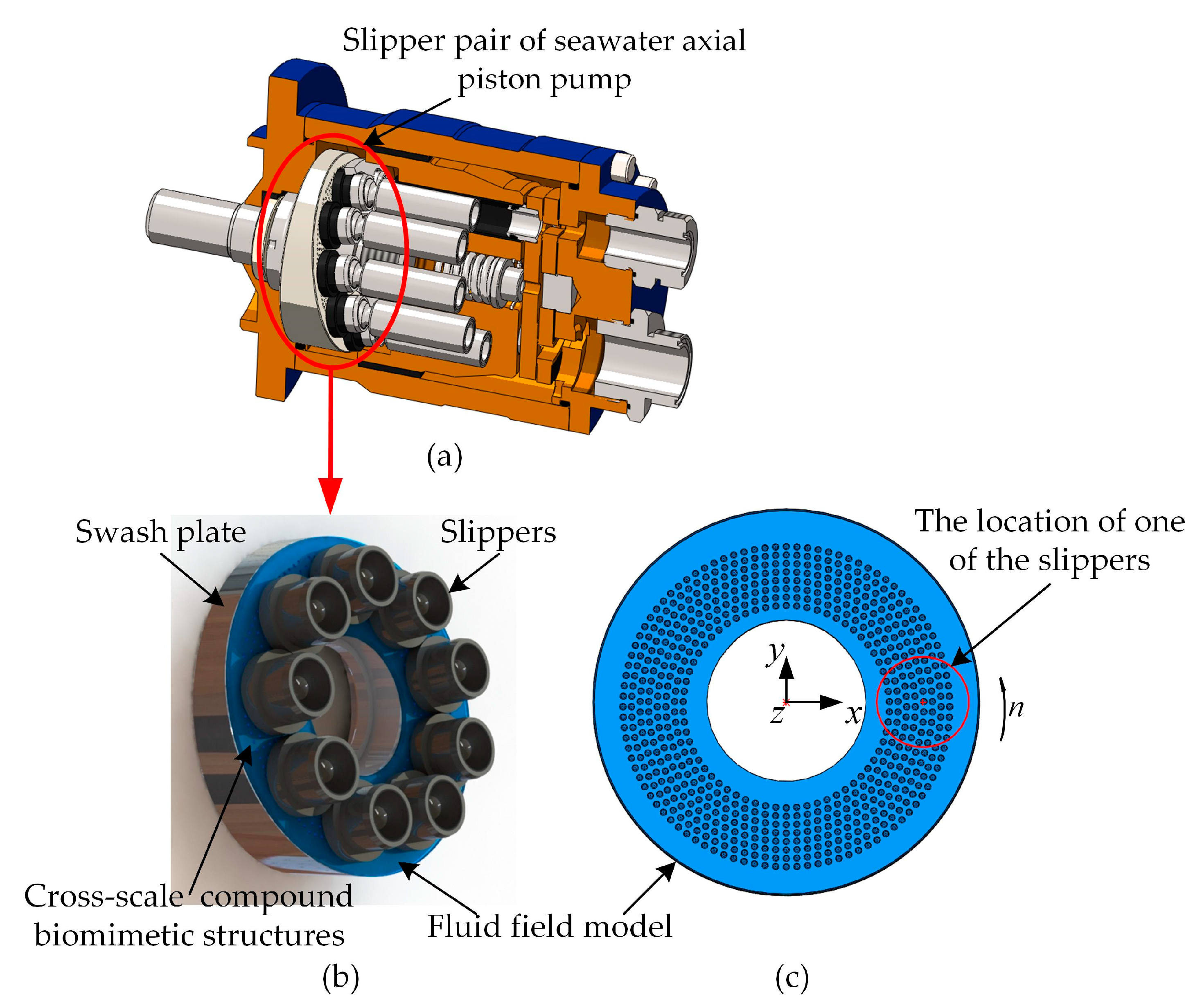
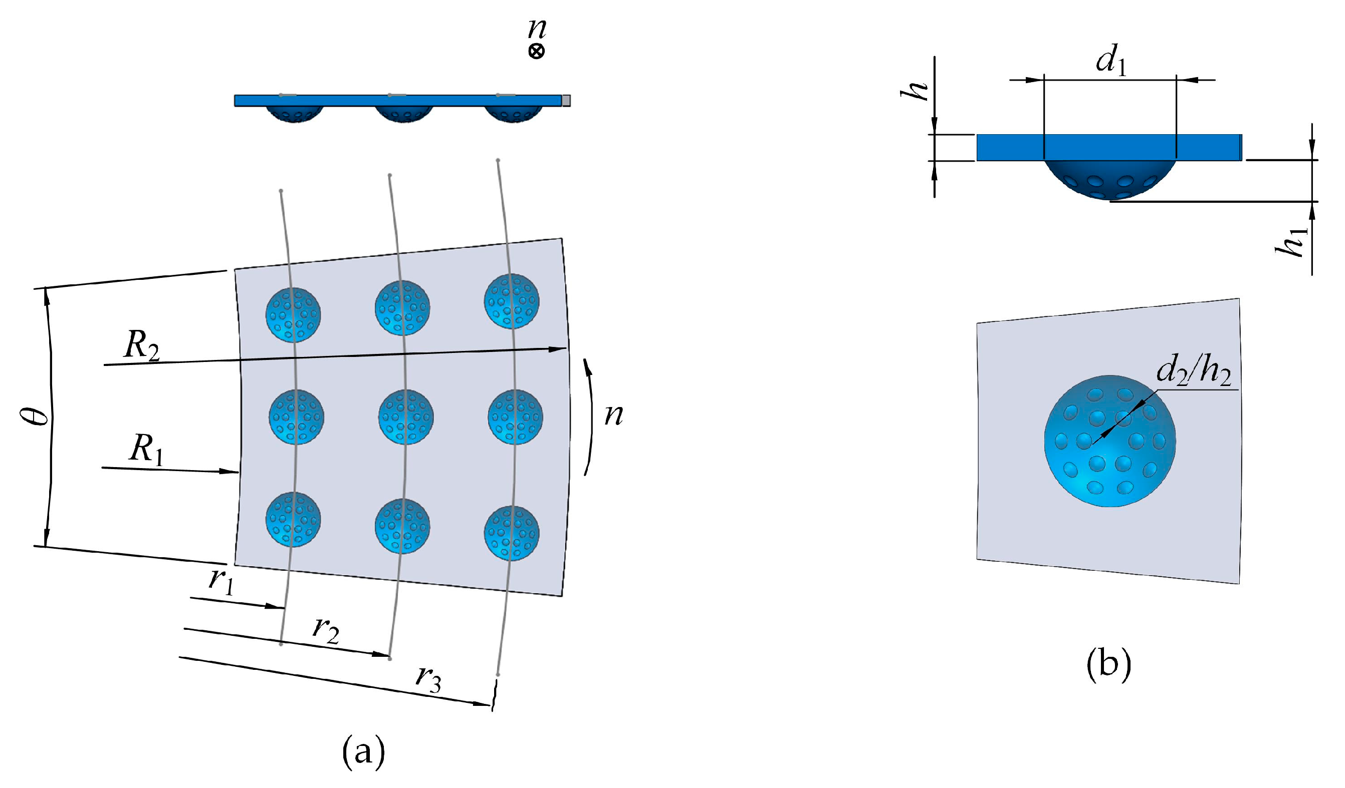
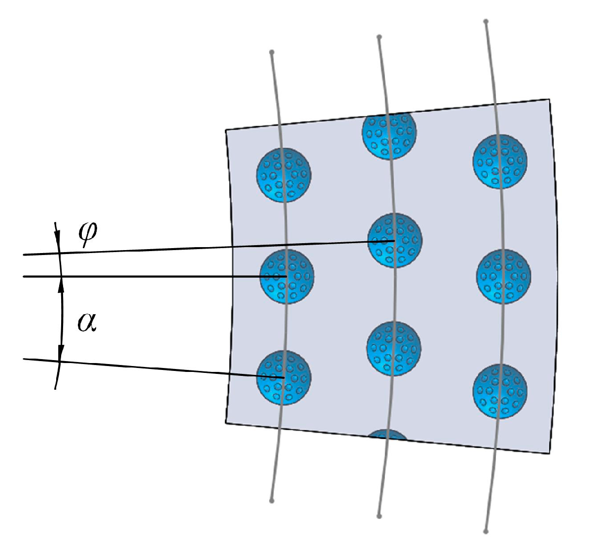
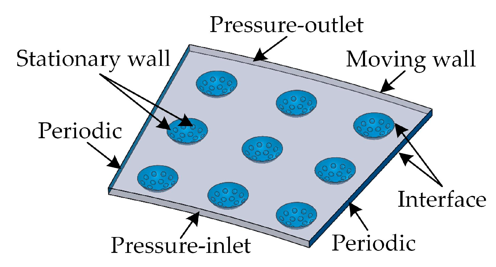
2.1. Model Description

For the slipper pair of seawater axial piston pumps (Figure 1a), the cross-scale compound biomimetic structures (spherical pits containing spherical convex hulls) were arranged on the surface of a swash plate, and the surface of the slippers remained smooth (Figure 1b). Assuming that the slipper pair is fully lubricated and setting the origin coordinate at the center of the front surface of the swash plate, the fluid field models of the water film and the cross-scale compound biomimetic structures were established. The small red circle on the right in Figure 1c is the location of one of the slippers.
In order to study the lubrication mechanism and influence law of the cross-scale compound biomimetic structures, a fan-shaped region covering about 3 × 3 spherical pits containing spherical convex hulls under the center of one slipper was selected as the computed fluid field, as shown in Figure 2. Each spherical pit is located in the center of an imaginary fan-shaped control unit, and the ratio between the total area of spherical pits and the total area of the fan shape is defined as the area rate S. Then:
S = 90 N d 1 2 ( R 2 2 R 1 2 ) θ
where R1 = 28.75 mm, R2 = 34.75 mm, θ = 10.8°; r1 = 29.75 mm, r2 = 31.75 mm, and r3 = 33.75 mm; N is the number of spherical pits containing spherical convex hulls; d1 is the diameter of the spherical pit (first order diameter); and n represents the direction in which the slippers rotate.
As shown in Figure 2b, h is the thickness of the water film, h1 is the depth of the spherical pit (first order depth), and the ratio of the depth of spherical pit h1 to the diameter of spherical pit d1 is defined as the first order depth-to-diameter ratio δ1. h2 is the depth of the spherical convex hull (second order depth), d2 is the diameter of the spherical convex hull (second order diameter), and the ratio of the depth of spherical convex hull h2 to the diameter of spherical convex hull d2 is defined as the second order depth-to-diameter ratio δ2. Then:
δ 1 = h 1 d 1
δ 2 = h 2 d 2
The diameter of a spherical pit or a spherical convex hull is controlled by the area rate, and the depth of a spherical pit or a spherical convex hull is controlled by the depth-to-diameter ratio.
As shown in Figure 3, α is the circumferential interval angle, which is the central angle formed by the centers of two adjacent spherical pits at the same distribution circle and the center of the swash plate; φ is the arrangement angle, which is the central angle formed the centers of two spherical pits at two adjacent distribution circles but not along the same radius and the center of the swash plate.
In order to study the influence of different shapes, sizes, and distributions of the cross-scale compound biomimetic structures on dynamic bearing characteristics under different working conditions, an orthogonal test scheme for numerical simulation was designed under the mixed levels of seven factors: rotate speed A, first order diameter B, first order depth-to-diameter ratio C, second order diameter D, second order depth-to-diameter ratio E, area rate F, and arrangement angle G. The details are shown in Table 1.

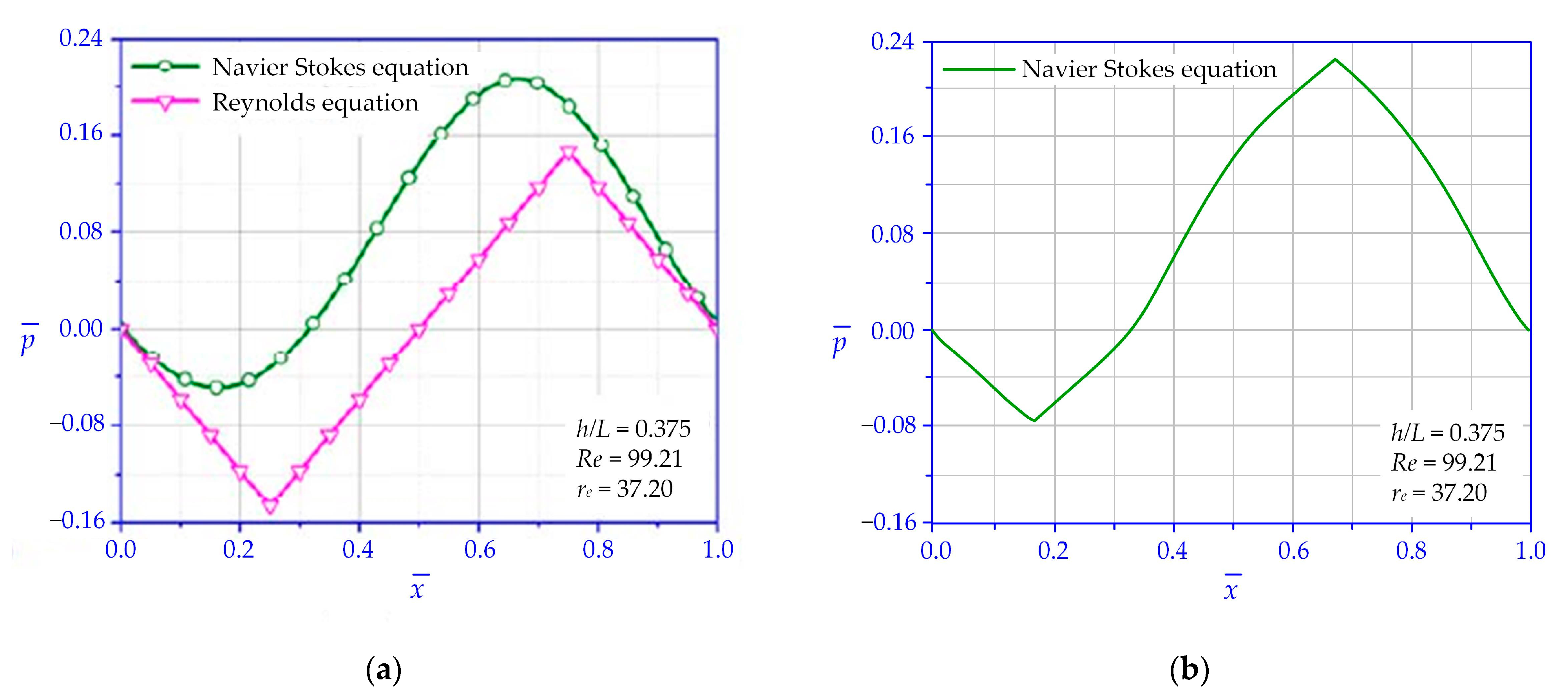
2.2. Governing Equation

The working medium in this study is seawater, which is a Newtonian fluid. The typical film thickness of hydrodynamic lubrication is 1~100 μm [31]. The lubrication film thickness of the slipper pair in a water pump can only reach one-third of that in an oil pump, which is controlled within 3.3~10 μm. The flow of the seawater in the narrow space between the surfaces of a slipper pair should follow the Navier–Stokes equation. The continuity equation and the Navier–Stokes equation [32] are employed to describe the problem studied:
u x + v y + w z = 0
{ ρ ( u u x + v u y + w u z ) = p x + η ( 2 u x 2 + 2 u y 2 + 2 u z 2 ) ρ ( u v x + v v y + w v z ) = p y + η ( 2 v x 2 + 2 v y 2 + 2 v z 2 ) ρ ( u w x + v w y + w w z ) = p z + η ( 2 w x 2 + 2 w y 2 + 2 w z 2 )
where u, v, and w are the velocity vectors in directions x, y, and z, respectively; ρ is the density of seawater (1.025 g/cm3); η is the dynamic viscosity of seawater (6.15 × 10⁻⁴ Pa·s); and p is the pressure of the lubricating film.

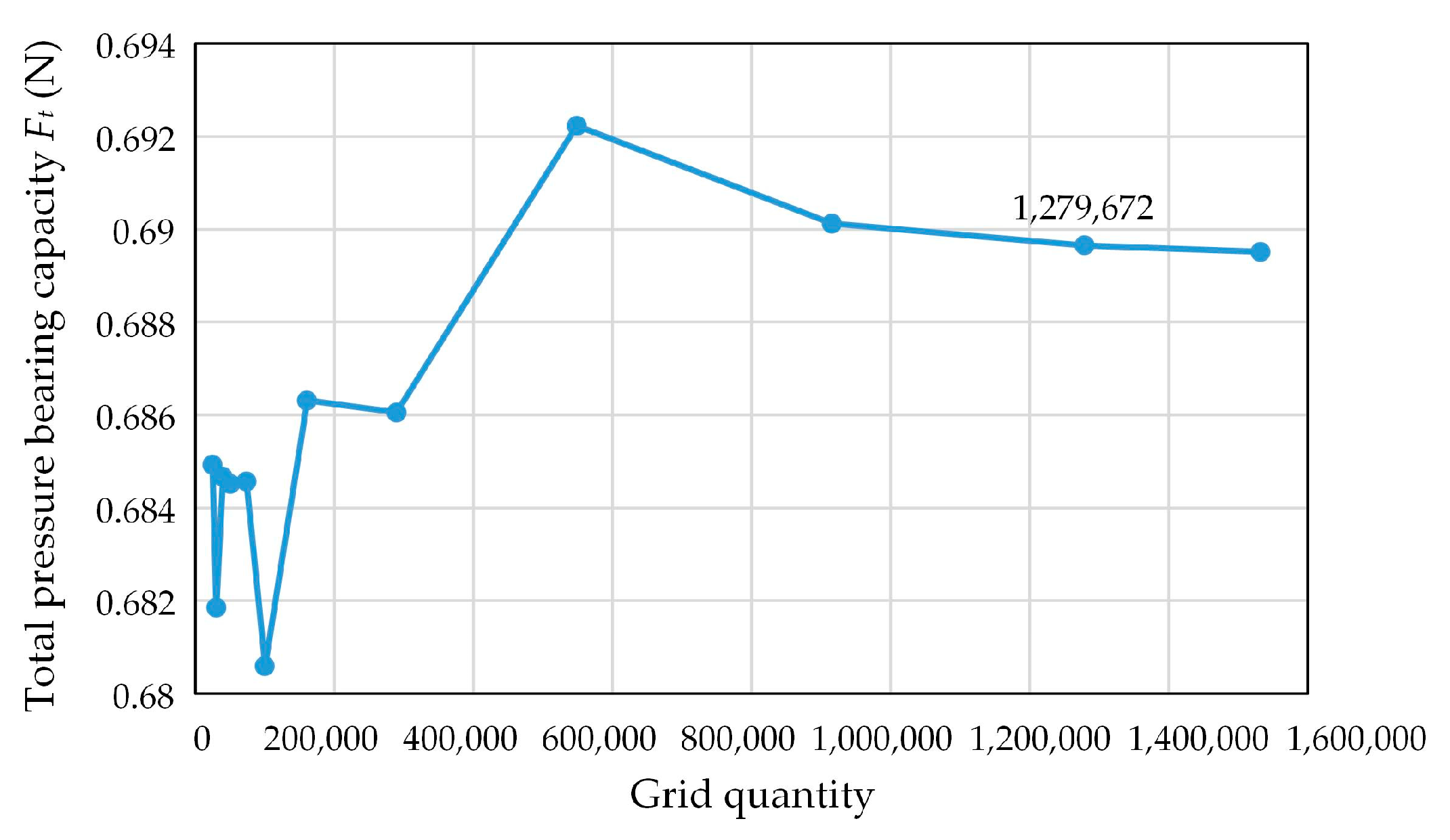
2.3. Simulation Strategy

The fan-shaped computed fluid field, which contains about 3 × 3 spherical pits containing spherical convex hulls, was modeled and imported into the CFD pre-processing software ICEM for grid division. The grid division method, grid quantity, and grid quality are vital to ensure the reliability of the numerical simulation results [33]. In order to explore the appropriate grid quantity for accurate calculation results, a grid independence verification was carried out, and the results are shown in Figure 4. When the grid quantity is less than 600,000, the calculation results are quite different. When the grid quantity is higher than 900,000, the error of the calculation results can be controlled within 0.1%. Therefore, the seawater film was meshed by hexahedral grids with the size of 0.02, the first-order spherical pits were meshed by tetrahedral grids with the size of 0.02, and the second-order spherical convex hulls were meshed by tetrahedral grids with the size of 0.008. The total number of units in the grid is about 2~19 million.
The model mesh was imported into the CFD software Fluent for numerical simulation. The flow of seawater film is similar to a plate differential pressure flow and can be regarded as being in a laminar state. Due to the low viscosity of seawater, the flow inertia force is greater than the viscous force [34], which makes it easy to generate local eddy currents in spherical pits and around the spherical convex hulls. Therefore, the standard k-ε model was used for calculation.
As shown in Figure 5, the inner and outer cylinder surfaces of the fan-shaped seawater film were set to pressure-inlet and pressure-outlet boundary conditions, respectively. The left and right surfaces were both set to periodic boundary rotation conditions. The upper surface of the seawater film (i.e., the lower surface of the slipper) was set to the moving wall boundary condition, which rotates around the coordinate axis perpendicular to the lower surface of the seawater film (i.e., the center line of the swash plate) at the corresponding speed listed in Table 1. The lower surface of the seawater film and the upper surfaces of the spherical pits were both set to interface boundary conditions to carry out the data transfer of two parts. The lower surfaces of the spherical pits and the spherical convex hulls were both set to stationary wall boundary conditions.
In order to verify the reliability of this solver, the hydrodynamic pressure lubrication problem of two-dimensional rectangular micro-pit texture solved by the Navier–Stokes equation in the reference literature [35] was firstly verified and calculated. The comparison of calculation results is shown in Figure 6. It can be seen that the shape of the pressure distribution curve is basically the same, and the differences of the extreme value of pressure are about 8%.

3. Results and Discussion

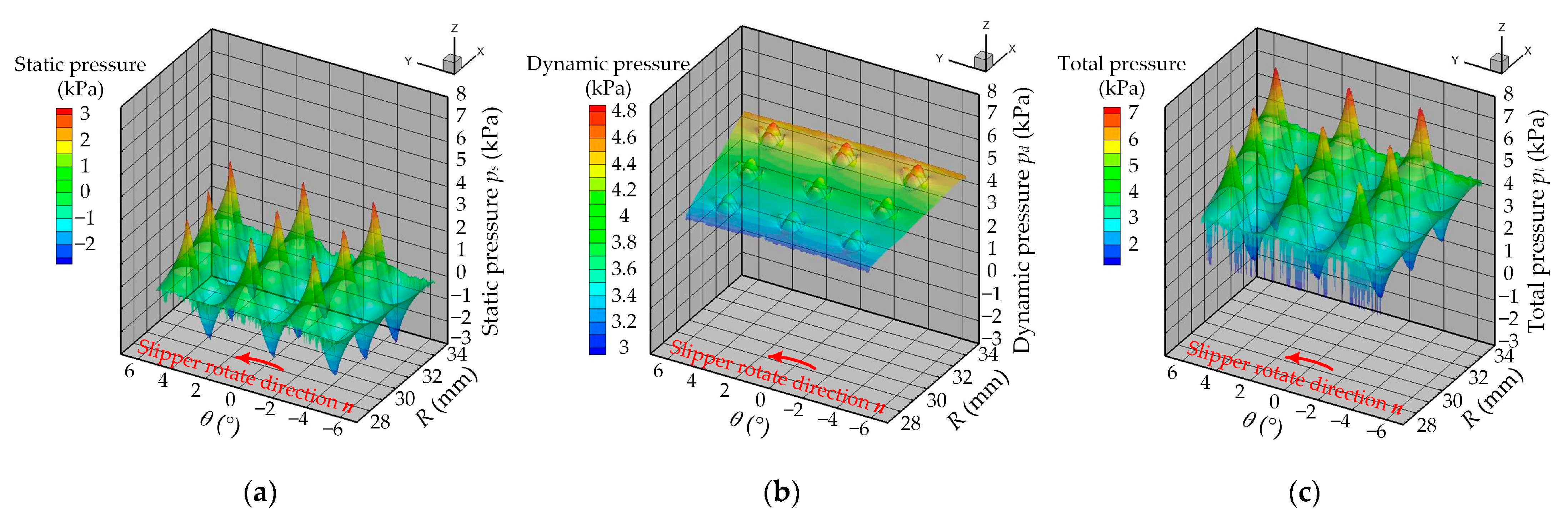
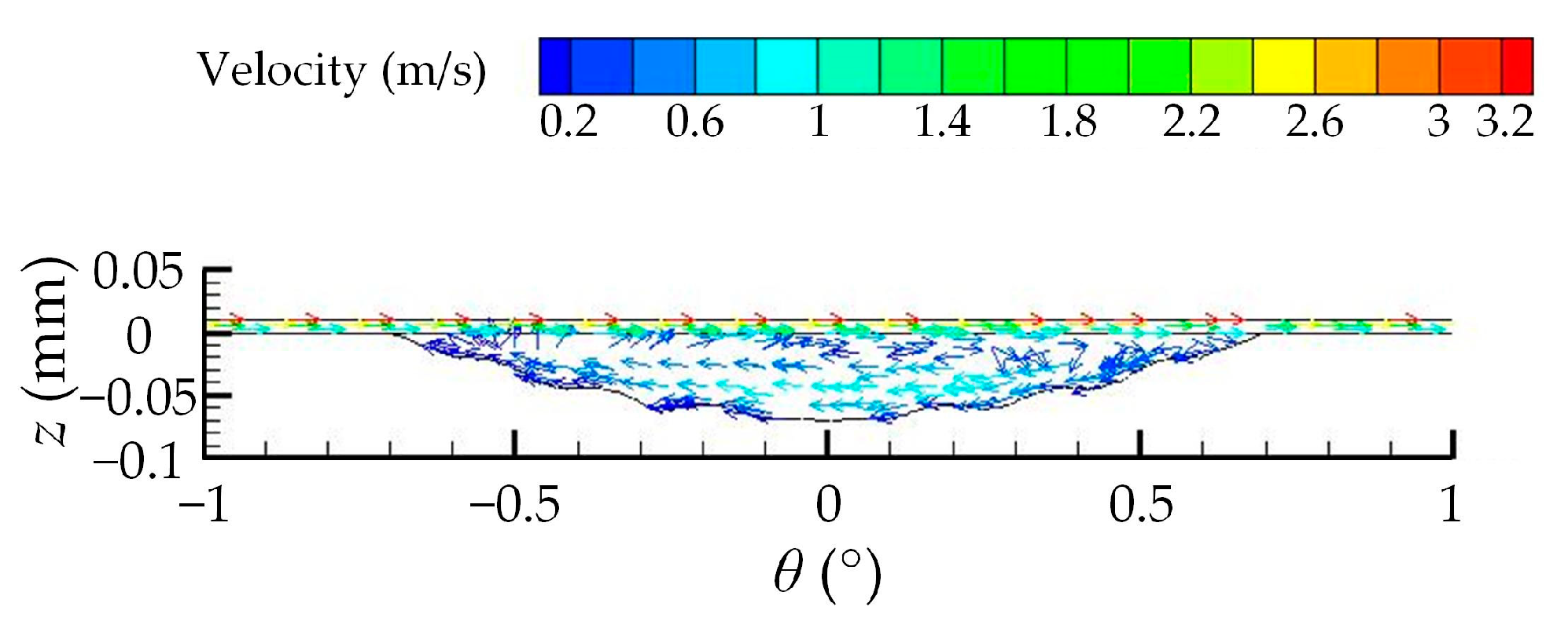
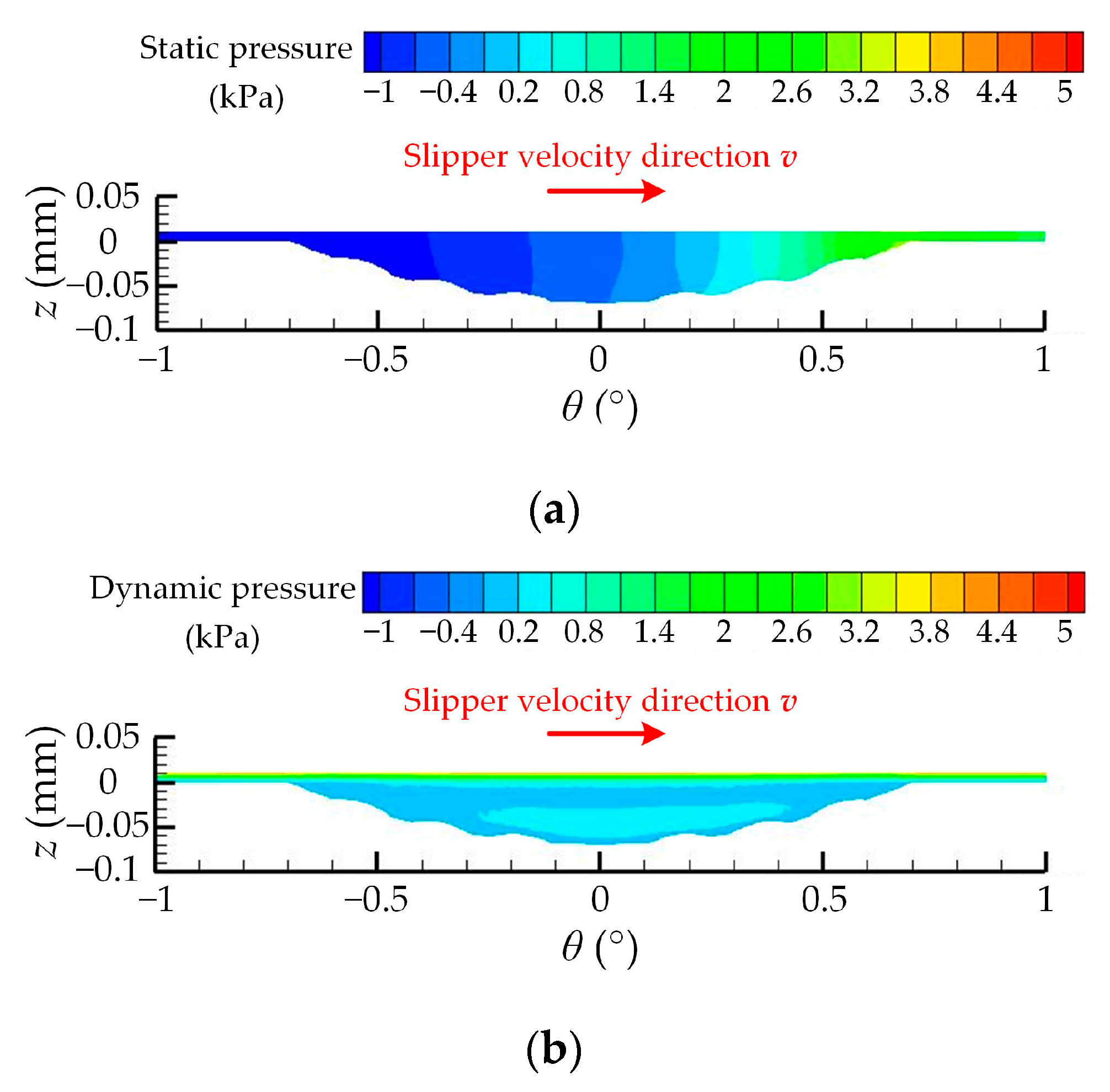
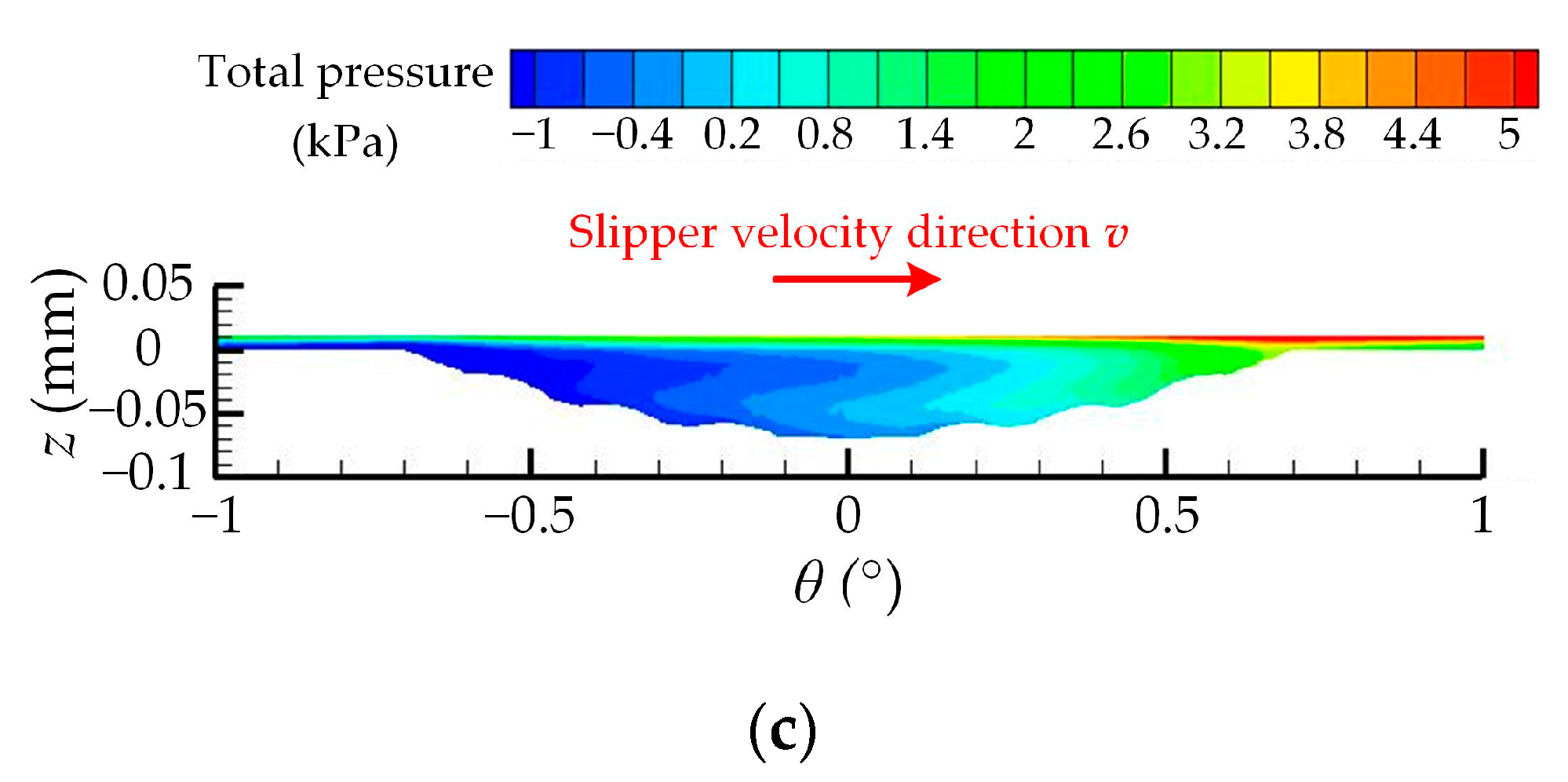
3.1. Analysis of Single Group Test Simulation Results

Taking the first calculation result in Table 1 as an example, there are 3 × 3 spherical pits containing spherical convex hulls uniformly distributed in the fan-shaped computed fluid field. Figure 7 and Figure 8 show the 3D pressure peak and 2D pressure contour of the upper surface of the seawater film, respectively.
In the calculation results using Fluent, static pressure is defined as the difference from the operating pressure (i.e., atmospheric pressure). Dynamic pressure is the pressure related to the velocity, and its value is ρv2/2. In an incompressible fluid, the total pressure is the sum of static pressure and dynamic pressure, which corresponds to the pressure p mentioned in the right term of the Navier–Stokes equation. As shown in Figure 7, n represents the rotation direction of the slipper, which rotates counterclockwise around the axis of the swash plate (z-axis). The static pressure ranges from −2.5 to 3 kPa, the dynamic pressure ranges from 3 to 5 kPa, and the total pressure ranges from 1.5 to 7 kPa, indicating that the total pressure mainly comes from the contribution of dynamic pressure.
It can be seen from Figure 7a and Figure 8a that the static pressure distribution of 3 × 3 spherical pits on the surface of the seawater film is positive in the front half and negative in the back half (along the speed direction of the slipper), and the static pressure distribution of the three pits on the same distribution circle is basically the same. With the increase in the radius of the distribution circle, the area and intensity of positive and negative pressure slightly increase.
Figure 7b and Figure 8b show that the dynamic pressure distribution in the spherical pit is low at the two sides and high in the center along the circular direction of the distribution circle and high at the two sides and low in the center along the radial direction of the distribution circle. The fluid flow is the relative sliding between many extremely thin fluid layers. The viscosity of the fluid generates shear stress between layers sliding over each other, which slows down the layers with faster flows and accelerates the layers with slower flows; the movement is transmitted layer by layer [31]. Figure 9 shows the velocity vector of the central spherical pit longitudinally sliced by the distribution cylinder of r2 = 31.75 mm. The maximum velocity appears on the upper surface of the seawater film which is in contact with the slipper sole. When the slipper drives the upper fluid layer to move above the spherical pit, the depth increases and the velocity needs to be transmitted down to more fluid layers, so the velocity loss of the upper surface of the seawater film here is larger than in places without pits. However, the seawater in the upper part of the pit first moves following the seawater at the lower surface of the seawater film. After hitting the front half of the pit wall, it turns downward to flow back along the bottom of the pit. After hitting the back half of the pit wall, it turns upward to move in the same direction as the seawater at the lower surface of the seawater film again; that is, a vortex ring is formed in the spherical pit. This flow vortex ring can also be found in the simulation study by Wang et al. [36]. The upper part of the vortex ring transmits velocity to the middle layer of the seawater film together with the upper layer. Therefore, the velocity loss of the upper surface of the seawater film at the center of the spherical pit is compensated, and the dynamic pressure is basically equal to areas without pits. The vortex ring changes direction at the front and back edges of the spherical pit, which increases the velocity loss. That is why the dynamic pressure decreases at the two sides of the pit along the circular direction of the distribution circle. Along the radial direction of the distribution circle, the dynamic pressure is higher at the two sides of the pit. Because the depth decreases gradually from the center to the edge, the velocity compensation effect of the vortex ring is gradually enhanced. As the radius of the distribution circle increases, the linear velocity increases obviously, and the dynamic pressure increases obviously as well.
Figure 7c and Figure 8c show that the total pressure distribution is similar to the static pressure, while the high-pressure area increases and the low-pressure area decreases with the increase in the distribution circle’s radius. The total pressure of the upper surface of the seawater film is all positive, indicating that the spherical pits containing spherical convex hulls could produce a hydrodynamic pressure effect. The results are consistent with the previous study results by Tang et al. [37].
Figure 10 shows the 2D pressure contour of the central spherical pit longitudinally sliced by the distribution cylinder of r2 = 31.75 mm. As shown in Figure 10a, the maximum positive static pressure appears at the front edge of the spherical pit, the minimum negative static pressure appears at the back edge, and there is a rainbow-shaped gradient distribution in the middle.
Dynamic pressure is the pressure change caused by the velocity change, which is proportional to the square of the velocity. As shown in Figure 10b, the dynamic pressure is positive. The maximum dynamic pressure appears on the upper surface of the seawater film and decreases along the thickness direction. The dynamic pressure value at the lower part of the vortex ring rebounds slightly.
The total pressure is the synthesis of static pressure and dynamic pressure, which is the macroscopic manifestation of the hydrodynamic pressure effect of the spherical pits containing spherical convex hulls. When the upper surface of the seawater film moves to the right at a certain speed, a convergence gap is formed along the direction of the movement, the seawater flows from the large section to the small section, and the flow rate per unit length caused by velocity flow gradually decreases. To keep the flow continuous, the pressure distribution shown in Figure 7c is generated. The pressure flow caused by this pressure distribution will reduce the inflow at the large section and increase the outflow at the small section to keep the flow equal across the sections. As shown in Figure 10c, the total pressure is almost all positive. Similar to static pressure distribution, the maximum total pressure appears at the front edge and the minimum total pressure appears at the back edge. However, the high-pressure contour lines of the rainbow-shaped gradient distribution significantly bend to the left near the bottom of the spherical pit. This is because the spherical convex hulls produce second-order hydrodynamic pressure effects and enlarge the range of the high-pressure area.

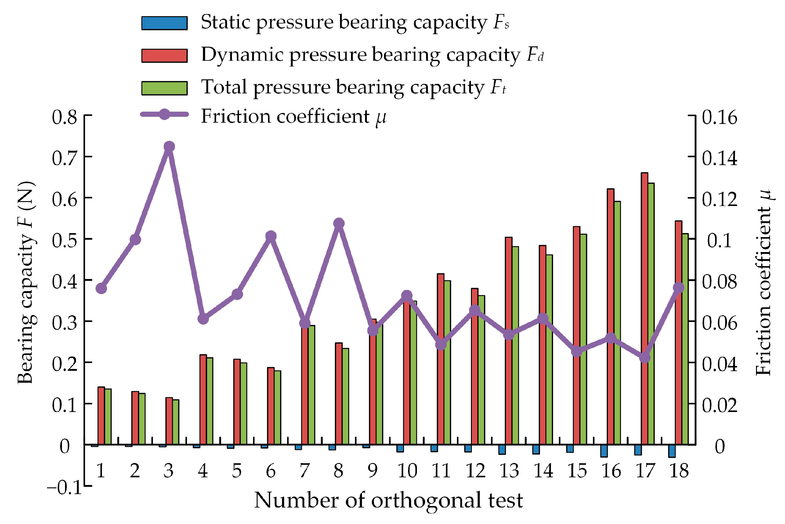
3.2. Range Analysis of Multi-Index Orthogonal Test Results

By integrating the static pressure distribution, dynamic pressure distribution, and total pressure distribution of the upper surface of the seawater film on the fan-shaped domain, the static pressure-bearing capacity FS, dynamic pressure-bearing capacity Fd, and total pressure-bearing capacity Ft of the calculation domain could be obtained. Meanwhile, the shear stress of the upper surface of the seawater film was extracted, and the friction coefficient μ was calculated. The total pressure-bearing capacity and friction coefficient were added to the last two columns of Table 1. The histogram of the bearing capacity and the line chart of the friction coefficient for 18 groups of tests in the orthogonal simulation scheme are shown in Figure 11.
As shown in Figure 11, the static pressure-bearing capacity is negative and the value is low. The dynamic pressure-bearing capacity and total pressure-bearing capacity are both positive, and the heights of their respective columns are much higher than that of the static pressure-bearing capacity, indicating that the hydrodynamic pressure effect can produce load bearing and lubrication effects and that the total pressure-bearing capacity mainly comes from the contribution of dynamic pressure-bearing capacity. The line chart shows that the friction coefficient is inversely proportional to the bearing capacity. The bearing capacity increases and the friction coefficient decreases obviously with the increase in the rotation speed.
Table 2 shows the range analysis of L18(6 × 36) multi-index orthogonal test results. The sum Ki and average ki of the two test indices of total pressure-bearing capacity and friction coefficient corresponding to each level of each factor were calculated, and the range R and the adjusted range R’ of each factor were calculated. According to the adjusted range R’, the order of the factors under the total pressure-bearing capacity is A > C > F > E > G > D > B; the order of the factors under the friction coefficient is C > A > B > F > G > E > D. According to the average ki of each level of each factor, the optimal combination is determined as A6B1C1D3E3F2G2 under the total pressure-bearing capacity and A5B1C1D1E3F1G2 under the friction coefficient.
The comprehensive balance method is adopted to determine the optimal combination that makes each index as good as possible [38]. For factor A, the rank under the total pressure-bearing capacity is first and the optimal level is A6, and the rank under the friction coefficient is second and the optimal level is A5. If A6 is taken, the total pressure-bearing capacity increases by 19.6% compared with A5, while the friction coefficient only increases by 6.6%, so A6 is preferable to A5 after comprehensive comparison. Similarly analyzed, D is taken as D3 and F is taken as F2. The optimal combination is determined as A6B1C1D3E3F2G2 through comprehensive balancing.
The structural combination of B1C1D3E3 would make the spherical convex hulls higher than the spherical pit plane, so the optimal combination was modified to A6B1C1D3E2F2G2. The above strategy was used to simulate the optimal combination. The results show that the total pressure-bearing capacity can reach 0.6897 N, which is higher than the maximum of 0.6349 N across the 18 tests. The friction coefficient is reduced to 0.0401, which is lower than the minimum of 0.0423 across the 18 tests.

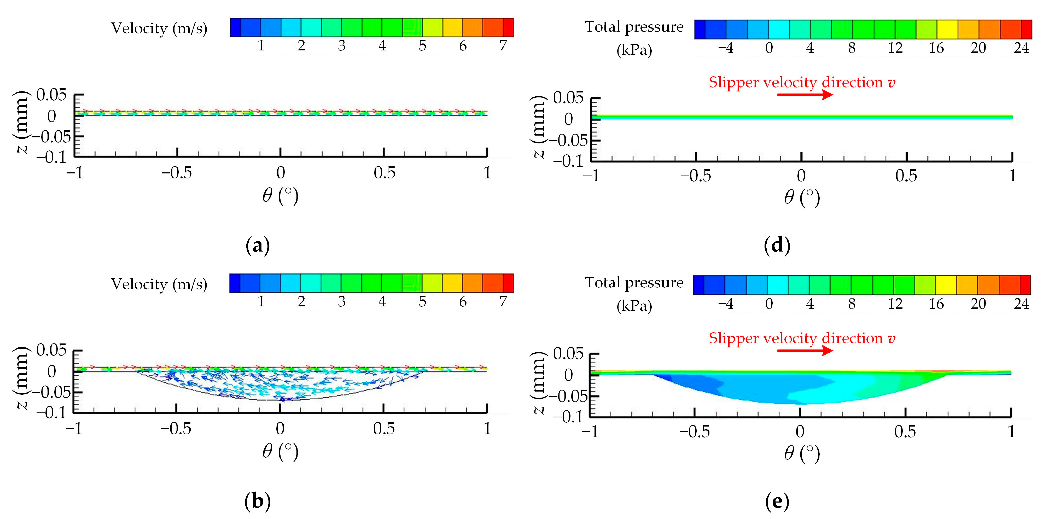
3.3. Comparative Analysis of Bearing Capacity and Lubrication Characteristics of Different Surfaces

Based on the structure of the optimal combination A6B1C1D3E2F2G2 (second-order non-smooth structure), the spherical convex hulls were removed, and the spherical pit surface (first-order non-smooth structure) with the same size was modeled and simulated. The smooth surface was also simulated as a control. Figure 12 shows the velocity vector and the 2D total pressure contour of the profile of r2 = 31.75 mm of different surfaces. Figure 13 shows the 2D total pressure contour of the upper surface of the seawater film of different surfaces.
As analyzed in Section 3.1, the maximum velocity of a smooth surface only decreases layer by layer from the upper surface of the seawater film, and no hydrodynamic pressure effect is generated. The total pressure on the upper surface of the seawater film is distributed in a circular zonal pattern, gradually increasing from inside to outside, and only reaches 10~20 kPa.
The non-smooth surface produces a hydrodynamic pressure effect at the pit, and the total pressure on the surface of the seawater film can reach 30 kPa. Comparing Figure 12b,c,e,f, the second-order non-smooth structure generates not only a large vortex ring in the first order spherical pit, but also some small vortex rings near the second order spherical convex hulls. Therefore, the superimposed hydrodynamic pressure effect can be generated near the second order spherical convex hulls to expand the range of the high-pressure zone, thus producing a larger bearing capacity and a lower friction coefficient and obtaining better lubrication performance.
Table 3 shows the total pressure-bearing capacity and friction coefficient of different surfaces. It can be seen that the total pressure-bearing capacity of the second-order non-smooth structure increased by 11.0% and 8.9% over that of the smooth surface and the first-order non-smooth structure, respectively, and the friction coefficient decreased by 9.5% and 5.4% over that of the smooth surface and the first-order non-smooth structure, respectively.

4. Conclusions

Aiming to address problems of the poor lubricity and the serious friction and wear of friction pairs of seawater axial piston pumps, a hydrodynamic lubrication model of a slipper pair with a surface featuring spherical pits containing spherical convex hulls was built. Through the simulation analysis of the bearing lubrication mechanism and friction characteristics of the cross-scale, second-order compound microstructure from the microflow perspective, the following conclusions are drawn:
(1) The cross-scale, second-order compound microstructure could produce a hydrodynamic pressure effect to improve the bearing capacity of the lubrication film of a slipper pair. Along the velocity direction, seawater flows through the front part of the spherical pits (convergence wedge) to produce high pressure and through the back part of the spherical pits (divergence wedge) to produce low pressure, both of which have positive values. When seawater flows to spherical convex hulls, a hydrodynamic pressure effect is also generated to further expand the high-pressure zone.
(2) The total pressure is the synthesis of the static pressure and dynamic pressure, which is the macroscopic manifestation of the hydrodynamic pressure effect produced by the cross-scale, second-order compound microstructure. The total pressure-bearing capacity mainly comes from the contribution of the dynamic pressure to the bearing capacity that is proportional to the square of the velocity. Moreover, the friction coefficient is inversely proportional to the total pressure-bearing capacity. Thus, increasing the rotating speed can improve the bearing capacity of the lubrication film of the slipper pair, reduce the friction coefficient, and improve the lubrication performance.
(3) A hybrid orthogonal test scheme is used to find the order and optimal combination of factors under multiple indices. The order of the factors under the total pressure-bearing capacity is A (rotate speed) > C (first order depth-to-diameter ratio) > F (area rate) > E (second order depth-to-diameter ratio) > G (arrangement angle) > D (second order diameter) > B (first order diameter). The order under the friction coefficient is C > A > B > F > G > E > D. The optimal combination is A6B1C1D3E3F2G2 under the total pressure-bearing capacity and A5B1C1D1E3F1G2 under the friction coefficient. The final optimal combination is modified to A6B1C1D3E2F2G2 through comprehensive balancing and analysis.
(4) The superimposed hydrodynamic pressure effect makes the cross-scale second-order compound microstructure obtain better bearing lubrication capacity and friction performance. Compared to the smooth surface and the first-order non-smooth microstructure, the total pressure-bearing capacity increased by 11.0% and 8.9%, respectively, and the friction coefficient decreased by 9.5% and 5.4%, respectively.
This study analyzed the bearing lubrication mechanism and friction characteristics of the cross-scale, second-order compound microstructure from the microflow perspective via the CFD method and optimized the working parameter and geometric parameters using a hybrid orthogonal test scheme. This study provides an effective solution and optimization reference for solving problems of the poor lubricity and the serious friction and wear of slipper pairs of seawater axial piston pumps. This solution can be extended to the design of friction pairs of other hydraulic components. Corresponding friction and wear tests need to be carried out in the future work to verify the reliability of the simulation analysis and to investigate the wear mechanism.

Author Contributions

Conceptualization, Y.L. and D.G.; methodology, Y.L.; software, C.W. and Z.Z. (Zongyi Zhang); validation, Z.Z. (Zhepeng Zhang) and W.W.; formal analysis, H.X. and T.G.; investigation, Y.L. and C.W.; resources, Y.L.; data curation, Z.Z. (Zongyi Zhang); writing—original draft preparation, Y.L., C.W. and Z.Z. (Zongyi Zhang); writing—review and editing, D.G., Z.Z. (Zhepeng Zhang), W.W., H.X. and T.G.; supervision, D.G.; project administration, D.G.; funding acquisition, Y.L. and D.G. All authors have read and agreed to the published version of the manuscript.

Funding

This research was supported by the National Natural Science Foundation of China (Grant No. 52005428), the Hebei Natural Science Foundation (Grant No. E2020203107 and Grant No. E2021203099), and the Open Fund Project of Shaanxi Provincial Key Laboratory of Hydraulic Technology (No. YYJS2022KF04).

Institutional Review Board Statement

Not applicable.

Informed Consent Statement

Not applicable.

Data Availability Statement

All data generated or analyzed during this study are included in this article.

Conflicts of Interest

The authors declare no conflict of interest.

References

  1. Ren, L.Q.; Yang, Z.J.; Han, Z.W. Non-smooth wearable surface of living creatures and their bionic application. Trans. Chin. Soc. Agric. Mach. 2005, 36, 144–147. [Google Scholar]
  2. Li, X.F.; Guo, Z.W.; Huang, Q.R.; Yuan, C.Q. Application of bionic tribology in water-lubricated bearing: A review. J. Bionic Eng. 2022, 19, 902–934. [Google Scholar] [CrossRef]
  3. Tian, G.Z.; Zhang, Y.S.; Feng, X.M.; Hu, Y.S. Focus on bioinspired textured surfaces toward fluid drag reduction: Recent progresses and challenges. Adv. Eng. Mater. 2022, 24, 2100696. [Google Scholar] [CrossRef]
  4. Gachot, C.; Rosenkranz, A.; Hsu, S.M.; Costa, H.L. A critical assessment of surface texturing for friction and wear improvement. Wear 2017, 372–373, 21–41. [Google Scholar] [CrossRef]
  5. Zhang, J.; Chen, Y.; Xu, B.; Chao, Q.; Zhu, Y.; Huang, X.C. Effect of surface texture on wear reduction of the tilting cylinder and the valve plate for a high-speed electro-hydrostatic actuator pump. Wear 2018, 414–415, 68–78. [Google Scholar] [CrossRef]
  6. Wang, Z.Q.; Fu, Q.; Wood, R.J.K.; Wu, J.; Wang, S.C. Influence of bionic non-smooth surface texture on tribological characteristics of carbon-fiber-reinforced polyetheretherketone under seawater lubrication. Tribol. Int. 2020, 144, 106100. [Google Scholar] [CrossRef]
  7. Watanabe, S.; Kodama, E.; Sakakibara, K.; Sasaki, S.; Tsujii, Y. Effect of surface texturing on the durability of concentrated polymer brushes. Tribol. Int. 2021, 155, 106668. [Google Scholar] [CrossRef]
  8. Song, F.; Yang, X.F.; Dong, W.L.; Zhu, Y.Q.; Wang, Z.Y.; Wu, M. Research and prospect of textured sliding bearing. Int. J. Adv. Manuf. Technol. 2022, 121, 1–25. [Google Scholar] [CrossRef]
  9. Hou, Q.M.; Yang, X.F.; Cheng, J.; Wang, S.R.; Duan, D.R.; Xiao, J.P.; Li, W.Y. Optimization of performance parameters and mechanism of bionic texture on friction surface. Coatings 2020, 10, 171. [Google Scholar] [CrossRef]
  10. Wei, Y.; Resendiz, J.; Tomkowski, R.; Liu, X. An experimental study of micro-dimpled texture in friction control under dry and lubricated conditions. Micromachines 2022, 13, 70. [Google Scholar] [CrossRef]
  11. Liang, Y.N.; Gao, D.R.; Chen, B.; Zhao, J.H. Friction and wear study on friction pairs with a biomimetic non-smooth surface of 316L relative to CF/PEEK under a seawater lubricated condition. Chin. J. Mech. Eng. 2019, 32, 66. [Google Scholar] [CrossRef] [Green Version]
  12. Liang, Y.N.; Gao, D.R.; Zhao, J.H. Tribological properties of friction pair between 316L stainless steel and CF/PEEK with nonsmooth surface under seawater lubrication. Tribol. Trans. 2020, 63, 658–671. [Google Scholar] [CrossRef]
  13. Liang, Y.N.; Gao, J.X.; Gao, D.R.; Sun, Y.N.; Zhang, Z.Y.; Zhao, J.H. Effect of micro-textured surfaces and sliding speed on the lubrication mechanism and friction-wear characteristics of CF/PEEK rubbing against 316L stainless steel under seawater lubrication. Appl. Sci. 2021, 11, 9915. [Google Scholar] [CrossRef]
  14. Uddin, M.S.; Liu, Y.W. Design and optimization of a new geometric texture shape for the enhancement of hydrodynamic lubrication performance of parallel slider surfaces. Biosurface Biotribology 2016, 2, 59–69. [Google Scholar] [CrossRef]
  15. Ni, S.L.; Wu, H.C.; Zhao, L.M.; Yang, L. Effect of surface micro-pit on oil film performance of slipper pair in axial piston pump under high pressure. Lubr. Eng. 2018, 43, 30–34, 42. [Google Scholar]
  16. Ni, S.L.; Wu, H.C.; Zhao, L.M.; Yang, L. Study on the effect of material matching to the performance of dry friction of the slipper pair in axial piston pump under high pressure. Mach. Des. Manuf. 2019, 3, 12–15. [Google Scholar]
  17. Sugihara, T.; Enomoto, T. Performance of cutting tools with dimple textured surfaces: A comparative study of different texture patterns. Precis. Eng. 2017, 49, 52–60. [Google Scholar] [CrossRef]
  18. Lin, X.K.; Kinoshita, S.; Sugihara, T.; Enomoto, T. Exploring the role of the interface adhesion phenomena focusing on surface expansion distribution. Tribol. Int. 2023, 179, 108160. [Google Scholar] [CrossRef]
  19. Liu, S.C.; Sai, Q.Y.; Wang, S.W.; Williams, J. Effects of laser surface texturing and lubrication on the vibrational and tribological performance of sliding contact. Lubricants 2022, 10, 10. [Google Scholar] [CrossRef]
  20. Naduvinamani, N.; Angadi, A. Static and dynamic characteristics of rough porous Rayleigh step bearing lubricated with couple stress fluid. Lubricants 2022, 10, 257. [Google Scholar] [CrossRef]
  21. Liu, B. Studies on the Morphological Dimensions of the Riblet Surface of Fast-Swimming Sharks. Master Degree Thesis, Qingdao University of Science & Technology, Qingdao, China, 2008. [Google Scholar]
  22. Lloyd, C.J.; Peakall, J.; Burns, A.D.; Keevil, G.M.; Dorrell, R.M.; Wignall, P.B.; Fletcher, T.M. Hydrodynamic efficiency in sharks: The combined role of riblets and denticles. Bioinspiration Biomim. 2021, 16, 046008. [Google Scholar] [CrossRef]
  23. Barthlott, W.; Neinhuis, C. Purity of the sacred lotus, or escape from contamination in biological surfaces. Planta 1997, 202, 1–8. [Google Scholar] [CrossRef]
  24. Lu, Y. Superior lubrication properties of biomimetic surfaces with hierarchical structure. Tribol. Int. 2018, 119, 131–142. [Google Scholar] [CrossRef]
  25. Sun, J.R.; Cheng, H.; Cong, Q.; Li, J.Q.; Chen, B.C.; Ren, L.Q. Bionic study on the dung beetle (Copris ochus Motschulsky) for reduction of soil adhesion. Acta Biophys. Sin. 2001, 17, 785–793. [Google Scholar]
  26. Cheng, H.; Sun, J.R.; Li, J.Q.; Ren, L.Q. Structure of the integumentary surface of the dung beetle Copris ochus Motschulsky and its relation to non-adherence of substrate particles. Acta Entomol. Sin. 2002, 45, 175–181. [Google Scholar]
  27. Liu, Y.S.; Wu, D.F.; Li, D.L.; Deng, Y.P. Applications and research progress of hydraulic technology in deep sea. J. Mech. Eng. 2018, 54, 14–23. [Google Scholar] [CrossRef]
  28. Yan, X.P.; Bai, X.Q.; Yuan, C.Q. Discussion on connotation and research scopes of ocean tribology and its research progress. J. Mech. Eng. 2013, 49, 95–103. [Google Scholar] [CrossRef]
  29. Wang, W.; Wen, H.X.; Chen, W. Research status on tribological behaviors of materials under seawater environment. Mater. Rep. 2017, 31, 51–58. [Google Scholar]
  30. Nie, S.L.; Yin, F.L. Progress and prospect of water hydraulic piston pump. Chin. Hydraul. Pneum. 2015, 1, 1–7. [Google Scholar]
  31. Wen, S.Z.; Huang, P.; Tian, Y.; Ma, L.R. Principles of Tribology, 5th ed.; Tsinghua University Press: Beijing, China, 2018; p. 3. [Google Scholar]
  32. Chen, Z.R.; Wang, H.J.; Liu, Q.Z.; Cai, W.H. Engineering Fluid Mechanics, 3rd ed.; Higher Education Press: Beijing, China, 2013. [Google Scholar]
  33. Feng, J.A.; Tang, X.Q.; Wang, W.B.; Ying, R.; Zhang, T. Reliability verification method of numerical simulation based on grid independence and time independence. J. Shihezi Univ. Nat. Sci. 2017, 35, 52–56. [Google Scholar]
  34. Lachner, H. Hydrostatic lagerungen in axialkolbenmachine. Hydraul. Pneum. 1974, 18, 605–611. [Google Scholar]
  35. Han, J. Study on the Lubrication and Friction Properties of Macroscale and Microscale Surface Texture. Doctor Degree Thesis, China University of Mining & Technology, Xuzhou, China, 2013. [Google Scholar]
  36. Wang, Y.J.; Jacobs, G.; König, F.; Zhang, S.; Goeldel, V.S. Investigation of microflow effects in textures on hydrodynamic performance of journal bearings using CFD simulations. Lubricants 2023, 11, 20. [Google Scholar] [CrossRef]
  37. Tang, W.; Zhou, Y.K.; Zhu, H.; Yang, H.F. The effect of surface texturing on reducing the friction and wear of steel under lubricated sliding contact. Appl. Surf. Sci. 2013, 273, 199–204. [Google Scholar] [CrossRef]
  38. He, W.; Xue, W.D.; Tang, B. Optimize Experimental Design Method and Data Analysis; Chemical Industry Press: Beijing, China, 2012. [Google Scholar]
Figure 1. Slipper pair with biomimetic non-smooth surface and the fluid field model. (a) The seawater axial piston pump; (b) the slipper pair with cross-scale compound biomimetic structures (spherical pits containing spherical convex hulls); and (c) the fluid field models of water film and cross-scale compound biomimetic structures.
Lubricants 11 00077 g001
Figure 2. The fan-shaped computed fluid field. (a) The arrangement of spherical pits containing spherical convex hulls; (b) the structure of spherical pits containing spherical convex hulls.
Lubricants 11 00077 g002
Figure 3. The arrangement angle of spherical pits containing spherical convex hulls.
Lubricants 11 00077 g003
Figure 4. Grid independence verification.
Lubricants 11 00077 g004
Figure 5. Boundary condition setting.
Lubricants 11 00077 g005
Figure 6. Validation of the current solver. (a) Pressure distribution in Ref. [35]; (b) pressure distribution with the current solver.
Lubricants 11 00077 g006
Figure 7. The 3D pressure peak of the upper surface of the seawater film. (a) The 3D static pressure peak; (b) the 3D dynamic pressure peak; (c) the 3D total pressure peak.
Lubricants 11 00077 g007
Figure 8. The 2D pressure contour of the upper surface of the seawater film. (a) The 2D static pressure contour; (b) the 2D dynamic pressure contour; (c) the 2D total pressure contour.
Lubricants 11 00077 g008
Figure 9. Velocity vector of the central spherical pit longitudinally sliced by the distribution cylinder of r2 = 31.75 mm.
Lubricants 11 00077 g009
Figure 10. The 2D pressure contour of the central spherical pit longitudinally sliced by the distribution cylinder of r2 = 31.75 mm. (a) The 2D static pressure contour; (b) the 2D dynamic pressure contour; (c) the 2D total pressure contour.
Lubricants 11 00077 g010aLubricants 11 00077 g010b
Figure 11. Histogram of bearing capacity and line chart of friction coefficient of 18 groups of tests in the orthogonal simulation scheme.
Lubricants 11 00077 g011
Figure 12. Velocity vector and 2D total pressure contour of the profile of r2 = 31.75 mm of different surfaces. (a) Velocity vector of a smooth surface; (b) velocity vector of a spherical pit; (c) velocity vector of a spherical pit containing spherical convex hulls; (d) 2D total pressure contour of a smooth surface; (e) 2D total pressure contour of a spherical pit; and (f) 2D total pressure contour of a spherical pit containing spherical convex hulls.
Lubricants 11 00077 g012aLubricants 11 00077 g012b
Figure 13. The 2D total pressure contour of the upper surface of the seawater film of different surfaces: (a) smooth surface; (b) spherical pit; (c) spherical pit containing spherical convex hulls.
Lubricants 11 00077 g013
Table 1. L18(6 × 36) orthogonal test scheme for numerical simulation.
NumberExperimental FactorTotal Pressure-Bearing Capacity
Ft (N)
Friction Coefficient
μ
A
Rotate Speed
n (r/min)
B
First Order Diameter
d1 (mm)
C
First Order Depth-to-Diameter Ratio
δ1
D
Second Order Diameter
d2 (mm)
E
Second Order Depth-to-Diameter Ratio
δ2
F
Area Rate
S (%)
G
Arrangement Angle
φ (°)
11(1000)1(0.7)1(0.1)1(0.07)1(0.1)1(10)1(0)0.13530.0760
212(1.0)2(0.3)2(0.1)2(0.3)2(20)2(α/3)0.12460.0999
313(1.3)3(0.5)3(0.13)3(0.5)3(30)3(α/2)0.10930.1450
42(1250)1122330.21070.0611
522233110.19890.0731
623311220.17970.1012
73(1500)1213230.28890.0589
832321310.23360.1075
933132120.29810.0554
104(1750)1332210.34840.0723
1142113320.39810.0485
1243221130.36200.0653
135(2000)1231320.48080.0533
1452312130.46100.0613
1553123210.51110.0453
166(2250)1323120.59070.0519
1762131230.63490.0423
1863212310.51230.0762
Table 2. Range analysis of L18(6 × 36) multi-index orthogonal test results.
Experimental Factor
A
Rotate Speed
n (r/min)
B
First Order Diameter
d1 (mm)
C
First Order Depth-to-Diameter Ratio
δ1
D
Second Order Diameter
d2 (mm)
E
Second Order Depth-to-Diameter Ratio
δ2
F
Area Rate
S (%)
G
Arrangement Angle
φ (°)
Total pressure-bearing capacity
Ft (N)
K10.36922.05482.18811.97532.02632.04601.9396
K20.58932.05111.96762.03271.95512.08752.0718
K30.82061.97251.92272.07032.09701.94482.0669
K41.1085
K51.4528
K61.7379
k10.12310.34250.36470.32920.33770.34100.3233
k20.19640.34180.32790.33880.32580.34790.3453
k30.27350.32880.32040.34510.34950.32410.3445
k40.3695
k50.4843
k60.5793
Range R0.45620.01370.04420.01580.02370.02380.0220
Adjusted range R’0.29240.01750.05640.02020.03010.03030.0281
OrderA > C > F > E > G > D > B
Optimal levelA6B1C1D3E3F2G2
Optimal
combination
A6B1C1D3E3F2G2
Friction coefficient
μ
K10.32090.37360.32850.42210.44560.38280.4504
K20.23540.43260.42670.43100.42630.41990.4103
K30.22180.48830.53920.44140.42260.49180.4339
K40.1862
K50.1599
K60.1703
k10.10700.06230.05480.07030.07430.06380.0751
k20.07850.07210.07110.07180.07100.06100.0684
k30.07390.08140.08990.07360.07040.08200.0723
k40.0621
k50.0533
k60.0568
Range R0.05370.01910.03510.00320.00380.01820.0067
Adjusted range R’0.03440.02440.04470.00410.00490.02310.0085
OrderC > A > B > F > G > E > D
Optimal levelA5B1C1D1E3F1G2
Optimal
combination
A5B1C1D1E3F1G2
Table 3. Total pressure-bearing capacity and friction coefficient of different surfaces.
Smooth SurfaceSpherical PitSpherical Pit Containing Spherical Convex Hulls
Total pressure-bearing capacity
Ft (N)
0.62150.63350.6897
Friction coefficient
μ
0.04430.04240.0401
Disclaimer/Publisher’s Note: The statements, opinions and data contained in all publications are solely those of the individual author(s) and contributor(s) and not of MDPI and/or the editor(s). MDPI and/or the editor(s) disclaim responsibility for any injury to people or property resulting from any ideas, methods, instructions or products referred to in the content.

