Article

Effect of Microstructure of TiN /TiCN Layer on the Structural, Mechanical and Tribological Properties of the Ti/TiN/TiCN Films

School of Physical and Chemistry, Hunan First Normal University, Changsha 410205, China
*
Author to whom correspondence should be addressed.
Lubricants 2023, 11(1), 21; https://doi.org/10.3390/lubricants11010021
Submission received: 1 December 2022 / Revised: 15 December 2022 / Accepted: 27 December 2022 / Published: 5 January 2023
(This article belongs to the Topic Advanced Manufacturing and Surface Technology)

Abstract

:
A direct current magnetron sputtering (DCMS) system at room temperature was applied to deposit the Ti/TiN/TiCN films. In order to research the effect of the microstructure of the TiN/TiCN layer on the Ti/TiN/TiCN films, the deposition time ratio of the TiN/TiCN layer ranged from 28.57 to 200%, and the whole deposition time of the films and the deposition time of Ti layer were constant. In this work, the relationship between structure and mechanical properties of films were investigated. The research results showed that the composition and structure of the films only slightly changed, while the crystalline orientation of the TiCN layer was of significant variation with the deposition time of the TiN layer. It is shown that the adhesion strength and internal stresses were 18.6 ± 1.5 N and 140 MPa when the deposition time ratio was 50%. By adjusting the deposition time ratio, the films displayed significant improvement in tribological behaviors. The coefficients of friction (COF) for the films deposited under deposition time ratio of 50% were about only 0.139 when the value of COF was stabilized. This work can provide a good wear-resisting film prepared approach at room temperature.

Graphical Abstract

1. Introduction

For about three decades, titanium carbonitride (TiCN)-based films have been receiving great attention due to their combined performance, such as high hardness, high toughness, low friction coefficient, excellent wear, and abrasion resistance [1,2,3,4]. Recently, methods, such as laser technology [5,6,7], magnetron sputtering [8,9], plasma enhanced chemical vapor deposition (PECVD) [10,11], and cathodic arc technique [12], have been developed for producing TiCN-based hard films with an improved wear resistance. The composition, structure, morphology, and properties of TiCN-based films are investigated in several studies [1,13,14,15,16]. It has been shown that TiCN-based films are a solid solution of TiN and TiC and can incorporate the advantages and characteristics of both. So, the hardness and abrasion resistance of TiCN-based films are superior to TiN, and the toughness and chemical stability of TiCN-based films are superior to TiC.
In the past 15 to 20 years, several researchers have been able to generate a single-layer [13,17] or graded TiCN film [18] and multi-layered TiCN film [19,20]. In these multi-layered TiCN films, the composition of films most frequently investigated are TiN/TiCN-based films. Morant et al. [21] have studied CN/TiCN/TiN multi-layer films by dual ion beam enhanced hardness. Yang et al. [7] have discussed the phase constituents, microstructure, microhardness, and wear resistance of TiCN/TiN films by laser in situ synthesized. Su et al. [22] have researched the tribological behavior and wear mechanisms for TiN/TiCN multi-layer films deposited by multi-arc PVD. Bemporad et al. [16] have investigated the wear resistance of TiN/TiCN multi-layer films by alternate layers of TiN and TiCN. It is reported that the Ti-based compound films show good tribological properties, which can be used in the industrial area as promising materials [23,24,25,26]. However, few people show the effects of the deposition time ratio of the TiN layer/TiCN layer on the properties of the Ti/TiN/TiCN films.
In this study, the Ti/TiN/TiCN films were deposited on n-type Si(100) by DCMS technique from Ti targets under an atmosphere of a mixture of Ar, N2, and CH4 gases. The deposition time of the Ti layer was 5 min and the whole deposition time of the films was set at 50 min. We focused on investigating the effects of the microstructure of the TiN/TiCN layer on the mechanical and tribological properties of the Ti-TiN-TiCN films.

2. Materials and Methods

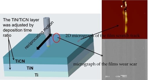
2.1. Specimens Preparation

The Ti/TiN/TiCN films were deposited in a closed field unbalanced reactive DCMS system. Argon (Ar) (99.99%) was used as work gas, and the gas mixture of nitrogen (N2) (99.99%) and methane (CH4) (99.99%) was used as reaction gas.
The details about the films deposited by the system can be found elsewhere [27]. The n-type Si (100) wafers with surface roughness of 20 nm were used as the substrate material. Before loading into the chamber, all of the substrates were ultrasonically cleaned in the ethyl alcohol and acetone for 10 min, respectively. The base pressure of the chamber was inferior to 6.5 × 10⁻⁴ Pa. The distance between substrate and target was 10 cm. The silicon substrates were sputter-cleaned using argon plasma before depositing. During deposition, the direct current and argon working flow rate were 4 A and 20 standard cubic centimeter per minute (sccm), respectively. The deposition time of the TiN layer ranged from 10 to 30 min. Due to the fact that the whole deposition time was 50 min, the deposition time ratio of TiN/TiCN was set at 28.57%, 50%, 80%, 125%, and 200%, hereinafter referred to as a-28, b-50, c-80, d-125, and e-200, respectively. The Ti/TiN films were also prepared for comparation, which is named f-TN for short. After deposition, the average roughness of these films was about 27 nm measured by a 2206-type surface roughness tester.

2.2. Films Characterization

The composition of the films was analyzed with a PHI-5702 x-ray photoelectron spectroscope (XPS) with monochromated Al Kα radiation at pass energy of 29.4 eV. X-ray diffraction (XRD) analysis was used to study the crystalline structure of the films on Philips X'perts diffractometer using Cu Kα radiation. Raman spectroscopy was obtained on a HR800 Raman microscope instrument, with 532 nm Ar ion laser and a resolution of 1 cm−1.

2.3. Properties

For adhesion evaluation, a scratch tester (Kaihua MFT-4000) was used. During scratch testing, the load was fixedly set at 30 N with a loading rate of 50 N/min. The critical load for adhesion failure was identified when a sudden change of the first order derivative of friction and audio frequency versus load curve was observed. The thin film stress distribution tester (BIOET BGS-6341) was employed to survey the internal stresses of the films by the radius of curvature technique. The internal stress was calculated by the Stoney equation:
σ = 1 6 E s 1 v s h s 2 h c ( 1 R 1 1 R 2 )
where Es is Young’s modulus, vs is Poisson’s ratio of the substrate, and hs and hc denote the thicknesses of the substrate and films, respectively. Moreover, 1/R1 and 1/R2 are the substrate curvature radii before and after film deposition. The thickness of films was measured by field emission scanning electron microscopy (FESEM).
The tribological behavior of the samples was evaluated by using the reciprocating ball-on-disc UMT-2MT tribometer with the counterparts of the AISI52100 steel ball at room temperature and about a relative humidity of 25%. The diameter, surface roughness, and hardness of the steel ball were 3 mm, 0.02 μm, and 850 HV, respectively. All the tests were conducted at a revolving velocity of 600 rpm, a sliding stroke of 5 mm, and a load of 1 N. The wear volume was measured using Micro XAM-3D Surface Profile. Then, the wear rate was acquired from the wear volume divided by the total sliding distance and applied load. The wear scars of the films were observed by scanning electron microscope (SEM) in order to observe the wear mechanism.

3. Results

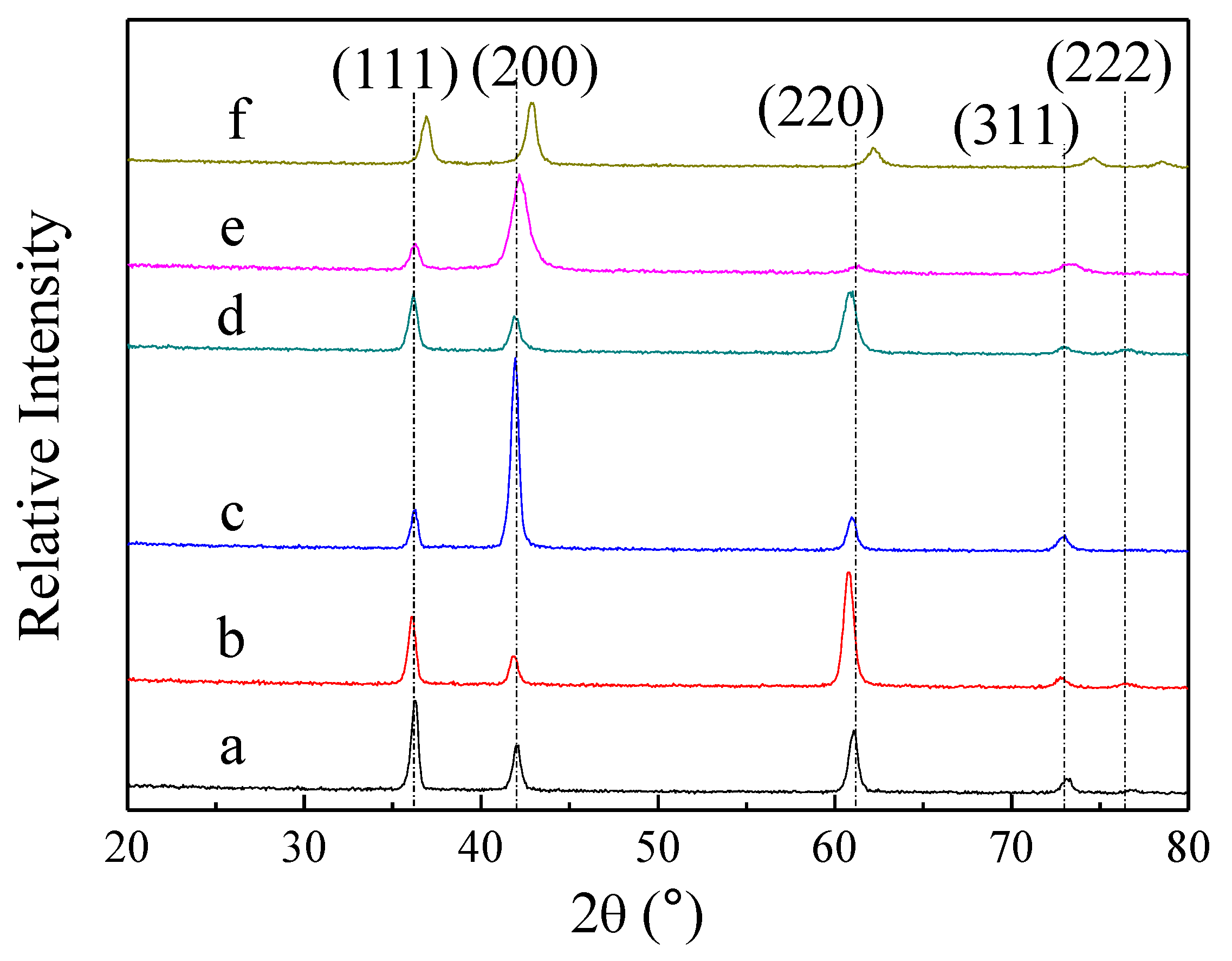
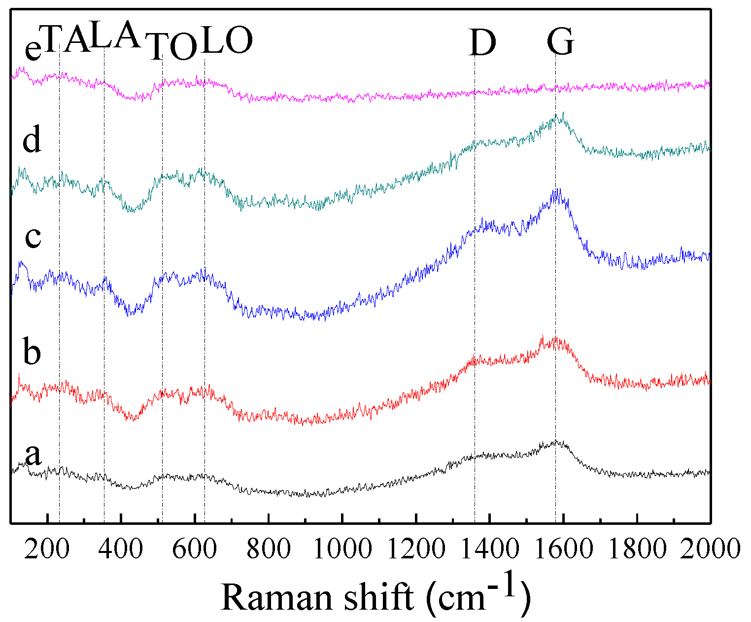
3.1. Composition and Microstructure

Table 1 provides the relative contents of titanium, carbon, nitrogen, and oxygen of the surface of the films deposited under different deposition time ratios ranging from 28.57 to 200% (a–e). One can find that the relative contents of titanium, nitrogen, carbon, and oxygen are slightly fluctuating in all films. It should be noted that oxygen is not deliberately introduced and its presence is attributed to the films that are exposed to the air resulting from the spontaneous oxidation process of Ti on the surface [28]. In addition, Sun C.Q et al. [29] have discussed that N reaction induced tensile stress on the surface and the C reaction induced compressive stress. It is estimated that film b should possess lowest tensile stress or highest compressive stress as shown in Table 1. Further study will be carried out through the later section.
XRD is used to investigate the crystalline structure of the Ti/TiN/TiCN films. Figure 1 depicts the XRD of the Ti/TiN/TiCN structure for films a-28, b-50, c-80, d-125, and e-200 and the Ti/TiNstructure for film f-TN. The whole deposition time and deposition time of the Ti layer were 50 min and 5 min in the Ti/TiN film. Five peaks corresponding to the (111), (200), (220), (311), and (222) plane of the cubic TiCN phase are observed in the films. A slight variation of intensity of the TiCN (311) peak with increasing deposition time ratio ranging from 28.57 to 200% is observed. After adding 21.43% of deposition time ratio from a to b, a significant increase in the intensity of the TiCN (220) peak and a reduction in the intensity of the TiCN (111) are seen, indicating a change in the preferred orientation from (111) to (220). However, for the films deposited with 80% and 200% of deposition time ratio, the relative intensity of the (111) and (220) peaks clearly drop, and the films exhibit an evident (200) preferred orientation. In addition, film d-125 merely shows a slight (220) preferred orientation. As seen in Figure 1, the XRD patterns of film f-TN display a significant shift of the peak positions to higher angles in relation to dash lines, indicating that the lattice spacing of the film was reduced. It is known that the lattice spacing of TiN and TiC is 0.4241 nm and 0.4329 nm, respectively. Therefore, the lattice is shrunk due to the formation of TiN phase instead of TiC phase [10]. In the films c-80 and e-125, the texture of the TiCN layer presents the preferential orientation (200) corresponding with the preferential orientation of the TiN layer. Moreover, the reflexes of films c-80 and e-200 belong to a face center cubic (FCC) lattice. This result suggests the possibility of a cube-on-cube epitaxial growth [8]. However, having an obvious preferential orientation (220), the TiCN layer of film b-50 restrains crystal growth of the TiN layer in the films. This result could hint that the films possess high hardness due to crystal lattice mismatching [30,31]. In Figure 1, some peaks of the films from a to e experienced a tiny shift of lower angles compared with the dash lines, due to the residual stress in the films [8].
It is known that Raman spectroscopy can provide information about the bonding configuration. Figure 2 shows the Raman spectra corresponding to different deposition time ratios of the films. It is worth noting that the Raman spectra of film e-200 did not show significant D (“disorder”, ~1360 cm−1) and G (“graphitic”, ~1560 cm−1) bands, indicating the absence of an amorphous carbon phase. The reason could be that the deposition time of the TiCN layer of film e-200 was too short and unable to obtain more C element. The result is in agreement with the data of XPS. In Figure 2, all films possess acoustical and optical modes [32]. Due to a slight change of element contents in all films, the shift of the peaks scarcely ever varies. However, the intensity changes are observed. Obviously, films b-50, c-80, and d-125 exhibit higher defect concentration in the films than the samples a and e, due to higher total peak intensity produced [32]. It could be ascribed to the effect of the deposition time ratio on the crystalline growth of the TiCN layer mentioned in the previous paragraph.

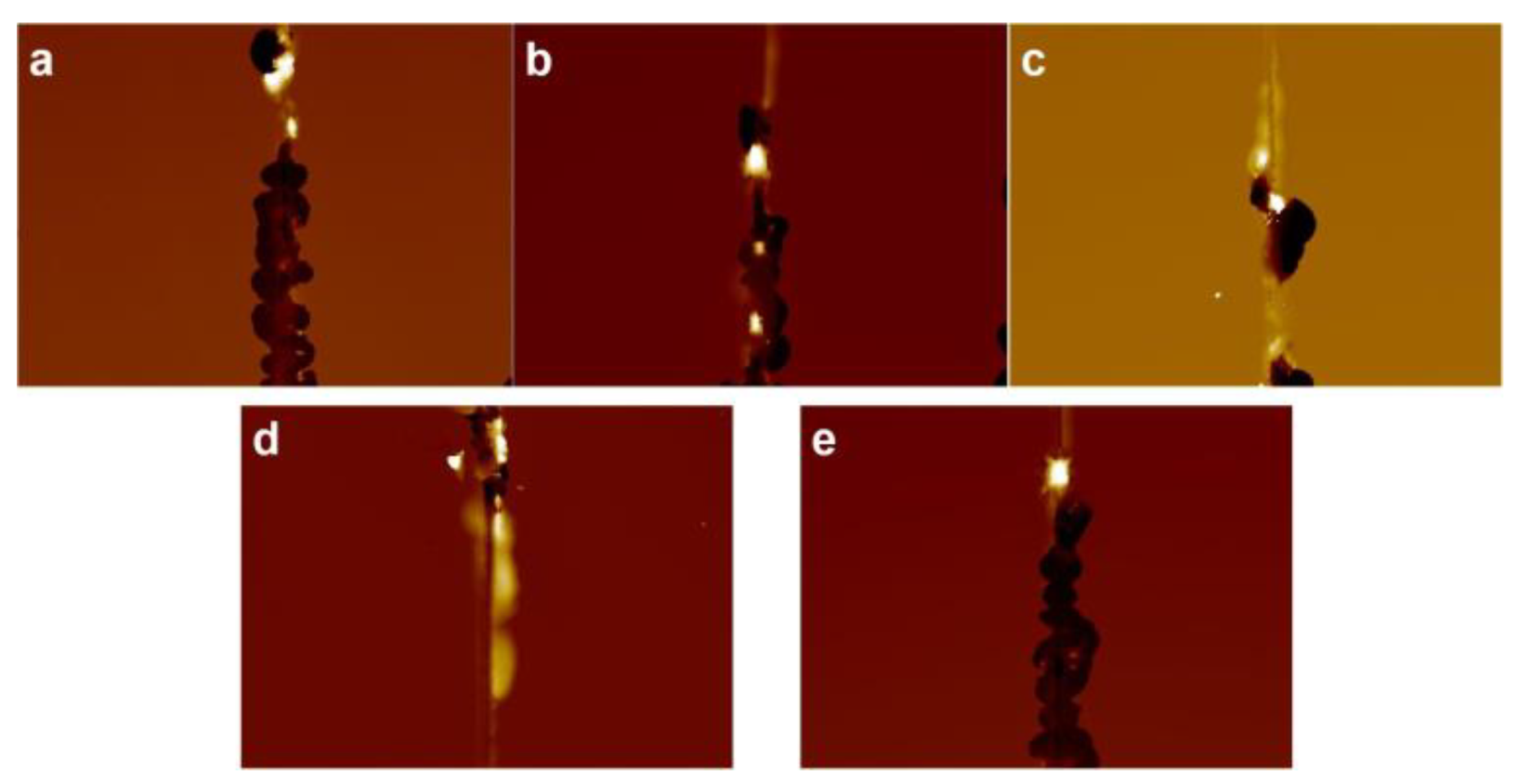
3.2. Stress and Scratch Test

In the films, substrate curvature is typically used to provide a measure of the average residual stress. Although the stress may not be uniform, the average value is a useful metric for comparing trends in processing parameters [33]. Average residual stress as a function of deposition time ratio for the Ti/TiN/TiCN films is plotted in Figure 3. As we have seen, the average stress with different deposition time ratio has a significant change. Above all, the average stress of all films is the tensile stress. With increasing the deposition time ratio, the average stress of the films firstly declines, then increases, and finally declines. However, film b-50 deposited on deposition time ratio of 50% displays the lowest average stress on account of the maximum contents of carbon and the minimum contents of nitrogen in the film. On the other hand, film b-50 has an obvious preferential orientation (220) than other films. This results in a vast alteration in the stress aspect [34]. Due to the thinner TiCN layer, the loose surface of film e-200 has easy oxidation. As a result, the compression stress for film e-200 increases when the film is exposed to air [35,36]. Therefore, the average stress of film e-200 has a sudden decrease compared with that of film d-125. Further experimental explorations will be carried out in the later research.
Table 2 presents the results obtained from the scratch test performed on the films. The COF and the width of the scratch track corresponding to the critical load Lc are also included. However, it is worth to point out that the film thickness, friction coefficient at Lc, and residual stress are the main factors that have a large effect on Lc [37]. Since there is no appreciable difference for the COF of all the films in Table 2, the adhesion strength is primarily dependent on the residual stress. For the films, the critical load firstly increases and then decreases as the deposition time ratio increases. This result mainly agrees with the conclusion of average stress. However, the result of the scratch test for film e-200 is inconsistent with the previous conclusion. It can be attributed to the fact that the structure of the film is loose, and a mass of oxidation products leads to bad scratch behaviors.
Figure 4 reveals 2D micrograph mapping for the failures in each film. It is worth noting that the failures of all films are brittle failures, which propagated along or near the interface, causing spalling of the films inside and at the edges of the scratch track. For films c-80 and d-125, the main failure mode is recovery spallation [37], which gave rise to chipping at the track edge. Nevertheless, the adhesion failure mode of films a-28, b-50, and e-200 was buckling ahead of the stylus [37]. As seen in Figure 4a-e, the dark portion of the picture was the adhesion failures inside the track. These results suggest that films a-28, b-50, and e-200 present better homogeneous structure than other films.

3.3. Tribological Properties

The COF of the film is continuously recorded during the wear tests and plots as a function of sliding time for films prepared under different deposition time ratios as shown in Figure 5. During the 30 min sliding test, three stages of the evolution processes of COF can be observed. Firstly, the COF for each film is extremely high in the initial stage due to forming the oxidation layer on the film surfaces [38]. However, the time of the initial stage of film b-50 was 50 sec, which was shorter than that of other samples. This is because film b-50 has a dense microstructure leading to it being difficult to be oxidated relative to other samples. Then, the lubricant stage corresponding to the value of COF is stabilized at a low value after the oxidation layer wears out. It should be noted that films a-28 and e-200 maintain extremely high COF in the whole sliding process unlike films b-50, c-80, and d-125 owning a lubricant stage. It can be attributed to the fact that the TiN layer for film a-28 is thinner than other films leading to it being unable to support the TiCN layer when the film is sliding against a steel ball. So, the lubrication for film a-28 becomes invalid fleetingly. However, film e-200 possessed high COF due to the thinner TiCN layer than other samples. Among films b-50, c-80, and d-125, the average COF of the lubricant stage is about 0.139. However, the COF curve of film b-50 hardly fluctuated compared with films c-80 and d-125. It is indicated that film b-50 has more stable tribological behavior. Finally, the invalid stage corresponding to the COF moves from a low value to a relatively higher value and the COF curve has significant fluctuation. As seen in Figure 5, the COF of films b-50 and d-125 begins to ascend slightly between 1600 and 1800 sec. During this period, the COF of film c-80 varies little. These results present that film b-50 deposited under deposition time ratio of 50% remains in the lubricant stage.
The wear volume of the films is measured with a 3D surface profiler. Table 3 summarizes the wear rate of all the films, and Figure 6 displays wear scar of the films sliding against steel balls. According to the figures in Table 3, the wear rate of film a-28 is highest, which is two hundred times higher than film b-50. However, it could be observed that film b-50 has good tribological performance with values for the wear rate as low as 1.163 × 10⁻⁶ mm3·m−1·N−1 sliding in the 30 min. As seen in Table 3, the deposition time ratio of film b-50 is 50% and represents 1.75 times that of film a-28. It is indicated that the film deposited under the low deposition time of TiN layer has lack of supporting for the TiCN layer. However, with increasing the deposition time ratio, the wear rate of the films appears as a slowly rising trend. Due to possessing relatively low adhesion strength and different crystalline orientation compared with film b-50, films c-80, d-125, and e-200 possess less resistant wear. It also could be explained that the deposition time of the TiCN layer is too short to form efficient lubricate. Generally, the deposition time ratio of the film is a determining factor in its resistant wear performance.
In Figure 6, it is worth noting that all films, with the exception of film a, have relatively smooth and neat wear scar. As illustrated in Figure 6a, the wear debris and particles are observed in the wear scar of the film and the edges of the wear scar have large flaking. It is suggested that adhesive wear shows in the contact surface and adheres to the film, which forms an overlapped transfer layer that induces severe wear [27]. Moreover, the delamination also appears in film a-28. As a result, film a-28 has extremely bad tribological behavior. In Figure 6, the width of the wear scar of film b-50 is shorter than the other samples. In addition, no concave-convex is surveyed on the edges of the wear trace of films b-50, c-80, and d-125. A similar wear mechanism could occur in films b-50, c-80, and d-125 due to similar COF, wear rate, and wear scar. Film e-200 possesses obvious wear debris and slight concave-convex.

4. Conclusions

The Ti/TiN/TiCN triple-layer films were deposited under different deposition time ratios by direct current reactive sputtering titanium target. With varying the deposition time ratio, the composition, crystalline structure, and bonding structure of the films were researched, and the properties of the Ti/TiN/TiCN films were investigated in detail. The main results can be summarized as follows:
  • The composition and bonding structure of the films only slightly changed, while crystalline structure was of significant variation with the deposition time ratio. The film deposited under deposition time ratio of 50% had an obvious change in the preferred orientation from (111) to (220).
  • The adhesion strength and internal stresses were closely related to the deposition time ratio. The film deposited under deposition time ratio of 50% had an optimal value of adhesion strength. However, the stress curve firstly declined, then increased, and finally declined.
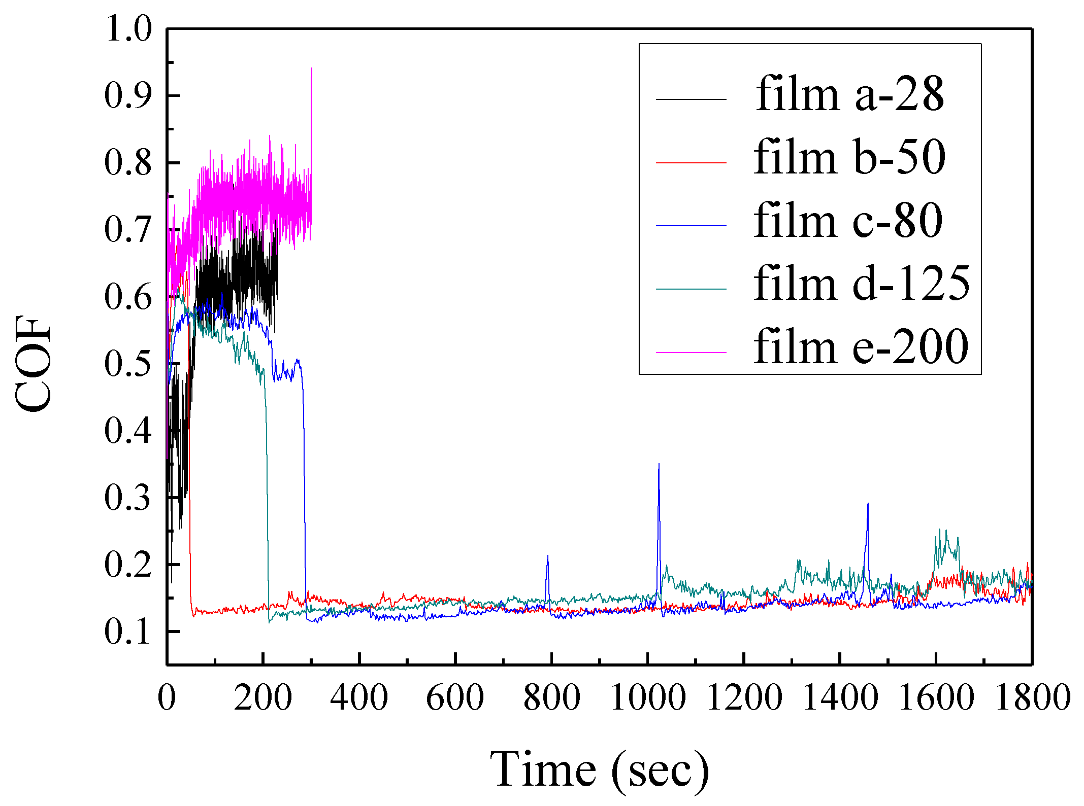
  • The COF of the films was divided into the three stages: initial stage, lubricant stage, and invalid stage. The COF curve included the stages when the films were deposited under deposition time ratios of 50% and 125%. Among the films, the COF was about 0.139 in the steady stage.
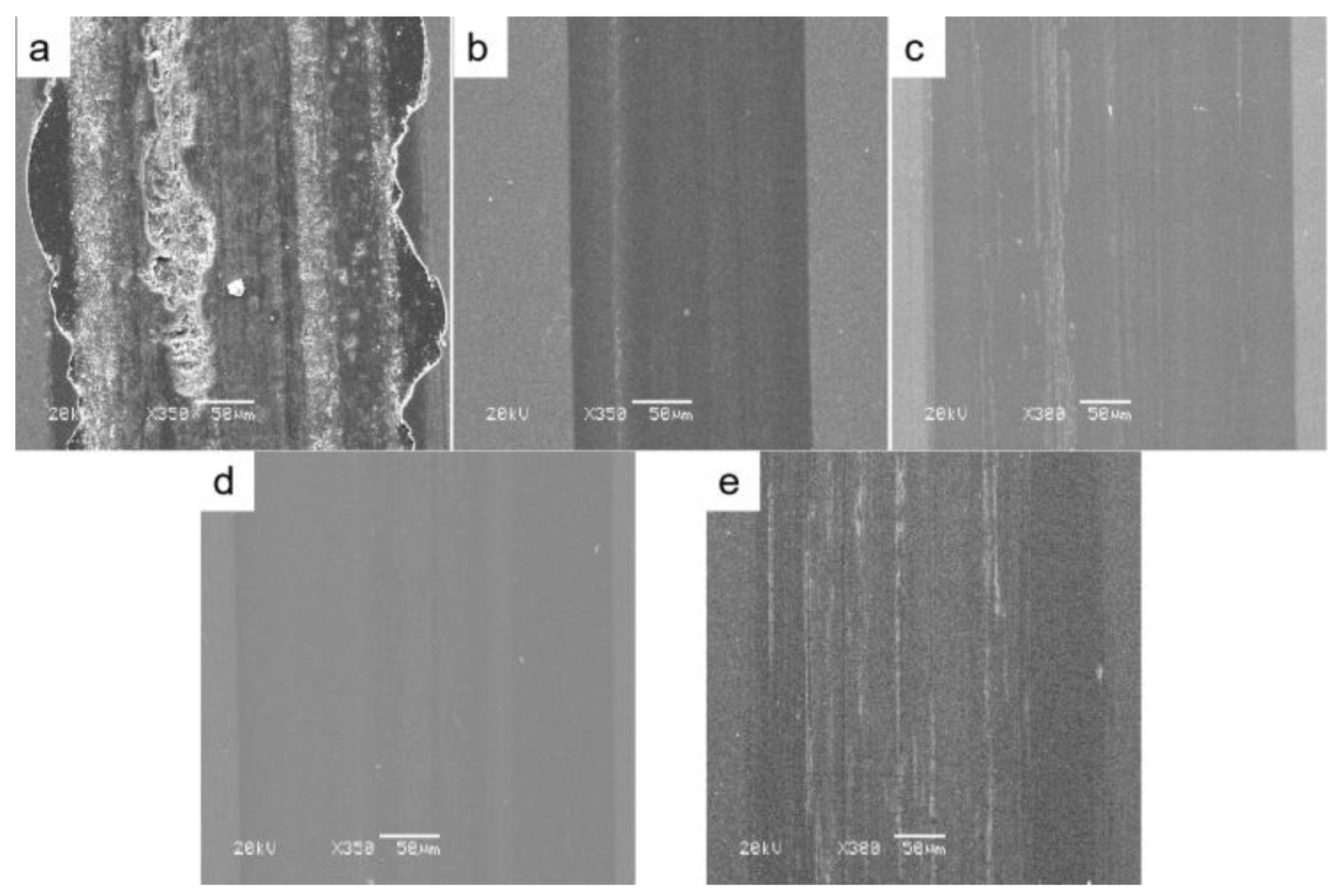
  • The films deposited under deposition time ratio of 50% was of lower wear rate than the other samples, which was 1.163 × 10⁻⁶ mm3·m−1·N−1. Moreover, the width of its wear scar was shorter.

Author Contributions

Conceptualization, methodology, software, validation, formal analysis, investigation, resources, data curation, writing—original draft preparation, and writing—review, Y.L. (Yanhong Lyu); editing, Q.Z., Y.L. (Yang Liu), X.D., H.S. and Y.L. (Yanhong Lyu); supervision, Y.L. (Yanhong Lyu); project administration, Y.L. (Yanhong Lyu) and M.M.; funding acquisition, Y.L. (Yanhong Lyu). All authors have read and agreed to the published version of the manuscript.

Funding

This research was funded by Provincial Natural Science Foundation of Hunan, China (Grant Nos. 2021JJ40140, 2021JJ30170), and the Scientific Research Fund of Hunan Provincial Education Department, Hunan, China (Grant Nos. 21B0812, 21A0580).

Conflicts of Interest

The authors declare no conflict of interest.

References

  1. Mekgwe, G.N.; Akinribide, O.J.; Akinwamide, S.O.; Olubambi, P.A. Fabrication of graphite reinforced TiCxNy by spark plasma sintering technique: A comparative assessment of microstructural integrity and nanoindentation properties. Vacuum 2021, 187, 110144. [Google Scholar] [CrossRef]
  2. Kumar, C.S.; Patel, S.K. Effect of duplex nanostructured TiAlSiN/TiSiN/TiAlN-TiAlN and TiAlN-TiAlSiN/TiSiN/TiAlN coatings on the hard turning performance of Al2O3-TiCN ceramic cutting tools. Wear 2019, 418–419, 226–240. [Google Scholar] [CrossRef]
  3. Polcar, T.; Novak, R.; Siroky, P. The tribological characteristics of TiCN coating at elevated temperatures. Wear 2006, 260, 40–49. [Google Scholar] [CrossRef]
  4. Cheng, Y.H.; Browne, T.; Heckerman, B. Influence of CH4 fraction on the composition, structure, and internal stress of the TiCN coatings deposited by LAFAD technique. Vacuum 2010, 85, 89–94. [Google Scholar] [CrossRef]
  5. Yang, Y.L.; Yan, W.; Zhang, D.; Song, G.Z.; Zheng, Y.R. In Situ-Fabrication of TiCN Ceramic Coating on Titanium Alloy by Laser Cladding Technology. Key Eng. Mater. 2010, 434–435, 485–488. [Google Scholar] [CrossRef]
  6. Yang, Y.; Zhang, D.; Yan, W.; Zheng, Y. Microstructure and wear properties of TiCN/Ti coatings on titanium alloy by laser cladding. Opt. Lasers Eng. 2010, 48, 119–124. [Google Scholar] [CrossRef]
  7. Yang, Y.; Yao, W.; Zhang, H. Phase constituents and mechanical properties of laser in-situ synthesized TiCN/TiN composite coating on Ti-6Al-4V. Surf. Coat. Technol. 2010, 205, 620–624. [Google Scholar] [CrossRef]
  8. Caicedo, J.C.; Amaya, C.; Yate, L.; Gómez, M.E.; Zambrano, G.; Alvarado-Rivera, J.; Muñoz-Saldaña, J.; Prieto, P. TiCN/TiNbCN multilayer coatings with enhanced mechanical properties. Appl. Surf. Sci. 2010, 256, 5898–5904. [Google Scholar] [CrossRef]
  9. Agudelo, L.C.; Ospina, R.; Castillo, H.A.; Devia, A. Synthesis of Ti/TiN/TiCN coatings grown in graded form by sputtering dc. Phys. Scripta. 2008, T131, 014006. [Google Scholar] [CrossRef]
  10. Guruvenket, S.; Li, D.; Klemberg-Sapieha, J.E.; Martinu, L.; Szpunar, J. Mechanical and tribological properties of duplex treated TiN, nc-TiN/a-SiNx and nc-TiCN/a-SiCN coatings deposited on 410 low alloy stainless steel. Surf. Coat. Technol. 2009, 203, 2905–2911. [Google Scholar] [CrossRef]
  11. Klemberg-Sapieha, J.E.; Jedrzejowski, P.; Martinu, L. Mechanical and optical characteristics of superhard nanocomposite TiN/a-Si3N4 and TiCN/a-SiCN coatings produced by PECVD. J. Superhard Mater. 2007, 29, 147–152. [Google Scholar] [CrossRef]
  12. Balaceanu, M.; Braic, M.; Braic, V.; Pavelescu, G. Properties of arc plasma deposited TiCN/ZrCN superlattice coatings. Surf. Coat. Technol. 2005, 200, 1084–1087. [Google Scholar] [CrossRef]
  13. Sun, H.; Billard, A.; Luo, H.; Zheng, W.; Zheng, X.; Dai, M.; Lin, S.; Shi, Q.; Sanchette, F. Influence of carbon content on the mechanical properties of TiCN–Cu nanocomposite coatings prepared by multi-arc ion plating. Vacuum 2021, 187, 110139. [Google Scholar] [CrossRef]
  14. Wang, Q.; Jin, X.; Zhou, F. Comparison of mechanical and tribological properties of CrBN coatings modified by Ni or Cu incorporation. Friction 2022, 10, 516–529. [Google Scholar] [CrossRef]
  15. Rebelodefigueiredo, M.; Neidhardt, J.; Kaindl, R.; Reiter, A.; Tessadri, R.; Mitterer, C. Formation mechanisms of low-friction tribo-layers on arc-evaporated TiC1−xNx hard coatings. Wear 2008, 265, 525–532. [Google Scholar] [CrossRef]
  16. Xian, G.; Xiong, J.; Zhao, H.; Xian, L.; Fan, H.; Li, Z.; Du, H. Study on the growth and wear behavior of the TiAlN-based composite coating deposited on TiCN-based cermets with different binder phase. Wear 2020, 460–461, 203460. [Google Scholar] [CrossRef]
  17. Zhu, B.; Mardel, J.; Kelly, G.L. An investigation of tribological properties of CN and TiCN coatings. J. Mater. Eng. Perform. 2004, 13, 481–487. [Google Scholar] [CrossRef] [Green Version]
  18. Wei, C.H.; Lin, J.F.; Jiang, T.H.; Ai, C.F. Tribological characteristics of titanium nitride and titanium carbonitride multilayer films: Part I. The effect of coating sequence on material and mechanical properties. Thin Solid Films 2001, 381, 94–103. [Google Scholar] [CrossRef]
  19. Zheng, J.Y.; Hao, J.Y.; Liu, X.Q.; Gong, Q.Y.; Liu, W.M. TiN/TiCN Multilayer Films Modified by Argon Plasma Treatment. Appl. Surf. Sci. 2013, 280, 764–771. [Google Scholar] [CrossRef]
  20. Meng, J.; Lu, J.; Wang, J.; Yang, S. Tribological behavior of TiCN-based cermets at elevated temperatures. Materi. Sci. Eng. A 2006, 418, 68–76. [Google Scholar] [CrossRef]
  21. Morant, C.; Prieto, P.; Forn, A.; Picas, J.A.; Elizalde, E.; Sanz, J.M. Hardness enchancement by CN/TiCN/TiN multilayer films. Surf. Coat. Technol. 2004, 180–181, 512–518. [Google Scholar] [CrossRef]
  22. Zheng, J.Y.; Ren, X.D.; Hao, H.Y.; Li, A.; Liu, W.M. Carbon nanohoops as attractive toughening and lubricant agents in TiN porous films. Appl. Surf. Sci. 2017, 393, 60–66. [Google Scholar] [CrossRef]
  23. Alisir, S.H.; Evrensel, D. Investigation into Coating Structure and Wear Environment Effects on Tribological Properties of Pistn Ring Coated with Monolayer TiAlN and Multilayer TiN/TiAlN. J. Mater. Eng. Perform. 2022, 31, 1654–1666. [Google Scholar] [CrossRef]
  24. Wróblewski, P.; Rogólski, R. Experimental Analysis of the Influence of the Application of TiN, TiAlN, CrN and DLC1 Coatings on the Friction Losses in an Aviation Internal Combustion Engine Intended for the Propulsion of Ultralight Aircraft. Materials 2021, 14, 6839. [Google Scholar] [CrossRef]
  25. Ruan, H.T.; Wang, Z.Y.; Wang, L.; Sun, L.L.; Peng, H.; Ke, P.L.; Wang, A.Y. Designed Ti/TiN sub-layers suppressing the crack and erosion of TiAlN coatings. Surf. Coat. Technol. 2022, 438, 128419. [Google Scholar] [CrossRef]
  26. Wróblewski, P.; Koszalka, G. An Experimental Study on Frictional Losses of Coated Piston Rings with Symmetric and Asymmetric Geometry. SAE Int. J. Engines 2021, 14, 85386. [Google Scholar] [CrossRef]
  27. Su, Y.L.; Kao, W.H. Tribological behavior and wear mechanisms of Ti-C: H/TiC/TiCN/TiN/Ti coatings when sliding against steel, bronze and aluminum alloy rods. J. Mater. Sci. 2001, 36, 189–199. [Google Scholar] [CrossRef]
  28. Talib, R.J.; Toff, M.R.M.; Ariff, H.M. Wear mechanism of TiN, TiAlN and TiCN coated drills during drilling of carbon steel. J. Phys. Sci. 2007, 18, 75–85. [Google Scholar]
  29. Sun, C.Q.; Fu, Y.Q.; Yan, B.B.; Hsieh, J.H.; Lau, S.P.; Sun, X.W.; Tay, B.K. Improving diamond–metal adhesion with graded TiCN interlayers. J. Appl. Phys. 2002, 91, 2051–2054. [Google Scholar] [CrossRef]
  30. Lackner, J.M.; Waldhauser, W.; Ebner, R.; Bakker, R.J. Chemistry and microstructure of PLD (Ti,Al)CxN1-x coatings deposited at room temperature. Appl. Phys. A 2004, 79, 1469–1471. [Google Scholar] [CrossRef]
  31. Peters, A.M.; Nastasi, M. Effect of carrier gas on the deposition of titanium carbo-nitride coatings by a novel organo-metallic plasma immersion ion processing technique. Vacuum 2002, 67, 169–175. [Google Scholar] [CrossRef]
  32. Dreiling, I.; Stiens, D.; Chassé, T. Raman spectroscopy investigations of TiBxCyNz coatings deposited by low pressure chemical vapor deposition. Surf. Coat. Technol. 2010, 205, 1339–1344. [Google Scholar] [CrossRef]
  33. Detor, A.J.; Hodge, A.M.; Chason, E.; Wang, Y.M.; Xu, H.W.; Conyers, M.; Nikroo, A.; Hamza, A. Stress and microstructure evolution in thick sputtered films. Acta Mater. 2009, 57, 2055–2065. [Google Scholar] [CrossRef]
  34. Abadias, G. Stress and preferred orientation in nitride-based PVD coatings. Surf. Coat. Technol. 2008, 202, 2223–2235. [Google Scholar] [CrossRef]
  35. Shi, Y.L.; Peng, H.R.; Xie, Y.; Xie, G.W.; Zhao, C.; Li, S.Z. Plasma CVD of hard coatings Ti(CNO) using metallo-organic compound Ti(OC3H7)4. Surf. Coat. Technol. 2000, 132, 26–30. [Google Scholar]
  36. Stanishevsky, A.; Lappalainen, R. Tribological properties of composite Ti(N,O,C) coatings containing hard amorphous carbon layers. Surf. Coat Technol. 2000, 123, 101–105. [Google Scholar] [CrossRef]
  37. Bull, S.J.; Bhat, D.G.; Staia, M.H. Properties and performance of commercial TiCN coatings. Part 2: Tribological performance. Surf. Coat. Technol. 2003, 163–164, 507–514. [Google Scholar] [CrossRef]
  38. Mo, J.L.; Zhu, M.H. Sliding tribological behaviors of PVD CrN and AlCrN coatings against Si3N4 ceramic and pure titanium. Wear 2009, 267, 874–881. [Google Scholar] [CrossRef]
Figure 1. X-ray diffraction patterns of the films with deposition time ratio. (a) film a-28; (b) film b-50; (c) film c-80; (d) film d-125; (e) film e-200.
Lubricants 11 00021 g001
Figure 2. Raman spectra for the films with different deposition times. (a) film a-28; (b) film b-50; (c) film c-80; (d) film d-125; (e) film e-200.
Lubricants 11 00021 g002
Figure 3. Average residual stress as a function of deposition time ratio for TiCN films.
Lubricants 11 00021 g003
Figure 4. 2D micrograph of the film scratch tracks at critical load: (a) film a-28; (b) film b-50; (c) film c-80; (d) film d-125; (e) film e-200.
Lubricants 11 00021 g004
Figure 5. The coefficient of friction curves of the films against steel balls.
Lubricants 11 00021 g005
Figure 6. SEM micrograph of the films wear scar. (a) film a-28; (b) film b-50; (c) film c-80; (d) film d-125; (e) film e-200.
Lubricants 11 00021 g006
Table 1. Thickness and surface elemental composition of the films measured by FESEM and XPS.
Deposition Time RatioThickness
(μm)
Ti (at. %)C (at. %)N (at. %)O (at. %)
28.572.124.2141.8513.9519.99
50.002.225.5545.3211.7817.35
80.002.422.7944.4411.2821.49
125.003.124.3944.7712.6818.16
200.003.325.5938.9315.5419.94
Table 2. Scratch test results from films a-28 to e-200.
FilmCritical Load, Lc (N)Friction Coefficient at Lc, μcScratch Track Width at Lc, wc (mm)
a-2817.9 ± 3.30.380.1795
b-5018.6 ± 1.50.400.1632
c-8017.0 ± 2.10.390.1702
d-12515.8 ± 0.80.380.2123
e-20012.0 ± 2.50.360.2145
Table 3. Wear rate of films with deposition time ratio ranging from 28.57 to 200%.
SamplesDeposition Time Ratio (%)Wear Rate against Steel Balls (×10−6 mm3/N·m)
a-2828.57224.7
b-5050.001.163
c-8080.001.196
d-125125.002.668
e-200200.005.800
Disclaimer/Publisher’s Note: The statements, opinions and data contained in all publications are solely those of the individual author(s) and contributor(s) and not of MDPI and/or the editor(s). MDPI and/or the editor(s) disclaim responsibility for any injury to people or property resulting from any ideas, methods, instructions or products referred to in the content.

