
A Review on Sliding Vane and Rolling Piston Compressors


School of Mechanical and Aerospace Engineering, Nanyang Technological University, 50 Nanyang Avenue, Singapore 639798, Singapore
*
Author to whom correspondence should be addressed.
Machines 2021, 9(6), 125; https://doi.org/10.3390/machines9060125
Submission received: 16 May 2021
/
Revised: 16 June 2021
/
Accepted: 17 June 2021
/
Published: 21 June 2021
(This article belongs to the Section Machine Design and Theory)
Abstract
:Rotary compressors have been employed in heating and cooling for more than a century and are ubiquitous in daily life but there has not been any comprehensive record of their development and technological advances. This review paper attempts to provide a comprehensive account of the advances in R&D and design evolution of these rotary compressors since their inception, namely the sliding vane compressor, rolling piston compressor, and their design variants in open literature. This is to showcase the current state-of-the-art for these compressors so that researchers can use it as a basis for future work. Based on authors’ insight, inter-disciplinary research combined with advancements in ‘disruptive’ technology such as artificial intelligence and advancements in additive manufacturing might be a promising research direction to bring about improvements in rotary compressor performance to meet mankind’s growing needs for cooling and heating applications.
1. Introduction
The vapor-compression system was first invented in 1834 by Jacob Perkins but it was not until 1856 when James Harrison found commercial success with his vapor-compression refrigeration system [1].
Since then, it has evolved and become inseparable from our daily life, be it for comfort, food preservation, and medical usage. The most widely used air-conditioning system today is the vapor compression system and the most important components are the evaporator, the condenser, the expansion valve, and the compressor, the last of which is responsible for driving the entire system. This review focuses on the development of the positive displacement compressors, in particular the rotary vane compressors.
The compressor is a device that does work on a fluid to increase its pressure. It is broadly classified into dynamic compressors, whereby momentum is imparted to the fluid via moving blades or impellers as kinetic energy is converted to pressure energy, and positive displacement compressors whereby volumetric changes are used to displace fluid and increase pressure.
Typically, dynamic compressors operate at higher speeds (>5000 rev min−1) in order to generate the desired pressure increase in the fluid. On the other hand, positive displacement compressors can operate at much lower speeds (600–3000 rev min−1 with variable speed versions operating up to 7500 rev min−1, occasionally) due to the nature of their working principle and are able to achieve a much higher compression ratio per single stage of compression. In fact, all small and medium (≤15 kW) vapor-compression systems today utilize positive displacement compressors.
Positive displacement compressor designs are numerous, ranging from reciprocating compressors such as the piston and diaphragm machines to rotary compressors such as screw, vane, rolling piston, and scroll machines. Compared to reciprocating compressors, rotary positive displacement compressors are more compact and less susceptible to vibration issues. These attractive features make rotary compressors the most popular and widely used positive displacement compressors today.
Since their inception, research on rotary compressors has led to improvements and improvisations for the ever-changing needs of the industry and society such as performance improvements, expansion of application areas, or even phasing out refrigerants due to environmental concerns [2] and requiring more research on adapting to new refrigerants. As research progressed, the magnitude of performance improvements began to be marginally incremental.
In addition, at the turn of the 21st century, the high dependency on fossil fuels, a finite and fast-depleting resource [3], has increased pressure on the need for renewable energy and/or energy-efficient/saving devices. It is therefore unsurprising that many design variants or new designs were conceptualized to bring about significant improvements [4], with research branching towards analysis of these new variants/designs. With the advent of computer-aided engineering (CAE), it has greatly aided and accelerated the design and development of compressors to keep up with the ever-changing needs.
A timeline on the development and environmental concerns which directed and accelerated research pertaining to vapor-compression systems and rotary compressors is presented in Table 1.
The early studies of compressors begun with physical measurement of their performance. It was only not until early 1970s when advancements in digital computing gave rise to the use of computer aided research. Initially, simplified mathematical models assuming ideal gas, adiabatic, and perfectly sealed processes were formulated. It was only later when computational power improved, more comprehensive mathematical models were developed to include physical phenomena such as heat transfer and leakage for accuracy. However, these were still mainly purposed built lump parameters models (zero dimensional).
Subsequently, when powerful computational resources became more readily available, more comprehensive 2 and 3 dimensional spatial and time dependent models began to surface, giving rise to finite element modeling (FEM) and computational fluid dynamics (CFD) modeling studies. Both FEM and CFD models can be combined into a fluid–solid interaction (FSI) coupled analysis to study their effects on each other. These computational simulation studies were extremely useful in visualizing fluid and/or heat flow to better understand the intricacies of rotary compressors.
This review is about the research and development aspects of rotary vane positive displacement compressors available in open literature, focusing on sliding vane and rolling piston compressors with their design variants. Screw (helical rotors) and scroll (orbiting scroll profiles) compressors are not included.
In presenting the development and evolution of these rotary compressors, their working principles are first explained, followed by documenting their various engineering aspects before ending with the design modifications or variants proposed and studied in efforts to improve compressor performance.
2. The Sliding Vane Compressor
One of the earliest sliding vane designs was patented in 1874 [5]. A rotor that houses free sliding vanes would rotate within a stator that can be either elliptically or cylindrically shaped. The rotor is in the center of an elliptical stator and eccentrically located in a cylindrical stator to form the working chambers. When the rotor rotates, the varying chamber volume creates the suction and compression effect. Figure 1 shows the different schematics of the sliding vane compressor.
In its basic form, sliding vane compressors required no suction or discharge valves and were designed to operate in accordance to its built-in volume ratio. Any off-design operating conditions would result in either under or over compression. To overcome this problem, a discharge valve was recommended [15] and it widened [16] the range of operating pressures.
The sliding vanes were initially fabricated from polyimide [9] and phenolic resin laminates [17], which are unsuitable for high pressure and temperature operation since these non-metallic vanes tend to warp and are thus unreliable. These issues were solved in 1961 when Worthington Compressors introduced metallic vanes [17].
The vane tip must always maintain contact with the inner chamber wall during operation. When this is not the case, mostly caused by pressure forces acting at the vane tip, significant internal leakages occur, and subsequently followed by knocking noise when the vane tip re-stablishes the contact with the inner cylinder wall. This phenomenon is known as vane chattering which was first investigated by Tojo et al. [18] in 1978. This phenomenon can be overcome by introducing high fluid pressure at the back of the vane to counteract the chamber pressure forces at the tip [19].
The sliding vane compressors found application in areas where the pressure pulsation, vibration, and noise tolerance are low, such as in automobile, aeronautical, and air-compression. In addition, sliding vane compressors are able to operate at low speeds to reduce friction loss without greatly affecting its volumetric efficiency [20]. However, due to its multiple-vane design, it still experiences high frictional losses caused by rubbing at the vane slots and at the vane tips, as compared to those with single vane designs, such as the rolling piston compressor.
2.1. Performance
In-chamber pressure measurements are required for evaluation of sliding vane compressors, and this was initially achieved by mounting a pressure sensor on the rotating rotor and transmitting the signal though the slip-ring or slip ringless transmitters [15,21]. Subsequently, these pressure measurements were correlated to the rotational angular position of the rotor using an encoder [22].
In 1978, Tothero and Keeney [23] measured the performance of 4-vane sliding compressors for automotive air-conditioning and noted that their performance was better than that of the two-cylinder reciprocating compressors, with volumetric efficiencies of 81% as compared to 67% achieved by the reciprocating compressors. However, Tassou and Qureshi [24] later found that the volumetric efficiency and overall performance of the sliding vane compressor were poorer than that of the reciprocating compressor due to the large frictional losses at the vane tips. As compared to screw compressors [25], though having the same energy consumption, sliding vane compressors have the additional advantage of having the ability to operate at low speeds to improve mechanical efficiency.
Table 2 summarizes the measured performance for the sliding vane compressor available in open literature.
2.2. Engineering
In the early 1970s [10], mathematical models of the sliding vane compressor were simplified lumped parameter models. Subsequently, more comprehensive models [20,28] employing real gas characteristics, accounting for internal leakages [29,30], in-chamber heat transfer, prediction of component temperatures, friction [31], dynamics [32], vibration [33], oil circulation [34], and even oil injection models [35] were formulated.
Thereafter, three-dimensional computation models employing numerical mathematics such as CFD modeling were used [36,37]. Advanced simulation processes involving dynamic meshing technique with moving boundary solution domains for the sliding vane working chambers were detailed by Bianchi et al. [36].
2.2.1. Optimization
The availability of mathematical models paved the way for computerized design optimization studies. In such a study, the purpose of the optimization (or objective function) must first be specified. The design variables, which can vary during the optimization process (often referred to as free variables), must be chosen within the specified ranges or constraints. Hence, constrained optimization approaches are often used. If the optimization approach allows more than one objective function to be described in its organic way, it is referred to as a multi-objective optimization approach. However, single objective optimization approach can always be used to optimize multi-objective problems by introducing the penalty functions into the objective function.
2.2.2. Vane Dynamics and Lubrication
The friction at the vane tips accounted for 80% of the overall vane friction loss [20] in the compressor. Early designs used non-metallic vanes, such as polyimide vanes which assumed Coulomb type friction with a friction coefficient of 0.11 at the vane tip [9]. As operating pressures and speeds increased, metallic vanes were introduced, and with the presence of the lubricating oil, hydrodynamic lubrication models were developed to study the oil film thickness and friction at the vane tips [17] and sides [40]. Under such conditions, the friction coefficient was measured to be 0.055 by Cipollone et al. [27] and an empirical value of 0.065 was obtained by Bianchi and Cipollone [20] in another study. Lubrication is highly dependent on operating conditions and working fluids; Basaj [41] noted these intricacies of lubrication failure mechanisms and recommended lubricants based on different conditions. In general, lubricating oil film is often difficult to form in practice, as the vane tip contact points constantly varies, and the situation is worsened by variation of pressure forces acting on the vane during the compressor operation.
2.3. Design Variants
2.3.1. Injection Mechanisms
In 1980, Kruse [15] introduced oil injection to reduce the vane tip friction, which reduced the driving torque for speeds up to 1500 rev min−1. It was found that the conventional oil injection method had negligible effects on cooling the compressor [44]. To improve the cooling effect, Cipollone et al. [44] used a pressure swirl injector to atomize the oil prior to injection and found that the power consumption was reduced by 7%. Alternatively, liquid refrigerant injection can also be used to cool the compressor as demonstrated by Hickman and Neal [45] in 1984.
A summary of the performance for the sliding vane compressor with injection mechanisms is shown in Table 3.
2.3.2. Design Variations
To further improve the performance of sliding vane compressors, design improvements were introduced such as a slider mechanism presented by Taguchi et al. [46] for improving suction loss at high operating speeds in automotive applications.
To reduce frictional losses at the vane tips, Gu et al. [47,48] proposed a sliding vane compressor variant in which one of the vanes is connected to the cylinder such that it will rotate together with the rotor component. The relative velocities between the vane tips and cylinder walls are now lower, reducing frictional losses by up to 10.2%.
Another design variant [49] consists of two free sliding vanes within each slot to improve lubrication and sealing. In addition, Wang et al. [50] proposed the use of an asymmetrical cylindrical stator in which its profile was generated with an exponential spiral function to increase the compression ratio.
- Fixed Vane Variants
To solve the issue of vane chattering, a design variant with connecting rods that maintained the radial positions of the vanes was introduced by Smith and Harrison [51] which improved volumetric efficiency by 3%.
Another variant proposed by Edwards [52,53] eliminated vane tip friction by maintaining clearances between the vane tips and the stator wall. Sealing at the vane tips was achieved when centrifugal force filled the clearances with lubricant.
A summary of the performance for these fixed vane variants is shown in Table 4.
- 2.
- Spool Compressor
The spool compressor [54] was introduced in 2008 as a variant of vane compressor in 2008 with the intention to avoid vane tip contact at the chamber walls and reduce friction losses. Thereafter, spring loaded tip seals at the vane tips [55] and an end-face hybrid seal [56] were introduced to improve compressor volumetric efficiency. Another study explored the feasibility of using poppet valves to improve the discharge process in the spool compressor [57].
As development on the spool compressor continued, a dimensionless number that is the ratio of frictional loss to working volume known as the Zsoro number was introduced [58,59,60]. Mathematical models for predicting spool compressor performance were developed [61,62] and measurements and other analyses were also carried out to study the compressor performance [63,64,65,66,67].
Lastly, injection mechanisms for the spool compressor were investigated, with one utilizing multiple vapor injection ports [68] and another one with oil injection for oil flooded operation [69].
- 3.
- Coupled Vane Compressor
A new compressor called coupled vane compressor was presented in 2018 by Ooi and Shakya [70] as shown in Figure 2. Unlike all other rotary compressors available today, coupled vane compressor allows a very small rotor to be used, and hence, resulted in a very compact rotary compressor. This is achieved by allowing the vanes to diametrically pass through the rotor. Preliminary theoretical and measurement [71,72] showed that it has potential of reducing the pump end by at least 40% in physical size, which potentially saves a lot of materials in fabricating it.
3. The Rolling Piston Compressor
The rolling piston compressor was developed in the 1960s and it is the most widely compressor in room air conditioners (RAC) today. Mass production began in 1967 [8] by Toshiba. Today, the annual global production volume of this compressor has been consistently hovering around 200 million units from 2017 to 2020, with China producing approximately 90% of the total volume [73]. It is so widely used that the commercial term ‘rotary compressor’ is synonymous with the rolling piston compressor.
The rolling piston mechanism consists of a roller mounted on the eccentric cam of the driveshaft within a cylinder as shown in Figure 3. The vane and the contact between the roller and inner cylinder wall separate the suction chamber from the compression chamber. During operation, the driveshaft rotates and with it, the roller piston would orbit within the inner cylinder. The changes in volumes of the chambers would result in a suction and compression cycle of the fluid every two revolutions.
3.1. Performance
Since inception, the rolling piston compressor has boasted good efficiencies coupled with a compact and simple design. An example would be for water heater applications [65] where the rolling piston compressor outperforms the reciprocating compressor for all environmental conditions.
A summary of the performance for rolling piston compressors is shown in Table 5.
3.2. Engineering
Early mathematical models available in open literature provided comprehensive analysis which included internal leakage [11,74], friction [11], and thermodynamic loss models [74]. Thereafter, even more comprehensive models were introduced which included considerations for heat transfer, variations in lubricant oil viscosities, instantaneous chamber properties [76], and even leakage models for variable clearances [79]. In addition, CFD simulations are useful for visualization of the refrigerant flow [80] in the working chambers and better understand spatial variations of fluid properties.
Furthermore, empirical [81,82] and semi-empirical models [83] were also developed to simplify and shorten the computational time for modeling compressor performance. The semi-empirical model formulated by Molinaroli et al. [83] only required eight input parameters and had a performance prediction accuracy of ±5%. Another novel method of reproducing the cyclic pressure variation in the compressor was presented by Farkas et al. [84] and used mathematical functions for non-linear oscillators to curve-fit the pressure profile.
3.2.1. Optimization
To improve performance, it was recommended that reducing the mass of the piston would improve mechanical efficiency and vane reliability [85]. Efficiency charts were typically used to locate the maximum efficiency point [86,87,88]. Ishii et al. [86] found an optimum combination of parameters to achieve the highest mechanical efficiency based on a fixed volume but an optimum combination could not be found when both the volume and cylinder diameter parameters are fixed.
3.2.2. Transient Analysis
In early RACs, compressors were subjected to on-off mode to control the room temperature. The periodic starting operations can be termed as warm start-up. Hence, transient analysis of compressors was an important aspect of study. These mathematical models included start-up dynamics [91], mechanical and internal leakage losses [92]. Apart from theoretical analyses, experimental investigations were also conducted for warm start-up operations with R290 [93,94].
Another aspect would be cold start-up operations whereby the compressor is first started at low temperature conditions and the lubricant viscosity might be insufficient for lubrication [95]. Another concern would be the ingestion of liquid refrigerant from the evaporator and into the compressor during start-up operation [93,96]; as liquid is incompressible, the resultant pressure spike can damage the components when compression is attempted. Mitigation methods for this phenomenon would be to instigate a slow start and allow heat transfer in the working chamber to vaporize the liquid refrigerant [97] before transitioning to steady-state operation.
3.2.3. Heat Transfer
Heat transfer studies can be split into two categories. The first type focuses on heat transfer within and between compressor components, which utilized lumped mass or lumped thermal conductance models [98,99] to calculate steady-state operating temperatures. These models split the compressor into multiple elements which allow for calculation of temperature distribution within the individual components.
The second type focuses on in-chamber heat transfer between the working fluid and the chamber walls [100] which assumes homogenous temperature distribution of the fluid and is crucial for determining the thermodynamic efficiency of the compressor. Other than the Nusselt number correlation for in-chamber heat transfer, a flow visualization of the working fluid in the chamber is required to determine the characteristic length and velocity.
Subsequently, FSI simulations were carried out to combine the effects of both in-chamber and inter-component heat transfer. This provided an accurate representation of the entire spatial temperature distribution of the compressor during steady-state operation [101] and can even be extended to include the circulating effects of the lubrication network [102]. Another FEM study performed by Wu and Li [103] found large deformations in the cylinder component during operation due to non-uniform thermal and pressure loads but these deformations were beneficial in reducing leakage losses in the compressor.
3.2.4. Internal Leakage
Internal leakage occurs when high pressure fluid in the compression chamber leaks through clearances into the suction chamber and re-expanded. This cycle of compression and re-expansion is a waste of energy which also increases the temperature of the working chamber, further increasing energy consumption and may result in overheating.
Analytical studies that focused only on internal leakage can be broadly classified into either single-phase flow [104] or two-phase flow whereby either the working fluid or a homogenous mixture of working fluid and lubricant is assumed to leak, respectively. Another method would be to analyze the flow of oil through the clearances and derive the refrigerant leakage based on its solubility in oil [105].
Single-phase flow leakage models assume isentropic flow [11] with a correction term such as a flow coefficient [74,106] which can include viscous [107,108] and/or inertial effects [109] for accuracy. On the other hand, homogenous two-phase flow models assume thermal equilibrium [110] or isothermal conditions [111,112]. Additionally, spatially varying temperature distribution of the homogenous two-phase flow model [113] may be taken into consideration but increases model complexity.
Comparing both models, Cai et al. [114] concluded experimentally that no leakage model can single-handedly model the leakage across the wide range of operating and geometric variations. Subsequently, a semi-empirical two-phase leakage flow model was formulated, providing greater accuracy than theoretical flow models [115].
3.2.5. Compressor Dynamics and Vibration
As a rotary machine, the rolling piston compressor possesses better vibrational characteristics than the reciprocating compressor. However, due to the eccentric cam and its orbiting motion, the compressor may still be subjected to vibration which can be rectified with dampers [116] and/or rotational balancing [117]. Hence, the dynamics of the rolling piston compressor is another important area of study.
Early literature was focused on force analysis [118], friction [119], and compressor dynamics [120]. Subsequently, equations of motion for the rotational vibration [121,122] of the compressor were formulated, some of which focused on low-speed operation for a dual cylinder variant [123].
FEM is also used for modal and vibrational analyses [124,125,126] of the rolling piston compressor. These analyses were far more accurate than analytical models and could even account for whirling or deformation of the shaft due to dynamic loading during operation [125].
Acoustical analyses were carried out and found that discharge pulsation due to its cyclic discharge nature was the main source of noise instead of mechanical vibration [127,128,129,130]. An FSI simulation of the discharge valve [131] noted that the impact of the valve against the valve stop contributed to the noise as well. Noise arising from vibration of the components can be mitigated by directly reducing vibration, such as using dampers [116] or reinforcing the compressor housing and internal mounting structure [129].
3.2.6. Valve Mechanics and Port Flow
The discharge valve is a necessary component for regulating the discharge pressure by ensuring that the working fluid is discharged at the required pressure. However, it brings about discharge pulsation and unnecessary noise. These effects can be mitigated through discharge port design [128] and/or by using a discharge muffler [127,129].
Additionally, it also causes over-compression loss since more work is required to actuate the discharge valve. This was studied both analytically [132,133], experimentally [77,134], and with CFD simulations [130,131,135]. Methods to reduce loss would be to increase the number of discharge ports [136] or to implement valves that are easier to actuate, such as thinner and longer reed valves [137].
On the other hand, suction flow can potentially be another source of loss. This is known as suction loss whereby poor suction pipe and port design would hinder the intake of working fluid into the working chamber. This phenomenon was first studied analytically and experimentally in 1988 by Kakuda et al. [138]. It was found that the suction pipe geometry could be modified to take advantage of the pulsation effect and increase the suction flow rate. Subsequently, the study was extended to variable speed operation [139], thus improving the capacity and volumetric efficiency but at the cost of lower overall efficiency [140].
3.2.7. Vane Dynamics and Vane Tip Tribology
The spring-loaded vane has also been attempted to ensure vane tip contact is maintained. However, this is not popular since repetitive compression results in premature spring fatigue failure [141]. Additionally, the spring force is also insufficient to maintain vane tip sealing during operation due to high fluid pressure forces that push against the vane tip. To overcome this, discharge pressure is channelled to the back of the vane to counteract the vane tip fluid pressure. However, during start-up operation when discharge pressure is still building up, fluid pressure forces may overcome the spring force to break the seal, resulting in a vane jumping phenomenon [142].
As high forces are required to ensure a good vane tip seal, a trade-off results in the form of high frictional losses and wear. Early studies were focused on friction analysis between the vane and roller [110,118]. Subsequently, a tilted vane design was proposed and hypothesized to reduce vane tip losses, but this did not work well although it did reduce the wear rate [143].
Subsequently, lubrication models for the vane tip and roller interface were formulated, the earliest model employing the elastohydrodynamic lubrication (EHL) theory [144,145]. Subsequently, mixed lubrication models [146,147] were developed to better model the interface, with considerations for asperity contact [148,149,150] and for elastic deformation [151].
Wear occurs in the compressor can be accelerated by incorrect lubrication conditions. Tribological and wear studies [152,153,154,155] were performed to understand wear characteristics and estimate the wear rates for various combinations of refrigerants and lubricants. Other than wear at the vane tip, wear between the vane and slot was also observed. This causes the vane to eventually tilt and further aggravate wear [156]. To reduce wear, the use of material coatings such as titanium nitride (TiN) [144,157] or tungsten carbide [158] on the vane was proposed.
3.2.8. Compressor Lubrication
Apart from the vane tip and roller interface, lubrication is an important aspect for reliable compressor operation and lubricating oil also serves as a sealing medium at clearances to reduce internal leakage. Insufficient lubrication can result in elevated internal leakages and metallic contact at rubbing interfaces which increases wear, even causing seizures. Apart from engineering analysis and design to improve lubrication, nanocomposite lubricant additives can be introduced to improve lubrication performance by reducing friction coefficient and frictional heating [159].
Experimental lubrication studies include the determination of oil supply rate [160], oil foaming phenomenon [161], changes in oil viscosity due to refrigerant solubility [162], and effectiveness of the oil film for hydrodynamic lubrication [163]. A novel method that measured electrical resistance at rubbing interfaces was developed to evaluate lubrication conditions—a sharp drop in the measured electrical resistance would mean metallic contact at the interface, indicating lubrication failure [164]. In addition, a high-speed camera was also used to visualize the transient uptake of oil in the supply shaft during compressor starting operation [165].
Theoretical studies on oil flow through the radial clearance [166], bearing hydrodynamic lubrication [119,167] and lubrication network of the compressor [168,169,170] were also carried out. Hydrodynamic lubrication models and lubrication network models are used together, the former to determine the oil requirements, and the latter to ensure sufficient flow of oil. The mixed EHL model was also applied to analyze the coupled journal-thrust bearings [171] of the compressor to study its lubrication characteristics. A comprehensive CFD analysis of the entire compressor was also performed [172] to study the effects of lubrication on compressor performance.
During compressor operation, the miscibility of oil and refrigerant is crucial. Lubricant that is channelled into the working chamber for lubrication will mix with refrigerant vapor to form oil mist and refrigerant. Most of the oil mist will be separated before the discharge. Oil recirculation rate should be kept minimum to avoid oil depletion in the oil chamber for lubrication. Excessive oil circulation in the entire system will impair heat transfer at the heat exchangers or even clog the system.
3.2.9. Refrigerants
As the industry started to avoid using ozone-harming chlorofluorocarbon (CFC) refrigerants in the 1990s, the formulated mathematical models were useful for predicting compressor performance with new refrigerants to make design changes for adaptation to the new refrigerants. Due to the refrigerant changes, thermodynamic properties are now different, and the various aspects of the compressor would have to be re-evaluated. These included performance studies that were conducted on replacement refrigerants such as R134a, R502, R22 [178], and R410a [179]. Subsequently, these new replacement refrigerants with high global warming potential (GWP) will also be replaced. Naturally occurring fluid such as carbon dioxide [180] has also been attempted.
Additionally, with regards to compressor lubrication and internal leakage, characteristics and compatibility of the new refrigerants with lubricating oils would have to be assessed as well. The different solubility rates of the refrigerants would affect the viscosity, which may impair lubrication [181], especially at the vane tip [150].
Amongst the replacement refrigerants with low GWP, R290 was found to have the best performance [182] and in an investigation on two-phase compression in the event of liquid slugging [183], R290 also had the least detrimental effect on the compressor due to the large difference in its specific volume between the liquid and vapor phases. Extensive research on the performance of the rolling piston compressor with R290 was thus carried out, which included transient start-up investigations [93,94], and effects of component deformation [103] in lieu of the associated higher operating pressures.
For R290, its high solubility in polyalkylene glycol oil resulted in higher leakage losses [112]. Evaluation of lubrication performance using R290 with mineral oil was carried out at high ambient temperatures [184] along with reliability testing that indicate both mineral and synthetic oil are compatible with R290 [185] although higher friction coefficients were observed with mineral oil at the vane and roller interface [155]. Empirical correlations for the solubility of R290 in mineral oil and the resultant oil viscosity were also formulated [186].
3.3. Design Variants
To improve compressor performance, interesting design improvements were proposed in literature such as the addition of an oil stirrer [187,188] or tapered oil suction pipe [189] to improve oil flow and lubrication, or even a low-pressure shell design [190] to improve mechanical efficiency.
Furthermore, design changes can lead to the creation of variants; some of which include a miniature compressor with a capacity of only 1.4 cm3 [78], oil-free rolling piston [191], an oil-free variant with a swivel vane component to reduce vane tip friction [192] and even a hollow rotor variant to increase compressor capacity [193,194,195].
3.3.1. Dual Cylinder and Two-Stage Rolling Piston Compressors
In the interest of expanding the application of rolling piston compressor to handle higher capacity applications, the dual cylinder or twin cylinder design is introduced. Furthermore, the two cams are rotationally balanced, resulting in better vibration characteristics with lower amplitudes [196] and smaller bearing loads [197].
The earliest dual cylinder rolling piston design was presented by Sakaino et al. [196] in 1986. Since then, various engineering aspects of the dual cylinder rolling piston have been studied, which included dynamics [197], optimization [198], discharge flow [199], and lubrication [200]. With the phase out of harmful refrigerants, studies on dual cylinder performance [201] and lubrication [202,203] with new refrigerants were also carried out. Additionally, the performance of dual cylinder rolling piston in novel applications has been evaluated, such as in combination with a conventional rolling piston for two-stage compression [204], variable speed operation with vapor injection [205], and even two-stage compression with inter-stage injection [206].
Alternatively, the dual cylinder rolling piston can be used for two-stage compression systems instead. Each cylinder is designated as a separate stage, which conveniently combines the compressors for each stage into a single unit. It is useful in systems that require high pressure ratios such as that of the carbon dioxide cycle [207,208].
Experimental evaluations of the two-stage, dual cylinder rolling piston compressor were carried out which showed that it had higher cooling capacity and COP [209]. To improve performance, a novel capacity modulation method to control compressor operation depending on flowrate requirements was proposed [210] and better performance was obtained when compared to other systems [211]. In addition, an inter-stage vapor injection port was implemented into a two-stage, dual cylinder compressor and a 2% improvement in COP [212] was obtained.
A summary of the performance for the dual cylinder and two-stage rolling piston compressors is shown in Table 6.
3.3.2. Injection Mechanisms
Injection mechanisms were also introduced to improve performance in severe environmental conditions such as cooling in desert environments or heating in tundra environments. Refrigerant vapor is injected into the working chamber for cooling. This helps to increase the compressor capacity and COP of the system.
3.3.3. Compressor Orientation
The oil sump for lubrication is typically located at the lowest point in the compressor and this is a necessary requirement for the lubrication network to work. This would thus restrict the rolling piston compressor designs to a fixed orientation.
Therefore, in the development of the compressors for various orientation applications [217], lubrication systems would have to be redesigned. Some redesign works include utilizing the reciprocating vane motion as an oil pump [218,219] and formulating new mathematical models for these lubrication systems [220,221].
3.3.4. Swing Mechanism
In 1996, Daikin Industries [222] introduced the swing compressor where the vane tip friction was completely eliminated by fixing the vane onto the roller while the other free end would slide and pivot in the cylinder slot during operation.
Due to absence of vane tip friction, the swing compressor enjoys higher mechanical efficiency compared to the rolling piston especially at higher pressure ratios [223], better overall performance [222,224], and better lubrication characteristics [225]. It also possessed better efficiency than the scroll compressor at small capacity applications below 7.7 kW [224].
Development of the swing compressor included noise reduction for quieter operation [226,227] and adapting the mechanism to work with replacement refrigerants such as carbon dioxide [228] and R32 [229]. Other novel endeavors included the development for oil-less operation [230] and its leakage model [231].
Design variants for the swing compressor exist as well and some of these included a hollowed-out roller that increases the working volume [232], a redesigned discharge mechanism that removes the need for discharge valves [233,234,235], and the use of swivel vanes rather than fixed vanes. These swivel vanes can either be fixed onto the roller [236,237] or the cylinder [238,239]. Two swivel vanes may even be implemented to increase the displacement capacity per revolution [240]. Lastly, another novel variant modified the vane and slot mechanism into a U-shaped swivel slot with a shorter vane to reduce compressor size [241].
A summary of the performance for swing mechanism compressors is shown in Table 7.
3.3.5. Synchronal Rotary/Revolving Vane Compressor
Another novel variant would be the synchronal rotary compressor, otherwise known as the revolving vane compressor. It was first introduced by Qu et al. [242] in 2004 with the theoretical model for the geometry and working volume. Instead of the roller following an orbiting motion in the cylinder, it is now a rotor that is connected to the cylinder via a swivel vane and both the rotor and cylinder rotates together during operation. The co-rotating rotor-cylinder mechanism results in lower friction losses due to lower relative velocity between components. At the same time, vane tip friction is eliminated completely. The working principle of the revolving vane compressor is shown in Figure 4.
Another early design iteration of the mechanism was presented by Dreiman and Bunch [243] in 2006 with the vane fixed onto the cylinder and the mechanism driven via stator magnets as if it was a motor rotor instead.
The synchronal rotary mechanism was later adapted by Qu’s research team for multiphase pumping applications in which theoretical and experimental analysis for the mechanism with varying inlet gas fractions [244,245] was carried out complete with in-depth analysis for the suction port design [246] and optimization [247].
Subsequently, an experimental evaluation [248] and comprehensive model was presented in a series of literature which focused on frictional losses [249], rotating discharge valve dynamics [250], and leakage characteristics [251]. Further improvements to the compressor model included a two-phase flow leakage model [252], oil-free leakage model [253], in-chamber heat transfer model [254], end-face friction [255,256], and rotational vibration [257].
At the same time, design enhancements were made to the revolving vane compressor by replacing the original swivel vane with a fixed vane [258] to remove vane side friction losses and a bearing design method [259] for the compressor. Experimental validation showed that vane side friction only made up 2% of the overall frictional losses [260].
Lastly, a new variant of the revolving vane compressor was introduced by Yap et al. in 2014 [261,262] and shown to improve COP by 36.6% [263]. Known as the cross-vane expander-compressor (CVEC), it combines both the compression and expansion processes of the vapor compression cycle into a single device by hollowing out the rotor to function as a separate expansion working chamber.
A summary of the performance for synchronal rotary/revolving vane compressors is shown in Table 8.
4. Concluding Remarks and Future Outlook
This paper reviewed the different engineering aspects of rotary compressors and traced their developmental history. Initial development of these rotary compressors was born from and driven by industrial needs to showcase their superiority over reciprocating compressors. Since then, they became popular, further driving development and has been evolving and improving over the years, adapting to ever-changing industrial and societal needs.
In the pursuit of progress, compressor performance has improved by leaps and bounds although some of the more recent improvements may be incremental. New design variants inspired by these rotary compressors have been developed in attempts to provide further improvement in performance. Although Carnot machines are not feasible end-goals for such R&D, it is believed that irreversiblities in existing compressors can still be reduced with further research efforts.
Research and development is still going strong despite the technological maturity of the rolling piston and sliding vane compressors, although design variants and new rotary designs may be starting to take center-stage since they have more potential for significant improvements. Moreover, as society is being affected by worsening climate change at the turn of the 21st century, escalating needs for cooling and heating applications would warrant the development of compressors with increasing capacities. Additionally, with the focus on safeguarding the environment, development of ‘green’ compressors has also become more attractive.
Efforts towards improving energy efficiency for even ‘greener’ compressors include conventional engineering approaches such as optimization or design improvements. For example, the switch to environmentally friendly refrigerants would require optimization of existing compressor designs to adapt to these new refrigerants. However, as these conventional approaches mostly bring about incremental improvements, more novel ideas would be required to advance these improvements.
Some of these novel ideas take the form of new rotary compressor designs such as spool compressors and synchronal rotary compressors with the potential to outperform conventional sliding vane and rolling piston compressors.
Alternatively, with advancements in artificial intelligence (AI) and internet-of-things (IOT), new AI-driven control algorithms have been commercially applied to monitor and adjust compressor performance in real time based on changing or even predicted requirements and conditions.
Another of these novel ideas would be looking into the material selection and application aspect for compressor development. An example would be by Shaffer and Groll [264] who explored the use of composite plastic materials for oil-free scroll compressors. With materials engineering, applications of alternative materials such as composite plastics need not be limited to only oil-free compressors but all machines in general.
There are many possibilities when incorporating materials engineering into compressor research: light-weight yet strong composite materials could be used to replace the traditionally metallic components; materials with self-lubricating or good lubricity properties can be used to replace or coat rubbing components without compromising strength and structural integrity. Apart from reducing power consumption of the compressor by lowering the inertia of the components, frictional losses are lower as well.
Another novel and ‘green’ approach would be research on reducing the carbon footprint of compressor production. For example, compressor design for manufacturing and assembly (DMFA) can be further refined to simplify the production process or to introduce new compact designs such as the coupled vane mechanism which reduces material consumption during the production process. Advancements in additive manufacturing may remove certain existing design limitations while also improving manufacturing efficiency.
In addition, research that goes towards improving the reliability of compressors and prolonging their working life would also help in reducing the carbon footprint. Apart from research on understanding the mechanics of wear and tear to implement design changes such as those reviewed in this paper, the implementation of replacement or coating materials to improve compressor reliability using materials engineering might be feasible and attractive.
Therefore, for research and development on rotary compressors to better keep up with industrial and societal needs such as increasing capacities and energy efficiencies, it is of the authors’ opinions that apart from conventional engineering approaches and innovating new designs, multi-disciplinary research may very well be the next frontier that would bring about exciting advancements in the future.
Author Contributions
Writing—original draft preparation, K.T.A.; writing—review and editing, K.T.O.; supervision, K.T.O. Both authors have read and agreed to the published version of the manuscript.
Funding
This research received no external funding.
Acknowledgments
The authors would like to acknowledge William Toh for proofreading the manuscript.
Conflicts of Interest
The authors declare no conflict of interest.
References
- Balmer, R.T. Modern Engineering Thermodynamics—Textbook with Tables Booklet; Elsevier Science: Amsterdam, The Netherlands, 2011. [Google Scholar]
- Lorentzen, G. The use of natural refrigerants: A complete solution to the CFC/HCFC predicament. Int. J. Refrig. 1995, 18, 190–197. [Google Scholar] [CrossRef]
- ElBaradei, M. Tackling the Global Energy Crisis. International Atomic Energy Agency. 2008. Available online: https://www.iaea.org/publications/magazines/bulletin/50-1/tackling-global-energy-crisis (accessed on 16 December 2020).
- Ooi, K.T. Twenty Years of Compressor Innovation at NTU, Singapore. In International Compressor Engineering Conference; Purdue e-Pubs: West Lafayette, IN, USA, 2014. [Google Scholar]
- Barnes, C.C. Rotary Pump. Canada Patent CA3559A, 15 June 1874. [Google Scholar]
- Stokes, D.H. Refrigerating Apparatus. U.S. Patent US1362757A, 7 July 1916. [Google Scholar]
- Costagliola, M. The Theory of Spring-Loaded Valves for Reciprocating Compressors. J. Appl. Mech. 1950, 17, 415–420. [Google Scholar] [CrossRef]
- Ozu, M.; Itami, T. Efficiency analysis of power consumption in small hermetic refrigerant rotary compressors. Int. J. Refrig. 1981, 4, 265–270. [Google Scholar] [CrossRef]
- Edwards, T.C.; McDonald, A.T. Analysis of Mechanical Friction in Rotary Vane Machines. In International Compressor Engineering Conference; Purdue e-Pubs: West Lafayette, IN, USA, 1972. [Google Scholar]
- Peterson, C.R.; McGahan, W.A. Thermodynamic and Aerodynamic Analyis Methods for Oil Flooded Sliding Vane Compressors. In International Compressor Engineering Conference; Purdue e-Pubs: West Lafayette, IN, USA, 1972. [Google Scholar]
- Pandeya, P.; Soedel, W. Rolling piston type rotary compressors with special attention to friction and leakage. In International Compressor Engineering Conference; Purdue e-Pubs: West Lafayette, IN, USA, 1978. [Google Scholar]
- United Nations. Handbook for the Montreal Protocol on Substances that Deplete the Ozone Layer (14th ed.). 2020. Available online: https://ozone.unep.org/sites/default/files/Handbooks/MP-Handbook-2020-English.pdf (accessed on 14 June 2021).
- French, D. Kyoto Protocol to the United Nations Framework Convention on Climate Change. J. Environ. Law 1998, 10, 215–224. [Google Scholar] [CrossRef]
- Horowitz, C.A. Paris Agreement. Int. Leg. Mater. 2016, 55, 740–755. [Google Scholar] [CrossRef]
- Kruse, H. Experimental investigations on rotary vane compressors. In International Compressor Engineering Conference; Purdue e-Pubs: West Lafayette, IN, USA, 1980. [Google Scholar]
- Tramschek, A.B.; Ooi, K.T. Effects of Port Geometry Dimensions and Position on the Performance of a Rotary Compressor. In International Compressor Engineering Conference; Purdue e-Pubs: West Lafayette, IN, USA, 1992. [Google Scholar]
- Platts, H.H. Hydrodynamic lubrication of sliding vanes. In International Compressor Engineering Conference; Purdue e-Pubs: West Lafayette, IN, USA, 1976. [Google Scholar]
- Tojo, K.; Kan, T.; Arai, A. Dynamic behaviour of sliding vane in small rotary compressors. In International Compressor Engineering Conference; Purdue e-Pubs: West Lafayette, IN, USA, 1978. [Google Scholar]
- Shu, P.; Guo, B.; Li, L.; Hu, J. Influence of Vane Slot Back-Pressure on the Characteristic of Vane Motion in Rotary Vane Compressor. In International Compressor Engineering Conference; Purdue e-Pubs: West Lafayette, IN, USA, 1998. [Google Scholar]
- Bianchi, G.; Cipollone, R. Friction power modeling and measurements in sliding vane rotary compressors. Appl. Therm. Eng. 2015, 84, 276–285. [Google Scholar] [CrossRef]
- Lindemann, H.; Kaiser, H.; Kuever, M.; Kruse, H. Optimization of a Special Shaped Rotary Vane Compressor—Comparison of Theoretical and Experimental Results. In International Compressor Engineering Conference; Purdue e-Pubs: West Lafayette, IN, USA, 1982. [Google Scholar]
- Huang, Y.M.; Yang, S.-A. A measurement method for air pressures in compressor vane segments. Measurement 2008, 41, 835–841. [Google Scholar] [CrossRef]
- Tothero, D.; Keeney, D. A Rotary Vane Compressor for Automotive Air Conditioning Applications. In International Compressor Engineering Conference; Purdue e-Pubs: West Lafayette, IN, USA, 1978. [Google Scholar]
- Tassou, S.; Qureshi, T. Comparative performance evaluation of positive displacement compressors in variable-speed refrigeration applications. Int. J. Refrig. 1998, 21, 29–41. [Google Scholar] [CrossRef]
- Cipollone, R. Sliding vane rotary compressor technology and energy saving. Proc. Inst. Mech. Eng. Part E J. Process. Mech. Eng. 2014, 230, 208–234. [Google Scholar] [CrossRef]
- Maruyama, T.; Yamauchi, S.; Kagoroku, N. Capacity control of rotary type compressors for automotive air-conditioners. In International Compressor Engineering Conference; Purdue e-Pubs: West Lafayette, IN, USA, 1982. [Google Scholar]
- Cipollone, R.; Contaldi, G.; Di Battista, D.; Bianchi, G. Energy optimization in air compression: Theoretical and experimental research activity on sliding vane rotary compressors. In Proceedings of the Motor Driven Systems Conference, Solihull, UK, 9–10 November 2011. [Google Scholar] [CrossRef]
- Tramschek, A.B.; Mkumbwa, M.H. Mathematical Modelling of Radial and Non-Radial Rotary Sliding Vane Compressors. In International Compressor Engineering Conference; Purdue e-Pubs: West Lafayette, IN, USA, 1996. [Google Scholar]
- Al-Hawaj, O. Theoretical modeling of sliding vane compressor with leakage. Int. J. Refrig. 2009, 32, 1555–1562. [Google Scholar] [CrossRef]
- Fukuta, M.; Yanagisawa, T.; Shimizu, T. Analysis of Leakage Flow through Clearance on Rotor Face in Vane Compressors. Trans. Jpn. Soc. Mech. Eng. Ser. B 1992, 58, 174–179. [Google Scholar] [CrossRef] [Green Version]
- Aradau, D.; Costiuc, L. Friction power in sliding vane type rotary compressors. In International Compressor Engineering Conference; Purdue e-Pubs: West Lafayette, IN, USA, 1996. [Google Scholar]
- Li, L.; Zhao, Y.; Guo, B.; Shu, P.; Shen, J.; He, S. Wrap of cylinder and its effect on main features of rotary vane compressor for automobile air conditioning system. Int. J. Refrig. 2003, 26, 566–574. [Google Scholar] [CrossRef]
- Yee, V.; Soedel, W. Comments on blade excited rigid body vibrations of rotary vane compressors. In International Compressor Engineering Conference; Purdue e-Pubs: West Lafayette, IN, USA, 1980. [Google Scholar]
- Cipollone, R.; Contaldi, G.; Sciarretta, A.; Tufano, R.; Villante, C. A Theoretical Model and Experimental Validation of a Sliding Vane Rotary Compressor. In International Compressor Engineering Conference; Purdue e-Pubs: West Lafayette, IN, USA, 2006. [Google Scholar]
- Bianchi, G.; Cipollone, R.; Murgia, S.; Contaldi, G. Development of an internal air cooling sprayed oil injection technique for the energy saving in sliding vane rotary compressors through theoretical and experimental methodologies. Int. J. Refrig. 2015, 52, 11–20. [Google Scholar] [CrossRef]
- Bianchi, G.; Rane, S.; Kovacevic, A.; Cipollone, R. Deforming grid generation for numerical simulations of fluid dynamics in sliding vane rotary machines. Adv. Eng. Softw. 2017, 112, 180–191. [Google Scholar] [CrossRef]
- Bianchi, G.; Rane, S.; Kovacevic, A.; Cipollone, R.; Murgia, S. Development of a general numerical methodology for CFD analyses in sliding vane machines and application on a mid-size oil injected air compressor. In International Compressor Engineering Conference; Purdue e-Pubs: West Lafayette, IN, USA, 2016. [Google Scholar]
- Valente, R.; Villante, C. On the Optimal Design of One-Rotor Two-Stages Rotary-Vane Compressors. In International Compressor Engineering Conference; Purdue e-Pubs: West Lafayette, IN, USA, 2008. [Google Scholar]
- Huang, Y.M.; Shiau, C.-S. Optimal Tolerance Allocation for a Sliding Vane Compressor. J. Mech. Des. 2006, 128, 98–107. [Google Scholar] [CrossRef]
- Fukuta, M.; Tanaka, M.; Shimizu, T.; Yanagisawa, T. Analysis of Oil Film on Vane Sides of Vane Compressors. Trans. Jpn. Soc. Mech. Eng. Ser. B 1991, 57, 2007–2012. [Google Scholar] [CrossRef] [Green Version]
- Basaj, L. Lubrication of the Non-Flooded Rotary Sliding Vane Compressor. In International Compressor Engineering Conference; Purdue e-Pubs: West Lafayette, IN, USA, 1974. [Google Scholar]
- Bianchi, G.; Cipollone, R. Theoretical modeling and experimental investigations for the improvement of the mechanical efficiency in sliding vane rotary compressors. Appl. Energy 2015, 142, 95–107. [Google Scholar] [CrossRef]
- Tramschek, A.B.; Mkumbwa, M.H. Experimental Studies of Non-Radial Vane Rotary Sliding Vane Air Compressors During Steady State Operation. In International Compressor Engineering Conference; Purdue e-Pubs: West Lafayette, IN, USA, 1996. [Google Scholar]
- Cipollone, R.; Valenti, G.; Bianchi, G.; Murgia, S.; Contaldi, G.; Calvi, T. Energy saving in sliding vane rotary compressors using pressure swirl oil atomizers. Proc. Inst. Mech. Eng. Part E J. Process. Mech. Eng. 2015, 229, 96–103. [Google Scholar] [CrossRef]
- Hickman, C.; Neal, W.E.J. Implications of cooling rotary sliding vane heat-pump compressors. Int. J. Ambient. Energy 1984, 5, 207–212. [Google Scholar] [CrossRef]
- Taguchi, T.; Abe, Y.; Maruyama, T.; Aburaya, K.; Kagoroku, N. New Capacity Control in Vane Rotary Type Compressor for Automotive Air Conditioners. In International Compressor Engineering Conference; Purdue e-Pubs: West Lafayette, IN, USA, 1988. [Google Scholar]
- Gu, H.; Zhou, X.; Chen, Y.; Wu, J.; Wu, Z.; Jiang, Y.; Sundén, B. Analysis, modeling and simulations of an innovative sliding vane rotary compressor with a rotating cylinder. Energy Convers. Manag. 2021, 230, 113822. [Google Scholar] [CrossRef]
- Gu, H.; Chen, Y.; Wu, J.; Jiang, Y.; Sundén, B. Impact of discharge port configurations on the performance of sliding vane rotary compressors with a rotating cylinder. Appl. Therm. Eng. 2021, 186, 116526. [Google Scholar] [CrossRef]
- Guoyuan, M.; Qisen, Y.; Yongzhang, Y. Dynamic Behavior of Twin-Piece Vane Machine. J. Mech. Des. 2000, 124, 74–78. [Google Scholar] [CrossRef]
- Wang, J.; Liu, Y.; Chen, Z.; Tan, Q. Geometric Model and Pressurization Analysis on a Novel Sliding Vane Compressor with an Asymmetrical Cylinder Profile. Int. J. Refrig. 2021. [Google Scholar] [CrossRef]
- Smith, I.; Harrison, H.; Cox, M. A preliminary evaluation of the Groll rotary vane compressor. Int. J. Refrig. 1992, 15, 69–73. [Google Scholar] [CrossRef] [Green Version]
- Edwards, T. The Controlled Rotary Vane Gas- Handling Machine. In International Compressor Engineering Conference; Purdue e-Pubs: West Lafayette, IN, USA, 1988. [Google Scholar]
- Edwards, T.C. Initial development of the orbital vane compressor. In International Compressor Engineering Conference; Purdue e-Pubs: West Lafayette, IN, USA, 1994. [Google Scholar]
- Kemp, G.; Garrett, N.; Groll, E.A. Novel Rotary Spool Compressor Design and Preliminary Prototype Performance. In International Compressor Engineering Conference; Purdue e-Pubs: West Lafayette, IN, USA, 2008. [Google Scholar]
- Kemp, G.; Orosz, J.; Bradshaw, C.R.; Groll, E.A. Spool compressor tip seal design considerations and testing. In International Compressor Engineering Conference; Purdue e-Pubs: West Lafayette, IN, USA, 2012. [Google Scholar]
- Kemp, G.; Orosz, J.; Bradshaw, C.R.; Groll, E.A. Spool seal design and testing for the spool compressor. In International Compressor Engineering Conference; Purdue e-Pubs: West Lafayette, IN, USA, 2012. [Google Scholar]
- Wood, N.; Bradshaw, C.R.; Orosz, J.; Kemp, G.; Groll, E.A. Dynamic Modeling of a Poppet Valve for use in a Rotating Spool Compressor. In International Compressor Engineering Conference; Purdue e-Pubs: West Lafayette, IN, USA, 2016. [Google Scholar]
- Orosz, J.; Kemp, G.; Bradshaw, C.R.; Groll, E.A. Performance and Operating Characteristics of a Novel Rotating Spool Compressor. In International Compressor Engineering Conference; Purdue e-Pubs: West Lafayette, IN, USA, 2012. [Google Scholar]
- Orosz, J.; Kemp, G.; Bradshaw, C.R.; Groll, E.A. An Update on the Performance and Operating Characteristics of a Novel Rotating Spool Compressor. In International Compressor Engineering Conference; Purdue e-Pubs: West Lafayette, IN, USA, 2014. [Google Scholar]
- Orosz, J.; Bradshaw, C.R.; Kemp, G.; Groll, E.A. Updated Performance and Operating Characteristics of a Novel Rotating Spool Compressor. In International Compressor Engineering Conference; Purdue e-Pubs: West Lafayette, IN, USA, 2016. [Google Scholar]
- Bradshaw, C.R.; Groll, E.A. A comprehensive model of a novel rotating spool compressor. Int. J. Refrig. 2013, 36, 1974–1981. [Google Scholar] [CrossRef] [Green Version]
- Bradshaw, C.R.; Kemp, G.; Orosz, J.; Groll, E.A. Development of a loss pareto for a rotating spool compressor using high-speed pressure measurements and friction analysis. Appl. Therm. Eng. 2016, 99, 392–401. [Google Scholar] [CrossRef]
- Bradshaw, C.R.; Kemp, G.; Orosz, J.; Groll, E.A. Loss Analysis of Rotating Spool Compressor Based on High-Speed Pressure Measurements. In International Compressor Engineering Conference; Purdue e-Pubs: West Lafayette, IN, USA, 2014. [Google Scholar]
- Bradshaw, C.R.; Kemp, G.; Orosz, J.; Groll, E.A. An Indicated Loss Analysis of a Light-Commercial Spool Compressor using High-Speed Pressure Measurements. In International Compressor Engineering Conference; Purdue e-Pubs: West Lafayette, IN, USA, 2018. [Google Scholar]
- Bradshaw, C.R.; Kemp, G.; Orosz, J.; Groll, E.A. Influence of Volumetric Displacement and Aspect Ratio on the Performance Metrics of the Rotating Spool Compressor. In International Compressor Engineering Conference; Purdue e-Pubs: West Lafayette, IN, USA, 2014. [Google Scholar]
- Bradshaw, C.R.; Kemp, G.; Orosz, J.; Groll, E.A. Design Methodology Improvements of a Rotating Spool Compressor using a Comprehensive Model. In International Compressor Engineering Conference; Purdue e-Pubs: West Lafayette, IN, USA, 2016. [Google Scholar]
- Bradshaw, C.R.; Kemp, G.; Orosz, J.; Groll, E.A. Improved design method of a rotating spool compressor using a comprehensive model and comparison to experimental results. IOP Conf. Ser. Mater. Sci. Eng. 2017, 232, 012056. [Google Scholar] [CrossRef] [Green Version]
- Mathison, M.M.; Braun, J.E.; Groll, E.A. Modeling of a novel spool compressor with multiple vapor refrigerant injection ports. Int. J. Refrig. 2013, 36, 1982–1997. [Google Scholar] [CrossRef]
- Kemp, G.; Elwood, L.; Groll, E.A. Evaluation of a prototype rotating spool compressor in liquid flooded operation. In International Compressor Engineering Conference; Purdue e-Pubs: West Lafayette, IN, USA, 2014. [Google Scholar]
- Ooi, K.T.; Shakya, P. A New Compact Rotary Compressor: Coupled Vane Compressor. In International Compressor Engineering Conference; Purdue e-Pubs: West Lafayette, IN, USA, 2018. [Google Scholar]
- Ooi, K.T.; Shakya, P. Simulation studies of a coupled vane compressor. IOP Conf. Series: Mater. Sci. Eng. 2019, 604, 012069. [Google Scholar] [CrossRef]
- Shakya, P.; Ooi, K.T. Introduction to Coupled Vane compressor: Mathematical modelling with validation. Int. J. Refrig. 2020, 117, 23–32. [Google Scholar] [CrossRef]
- JARN Ltd. World Compressor Market—Update 2021; Japan Air Conditioning, Heating & Refrigeration News Special Issue; JARN Ltd.: Tokyo, Japan, 2021. [Google Scholar]
- Chu, I.; Shiga, T.; Ishijima, K.; Sakainc, M. Analysis of the Rolling-Piston Type Rotary Compressor. In International Compressor Engineering Conference; Purdue e-Pubs: West Lafayette, IN, USA, 1978. [Google Scholar]
- Matsuzaka, T.; Nagatomo, S. Rolling Piston Type Rotary Compressor Performance Analysis. In International Compressor Engineering Conference; Purdue e-Pubs: West Lafayette, IN, USA, 1982. [Google Scholar]
- Wakabayashi, H.; Yuuda, J.; Aizawa, T.; Yamamura, M. Analysis of performance in a rotary compressor. In International Compressor Engineering Conference; Purdue e-Pubs: West Lafayette, IN, USA, 1982. [Google Scholar]
- Sakaino, K.; Muramatsu, S.; Shida, S.; Ohinata, O. Some approaches towards a high efficient rotary compressor. In International Compressor Engineering Conference; Purdue e-Pubs: West Lafayette, IN, USA, 1984. [Google Scholar]
- Sathe, A.A.; Groll, E.A.; Garimella, S.V. Experimental evaluation of a miniature rotary compressor for application in electronics cooling. In International Compressor Engineering Conference; Purdue e-Pubs: West Lafayette, IN, USA, 2008; pp. 1115/1–1115/12. [Google Scholar]
- Lee, J.; Min, T.S. Performance analysis of rolling piston type rotary compressor. In International Compressor Engineering Conference; Purdue e-Pubs: West Lafayette, IN, USA, 1988. [Google Scholar]
- Hsu, L.-C.; Wong, G.-W.; Lu, P.-J.; Hsu, F.-S.; Chen, Y.-C. Numerical Simulation for Flow of Rolling Piston Type of Rotary Compressor. Energies 2020, 13, 2526. [Google Scholar] [CrossRef]
- Gayeski, N.T.; Armstrong, P.R.; Zakula, T.; Norford, L.K. Empirical Modeling of a Rolling-Piston Compressor Heat Pump for Predictive Control in Low-Lift Cooling; ASHRAE Transactions: Peachtree Corners, GA, USA, 2011; pp. 735–745. [Google Scholar]
- Lowrey, S.; Reboux, G. Rotary Compressor Performance at Low Ambient Temperatures. Int. J. Air-Cond. Refrig. 2020, 28, 1–12. [Google Scholar] [CrossRef]
- Molinaroli, L.; Joppolo, C.M.; De Antonellis, S. A semi-empirical model for hermetic rolling piston compressors. Int. J. Refrig. 2017, 79, 226–237. [Google Scholar] [CrossRef]
- Farkas, B.; Suda, J.M. Application of morphed non-linear phase oscillators for representing rolling piston compressor performance. Proc. Inst. Mech. Eng. Part A J. Power Energy 2019, 234, 332–341. [Google Scholar] [CrossRef]
- Ito, Y.; Hattori, H.; Miura, K. Numerical Analysis for Rotating Motion of a Rolling Piston in Rotary Compressors—Effective Factors for Characteristics of Rotating Motion of a Rolling Piston. In International Compressor Engineering Conference; Purdue e-Pubs: West Lafayette, IN, USA, 2010. [Google Scholar]
- Ishii, N.; Fukushima, M.; Yamamura, M.; Fujiwara, S.; Kakita, S. Optimum combination of dimensions for high mechanical efficiency of a rolling-piston rotary compressor. In International Compressor Engineering Conference; Purdue e-Pubs: West Lafayette, IN, USA, 1990. [Google Scholar]
- Ishii, N.; Bird, K.; Yamamoto, S.; Matsunaga, H.; Sano, K.; Hayashi, M. A Fundamental Optimum Design for High Mechanical and Volumetric Efficiency of Compact Rotary Compressors. In International Compressor Engineering Conference; Purdue e-Pubs: West Lafayette, IN, USA, 1998; Volume 1314, pp. 649–654. [Google Scholar]
- Ishii, N.; Morita, N.; Ono, M.; Aiba, O.; Sano, K.; Sawai, K. Net Efficiency Simulations of Compact Rotary Compressors for Its Optimal Performance. In International Compressor Engineering Conference; Purdue e-Pubs: West Lafayette, IN, USA, 2000. [Google Scholar]
- Ooi, K. Design optimization of a rolling piston compressor for refrigerators. Appl. Therm. Eng. 2005, 25, 813–829. [Google Scholar] [CrossRef]
- Ooi, K.T.; Lee, H.Q. Multi-objective design optimization of a rotary compressor for household air-conditioning. Proc. Inst. Mech. Eng. Part E J. Process. Mech. Eng. 2008, 222, 241–250. [Google Scholar] [CrossRef]
- Yanagisawa, T.; Shimizu, T.; Horioka, T. A study on starting characteristics of a rolling piston type rotary compressor. 1st report Analyses and measurements of starting load torque. Trans. Jpn. Soc. Mech. Eng. Ser. B 1985, 51, 3962–3969. [Google Scholar] [CrossRef] [Green Version]
- Park, Y.C. Transient analysis of a variable speed rotary compressor. Energy Convers. Manag. 2010, 51, 277–287. [Google Scholar] [CrossRef]
- Lin, J.; Wu, J.; Zhang, Z.; Chen, Z.; Xie, J.; Lu, J. Experimental investigation of startup characteristics of R290 rotary compressor under low ambient temperature heating condition. Int. J. Refrig. 2017, 77, 128–135. [Google Scholar] [CrossRef]
- Wu, J.; Lin, J.; Zhang, Z.; Chen, Z.; Xie, J.; Lu, J. Experimental investigation of dynamic characteristics of a rotary compressor and its air conditioner using R290 during warm startup. Appl. Therm. Eng. 2017, 125, 1469–1477. [Google Scholar] [CrossRef]
- Wu, J.; Lin, J.; Zhang, Z.; Chen, Z.; Xie, J.; Lu, J. Experimental investigation on cold startup characteristics of a rotary compressor in the R290 air-conditioning system under cooling condition. Int. J. Refrig. 2016, 65, 209–217. [Google Scholar] [CrossRef]
- Yanagisawa, T.; Shimizu, T.; Fukuta, M.; Suzuki, H. Mathematical Model of Rotary Compressor to Simulate its Transient Behavior. In International Compressor Engineering Conference; Purdue e-Pubs: West Lafayette, IN, USA, 1990. [Google Scholar]
- Liu, Z.; Soedel, W. An investigation of compressor slugging problems. In International Compressor Engineering Conference; Purdue e-Pubs: West Lafayette, IN, USA, 1994. [Google Scholar]
- Padhy, S.K.; Dwivedi, S.N. Heat transfer analysis of a rolling-piston rotary compressor. Int. J. Refrig. 1994, 17, 400–410. [Google Scholar] [CrossRef]
- Ooi, K.T. Heat transfer study of a hermetic refrigeration compressor. Appl. Therm. Eng. 2003, 23, 1931–1945. [Google Scholar] [CrossRef]
- Ishii, N.; Morita, N.; Kurimoto, M.; Yamamoto, S.; Sano, K.; Sawai, K. Calculations for compression efficiency caused by heat transfer in compact rotary compressors. In International Compressor Engineering Conference; Purdue e-Pubs: West Lafayette, IN, USA, 2000. [Google Scholar]
- Wu, J.; Hu, J.; Chen, A.; Mei, P.; Zhou, X.; Chen, Z. Numerical analysis of temperature distribution of motor-refrigerant in a R32 rotary compressor. Appl. Therm. Eng. 2016, 95, 365–373. [Google Scholar] [CrossRef]
- Shi, H.; Wu, J. Thermal analysis of oil sump and compression unit in a rotary compressor. Appl. Therm. Eng. 2020, 164, 114465. [Google Scholar] [CrossRef]
- Wu, J.; Li, J. Effect of part deformation on performance of a rotary compressor using propane under high temperature. Appl. Therm. Eng. 2021, 194, 117145. [Google Scholar] [CrossRef]
- Costa, C.; Ferreira, R.; Prata, A. Considerations about the leakage through the minimal clearance in a rolling piston compressor. In International Compressor Engineering Conference; Purdue e-Pubs: West Lafayette, IN, USA, 1990. [Google Scholar]
- Gasche, J.L.; Ferreira, R.T.S.; Prata, A.T. Transient Flow of the Lubricant Oil through the Radial Clearance in Rolling Piston Compressors. In International Compressor Engineering Conference; Purdue e-Pubs: West Lafayette, IN, USA, 1998; pp. 25–30. [Google Scholar]
- Kim, G.; Min, B.; Na, S.; Choi, G.; Kim, D. Estimation of leakage through radial clearance during compression process of a rolling piston rotary compressor. J. Mech. Sci. Technol. 2017, 31, 6033–6040. [Google Scholar] [CrossRef]
- Yanagisawa, T.; Shimizu, T. Leakage losses with a rolling piston type rotary compressor. I. Radical clearance on the rolling piston. Int. J. Refrig. 1985, 8, 75–84. [Google Scholar] [CrossRef]
- Fan, Z.; Chen, Z. A calculating method for gas leakage in compressor. In International Compressor Engineering Conference; Purdue e-Pubs: West Lafayette, IN, USA, 1994; pp. 47–53. [Google Scholar]
- Yuan, X.; Chen, Z.; Fan, Z. Calculating model and experimental investigation of gas leakage. In International Compressor Engineering Conference; Purdue e-Pubs: West Lafayette, IN, USA, 1992; pp. 1249–1255. [Google Scholar]
- Yanagisawa, T.; Shimizu, T. Friction losses in rolling piston type rotary compressors. Int. J. Refrig. 1985, 8, 159–165. [Google Scholar] [CrossRef]
- Gasche, J.L.; Ferreira, R.T.S.; Prata, A.T. Two-Phase Flow of Oil-Refrigerant Mixture through the Radial Clearance in Rolling Piston Compressors. In International Compressor Engineering Conference; Purdue e-Pubs: West Lafayette, IN, USA, 2000. [Google Scholar]
- Cai, D.; He, G.; Yokoyama, T.; Tian, Q.; Yang, X.; Pan, J. Simulation and comparison of leakage characteristics of R290 in rolling piston type rotary compressor. Int. J. Refrig. 2015, 53, 42–54. [Google Scholar] [CrossRef]
- Gasche, J.L.; Andreotti, T.; Maia, C.R.M. A model to predict R134a refrigerant leakage through the radial clearance of rolling piston compressors. Int. J. Refrig. 2012, 35, 2223–2232. [Google Scholar] [CrossRef]
- Cai, D.; Qiu, C.; Pan, J.; Yang, X.; He, G.; Tetsuhide, Y.; Chen, X.; Li, H. Leakage characteristics and an updated volumetric efficiency prediction model of rolling piston type rotary compressor for small capacity air-conditioner and heat pump applications. Appl. Therm. Eng. 2017, 121, 1080–1094. [Google Scholar] [CrossRef]
- He, G.; Sun, W.; Zhu, Y.; Yang, X.; Cai, D. Experimental performance evaluation on leakage characteristics of R32 in rolling piston type rotary compressor. Int. J. Refrig. 2018, 91, 177–188. [Google Scholar] [CrossRef]
- Dreiman, N.; Herrick, K. Vibration and Noise Control of a Rotary Compressor. In International Compressor Engineering Conference; Purdue e-Pubs: West Lafayette, IN, USA, 1998; p. 1320. [Google Scholar]
- Yoshimura, T.; Koyama, T.; Morita, I.; Kobayashi, M.; Uetsuji, T. A Study of the Vibration Reduction of Rolling Piston Type Rotary Compressor. In International Compressor Engineering Conference; Purdue e-Pubs: West Lafayette, IN, USA, 1992. [Google Scholar]
- Yanagisawa, T.; Shimizu, T.; Chu, I.; Ishijima, K. Motion Analysis of Rolling Piston in Rotary Compressor. In International Compressor Engineering Conference; Purdue e-Pubs: West Lafayette, IN, USA, 1982; pp. 185–192. [Google Scholar]
- Zhou, Z.; Gong, Y. The estimation of the frictional losses of the rolling piston type refrigerant compressors. In International Compressor Engineering Conference; Purdue e-Pubs: West Lafayette, IN, USA, 1988. [Google Scholar]
- Okada, K.; Kuyama, K. Motion of rolling piston in rotary compressor. In International Compressor Engineering Conference; Purdue e-Pubs: West Lafayette, IN, USA, 1982. [Google Scholar]
- Imaichi, K.; Fukushima, M.; Muramatsu, S.; Ishii, N. Vibration Analysis of Rotary Compressors. In International Compressor Engineering Conference; Purdue e-Pubs: West Lafayette, IN, USA, 1982; p. 407. [Google Scholar]
- Yanagisawa, T.; Mori, M.; Shimizu, T.; Ogi, Y. Vibration of a rolling piston type rotary compressor. Int. J. Refrig. 1984, 7, 237–244. [Google Scholar] [CrossRef]
- Sato, Y.; Shirafuji, Y. The Study of Rotary Compressor Driven Under Low Electric Frequencies. In International Compressor Engineering Conference; Purdue e-Pubs: West Lafayette, IN, USA, 1990. [Google Scholar]
- Dufour, R.; Charreyron, M.; Gerard, M. Dynamics Prediction of Refrigerant Rotary Compressor Crankshaft. In International Compressor Engineering Conference; Purdue e-Pubs: West Lafayette, IN, USA, 1998. [Google Scholar]
- Xie, F.; Zhang, H.; Wu, J.; Ma, W.; Liu, C.; Gao, X. Dynamic Analysis of a Rotor-Journal Bearing System of Rotary Compressor. In International Compressor Engineering Conference; Purdue e-Pubs: West Lafayette, IN, USA, 2006. [Google Scholar]
- Wang, Z.; Yu, X.; Liu, F.; Feng, Q.; Tan, Q. Dynamic analyses for the rotor-journal bearing system of a variable speed rotary compressor. Int. J. Refrig. 2013, 36, 1938–1950. [Google Scholar] [CrossRef]
- Sano, K.; Mitsui, K. Analysis of hermetic rolling piston type compressor noise, and countermeasures. In International Compressor Engineering Conference; Purdue e-Pubs: West Lafayette, IN, USA, 1984. [Google Scholar]
- Kawaguchi, S.; Yamamoto, T.; Hirahara, T.; Ohinata, O.; Morinushi, K. Noise reduction of rolling piston type rotary compressor. In International Compressor Engineering Conference; Purdue e-Pubs: West Lafayette, IN, USA, 1986. [Google Scholar]
- Adachi, Y.; Onoda, I.; Takashima, K. Development of a Low Noise Rotary Compressor. In International Compressor Engineering Conference; Purdue e-Pubs: West Lafayette, IN, USA, 1996. [Google Scholar]
- Jang, S.; Choung, H.; Park, S.; Lee, S. Investigation on noise of rotary compressors using fluid-structure interaction. J. Mech. Sci. Technol. 2019, 33, 5129–5135. [Google Scholar] [CrossRef] [Green Version]
- Deng, W.-J.; Zhang, Y.-L.; Zhu, Z.-P.; Yue, X.-J.; Ba, D.-C.; Che, S.-G. Fluid–solid coupling numerical simulation for the performance prediction and valve dynamic analysis of a rotary compressor. Proc. Inst. Mech. Eng. Part C J. Mech. Eng. Sci. 2019, 233, 6928–6938. [Google Scholar] [CrossRef]
- Ooi, K.; Wong, T. A computer simulation of a rotary compressor for household refrigerators. Appl. Therm. Eng. 1997, 17, 65–78. [Google Scholar] [CrossRef]
- Hirahara, T.; Ohinata, O. An analysis of cylinder overpressure using the method of characteristics. In International Compressor Engineering Conference; Purdue e-Pubs: West Lafayette, IN, USA, 1982. [Google Scholar]
- Prater, G.; Hnat, W.P. Optical measurement of discharge valve modal parameters for a rolling piston refrigeration compressor. Measurement 2003, 33, 75–84. [Google Scholar] [CrossRef]
- Wang, J.; Ding, H.; Wang, B.; Ding, Y.; Huang, Y. CFD simulation of a rotary compressor with gas injection. IOP Conf. Series: Mater. Sci. Eng. 2019, 604, 012084. [Google Scholar] [CrossRef] [Green Version]
- Geng, W.; Liu, C.; Wang, Y. The Performance Optimization of Rolling Piston Compressors Based on Cfd Simulation. In International Compressor Engineering Conference; Purdue e-Pubs: West Lafayette, IN, USA, 2004. [Google Scholar]
- Ooi, K.T.; Chai, G.B.; Kwek, E.C. A Simple Valve Model to Study the Performance of a Small Compressor. In International Compressor Engineering Conference; Purdue e-Pubs: West Lafayette, IN, USA, 1992. [Google Scholar]
- Kakuda, M.; Kitora, Y.; Hirahara, T.; Yamamoto, T. Investigation of Pressure Pulsation in Suction Pipe on Rotary Compressor. In International Compressor Engineering Conference; Purdue e-Pubs: West Lafayette, IN, USA, 1988. [Google Scholar]
- Liu, Z.; Soedel, W. Using a Gas Dynamic Model to Predict the Supercharging Phenomenon in a Variable Speed Compressor. In International Compressor Engineering Conference; Purdue e-Pubs: West Lafayette, IN, USA, 1994. [Google Scholar]
- Liu, Z.; Soedel, W. Performance Study of a Variable Speed Compressor with Special Attention to Supercharging Effect. In International Compressor Engineering Conference; Purdue e-Pubs: West Lafayette, IN, USA, 1994. [Google Scholar]
- Ooi, K.T.; Chai, G.B.; Khoo, C.T. Stress Analysis of a Compressor Vane-Spring. In International Compressor Engineering Conference; Purdue e-Pubs: West Lafayette, IN, USA, 1994. [Google Scholar]
- Bae, J.-Y.; Kim, J.-D.; Lee, B.-C.; Noh, T.-Y.; Byun, S.-M. Vane jumping in rotary compressor. In International Compressor Engineering Conference; Purdue e-Pubs: West Lafayette, IN, USA, 1998. [Google Scholar]
- Liu, Y.; Kosco, J. Vane Dynamics Analysis of a Tilted Vane Rotary Compressor. In International Compressor Engineering Conference; Purdue e-Pubs: West Lafayette, IN, USA, 1998; pp. 403–408. [Google Scholar]
- Padhy, S.K.; Scheldorf, G.O. Wear and Tribodynamics of a Rolling Piston Rotary Compressor. In International Compressor Engineering Conference; Purdue e-Pubs: West Lafayette, IN, USA, 1994. [Google Scholar]
- Tanaka, S.; Nakahara, T.; Kyogoku, K. Mixed Lubrication Analysis of Vane Tip in Rotary Compressor. In International Compressor Engineering Conference; Purdue e-Pubs: West Lafayette, IN, USA, 2000. [Google Scholar]
- Ito, Y.; Hattori, H.; Miura, K.; Hirayama, T. Mixed Lubrication Analysis of Vane Sliding Surface in Rotary Compressor Mechanisms. In International Compressor Engineering Conference; Purdue e-Pubs: West Lafayette, IN, USA, 2006. [Google Scholar]
- Ito, Y.; Hattori, H.; Miura, K. Lubricating characteristics and motion characteristics of a rolling piston for rotary compressors in air conditioners. Proc. Inst. Mech. Eng. Part J J. Eng. Tribol. 2014, 228, 984–996. [Google Scholar] [CrossRef]
- Cho, I.-S.; Oh, S.-H.; Jung, J.-Y. Lubrication characteristics between the vane and the rolling piston in a rotary compressor used for refrigeration and air-conditioning systems. KSME Int. J. 2001, 15, 562–568. [Google Scholar] [CrossRef]
- Cho, I.-S.; Jung, J.-Y. The Influence of the vane on the lubrication characteristics between the vane and the rolling piston of a rotary compressor. J. Mech. Sci. Technol. 2006, 20, 2242–2249. [Google Scholar] [CrossRef]
- Cho, I.-S.; Jung, J.-Y. Lubrication characteristics of a rotary compressor used for refrigeration and air-conditioning systems (the influence of alternative refrigerants). J. Mech. Sci. Technol. 2010, 24, 851–856. [Google Scholar] [CrossRef]
- Ito, Y.; Hattori, H.; Miura, K. Mixed Lubrication Analysis of Vane Sliding Surface in Rotary Compressor Mechanisms—Influences of Elastic Deformation at Surface End of Vane-slot. In International Compressor Engineering Conference; Purdue e-Pubs: West Lafayette, IN, USA, 2008. [Google Scholar]
- Sheiretov, T.; Van Glabbeek, W.; Cusano, C. Simulative friction and wear study of retrofitted swash plate and rolling piston compressors. Int. J. Refrig. 1995, 18, 330–335. [Google Scholar] [CrossRef] [Green Version]
- Takebayashi, M.; Hata, H.; Iizuka, T.; Ishiyama, A.; Kohsokabe, H. A Study on Wear Characteristics of a Rolling-Piston-Type Rotary Compressor. In International Compressor Engineering Conference; Purdue e-Pubs: West Lafayette, IN, USA, 2000. [Google Scholar]
- Jeon, H.-G.; Oh, S.-D.; Lee, Y.-Z. Friction and wear of the lubricated vane and roller materials in a carbon dioxide refrigerant. Wear 2009, 267, 1252–1256. [Google Scholar] [CrossRef]
- Chen, Z.; Wu, J.; Li, G. Experimental study on the tribological characteristic of vane–roller interface of HC290 rotary compressor with mineral oil. Int. J. Refrig. 2018, 94, 205–213. [Google Scholar] [CrossRef]
- Geng, K.; Geng, A.; Wang, X.; Zheng, X.; Wei, W.; Zhao, T.; Lei, Y.; He, Y. Frictional characteristics of the vane–chute pair in a rolling piston compressor based on the second-order motion. Tribol. Int. 2019, 133, 111–125. [Google Scholar] [CrossRef]
- Se-Doo, O.; Jong-Woo, K.; Young-Ze, L. Friction and Wear Characteristics of TiN Coated Vane for the Rotary Compressor in a R410A Refrigerant©. Tribol. Trans. 2004, 47, 29–33. [Google Scholar] [CrossRef] [Green Version]
- Sung, H.C. Tribological characteristics of various surface coatings for rotary compressor vane. Wear 1998, 221, 77–85. [Google Scholar] [CrossRef]
- Wang, R.; Zhang, Y.; Liao, Y. Performance of rolling piston type rotary compressor using fullerenes (C70) and NiFe2O4 nanocomposites as lubricants additives. Front. Energy 2017, 14, 1–5. [Google Scholar] [CrossRef]
- Asanuma, H.; Itami, T.; Ishikawa, H. An experimental study of the shaft oil supply mechanism of a rotary compressor. In International Compressor Engineering Conference; Purdue e-Pubs: West Lafayette, IN, USA, 1984. [Google Scholar]
- Yanagisawa, T.; Shimizu, T. Foaming of refrigerating oil in a rolling piston type rotary compressor. Int. J. Refrig. 1986, 9, 17–20. [Google Scholar] [CrossRef]
- Sakurai, L.; Hamilton, J.F. The prediction of frictional losses in variable-speed rotary compressors. In International Compressor Engineering Conference; Purdue e-Pubs: West Lafayette, IN, USA, 1984. [Google Scholar]
- Fujimoto, S.; Sakitani, K.; Watada, M. Tribology analysis in rolling piston type compressor. In International Compressor Engineering Conference; Purdue e-Pubs: West Lafayette, IN, USA, 1984. [Google Scholar]
- Ozu, M.; Itami, T. Some electrical observations of metallic contact between lubricated surfaces under dynamic conditions of rotary compressor. In International Compressor Engineering Conference; Purdue e-Pubs: West Lafayette, IN, USA, 1980. [Google Scholar]
- Zhu, Y.; He, G.; Sun, W.; Shimoji, M.; Chen, X. Experimental investigation on startup process for oil supply system of a variable speed rotary compressor. Int. J. Refrig. 2020, 113, 58–69. [Google Scholar] [CrossRef]
- Gasche, J.L.; Ferreira, R.T.S.; Prata, A.T. Influence of the Roller Velocity on the Flow of Lubricating Oil in a Rolling Piston Compressor. In International Compressor Engineering Conference; Purdue e-Pubs: West Lafayette, IN, USA, 1994. [Google Scholar]
- Mi, J.; Meng, Y. Numerical Analyses of Hydrodynamic Lubrication and Dynamics of the Rolling Piston and Crankshaft in a Rotary Compressor. Tribol. Trans. 2014, 57, 1136–1147. [Google Scholar] [CrossRef]
- Itoh, T.; Kobayashi, H.; Fujitani, M.; Murata, N. Study on the Oil Supply System for Rotary Compressors. In International Compressor Engineering Conference; Purdue e-Pubs: West Lafayette, IN, USA, 1992. [Google Scholar]
- Kim, H.J.; Lee, E.S.; Kwag, S.H.; Yun, K.W.; Min, K.K. A study on the oil supply system of a rotary compressor. In International Compressor Engineering Conference; Purdue e-Pubs: West Lafayette, IN, USA, 2000. [Google Scholar]
- Kim, H.J.; Lancey, T.W. Numerical study on the lubrication oil distribution in a refrigeration rotary compressor. Int. J. Refrig. 2003, 26, 800–808. [Google Scholar] [CrossRef]
- Liu, R.; Jing, L.; Meng, X.; Lyu, B. Mixed elastohydrodynamic analysis of a coupled journal-thrust bearing system in a rotary compressor under high ambient pressure. Tribol. Int. 2021, 159, 106943. [Google Scholar] [CrossRef]
- Wu, J.; Wang, G. Numerical study on oil supply system of a rotary compressor. Appl. Therm. Eng. 2013, 61, 425–432. [Google Scholar] [CrossRef]
- Bushnell, P. Oil Droplet Generation and Control in Rolling Piston Type Compressors. In International Compressor Engineering Conference; Purdue e-Pubs: West Lafayette, IN, USA, 1996. [Google Scholar]
- Kim, Y.J.; Lee, S.K.; Youn, Y.; Ko, H.S. Experimental Study of Refrigerant-Oil Behavior Inside Rotary Compressor. In International Compressor Engineering Conference; Purdue e-Pubs: West Lafayette, IN, USA, 2004. [Google Scholar]
- Min, K.; Hwang, I. Oil Circulation Rate in Rotary Compressor: Its Measurement and Factors Affecting the Rate. In International Compressor Engineering Conference; Purdue e-Pubs: West Lafayette, IN, USA, 2000. [Google Scholar]
- Huang, B.; Ma, M.; Geng, W. Experimental Study on Reduction of Oil Circulation Rate in Rotary Compressor. In International Compressor Engineering Conference; Purdue e-Pubs: West Lafayette, IN, USA, 2010. [Google Scholar]
- Ogata, T.; Hasegawa, H.; Okaichi, A.; Nishiwaki, F. Reduction of Oil Discharge for Rolling Piston Compressor Using CO2 Refrigerant. In International Compressor Engineering Conference; Purdue e-Pubs: West Lafayette, IN, USA, 2006. [Google Scholar]
- Ooi, K.T.; Wong, T.N.; Kwek, E.C. A Real Gas Simulation of a Refrigeration Compressor and its Performance Comparison for CFCs and Non-CFCs. In International Compressor Engineering Conference; Purdue e-Pubs: West Lafayette, IN, USA, 1992. [Google Scholar]
- Hwang, S.W.; Kim, K.H.; Lee, S.Y.; Kim, J.S.; Park, S.K. Development of the High Efficiency Rolling Piston Type Rotary Compressor for Alternative Refrigerant R410a. In International Compressor Engineering Conference; Purdue e-Pubs: West Lafayette, IN, USA, 1998. [Google Scholar]
- Ooi, K. Assessment of a rotary compressor performance operating at transcritical carbon dioxide cycles. Appl. Therm. Eng. 2008, 28, 1160–1167. [Google Scholar] [CrossRef]
- Fukuda, T.; Hayano, M. HFC/POE Lubricity evaluation on the rotary compressor in system operation. In International Compressor Engineering Conference; Purdue e-Pubs: West Lafayette, IN, USA, 1996. [Google Scholar]
- Fang, X.; Lin, J.; Ma, X. Simulation study on compression characteristics of low GWP refrigerants in the cylinder of rotary compressors. Appl. Therm. Eng. 2021, 193, 117056. [Google Scholar] [CrossRef]
- Lin, J.; Lian, Y.; Wu, J. Numerical investigation on vapor-liquid two-phase compression in the cylinder of rotary compressors. Appl. Therm. Eng. 2020, 170, 115022. [Google Scholar] [CrossRef]
- Wang, C.; Wu, J.; Du, Y.; Lei, B. Lubricating condition evaluation of the rotary compressor under high ambient temperature. Int. J. Refrig. 2020, 118, 220–229. [Google Scholar] [CrossRef]
- Wu, J.; Shi, H.; Li, J. Analysis on the reliability of R290 rotary compressor in the high ambient temperature. Int. J. Refrig. 2020, 110, 132–141. [Google Scholar] [CrossRef]
- Wu, J.; Chen, Z.; Lin, J.; Li, J. Experimental analysis on R290 solubility and R290/oil mixture viscosity in oil sump of the rotary compressor. Int. J. Refrig. 2018, 94, 24–32. [Google Scholar] [CrossRef]
- Zhu, Y.; He, G.; Sun, W.; Shimoji, M.; Chen, X. Effect of oil stirrer on the performance of oil supply system for a variable speed rotary compressor. Int. J. Refrig. 2019, 101, 1–10. [Google Scholar] [CrossRef]
- Zhu, Y.; He, G.; Sun, W.; Shimoji, M.; Chen, X. Investigation on the characteristics of oil supply system for a hermetic variable speed rotary compressor. Int. J. Refrig. 2020, 118, 150–160. [Google Scholar] [CrossRef]
- Zhu, Y.; He, G.; Sun, W.; Shimoji, M.; Chen, X. Effect of Inlet Structures on the Performance of Oil Supply System of a Variable Speed Rotary Compressor. J. Fluids Eng. 2019, 141, 081114. [Google Scholar] [CrossRef]
- Ooi, K.T.; Wong, T.N.; Kwek, E.C. Effects of Vane Spring Stiffness on Compressor Performance. In International Compressor Engineering Conference; Purdue e-Pubs: West Lafayette, IN, USA, 1994; pp. 549–553. [Google Scholar]
- Wu, J.; Chen, A. A new structure and theoretical analysis on leakage and performance of an oil-free R290 rolling piston compressor. Int. J. Refrig. 2015, 49, 110–118. [Google Scholar] [CrossRef]
- Farkas, B.; Suda, J. Performance analysis of a novel oil-free rotary compressor. Proc. Inst. Mech. Eng. Part A J. Power Energy 2018, 232, 870–887. [Google Scholar] [CrossRef]
- Shin, M.S.; Na, S.K.; Choi, G.M. A Novel Structure of Rolling Piston Type Rotary Compressor. In International Compressor Engineering Conference; Purdue e-Pubs: West Lafayette, IN, USA, 2018. [Google Scholar]
- Na, S.K.; Lee, T.M.; Choi, G.M. Efficiency analysis of the novel twin chamber rotary compressor. IOP Conf. Ser. Mater. Sci. Eng. 2019, 604, 012066. [Google Scholar] [CrossRef]
- Shin, M.; Na, S.; Lee, J.; Min, B.; Choi, G. Model analysis of a novel compressor with a dual chamber for high-efficiency systems. Appl. Therm. Eng. 2019, 158, 113717. [Google Scholar] [CrossRef]
- Sakaino, K.; Kawasaki, K.; Shirafuji, Y.; Ohinata, O. The Study of Dual Cylinder Rotary Compressor. In International Compressor Engineering Conference; Purdue e-Pubs: West Lafayette, IN, USA, 1986; Volume 532, pp. 292–305. [Google Scholar]
- Hattori, H.; Kawashima, N. Dynamic Analysis of a Rotor-Journal Bearing System for Twin Rotary Compressors. In International Compressor Engineering Conference; Purdue e-Pubs: West Lafayette, IN, USA, 1990. [Google Scholar]
- Yang, J.-S.; Mei, L.; Noh, K.-Y.; Moon, S.-H.; Sa, B.-D.; Choi, G.-M.; Kim, D.-J. A sensitivity study of size parameters in a twin-type rolling piston compressor. Int. J. Refrig. 2013, 36, 786–794. [Google Scholar] [CrossRef]
- Min, B.; Na, S.; Yang, J.; Choi, G. Geometric correlation of discharge coefficients for discharge valve system in rolling piston rotary compressor. J. Mech. Sci. Technol. 2018, 32, 3943–3954. [Google Scholar] [CrossRef]
- Na, S.; Shin, M.; Choi, G.; Min, B. Effect of pressure ratio and oil viscosity on rotary compressor efficiency. J. Mech. Sci. Technol. 2018, 32, 4971–4981. [Google Scholar] [CrossRef]
- Kim, H.J.; Ahn, J.M.; Hwang, S.W.; Kiem, M.K. Performance analysis of a twin rotary compressor. In International Compressor Engineering Conference; Purdue e-Pubs: West Lafayette, IN, USA, 2004. [Google Scholar]
- Sasahara, Y.; Komine, K.; Ootori, M.; Kawabe, I.; Kumazawa, T.; Fujita, S. Development of 2-Cylinder Rotary Compressor with R-410A. In International Compressor Engineering Conference; Purdue e-Pubs: West Lafayette, IN, USA, 1998. [Google Scholar]
- Minami, K.; Hattori, H.; Hayano, M. Lubrication Analysis of Rotary Compressors for HFC Refrigerants. In International Compressor Engineering Conference; Purdue e-Pubs: West Lafayette, IN, USA, 1998. [Google Scholar]
- Jin, X.; Wang, S.; Zhang, T.T.; Zu, F. Intermediate pressure of two-stage compression system under different conditions based on compressor coupling model. Int. J. Refrig. 2012, 35, 827–840. [Google Scholar] [CrossRef]
- Yan, G.; Jia, Q.; Bai, T. Experimental investigation on vapor injection heat pump with a newly designed twin rotary variable speed compressor for cold regions. Int. J. Refrig. 2016, 62, 232–241. [Google Scholar] [CrossRef]
- Jin, X.; Zhang, K.; Liu, Z.; Li, X.; Jiang, S. Numerical research on coupling performance of inter-stage parameters for two-stage compression system with injection. Appl. Therm. Eng. 2018, 128, 1430–1445. [Google Scholar] [CrossRef]
- Dreiman, N.; Bunch, R.; Hwang, Y.H.; Radermacher, R. Two-Stage Rolling Piston Carbon Dioxide Compressor. In International Compressor Engineering Conference; Purdue e-Pubs: West Lafayette, IN, USA, 2004; p. 8. [Google Scholar]
- Yang, J.; Qi, Z.; Chen, J.; Chen, Z. Experimental study on a two-stage rolling piston CO2 compressor based on p–V indicator diagrams. Proc. Inst. Mech. Eng. Part C J. Mech. Eng. Sci. 2011, 226, 995–1003. [Google Scholar] [CrossRef]
- Shuxue, X.; Guoyuan, M. Experimental study on two-stage compression refrigeration/heat pump system with dual-cylinder rolling piston compressor. Appl. Therm. Eng. 2014, 62, 803–808. [Google Scholar] [CrossRef]
- Lee, S.-J.; Shim, J.; Kim, K.C. Development of capacity modulation compressor based on a two stage rotary compressor—part I: Modeling and simulation of compressor performance. Int. J. Refrig. 2015, 54, 22–37. [Google Scholar] [CrossRef]
- Lee, S.-J.; Shim, J.; Kim, K.C. Development of capacity modulation compressor based on a two-stage rotary compressor—Part ΙΙ: Performance experiments and P–V analysis. Int. J. Refrig. 2016, 61, 82–99. [Google Scholar] [CrossRef]
- Hu, Y.S.; Wei, H.J.; Yu, B.; Yang, O.X.; Wang, J.; Wu, J. Research on the Vapor Injection of Two-stage Rotary Compressor. IOP Conf. Ser. Mater. Sci. Eng. 2019, 604, 012072. [Google Scholar] [CrossRef]
- Liu, X.; Wang, B.; Shi, W.; Zhang, P. A novel vapor injection structure on the blade of a rotary compressor. Appl. Therm. Eng. 2016, 100, 1219–1228. [Google Scholar] [CrossRef] [Green Version]
- Wang, B.; Liu, X.; Shi, W.; Ding, Y. An enhanced rotary compressor with gas injection through a novel end-plate injection structure. Appl. Therm. Eng. 2018, 131, 180–191. [Google Scholar] [CrossRef]
- Wang, B.; Liu, X.; Ding, Y.; Shi, W. Optimal design of rotary compressor oriented to end-plate gas injection with check valve. Int. J. Refrig. 2018, 88, 516–522. [Google Scholar] [CrossRef]
- Sun, W.; He, G.; Ning, Q.; Song, H.; Pang, Q. Performance investigation and optimization analysis for vapor injection rotary compressor oriented to circular end-plate injection port without check valve. Appl. Therm. Eng. 2021, 183, 116196. [Google Scholar] [CrossRef]
- Kawai, H. Efficiency improvement in rolling piston type rotary compressors. In International Compressor Engineering Conference; Purdue e-Pubs: West Lafayette, IN, USA, 1984. [Google Scholar]
- Okoma, K.; Onoda, I. Study of lubrication mechanism for horizontal type rolling piston rotary compressor. In International Compressor Engineering Conference; Purdue e-Pubs: West Lafayette, IN, USA, 1988. [Google Scholar]
- Kim, H.J. Lubrication oil pumping by utilizing vane motion in a horizontal rotary compressor. Int. J. Refrig. 2005, 28, 498–505. [Google Scholar] [CrossRef]
- Takebayashi, M.; Iwata, H.; Sakazume, A.; Hata, H. Discharge characteristics of an oil feeder pump using nozzle type fluidic diodes for a horizontal compressor depend on the driving speed. In International Compressor Engineering Conference; Purdue e-Pubs: West Lafayette, IN, USA, 1988. [Google Scholar]
- Kim, K.-M.; Cho, K.Y. A study on lubricating system of hermetic rotary compressor. In International Compressor Engineering Conference; Purdue e-Pubs: West Lafayette, IN, USA, 1988. [Google Scholar]
- Masuda, M.; Sakitani, K.; Yamamoto, Y.; Uematsu, T.; Mutoh, A. Development of Swing Compressor for Alternative Refrigerants. In International Compressor Engineering Conference; Purdue e-Pubs: West Lafayette, IN, USA, 1996. [Google Scholar]
- He, Z.; Yang, X.; Li, D.; Wu, W. Dynamic characteristics of a swing compressor for an air conditioning system at different discharge pressures. Int. J. Refrig. 2020, 112, 125–135. [Google Scholar] [CrossRef]
- Furusho, K.; Okawa, T.; Saitoh, K.; Sakitani, K. Numerical and Experimental Investigation of Swing Compressor Characteristics. In International Compressor Engineering Conference; Purdue e-Pubs: West Lafayette, IN, USA, 1998. [Google Scholar]
- Tanaka, S.; Nakahara, T.; Kyogoku, K.; Toyama, T. Lubrication Characteristics between Bush and Blade of Swing Compressor. In International Compressor Engineering Conference; Purdue e-Pubs: West Lafayette, IN, USA, 2002. [Google Scholar]
- Morimoto, K.; Kataoka, Y.; Uekawa, T.; Kamiishida, H. Noise Reduction of Swing Compressors with Concentrated Winding Motors. In International Compressor Engineering Conference; Purdue e-Pubs: West Lafayette, IN, USA, 2004. [Google Scholar]
- Higuchi, M.; Mori, H.; Taniwa, H.; Ida, K.; Nabetani, Y. Development of the high efficiency and low noise swing compressor for CO2 heat pump water heater. In International Compressor Engineering Conference; Purdue e-Pubs: West Lafayette, IN, USA, 2006. [Google Scholar]
- Ohkawa, T.; Kumakura, E.; Higashi, H.; Sakitani, K.; Higuchi, M.; Taniwa, H.; Ozawa, H. Development Of Hermetic Swing Compressors For CO2 Refrigerants. In International Compressor Engineering Conference; Purdue e-Pubs: West Lafayette, IN, USA, 2002. [Google Scholar]
- Yamamoto, Y.; Kanayama, T.; Yuasa, K.; Matsuura, H. Development of High Efficiency Swing Compressor for R32 Refrigerant. J. Energy Power Eng. 2015, 9. [Google Scholar] [CrossRef]
- Hugenroth, J. Oil-less Swing Compressor Development. In International Compressor Engineering Conference; Purdue e-Pubs: West Lafayette, IN, USA, 2014. [Google Scholar]
- De Lim, Y.; Poh, W.C.; Ooi, K.T. Leakage Simulation of a Lubricant-free Rotary Swing Compressor Rotor Endface Clearance. In International Compressor Engineering Conference; Purdue e-Pubs: West Lafayette, IN, USA, 2018. [Google Scholar]
- Lim, Y.D.; Lin, M.; Ooi, K.T. Simulation study of multi-chamber rotary compressor. IOP Conf. Ser. Mater. Sci. Eng. 2017, 232, 12064. [Google Scholar] [CrossRef] [Green Version]
- Pan, X.; Wang, M.; Li, W.; Xing, Z.; Pan, S. Structural study on a swing compressor with no valves for air conditioning systems. Int. J. Refrig. 2018, 88, 300–306. [Google Scholar] [CrossRef]
- Pan, X.; Tian, C.; Wu, S.; Xing, Z.; Pan, S. Experimental study of the swing compressor with no valves. Appl. Therm. Eng. 2019, 163, 114274. [Google Scholar] [CrossRef]
- Pan, X.; Sun, S.; Xing, Z.; Pan, S. Theoretical study and experimental verification of the leakage losses of R410A in the swing compressor with no valves. Int. J. Refrig. 2019, 99, 327–336. [Google Scholar] [CrossRef]
- Shintaku, H.; Ikoma, M.; Hasegawa, H.; Nishiwaki, F.; Harada, T.; Nakata, H.; Kurimoto, M. Experimental and theoretical study of an advanced rotary compressor. In International Compressor Engineering Conference; Purdue e-Pubs: West Lafayette, IN, USA, 2000. [Google Scholar]
- Okur, M.; Akmandor, I.S. Experimental investigation of hinged and spring loaded rolling piston compressors pertaining to a turbo rotary engine. Appl. Therm. Eng. 2011, 31, 1031–1038. [Google Scholar] [CrossRef]
- Hu, X.; Qu, Z.; Yang, X.; Sun, J. Theoretical study on frictional losses of a novel automotive swing vane compressor. Int. J. Refrig. 2013, 36, 758–767. [Google Scholar] [CrossRef]
- Ma, J.; Chen, X.; Qu, Z. Structural optimal design of a swing vane compressor. Front. Energy 2019, 13, 764–769. [Google Scholar] [CrossRef]
- Yang, X.; Dong, C.; Qu, Z. Design and dynamic analysis of a novel double-swing vane compressor for electric vehicle air conditioning systems. Int. J. Refrig. 2017, 76, 52–62. [Google Scholar] [CrossRef] [Green Version]
- De Lim, Y.; Ooi, K.T. Performance analysis of a U-Vane compressor. Appl. Therm. Eng. 2020, 178, 115570. [Google Scholar] [CrossRef]
- Qu, Z.C.; Lin, X.W.; Feng, J.M.; Zhou, H. Theory of Synchronal Rotary Compressor. In International Compressor Engineering Conference; Purdue e-Pubs: West Lafayette, IN, USA, 2004. [Google Scholar]
- Dreiman, N.; Bunch, R. Motion Analysis of Compact Rotating Cylinder Compressor. In International Compressor Engineering Conference; Purdue e-Pubs: West Lafayette, IN, USA, 2006. [Google Scholar]
- Yang, X.; Qu, Z.; Hu, X.; Wu, Y. Theoretical and experimental performance analysis of a synchronal rotary multiphase pump with the inlet gas volume fractions of 0–0.9. Proc. Inst. Mech. Eng. Part A J. Power Energy 2012, 226, 727–737. [Google Scholar] [CrossRef]
- Yang, X.; Hu, C.; Hu, Y.; Qu, Z. Theoretical and experimental study of a synchronal rotary multiphase pump at very high inlet gas volume fractions. Appl. Therm. Eng. 2017, 110, 710–719. [Google Scholar] [CrossRef] [Green Version]
- Yang, X.; Qu, Z. Suction port design for a synchronal rotary multiphase pump. Proc. Inst. Mech. Eng. Part E J. Process. Mech. Eng. 2018, 232, 127–132. [Google Scholar] [CrossRef]
- Yang, X.; Zhang, J.; Hu, X.; Qu, Z. Design optimization of a synchronal rotary multiphase pump. Proc. Inst. Mech. Eng. Part E J. Process. Mech. Eng. 2014, 230, 134–145. [Google Scholar] [CrossRef]
- Teh, Y.; Ooi, K. Experimental study of the Revolving Vane (RV) compressor. Appl. Therm. Eng. 2009, 29, 3235–3245. [Google Scholar] [CrossRef]
- Teh, Y.; Ooi, K. Theoretical study of a novel refrigeration compressor—Part I: Design of the revolving vane (RV) compressor and its frictional losses. Int. J. Refrig. 2009, 32, 1092–1102. [Google Scholar] [CrossRef]
- Teh, Y.; Ooi, K.; Djamari, D.W. Theoretical study of a novel refrigeration compressor—Part II: Performance of a rotating discharge valve in the revolving vane (RV) compressor. Int. J. Refrig. 2009, 32, 1103–1111. [Google Scholar] [CrossRef]
- Teh, Y.; Ooi, K. Theoretical study of a novel refrigeration compressor- Part III: Leakage loss of the revolving vane (RV) compressor and a comparison with that of the rolling piston type. Int. J. Refrig. 2009, 32, 945–952. [Google Scholar] [CrossRef]
- Yang, H.; Qu, Z.; Zhou, H.; Yu, B. Study on leakage via the radial clearance in a novel synchronal rotary refrigeration compressor. Int. J. Refrig. 2011, 34, 84–93. [Google Scholar] [CrossRef]
- Aw, K.T.; Ooi, K.T. Leakage study of a lubricant-free revolving vane compressor. Int. J. Refrig. 2021, 124, 122–133. [Google Scholar] [CrossRef]
- Tan, K.; Ooi, K. Heat transfer in compression chamber of a revolving vane (RV) compressor. Appl. Therm. Eng. 2011, 31, 1519–1526. [Google Scholar] [CrossRef]
- Subiantoro, A.; Ooi, K. Analytical study of the endface friction of the revolving vane mechanism. Int. J. Refrig. 2011, 34, 1276–1285. [Google Scholar] [CrossRef]
- Yang, X.; Chen, X.; Ma, J.; Qu, Z. Analytical study of the end-face friction loss in a synchronal rotary multiphase pump. Proc. Inst. Mech. Eng. Part C J. Mech. Eng. Sci. 2016, 231, 3614–3623. [Google Scholar] [CrossRef]
- Aw, K.T.; Ooi, K.T. Theoretical Analysis of Revolving Vane Compressor Vibrations. In International Compressor Engineering Conference; Purdue e-Pubs: West Lafayette, IN, USA, 2014. [Google Scholar]
- Tan, K.; Ooi, K. A novel revolving vane compressor with a fixed-vane. Int. J. Refrig. 2011, 34, 1980–1988. [Google Scholar] [CrossRef]
- Tan, K.; Ooi, K. Journal bearings design for a novel revolving vane compressor. Int. J. Refrig. 2011, 34, 94–104. [Google Scholar] [CrossRef]
- Tan, K.; Ooi, K. Experimental study of fixed-vane revolving vane compressor. Appl. Therm. Eng. 2014, 62, 207–214. [Google Scholar] [CrossRef]
- Yap, K.S.; Ooi, K.T.; Chakraborty, A. Introduction of the Novel Cross Vane Expander-Compressor Unit for Vapour Compression Cycle. In International Compressor Engineering Conference; Purdue e-Pubs: West Lafayette, IN, USA, 2014. [Google Scholar]
- Yap, K.S.; Ooi, K.T.; Chakraborty, A. Modelling and Simulation of the Dynamics of Cross Vane Expander-Compressor Unit for Vapour Compression Cycle. In International Compressor Engineering Conference; Purdue e-Pubs: West Lafayette, IN, USA, 2014. [Google Scholar]
- Yap, K.S.; Ooi, K.T.; Chakraborty, A. Analysis of the novel cross vane expander-compressor: Mathematical modelling and experimental study. Energy 2018, 145, 626–637. [Google Scholar] [CrossRef]
- Shaffer, B.R.; Groll, E.A. Performance of the Use of Plastics in Oil-Free Scroll Compressors. In International Compressor Engineering Conference; Purdue e-Pubs: West Lafayette, IN, USA, 2012; pp. 1–9. [Google Scholar]
Figure 1.
Sliding vane compressor schematics and operating principle: (a) elliptical stator with radial vanes; (b) cylindrical stator with canted vanes.
Figure 1.
Sliding vane compressor schematics and operating principle: (a) elliptical stator with radial vanes; (b) cylindrical stator with canted vanes.

Figure 2.
Coupled vane compressor working principle.

Figure 3.
Rolling piston compressor working principle.

Figure 4.
Revolving vane compressor working principle.


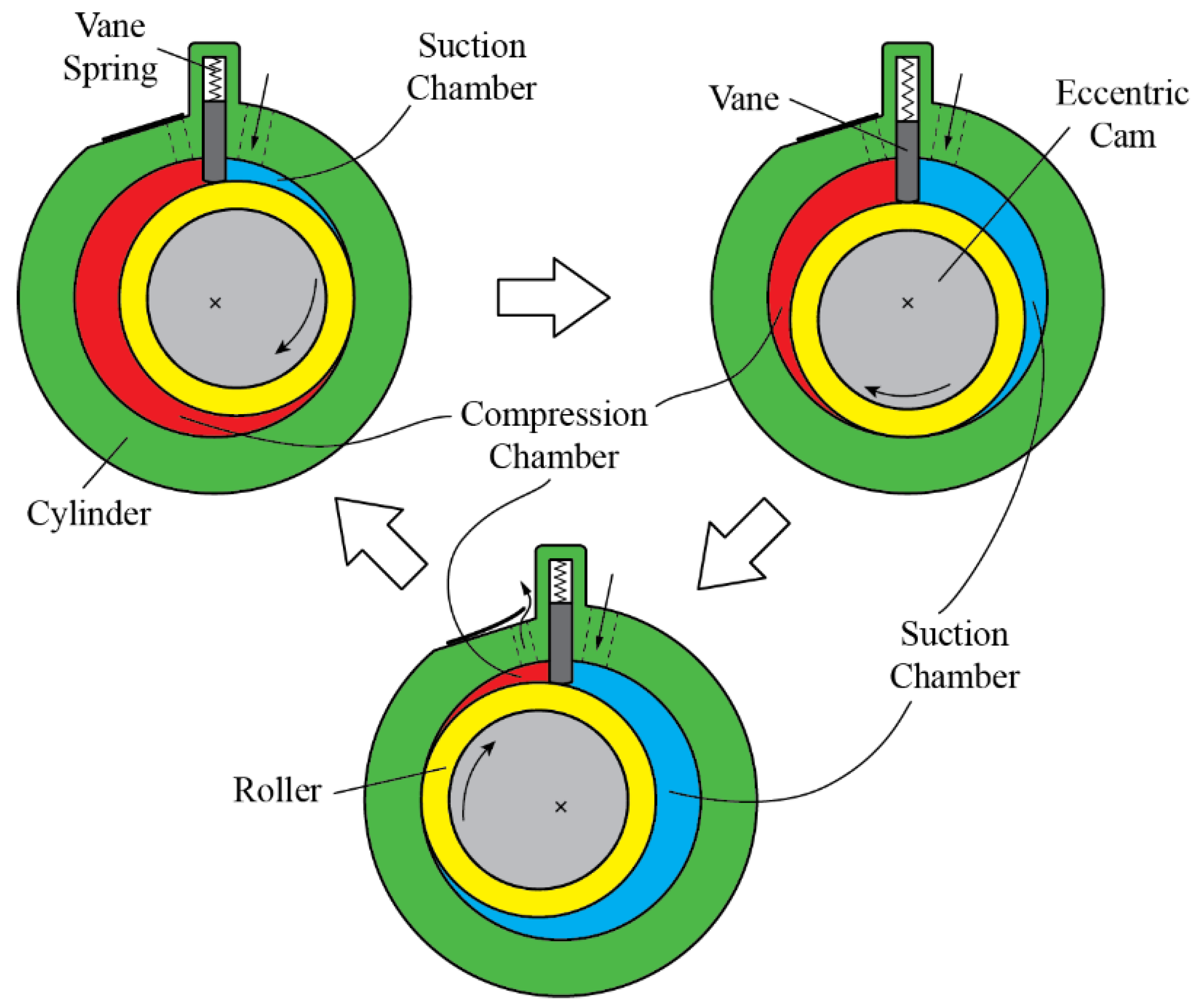
Table 1.
Vapor-compression system and rotary compressor timeline.
| Year | Description |
|---|---|
| 1834 | First vapor-compression refrigeration system was patented by Jacob Perkins that utilizes a piston compressor [1]. |
| 1856 | James Harrison achieved commercial success for his vapor-compression refrigeration system [1]. |
| 1874 | Charles Barnes patented the first rotary vane pump [5] that evolved into the sliding vane compressor. |
| 1916 | Douglas Henry Stokes invented the first hermetic compressor that utilizes the reciprocating mechanism [6]. |
| 1950 | First computational modeling pertaining to compressor research by Costagliola [7]. |
| 1960s | Commercial production of rolling piston compressors in Japan [8]. |
| 1972 | First publicly available literature on sliding vane compressor modeling [9,10]. |
| 1978 | First publicly available literature on rolling piston compressor modeling [11]. |
| 1987 | Montreal Protocol was signed to phase out chlorofluorocarbons (CFCs) to repair ozone depletion [12]; CFCs were commonly used as refrigerants then, so replacement refrigerants had to be found. |
| 1997 | The Kyoto Protocol was signed to reduce greenhouse gas emissions [13]. |
| 1998 | The Montreal Protocol now included the phase out of hydrochlorofluorocarbons (HCFCs) [12]. HCFC refrigerants were initially used to replace CFC refrigerants but later found to have extremely potent greenhouse effects. |
| 2015 | Paris Agreement was signed to reduce greenhouse gas emissions [14]. |
| 2016 | The Kigali Amendment to the Montreal Protocol was added to include the phase out of hydrofluorocarbons (HFCs) [12]. HFC refrigerants were also found to have extremely potent greenhouse effects. |
Table 2.
Sliding vane compressor performance.
| Reference (Year) | Working Fluid | Displacement per Revolution | Max. Efficiency (Type) | Remarks/Features |
|---|---|---|---|---|
| Tothero and Keeney [23] (1978) | R12 | 151 cm3 | 81% (Volumetric efficiency) | Automotive compressor |
| Maruyama et al. [26] (1982) | Air | 85.5 cm3, 94 cm3 | 85% (Volumetric efficiency) | Automotive compressor |
| Tassou and Qureshi [24] (1998) | R22 | 142 cm3 1 | 80% (Volumetric efficiency) 66% 1 (Isentropic efficiency) | Open type (non-hermetic) compressor |
| Cipollone et al. [27] (2011) | Air | 380 cm3 1 | 91.6% 1 (Mechanical efficiency) | 22 kW compressor |
1 Authors’ interpretation of the graphical plot or calculated from given data.
Table 3.
Sliding vane compressor performance with injection mechanisms.
| Reference (Year) | Working Fluid | Displacement per Revolution | Max. Efficiency (Type) | Injection Type |
|---|---|---|---|---|
| Kruse [15] (1980) | Air | – 2 | 44% 1 (Isentropic efficiency) | Oil |
| Hickman and Neal [45] (1984) | R22 | – 2 | 80% (Volumetric efficiency) | Liquid refrigerant |
| Bianchi et al. [35] (2015) | Air | 400 cm3 1 | 90.6% 1 (Mechanical efficiency) | Oil |
| Bianchi and Cipollone [42] (2015) | Air | 378 cm3 | 96.7% (Volumetric efficiency) 88.5% 1 (Mechanical efficiency) | Oil |
| Cipollone et al. [44] (2015) | Air | 400 cm3 1 | 90.7% 1 (Mechanical efficiency) | Oil atomizer spray cooling |
1 Authors’ interpretation of the graphical plot or calculated from given data. 2 Information not available in literature.
Table 4.
Performance of fixed sliding vane variants.
| Reference (Year) | Working Fluid | Displacement per Revolution | Max. Efficiency (Type) | COP | Type |
|---|---|---|---|---|---|
| Edwards [52] (1988) | R114 | 490 cm3 | 80% (Isentropic efficiency) 92% (Volumetric efficiency) | 4.85 | Controlled rotary vane mechanism |
| Smith and Harrison [51] (1992) | – 2 | 227 cm3 | 67% 1 (Isentropic efficiency) 88% 1 (Volumetric efficiency) | 4.4 1 | Groll rotary vane mechanism |
1 Authors’ interpretation of the graphical plot or calculated from given data. 2 Information not available in literature.
Table 5.
Rolling piston compressor performance.
| Reference (Year) | Working Fluid | Displacement per Revolution | Max. Efficiency (Type) | Remarks/Features |
|---|---|---|---|---|
| Chu et al. [74] (1978) | R22 | – 2 | 93% (Volumetric efficiency) | – 2 |
| Ozu and Itami [8] (1981) | – 2 | – 2 | 95% (Volumetric efficiency) 90% (Mechanical efficiency) | 7000 BTU h−1 |
| Matsuzaka and Nagatomo [75] (1982) | R22 | 9 cm3 1 | 94% (Volumetric efficiency) 94% (Mechanical efficiency) 74% (Overall efficiency) | – 2 |
| Wakabayashi et al. [76] (1982) | R22 | 10.5 cm3 1 | 93% (Mechanical efficiency) | – 2 |
| Sakaino et al. [77] (1984) | – 2 | 56.9 cm3 | 98% (Volumetric efficiency) 92% (Mechanical efficiency) | – 2 |
| Sathe et al. [78] (2008) | R134a | 1.4 cm3 | 91% (Volumetric efficiency) 70% (Isentropic efficiency) | Miniature rolling piston |
1 Authors’ interpretation of the graphical plot or calculated from given data. 2 Information not available in literature.
Table 6.
Performance of dual cylinder and two-stage rolling piston compressors.
| Reference (Year) | Working Fluid | Displacement per Revolution | Max. Efficiency (Type) | Type |
|---|---|---|---|---|
| Sakaino et al. (1986) [173] | – 2 | 80.6 cm3 | 98% (Volumetric efficiency) 92% (Mechanical efficiency) | Dual cylinder rolling piston |
| Dreiman et al. (2004) [183] | CO2 | – 2 | 80% (Volumetric efficiency) 60% (Isentropic efficiency) | Two-stage rolling piston |
| Yang et al. (2012) [184] | CO2 | 3.3 cm3 1 | 88% (Volumetric efficiency) 90% (Mechanical efficiency) | Two-stage rolling piston |
| Lee et al. (2016) [186] | R410A | 15 cm3 | 92% (Volumetric efficiency) 94% (Mechanical efficiency) | Two-stage rolling piston |
1 Authors’ interpretation of the graphical plot or calculated from given data. 2 Information not available in literature.
Table 7.
Swing mechanism compressor performance.
| Reference (Year) | Working Fluid | Displacement per Revolution | Max. Efficiency (Type) | Remarks/Features |
|---|---|---|---|---|
| Masuda et al. [222] (1996) | R134a, R407C, R410A | 12.8 cm3 | 97% 1 (Volumetric efficiency) | Swing compressor |
| Shintaku et al. [236] (2000) | R22 | 25.2 cm3 | 89% (Mechanical efficiency) 96% (Volumetric efficiency) | Variant–swivel vane fixed on roller |
| Okur et al. [237] (2011) | Air | – 2 | 90% (Isentropic efficiency) | Variant–hinged vane on roller |
| Pan et al. [234] (2019) | R410A | 10.5 cm3 | 91% (Volumetric efficiency) 79% (Isentropic efficiency) | Valve-less swing compressor |
| Lim and Ooi [241] (2020) | Air | 24 cm3 1 | 92% (Volumetric efficiency) | Variant–U-vane swing compressor |
1 Authors’ interpretation of the graphical plot or calculated from given data. 2 Information not available in literature.
Table 8.
Synchronal rotary/revolving vane compressor performance.
| Reference (Year) | Working Fluid | Displacement per Revolution | Max. Efficiency (Type) | Remarks/Features |
|---|---|---|---|---|
| Teh and Ooi [248] (2009) | Air | 32.5 cm3, 34.6 cm3 | 81% 1 (Volumetric efficiency) | Swivel vane design |
| Tan and Ooi [260] (2014) | Air | 1.7 cm3 1 | 26% (Mechanical efficiency) | Fixed vane design |
| Aw and Ooi [253] (2021) | Air | 50 cm3 | 45% (Volumetric efficiency) 1% (Isentropic efficiency) | Oil-free, fixed vane design |
1 Authors’ interpretation of the graphical plot or calculated from given data.
Publisher’s Note: MDPI stays neutral with regard to jurisdictional claims in published maps and institutional affiliations. |
© 2021 by the authors. Licensee MDPI, Basel, Switzerland. This article is an open access article distributed under the terms and conditions of the Creative Commons Attribution (CC BY) license (https://creativecommons.org/licenses/by/4.0/).
Share and Cite
MDPI and ACS Style
Aw, K.T.; Ooi, K.T. A Review on Sliding Vane and Rolling Piston Compressors. Machines 2021, 9, 125. https://doi.org/10.3390/machines9060125
AMA Style
Aw KT, Ooi KT. A Review on Sliding Vane and Rolling Piston Compressors. Machines. 2021; 9(6):125. https://doi.org/10.3390/machines9060125
Chicago/Turabian StyleAw, Kuan Thai, and Kim Tiow Ooi. 2021. "A Review on Sliding Vane and Rolling Piston Compressors" Machines 9, no. 6: 125. https://doi.org/10.3390/machines9060125
Note that from the first issue of 2016, this journal uses article numbers instead of page numbers. See further details here.