1. Introduction
The ankle joint is critical to locomotion by sustaining the load of the whole body while exerting key forces during push-off, leg swing, and center of mass advancement during the human gait [
1]. Unfortunately, it is also one of the most commonly injured joints of the human body, often subject to sprains or fractures that hinder or impede a full walking capability of a patient [
2]. In order to recover full mobility, rehabilitation and motion assistance are required [
3]. Rehabilitation training is usually performed by a physiotherapist in one-on-one sessions with a patient because it requires the physiotherapist’s full attention.
Robot-assisted rehabilitation was proposed as an efficient alternative, since it would enable a single physiotherapist to assist multiple patients at the same time, potentially teleoperating the robots from a remote location. The feasibility of a robotic solution for the assistance of patients in the recovery of gait functions has been proved by several research groups [
4,
5,
6,
7]. However, most of the ankle rehabilitation robots are based on static platform designs, as illustrated in [
8,
9,
10,
11,
12,
13,
14,
15,
16]. In the work in [
8], rehabilitation is performed with the patient standing on two platforms with variable orientation. This solution requires the patient to be able to stand up, and it is characterized by a bulky (non-portable) device. Another grounded design is proposed in [
9] for the rehabilitative exercise of a single leg, which is similar to the prototype in [
10] with a mechanism driven by pneumatic muscles. An evolution of the same design is reported in [
11]. Smaller but still grounded devices are introduced in [
12] and [
13] as based on a high-performance parallel architecture and a compliant mechanism, respectively.
All these robots are characterized by static designs, and most of them, such as the prototypes in [
14,
15,
16], are fixed to the ground or are difficult to move due to a large footprint and weight. In order to overcome this limit, few research groups have proposed wearable designs such as ankle exoskeletons and orthoses [
3,
17]. These wearable rehabilitation systems are usually characterized by rigid or compliant links and bulky bodies, thus still requiring additional support for their significant weight.
Cable-driven robots may solve all these issues thanks to their lightweight structures. Additionally, they can be safer than conventional mechanisms thanks to their negligible moving mass [
18]. Portable cable-driven rehabilitation robots have already been introduced in [
18,
19,
20] for legs and elbows. In fact, cable-driven parallel mechanisms have recently attracted attention even in specific applications, as reported in the dedicated conference series in [
21], where nevertheless the topic of ankle assistance devices is not analyzed. Only a few research groups have proposed static (non-portable) designs for ankle rehabilitation [
22,
23]. In particular, the work in [
22] studies the feasibility of cable-driven ankle rehabilitation without proposing a specific design. A grounded platform is described in [
23], but its four cables are not enough to enable full control of the ankle joint, since the proposed device is fixed to the foot but not to the shank of the patient. While three degrees of freedom is enough to control the foot motion with respect to the leg, grounded designs require either more degrees of freedom or additional constraints to the leg. According to the authors’ knowledge, there is no portable cable-driven solution available for ankle motion assistance.
The CABLEankle is presented in this paper as a lightweight wearable robot for ankle motion assistance with a cable-driven architecture. The CABLEankle is inspired by the CADEL architecture first presented in [
20], which can be modeled as a cable-driven S-4S
PS parallel mechanism. The original elbow rehabilitation mechanism is adapted to the new geometric and motion requirements for ankles. In [
24], the conceptual design of the CABLEankle is briefly introduced with its kinematic model and a numeric simulation for a limited two-degree-of-freedom motion range. This manuscript expands the research work of [
24] with a detailed kinematic and static analysis that includes a novel formulation for the force-closure model of the proposed cable-driven mechanism. Furthermore, a numerical simulation is included to validate the feasibility of the CABLEankle for the full ankle mobility range, in order to characterize the performance of this novel design in terms of motion range, cable tension, load on the ankle joint, and motor power.
2. Materials and Methods
In this section, the design process of the proposed ankle rehabilitation device is reported with the main methods used to synthesize and analyze the mechanism. First, motion requirements are defined by studying the biomechanics of the human ankle joint, with a focus on its mobility. Then, the conceptual design of the mechanism is introduced with its main characteristics. A closed-form analytical solution is provided for the kinematics of the proposed device, which is needed to actuate and control the ankle motion. A static model is then reported to evaluate cable tension and ankle joint reaction forces during motion. Finally, a novel formulation for force-closure of cable-driven mechanisms is also presented in this paper to validate the feasibility and the performance of the device in its workspace.
2.1. Motion Requirements from Ankle Biomechanics
The ankle joint complex connects the lower leg and the foot, and it is made up of three main joints, namely the talocalcaneal, tibiotalar, and transverse-tarsal joint. It can sustain large compressive and shear forces while keeping a high degree of stability during gait [
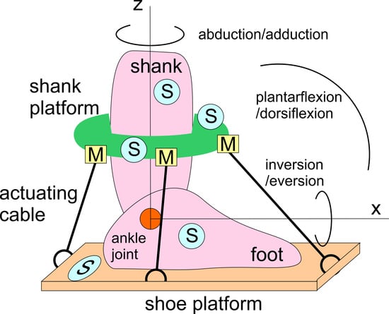
25]. The complex mobility of the ankle can be approximated by its three main motion modes, which are illustrated in
Figure 1: plantarflexion and dorsiflexion, in the sagittal plane; abduction and adduction, in the transverse plane; inversion and eversion, in the frontal plane.
The ranges of motion of these modes are characterized by a significant variability between individuals, due to geographical/cultural differences, anatomical structures, and distinct data-acquisition methodologies. In order to define a target range of motion for an ankle-assisting device, conservative values for the ankle range of motion as per
Figure 1 have been extracted from [
25,
26,
27], as summarized in
Table 1 referring to daily activities.
Design requirements may refer to healthy ranges of motion as in
Table 1, but for motion assistance smaller ranges can be considered mainly in application for rehabilitant therapies and elderly people assistance. In addition to the kinematic aspects of the range of motion, requirements for design and operation purposes can be considered in terms of actions on the ankle to achieve a desired ankle movement either in full passive mode or with a user participation that can be controlled and guided. This action can be sized within a range of 1 to 20 N when considering unloaded ankle motion in the air and can be scaled up to more than 100 N if users stand up on the foot. In general, however, a rehabilitation therapy can be planned with a leg in the air. Therefore, the force requirements for the device developments can be assumed as less than 30 N, considering also possible exercise training to reinforce the ankle muscular system.
2.2. Conceptual Design of a Wearable Device for Ankle Motion Assistance
Figure 2a shows a conceptual design of CABLEankle, a wearable device for ankle motion assistance. The above-mentioned issues are addressed with the indication of motion directions and with a scheme of a cable-driven system that is equipped also with suitable sensors (S) for monitoring and controlling purposes. The application of the device can range from motion guidance, as per exercise and augmentation of ankle capacity, to motion assistance, as per rehabilitation and physiatry ankle medical therapy.
The motion of the ankle with respect to the shank (part of a person’s leg between the knee and the ankle) is planned by the relative motion of a foot platform, which can even include a shoe for wearing the system, with respect to a shank platform, which can be ring-shaped to be worn on the shank. The motors (M) increase or decrease cable lengths to guide this relative motion with a mechanical structure that is equipped of a pulley and servomotor. The control system can use information from sensors (S), which can be both on board of the device and worn by the patient. These sensors can include accelerometers and IMUs, which enable gait analysis as reported, for example, in [
28]. Sensors (S) can be used not only for operation control of the device, but also for monitoring of ankle medical issues, such as for measures of temperature, muscle reaction and blood pressure, as required in the device application.
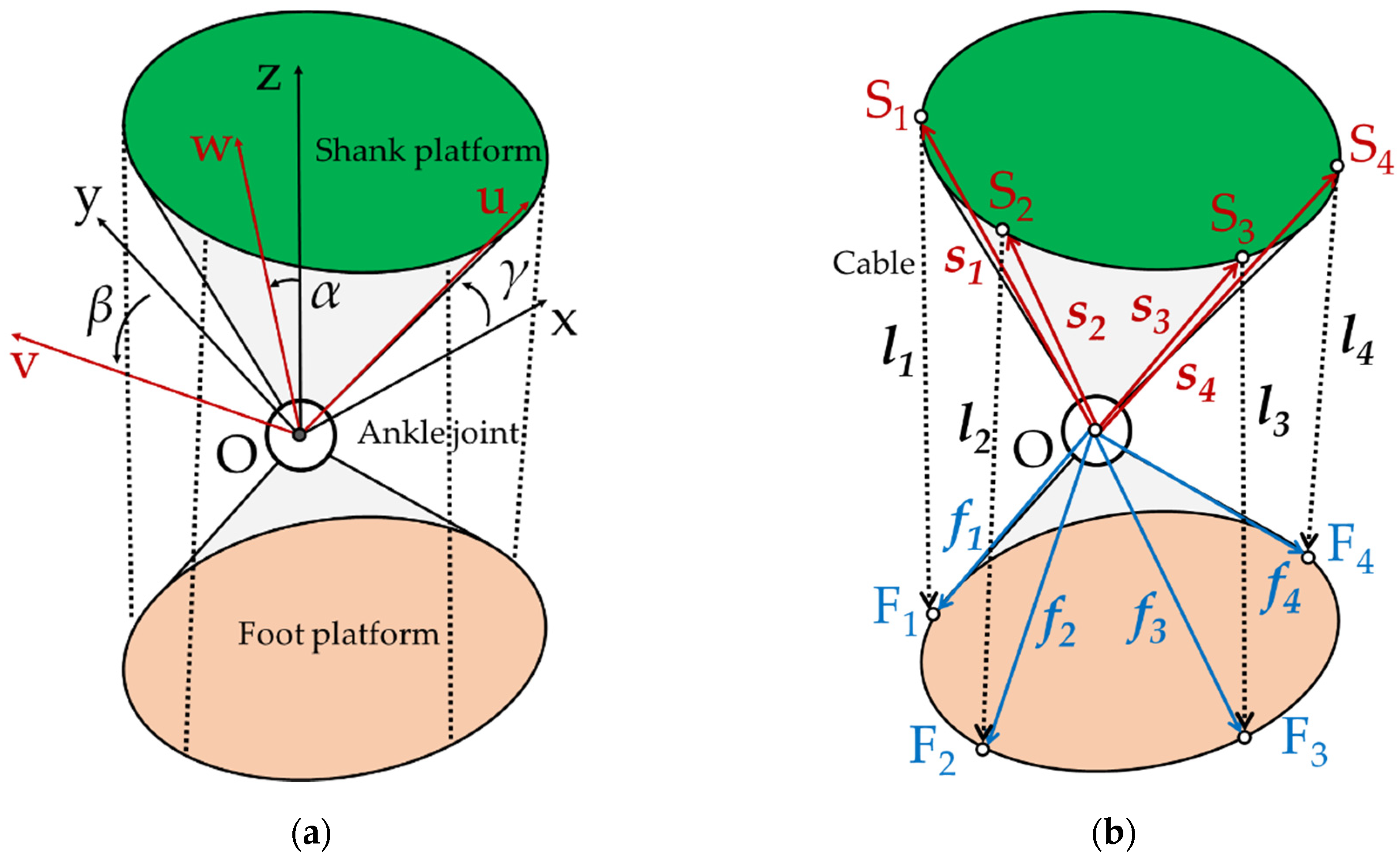
Figure 2b shows a CAD design of a mechanical solution, highlighting the lightweight compact features of the conceptual design for portability and user-oriented operation. A power supply can also be integrated inside the foot platform, on the shank platform or in a box nearby the device.
2.3. Kinematic Analysis
The proposed solution in
Figure 2 is a cable-driven parallel mechanism that is inspired by the CADEL design for elbow rehabilitation in [
20]. The device is characterized by a foot platform and a shank platform that are connected by four cables of varying length, as shown in the models of
Figure 2. The two platforms are connected to the foot and the shank of the patient, respectively, by means of straps or equivalent comfortable means, and both of them can be assumed to be fixed to a patient’s leg and foot. Thus, by varying the length of the cables, it is possible to activate a relative motion between foot and shank, guiding the patient’s ankle motion. The kinematic behavior of the ankle motion can be approximated by a spherical joint with limited angular motion. Therefore, it is possible to model the proposed solution as a lower-mobility parallel mechanism with three degrees of freedom, by using a S-4S
PS architecture, as shown in the model of
Figure 3.
The reference frame S of the shank platform is Oxyz, whereas the reference frame F of the foot platform is Ouvw, as in
Figure 3a. A general relative motion of the ankle joint can be described by three consecutive rotations around different axes. Thus, by considering an intrinsic roll–pitch–yaw rotation, the orientation of the foot platform with respect to the shank platform can be expressed as
. In
Figure 3b the
ith cable’s upper extremity is attached to point S
i of the shank platform, and its lower extremity is attached to the corresponding point F
i of the foot platform. The following hypotheses are assumed:
All the cables are always kept in tension during a controlled motion;
The attachment point of each cable behaves as a spherical joint;
The varying length of the cable can be modeled as an actuated prismatic joint cable-link with a negligible axial deformation, that can be ensured by a proper cross-section size, material choice (e.g., Dyneema cables), and thanks to the short length of the cables in the proposed application.
The position of the
ith cable attachment is
for the shank platform and
for the foot platform. The ankle pose can be described as
, where
α,
β and
γ are the intrinsic rotations around the
z-,
y- and
x-axis, as previously defined. The actuation is expressed by
, where
li is the distance between points S
i and F
i of each cable, computed as the magnitude of vectors
li in
Figure 3. Vectorial loop-closure equations can be written for each cable as
The cable length vector can be computed from (1) as
Then, by computing the scalar product of each side of (2) by itself, the length of each cable can be expressed as
As reported in
Appendix A, the input–output relation can be obtained by deriving Equation (2), as
where the
ith cable unit vector is defined as
ui.
2.4. Static Analysis
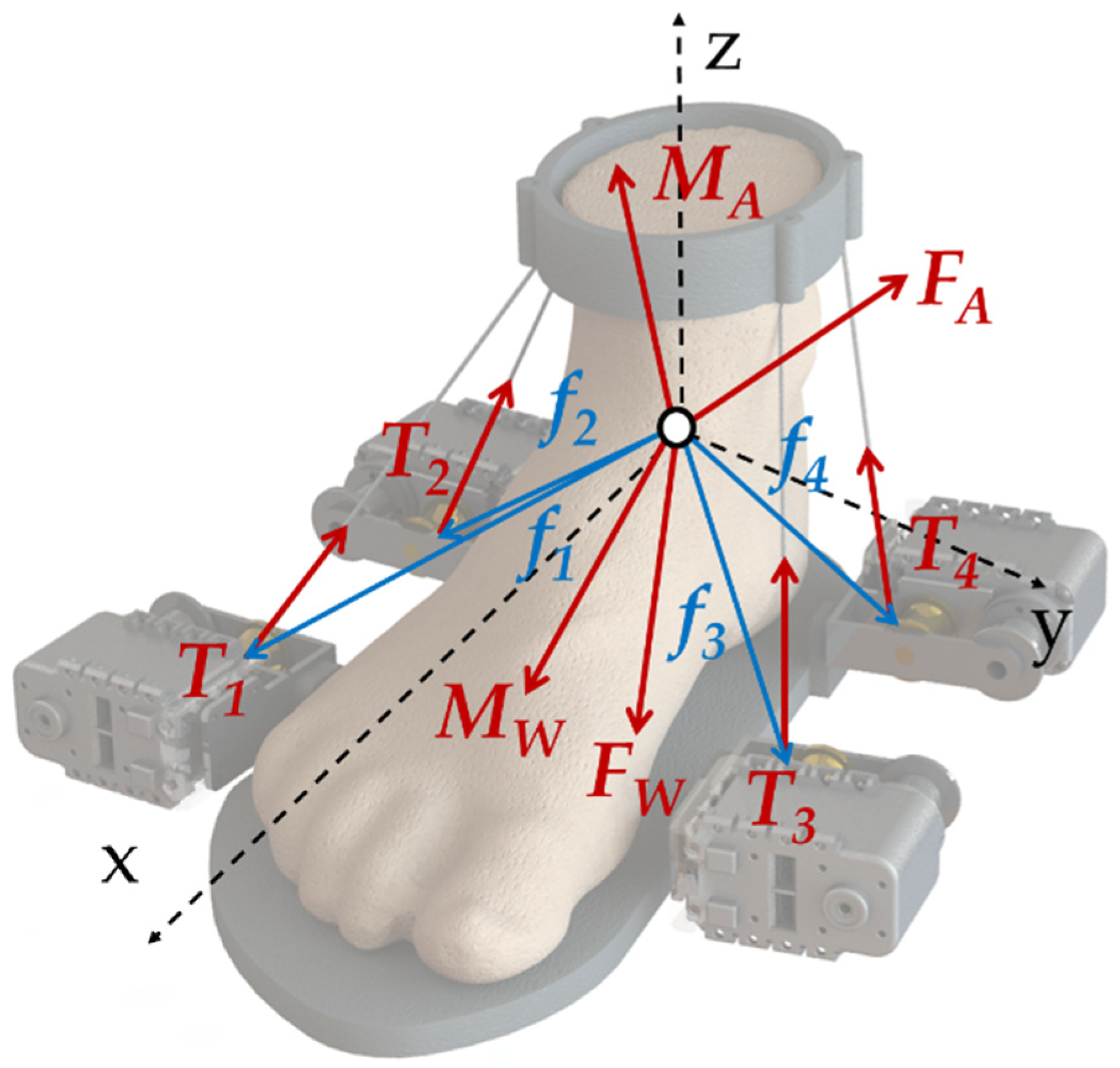
In both rehabilitation and assistance scenarios, the proposed device guides the assisted ankle with a controlled smooth motion, in order to avoid stress, pain or damage to a wearer. Because of the negligible moving mass and the slow speed motion, dynamics and inertial effects can be neglected, and performance evaluation can be computed by using a static model as proposed in the following. When a generic wrench, which can be defined as force
FW and moment
MW, is applied to the foot platform, a static equilibrium can be achieved with a combination of the reaction at the ankle joint, in terms of reaction force
FA and reaction moment
MA, and of cable tension
T, as in the scheme in
Figure 4.
Thus, the equilibrium condition to translation in reference frame S is given by
where
Ti is the tension in the
ith cable, whereas the equilibrium condition to rotation is given by
By defining cable unit vector
ui, the tension in the
ith cable can be expressed as the product of its magnitude and limb unit vectors
ui as
. The actuation vector
T, with components
, can be used to rewrite Equations (5) and (6) to get
and the equilibrium condition to rotation can be written as
with
and
.
Since the ankle joint has been approximated as a spherical joint, it can constrain translational motion only, while reaction moment
MA is a null vector within the ankle motion range. Therefore, the full equilibrium condition can be given by
2.5. Force Closure
Unlike rigid links, cables can pull the two bodies together but cannot push. Thus, the results obtained from the kinematics in Equations (3) and (4) and from the static model in Equation (9) cannot be directly applied to a real system. Therefore, the poses where the moving platform is fully constrained by the cables must be determined maintaining positive cable tension as critical condition in constraining the moving platform. Hence, the force-closure workspace is a set of poses whereby resultant cable tensions can sustain an arbitrary external wrench acting on the moving platform, as pointed out in [
29].
A general cable-driven parallel mechanism is said to have a force closure in a given pose if and only if any arbitrary external wrench applied at the moving platform can be sustained through appropriate positive tension forces in the cables [
30,
31]. The condition for force closure is usually described as
A mathematical solution for a standard cable-driven parallel mechanism is well established in scientific literature for the case of
n-DoF manipulator with
n + 1 cables as reported, for example, in [
29,
30,
31,
32], but the mechanism under analysis has a hybrid structure with the ankle joint in parallel with the cables. Therefore, a different approach is needed. Without any rigid joint, the force closure would be verified for any of the following conditions:
The columns of positively span ;
The convex hull of the column of contains the neighborhood of the origin;
There does not exist a vector , such as that the scalar product of and each column of is greater than or equal to 0.
However, the ankle joint is not modeled by those conditions, and it is therefore assumed that the cables must balance any wrench without the contribution of the joint reaction force (which can both pull and push, differently from the cables). Thus, verifying force closure with those conditions would impose unneeded design constraints by not considering the action of the ankle/leg.
Since the two platforms are connected by the ankle joint, the components of the wrench relative to the degrees of freedom that are constrained by the joint can be fully balanced by the reaction of the joint itself, while the cables are used to balance only the reaction moments relative to the idle rotational degrees of freedom. Therefore, the proposed motion assistance device can be said to have force closure in a given pose if and only if any arbitrary external wrench, which is applied at the moving platform and it cannot be balanced by the ankle joint, can be sustained through appropriate (positive) tension forces in the cables. This definition of force closure can be mathematically expressed as
Therefore, force closure can be verified by any of the following conditions:
The columns of positively span ;
The convex hull of the column of contains the neighborhood of the origin;
There does not exist a vector , such as that the scalar product of and each column of is greater than or equal to 0.
This novel definition of force closure drastically simplifies the solution for a cable-driven rotational joint. A simple example is here reported for a 2D dorsiflexion-plantarflexion motion that is characterized by the simplified geometry in
Figure 5. In this example, three possible positions are defined for the cables that will drive the rotation of the ankle around the
Y-axis, defined by cable attachment points S
1F
1, S
2F
2 and S
3F
3, respectively. The main parameters of the example are defined in
Table 2.
When considering a planar motion, the ankle joint has all translational degrees of freedom, thus allowing only the rotation around the
y-axis. The other rotational degrees of freedom are out of the considered plane and therefore neglected in this example. Three possible combinations of cables are considered to drive the revolute joint, as shown in
Table 3. When using Equation (11), the elements of matrix
related to the rotation around the
x-axis and the
z-axis can be ignored, and by applying the second condition to verify force closure, it is possible to see that the 1D convex hull of the columns of the 1 + 2 case does not contain the neighborhood of the origin, while all the other options satisfy the condition. From a physical point of view, it can be noticed that to drive a rigid joint at least a cable on each side is needed to force rotation in both senses. While combinations 1 + 3 and 2 + 3 easily satisfy this condition, combination 1 + 2 cannot, as proved by the example. This calculation can be easily expanded and implemented for the 3D case (yielding a 3 × N matrix
, with N > 3, and a convex hull defined by N points in a 3D space).
3. Results
By using the models developed in
Section 2, a target ankle motion can be achieved thanks to the Inverse Kinematic formulation in Equations (3) and (4), whereas the static model in (9) and the force closure condition in (11) can be used as the base for a predictive force control to avoid the wearer from getting injured by excessive ankle load from the proposed CABLEankle operation. In addition, the above kinematics and force analysis can characterize the proposed design in terms of operation performance for a practical implementation of a prototype in a near-future development.
Therefore, the proposed CABLEankle design can be validated on the average motion range of the human ankle, by evaluating its performance on the three motion modes of the ankle, namely dorsiflexion/plantarflexion, inversion/eversion, and adduction/abduction, as illustrated in
Figure 1 and with the numerical limits in
Table 1. Each motion mode simulates a rotation from the lower to the upper limit of the ankle joint.
3.1. Kinematics
The design configuration of the device in
Figure 2, for which patent data are given in in [
33], is characterized by the geometry in
Table 4 with the results of simulated operation in terms of elongation of the actuation cables, tension in the actuation cables, and load on the ankle joint, as in
Figure 6,
Figure 7 and
Figure 8, respectively. In the tested operations, each cable has a minimum length of 20 mm and a maximum length of 200 mm. By using the Inverse Kinematic formulation in Equation (3), it is possible to compute the length of each cable for the simulated motion modes with the results that are illustrated in
Figure 6.
3.2. Statics and Force Closure
The static model of Equation (9) can be used to evaluate both the ankle joint reaction and the tension in the cables. The simulation results have been computed by assuming no external wrench applied onto the foot except for its own weight, with an estimated mass of 1.00 kg as per an exercise of the ankle on the air. The resulting values of cable tension for the simulated motion modes are reported in
Figure 7, whereas the load on the wearer’s ankle is shown in
Figure 8.
The entire motion range of the ankle, as expressed in
Table 1, is included in the force closure workspace of the proposed cable-driven parallel robot, which is evaluated with the proposed formulation in Equation (11). This condition is essential to ensure that the motion of the ankle can be controlled by the cable-driven mechanism and that no unexpected/uncontrolled motion is allowed.
3.3. Power Consumption
By using the simulated motion data, it is also possible to compute the ideal power consumption of the system by assuming negligible losses due to friction and other external factors. For each simulated motion, the total time has been assumed equal to 5.0 s, representing a slow motion from the minimum to the maximum angle for rehabilitation purposes. The instantaneous power consumption
of the
ith motor can be estimated as
where
is the motor torque, which can be computed by multiplying the tension in the
ith cable and the driving pulley diameter, and
is the angular velocity of the ith motor, which can be computed from the variation rate of the
ith cable
, from vector
in Equation (4).
For the simulated motion modes, the overall power consumption of the four actuators in the system is characterized by a maximum value of 20 W when the mechanism moves in the upper limit of its motion range in the inversion/eversion and adduction/abduction motion modes.
4. Discussion
The results in
Figure 6 demonstrate that the proposed CABLEankle design can operate in the full range of motion of the ankle without reaching joint or device limits. with suitable smooth motion and limited variation of the cable lengths. The largest variation of cable length is computed as 46 mm for cable 1 in
Figure 6a and the smallest one is of 5 mm for cable 3 in
Figure 6b.
The values of cable tension that are computed with the proposed static analysis for the simulated motion modes in
Figure 7 have a maximum value of 90 N. Thus, they are safely within the maximum value that is allowed by a rotational motor driving the cable. Another key result from the static analysis is the load on the wearer’s ankle, as shown in
Figure 8. The force acting on the ankle is reported in terms of its cartesian components to emphasize the influence of motion direction, with the component along the x-axis of the foot as per
Figure 1 being the most significant one, whereas the vertical component along the z-axis shows the largest variability. During the simulated motion, the load reaches a maximum with 60 N, which is well sustainable with a healthy ankle but could be dangerous in the case of rehabilitation of an injured one. In that case of rehabilitation exercise, the inversion/eversion and abduction/adduction motions should be limited to a range less than 10 deg with a suitable ankle load smaller than 30 N. With such a practical range of assisted motion, the tension in the cables are reduced conveniently up to much less than the computed maximum of 90 N.
The low power consumption of the prototype means that the proposed device can be powered by portable batteries. A 10,000 mAh battery, for example, can guarantee up to two hours of continuous functioning, thus removing the need for an external power supply. A power supply with commercial batteries can be integrated in the foot platform, on the shank platform or in a box nearby the device. Thus, the device can include the battery, the motors, a small control board and a Bluetooth module, removing the need for complicated electrical wire routing between different bodies of the robot. A portable battery, combined with an estimated weight of 2.0 kg (of which 0.7 kg of prototype and 1.3 kg of battery), makes the proposed design truly lightweight, portable, and user-friendly.


