1. Introduction
The field of predictive maintenance of electric machines has become a strategic concept in all industrial production processes. Machine monitoring makes it possible to precisely diagnose potential faults to quickly act before breakage. Electric energy converters, in particular permanent magnet synchronous machines (PMSMs), are occupying an increasingly important place in industrial equipment, electric traction (electric vehicles, ships, etc.), and power conversion in renewable energy (wind turbine, alternators, etc.) due to their high efficiency, ease of manufacture, and high power and torque density [
1,
2,
3,
4]. The sensitivity of PMs to an operating temperature, their high cost, and probable demagnetization issue requires the implementation of an appropriate diagnostic technique to describe the behavior of the machine in the presence of the fault and thus characterize the demagnetization influence.
PMs are the most costly part of PMSMs [
5]. They are able to easily lose their quality under several difficult running conditions giving rise to the demagnetization fault (DMF). It can be characterized as the loss of the ability to produce magnetic flux. Demagnetization can be either uniform or partial. In a uniform demagnetization case, all magnets are uniformly affected at the same time, but for a partial demagnetization only a set of magnets is impacted by the defect.
Electrical faults, mechanical stresses, thermal and environmental conditions can damage the PMs, and generate their demagnetization [
6]. An armature reaction generated by the large temperatures and high currents caused by aging, physical damage, and short-circuit causes the demagnetization fault. The physical damage and the armature reaction generally induce partial demagnetization faults and aging commonly gives rise to uniform defects.
The first effect of such fault would be the deformation of the resulting magnetic flux density in the airgap. This flux perturbation gives rise to current harmonics and unbalanced magnetic pull (UMP), which creates acoustic noise. Moreover, the electromotive force (EMF) magnitude in the stator windings will be disturbed. In some incidents, broken pieces of PMs falling in the airgap may deteriorate the winding of the stator [
6]. Thus, defect detection, at an early stage of growth, is important for PMSMs and leads to the prevention of huge maintenance costs [
7].
Many studies have attempted to detect demagnetized magnets. There are countless papers in the literature dealing with the issue of PMs DMF diagnosis in PMSMs. A comprehensive analysis of these fault diagnosis techniques can be found in [
2,
8,
9,
10,
11,
12]. Commonly used motor fault diagnosis methods can be divided into: Model-based and signal-based fault diagnosis methods. A model-based fault diagnosis is based on residual generation by creating a motor model containing a certain fault based on physical principles [
13]. Specifically, it is based on comparing the model predicted output with the actual measured output to determine whether the fault has occurred in the motor. Contrary wise, signal-based approaches require signal processing methods [
14]. It is based on the physical quantities measurement on the actual system (vibration, currents, power, noise, etc.) and then extracting the faults signature using signal processing techniques. This paper is focusing on signal-based methods. Specifically, the stator currents are used as a medium for magnets faults detection and characterization, which can be used both for online and offline condition monitoring.
In this regard, researchers from the industry and academia have investigated the demagnetization fault for the purpose of ensuring a more fast and accurate diagnosis. For example, to detect a partial demagnetization fault in PMSM operating under non-stationary conditions, Wang et al. [
15] presented a novel approach using the Vold-Kalman filter (VKF-OT) based on stator current tracking characteristic orders. The envelope amplitude of the fault characteristic orders is used as a fault indicator. Moreover, authors in [
16] performed the VKF-OT and dynamic Bayesian network (DBN) on the torque ripple signal to detect rotor demagnetization. In [
17], the Hilbert-Huang transform (HHT) technique is considered to detect DMF in PMSM by analyzing the voltage signal of a search coil. Other works calculated the varying inductances of PMSM combined with the least square (LS) method to detect DMF [
18]. In [
19], the 1D conventional neural network (1D CNN) on the three phase current signals is adopted in the interior PMSM to diagnose inter-turns short-circuit (ISCF) and DMF even when the two faults occur simultaneously. Furthermore, in [
20], a method based on controlling the magnitude and the current angle has been proposed to detect and differentiate between DMF and ISCF. To detect and separate three different faults in PMSM; DMF, ISCF, and static eccentricity (SE), the presented work in [
21] proposed a method based on using the controlled d- and q-axes voltages changes. Authors in [
22] suggested the cogging torque analysis method to detect uniform demagnetization. This method has generated a proper fault diagnosis index, which can efficiently detect the defect. The carried-out work in [
23] presented an analytical model of the DMF single-coil no-load EMF for PMSM. The method can not only carry out the detection and evaluation of the degree of DMF but also the recognition of the demagnetization mode and the positioning of the magnetic demagnetization pole. Low levels of DMF can be detected also in [
24] by the vibration characteristics method. Xuewei et al. focused in [
25] on the local demagnetization fault of permanent magnet synchronous linear motors (PMSLMs) and carried out the accurate identification of the position and degree of faulty PMs. A fault identification process using the S-transform (ST) and particle swarm optimization–least squares support vector machine (PSO–LSSVM) is considered. The ST produces the induced EMF signal with a higher signal characteristic expression efficiency, and the PSO-LSSVM model realizes a stronger generalization capacity and greater precision in the small sample state of PMSLM faults. Experimental results prove that the method can accurately identify the PMSLM faults with a 100% recognition rate. In [
26], the authors proposed a robust and efficient technique named the second-order sliding mode control strategy for tidal turbine resilience under magnet faults.
A new method for DMF recognition and classification in double-side permanent magnet synchronous linear motors (DPMSLMs) is studied in [
27]. This technique is based on the time–time-transform (TT) to conduct a magnetic signal waveform transformation, and on the extreme learning machine (ELM) as a classifier to represent the DMF position, side, and severity types in detail. The effectiveness of the proposed method is verified with a prototype motor in an experimental platform.
From the discussion addressed above, an effective, non-invasive, and fast fault diagnosis technique is highly required, which may allow the preventive maintenance for the drive system of the PMSM. It is admitted that diagnosis methods based on electrical variables such as resultant magnetic flux, torque, voltage, and current are commonly applied in PMSMs.
One of the most commonly used methods to detect PM defects is the motor current signal analysis (MCSA). It is a well proven technique for the detection of mechanical and electrical faults in PMSM. The appearance of stator current components or the increase in the amplitude of some components at characteristic frequencies expresses a motor fault condition [
28]. They are performed by applying fast Fourier transform (FFT) to the stator current signal to extract the signal spectrum. In a faulty case, some harmonics show up in the spectrum, which are useful to detect DMF [
28]. Numerous researches have tried to detect and diagnose DMF using MCSA based on fast Fourier transform (FFT) [
29]. This technique is also proposed in [
30] to detect a 25% partial demagnetization fault in the interior permanent magnet generator.
Much of the current researches on PM defect detection adopting MCSA focus on the study of distinct and specific cases of demagnetization. Nevertheless, there is a demand for better understanding of how the current signal spectral patterns produced by particular PM fault scenarios diverge, and if this could be applied to efficiently recognize several PM fault types to improve the reliability of the fault detection method.
This paper presents a study using a finite element analysis (FEA) model of a PMSM operating under healthy conditions and with a PM DMF. A set of PM uniform and local demagnetization fault cases at various severity conditions are investigated. The paper’s purpose is to extract the spectral signature patterns generated in the signal of the stator current in faulty cases. The focus is made on a three-phase surface-mounted PMSM, and MCSA has been chosen as the demagnetization fault detection technique. The remaining parts of the paper are organized as follows. The modeling and analysis of magnet defects under different scenarios are presented in
Section 2. Then, using FEM, the resulting airgap magnetic flux density, flux linkage, stator currents, and EMFs are studied under both a uniform and partial demagnetization fault in
Section 3.
Section 4 is dedicated to present the current spectrum under a healthy and faulty PMSM. The obtained results are evaluated and compared to fulfill an effective procedure to detect, when possible, each of the different demagnetization fault scenarios.
Section 5 concludes this paper.
2. Modeling and Analysis of Magnets Defect Signature
Permanent magnets demagnetization in PMSM is treated as a critical phenomenon in which a magnet loses its ability to generate a magnetic flux partially or totally [
22,
31]. Several factors can be responsible for the magnets defect such as excessive MMF and a high operating temperature.
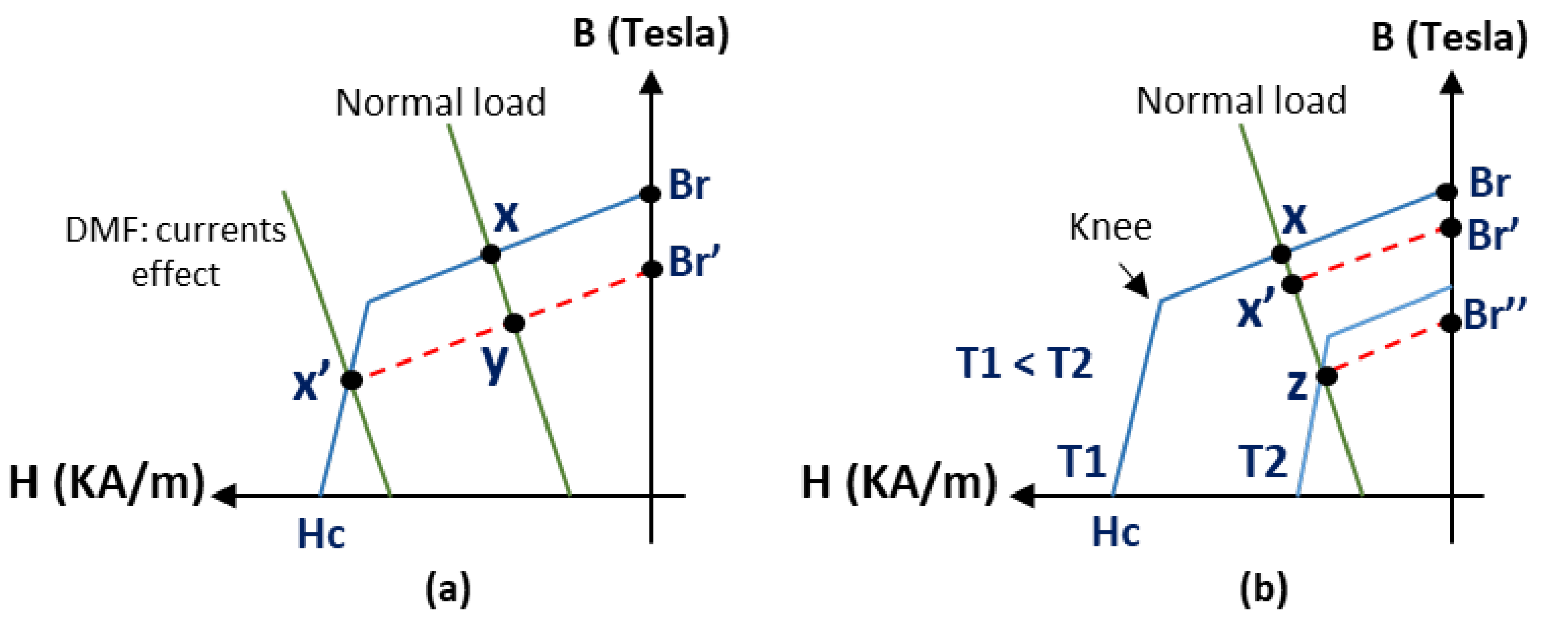
The magnet operates at the intersection between PM demagnetization curve (second quadrant of the B–H curve) and the load line as shown in
Figure 1. The motor operates at point (x) in
Figure 1a under normal load conditions. However, the operating point may be driven below the knee of the curve due to large armature currents, which produces a demagnetizing magnetomotive force (MMF). Once the operating point is brought to (x′), it does not recover its original magnetization once the demagnetizing MMF is removed. It follows the relative recoil permeability line, which is the red dotted line (line x′-y-B
r′) of
Figure 1a and recovers at point (y) under normal load conditions, causing an irreversible demagnetization. Faults in the inverter or motor due to open, short-circuited switches, phases, or a failure of the stator winding insulation can increase considerably the demagnetizing MMF and lead to a PM irreversible demagnetization [
8]. Consequently, the armature current must be limited to avoid an irreversible demagnetization.
The operating point can also fall from the knee of the curve under normal conditions with a change in the operating temperature, resulting in an irreversible demagnetization. If the magnet is exposed for a long period of time to a high temperature, it can be permanently demagnetized due to changes in the metallurgical structure that affect its ability to be re-magnetized. However, if the magnet temperature exceeds the material Curie temperature, the magnetization is reduced to zero. In this case, the material can be re-magnetized if the metallurgical structure has not been affected. The residual flux density
Br and the coercivity
Hc generally decrease with an increase in temperature for the NdFeB magnets. The offset of the demagnetization curve of an NdFeB magnet is illustrated in
Figure 1b, when it operates at a high temperature. It can be seen that the operating point (x) falls from the knee of the curve at point (z) under normal load conditions at a high temperature T2. In this condition, the operating point is formed on the red recoil line which connects (z) and B
r″, and not on the (B–H) curve, as in the previous case. If the temperature drops to T1, the operating point is formed on the recoil line (x′-B
r′), resulting in an irreversible demagnetization.
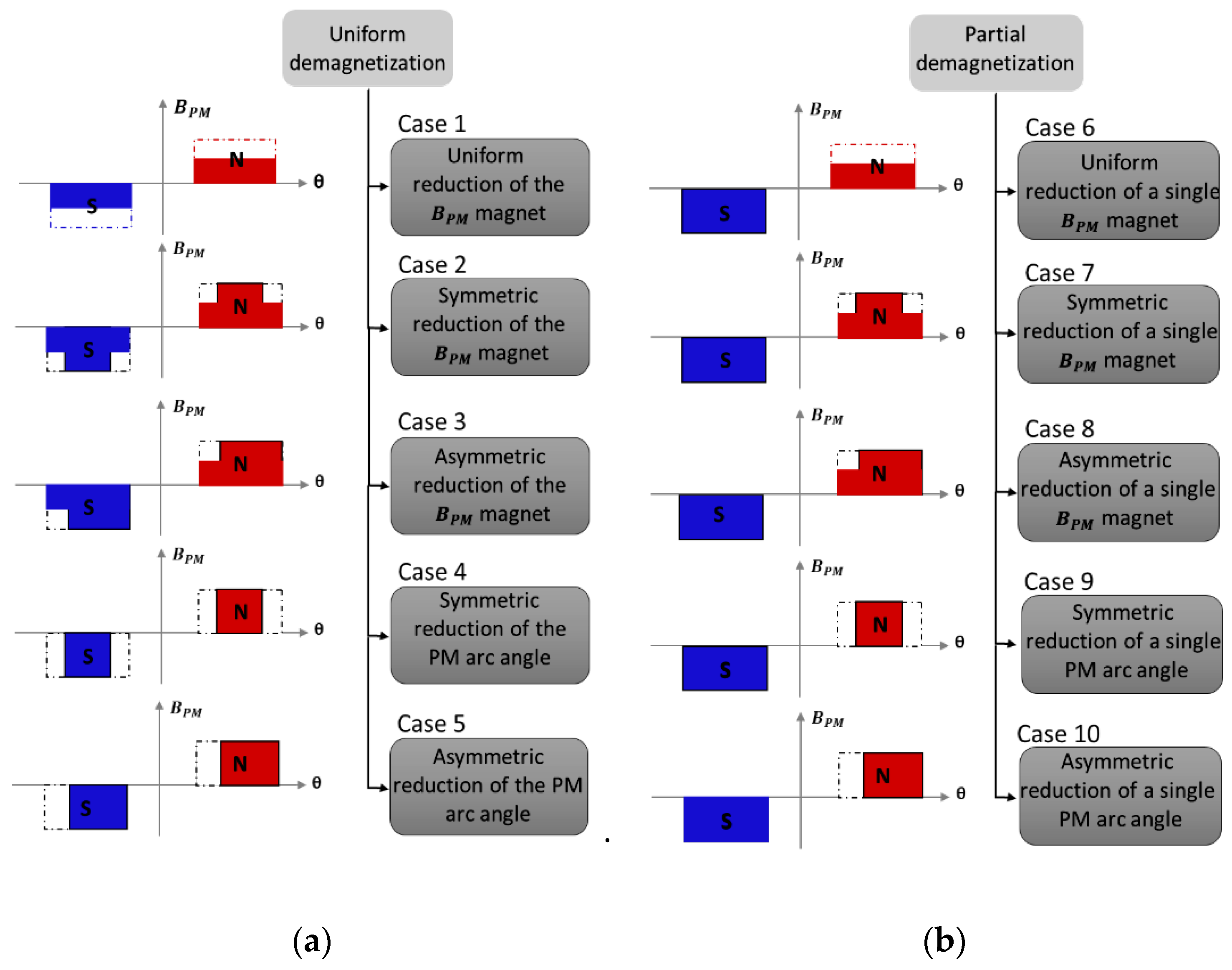
From a fault diagnosis viewpoint, the DMF can be local or uniform. Depending on the fault-induced PM field distortion nature, distinct PM faults examined in this work are clarified by
Figure 2 and categorized into two different groups: The uniform demagnetization faults and the partial demagnetization faults respectively shown in
Figure 2a,b. The uniform demagnetization takes place when all existing PMs in the motor are demagnetized with the same pattern and level [
29]. This fault is addressed in the following five distinct fault scenarios, which are examined based on FEM: Uniform (case 1), a symmetric (case 2) and asymmetric (case 3) reduction of the
BPM magnet, a symmetric (case 4) and asymmetric (case 5) reduction of the PMs arc angle (broken magnets). Similarly to the uniform demagnetization, five different situations of a local demagnetization fault are dealt with in this work by one faulty magnet out of eight: Uniform (case 6), a symmetric (case 7) and asymmetric (case 8) reduction of the
BPM magnet, a symmetric (case 9) and asymmetric (case 10) reduction of the PM arc angle.
In the following, a brief discussion is provided regarding the effect of these faults on the PMSM intrinsic parameters. For further development the reader can refer to [
32] and the references therein.
2.1. Healthy Conditions
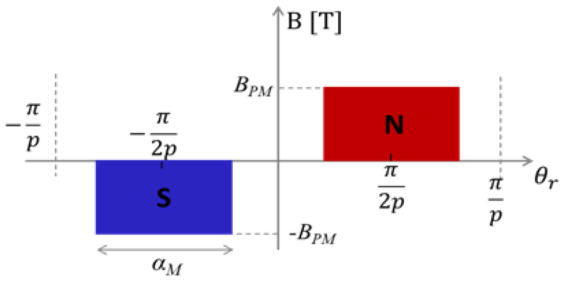
The idealized airgap flux density generated by the rotor surface mounted PM (
BPM) under a normal state is shown in
Figure 3.
The normal rotor magnetic flux density distribution,
B, as a function of rotor position,
θr, for an arbitrary p-pole-pairs motor, can be described as in [
29]:
with
where α
M is the arc angle of the PM in mechanical degrees,
θr is the angular position of the rotor in mechanical degrees,
p is the pole-pairs number, (
BPM)
n is the nth order PM flux density distribution Fourier coefficient, and n is the harmonic order (
n = 1, 3, 5…).
The airgap flux distribution defined in (1) is a periodic, odd function with half cycle symmetry and as such, will contain odd harmonics [
29]. These, generally, will in turn create in the signal of the stator current odd harmonic components of the fundamental frequency,
fh:
where
k is an integer (
k = 1, 2, 3…) and
fs is the PMSM supply frequency (in our case, equal to 188.3 Hz).
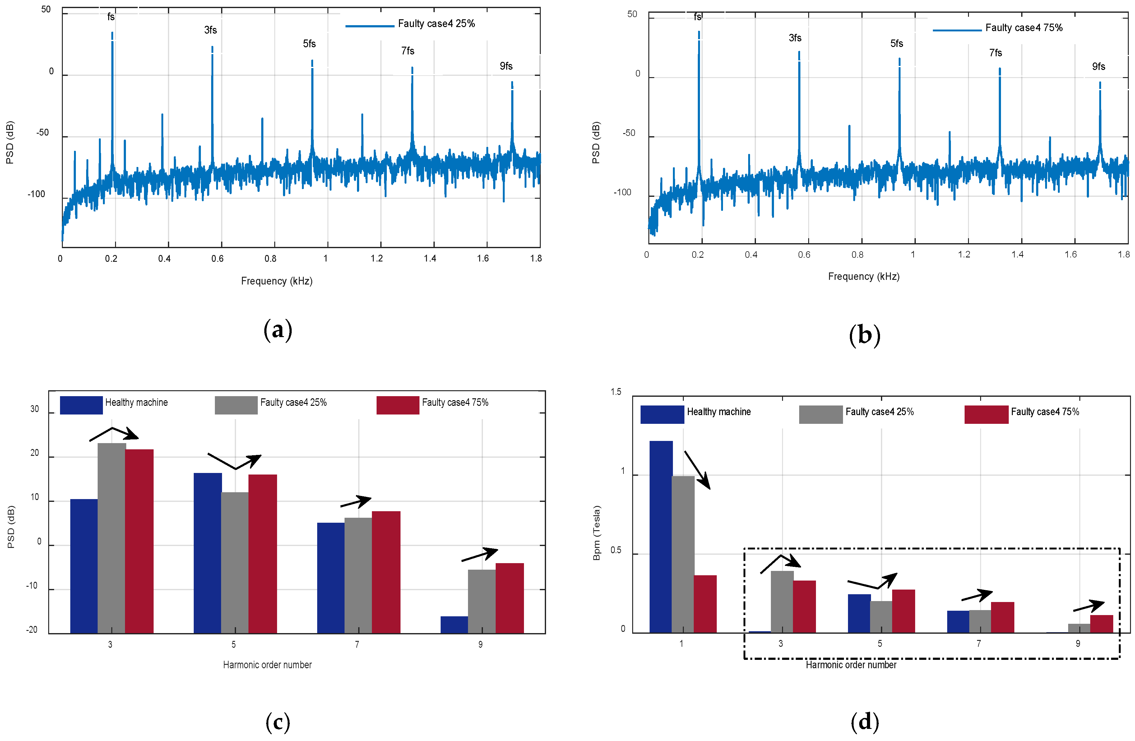
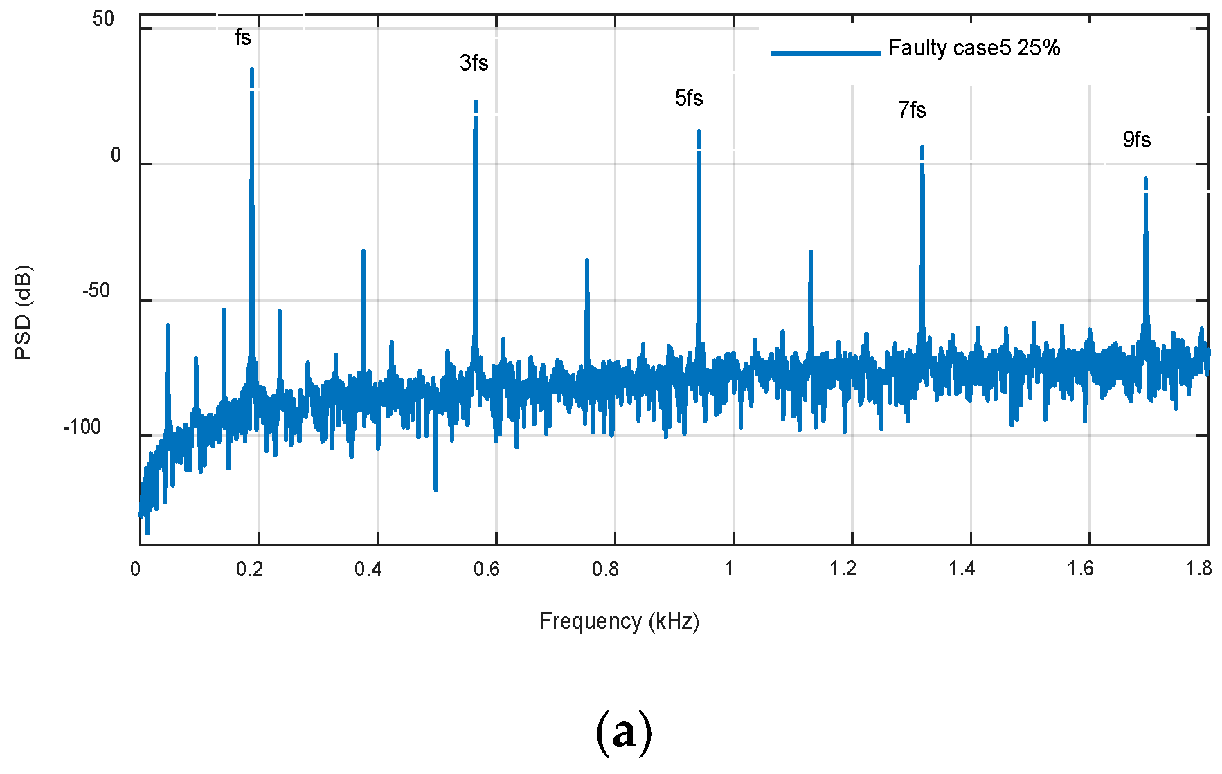
2.2. Uniform Demagnetization Fault Conditions
Depending on the defect nature, a PM DMF will produce a distinct disturbance in the PM normal field distribution pattern. When a uniform DMF takes place, the PM field harmonics generated by the fault do not modify the half-cycle symmetry or the odd periodic spatial distribution of the PM field and hence only creates changes in the harmonic orders amplitude, which should exist in the airgap of a machine with healthy magnets as shown in Equation (3).
For brevity, only two of the given defect cases (case 1 and case 4) have been chosen for mathematical modeling of possible magnetic field spectral content. For example, assuming an arbitrary magnitude reduction in the airgap flux density to
MBPM as defined in fault case 1 or an arbitrary reduction of the PM arc angle to
XαM following fault case 4. Therefore, the harmonic series in (1) will be changed to (4) or (5), respectively, where
X is the arc angle fault severity index and
M is the flux magnitude fault severity index.
X can be from 0 (total reduction of the PM arc length) to 1 (healthy PM), and
M can be from 0 (total demagnetization) to 1 (healthy PM). It is clear from Equations (4) and (5) that the uniform demagnetization will not change the airgap field harmonic content. However, the existing harmonics magnitudes will change depending on the uniform fault type and severity. Hence, the possible frequencies of the stator current spectrum for a uniform demagnetization fault,
fUD, will be similar to those presented in the healthy motor [
29]:
Different PM faults nature or severities of PM faults would create distinct harmonics magnitude patterns in the signal of the stator current as expressed in Equations (4) and (5).
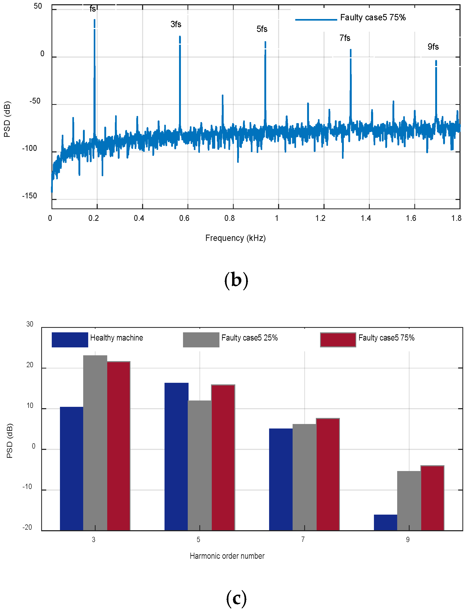
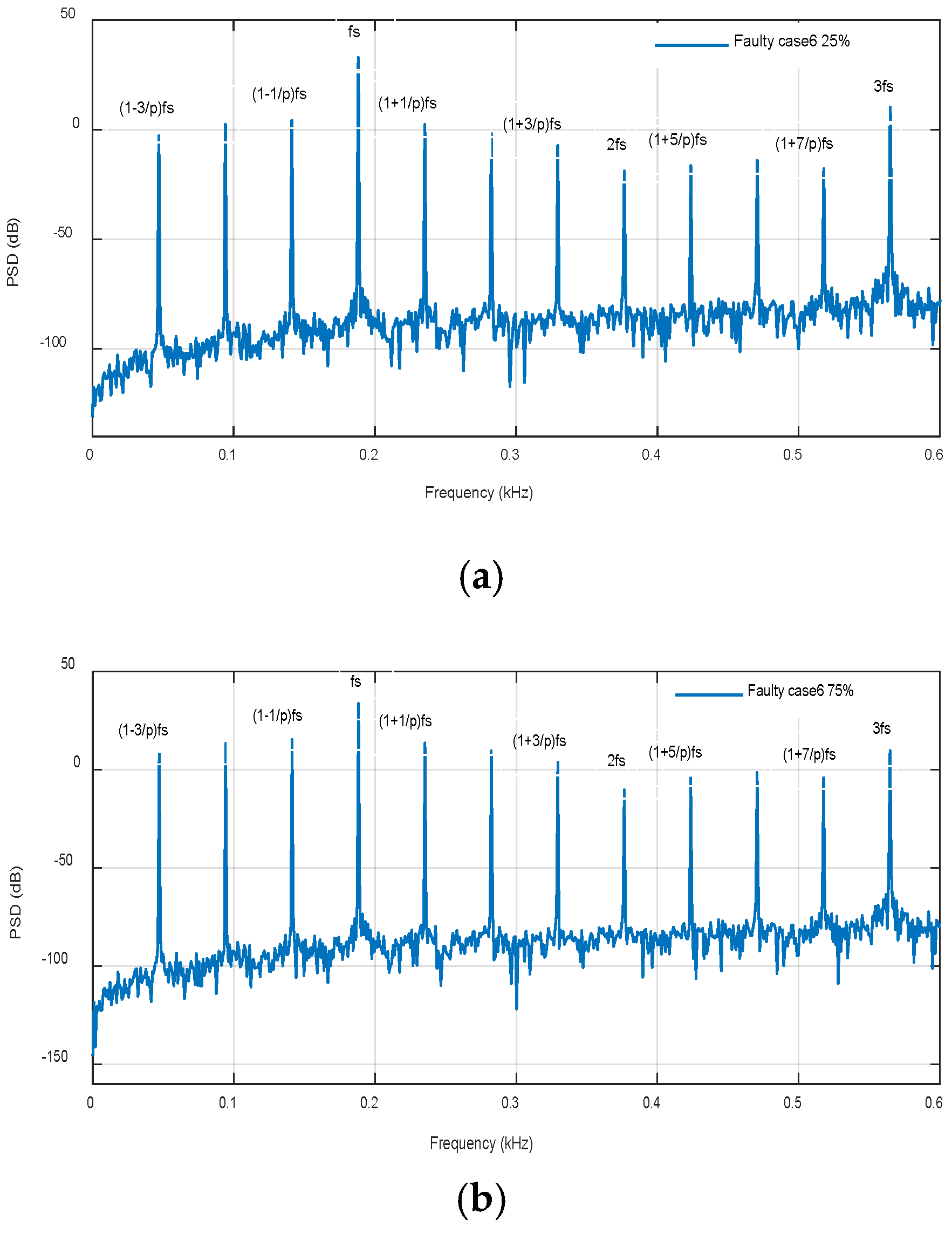
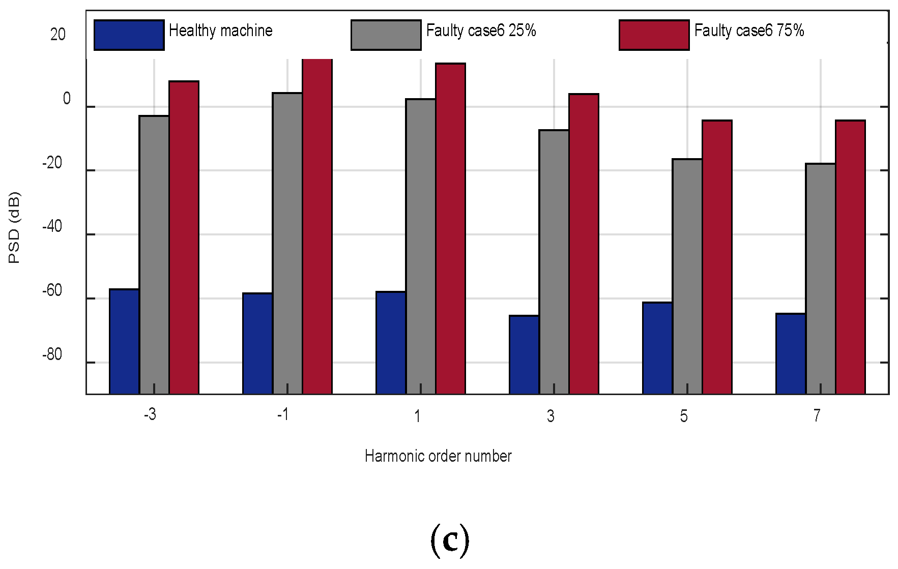
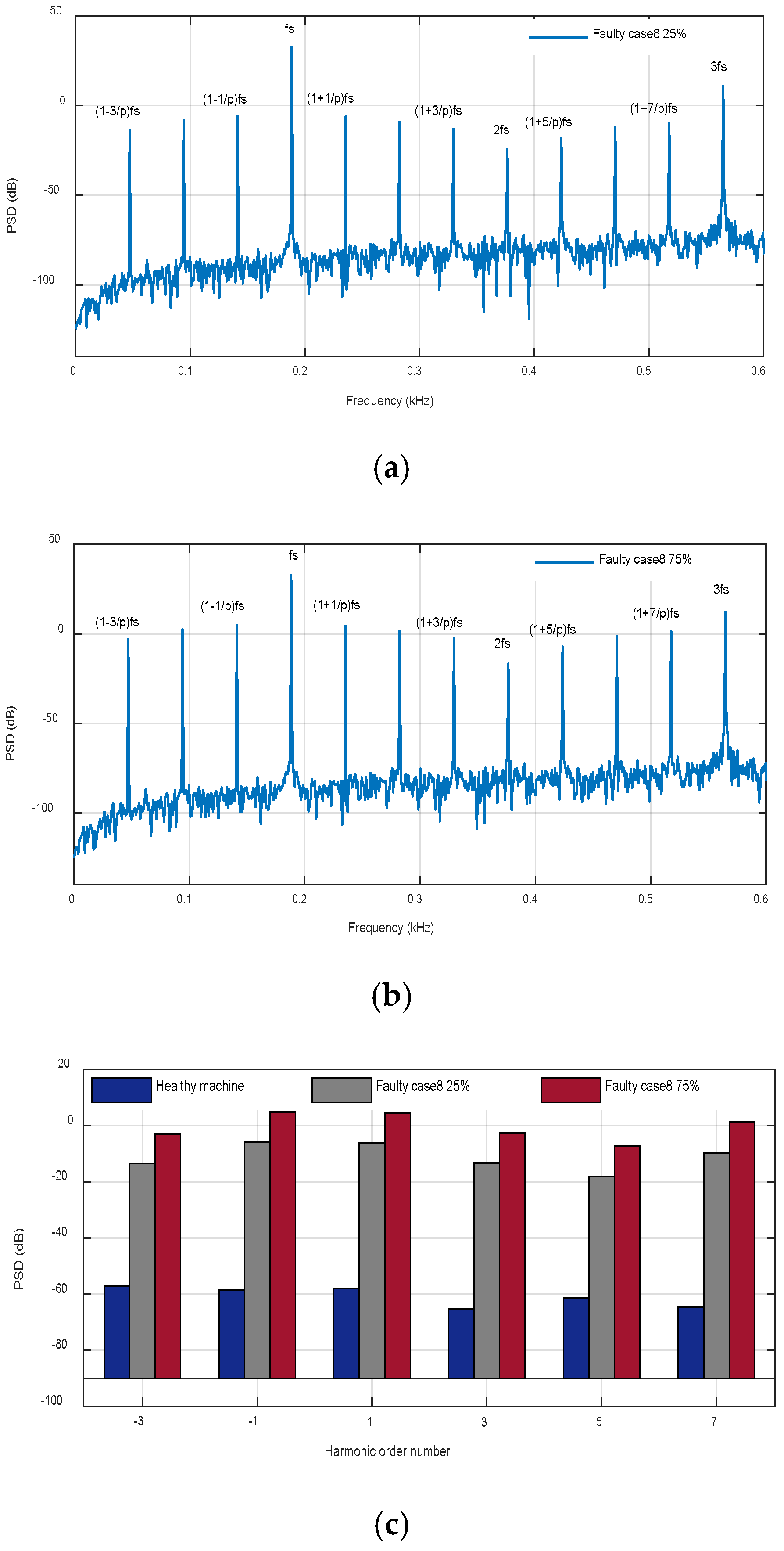
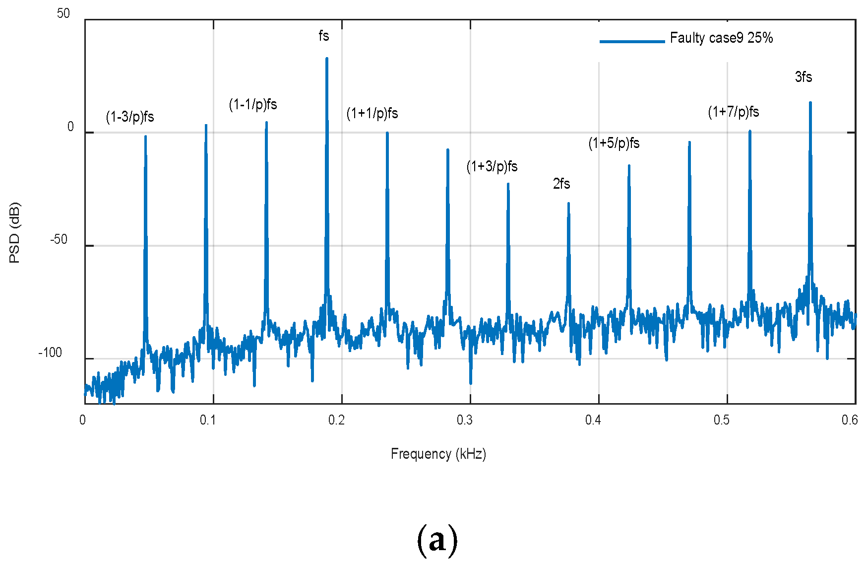
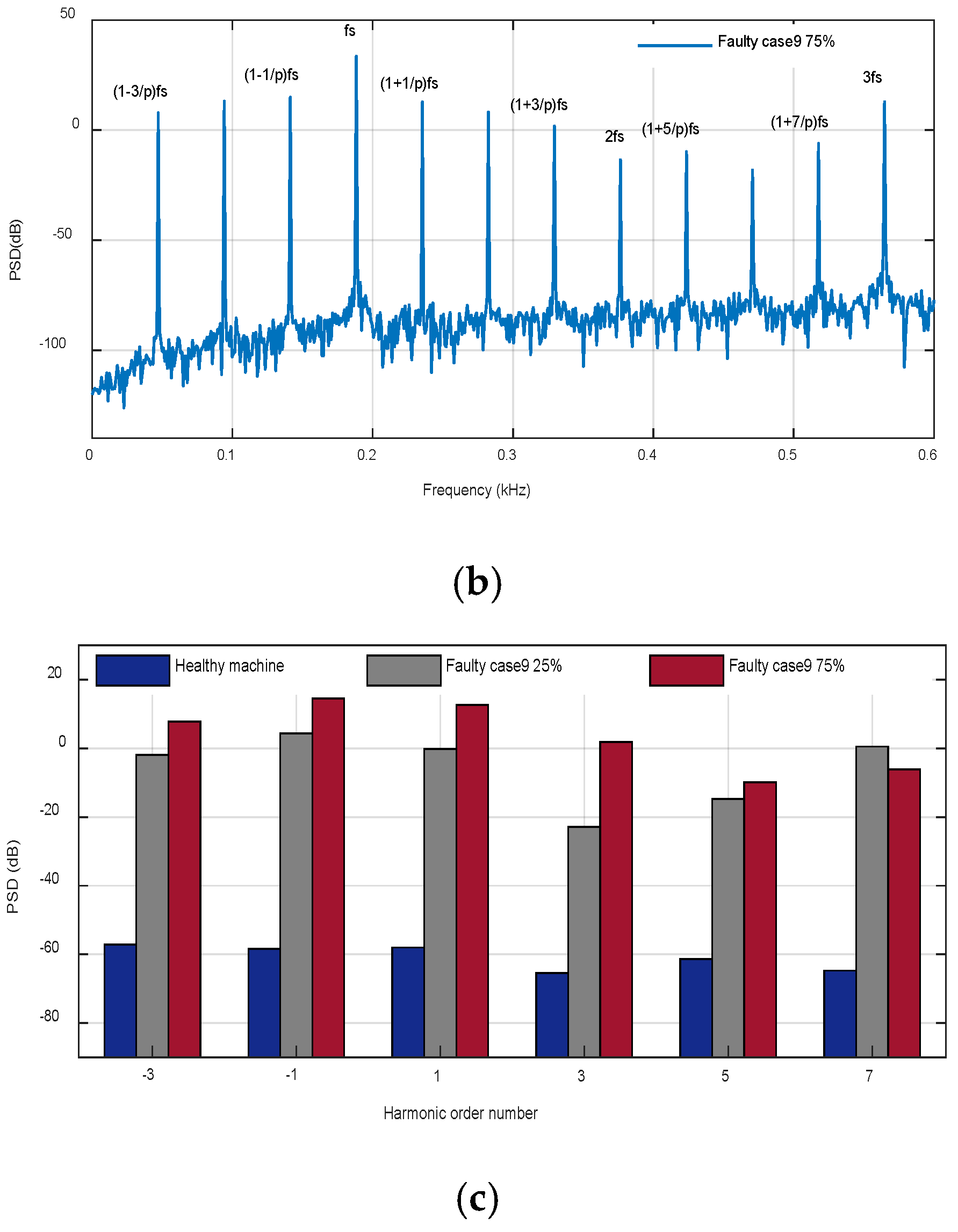
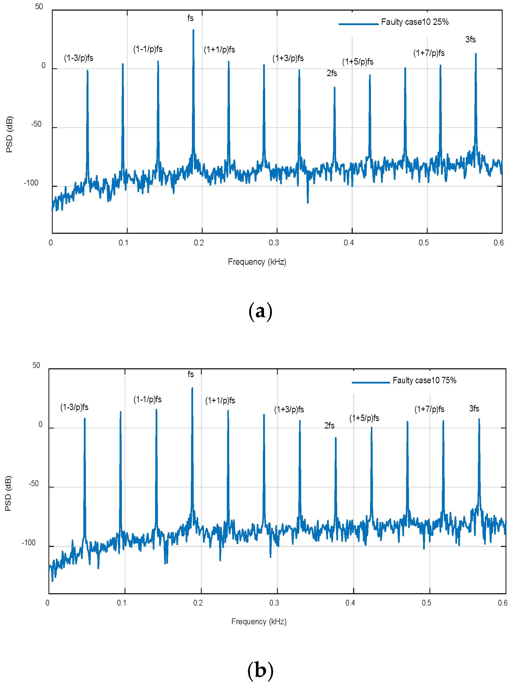
2.3. Partial Demagnetization Fault Conditions
For local faults in a single PM segment considered in cases 6–10 in
Figure 2, the field distribution property of the half cycle symmetry is compromised. Therefore, with existence of any local PM damage, sub-harmonics of the fundamental frequency appear in the stator current, which are defined as in [
29]:
where
fLD defines the fault signature of the local PM demagnetization fault,
fs is the electrical fundamental frequency, and
k is an integer.
2.4. Analyses Methods
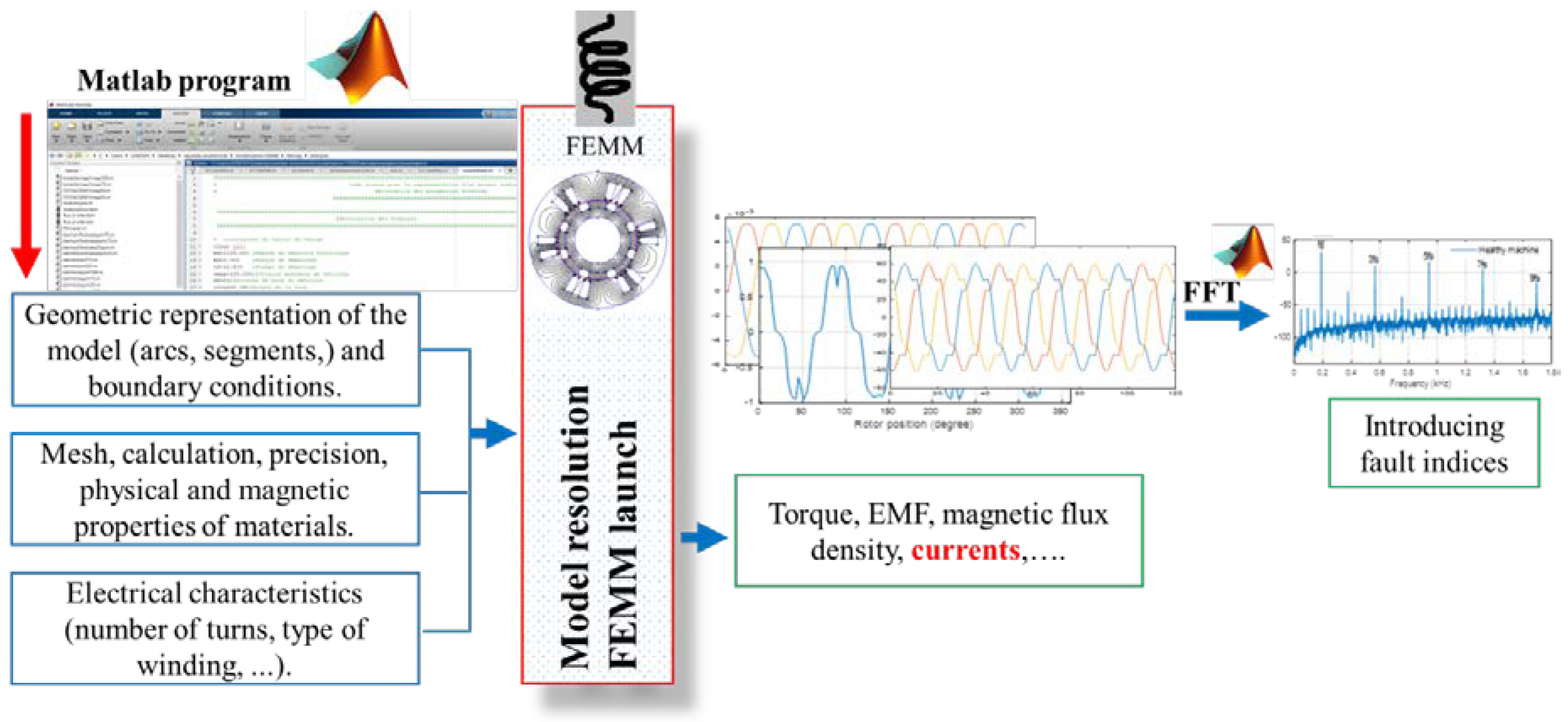
This work deals with ten cases of a demagnetization fault. To determine the behavior of PMSM under healthy and faulty conditions, a 2D FEM model is proposed. This model is developed to characterize the DMF phenomenon. Simulation results based on FEMM (finite element method magnetics) and MATLAB software help in significantly understanding the effects of these defects on intrinsic parameters of PMSMs. Indeed, the finite element method using FEMM is carried out to study and determine the electromagnetic quantities of the motor. The simulation process is based on three steps:
Pre-processing (motor definition), which consists of providing the information necessary for the representation of the motor geometry, allows defining the mesh sizing for each section, as well as the definition of the physical properties of each material. A MATLAB script allows defining the motor geometry and materials proprieties.
Processing, which consists of solving the magnetics problem. This step is performed by the FEMM software.
Post-processing, which allows the computation of many local or global quantities (inductance, torque, EMF, flux linkage, currents, etc.). Specifically, it allows computing the currents spectrum in order to characterize magnets demagnetization faults.
Figure 4 presents the overall process for motor definition, simulation, and results processing using both MATLAB and FEMM.
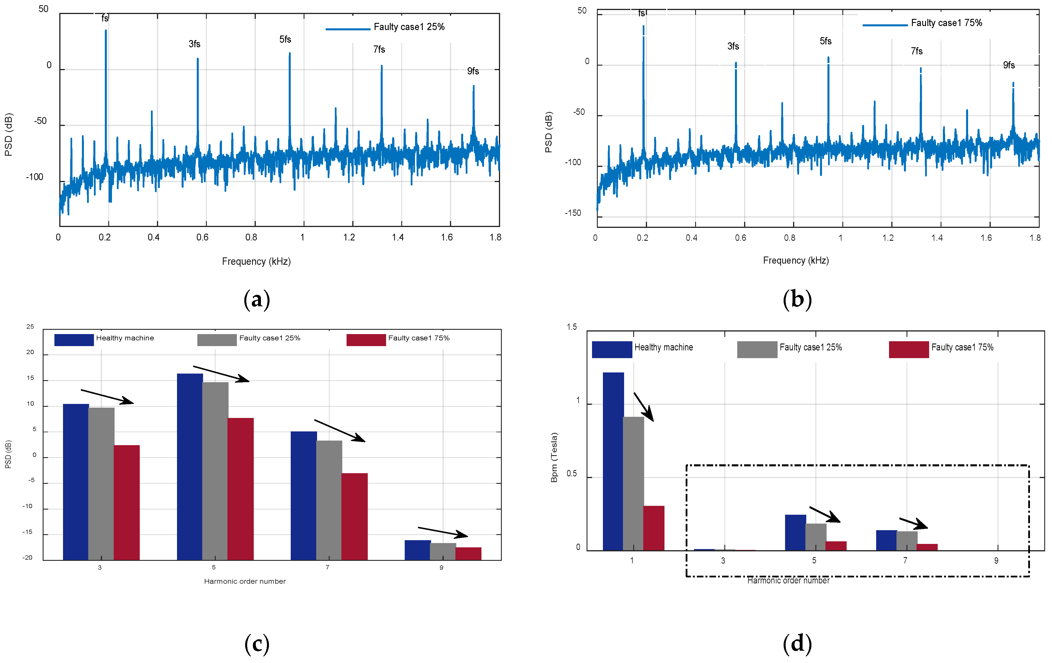
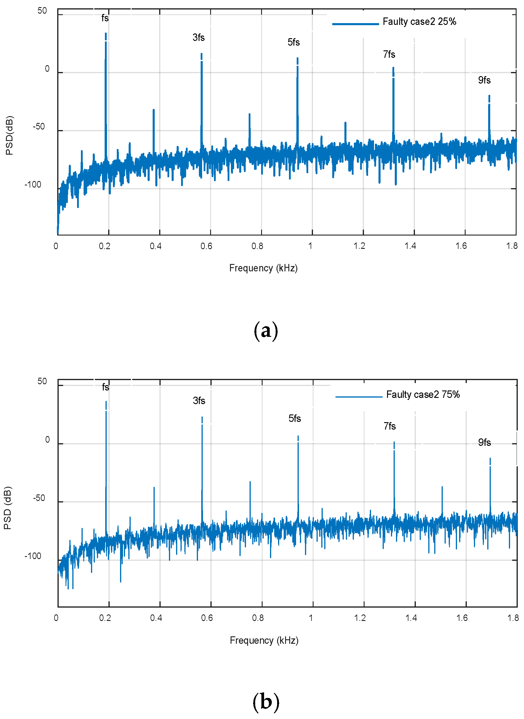
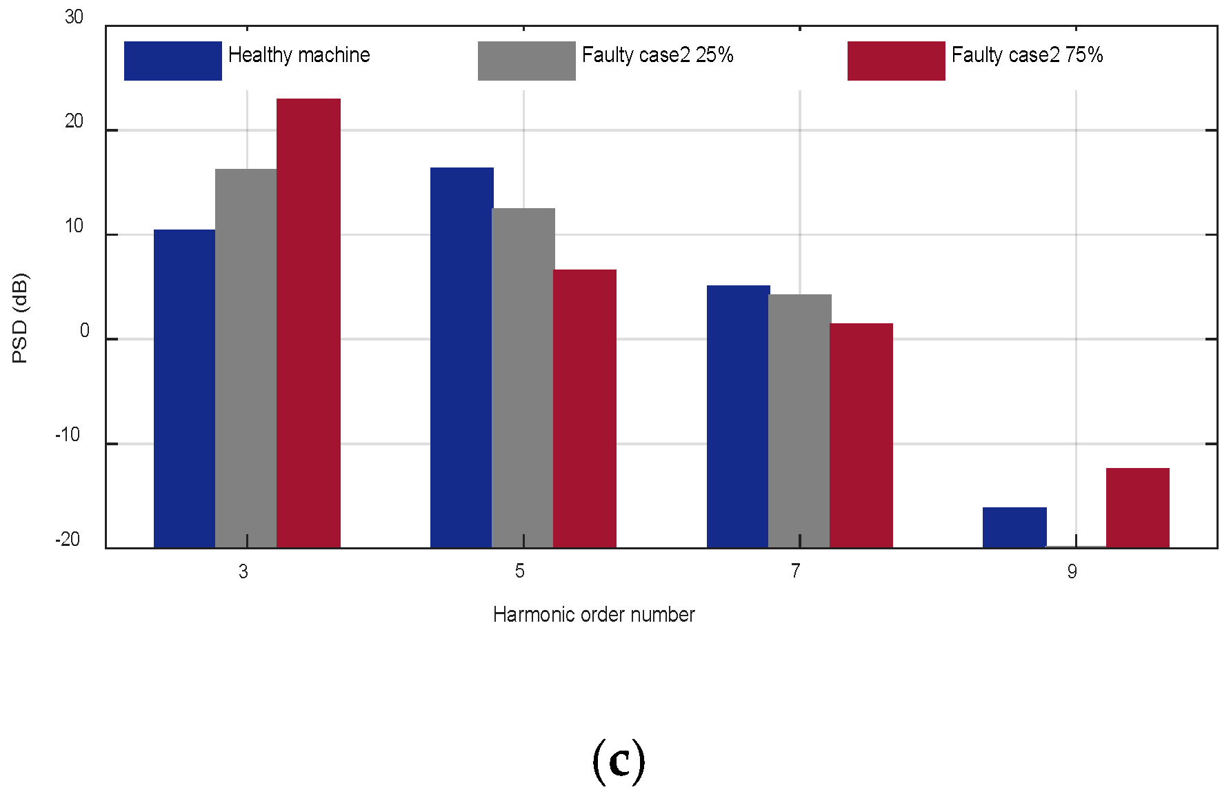
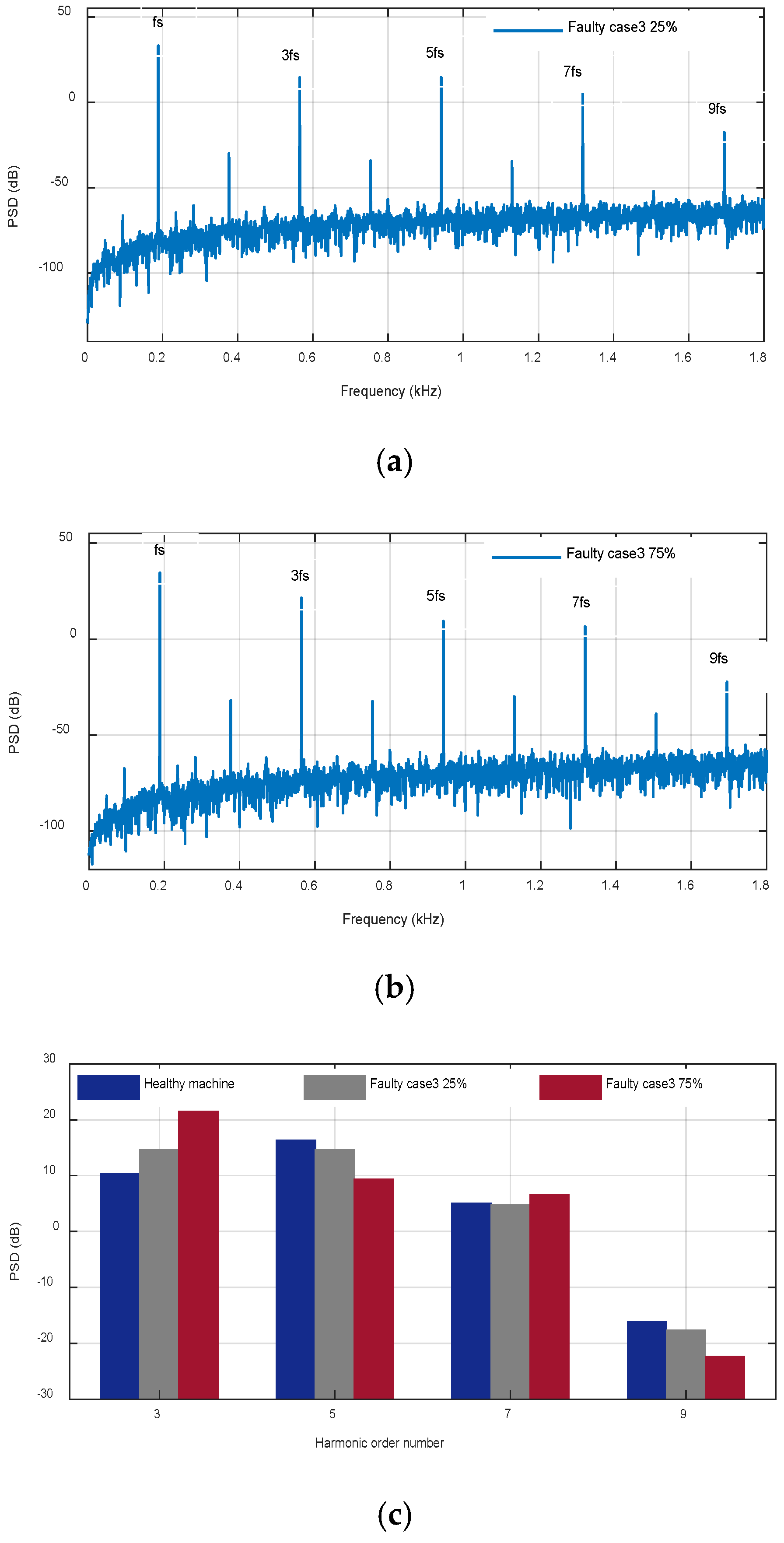
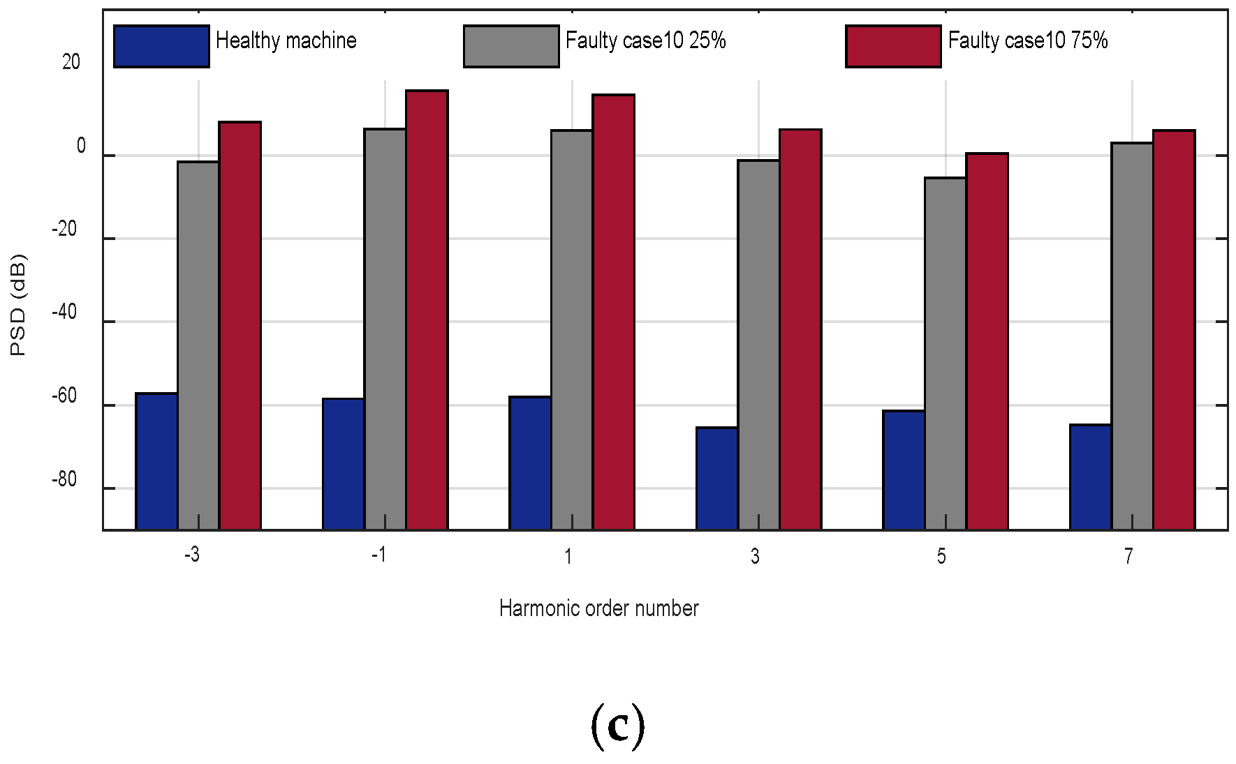
PMSM is simulated and studied under healthy and different degrees of fault severity to get an adequate data set of motor behavior under faulty conditions, which would provide the needful dataset to set up an efficient fault detection method. The resulting airgap magnetic flux density, flux linkage, stator currents, and EMFs are studied under both a uniform and partial demagnetization fault. The stator currents PSD are computed using FFT. Then, the currents spectrum under a healthy and faulty PMSM are evaluated and compared to achieve an effective procedure to detect each of the demagnetization fault scenarios. A novel frequency pattern in the DMF case is introduced, and the amplitude of sideband components (ASBCs) at frequencies obtained from the frequency pattern is used to detect distinct defect cases.
3. Finite Element Analysis Simulation Results
An electrical machines’ modeling under faulty conditions is a section of the fault detection system. It is the first stage towards an electrical motors fault diagnosis. Consequently, it is mandatory to simulate the motor under several faulty cases such as DMF to analyze their characteristics and check out its performance. Thus, fast and valid models are needed to achieve this goal. FEA is commonly employed for proper modeling of DMF. It treats all the magnetic, mechanical, electrical, and geometric proprieties of motor parts under study and gives realistic and higher accuracy results, which are useful to confirm the output signals of other modeling methods. In this work, different types/degrees of DMF are simulated via the 2D-FE method.
The machine was simulated under a partial and uniform demagnetization fault. FEA simulations were carried out for the studied cases to illustrate and investigate the manifestation of the spectral patterns induced by the defect and observed for a larger set of fault severity. Different severities of defect can be studied by this model. In order to prove the effectiveness of the results, different severities of DMF from 25% to 75% have been simulated for the studied motor using the proposed model.
For cases 1, 2, 3, 6, 7, and 8, the chosen magnets material was removed with another one that has the same conductivity and relative permeability as the healthy PM but a lower magnetic flux density BPM compared to the healthy magnet. A reduction of 25% (M = 0.75) and 75% (M = 0.25) of the healthy BPM was considered to illustrate the uniform and local demagnetization. For the remaining cases 4, 5, 9, and 10, the damage of the magnet was presented by modifying the PM geometry accordingly for each defined PM defect scenario. A reduction of 25% (X = 0.75) and 75% (X = 0.25) of the healthy PM αM was simulated to illustrate the reduction of the arc length magnet in the cases of the uniform and partial demagnetization.
3.1. Finite Element Study under Healthy Conditions
The analyzed machine geometry and its design parameters presented in
Table A1 in
Appendix A are used to develop a two-dimensional finite element motor model presented in
Figure 5a.
To examine the differences in the content of harmonics and sub-harmonics signal between healthy and faulty motors, it is needed to use the healthy motor as a reference pattern. This leads to directly compare machines with numerous defects and recognize the changes in the fault features location.
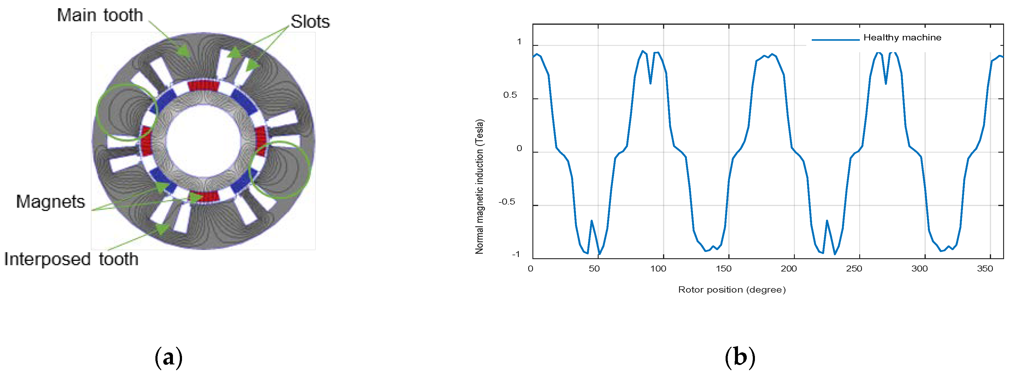
Figure 4 presents, as a function of the rotor position, the magnetic field distribution of the PMSM and the airgap magnetic flux density obtained under healthy conditions.
The studied motor is a PMSM consisting of four pairs of poles and six main teeth, as shown in
Figure 4a. Between the two main teeth, an interposed tooth is added to improve the wave form and reduce the leakage rate. Each phase winding is formed of two diametrically opposed coils whose windings are concentrated, which means that the circles of the coil are wounded directly around a stator tooth. The field is seen to be distorted, as shown in green circles, because there are two different magnets (S and N) close to the main tooth.
3.2. Finite Element Study under Uniform Demagnetization Fault
3.2.1. Simulation Results
In order to point out the influence of uniform DMF cases defined in
Figure 2, in the machine airgap magnetic field,
Figure 6,
Figure 7,
Figure 8,
Figure 9 and
Figure 10 present, as a function of the rotor position, the magnetic field distribution and the airgap magnetic flux density.
Figure 11,
Figure 12 and
Figure 13 present, respectively, the flux linkage, the electromotive forces (EMFs), and the current phase as a function of time, of the five uniform demagnetization cases with a 75% fault severity in comparison with healthy conditions.
3.2.2. Uniform Demagnetization Fault Results Analysis
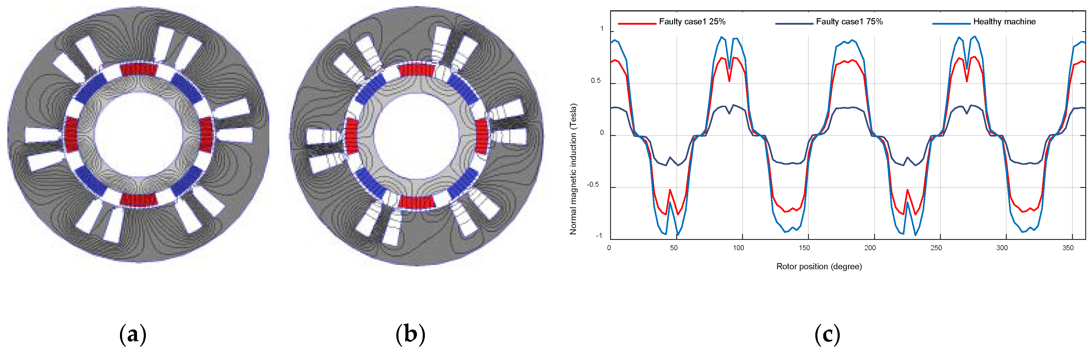
From the results presented above, demagnetization disturbs the airgap flux distribution. Since the magnets are in a uniform demagnetization, even though the faulty curves in
Figure 6c revolve at the synchronous speed, it exhibits the same shape but a less magnitude value than in the healthy case. The remaining cases shown in
Figure 7c,
Figure 8c,
Figure 9c and
Figure 10c disturb the airgap flux density in the shape and in the magnitude since the defect is not distributed in a balanced way in all the parts of the magnet (symmetric and asymmetric defect).
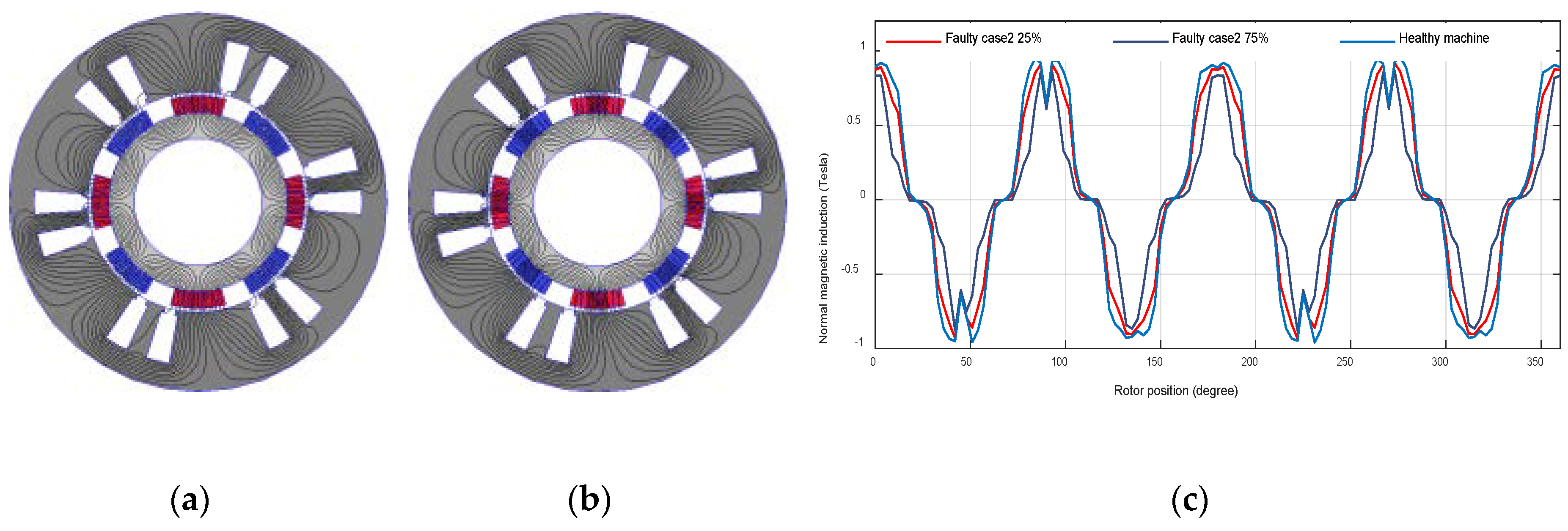
The obtained result for the symmetric reduction of the
BPM magnet case in all the rotor poles is given in
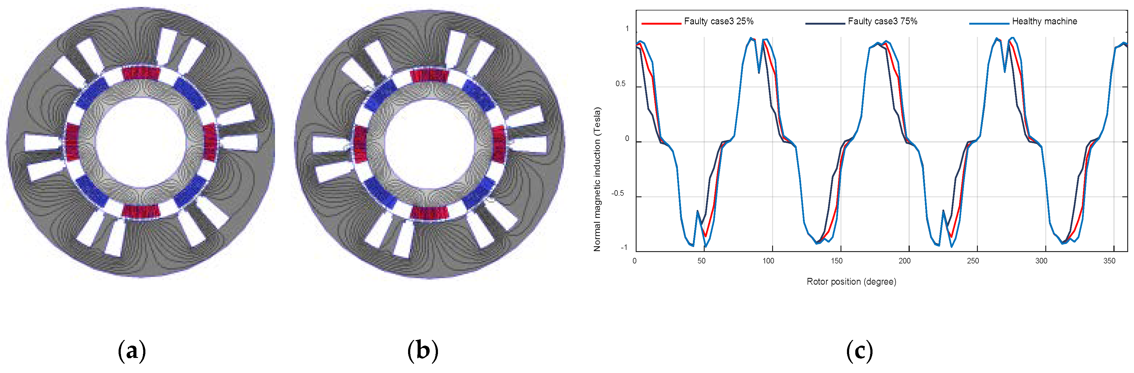
Figure 7c. In this case, the same appearance was obtained as the healthy case but the widths of the sinusoids are reduced symmetrically. On the other hand, in case 3, an asymmetric reduction of the
BPM magnet, presented in
Figure 8c, the widths of the sinusoids are reduced asymmetrically since the defect is distributed in a balanced way in all the parts of the magnets.
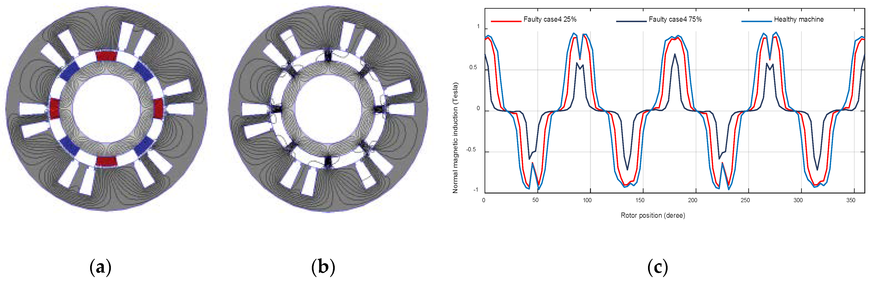
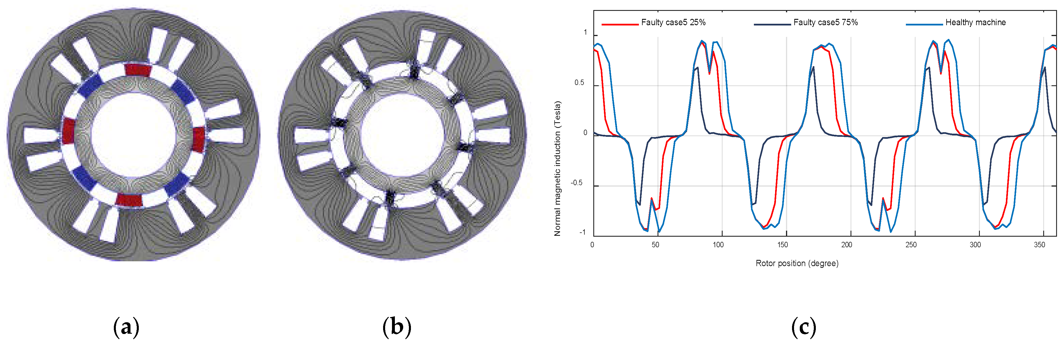
The results depicted in
Figure 9c and
Figure 10c, respectively, for the cases of a symmetrical (case 4) and asymmetrical (case 5) breakage in all the rotor poles indicate the same shape as the healthy case with lower amplitudes and symmetrically (case 4) and asymmetrically (case 5) reduced sinusoids widths.
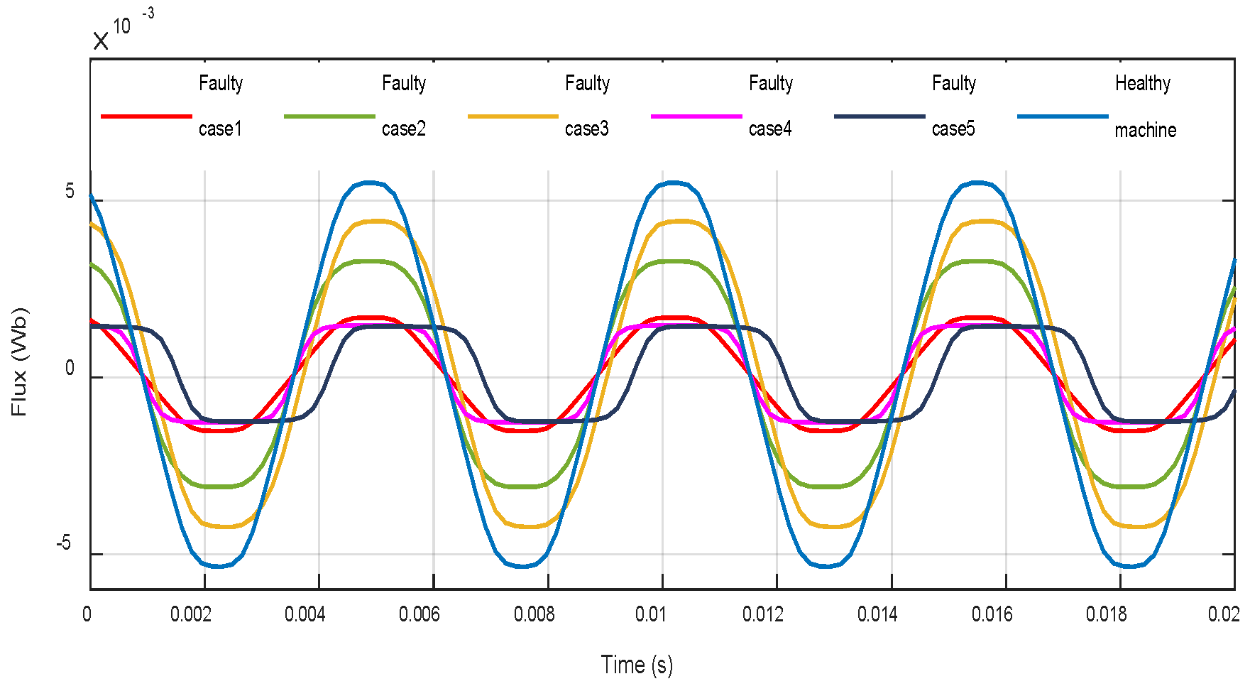
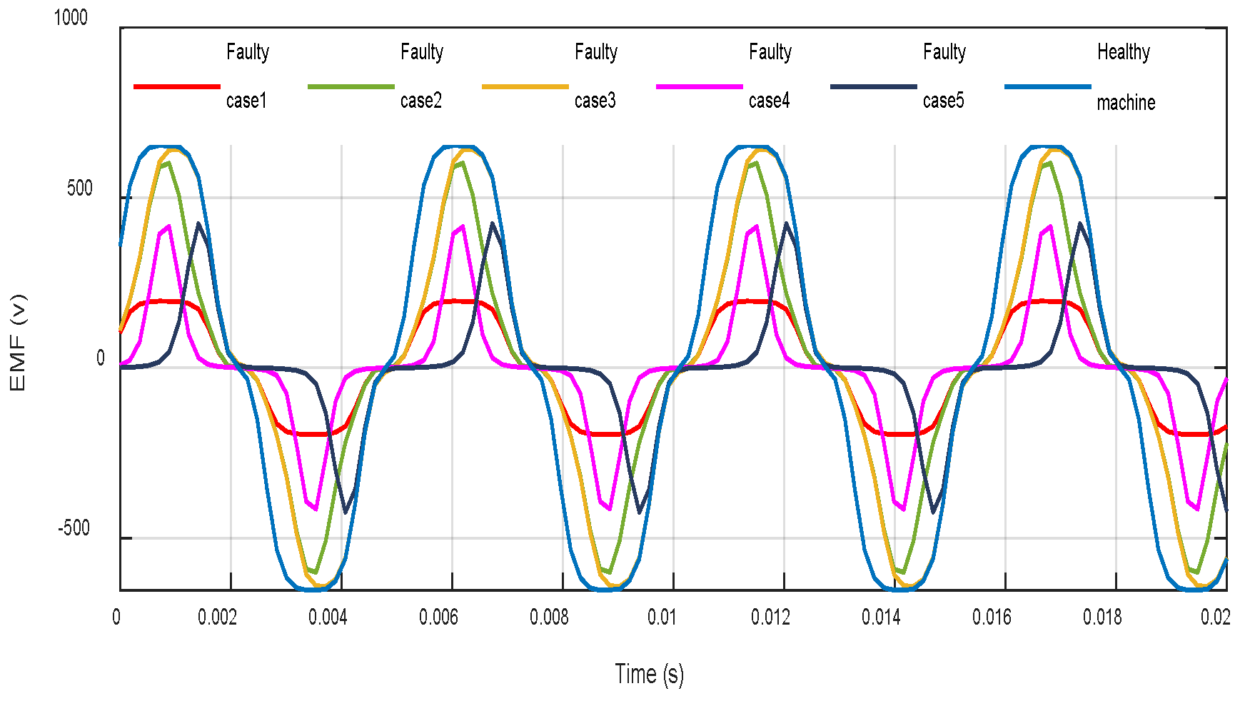
The results in
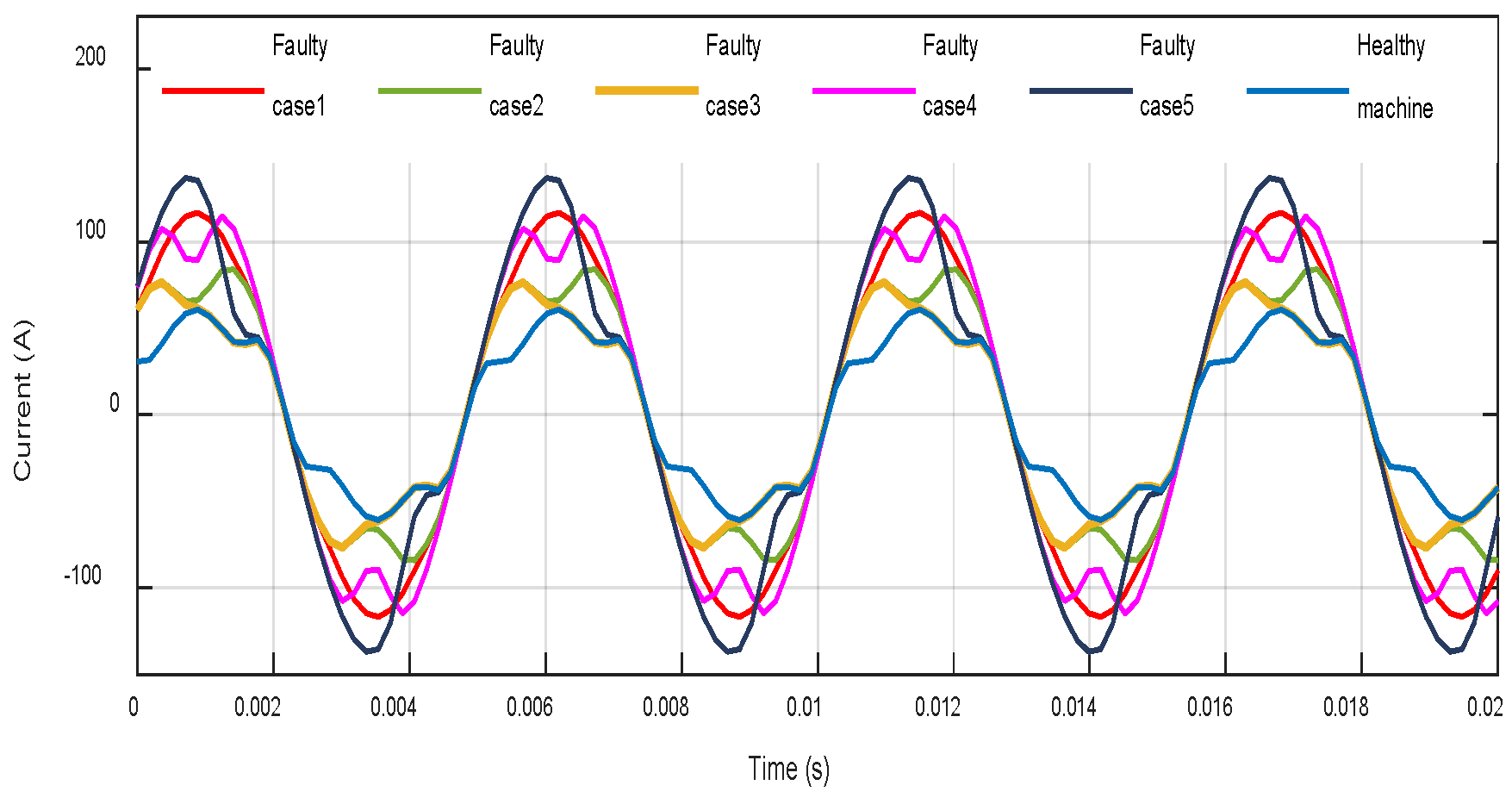
Figure 11,
Figure 12 and
Figure 13 show, respectively, the influence of a 75% uniform demagnetization fault in the flux, EMFs, and current compared to a healthy machine. The demagnetized PMs produce less flux than healthy PMs (
Figure 11), weaken the EMFs (
Figure 12), and increase the current in the windings (
Figure 13) over the machine parts. It is obvious from
Figure 13 that cases 1, 4, and 5 produce a very strong current unbearable for the studied machine. Consequently, it is necessary to stop the machine operation to avoid a catastrophic failure due to demagnetization defects.
3.3. Finite Element Study under Partial Demagnetization Fault
3.3.1. Simulation Results
3.3.2. Partial Demagnetization Fault Results Analysis
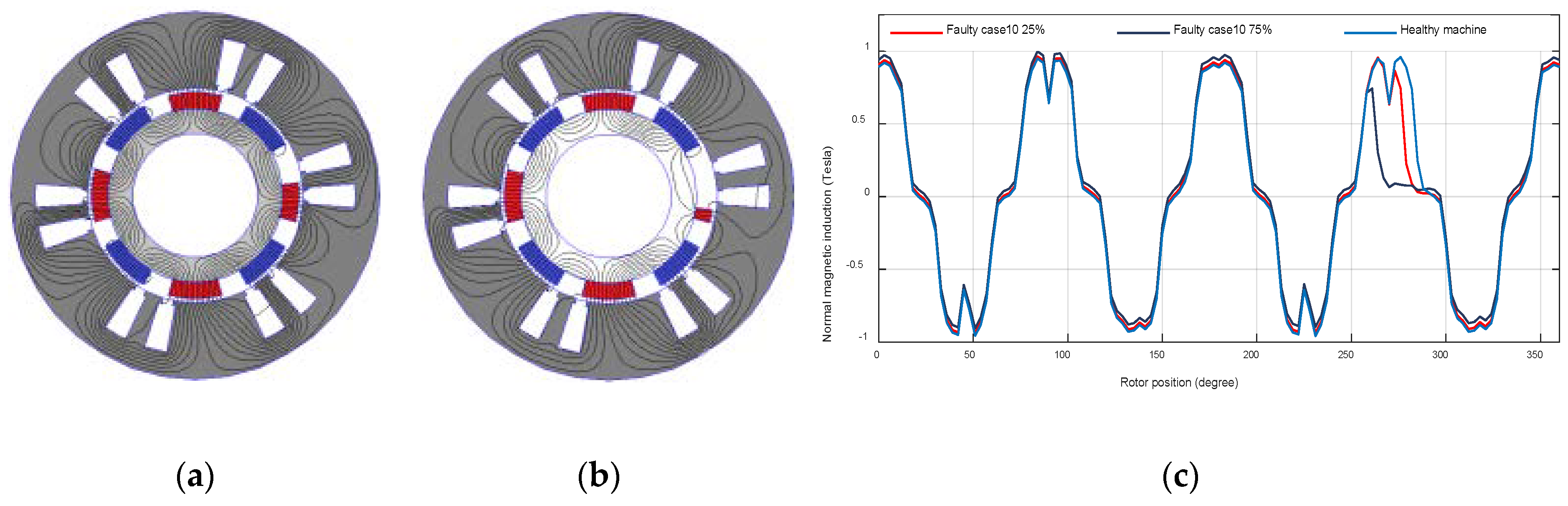
In the case of a partial demagnetization fault shown in
Figure 14c,
Figure 15c,
Figure 16c,
Figure 17c and
Figure 18c, a non-uniform magnetic flux density close to the damaged magnet is generated in the airgap. In addition, with the increase of fault severity, variations in the normal magnetic induction amplitude seems to be linear.
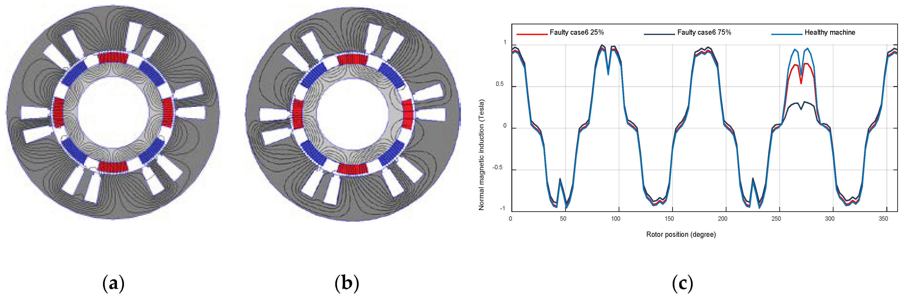
Simulation results of case 6, illustrated by
Figure 14c, exhibit the same shape but less magnitude value than in the healthy case close to the damaged magnet at the rotor angular position [255 285]°.
The obtained results for the symmetric reduction of a single
BPM magnet case in the rotor pole S at the rotor angular positions [255 264]° and [276 285]°, are given in
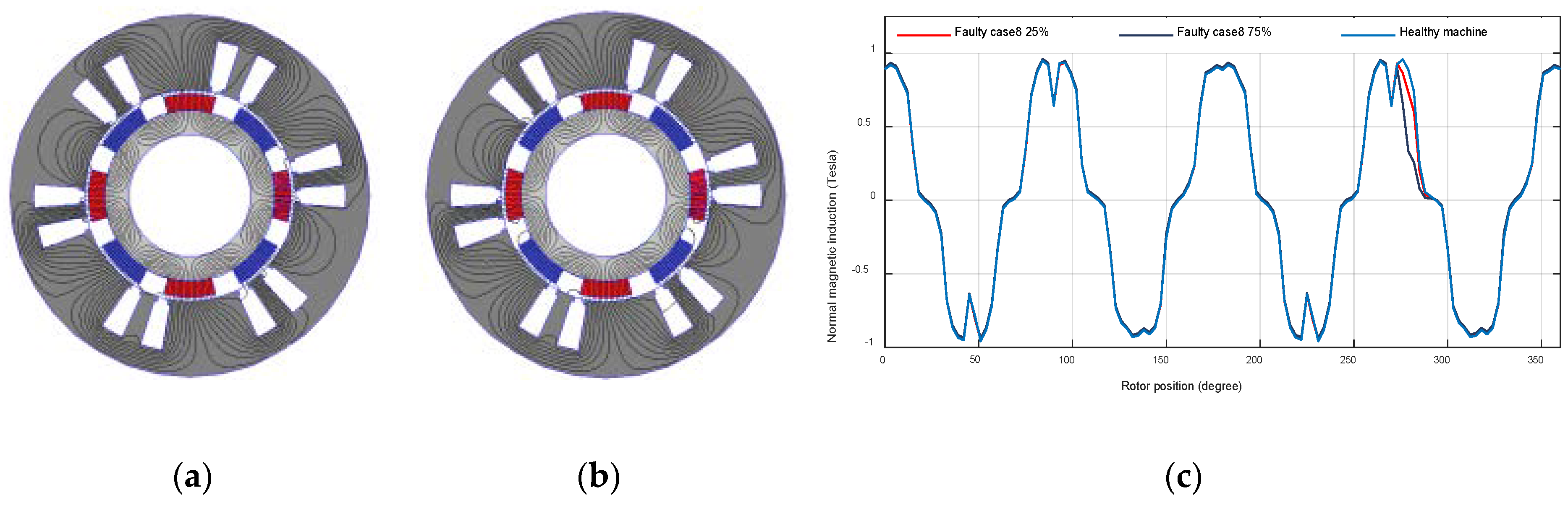
Figure 15c. In this case, we observe the same shape as the healthy case with symmetric reduced sinusoids widths except in the part where the magnet is damaged. On the other hand, in case 8, an asymmetric reduction of a single
BPM magnet at the rotor angular position [276 285]°, presented in
Figure 16c, the width of the sinusoid is asymmetrically reduced.
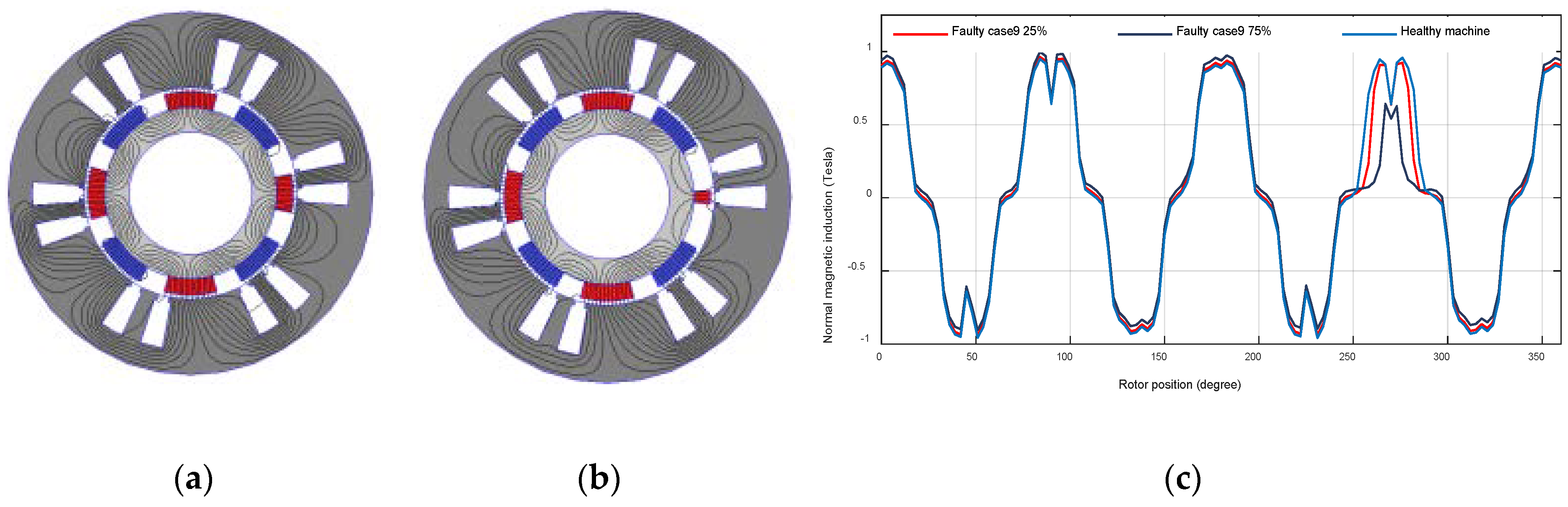
The symmetrical breakage defined by case 9 for different degrees of severity is shown in
Figure 17c. A symmetric breakage of ¼ of the magnet (25% severity degree), at the rotor angular positions [255 258.75]° and [281.25 285]°, and of ¾ (75% severity degree) of the magnet, at the rotor angular positions [255 266.25]° and [273.75 285]° have been considered. The obtained results indicate the same shape as the healthy case with less magnitude value and the sinusoids widths are symmetrically reduced close to the rotor position where the defect is introduced.
The asymmetric breakage defined by case 10 for different degrees of severity is shown in
Figure 18c. An asymmetric breakage of ¼ of the magnet (25% severity degree), at the rotor angular position [277.5 285]°, and of ¾ (75% severity degree) of the magnet, at the rotor position [262.5 285]° have been studied. The obtained results indicate the same shape as the healthy case with less magnitude value and the sinusoids widths are asymmetrically reduced close to the rotor position where the defect is achieved.
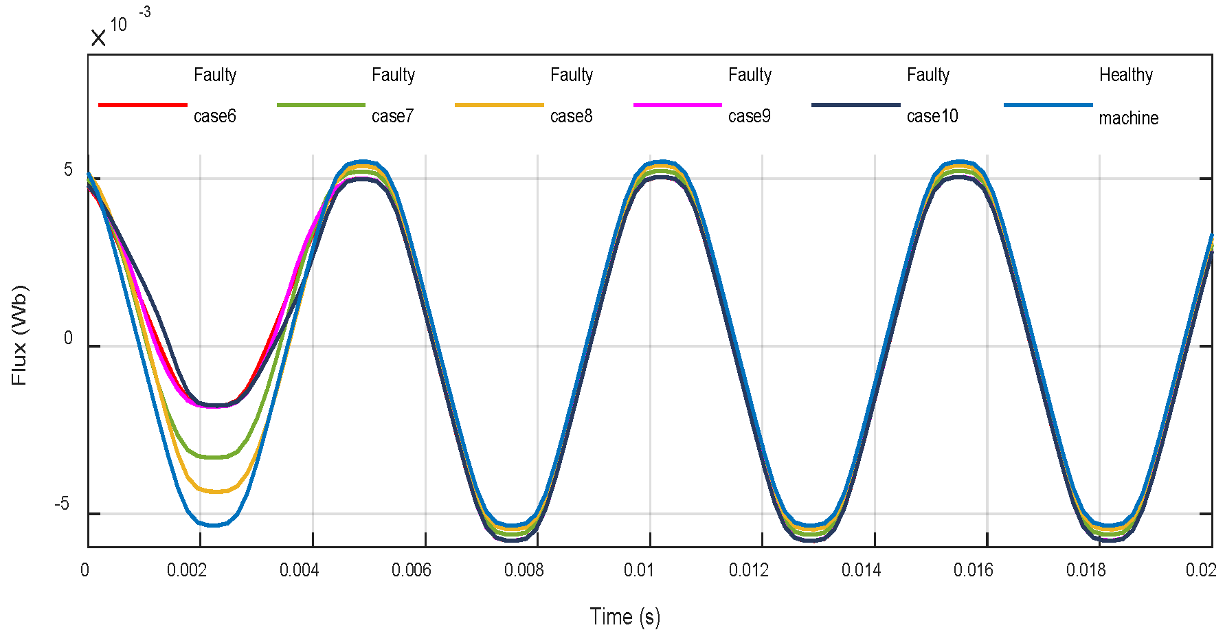
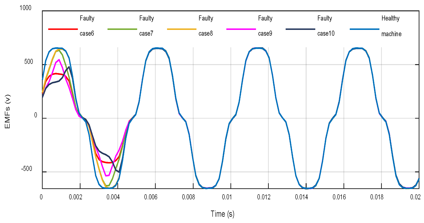
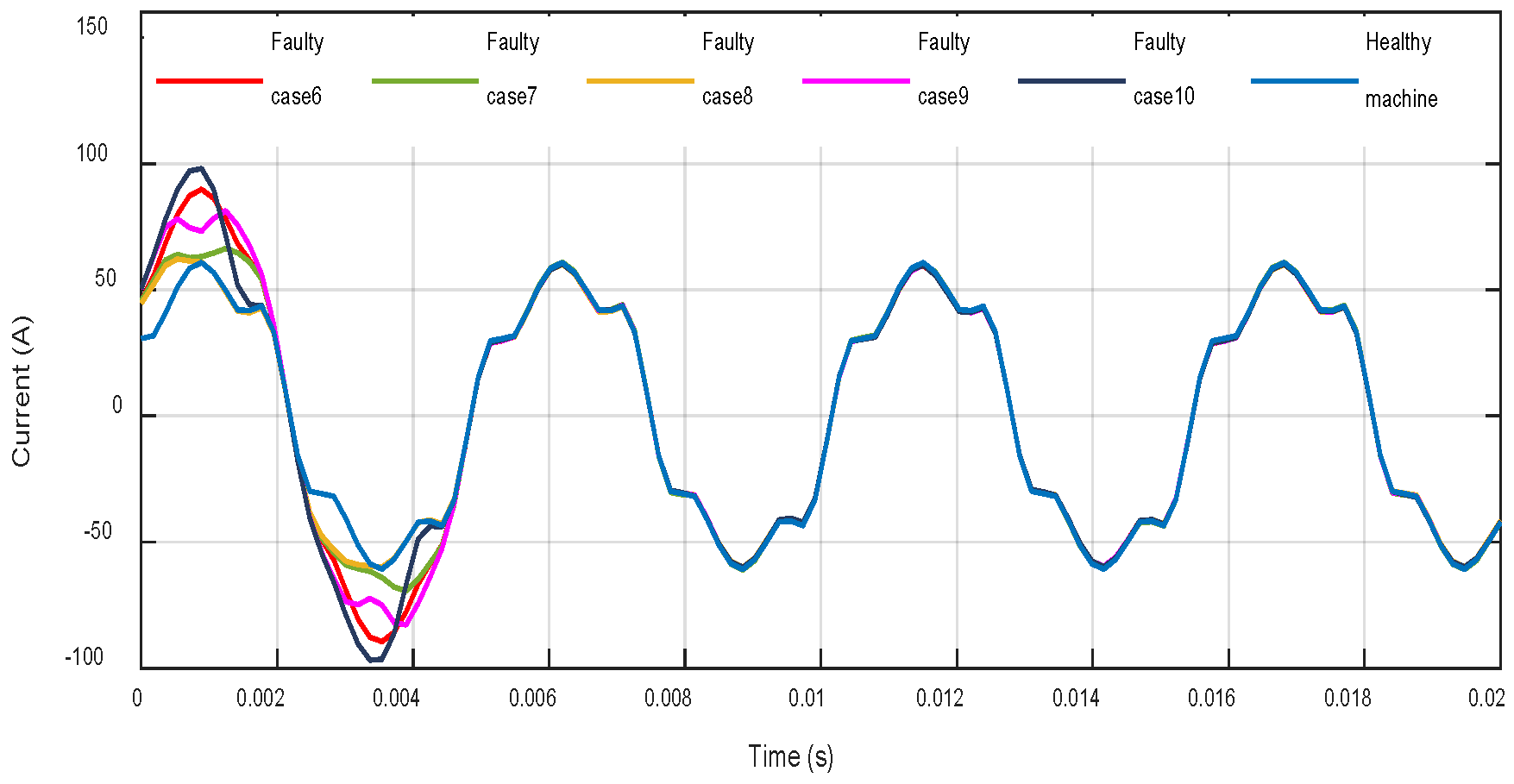
Results in
Figure 19,
Figure 20 and
Figure 21 show the influence of a 75% partial demagnetization fault in the flux linkage, EMFs, and currents compared to a healthy machine. The DMF effect on the motor is very severe. The defective PM produces less flux linkage than a healthy PM (
Figure 19), reduces the EMFs (
Figure 20), and leads to higher currents flowing in the machine windings (
Figure 21) (notably cases 6, 9, and 10), which may weaken the winding insulation and affect the machine performance and parameters. These signals have the same shape and the same amplitude except for the poles affected by the partial demagnetization fault.
5. Conclusions
This work has presented a FEA modeling investigation of a PMSM running under a set of various PM defects to extract, analyze, and correlate the fault signatures resulting from distinct predefined fault cases. One of the main reasons for diagnosing a demagnetization defect at the initial stage of its occurrence is the growing cost of NdFeB PMs and the need for a cost-effective condition monitoring in various industrial applications.
A study has been performed that links possible current spectral signature models to the nature of the PM field distortion resulting from a particular PM demagnetization defect. A mathematical characterization of the disturbance of the idealized airgap field created by a particular case of demagnetization was used as an initial reference base to understand the possible diagnostic content in the current spectrum, before exploring the predictions using the FEA model. It is worth noticing that, while different demagnetization defects of PMs give rise to almost similar characteristics in the stator current spectrum, specific signature characteristics could be identified in certain cases, which allow a fault classification and localization for different demagnetization defects.
Possible PM demagnetization faults have been simulated based on the finite element method. Current signatures are evaluated adopting an FEA model and numeric values of individual harmonic orders are obtained from the spectrum of the stator current. Available indices for the detection of a demagnetization fault are introduced. In some fault cases, these indices make it possible to determine the degree of fault as a function of the level of the harmonics. Unfortunately, in the case of a uniform damage, there are no additional harmonics generated by the fault in the stator current. Thus, this index is not able to detect the type of defect and the MCSA is not a valid method for detecting the defect of uniform demagnetization. Consequently, it is necessary in the future scope to find an efficient technique to diagnose uniform demagnetization.
The detailed description of different cases of the demagnetization fault as well as the obtained numerical results will be used as a platform for intelligent and more advanced diagnostic methods, which will be investigated in future works.


 ,
, 


