Review

An Overview of Electric Machine Trends in Modern Electric Vehicles

by
Emmanuel Agamloh
1,*,
Annette von Jouanne
1 and
Alexandre Yokochi
2
1
Department of Electrical and Computer Engineering, Baylor University, Waco, TX 76798, USA
2
Department of Mechanical Engineering, Baylor University, Waco, TX 76798, USA
*
Author to whom correspondence should be addressed.
Machines 2020, 8(2), 20; https://doi.org/10.3390/machines8020020
Submission received: 26 February 2020 / Revised: 6 April 2020 / Accepted: 13 April 2020 / Published: 17 April 2020

Abstract

:
Electric machines are critical components of the drivetrains of electric vehicles. Over the past few years the majority of traction drive systems have converged toward containing some form of a permanent magnet machine. There is increasing tendency toward the improvement of power density and efficiency of traction machines, thereby giving rise to innovative designs and improvements of basic machine topologies and the emergence of new classes of machines. This paper provides an overview of present trends toward high specific power density machines for traction drive systems. The focus will be on current technology and the trends that are likely to be pursued in the near future to achieve the high specific power goals set for the industry. The paper discusses machines that are applied in both hybrid and battery electric drivetrains without distinction and does not discuss the associated power electronic inverters. Future electric machine trends that are likely to occur are also projected.

1. Introduction

The electrification of vehicular powertrains is widely considered as a viable means of increasing energy efficiency and reducing greenhouse gas emissions in the automotive sector. The electric vehicles (EVs) of the modern era began with the launching of GMs EV1 in 1996 [1]. However, the introduction of the highly successful Toyota Prius in 1997 contributed to the popularity of electric vehicles (EVs) as mass produced cars, with several other auto manufacturers following that lead [1]. Today, there are EV offerings from almost all the major automakers including Honda, Nissan, Ford, GM, BMW and others. Over the years, the range of EVs has also significantly improved, abating the range anxiety of drivers—currently, EVs with ~300-mile ranges are available. The apparent efficiency improvements in gasoline cars, particularly, during the period following the US auto industry bail-out in 2009, produced needed competition which contributed to innovations in the auto industry [2]. EVs, by their design, are particularly suited for high-tech innovations and were placed in a position to excel. Luxury car makers including BMW, Mercedes, Land Rover are all active in the EV market, and obviously Tesla has been at the forefront pushing the boundaries of innovation and competition in this space. The proliferation of EVs is currently at an all-time high with reported worldwide sales of nearly two million vehicles in 2019 [3]. The drive toward this proliferation has been fueled by many factors including innovations in traction power train and energy storage components including electric motor, drive, and batteries; R&D in fast-charging and availability of charging infrastructure; market competition; and market interventions such as rebates and consumer interests. In general, the advancements in EVs over the last two decades have been hinged on the rapid advancement in research and development efforts in the primary enabling technologies. In that regard, advances in electric machines and drives and battery technologies have been pivotal.
Only a few EV manufacturers have published technical literature on the design of the machines used in their products; even when technical papers are published on the subject, the design details are not fully disclosed. The bulk of what we know about the electric machines in EVs are from researchers in the field and third-party sources engaged in reverse engineering. Several companies have been engaged in the teardown of EVs to learn more about their design and system configuration. On the forefront of this activity, is the Oak Ridge National laboratory (ORNL) that has done extensive studies in this area and their findings are readily available open source [4,5,6,7,8,9,10,11]. Since the early 2000s, the ORNL has regularly purchased vehicles from the US market and conducted detailed testing and teardown of their drivetrain components and produced comprehensive reports on their findings [7,8,9,10,11]. These teardown activities provided an independent source of verification of manufacturer claims on the motor performance and in some cases, ORNL findings from testing were in dispute with motor performance advertised by certain manufacturers. There are also commercial entities like A2Mac1 that are engaged in tear downs, under contract with interested client organizations. Another source of traction machine information is bloggers and individual auto enthusiasts who have conducted teardowns to provide insights into the design of modern EVs. An example of this fascination about electric vehicles is seen on websites such as [12,13] and in YouTube videos [14,15] of individual auto enthusiasts purchasing vehicles and tearing them down to understand the design and construction features. This is welcome news for researchers to get baseline design data, since most of the manufacturers do not release such data.
Non-manufacturer research of traction motors for EVs is the focus of many publications. These topics have been previously reviewed in numerous publications [5,6,7,8,9,10,11,12,13,14,15,16,17,18,19,20,21,22,23,24,25,26] with varying emphasis and context. Miller [5] and Ozpineci [6] provide examples of the annual reports produced each year by the ORNL where its activities relating to the Electric Vehicle program are summarized. The specific details of the technical activities relating to vehicle teardowns are reported in [7,8,9,10,11]. A review of these reports indicate that over the years, ORNL has conducted teardowns on several vehicles, including the 2004, 2010 and 2017 Prius, 2007 and 2013 Camry, 2008 Lexus, 2011 Sonata, 2012 Leaf, 2014 Accord and 2016 BMW i3. Due to the popularity of Tesla vehicles, there is a heightened interest in their design but these details are often tightly held by the manufacturer. Due to the lack of manufacturer information, speculations and discussions about the Tesla traction motor design can be commonly found on the internet [12,13,14,15,16]. The interest in the Tesla design is so high that some individuals took it upon themselves to purchase these motors to conduct investigations on these vehicles and provide an insight into their design. In that regard, one valuable website [14] provided a rare insight into the design of the Tesla Model S by conducting a full disassembly. In [17,18,19,20,21,22], a review of critical technologies of automotive propulsion electric machines are provided. El-Refaie [17] and Zhu [18] covered the basic types of machine topologies used in traction, while [20,21,22] were dedicated to propulsion systems with reduced or without permanent magnets and several options to achieve this growing need are discussed. Specific machine types such as switched reluctance machines, synchronous reluctance machines and their application and potential as competitive traction machines are discussed in [27,28,29,30,31]. The specific power and power density of traction machines continues to increase and are becoming tighter metrics to meet and to compare technologies. High specific power machines used in traction and propulsion were reviewed in [32] with a focus on specific machines that have been built and are considered state of the art. Thus, the electric machine and drives have been the focus of massive innovation over the years with increasing trends toward the development of high specific power machines and machines with little heavy rare earth magnet content. As research continues in this area, it is important to underscore the improvements achieved and the measures undertaken to improve these traction drive systems.
This paper therefore reviews notable present trends toward high power density machines used for traction purposes in recent vehicles. The focus is on current technologies and the trends that are likely to be pursued in the near future, discussing machines that are applied in both hybrid and battery electric drivetrains without distinction; while not discussing the associated power electronic converters. The basic types of electric machines used in recent vehicles are briefly described in Section 2 and the recent trends in the design of the machines for EVs are reviewed in Section 3, with the discussion of some projected trends that would be expected in the next few years and this is followed by the conclusion.

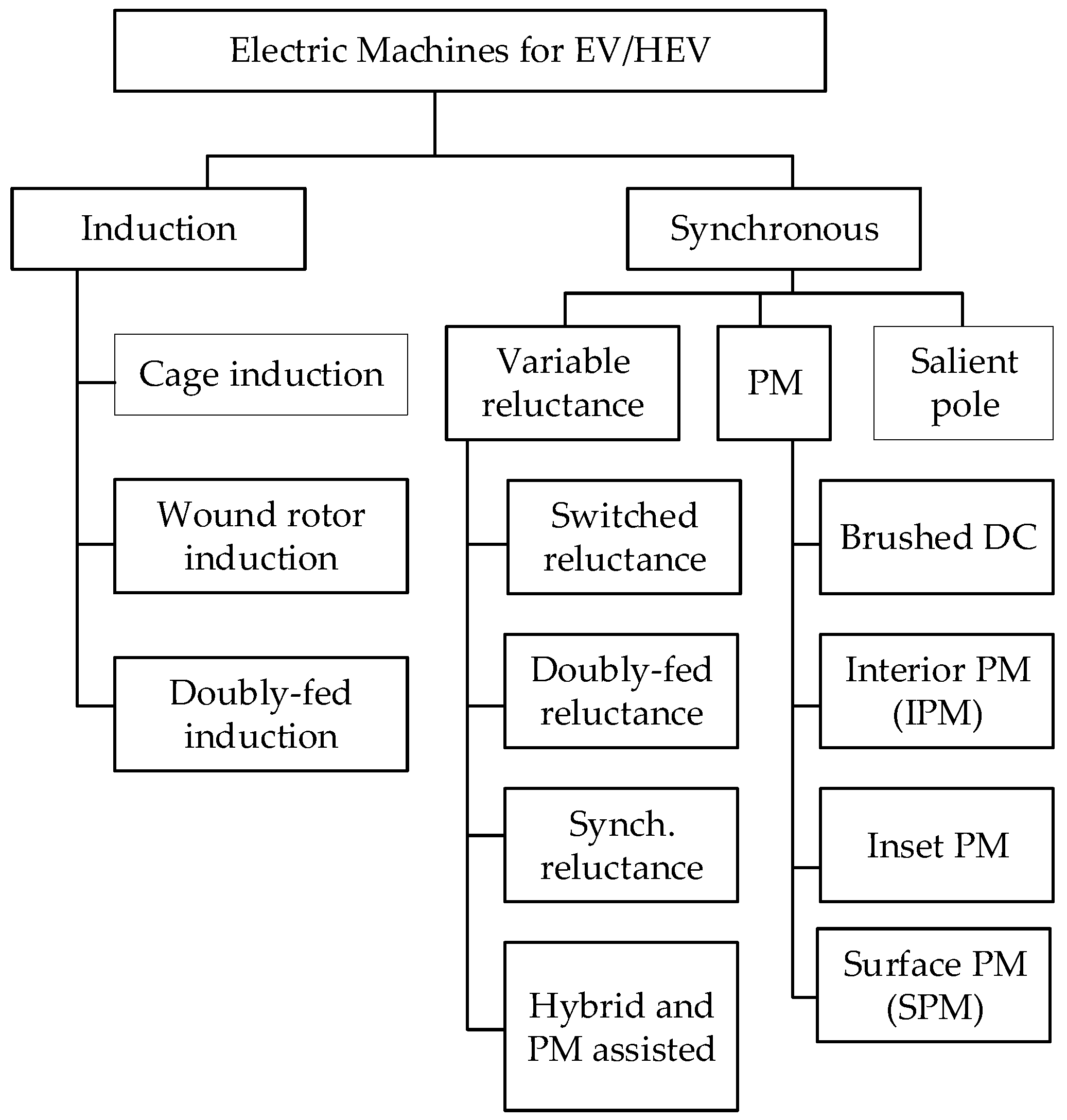
2. Basic Types of Electric Machines

Electric machines in EVs are expected to be high efficiency, have high rated torque, high starting torque, wide speed range, high overload capacity, high power at cruising speeds, high constant power speed range (CPSR), high specific power and power density, fast dynamic response, good flux weakening capability at high speeds, high reliability and good fault tolerance characteristics. These important requirements are essential regardless of machine type. However, the topology and principle of operation of the machine dictates the design and control measures that are needed to meet these requirements. The machine that meets all these requirements must be at a cost that is acceptable.
Table 1 shows the specification parameters of recent vehicles, gleaned from various sources. Even if some insight can be obtained, putting these data side by side, it is difficult to compare these values without putting the vehicle traction drive system architecture and/or hybridization strategy in perspective. Even then, the machines are different in several respects including the fact that some vehicles use two machines while others use one. It is therefore difficult to compare these machines in any meaningful way, however, it is informative to see some trends including moving away from induction machines (IMs) toward the use of permanent magnet (PM) machines for most of the traction applications. However, there are a lot more machine types that can be potentially applied in electric vehicles.
Figure 1 shows the potential motor types and possible choices for EV applications. The basic types of machines used in electric vehicles (EVs) are DC machines, induction machines, permanent magnet synchronous machines, switched reluctance machines and synchronous reluctance machines. In most recent vehicles, three classes of machines have been applied including induction machines, synchronous machines, permanent magnet machines and reluctance machines. Various configurations of machines have been used or are potential motors to be used, including radial flux and axial flux permanent magnet synchronous machines, induction machines, switched reluctance machines and flux switching machines.
The machine choices in Figure 1 are quite wide, and it is likely that innovative designs are under investigation in research labs. Under the induction machine category, doubly-fed, wound rotor induction motors are currently not applied in any vehicle applications. While doubly-fed induction machines have been a standard machine applied in wind generation, these are not likely to meet the power density and efficiency requirements for current vehicular application needs. Under the synchronous-machines category, salient pole machines are typically used in power generation, and likewise not currently used for commercial EVs, though they have been investigated in the past for automotive applications [20,33,34].
Wound-field synchronous machines have been identified as potential candidates with the high specific power required for electric propulsion [35]. Machine topologies such as the doubly-fed reluctance is one of the many class of machines that are being investigated for various potential applications, but are currently not used in any vehicles.

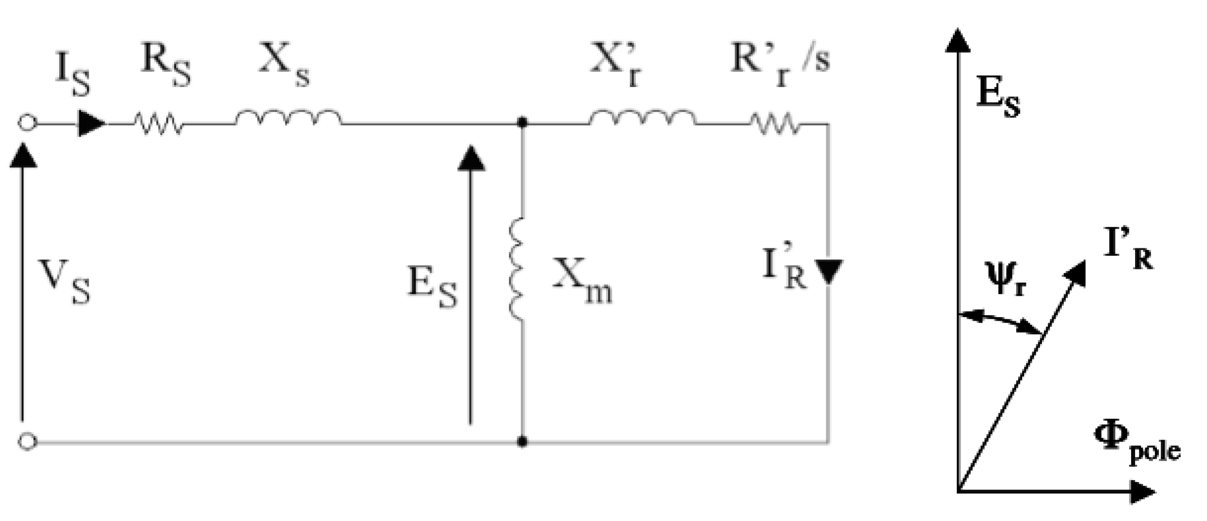
2.1. Induction Machines

Squirrel cage induction machines have a rich history as the most widely used machines in industry. With their simplicity, low cost and ruggedness, they are a good candidate for most applications including traction. Other key advantages of these machines include high peak torque, good dynamic response, and very low maintenance requirement in all aspects of operation. The machines are typically operated with a standard 2-level vector-controlled drive, which enables a wide speed range of operations, for example as shown in Figure 2. These machines are characterized by three distinct operational regimes, namely constant torque, constant power, and reduced power regions, that are determined by the design choices that are made with respect to the machine design and power electronic control.
The induction machine technology is relatively old comprising a stator with distributed winding and either a die-cast squirrel cage rotor or, less frequently, a wound rotor. An example of induction machine components are shown in Figure 3. The technology has been used for industrial applications with remarkable success. Notable automotive applications include the GM EV-1 vehicle, and earlier models from the Tesla Motor Corporation. The development of techniques to economically die-cast copper rotors in the late 1990s gave these machines a significant boost. In contrast to aluminum die-cast rotors, the higher electrical conductivity of copper (higher by nearly 60% when compared to Aluminum) leads to significant decreases in overall motor losses, estimated to about 15–20% [36]. It is, however, necessary to properly design and optimize rotor slots in order to derive the benefits of the conductor properties. By the time Tesla’s Roadster (and subsequently Models S and X) were released, commercial die-casting of copper rotors had been available for a decade with two major motor manufacturers offering commercial copper rotor motors with many lessons learned.
The die-cast copper rotor technology can be considered a mature technology that can provide a path to high efficiency machines due to reduced losses in the rotor, and these reduced losses in the rotor can further result in reduced need for cooling. The technical tradeoff is that copper is heavier than aluminum and adds to machine weight. Therefore, copper rotor technology per se does not provide a solution to the inherent challenges of the induction machine as a vehicular technology, especially given the increasing demands on efficiency and power density.
The electromagnetic torque of the induction machine from the simplified equivalent circuit (Figure 4) can be written as:
T = m p V s 2 R r s 2 π f s [ ( R s + R r s ) 2 + X k 2 ]
where T is the machine torque, m is the number of phases, p is the number of pole pairs, Vs. is phase voltage, fs is supply frequency, s is the slip, Rr is rotor resistance, Rs is stator resistance, and Xk is the equivalent short circuit reactance of the rotor and stator. From a magnetic perspective that emphasizes the importance of the slot area and flux densities, the torque can be approximated as in Equation (2) [39],
T ( 1 B g k i r o n   B t ) × B g × σ × h s × R g 2 × L
where Bt is tooth flux density, Bg is air gap flux density, L is active length, and Rg is the mean radius of the machine airgap, hs is tooth height, σ is current density, kiron is the lamination stacking factor. Expression (2) emphasizes the fact that a high flux density in the airgap, and high rotor current density are both important for high electromagnetic torque. The air gap flux density is generally limited by the tooth saturation. The maximum torque is directly proportional to the square of the voltage (or square of the flux) and inversely proportional to the supply frequency. This relationship explains the well-known torque envelope of the machine as shown in Figure 2. The general theoretical considerations, requirements and trade-off considerations for the design of induction machines are presented in [39]. For traction applications where these machines are normally used with an inverter, some additional requirements are introduced, while some design requirements are relaxed. A key benefit is that unlike in a design for an industrial machine, design restrictions on starting current are not an issue, a high starting torque can be obtained, and a reasonable constant power speed range can be obtained with careful choice of the voltage and frequency [18].

2.2. Permanent Magnet Synchronous Machines

The majority of the machines currently used in vehicles are permanent magnet machines. The increasing requirements of high efficiency, high specific power, and high power density caused a shift toward permanent magnet machines, such as the departure from the traditional induction machines previously used in the Tesla Model S toward permanent magnet-based technologies in the Tesla Model 3, as shown in Figure 5c.
There are various topologies and classifications of permanent magnet machines, but the rotor design serves as a basic feature of classification of permanent magnet machines into two broad categories: surface permanent magnet (SPM) and interior permanent magnet machines (IPM). The rotor design influences several important features of the machine, including the constant power speed range. The SPM machines have a relatively simple design/structure but the magnet being located on the surface of the rotor results in a larger airgap that impacts the performance of the machine, particularly its CPSR. Even though SPM machines can be designed with concentrated windings to achieve significantly improved CPSR, their application in automotive is now quite limited, especially in the light of the move toward high torque and high power density machines with reduced magnet content.
The electromagnetic torque equation of the permanent magnet synchronous machine in the d-q reference frame can be expressed as:
T = 3 2 p × [ λ p m i q ( L q L d ) × i d i q ]
where p is the number of pole pairs, λpm is the permanent magnet flux, id and iq are the d-axis and q-axis currents, and Ld and Lq are inductances. The trend has been focused on measures to increase the flux linkage due to the magnets and thereby the magnet torque component (first term in bracket) as well as increasing the saliency between the d- and q- axes in order to increase the reluctance component of the torque, which is the second term of the bracket. Increasing the magnet torque comes with increased iron losses at no load conditions and has implications for flux weakening operation. By designing a machine with significant reluctance torque in lieu of magnet torque, the permanent magnet volume in the machine can be reduced while the machine is still capable of achieving high constant power speed range. From Equation (3), the reluctance torque can mathematically be maximized by increasing Lq (through increased q-axis permeance) and reducing Ld (permeance along d-axis) to a level that is consistent with the desired flux weakening capability as Ld directly affects the machine’s characteristic current. In order to increase the flux linkage, it is important to reduce flux leakage and measures must be adopted in that regard as well, with innovative design of flux barriers. However, increasing the number of flux barriers impairs the mechanical integrity of the rotor. It is evident from Equation (3), that the surface permanent magnet machines (SPM) have no reluctance torque component since the stator winding inductances Ld and Lq are the same. For automotive traction, it seems that the IPM machine and its variations will be favored over the SPM machine in the foreseeable future due to the important advantages offered by the reluctance torque. The reluctance torque afforded by the IPM design, also means that the rotor design is critical to machine performance. The rotor design of these machines has progressed from basic flat magnets through various configurations of U-, V-, W-shaped magnets and double V-shaped and several others, including variations in magnet sizes from pole to pole. Figure 5 shows rotor design of IPM machines of recent production vehicles, where it can be noted for example, the progression of the Toyota Prius from a single V in 2010 to a double V in 2017. Correspondingly, with double V and multiple Vs, the magnet volume per Nm of torque has also progressively increased. For comparison, [25] estimates that single V motors use less than 4 g/Nm versus 4 to 7 g/Nm for double Vs. Since nearly all the traction machines in surveyed in this paper use high strength rare earth magnets, this upward trend of magnet consumption is quite disconcerting.
In terms of winding design, the IPM stators for traction machines are wound with concentrated windings or distributed windings [18,19,20,21,22,23,24,25]. Typical examples of recent vehicle stators are shown in Figure 6. The concentrated windings have shorter end windings leading to lower copper loss than the distributed windings, with the latter typically having longer end turns and consequent higher Joule losses. The distributed windings can be random wound with strands or bar wound in the hairpin fashion. In recent production vehicles such as the Chevy Spark, Chevy Bolt, and Toyota Prius 2017, the hair pin design was used, and it is becoming the popular trend. This winding design has been reported to exhibit higher slot fill, reduced end turn length, improved thermal performance and lending itself to a highly automated manufacturing process, compared to the random wound [40].
A type of permanent magnet machine that is increasingly being critically touted is the axial flux machine (AxFM). The AxFMs have desirable characteristics for traction applications such as high power density, high efficiency, compact and modular structure, low weight and high fault tolerance. These characteristics are possible because their structure trades length for diameter and allows to take advantage of torque production on multiple surfaces, with shorter current paths in the machine. Commercial AxFMs in the ~100–260 kW rating have been reported with specific power density of ~5 kW/kg and most of the drivetrains where the motor is buried inside a wheel are based on AxFM, thus this topology is well suited for in-wheel applications.

2.3. Reluctance Machines

Two important machine topologies that operate on the reluctance principle to produce torque are the synchronous reluctance (SynRM) machine and switched reluctance machine (SRM). Both machines have simple construction of a rotor composed of only thin steel laminations with no windings or magnets, the difference between the rotors being that SRM has salient pole construction while the SynRM is typically non-salient, even though it can be designed with saliency. Figure 7 shows the evolution of the SynRM over the years since its invention in the 1920s [41]. Another difference between the construction of the machines is that the stator of the SRM is salient and wound with concentrated coils around each pole, while that of the SynRM typically has a distributed winding.
SynRMs are appealing in terms of their robustness, high efficiency, low torque ripple and simplicity (low cost) of control. These machines have only recently been commercially available for industrial applications as they are seen as a great alternative to variable speed-controlled induction machines. However, SynRMs have a disadvantage with low power factor which affects their operational performance and the power converter sizing. With respect to automotive applications, SynRMs have been investigated for traction drive systems in [27,28], with some recent prototypes built and tested for these applications [42]. For traction drives, SynRMs have relatively low CPSR.
The torque T, and power factor, cosφ, of the SynRM is given by Equations (4) and (5), where Ld and Lq are d- and q-axis inductances respectively, id and iq are d- and q-axis currents respectively and ξ is the saliency ratio, defined here as Ld/Lq. As shown, both the electromagnetic torque and power factor are dependent on the saliency ratio and in order to improve machine performance, they must be designed with a high saliency ratio, ξ , which is a ratio of maximum inductance to minimum inductance as a result of the differences in the permeance along the d-axis and the q-axis. This explains why much of the development history of these machines has been focused on increasing the saliency ratio, for the maximizing the torque as well as the improvement of the power factor. An improved power factor also improves the sizing of the power converter. In recent times, it has been the practice to insert permanent magnets into the flux barrier of the rotor, creating permanent magnet assisted SynRMs [43,44]. Pellegrino et. al [43] outline several advantages of this design, including the reduction of Ld, improvement of power factor, increase in torque due to the added PM torque.
T = 3 2 p 2 × [ ( L d L q ) × i d i q ]
c o s φ = ξ 1 ξ + 1
The SRM has been around much longer than the SynRM, but its proliferation has not been commensurate with a machine that was developed in 1838. This is partly due to operational issues including acoustic noise, high torque ripple, and significant complexity and costs in the controls. SRMs are now increasingly being considered for automotive applications while efforts are on-going to improve their performance. These machines can achieve high CPSR and high efficiency but it seems that the noise and torque ripple continue to be a major barrier to application. For EVs low torque ripple is important, particularly in EV configurations where the electric motor is the main propulsion device. During the last several years, there has been significant research toward low torque ripple designs including elimination through the design of the power electronic controls.
Different directions aimed at increasing the performance and power density of the SRM have been pursued, including the use of double stator and double-sided topologies. For further improvement, the insertion of magnets into the stator poles was also implemented, giving rise to a new class of machines that are being actively researched.
SRMs have been proposed for traction drives and it has been reported in industry publications that some automakers were using or planning to use SRMs in their drivetrains. Traction prototypes have been developed in [29,42]. Figure 8 show an SRM that was developed to match performance of an IPM machine used in the Toyota Prius. Test results were presented in the paper to demonstrate that the SRM machine can compete with rare-earth traction machine alternatives. There is currently a growing need for machines without magnet content and SRM may be a strong contender for candidate motors. These machines are currently also applied in heavy equipment and trucks and it is expected it is likely that their transition into light vehicles could come sooner rather than later.

3. Recent and Projected Trends in Electric Machines in Electric Vehicles

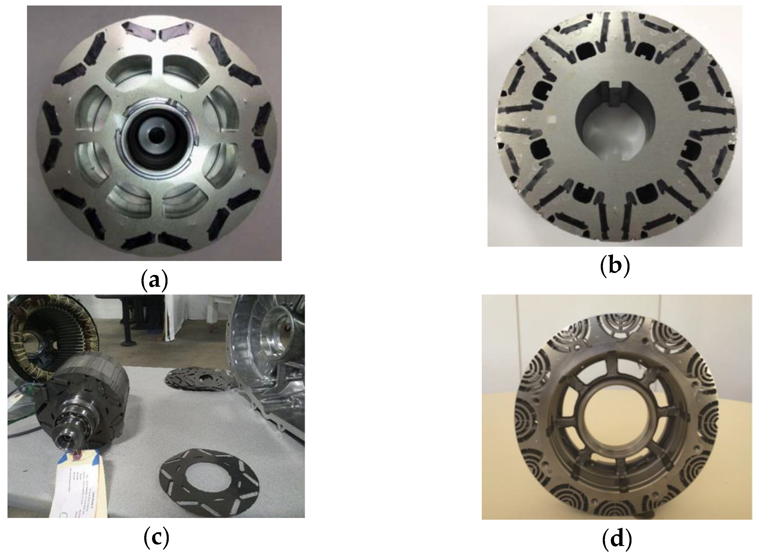
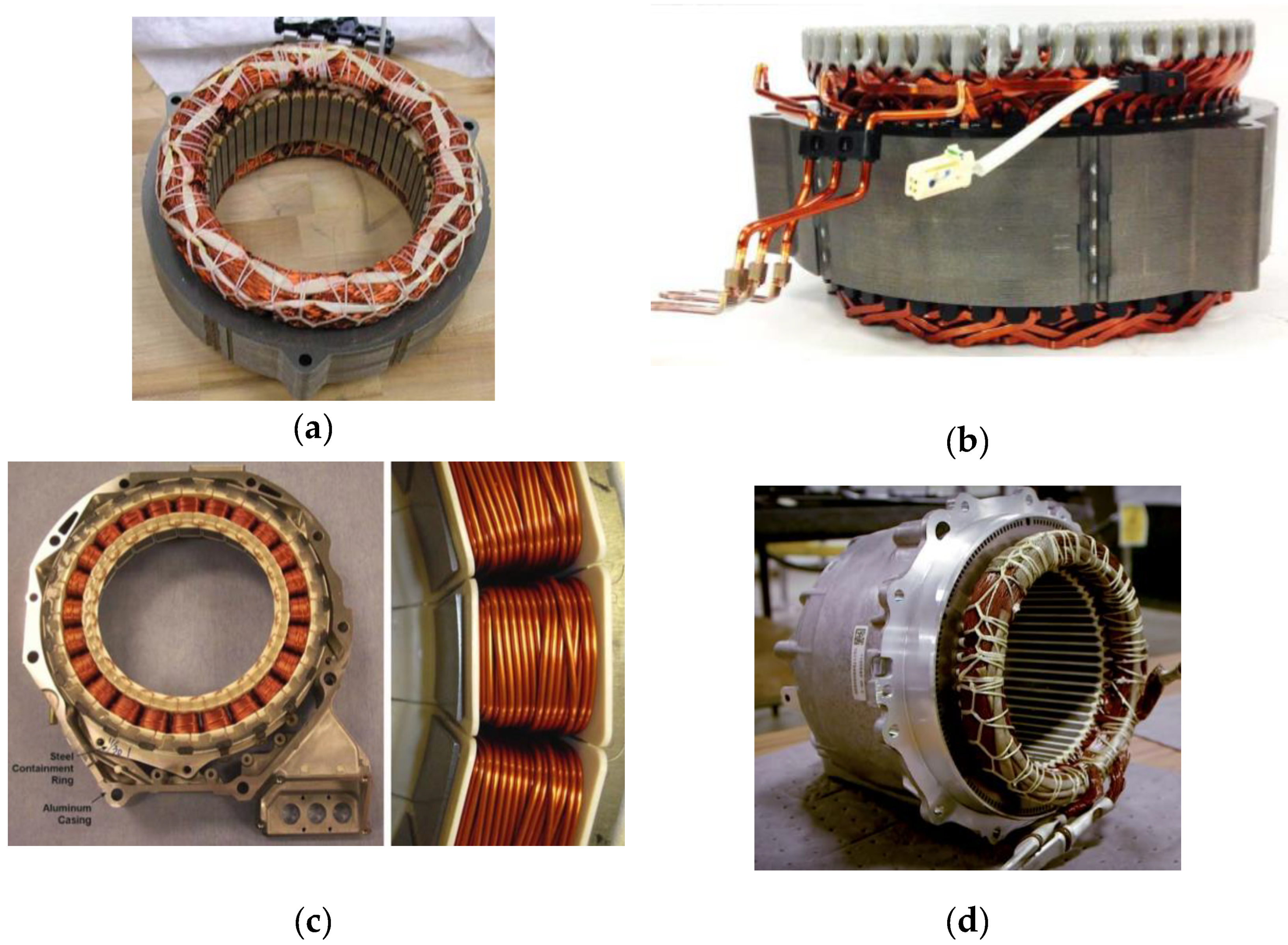
3.1. IPM Machines with Rare-Earth Magnets

The capability of motors employing heavy rare-earth content to meet key performance metrics required of traction motors is not in doubt and most of these machines have been IPM machines with rare earth magnets [45,46,47]. The ability of the IPM machine to develop permanent magnet torque and reluctance torque and to achieve a wide CPSR operation has dramatically increased their appeal for traction drive systems. IPM machines can be designed to develop reluctance torque in the 40–50% range or even higher [25,43]. This attractive feature has made IPM machines the machine of choice for these applications and this trend will continue. One would have thought that with this additional possibility of extracting high reluctance torque, the magnet use in these machines would have stabilized over the years, especially given that the cost of magnets comprise approximately 20–30% of the cost of the motor and manufacturers would be interested in reducing the cost of the motor. However, it was reported in [25] that magnet use has not decreased and may have in fact increased over the years.

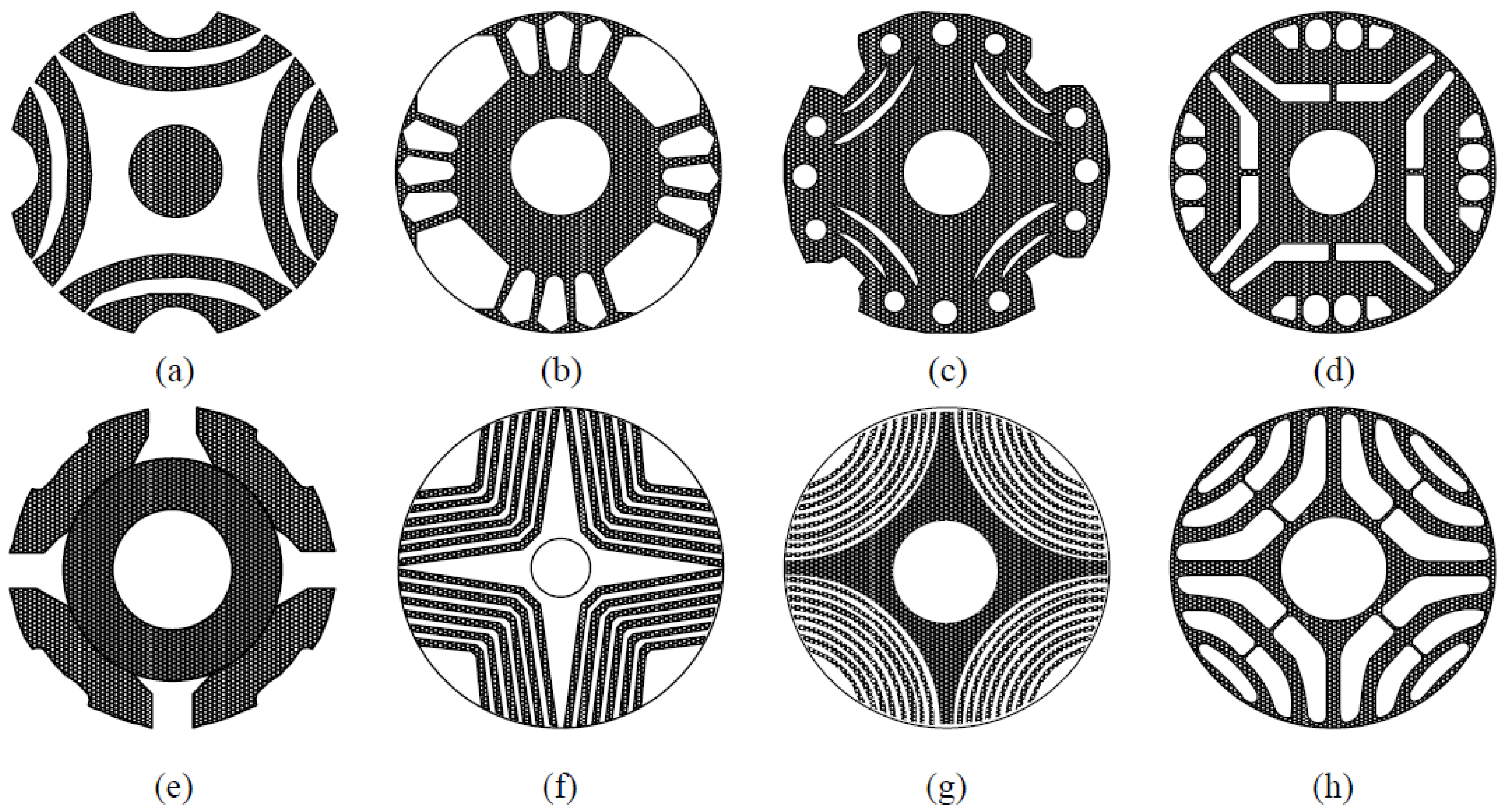
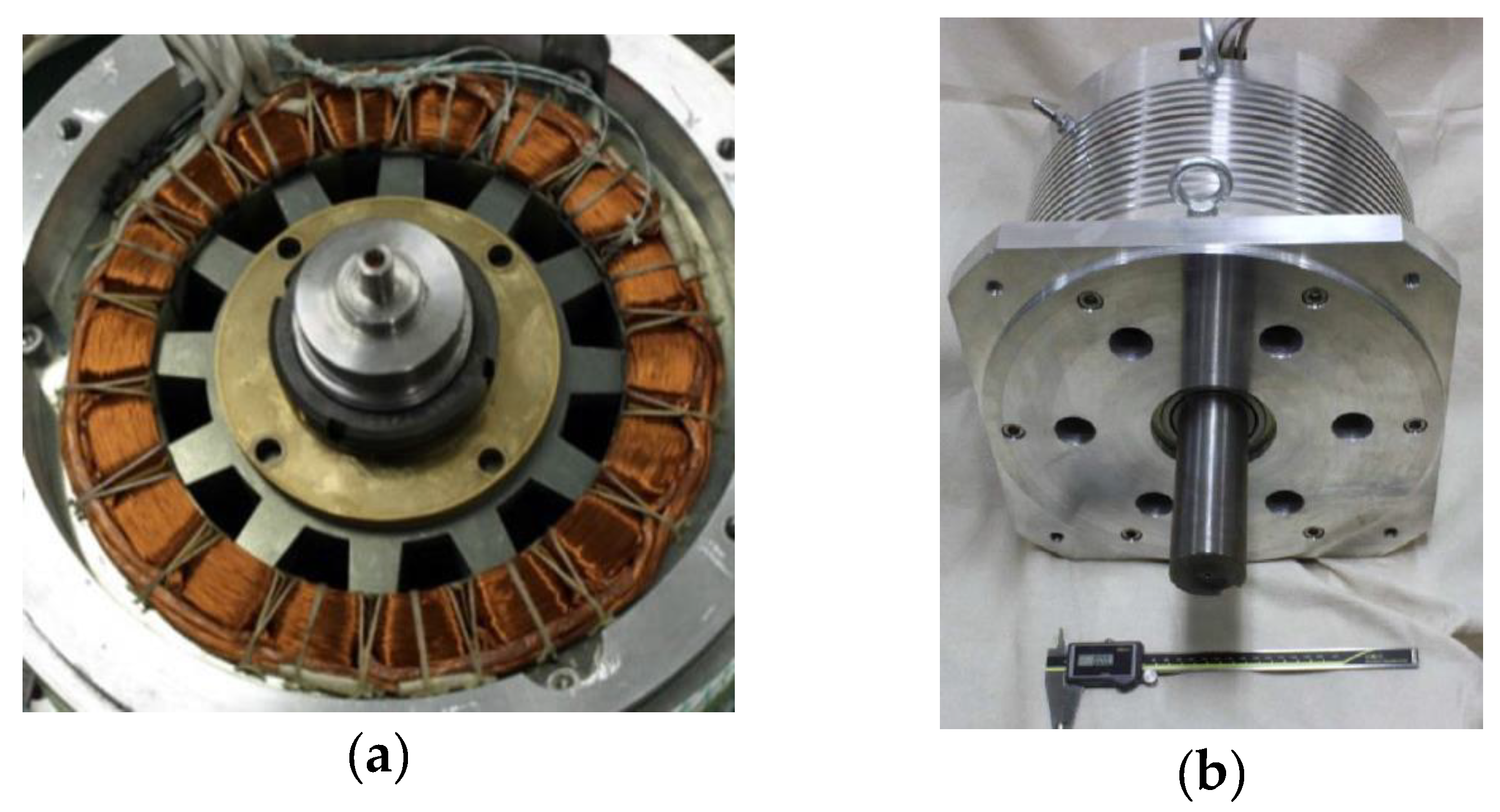
3.2. Traction Machines without Rare-Earth Magnets

A major trend in the design of machines for EVs is the parallel efforts toward non-rare earth machine alternatives. By eliminating the rare-earth magnets, not only is motor cost reduction improved, but also the dependence on this critical material is removed. Induction machines have had a good shot at meeting this need but the increasing demands on high specific power and power density requirements are eliminating induction machines as viable options. Two other important machine topologies, discussed in Section 2.3, that eliminate magnets on the rotor are the synchronous reluctance (SynRM) machine and switched reluctance machine (SRM). Both machines have simple construction of a rotor composed of only thin steel laminations. Again, the SRM has significant noise issues and high torque ripple and vibration, as well as significant complexity and costs in the controls. SynRMs are also appealing in terms of their robustness, high efficiency, low torque ripple and simplicity (low cost) of control but have major disadvantage such as lower power factor which impacts converter sizing and cost and more importantly, they have a limited CPSR. These disadvantages can be abated by significantly improved saliency ratios. If properly designed, SynRM with no magnets can be a very attractive low-cost machine from both motor and inverter perspective. It appears that with significant research, SynRM and SRMs can provide a path to obtain high performance traction machines without rare earth content. The research to improve SRM and SynRM may be a worthwhile pursuit for non-rare-earth or reduced rare-earth drivetrains [22].

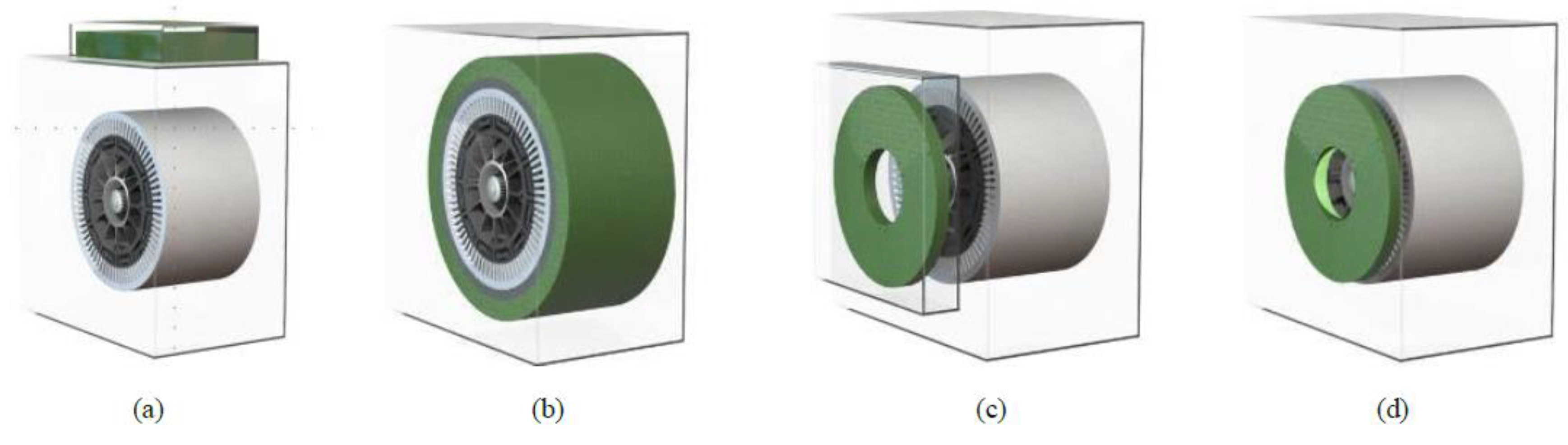
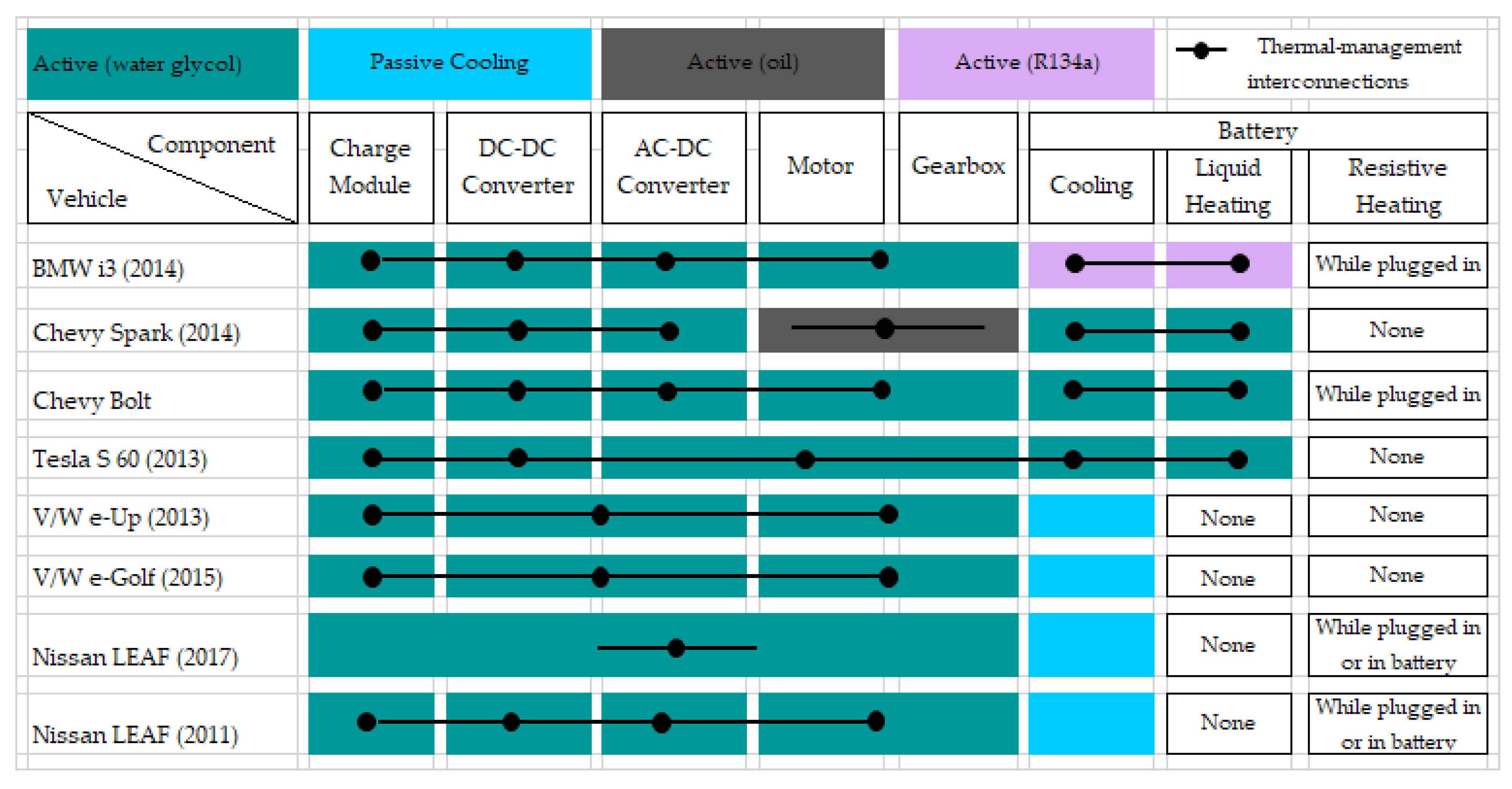
3.3. Machine Integration and Thermal Management Systems

Machine and power electronics integration is another increasing trend that will continue. As space requirements for vehicular comfort increase, powertrain devices must become more compact, and innovative integration techniques consequently become more important. The idea of physically integrating the electric machine and power electronic drive into one enclosure (package) does not only provide benefits of compactness or reduced size but also ease of installation, reduced number of parts, shortened cable runs and busbars, all of which could translate into desirable technical benefits including reduced electromagnetic interference, reduced voltage overshoots on motor drive terminal as well as significant cost savings. It is estimated that integrated motor and power electronics can achieve 10–20% improvement of power density and 30–40% reduction in manufacturing and installation costs [26,48,49]. However, the co-location of electric machine and power electronics in the same package poses significant challenges for the combined system. One major problem is the compounded thermal management issues of the system. Another issue is that, a motor is prone to vibration but more tolerant to vibration and harshness than electronic boards that are fragile and less tolerant to vibration. Therefore, combining these two components in one package poses a problem. These problems have been the subject of research with the view to developing practical and innovative solutions that harness the advantages of integration while minimizing the problems of the system.
Chowdhury et. al [26] summarized the four major types of integration techniques that are found in literature and these are captured in Figure 9. The techniques comprise radial and axial mounting approaches which primarily involve mounting the power electronics on either the motor housing as in Figure 9a,c, or on the stator (Figure 9b,d). In Figure 9a, the power electronic inverter is mounted on top of the housing of the motor while the same component is mounted on the end shield of the motor in Figure 9c. In Figure 9b the power electronics is mounted on the periphery of the motor stator, while it is mounted on the end of the stator in Figure 9d. Each of these mounting variants have advantages and disadvantages that are provided in [26]. For example, the more common approach shown in Figure 9a is simple to implement but has limited capability of achieving high power density. In this design, the inverter package is placed on the housing of the motor or in some variations of the same concept, on the side of the housing. Furthermore, a shared or separate cooling system for the motor and drive can be used. In some cases, the cooling system is separate, leading to sub optimal utilization of system volume. The other designs where the power electronics is fitted to the stator periphery yield a better integration but due to stator curvature, they do not easily lend a flat surface to mount electronics components.
The integration strategy and the level of integration will be dependent on the configuration of the vehicle, including number of motors and axles. In general, vehicles with a front motor may be integrated differently than those with rear motor or both and even then, the arrangement of the motor drive will depend on the size of the vehicle, battery footprint and other factors. Figure 10 shows some recent examples of integrated motor and power electronics in two production vehicles and the integration strategies of these two vehicles are consistent with their features. For example, compact front axle vehicles would most likely opt for radial housing mount and it is very much what is applied in such vehicles such as the Chevy Bolt and Spark, Nissan Leaf and Toyota Prius. A typical example of the radial housing implementation is in the Chevy Volt [50]. The Tesla vehicles that feature two axle motors and rear motor configurations have leaned toward the axial end plate mount in these vehicles, creating a longitudinal instead of vertical arrangement. In-wheel type integrated motor drives are most likely to be configured as in Figure 9b or Figure 9d. In general, it is expected that tighter and tighter integration will be pursued due to the important advantages mentioned previously. Tight integration will become even common as drivetrains converge toward mass market skateboard platforms.
For continued improvement in power density and specific power of vehicular traction drive systems, advanced thermal management systems are required. A comprehensive overview of the cooling strategies applied traction motors and their analyses, and the computation methods are reviewed in [51]. The paper provided a summary of the convection methods applied in automotive traction motors with their advantages and disadvantages and requirements for optimizing cooling performance for the respective methods discussed. The papers also highlighted the cooling methods used in the traction motors of recent vehicles. Of the nine traction motors surveyed in the paper, nine used mainly, housing jacket cooling with water or oil in addition to other forms of cooling. This is an indication of the increasing importance for advanced cooling systems, particularly, as machine power requirements continue to increase and vehicle range continues to increase. The recent trends of tight motor drive integration also make sense for the application of advanced thermal management systems that can simultaneously provide the needed cooling of motor drive components as well as other power train and vehicle components. Figure 11 shows the thermal management systems and interconnections that are applied for cooling power train components and batteries in recent vehicles [52]. The variations in these systems are evident but not surprising. First off, active cooling with water glycol is prevalent for all drive trains and from all manufacturers, except for the Chevy Spark that uses active oil cooling. Secondly, we see different levels of integration and correspondingly different interconnections between components. For example, in the Tesla the cooling is interconnected between all drive train components and the battery. We also see a tighter integration in the second generation of the Nissan Leaf, compared to the first. Considering the examples provided by the Tesla and the 2017 Leaf, it would be reasonable to expect that most of these vehicles will follow a tighter integration with a common thermal management system that interconnects all drivetrain components and the battery.

4. Conclusions

This paper presents an overview of notable trends toward high specific power density and high-power density machines used for traction in recent vehicles with a focus on current technologies and the trends that are likely to be pursued in the near future. The major directions likely include the development of permanent magnet machines with high specific power and high power density, since the majority of the traction machines are currently permanent magnet machines. This trend is expected to continue into the future, and, in particular, the development of permanent magnet machines developing increased amounts of reluctance torque seems a natural area of activity.
The search for non-rare earth alternative traction machines is gaining significant interest and is likely to continue into the future. With regard to the latter, synchronous reluctance and permanent magnet assisted reluctance machines as well as switched reluctance machines have been favored by many researchers. Although this paper did not discuss the power converter components, it is becoming a trend to integrate the machines and drives and the thermal management system in one package, and to transition from Si-based to SiC-based devices, and these trends obviously will impact the choices made in machine design. It is also expected that, as a future trend, most vehicles will follow a tighter integration to a common thermal management system that interconnects all drivetrain components and the battery.

Author Contributions

Conceptualization, E.A. and A.v.J.; data curation, E.A.; writing—original draft preparation, E.A.; writing—review and editing, E.A., A.v.J. and A.Y. All authors have read and agreed to the published version of the manuscript.

Funding

This research received no external funding.

Conflicts of Interest

The authors declare no conflict of interest.

References

  1. Husain, I. Electric and Hybrid Vehicles Design Fundamentals, 2nd ed.; CRC Press: Boca Raton, FL, USA, 2011. [Google Scholar]
  2. Palmquist, M. The Auto Industry’s Big Bailout Bounce—Strategy+Business. Available online: https://www.strategy-business.com/article/re00245?gko=21e83 (accessed on 9 February 2020).
  3. EEI, Electric Vehicle Sales Facts and Figures. Available online: https://www.eei.org/issuesandpolicy/electrictransportation/Documents/FINAL_EV_Sales_Update_April2019.pdf (accessed on 9 February 2020).
  4. Oak Ridge National Laboratory. Available online: https://www.ornl.gov/ (accessed on 9 February 2020).
  5. Miller, J.M. Oak Ridge National Laboratory Annual Progress Report for the Power Electronics and Electric Motors Program. 2013. Available online: https://info.ornl.gov/sites/publications/files/Pub46377.pdf (accessed on 9 February 2020).
  6. Ozpineci, B. Oak Ridge National Laboratory Annual Progress Report for the Power Electronics and Electric Motors Program. 2014. Available online: https://info.ornl.gov/sites/publications/files/Pub52422.pdf (accessed on 9 February 2020).
  7. Burress, T.A.; Campbell, S.L.; Coomer, C.L.; Ayers, C.W.; Wereszczak, A.A.; Cunningham, J.P.; Marlino, L.D.; Seiber, L.E.; Lin, H.T. Evaluation of The 2010 Toyota Prius Hybrid Synergy Drive System. Available online: https://info.ornl.gov/sites/publications/files/Pub26762.pdf (accessed on 9 February 2020).
  8. Burress, T. Electrical Performance, Reliability Analysis, and Characterization. Available online: https://www.energy.gov/sites/prod/files/2017/06/f34/edt087_burress_2017_o.pdf (accessed on 9 February 2020).
  9. Staunton, R.H.; Burress, T.A.; Marlino, L.D. Evaluation of 2005 Honda Accord Hybrid Electric Drive System. Available online: https://www.osti.gov/servlets/purl/891260 (accessed on 9 February 2020).
  10. Burress, T.A.; Campbell, S.L.; Coomer, C.; Ayers, C.W.; Wereszczak, A.A.; Cunningham, J.P.; Marlino, L.D.; Seiber, L.E.; Lin, H.-T. Evaluation of the 2010 Toyota Prius Hybrid Synergy Drive System. Available online: https://www.osti.gov/biblio/1007833-evaluation-toyota-prius-hybrid-synergy-drive-system (accessed on 9 February 2020).
  11. Burress, T. Benchmarking of Competitive Technologies. Available online: https://www.energy.gov/sites/prod/files/2014/03/f10/ape006_burress_2011_o.pdf (accessed on 9 February 2020).
  12. Tesla Model 3 Battery/Motor/Glued Magnets. Available online: https://www.electric-skateboard.builders/t/tesla-model-3-battery-motor-glued-magnets/78764 (accessed on 9 February 2020).
  13. Tesla Model 3 Powertrain Fun. From Carburetors To Carborundum. You’ve Come A Long Way, Baby! Available online: https://cleantechnica.com/2018/05/28/more-tesla-model-3-powertrain-fun-from-carburetors-to-carborundum-youve-come-a-long-way-baby/ (accessed on 9 February 2020).
  14. What Is inside a Tesla Engine? Available online: https://www.youtube.com/watch?v=wvLmBfwmA04 (accessed on 9 February 2020).
  15. Ingineerix. “First Look: Tesla Model 3 Drive Unit”. Available online: https://www.youtube.com/watch?v=m4eQ7nN_Lwo (accessed on 9 February 2020).
  16. Benchmarking Contents: Benchmarking Intelligence at Its Best. Available online: https://portal.a2mac1.com/benchmarking-database/URL (accessed on 17 February 2020).
  17. El-Refaie, A.M. Motors/generators for traction/propulsion applications: A review. IEEE Veh. Technol. Mag. 2013, 8, 90–99. [Google Scholar] [CrossRef]
  18. Zhu, Z.Q.; Howe, D. Electrical machines and drives for electric, hybrid, and fuel cell vehicles. Proc. IEEE 2007, 95, 746–765. [Google Scholar] [CrossRef]
  19. Un-Noor, F.; Padmanaban, S.; Mihet-Popa, L.; Mollah, M.N.; Hossain, E. A Comprehensive Study of Key Electric Vehicle (EV) Components, Technologies, Challenges, Impacts, and Future Direction of Development. Energies 2017, 10, 1217. [Google Scholar] [CrossRef] [Green Version]
  20. Boldea, I.; Tutelea, L.N.; Parsa, L.; Dorrell, D.G. Automotive Electric Propulsion Systems With Reduced or No Permanent Magnets: An Overview. IEEE Trans. Ind. Electron. 2014, 61, 5696–5711. [Google Scholar] [CrossRef]
  21. Widmer, J.D.; Martin, R.; Kimiabeigi, M. Electric vehicle traction motors without rare earth magnets. Sustain. Mater. Technol. 2015, 3, 7–13. [Google Scholar] [CrossRef] [Green Version]
  22. Jahns, T.M. Getting Rare-Earth Magnets Out of EV Traction Machines: A review of the many approaches being pursued to minimize or eliminate rare-earth magnets from future EV drivetrains. IEEE Electrif. Mag. 2017, 5, 6–18. [Google Scholar] [CrossRef]
  23. Wang, A.; Jia, Y.; Soong, W.L. Comparison of Five Topologies for an Interior Permanent-Magnet Machine for a Hybrid Electric Vehicle. IEEE Trans. Magn. 2011, 47, 3606–3609. [Google Scholar] [CrossRef]
  24. Ibrahim, M.N.; Sergeant, P.; Rashad, E.M. Rotor design with and without permanent magnets and performance evaluation of synchronous reluctance motors. In Proceedings of the 2016 19th International Conference on Electrical Machines and Systems (ICEMS), Chiba, Japan, 13–16 November 2016; pp. 1–7. [Google Scholar]
  25. Lequesne, B. Electric Machines for Automotive Propulsion: History and Future, Keynote Presentation, IEEE ITEC-AP 2019, May 2019. Available online: www.emotorseng.com (accessed on 9 February 2020).
  26. Chowdhury, S.; Gurpinar, E.; Su, G.J.; Raminosoa, T.; Burress, T.A.; Ozpineci, B. Enabling Technologies for Compact Integrated Electric Drives for Automotive Traction Applications. In Proceedings of the 2019 IEEE ITEC, Detroit MI, USA, 19–21 June 2019. [Google Scholar]
  27. Ban, B.; Stipetić, S.; Klanac, M. Synchronous Reluctance Machines: Theory, Design and the Potential Use in Traction Applications. In Proceedings of the 2019 EDPE Conference, The High Tatras, Slovakia, 24–26 September 2019. [Google Scholar]
  28. Reddy, P.B.; El-Refaie, A.M.; Galioto, S.; Alexander, J.P. Design of Synchronous Reluctance Motor Utilizing Dual-Phase Material for Traction Applications. IEEE Trans. Ind. Appl. 2017, 53, 1948–1957. [Google Scholar] [CrossRef]
  29. Chiba, A.; Takano, Y.; Takeno, M.; Imakawa, T.; Hoshi, N.; Takemoto, M.; Ogasawara, S. Torque Density and Efficiency Improvements of a Switched Reluctance Motor Without Rare-Earth Material for Hybrid Vehicles. IEEE Trans. Ind. Appl. 2011, 47, 1240–1246. [Google Scholar] [CrossRef]
  30. Chiba, A.; Kiyota, K.; Hoshi, N.; Takemoto, M.; Ogasawara, S. Development of a Rare-Earth-Free SR Motor with High Torque Density for Hybrid Vehicles. IEEE Trans. Energy Convers. 2014, 30, 175–182. [Google Scholar] [CrossRef]
  31. Takeno, M.; Chiba, A.; Hoshi, N.; Ogasawara, S.; Takemoto, M.; Rahman, M.A. Test Results and Torque Improvement of the 50-kW Switched Reluctance Motor Designed for Hybrid Electric Vehicles. IEEE Trans. Ind. Appl. 2012, 48, 1327–1334. [Google Scholar] [CrossRef]
  32. El-Refaie, A.; Osama, M. High Specific Power Electrical Machines: A System Perspective. China Electrotech. Soc. Trans. Electr. Mach. Syst. 2019, 3, 88–93. [Google Scholar] [CrossRef]
  33. Dorrell, D.G. Are wound-rotor synchronous motors suitable for use in high efficiency torque-dense automotive drives? Proc. IEEE IECON 2012. [Google Scholar] [CrossRef]
  34. Rossi, C.; Casadei, D.; Pilati, A.; Marano, M. Wound Rotor Salient Pole Synchronous Machine Drive for Electric Traction. In Proceedings of the Conference Record of the 2006 IEEE Industry Applications Conference Forty-First IAS Annual Meeting, Tampa, FL, USA, 8–12 October 2006. [Google Scholar]
  35. Zhang, X.; Bowman, C.L.; Haran, K.S.; O’Connell, T.C. Large electric machines for aircraft electric propulsion. IET Electr. Power Appl. 2018, 12, 767–779. [Google Scholar] [CrossRef]
  36. Cowie, J.G.; Brender, D.T. Die-cast Copper Rotors for improved motor performance. In Proceedings of the 2003 IEEE Annual Pulp and Paper Industry Technical Conference, Charleston, SC, USA, 16–20 June 2003. [Google Scholar]
  37. Available online: https://commons.wikimedia.org/wiki/File:Tesla_Model_S_motor_cutout.jpg (accessed on 9 February 2020).
  38. Available online: http://www.favi.com/en/electric-mobility/ (accessed on 9 February 2020).
  39. Agamloh, E.; Cavagnino, A. High efficiency design of induction machines for industrial applications. In Proceedings of the IEEE Workshop on Electrical Machine Design, Control and Diagnosis, Paris, France, 11–12 March 2013. [Google Scholar]
  40. England, M.; Ponick, B. Automated design of hairpin windings as tabular winding diagrams. Elektrotech. Informationstech. 2019, 136, 159–167. [Google Scholar] [CrossRef]
  41. Kabir, M.A. High Performance Reluctance Motor Drives with Three-Phase Standard Inverter. Ph.D. Thesis, North Carolina State University, Raleigh, NC, USA, 2017. [Google Scholar]
  42. Grace, K.; Galioto, S.; Bodla, K.; El-Refaie, A.M. Design and Testing of a Carbon-Fiber-Wrapped Synchronous Reluctance Traction Motor. IEEE Trans. Ind. Appl. 2018, 54, 4207–4217. [Google Scholar] [CrossRef]
  43. Pellegrino, G.; Jahns, T.M.; Bianchi, N.; Soong, W.L.; Cupertino, F. The Rediscovery of Synchronous Reluctance and Ferrite Permanent Magnet Motors Tutorial Course Notes; Springer: Basel, Switzerland, 2016. [Google Scholar]
  44. Bianchi, N.; Fornasiero, E.; Ferrari, M.; Castiello, M. Experimental Comparison of PM-Assisted Synchronous Reluctance Motors. IEEE Trans. Ind. Appl. 2015, 52, 163–171. [Google Scholar] [CrossRef]
  45. Momen, F.; Rahman, K.; Son, Y.; Savagian, P. Electrical propulsion system design of Chevrolet Bolt battery electric vehicle. In Proceedings of the 2016 IEEE Energy Conversion Congress and Exposition (ECCE), Milwaukee, WI, USA, 18–22 September 2016; pp. 1–8. [Google Scholar]
  46. Momen, F.; Rahman, K.M.; Son, Y.; Savagian, P. Electric Motor Design of General Motors’ Chevrolet Bolt Electric Vehicle. SAE Int. J. Altern. Powertrains 2016, 5, 286–293. [Google Scholar] [CrossRef]
  47. Jurkovic, S.; Rahman, K.M.; Savagian, P. Design, Optimization and Development of Electric Machine for Traction Application in GM Battery Electric Vehicle. In Proceedings of the IEEE Electric Machines and Drives Conference, Coeur d’Alene, ID, USA, 10–13 May 2015. [Google Scholar]
  48. Throne, D.; Martinez, F.; Marguire, R.; Arens, D. Integrated Motor/Drive Technology with Rockwell Connectivity. Available online: http://www.cmafh.com/enewsletter/PDFs/IntegratedMotorDrives.pdf (accessed on 3 April 2020).
  49. Abebe, R.; Calzo, G.L.; Vakil, G.; Mecrow, B.; Lambert, S.; Cox, T.; Gerada, C.; Johnson, M.; Cox, T. Integrated motor drives: State of the art and future trends. IET Electr. Power Appl. 2016, 10, 757–771. [Google Scholar] [CrossRef] [Green Version]
  50. The Quintek Group. 2016 Chevy Volt Voltech Propulsion Gen 2. Available online: https://www.youtube.com/watch?v=2yRS-AJ1VQU (accessed on 5 April 2020).
  51. Gai, Y.; Kimiabeigi, M.; Chong, Y.C.; Widmer, J.D.; Deng, X.; Popescu, M.; Goss, J.; Staton, D.; Steven, A.; Steven, A. Cooling of Automotive Traction Motors: Schemes, Examples, and Computation Methods. IEEE Trans. Ind. Electron. 2018, 66, 1681–1692. [Google Scholar] [CrossRef]
  52. Enriquez, M.; Morel, T.; Mouliere, P.-Y.; Schafer, P. Trends in Electric-Vehicle Design. McKinsey and Company. 2017. Available online: https://www.mckinsey.com/industries/automotive-and-assembly/our-insights/trends-in-electric-vehicle-design (accessed on 3 April 2020).
Figure 1. Motor types available for electric vehicles/hybrid electric vehicles (EV/HEVs) (adapted from [20]).
Machines 08 00020 g001
Figure 2. An example torque speed curve of the induction machine operating with a drive.
Machines 08 00020 g002
Figure 3. Induction machine components, showing: (a) Tesla motor cut-out [37], and (b) die-cast copper rotor [38].
Machines 08 00020 g003
Figure 4. The simplified equivalent circuit model of an induction machine [39].
Machines 08 00020 g004
Figure 5. Rotor design of the interior permanent magnet (IPM) machine of production traction motors: (a) 2010 Prius [7] V-shaped rotor; (b) 2017 Prius double U rotor [8]. (c) 2017 Tesla Model 3 IPM V rotor [13], (d) 2016 Chevy Volt IPM rotor [22].
Machines 08 00020 g005
Figure 6. Stator distributed winding design in traction motors for production vehicles: (a) 2010 Prius [7], in 2017 the Prius moved to hairpin distributed winding; (b) Prius 2017 [8], the hairpin design was also used in Bolt and Spark; (c) stator concentrated winding design for production traction machines- Accord 2005 [9]; (d) distributed winding in Tesla Model 3 [12].
Machines 08 00020 g006
Figure 7. Evolution of synchronous reluctance machines (SynRMs) showing different rotor designs [41] (a) the original Kostko rotor; (b) rotor adapted from an induction motor rotor; (c) rotor with multiple barriers; (d) rotor with saturable bridges; (e) segmented rotor; (f) axially laminated V rotor (g) axially laminated U-rotor; (h) modern transverse laminated rotor.
Machines 08 00020 g007
Figure 8. Switched reluctance machine (SRM) proposed for traction application in [30]: (a) rotor inside the stator; (b) assembled motor [29]. This motor was designed to match performance of the 2003 Toyota Prius traction motor.
Machines 08 00020 g008
Figure 9. Motor and inverter integration options [26] (a) radial housing mount; (b) radial stator mount; (c) axial endplate mount; (d) axial stator mount.
Machines 08 00020 g009
Figure 10. Motor and power electronics integration in recent vehicles; (a) 2016 Chevy Volt radially mounted drive (red arrow) [50] (b) Tesla Model S triangular frame axial endplate mounted electronic drive (blue arrow) [14].
Machines 08 00020 g010
Figure 11. Thermal management systems of selected vehicles (adapted from [52]) (Note: Tesla has combined heating and cooling of the battery with the power train; Chevy Spark and Bolt have standalone battery heating and cooling; BMW has combined heating and cooling of the battery with the air-conditioning).
Machines 08 00020 g011
Table 1. Traction machine specifications [4,5,6,7,8,9,10,11,12,13,14,15,16].
ModelYearMotor TypePeak Power kWpPeak Torque N.mMax Speed
RPM
PolesPeak Specific Power kW/kgPeak Power Density kW/L
Roadster2008IM21537014,00044.05-
Tesla S602013IM22543014,8004--
Model 32017PM19241018,0006--
Prius2004PM50400600081.13
Prius2010PM6020713,50081.64.8
Prius2017PM5316317,00081.73.35
Accord2006PM121366000160.532.83
Accord2014PM124-14,00082.92.93
Spark2014PM105540450012--
Volt2016PM11137012,00012--
Bolt2017PM15036088108--
Leaf2012PM8028010,39081.44.2
Leaf2017PM8028010,39081.44.2
Camry2007PM7027014,00081.75.9
Camry2013PM7027014,00081.75.9
Lexus2008PM11030010,23082.56.6
Sonata2011PM302056000161.13.0
BMW i32016PM12525011,4001239.1
Camry Peak power rating of 105 kW is disputed by ORNL testing (70kW is ORNL tested value); Nissan Leaf and Sonata Peak Power—ORNL specifies that this is the continuous rating; Tesla ratings typically vary for different models, Model 3 RPM was from interview of Elon Musk.

