Article

Obstacle Avoidance System for Unmanned Ground Vehicles by Using Ultrasonic Sensors

by
Marco Claudio De Simone
*,
Zandra Betzabe Rivera
and
Domenico Guida
Department of Industrial Engineering, University of Salerno, Via Giovanni Paolo II, 132, 84084 Fisciano, Italy
*
Author to whom correspondence should be addressed.
Machines 2018, 6(2), 18; https://doi.org/10.3390/machines6020018
Submission received: 22 March 2018 / Revised: 11 April 2018 / Accepted: 19 April 2018 / Published: 24 April 2018

Abstract

:
Artificial intelligence is the ability of a computer to perform the functions and reasoning typical of the human mind. In its purely informatic aspect, it includes the theory and techniques for the development of algorithms that allow machines to show an intelligent ability and/or perform an intelligent activity, at least in specific areas. In particular, there are automatic learning algorithms based on the same mechanisms that are thought to be the basis of all the cognitive processes developed by the human brain. Such a powerful tool has already started to produce a new class of self-driving vehicles. With the projections of population growth that will increase until the year 2100 up to 11.2 billion, research on innovating agricultural techniques must be continued. In order to improve the efficiency regarding precision agriculture, the use of autonomous agricultural machines must become an important issue. For this reason, it was decided to test the use of the “Neural Network Toolbox” tool already present in MATLAB to design an artificial neural network with supervised learning suitable for classification and pattern recognition by using data collected by an ultrasonic sensor. The idea is to use such a protocol to retrofit kits for agricultural machines already present on the market.

1. Introduction

For an Unmanned Ground Vehicle (UGV) working in dynamic environments, path planning remains one of the most problematic issues to solve [1]. The practical demands of UGVs request new obstacle avoidance algorithms. In Khan et al. (2017), the authors highlighted the importance of an autonomous navigation scheme for UGVs operating under a complex operational scenario that required obstacle detection. During the detection phase, the relationship between encountered obstacles and the robot’s path was inferred [2]. Ji et al. (2017) focused their work on path planning together with one of the main issues that was represented by tracking activity. The role of such topics is fundamental in evaluating a collision-free path for self-driving vehicles. The authors formulated the tracking controller as a Multiconstrained Model Predictive Control (MMPC) problem in order to follow the planned path for maneuvering in order to avoid obstacles by evaluating the proper steering angle to avoid collisions [3]. Wang et al. (2017), instead, underlined the safety issues regarding obstacle avoidance, being important features for any kind of vehicle. A LiDAR sensor was used to detect the obstacles along the route and to optimize the path automatically by using the information about the vehicle position, the location of the obstacle, the operational capabilities of the vehicle and environmental restrictions [4]. Lee et al. (2017) presented a method for identifying objects in a dynamic environment by using a 3D light detection and ranging sensor, for high speed object detection [5]. Al-Mayyahi et al. (2014) used a Fuzzy-based Inference System (FIS) for navigation by using sensor information fusion. Such a system is made of two controllers: the first one uses sensors positioned in the front of the vehicle to detect obstacles, while the second controller evaluates the difference between the heading and the target angle [6]. Furthermore, in Al-Mayyahi et al. (2014), the authors used an adaptive neuro-fuzzy inference system for navigation purposes by fusing sensor information. Such a system was made of four controllers: two are used for angular velocity regulation for reaching the target position and the other two are used for obstacle avoidance [7,8,9,10]. Rajashekaraiah et al. (2017) proposed the MATLAB/Simulink simulation environment as a powerful tool for implementing the PTEM algorithm (Probabilistic Threat Exposure Map) to improve the obstacle avoidance capability for moving and stationary obstacles [11]. Zhang and Jasiobedzki (2017) investigated safety issues for manned vehicles. The authors developed a system capable of evaluating the commands of an operator and, in the case of the detection of obstacles, automatically correcting unsafe operations [12]. Furthermore, Giesbrecht et al. (2017) focused on driving assistance algorithms in order to reduce low level tasks for a driver in the presence of cluttered and difficult areas. Such a system shares the burden between the autonomous algorithms and the driver, manages proximity warnings, trajectory control in the case of narrow passages, wall following, etc. [13]. In Mohammadi and Khaloozadeh (2016), a nonlinear sub-optimal regulator is proposed for trajectory planning and avoidance of obstacles. The State-Dependent Riccati Equation (SDRE) is used to design a sub-optimal nonlinear controller. Such an approach allows one to create an efficient and well-organized method for the control design of a non-linear system [14]. Tee Kit et al. (2018) used Microsoft Robotics Developer Studio 4 (MRDS) to create autonomous system navigation. The authors implemented an indoor robot navigation system by using multi-sensor fusion, obtaining information by a depth camera, proximity sensors and an IR marker tracking system. The navigation system implemented this by transforming the data of the three sensors into tendency arrays in order to fuse them to decide on object-avoiding manoeuvres. The algorithm established the appropriate maneuvers according to the short, medium or long distance from the obstacle to be avoided [15]. In Gonzales et al. (2018), the use of low-cost devices for obstacle avoidance in automotive engineering was reported. The authors in particular used an Arduino Microcontroller to acquire data to be used in vehicle dynamic analysis, demonstrating that such a low-cost technology is applicable to the automotive industry, reducing project costs [16,17,18]. Negrete et al. (2018) reported how the automation of small- and large-scale agriculture is of colossal importance, because applying mechatronic technologies to agriculture would help to stimulate productivity in the Mexican agricultural industry [19]. Furthermore, the use of low-cost electronic components does not affect the possibility to obtain good models by means of identification techniques [20,21,22,23,24]. The identification of models and very detailed multi-body models, created by using 3D CAD models [25,26,27,28,29,30,31], are the starting point for designing optimal control laws [32,33,34,35,36,37,38,39,40,41,42]. Most multi-body simulation software considers systems made up of rigid bodies, but it is possible to study the behavior of flexible multi-body systems by using ANCFtechniques [43,44,45,46]. In this paper, we decided to use low-cost sensors together with neural network algorithms for object recognition for unmanned vehicles. To test the use of neural networks for object recognition during autonomous navigation, we decided to carry out an experimental investigation conducted by using the five SRF05 ultrasonic sensors and a small UGV, used for the identification and control applications [47,48,49]. The results of this study will be used to develop a small tracked machine for agricultural applications to be used in viticulture. This activity has been developed at our Laboratory of Applied Mechanics, where we build small autonomous vehicles and robots for practical civil and agricultural applications [50,51,52,53,54,55,56,57,58] and test control systems in the presence of friction [59,60,61,62,63,64,65,66,67,68]. This work is organized as follows. In Section 2, we report neural network algorithms that allow us to create, train, visualize and simulate both shallow and deep neural networks. In Section 3, we describe the preliminary analysis conducted on a three-dimensional test-rig for testing such algorithms and the ultrasonic sensor for object recognition. Section 4 shows the training and testing of the neural network designed to make the unmanned vehicle capable of making decisions based on the objects recognized during navigation. The exploration activity of the rover is also reported with the actual arrangement of the objects recognized by the vehicle during the navigation activity. The final Section 5 presents our conclusions.

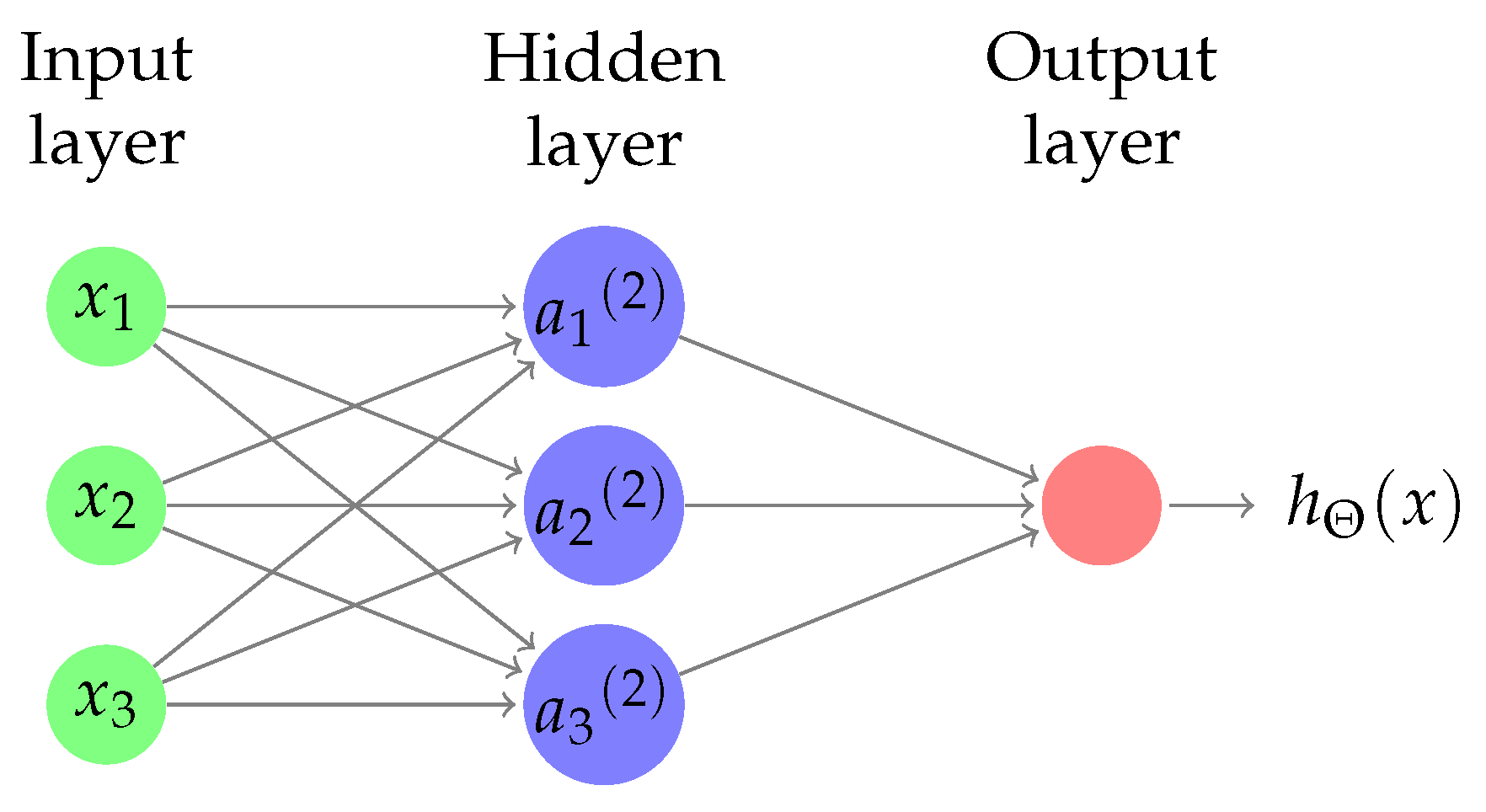
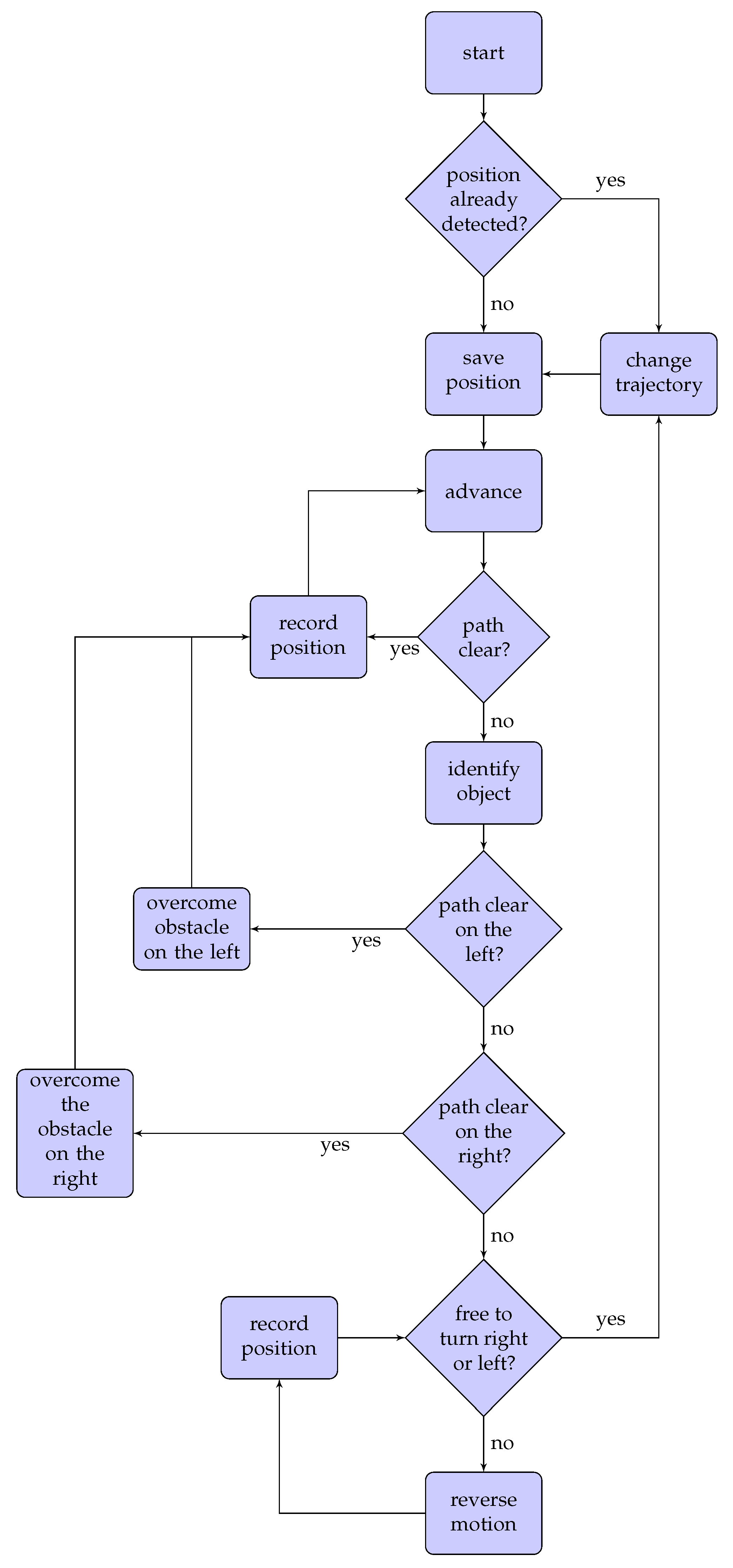
2. Neural Network Algorithm

The goals of neural network research are to better understand the human brain and develop algorithms that can deal with abstract problems. Borrowing from the description of the biological neuron, a node, in a neural network, is a computational unit that takes a series of inputs, thanks to incoming connections, performs calculations in the “cellular” body and sends outputs to other nodes through an outgoing connection.
The neural network’s architecture reported in Figure 1 is the most commonly-used structure. Generally, a network is made of three layers: input layers, hidden layers and output layers. In the scheme, in green are reported the input nodes, and the input values are indicated with x 1 , x 2 and x 3 . In blue, the hidden layer is reported with a 1 , a 2 and a 3 , representing the cellular bodies. Finally, the output layer is in red, with the final hypothesis output. Input layer nodes are also called passive nodes because they do not change the input data, but they receive and duplicate data for their multiple outputs, while the hidden layers and the output layers are defined both as active nodes.
h θ ( x ) = g Θ 0 a 0 + Θ 1 a 1 + Θ 2 a 2 + Θ 3 a 3
In (1), the hypothesis function is reported, which returns the output y starting from x input parametrized by Θ 0 , also called the weight matrix. The cost function for an artificial neural network, reported in (2), is nothing more than a more generalized form of the logistic regression cost function, in which rather than having only one output unit, there are three.
J ( Θ ) = 1 m i = 1 m i = 1 K y k ( i ) l o g h Θ x i k + 1 y k i l o g 1 h Θ x i k + λ 2 m l = 1 L 1 i = 1 s l j = 1 s l + 1 Θ i j l 2
Machine learning typically works with three large randomly sampled datasets =. The largest one should be the training set. Such data teach the net how to weigh different features, assigning coefficients in order to minimize training errors. Such coefficients, known as metadata, are contained in vectors. The network that we used for the object detection problem is a two-layer feed-forward network, with the sigmoid transfer function both in the hidden layer and in the output layer. The number of neurons in the hidden layer is set to 500. The number of neurons in the output layer is set to three since it is the number of elements of the target vector.

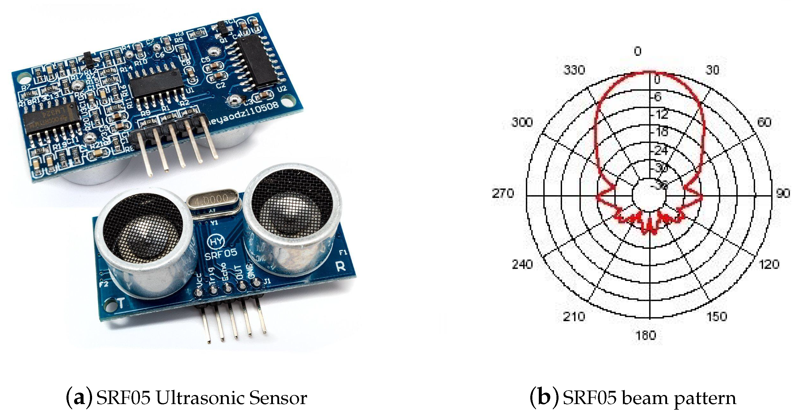
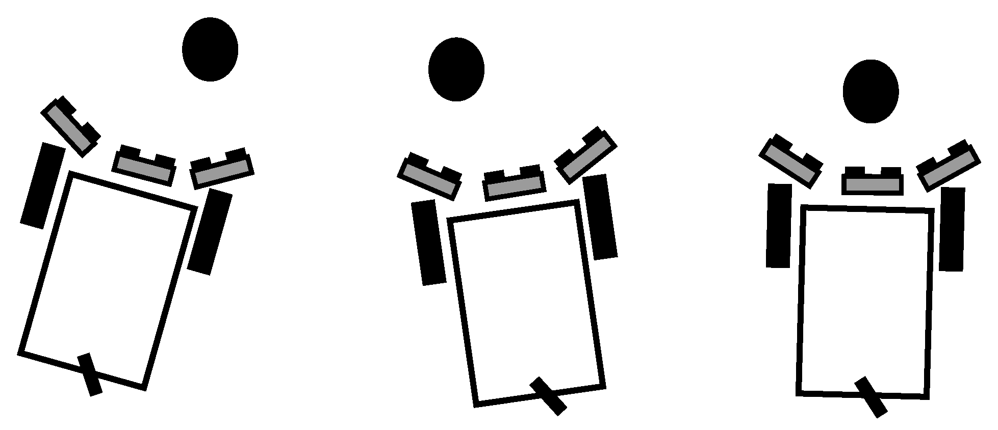
3. Preliminary Analysis

To test such a method for object recognition, we decided to conduct a preliminary study on a test-rig by using the SRF05 ultrasonic sensors. The test-rig used for this analysis is made of 60 cm-long Bosh aluminum profiles. On the structure, five ultrasonic sensor are installed as reported in Figure 2. For this application, we decided to use three objects, a cylinder with a regular shape, reported in Figure 2a, a cone and a parallelepiped with an irregular shape, reported in Figure 2b. For the acquisition campaign, we decided to carry out 3300 data acquisitions, moving, for each campaign, the position of the objects with respect to the five sensors.
The ultrasonic sensor used in our application is the SRF05 Ultra-sonic ranger, reported in Figure 3a. The low-cost ultrasonic sensor SRF05 is a sensor capable of evaluating distances from 1 cm up to 4 m. It was born as an evolution of the “SRF-04” and was designed to improve flexibility, the range of action and to further reduce costs compared to the previous model. It consists essentially of two sonar transducers installed on an electronic board, one that emits a sound signal and one that receives it. To perform the measurement, a short pulse of 10 µs must be supplied to the trigger input to start the sensor. The emitter will send a burst of eight ultrasound cycles at 40 kHz and increase the echo line. The SRF05 waits for the echo, and as soon as the signal is detected, the echo line is lowered again. The echo line is therefore an impulse whose width is proportional to the distance of the object. The measurement can be calculated from the pulse time.
In Figure 3b is reported the beam pattern diagram. By listening for the returning wave-fronts, the sonar detects the echo signal. Such a signal has an attack/decay envelope. Such an envelope means that it builds up to a peak value then fades away. Depending on which wave-front is the first to be detected, depending on which could be the first, second or even third, the result may differ. Another problem that can affect accuracy is the phasing effect when the point of the source of the echo is coming from another source, like in cases of long surfaces. In this case, it is important to make sure to measure only by using the first wave-fronts. In the presence of several ultrasonic sensors, as in our case, it is also necessary to defer the moment of activation of each sensor, thus avoiding false readings from waves sent by other sensors. In particular, the manufacturer suggests to fire them sequentially 65-ms apart.
In Figure 4 is reported the neural network scheme for the experimental activities. As reported, the input data are provided by the five sensors, while the outputs are the three chosen objects.
Therefore, for the cylinder, we will have the vector h θ ( x ) [ 1 , 0 , 0 , 0 ] T , for the cone, the vector h θ ( x ) [ 0 , 1 , 0 , 0 ] T , and finally, for the parallelepiped, the vector h θ ( x ) [ 0 , 0 , 1 , 0 ] T . Therefore, given the training set { ( x ( 1 ) , y ( 1 ) ) , , ( x ( n ) , y ( n ) ) } , we used the MATLAB neural network tool to design, train and display the neural network to be loaded later on the on-board controller.
In Table 1 is reported the usage of the data collected for the validation and testing of the network. The training samples are presented to the network during training, and the network is adjusted according to its error, while the validation data, instead, are used to measure network generalization and to halt training when the generalization stops improving. Furthermore, the testing samples do not have any effect on the training sample and so provide an independent measure of network performance.
In Figure 5 are reported the confusion matrices of the trained neural network for the preliminary activity. The rows of such matrices correspond to the predicted classes, and the columns report the true classes. The diagonal cells show how many classes of observation and what percentage are correctly estimated by the trained network. By analyzing the training confusion matrix, reported in Figure 5a, we can observe that the cylinder, having a regular geometry, is correctly recognized 919 times corresponding to 100% of the time. Instead, in the case of irregular geometries such as the cone and the parallelepiped, the network is not always able to correctly identify which object it is. In the case of the cone, only 501 cases correctly identify the object as a cone, equal to 59.2%, while in 66.8% of cases, the parallelepiped is correctly identified. In total, we can state that 77.2% of the time, the network correctly identifies the geometry. In Figure 5b, the test confusion matrix is reported, which in a predictable way, confirms the previously-mentioned results. The relevant error, present in the identification of non-regular geometry objects, is due, in our opinion, to the interference of the signals of the various sensors.

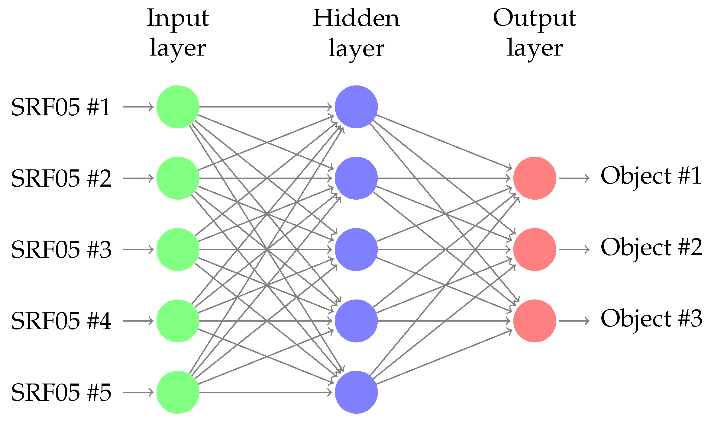
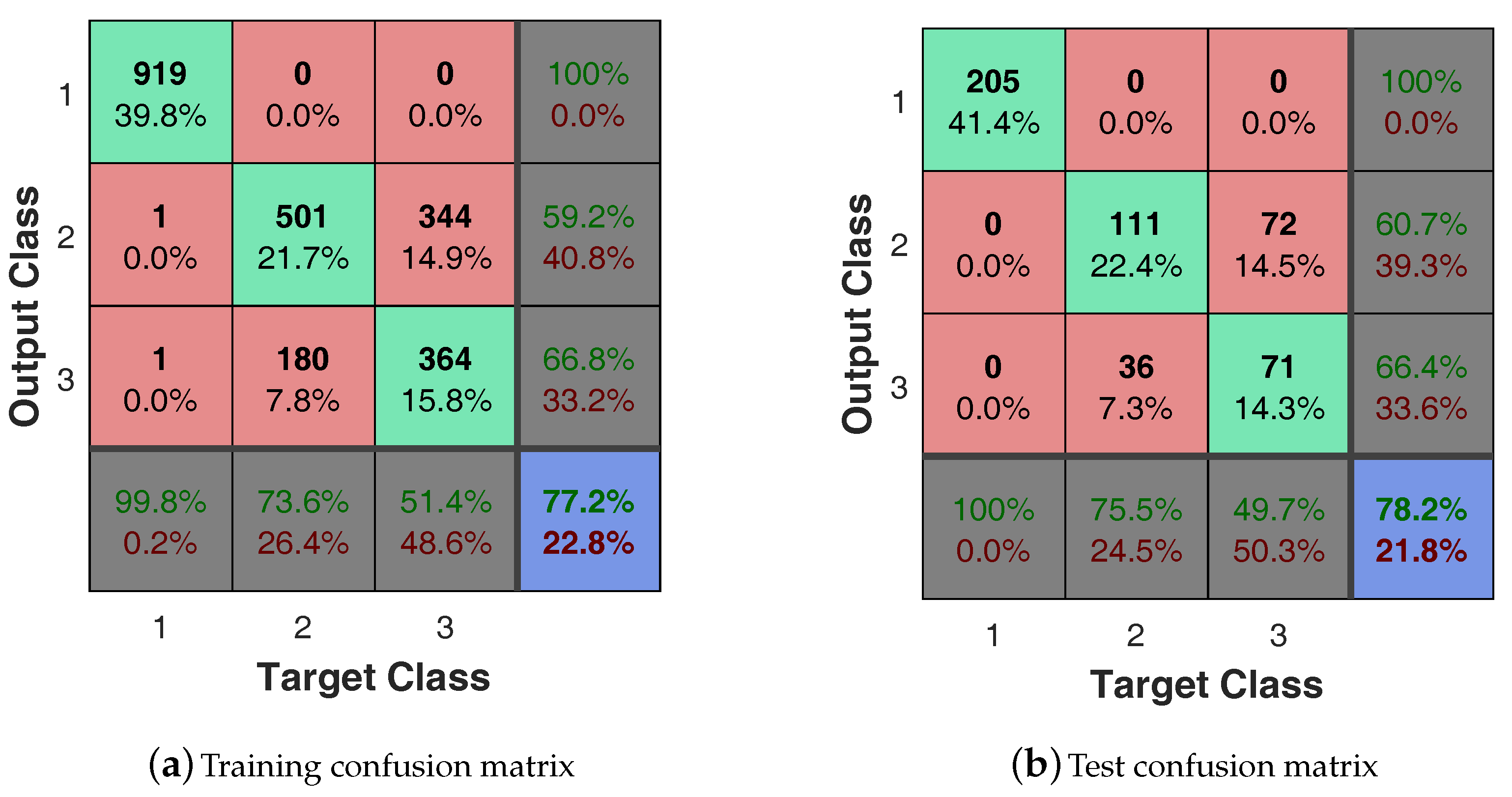
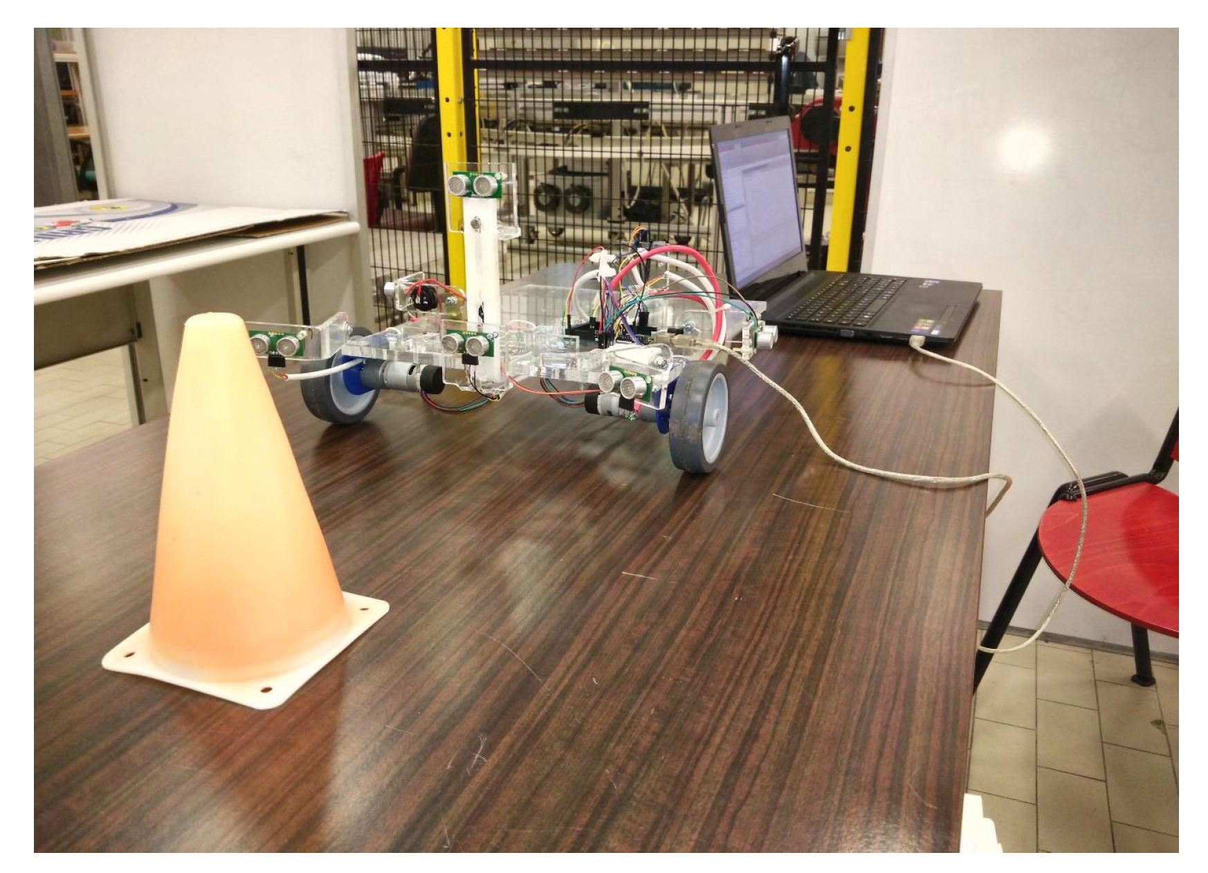
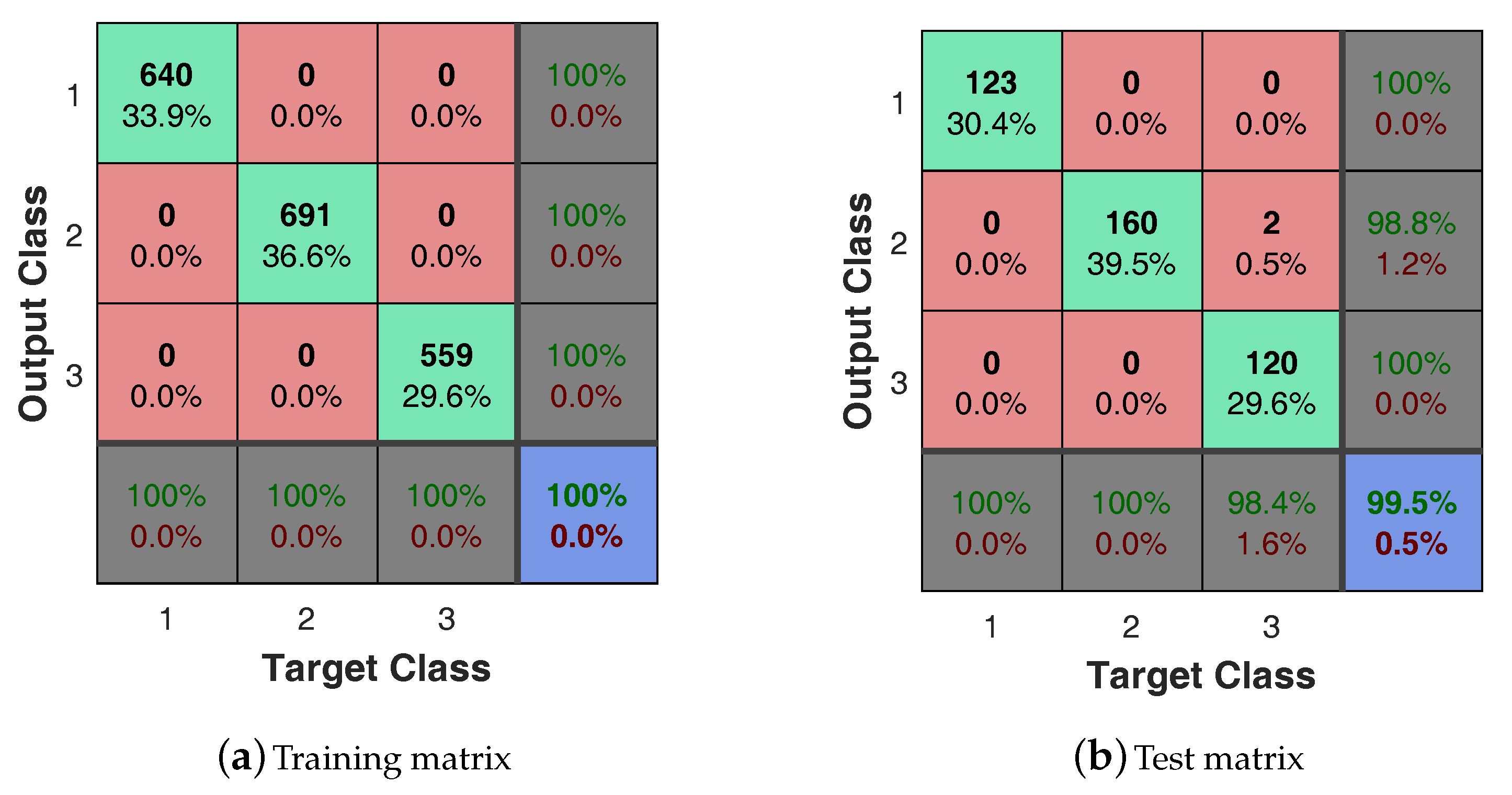
4. Experimental Activity

For the experimental activity, we used a small unmanned vehicle, built in our Laboratory of Applied Mechanics. The autonomous robot is a small three-wheeled system with two fixed-axis wheels driven by two EMG30 DC electric gear-motors with digital incremental encoders. The chassis of the vehicle is made of methyl-methacrylate. The onboard controller for this activity is an Arduino-Galileo, an Intel Quark SoC X1000 Application Processor board-based controller. Sensors, actuators and micro-controller are powered by a 12-Volt battery. The basic transducers’ configuration of the vehicle is made of ultrasonic sensors for detecting the presence of obstacles along the trajectory and a triple-axis gyroscope, a triple-axis magnetometer and a triple-axis accelerometer for the inertial navigation. To allow the robot to recognize such objects from any angle, measurements were obtained by randomly shifting the position of the three objects with respect to the five ultrasonic sensors, as shown in Figure 6. The unmanned vehicle is reported in Figure 7. As previously done, it was necessary to carry out a campaign of acquisition by the sensors mounted on the rover, in order to train and then test the new neural network. The collected data used for this second application are reported in Table 2.
In Figure 7 is reported the acquiring phase carried out on the cone. For this phase, we created a sub-routine in MATLAB capable of firing the ultrasonic sensors by serial communication with the Arduino controller. For the 27 sessions, 100 measurements were taken, every time changing the relative position of the object with respect to the sensors.
In Figure 8 is reported the confusion matrices of the trained neural network for the unmanned ground vehicle. The rows of such a matrix correspond to the predicted class, and the columns report the true class, as reported before. By analyzing the training matrix, reported in Figure 8a, we find a perfect identification of the three geometries confirming the fears about the interference between sensors, as stated by the SRF05 manufacturer. Instead, analyzing the testing matrix shown in Figure 8b, we can observe that only in two cases does the neural network incorrectly identify the parallelepiped in place of the cone, corresponding to 1.2% of the cases.
In Figure 9 is reported the list of operations carried out by the vehicle, during the patrol of the entire area, in search of objects to be recognized. Finally, Figure 10 shows the map created by the rover during its exploration phase of the perimeter. During navigation, it constantly uses the front and side ultrasonic sensors to detect the presence of objects and walls. The figure also shows the actual trajectory followed by the unmanned vehicle during the patrol.
Furthermore, the real position of the cylinder, cone and the parallelepiped is reported together with the enclosed area in which the robot can navigate. The robot is initially placed at the position (0, 0) inside the fence. At this stage, the autonomous vehicle does not know the position of objects distributed within the work area, the geometry of the work area nor its location within the area. However, the robot knows its footprint, information needed by the robot to perform maneuvering in the proximity of obstacles.
For navigation, the rover will try to advance until it finds an obstacle. In such a case, it will tend to overcome the obstacle by turning to its right if its path is free or it will turn to its left. Moving to the right or to the left will depend on the information collected by the side ultrasound sensors. In the case the robot cannot advance and there are obstructions on the sides, it will reverse its motion, as reported in Figure 9.

5. Conclusions

In this paper, the use of neural networks and ultrasonic sensors is tested for object identification. The idea is to use such a methodology on small autonomous agricultural machines by using retrofitting techniques. To do so, a small robot was used to test the potential of such a method. The UGV is a small three-wheeled system with two fixed-axis wheels driven by DC electric gear-motors with digital incremental encoders used for testing identification techniques and designing optimal control laws by the Applied Mechanics research team at the University of Salerno. Data collected by the five SRF05 sensors have been used to train the neural network so that it can recognize a cylinder, a cone and a parallelepiped. Once the network has been trained, the algorithm is tested by the autonomous navigating vehicle in an enclosure where the three objects to be recognized were present. During navigation, the vehicle correctly reports the type of object encountered and its position inside the enclosure. The result of this work will be also used for testing localization techniques based on the fusion of multiple sensors [69] for a tracked machine for agricultural applications.

Author Contributions

The work was mainly developed by the first and second authors (Marco Claudio De Simone and Zandra Betzabe Rivera). The critical review performed by the third author (Domenico Guida) is greatly appreciated.

Funding

This research received no external funding.

Conflicts of Interest

The authors declare no conflict of interest.

References

  1. Zhuge, C.; Cai, Y.; Tang, Z. A novel dynamic obstacle avoidance algorithm based on Collision time histogram. Chin. J. Electron. 2017, 26, 522–529. [Google Scholar] [CrossRef]
  2. Khan, M.; Hassan, S.; Ahmed, S.I.; Iqbal, J. Stereovision-based real-time obstacle detection scheme for Unmanned Ground Vehicle with steering wheel drive mechanism. In Proceedings of the 2017 International Conference on Communication, Computing and Digital Systems, C-CODE 2017, Islamabad, Pakistan, 8–9 March 2017; pp. 380–385. [Google Scholar]
  3. Ji, J.; Khajepour, A.; Melek, W.W.; Huang, Y. Path planning and tracking for vehicle collision avoidance based on model predictive control with multiconstraints. IEEE Trans. Veh. Technol. 2017, 66, 952–964. [Google Scholar] [CrossRef]
  4. Wang, Y.; Goila, A.; Shetty, R.; Heydari, M.; Desai, A.; Yang, H. Obstacle Avoidance Strategy and Implementation for Unmanned Ground Vehicle Using LIDAR. SAE Int. J. Commer. Veh. 2017, 10, 50–55. [Google Scholar] [CrossRef]
  5. Lee, S.; Cho, S.; Sim, S.; Kwak, K.; Park, Y.W.; Cho, K. A dynamic zone estimation method using cumulative voxels for autonomous driving. Int. J. Adv. Robot. Syst. 2017, 14. [Google Scholar] [CrossRef]
  6. Al-Mayyahi, A.; Wang, W.; Hussein, A.A.; Birch, P. Motion control design for unmanned ground vehicle in dynamic environment using intelligent controller. Int. J. Intell. Comput. Cybern. 2017, 10, 530–548. [Google Scholar] [CrossRef]
  7. Al-Mayyahi, A.; Wang, W.; Birch, P. Adaptive neuro-fuzzy technique for autonomous ground vehicle navigation. Robotics 2014, 3, 349–370. [Google Scholar] [CrossRef]
  8. Zoller, C.; Dasic, P.; Dobra, R.; Pantovic, R.; Damnjanovic, Z. Sequential Algorithm and Fuzzy Logic to Optimum Control the Ore Gridding Aggregates. Tech. Technol. Educ. Manag. 2012, 7, 914–919. [Google Scholar]
  9. Dasic, P. Determination of Reliability of Ceramic Cutting Tools on the basis of Comparative Analysis of Different Functions Distribution. Int. J. Qual. Rel. Manag. 2001, 18, 431–443. [Google Scholar]
  10. Serifi, V.; Dasic, P.; Jecmenica, R.; Labovic, D. Functional and Information Modeling of Production using IDEF Methods. Stro. Vest. J. Mech. Eng. 2009, 55, 131–140. [Google Scholar]
  11. Rajashekaraiah, G.; Sevil, H.E.; Dogan, A. PTEM based moving obstacle detection and avoidance for an unmanned ground vehicle. In Proceedings of the ASME 2017 Dynamic Systems and Control Conference, Tysons, VA, USA, 11–13 October 2017. [Google Scholar]
  12. Zhang, M.; Jasiobedzki, P. Unobtrusive and assistive obstacle avoidance for tele-operation of ground vehicles. In Proceedings of the SPIE—The International Society for Optical Engineering, Trieste, Italy, 31 May 2017; p. 10195. [Google Scholar]
  13. Giesbrecht, J.; Ng, H.-K.; Zhang, M.; Tang, J.; Bondy, M.; Jasiobedzki, P. Safeguarding autonomy through intelligent shared control. In Proceedings of the SPIE—The International Society for Optical Engineering, San Francisco, CA, USA, 28 January–2 February 2017; p. 10195. [Google Scholar]
  14. Mohammadi, S.S.; Khaloozadeh, H. Optimal motion planning of unmanned ground vehicle using SDRE controller in the presence of obstacles. In Proceedings of the 4th International Conference on Control, Instrumentation, and Automation, ICCIA, Qazvin, Iran, 27–28 January 2016; pp. 167–171. [Google Scholar]
  15. Tee Kit Tsun, M.; Lau, B.T.; Siswoyo Jo, H. An Improved Indoor Robot Human-Following Navigation Model Using Depth Camera, Active IR Marker and Proximity Sensors Fusion. Robotics 2018, 7, 4. [Google Scholar] [CrossRef]
  16. De Simone, M.C.; Guida, D. Identification and Control of a Unmanned Ground Vehicle by Using Arduino. UPB Sci. Bull. Ser. D 2018, 80, 141–154. [Google Scholar]
  17. González, A.; Olazagoitia, J.L.; Vinolas, J. A Low-Cost Data Acquisition System for Automobile Dynamics Applications. Sensors 2018, 18, 366. [Google Scholar] [CrossRef] [PubMed]
  18. De Simone, M.C.; Guida, D. On the Development of a Low Cost Device for Retrofitting Tracked Vehicles for Autonomous Navigation. In Proceedings of the XXIII Conference of the Italian Association of Theoretical and Applied Mechanics (AIMETA 2017), Salerno, Italy, 4–7 September 2017. [Google Scholar]
  19. Negrete, J.C.; Kriuskova, E.R.; Canteñs, G.D.J.L.; Avila, C.I.Z.; Hernandez, G.L. Arduino Board in the Automation of Agriculture in Mexico, a Review. Int. J. 2018, 8, 52–68. [Google Scholar] [CrossRef]
  20. Guida, D.; Nilvetti, F.; Pappalardo, C.M. Mass, Stiffness and Damping Identification of a Two-story Building Model. In Proceedings of the 3rd ECCOMAS Thematic Conference on Computational Methods in Structural Dynamics and Earthquake Engineering (COMPDYN 2011), Corfu, Greece, 25–28 May 2011; pp. 25–28. [Google Scholar]
  21. Pappalardo, C.M.; Guida, D. Experimental Identification and Control of a Frame Structure using an Actively Controlled Inertial-based Vibration Absorber. In Proceedings of the International Conference on Control, Artificial Intelligence, Robotics and Optimization (ICCAIRO 2017), Prague, Czech Republic, 20–22 May 2017; pp. 99–104. [Google Scholar]
  22. Guida, D.; Nilvetti, F.; Pappalardo, C.M. On Parameter Identification of Linear Mechanical Systems. In Proceedings of the 3rd International Conference on Applied Mathematics, Simulation, Modelling, Circuits, Systems and Signals, (WSEAS), Vouliagmeni Beach, Athens, Greece, 29–31 December 2009; pp. 55–60. [Google Scholar]
  23. Guida, D.; Nilvetti, F.; Pappalardo, C.M. Parameter Identification of a Two Degrees of Freedom Mechanical System. Int. J. Mech. 2009, 3, 23–30. [Google Scholar]
  24. Guida, D.; Pappalardo, C.M. Sommerfeld and Mass Parameter Identification of Lubricated Journal Bearing. WSEAS Trans. Appl. Theor. Mech. 2009, 4, 205–214. [Google Scholar]
  25. De Simone, M.C.; Russo, S.; Rivera, Z.B.; Guida, D. Multibody Model of a UAV in Presence of Wind Fields. In Proceedings of the 2017 International Conference on Control, Artificial Intelligence, Robotics & Optimization (ICCAIRO), Prague, Czech Republic, 20–22 May 2017; pp. 83–88. [Google Scholar]
  26. De Simone, M.C.; Guida, D. Control Design for an Under-Actuated UAV Model. FME Trans. 2018. accepted for publication. [Google Scholar]
  27. Concilio, A.; De Simone, M.C.; Rivera, Z.B.; Guida, D. A New Semi-Active Suspension System for Racing Vehicles. FME Trans. 2017, 45, 565–571. [Google Scholar] [CrossRef]
  28. Villecco, F.; Pellegrino, A. Entropic measure of epistemic uncertainties in multibody system models by axiomatic design. Entropy 2017, 19, 291. [Google Scholar] [CrossRef]
  29. Pellegrino, A.; Villecco, F. Design Optimization of a Natural Gas Substation with Intensification of the Energy Cycle. Math. Probl. Eng. 2010, 2010, 294102. [Google Scholar] [CrossRef]
  30. Formato, A.; Ianniello, D.; Villecco, F.; Lenza, T.L.L.; Guida, D. Design optimization of the plough working surface by computerized mathematical model. Emir. J. Food Agric. 2017, 29, 36–44. [Google Scholar] [CrossRef]
  31. Villecco, F.; Pellegrino, A. Evaluation of Uncertainties in the Design Process of Complex Mechanical Systems. Entropy 2017, 19, 475. [Google Scholar] [CrossRef]
  32. Quatrano, A.; De Simone, M.C.; Rivera, Z.B.; Guida, D. Development and Implementation of a Control System for a retrofitted CNC Machine by using Arduino. FME Trans. 2017, 45, 578–584. [Google Scholar] [CrossRef]
  33. Pappalardo, C.M.; Patel, M.D.; Tinsley, B.; Shabana, A.A. Contact Force Control in Multibody Pantograph/Catenary Systems. Proc. Inst. Mech. Eng. Part K J. Multibody Dyn. 2016, 230, 307–328. [Google Scholar] [CrossRef]
  34. Guida, D.; Nilvetti, F.; Pappalardo, C.M. Optimal Control Design by Adjoint-Based Optimization for Active Mass Damper with Dry Friction. In Proceedings of the 4th International Conference on Computational Methods in Structural Dynamics and Earthquake Engineering COMPDYN 2013, Kos Island, Greece, 12–14 June 2013; pp. 1–19. [Google Scholar]
  35. Pappalardo, C.M.; Patel, M.D.; Tinsley, B.; Shabana, A.A. Pantograph/Catenary Contact Force Control. In Proceedings of the ASME 2015 International Design Engineering Technical Conferences and Computers and Information in Engineering Conference IDETC/CIE 2015, Boston, MA, USA, 2–5 August 2015. [Google Scholar]
  36. Guida, D.; Pappalardo, C.M. Control Design of an Active Suspension System for a Quarter-Car Model with Hysteresis. J. Vib. Eng. Technol. 2015, 3, 277–299. [Google Scholar]
  37. Haus, T.; Orsag, M.; Bogdan, S. Mathematical Modelling and Control of an Unmanned Aerial Vehicle with Moving Mass Control Concept. J. Intell. Robot. Syst. Theory Appl. 2017, 88, 219–246. [Google Scholar] [CrossRef]
  38. Guida, D.; Pappalardo, C.M. A New Control Algorithm for Active Suspension Systems Featuring Hysteresis. FME Trans. 2013, 41, 285–290. [Google Scholar]
  39. Pappalardo, C.M.; Guida, D. Adjoint-based Optimization Procedure for Active Vibration Control of Nonlinear Mechanical Systems. ASME J. Dyn. Syst. Meas. Control 2017, 139, 1–11. [Google Scholar] [CrossRef]
  40. Sharifzadeh, M.; Farnam, A.; Senatore, A.; Timpone, F.; Akbari, A. Delay-dependent criteria for robust dynamic stability control of articulated vehicles. Mech. Mach. Sci. 2018, 49, 424–432. [Google Scholar] [CrossRef]
  41. Dasic, P.; Dasic, J.; Crvenkovic, B. Applications of Access Control as a Service for Software Security. Int. J. Ind. Eng. Manag. 2016, 7, 111–116. [Google Scholar]
  42. Dasic, P.; Dasic, J.; Crvenkovic, B. Service Models for Cloud Computing: Search as a Service (SaaS). Int. J. Eng. Tech. 2016, 8, 2366–2373. [Google Scholar] [CrossRef]
  43. Pappalardo, C.M.; Yu, Z.; Zhang, X.; Shabana, A.A. Rational ANCF Thin Plate Finite Element. ASME J. Comput. Nonlinear Dyn. 2016, 11, 1–15. [Google Scholar] [CrossRef]
  44. Pappalardo, C.M.; Wallin, M.; Shabana, A.A. A New ANCF/CRBF Fully Parametrized Plate Finite Element. ASME J. Comput. Nonlinear Dyn. 2017, 12, 1–13. [Google Scholar]
  45. Pappalardo, C.M.; Wang, T.; Shabana, A.A. Development of ANCF Tetrahedral Finite Elements for the Nonlinear Dynamics of Flexible Structures. Nonlinear Dyn. 2017, 89, 2905–2932. [Google Scholar] [CrossRef]
  46. Pappalardo, C.M.; Wang, T.; Shabana, A.A. On the Formulation of the Planar ANCF Triangular Finite Elements. Nonlinear Dyn. 2017, 89, 1019–1045. [Google Scholar] [CrossRef]
  47. Guida, D.; Nilvetti, F.; Pappalardo, C.M. Adjoint-based Optimal Control Design for a Cart Pendulum System with Dry Friction. In Proceedings of the Programme and ECCOMAS Thematic Conference on Multibody Dynamics, Zagreb, Croatia, 1–4 July 2013; pp. 269–285. [Google Scholar]
  48. Lekic, M.; Cvejic, S.; Dasic, P. Iteration Method for Solving Differential Equations of Second Order Oscillations. Tech. Technol. Educ. Manag. 2012, 7, 1751–1759. [Google Scholar]
  49. Sharifzadeh, M.; Timpone, F.; Farnam, A.; Senatore, A.; Akbari, A. Tyre-Road Adherence Conditions Estimation for Intelligent Vehicle Safety Applications. In Advances in Italian Mechanism Science; Springer: Berlin/Heidelberg, Germany, 2017; pp. 389–398. [Google Scholar]
  50. Guida, D.; Nilvetti, F.; Pappalardo, C.M. Experimental Investigation on a New Hybrid Mass Damper. In Proceedings of the 8th International Conference on Structural Dynamics (EURODYN 2011), Leuven, Belgium, 4–6 July 2011; pp. 1644–1649. [Google Scholar]
  51. Ruggiero, A.; Affatato, S.; Merola, M.; De Simone, M.C. FEM analysis of metal on UHMWPE total hip prosthesis during normal walking cycle. In Proceedings of the XXIII Conference of the Italian Association of Theoretical and Applied Mechanics (AIMETA 2017), Salerno, Italy, 4–7 September 2017. [Google Scholar]
  52. Cuccurullo, G.; Giordano, L.; Metallo, A. Analytical solutions for tomato peeling with combined heat flux and convective boundary conditions. J. Phys. Conf. Ser. 2017, 923, 1–9. [Google Scholar] [CrossRef]
  53. Gao, Y.; Villecco, F.; Li, M.; Song, W. Multi-Scale Permutation Entropy Based on Improved LMD and HMM for Rolling Bearing Diagnosis. Entropy 2017, 19, 176. [Google Scholar] [CrossRef]
  54. Milosavljevic, B.; Pesic, R.; Dasic, P. Binary Logistic Regression Modeling of Idle CO Emissions in order to Estimate Predictors Influences in Old Vehicle Park. Math. Probl. Eng. 2015, 2015, 463158. [Google Scholar] [CrossRef]
  55. Guida, D.; Nilvetti, F.; Pappalardo, C.M. Dry Friction Influence on Cart Pendulum Dynamics. Int. J. Mech. 2009, 3, 31–38. [Google Scholar]
  56. Ruggiero, A.; De Simone, M.C.; Russo, D.; Guida, D. Sound pressure measurement of orchestral instruments in the concert hall of a public school. Int. J. Circuits Syst. Signal Process. 2016, 10, 75–812. [Google Scholar]
  57. Dasic, P. Examples of Analysis of Different Functions of Cutting Tool Failure Distribution. Trib. Ind. 1999, 21, 59–67. [Google Scholar]
  58. Dasic, P.; Natsis, A.; Petropoulos, G. Models of Reliability for Cutting Tools: Examples in Manufacturing and Agricultural Engineering. Stro. Vest. J. Mech. Eng. 2008, 54, 122–130. [Google Scholar]
  59. De Simone, M.C.; Rivera, Z.B.; Guida, D. Finite Element Analysis on Squeal-Noise in Railway Applications. FME Trans. 2018, 46, 93–100. [Google Scholar] [CrossRef]
  60. Guida, D.; Nilvetti, F.; Pappalardo, C.M. Instability Induced by Dry Friction. Int. J. Mech. 2009, 3, 44–51. [Google Scholar]
  61. De Simone, M.C.; Guida, D. Dry Friction Influence on Structure Dynamics. In Proceedings of the 5th ECCOMAS Thematic Conference on Computational Methods in Structural Dynamics and Earthquake Engineering (COMPDYN 2015), Crete Island, Greece, 25–27 May 2015; pp. 4483–4491. [Google Scholar]
  62. Guida, D.; Nilvetti, F.; Pappalardo, C.M. Dry Friction Influence on Inverted Pendulum Control. In Proceedings of the 3rd International Conference on Applied Mathematics, Simulation, Modelling (ASM’09), Vouliagmeni Beach, Athens, Greece, 29–31 December 2009; pp. 49–54. [Google Scholar]
  63. De Simone, M.C.; Guida, D. Modal Coupling in Presence of Dry Friction. Machines 2018, 6, 8. [Google Scholar] [CrossRef]
  64. Pappalardo, C.M.; Guida, D. Control of Nonlinear Vibrations using the Adjoint Method. Meccanica 2017, 52, 2503–2526. [Google Scholar] [CrossRef]
  65. Guida, D.; Nilvetti, F.; Pappalardo, C.M. Friction Induced Vibrations of a Two Degrees of Freedom System. In Proceedings of the 10th WSEAS International Conference on Robotics, Control and Manufacturing Technology (ROCOM ’10), Hangzhou, China, 11–13 April 2010; pp. 133–136. [Google Scholar]
  66. Guida, D.; Pappalardo, C.M. Forward and Inverse Dynamics of Nonholonomic Mechanical Systems. Meccanica 2014, 49, 1547–1559. [Google Scholar] [CrossRef]
  67. Pappalardo, C.M. A Natural Absolute Coordinate Formulation for the Kinematic and Dynamic Analysis of Rigid Multibody Systems. Nonlinear Dyn. 2015, 81, 1841–1869. [Google Scholar] [CrossRef]
  68. Guida, D.; Pappalardo, C.M. On the use of Two-dimensional Euler Parameters for the Dynamic Simulation of Planar Rigid Multibody Systems. Arch. Appl. Mech. 2017, 1–19. [Google Scholar] [CrossRef]
  69. Li, B.; Liu, H.; Zhang, J.; Zhao, X.; Zhao, B. Small UAV autonomous localization based on multiple sensors fusion. In Proceedings of the 2017 IEEE 2nd Advanced Information Technology, Electronic and Automation Control Conference, IAEAC, Chongqing, China, 25–26 March 2017; pp. 296–303. [Google Scholar] [CrossRef]
Figure 1. Neural network scheme with the input layer, hidden layer and output layer.
Machines 06 00018 g001
Figure 2. Experimental test-rig used for the preliminary analysis made of Bosh aluminum profiles on which the SRF05 sensors were installed.
Machines 06 00018 g002
Figure 3. SRF05 ultrasonic sensor and conical beam pattern of the sensor.
Machines 06 00018 g003
Figure 4. Structure of the neural network used for the experimental application.
Machines 06 00018 g004
Figure 5. Confusion matrices for the training and test activity for the preliminary analysis.
Machines 06 00018 g005
Figure 6. Scheme of the network training activity by moving the position of the object relative to the rover.
Machines 06 00018 g006
Figure 7. Data acquisition process for the cone geometry.
Machines 06 00018 g007
Figure 8. Confusion matrices for the training and test activity for the experimental application.
Machines 06 00018 g008
Figure 9. Program flowchart showing the overview of the robot navigation operations.
Machines 06 00018 g009
Figure 10. Map of the enclosure with the arrangement of objects within it.
Machines 06 00018 g010
Table 1. Dataset distribution for the preliminary analysis.
DatasetSize
Total data3300 samples
Training set2310 samples
Validation set495 samples
Testing set495 samples
Table 2. Acquired dataset distribution for neural network training.
DatasetSize
Total data2700 samples
Training set1890 samples
Validation set405 samples
Testing set405 samples

