Article

Concentrated Windings in Compact Permanent Magnet Synchronous Generators: Managing Efficiency

1
Rectorat de Lille, Clg DESCARTES, 2 rue Lavoisier, 59370 Mons-En-Baroeul, France
2
AREVA NP, 27 rue de l’Industrie BP 20189, 59573 Jeumont Cedex, France
*
Author to whom correspondence should be addressed.
Machines 2016, 4(1), 2; https://doi.org/10.3390/machines4010002
Submission received: 7 August 2015 / Revised: 2 October 2015 / Accepted: 2 November 2015 / Published: 5 January 2016
(This article belongs to the Special Issue Feature Papers)

Abstract

:
In electric power generation, customers want generators with high efficiency. Nowadays, modern turbo-generators have efficiencies greater than 98%. Although this amount should not be obtained for all kind of machines, efficiency will remain one of the main parameters for customer choice. Efficiency is also linked to the life of the machine: the higher the efficiency is, the longer the machine’s lifetime. During the past decade, new forms of energy production have appeared and generators have been developed to fit well into this market. For example, wind generators evolved towards permanent magnet generators having high polarity and running at low speed. Nevertheless, their structure is not fixed. An industrial company has built a prototype of such a generator which uses fractional-slot concentrated-windings (FSCW). This kind of winding is not the structure used by default in such electrical machines. Another field of interest is in autonomous generators which can be used on boats. Even if everyone has in mind large merchant ships, we must not forget smaller ships, such as fishing boats and short-range cruise ships, which spend the most of their time near the coast. This kind of ship does nothave large areas for installing the electric generation or the electric propulsion. It is the reason why, in this article, we focus on the efficiency of machines using fractional-slot concentrated-windings. In many publications which compare performances between distributed and concentrated windings, the result is almost the same. The efficiency of FSCW is not as high as the efficiency associated to the machines which are using distributed windings. Design methods have to be redrawn to integrate, as soon as possible, the loss mitigation in order to provide the best efficiency in power conversion. The following discussion, step by step, introduces the loss mitigation in every part of a machine using FSCW. To close the discussion, a design is produced and it appears that efficiency can be enhanced with suitable design methods.

Graphical Abstract

1. Introduction

Permanent magnet generators are suitable generators where standalone operations are required. Moreover, their high efficiencies are generally considered as the main advantage. A large number of manufactured machines is using a conventional winding structure: distributed windings. This structure fits well with high-power machines, such as multi-megawatt generators. Unfortunately, the distributed winding has its drawbacks, especially in the length of the end windings, which are outside the active part. Fractional-slot concentrated-windings do not have this drawback. The small volume of their end windings allows a short axial length [1]. One manufacturer, Fuji Electric, has initiated studies and experiments on a high-power generator that uses FSCW [2]. Comparisons between concentrated and distributed windings, show a lack of efficiency in machines using concentrated windings [3,4,5]. This machines provide between 1% and 5% less in efficiency and lower power factor. Much effort will be required for making these machines as popular as machines using distributed windings. Looking at the increase in efficiency, it will be a global work if these machines have to take a place into the market of industrial motors or generators. Hence, solutions that can reply to this objective have to be discovered using a global view of machine design. It must be noted that efficiency depends on losses. The mitigation of losses is not a straightforward job. Some losses can be easily managed and others not. Recent studies show that the main losses are iron core losses and Joule losses, magnet losses are not forgotten but they are, in many cases, less important. The first part of this discussion provides general information about electric machines which are using FSCW. In doing so, drawbacks are highlighted and some configurations will be declared unusable. The second part is related to the development of power generation. The rated power of variable speed generators is increasing year by year and the design must be adapted in order to remain within an economically viable price. Thereafter, it will appear that multi-star structures or the multiphase structures can be a solution in efficiency enhancement when machines are controlled by electric power inverters. Such a structure decreases the harmonics of magnetic fields in air-gaps but could not suppress the magnetic coupling between the stars [6]. The iron losses mainly depend on the magnetic flux flow. The following section highlights this and points out particular behaviors which have to be integrated in the first stages of design. The machines which are built with FSCW are versatile. In one stator, more than one rotor can be inserted. For example, in a stator having 24 slots, a rotor having 20 poles or 28 poles can be inserted and they can run well. The next section shows why this versatility is not conducive to efficiency. The final sections are dedicated to the design of a machine that should provide efficiency as high as conventional generators used in power generation. The specifications focus on a variable speed generator whose operating frequency is up to 160 Hz. In doing so, all the sources of losses in such a machine have to be investigated. In the last section, it appears that it is possible to design a generator in which efficiency is as high as conventional machines. However, this study does not take into account the asynchronous machines that are now in interest of some laboratories [7,8]; it remains on permanent magnet machines which have a greater degree of realization and a well-identified market (wind generator, electric generation for ships, etc.).

2. Concentrated Winding: Overview

2.1. Advantages and Drawbacks

When a brief review is done about the machines that use the concentrated windings, it appears that their future roles would be the propulsion of electric vehicles (EV) [9]. Motors are integrated in the wheels and more free space is available for the accumulators. Many publications have described this winding structure as a structure that is able to provide a very low cogging torque which is suitable to ensure low mechanical stress [10]. The overall mass of copper is smaller and, one last advantage, that needs to be confirmed by numerous realizations, is the low manufacturing cost. With a stator which uses open slots, the coils can be formed outside and can be inserted into the stator without any difficulty and without any contact with the other coils.
Nowadays, this winding structure is not the structure used by default in the industries that manufacture high-power electrical machines. There is no know-how in this domain of application. No design rule can be provided to adapt a machine to the customer requirements. However, some low-voltage generators which are using concentrated windings have been manufactured and can be used as references [11]. Comparisons between distributed and concentrated windings show that such a structure increases the iron losses and provides a high level of magnetic field harmonics in the air-gap. This phenomenon is still not acceptable for the machines that use permanent magnets mounted on the surface of the rotor [5]. Recent studies, combined with measurements provide important information about losses in the magnets and invite designers to handle such losses in order to prevent any increase in the magnets’ temperature [12].

2.2. Design, State of the Art

Two main structures of windings exist, single layer and double layer [13,14]. Recent studies underline the drawbacks of the single layer windings. This structure increases the magnetic field harmonics in the air-gap and generates thermal stresses in the magnets. However, the single layer windings are generally presented as a winding structure that is fault-tolerant. In the single layer arrangement, all of the coils are separated by a tooth and a faulty coil could not damage the others. Many publications, such as the articles of professor Zi-Qiang Zhu located at Sheffield University, give solutions which are able to keep a low magnetic field harmonic in the air-gap and also have a high fault-tolerant capability. With an unequal tooth widths structure, the behavior of the single layer windings is very similar to the behavior of the double layer windings [15]. As a conclusion, even if the concentrated windings have been studied for more that forty years, there are not enough machines in operation which permits one to conclude about the way to design motors or generators in the high-power domain. It is sure that such machines are not actually the most important part of production. In recent articles, several configurations are investigated to answer to one specification [12]. Hence, such a structure can be employed when conventional structures are not usable, an increase in design cost can thereafter be justified.

3. Design and Requirement

The methods used in designing a generator or a motor depend on the specifications. The IEC or IEEE standards provide some specifications that have to be achieved by the designers. With this information, the designers have in mind a catalogue of machines that will satisfy a large number of customers. Any unusual specifications that come from specific uses are not in the scope. With standards, the main objective consists in lowering the manufacturing costs. On the other side, there is a small part of the market that will require some customized motors or generators. Nuclear power stations, ships, submarines, aircrafts etc, will not be equipped with standard electric machines. Even if the price of the machine is high, the customization is required to obtain the desired function. No customer wants a power-plant outage during the winter or a submarine which is noisier than a tug-boat.
The machines with special requirements must be designed with caution. Even if the sale price is high, it has to remain in accordance with the market price and the machine has to comply with the mandatory parameters of the customer. The customized machine is a market where all of the manufactures can show their know-how in design and engineering. In this study the main requirement is a high power density and a high efficiency without any specification about the number of phases. Hence, the number of phases can be different than three and the number of stars can be greater than one. The three-phase windings, which are the conventional windings, have been employed for a hundred years. The background knowledge is important. Unfortunately, the concentrated windings which will be selected for this study are not so popular, and there is no design rule associated to the choice of the number of phases or the choice of the number of stars. The increase in efficiency will be obtained by a decrease in losses. The machines which are using FSCW have the same sources of losses than machines using distributed windings. Looking at Figure 1, the particularity of each source will be discussed. With the use of FSCW, the core losses increase. The rotational flux that appears in the core must be taken into account not to underestimate the amount of losses. There are less Joule losses, because the volume of copper is lower. The losses in magnets have to be investigated with caution. The air-gap has a great amount of flux harmonics which induce high eddy currents in the magnets. Such a phenomenon is not so noticeable in machines using distributed windings. Even if these losses are not losses that strongly decrease the efficiency, such losses can heat and destroy the magnets. Mitigating these losses is a priority. The rotor losses could vanish and losses in magnets will be carefully investigated. Formally, the mechanical losses exist, they are very low, and the use of FSCW does not change anything about its calculation.
Figure 1. Main sources of losses in electrical machines. All of these sources have to be investigated in order to increase the efficiency of electrical generators which areusing FSCW.
Machines 04 00002 g001

4. Concentrated Winding and Design Rules

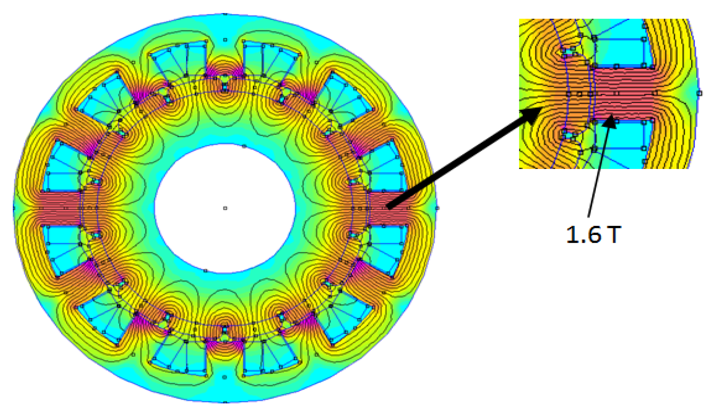
Although the methods used to determine the concentrated winding structure are well-known and fully documented all the designed structures are not machines that have been manufactured and tested. Staying in touch with manufacturers and their design engineers highlights some traps that should be avoided. This will initiate new design rules or can improve the current rules. They will be followed in the future. Looking at the number of poles and slots, it appears that numbers that are close to each other are preferable. For example, for a three-phase machine, having 14 poles and 12 slots, has better performances than a five-phase machine having 14 poles and 20 slots. This result is explained by the winding factor that is higher in the first case. First, making simulations, then observing the analysis of the magnetic flux flow, such an issue can be found and will also be demonstrated in the next paragraph. Two structures are examined, thereafter. The first one uses 14 poles and 12 slots and is presented in Figure 2. The second one also uses 14 poles but has 20 slots. It is shown in Figure 3. In the first figure, at a no-load case, the magnetic induction does not exceed 1.6 T, and in the second figure, the magnetic induction is above 1.8 T. A change in air-gap thickness does not modify anything in the flux distribution; the mechanical air-gap lacks enough influence on this one.
Figure 2. The magnetic flux distribution in a concentrated winding structure with 14 poles and 12 slots. At no-load case, the highest level of magnetic induction is in the teeth.
Machines 04 00002 g002
Figure 3. Magnetic flux distribution in a concentrated winding structure having 14 poles and 20 slots (Five phases). At no-load case, the highest level of induction is in the teeth and is higher than the level of induction found in the 12 slots structure (Figure 2). q, the number of slots per pole and phase is 0.28 and is not equal to 1/5 (1/Nph). The number of poles has to increase.
Machines 04 00002 g003
It is easy to understand that the high number of slots decreases the flux path section and implies a higher magnetic induction. This increases the iron losses in the teeth without any advantages. Skaar, Krøvel, and Nilssen have demonstrated that the best winding factor is obtained when q (number of slot per pole and phase) is close to 1/Nph [16]. This means q = 1/3 with a three-phase supply. This leads to the number of slots Ns close to the number of pole (q ≈ 1/3 ⇒ Ns ≈ Np ×3 × 1/3 ⇒ Ns ≈ Np). This can be summarized in a simple formulation, (Np +/− 2 = Ns), where Ns is the number of slots and Np is the number of poles [17,18]. Moreover, it is a good choice to prefer the number of slots be below the number of poles.
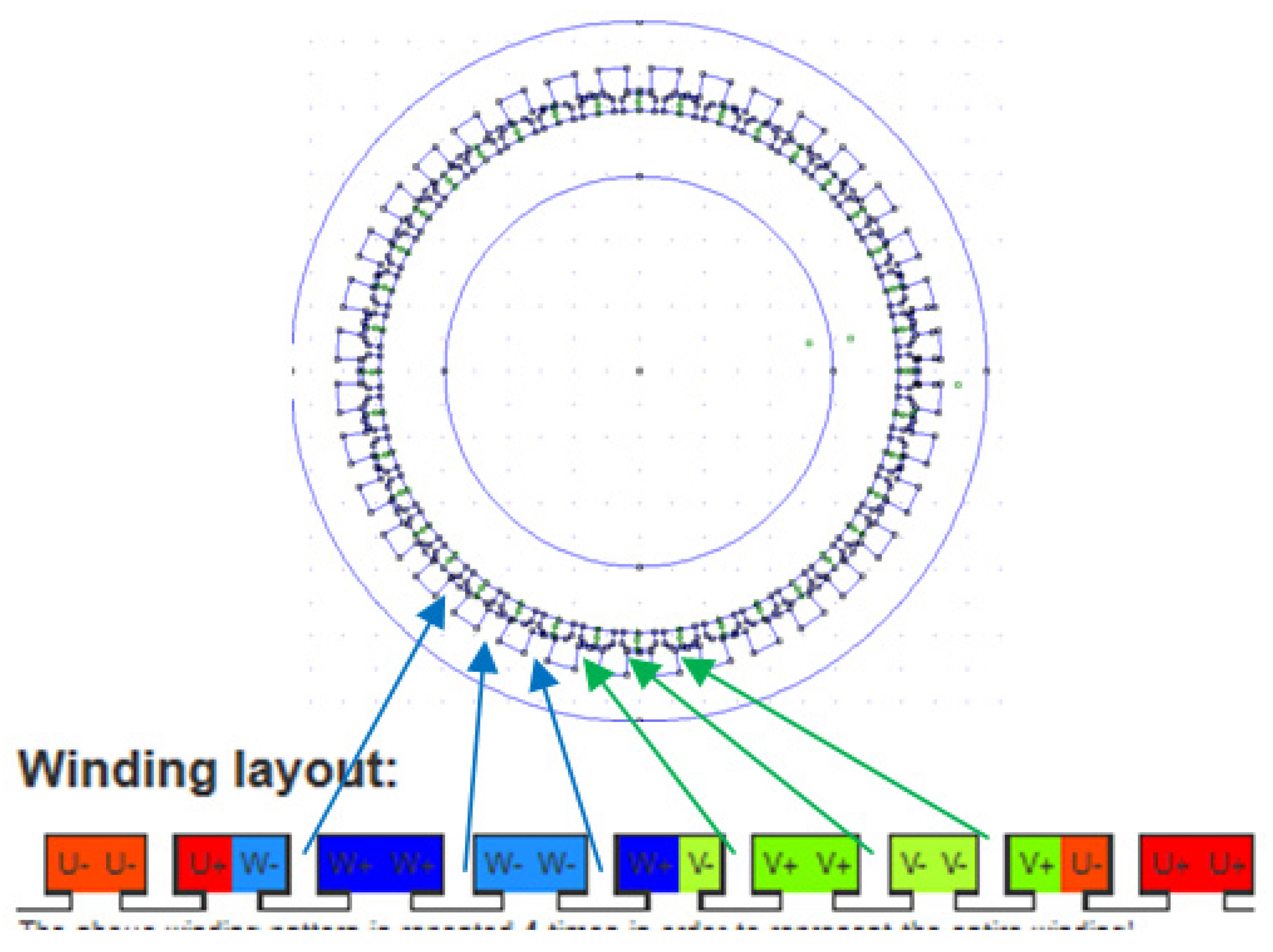
The selection of winding configurations that have a good winding factor is not enough to declare these structures “ready for use”. A drawback is presented thereafter: undesirable circulating currents can appear. With the following example the problem will be highlighted. A machine having 36 slots and 40 poles is examined. The number of slots is below the number of poles and the coils associated to the same phase are adjacent three-by-three (Figure 4). Anyone can verify this solution by using the website at Reference [19].
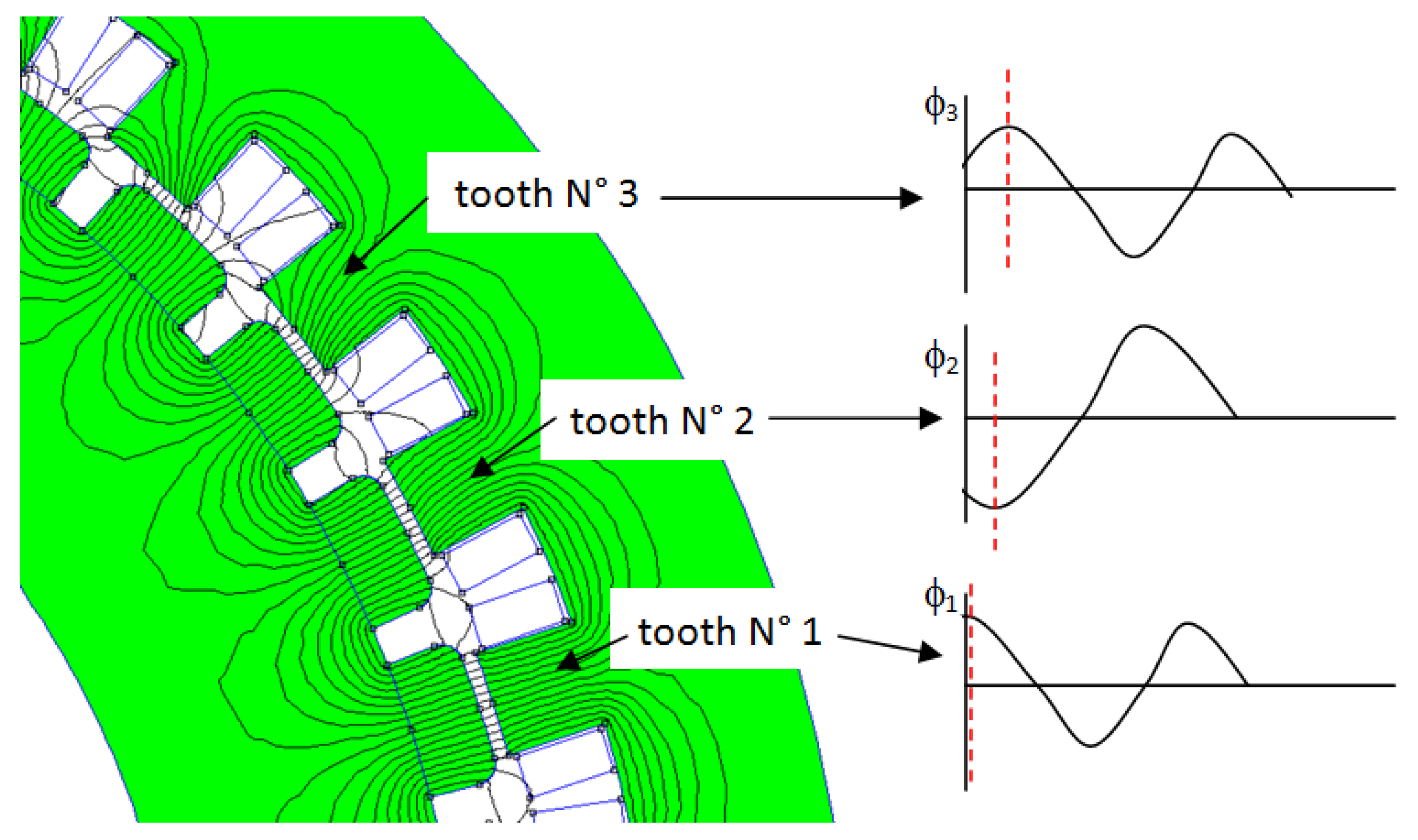
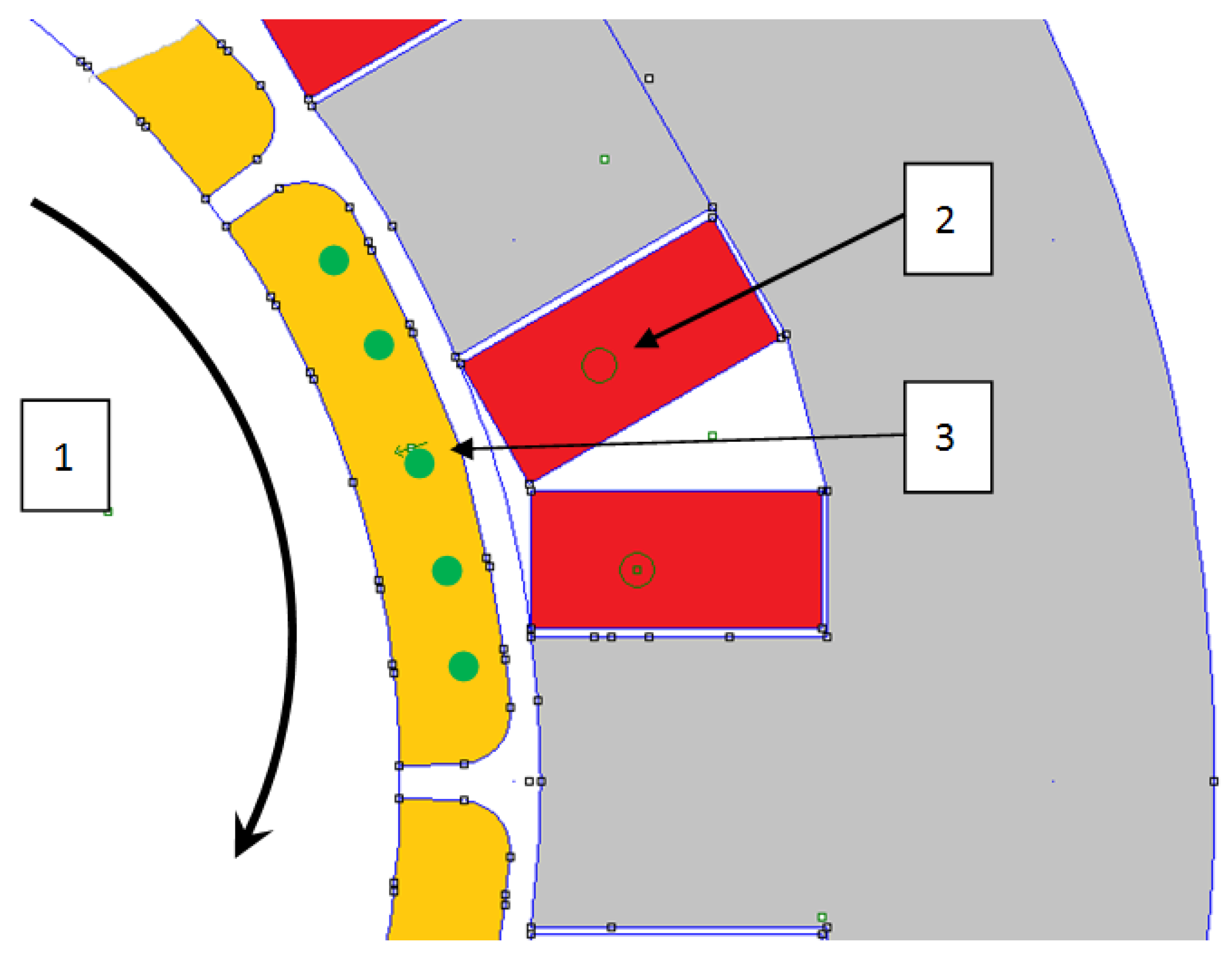
Looking at these three adjacent coils, it immediately appears that the magnetic flux induced by the permanent magnets does not have the same behavior in these three teeth. Although the magnitude of the magnetic flux in each tooth is similar, their shapes are not synchronized (Figure 5). Therefore, it means that induced voltages in these three coils attached to these three teeth are not synchronous. Designers who want to connect these coils in parallel will have a nasty surprise. Circulating currents will appear between these coils and these currents will not be present in the power line, leaving engineers the idea that all is working fine (Figure 6). Such circulating currents will increase the Joule losses and will also have a bad influence on the pulsating torque.
Figure 4. The structure of a generator having 40 poles and 36 slots is established in combining four times the basic winding layout. In the basic winding layout, the coils attached to the same phase are gathered three by three.
Machines 04 00002 g004
Figure 5. Partial view of the structure having 40 poles 36 slots; in a group of three adjacent teeth, the magnetic flux cannot be the same at each time.
Machines 04 00002 g005
For another type of motor, this situation has already been studied. The connections of the coils in the permanent magnet brushless motors should be done with caution. In chapter six of his book, Hanselman has explained that many years ago, there was a lack of publications about the design of winding layouts [20]. Therefore, he has given methods to achieve an acceptable winding layout. The same analysis has been done by Dai Prè, Alberti and Bianchi [21,22]. The issue can be solved if the coils are connected is series, but in our case the coils must be connected without any restriction. This means that this connection is not only a magnetic design issue but also a manufacturing problem. Most of the machines that have been studied or manufactured are low-power machines with low-voltage supply. The wires which are used are round wires insulated with enamel coating. When the power increases, such a solution could not be preserved [23]. When the voltage is under 1000 V, manufacturers use random-wound stators. The strand is a round-wire that limits the power to several hundred KW. When machines operate over 1000 V, the form-wound stators-coil type is used. With this last technology, the coil is built outside the stator, which implies a stator with open slots and the strands are of a flat type. The insulation of these coils is more complicated. It uses several elements: strand insulation, turn insulation, and ground wall insulation. With such an insulation system, supply voltages of rotating machines can be higher than many thousands of volts. Unfortunately, handling coils build with flat-wires is not so convenient than handling small round wires. The connections of coils must also be examined, keeping in mind that FSCW have short ends windings. Coils in parallel are preferred to coils in series. For example, connecting four coils in parallel divides their assigned current by four; each coil only takes 1/4 of the current. The copper strands have a cross-section divided by four which is, in general adapted to the manufacturing capabilities. Moreover, the connections between coils and the circle, which must be done by hand, also use the same cross section. In allowing connections in series for coils, implies a more difficult soldering between coils due to the large cross-section and does not always suppress the circle. The volume of connections will increase and the advantage of the short end windings will disappear due to the volume of connections (Figure 7). Moreover, in doing torque simulations for this situation, authors have noticed an increase in torque ripple when the coils are set in series. Setting coils in parallel also have a good influence on mitigation of unbalanced magnetic pull [24], such a mechanical issue will be discussed later and it would not be a good idea to suppress this possibility of winding management.
Figure 6. 
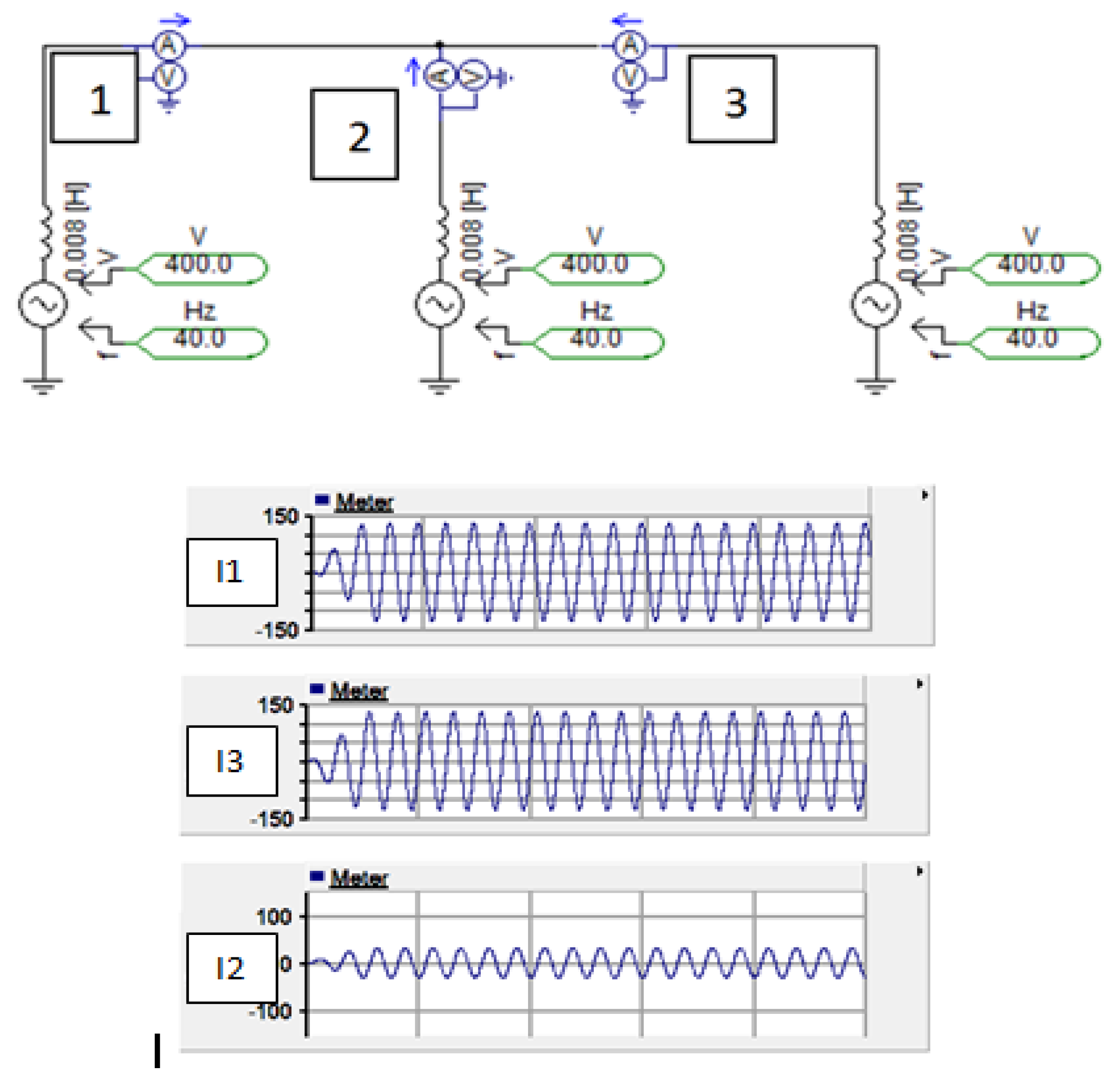
At no load, the adjacent coils, which belong to the same phase, are connected in parallel. The induced FEM are not synchronous and circulating currents exist. In this example, three coils are connected (1, 2, and 3) and the circulating currents I1, I2, and I3 are plotted. They can be as high as 30% of the rated current and are not visible in power supply lines.
Machines 04 00002 g006
Figure 7. Three coils (in blue) are connected in series. The connections (in white, A) show that they take some space in the area used to place circles (in red, B and in green, C). There are four circles, two more than in the figure, one for each phase and one for the neutral. In this figure the cross-sections are small in order to clearly show all of the items.
Machines 04 00002 g007
With this example (Figure 4, Figure 5 and Figure 6), it appears that solutions, where the coils belonging to the same phase are adjacent and are set in parallel, are not acceptable solutions. Hence, designers must verify all of the induced voltages back EMF, for each coil, to avoid connections providing circulating currents. Doing so, some configurations are put away as they cannot be connected to a three-phase power supply without issue.
The geometrical properties of a winding have an important impact on the mechanical behavior. Designers have always paid attention to the force induced by the unbalanced magnetic pull [24,25]. This phenomenon occurs when the rotor is not well centered in the stator. The air-gap is different along the circumference. Subsequently, a magnetic force appears, it induces vibrations and can damage bearings. Unfortunately, this problem is more critical in FSCW [
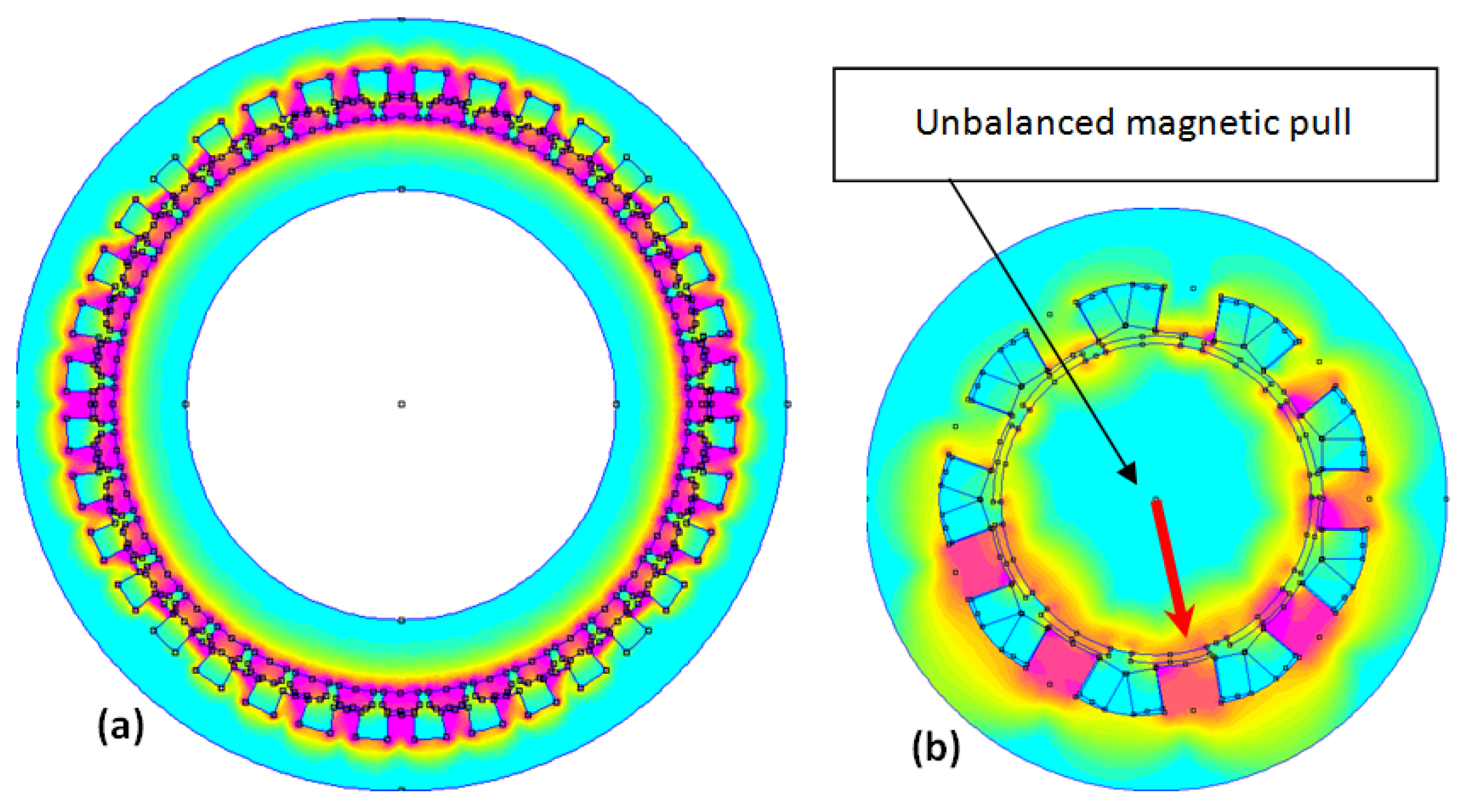
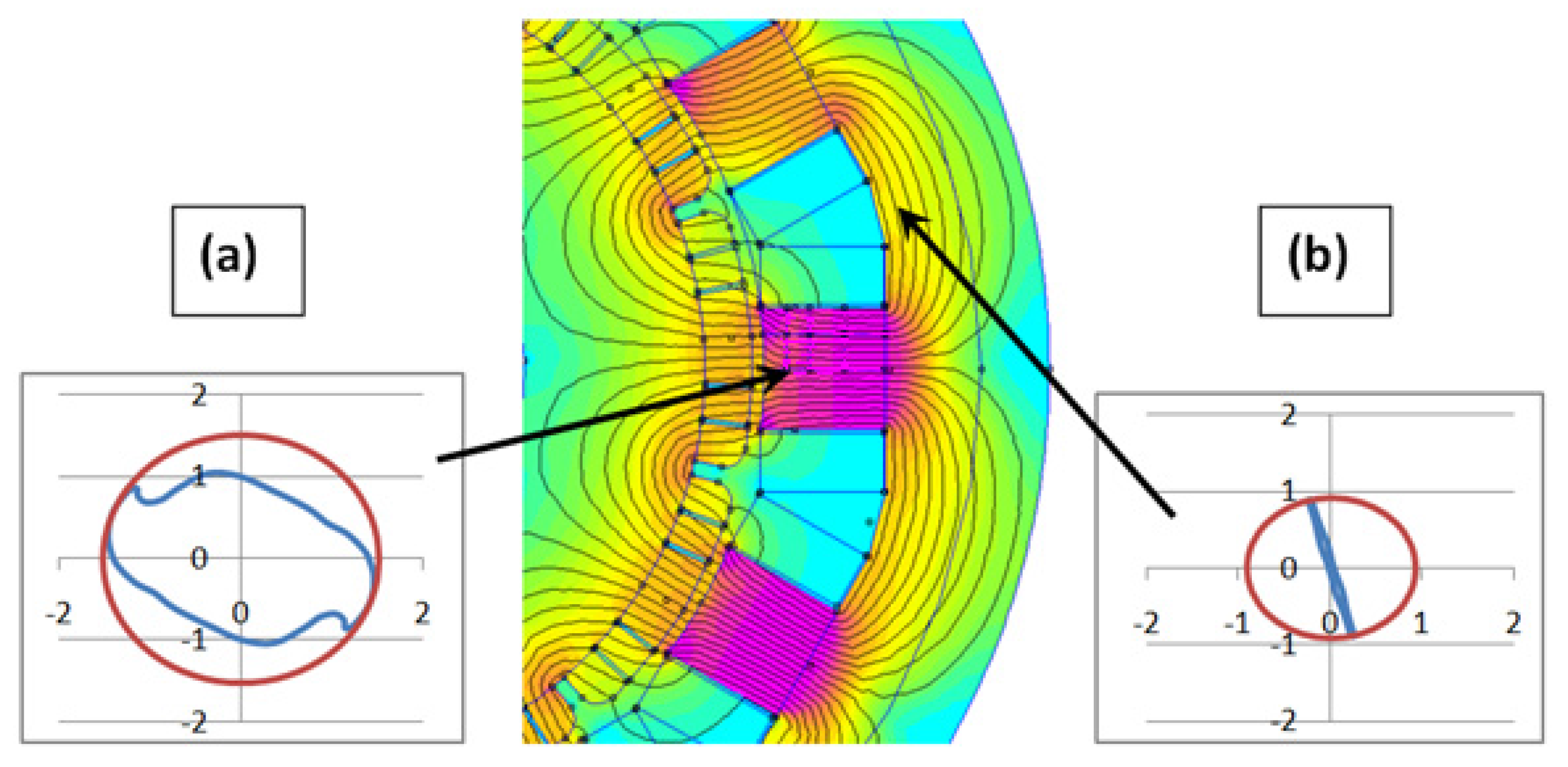
26]. Even if the rotor is centered in the stator, the winding geometry can affect the stability. Let us examine this with the same example, an electric generator having 36 slots and 40 poles. At no load, it appears that magnetic forces are balanced (Figure 8a). This winding structure is coming from the basic structure having 10 poles and 9 slots, but this basic structure, 10 poles and 9 slots, is not mechanically balanced (Figure 8b). This phenomenon has a particularity in FSCW as it can appear even if there is no geometrical deviation during manufacturing. Such a structure has situations that give unbalanced magnetic pull, which is not the case with distributed windings.
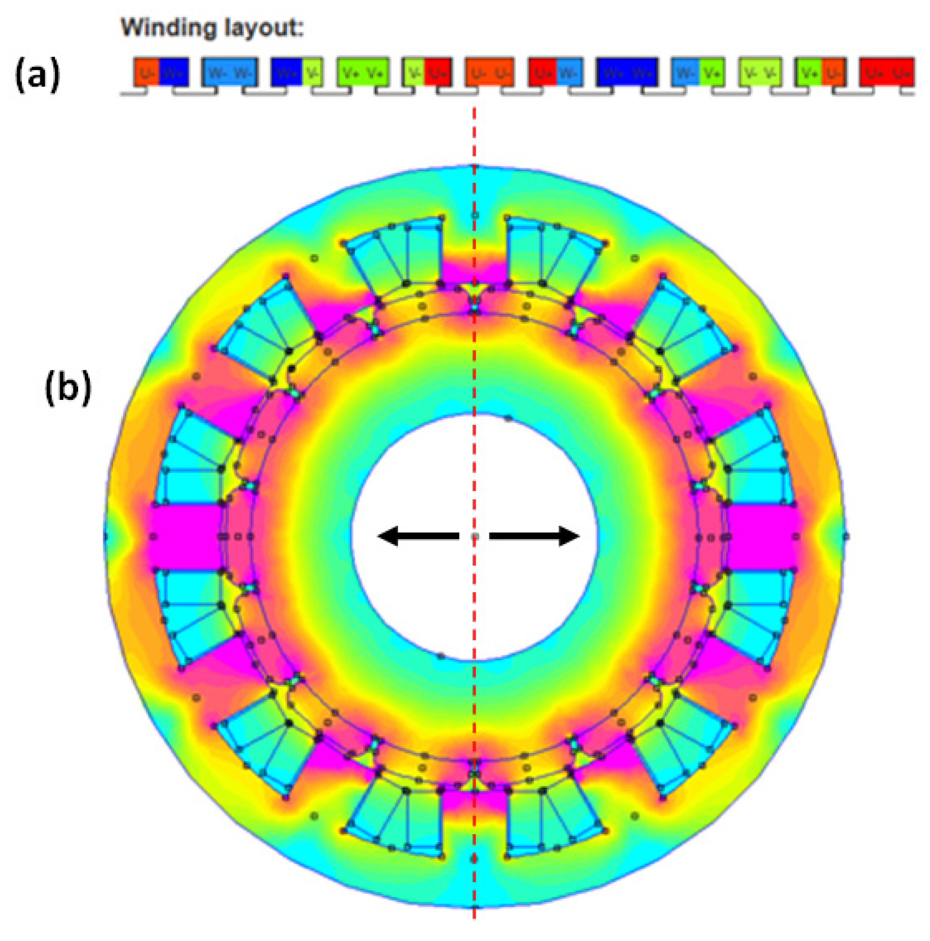
Such a problem can be solved if the winding structure is a duplication of another structure. With this rule, some acceptable structures will be put away. Designers have to verify the magnetic flux distribution at no load and its symmetry. With the structure having 14 poles and 12 slots, which is not a duplication of a smaller structure, the simulations show that flux distribution does not provide any unbalanced magnetic pull. In Figure 9a, the winding layout is described and there is no copy. In Figure 9b, the magnetic flux distribution is shown and there is symmetry. Nevertheless, the structure with 14 poles and 12 slots is an interesting solution in term of magnetic flux distribution, but is not an acceptable solution as there are two coils of the same phase that are adjacent (see winding layout in Figure 9a). With a three phase power supply and having coils in parallel, high circulating currents will appear between coils.
Figure 8. On (a), the distribution of magnetic flux in a 36 slots 40 poles structure at no load. There is no unbalanced magnetic pull; On (b), the distribution of magnetic induction in a 9 slots 10 poles structure at no load. There is an unbalanced magnetic pull as there is no symmetry in the distribution.
Machines 04 00002 g008
Figure 9. In (a), the winding layout of a 12 slots 14 poles structure is presented; in (b), the magnetic flux distribution is shown. Due to the symmetry, there is a no unbalanced magnetic pull, but a possibility of circulating currents when winding layout is observed.
Machines 04 00002 g009

5. Multi-Star and Multi-Phase Winding Structure

The multi-star winding structure is a solution that should be considered when the motors or generators are associated with power electronic systems. This technology has many advantages. The total power can be divided into equal parts that correspond to the unit power rating of the electronic devices. For example, for large motors that are controlled by power inverters, the use of multi-phase and multi-star structure provides an economically acceptable solution [27]. The winding design is not a trivial job, but when the machines are controlled by inverters, multi-phase and multi-star structures are allowed and they can validate the solutions that have been rejected in the previous sections.
The stator which has 14 poles and 12 slots comes back into the list of acceptable solutions. The windings can be divided into two stars that are separated by 30° electrical degrees (Figure 10). Nevertheless, there remain some drawbacks when such machines are coupled to inverters. It is well known that double-star machines are subjected to current ripples in the power line [28]. To reduce these current ripples that strongly depend on the mutual inductance between stars, inductors are added into the power line. Such a solution increases the synchronous reactance and the voltage drop in the full-load case. Moreover, designers should keep in mind the economic aspect of solutions. Although the converters have introduced more degrees of freedom, the solution with multi-star windings and the solution with multi-phase windings, do not have the same cost. The solution, using the three-phase multi-star structure, is the most widespread structure because it uses the existing and well proven power electronics of three-phase devices. The power electronic devices that may be used in the case of a five-phase generator are custom devices. If the multi-phase solution does not include the multi-star structure, there is a lack of reliability. The multi-star windings provide machines that are naturally fault-tolerant. Using an example, this will be enhanced: a synchronous motor rated at 45 MW with four stars, and three phases in each star, is able to operate at full power with only three stars and it remains within the Class B thermal limits [6]. Hence, the use of multi-star windings is a solution to be examined when the motors or generators are coupled to power converters. They can solve winding problems.
Figure 10. The layout of windings associated to the structure having 12 slots and 14 poles. It can be split into two three-phase stars (a,b) which are shifted, electrically, by 30°. Thereafter, this machine is a true conventional double-star machine.
Machines 04 00002 g010

6. Concentrated Winding and Mutual Inductance

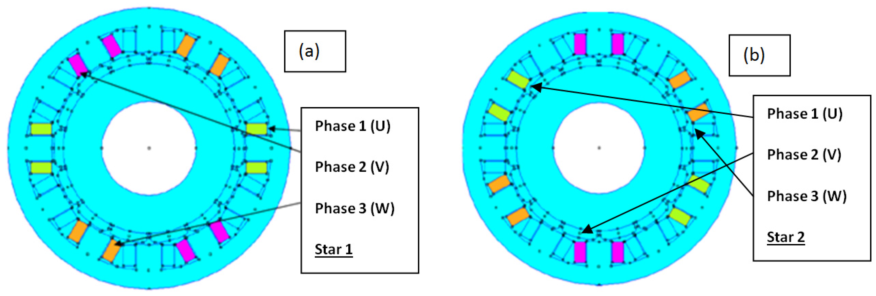
When a d-q model of a double-star winding is observed, it appears that stars are not magnetically decoupled. In Figure 11, the most important parameters are: Lσm and Lσ1 or Lσ2 as it will be shown here after.
In the distributed winding, Lσm is not negligible in front of Lσ1 or Lσ2. It means that a current circulating in one star has an effect on the second star. This is especially verified when commutations of power switches occur. A commutation occurring in the first star generates a peak of current in the second star. Current ripples are thereafter observed. To reduce such a phenomenon, it is possible to increase Lσ1 or Lσ2 in adding inductors in the power line, as it has been suggested at the beginning of this section. In the distributed windings, it is usual to find that more than 30% of the magnetic flux of the first star is present in the second star. It implies a high value for Lσm and a low value for Lσ1 or Lσ2. Regarding FSCW, the situation is not similar [29]. The effect of the current in one star can be neglected in the other star. Moreover, with a simple rule described in this previous reference, evaluation of mutual effects can be achieved.
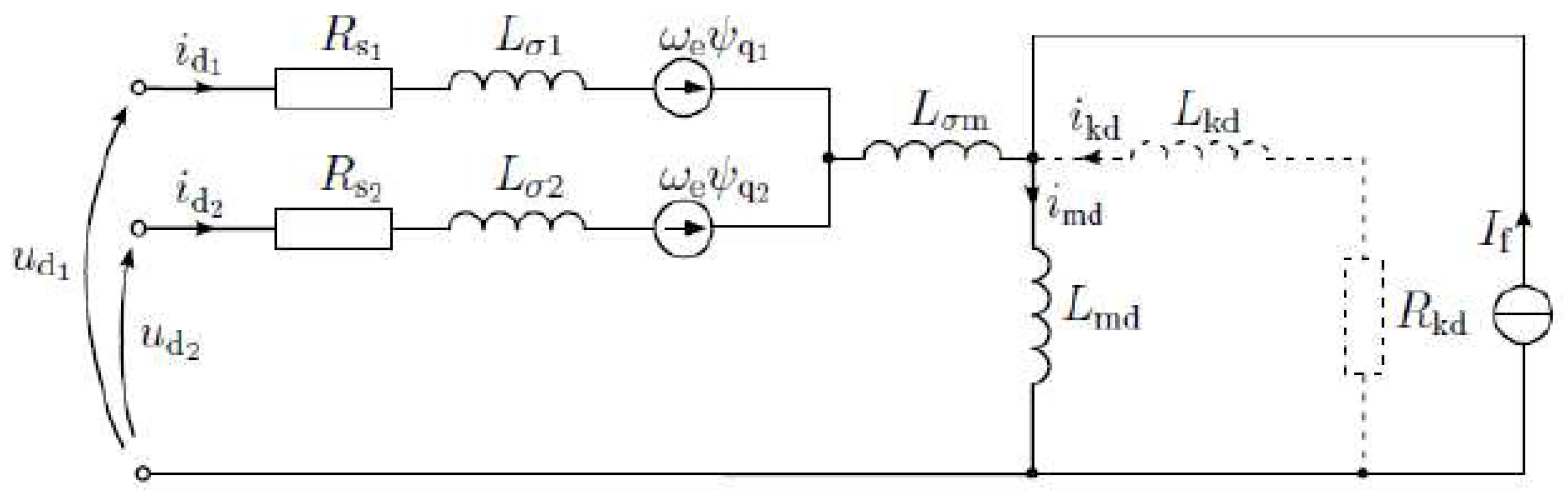
Figure 11. The equivalent model in d-q scheme of a double-star synchronous generator.
Machines 04 00002 g011
Simulations and methods have been developed by Tessarolo to calculate the equivalent model associated to machines having multi-phase and multi-star windings [6]. Using these methods for the designed structure (12 slots, 10 poles), it can be concluded that the mutual inductance between stars is low; the Table 1 confirms this important point.
Table 1. Numerical results obtained for a designed FSCW structure having 12 slots and 10 poles.
Lσ10.23 mH
Lσ20.23 mH
Lσm0.006 mH
As Lσm is very small in front of Lσ1 or Lσ2, the currents in the first star do not have any influence on the second star. Moreover, Lσ1 and Lσ2 have the greatest value allowed by the geometry of the machine. Any increase in Lσ1 or Lσ2 is only possible by inserting inductors in the supply power lines. Such a magnetic independence is not always found in other publications [30]. Differences can be observed and also explained. When the slot is not fully open, which is not the case in our design the magnetic flux can use the slot depression as magnetic path. Hence, this leakage flux is the main origin of the mutual inductance between stars [29]. Even if the increase of the slot opening is not recommended, as it causes additional losses in the rotor, this configuration is not prejudicial because some methods exist to mitigate magnet losses. Recent publications show that modeling of the multi-star machines is always in interest of the researchers [31].

7. Concentrated Winding and Flux Circulation in the Stator

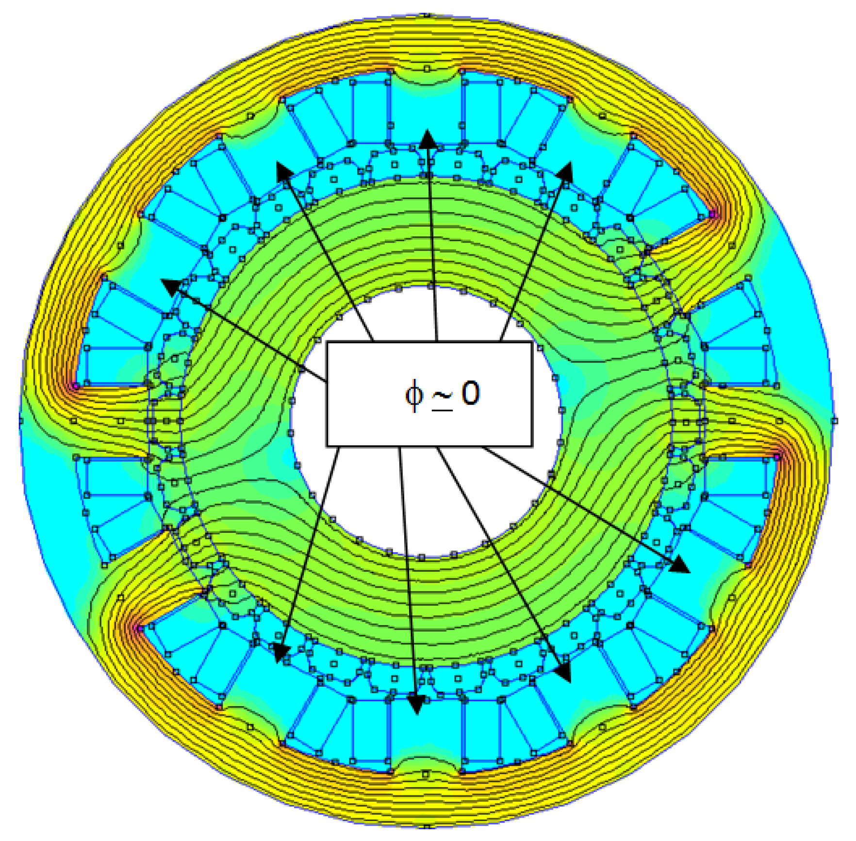
Within the result of the simulation presented in Figure 12, an interesting property is underlined. The magnetic flux follows the back-iron core in order to close the magnetic loop. Its value into the adjacent teeth is low. This means that the back-iron core is the main path for the magnetic flux coming from the coils. The studied structure is a high-polarity machine. Traditionally, high polarity machines are designed with a stator iron core with low thickness, this rule is not always a good rule for the FSCW. This point of view can be explained with an example. In 
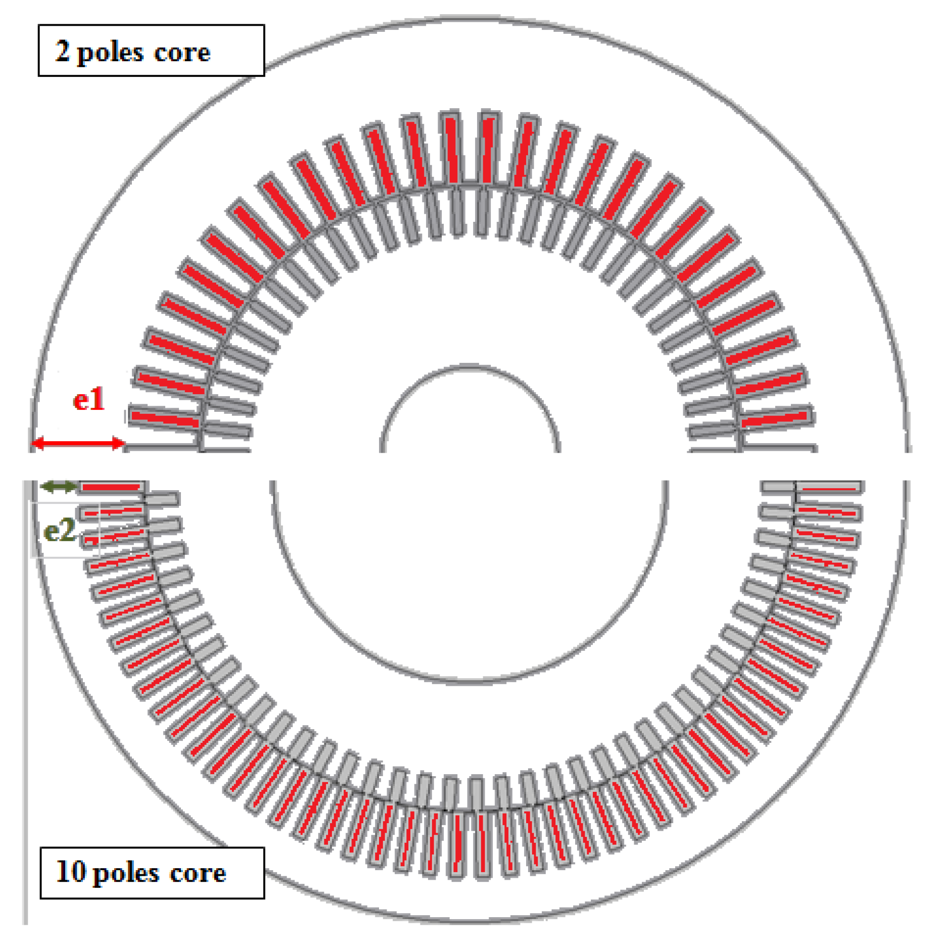
Figure 13, two traditional structures are presented, the first one, is a 2 pole asynchronous motor and the second one is a 10 pole asynchronous motor.
Figure 12. Structures of the active part of a 26 pole 12 slot generator that uses FSCW. With four coils powered and no MMF in magnet, the flux uses a large area of the stator back iron as main path to close the magnetic loop.
Machines 04 00002 g012
Figure 13. Schemes of the active part of a 2 pole motor compared to the active parts of a 10 pole motor. e1 and e2 are the back-iron core thicknesses (e1 >> e2) and both of them use distributed windings.
Machines 04 00002 g013
The design engineer knows that flux circulation in a two-pole machine uses the whole part of the stator back-iron to close the magnetic loop. With a low thickness in the back-iron core, the performances of the motor would not be acceptable. The two-pole machines have great power factor (greater than 0.9), but it cannot be sustained if the thickness of the iron core decreases. A 30% decrease in thickness is enough to get a power factor similar to an 8 pole machine. Hence, even if motors using FSCW are generally high-polarity machines, their iron core stator should not be designed with the same traditional scheme. It is a reason why, when comparisons are done, the machines using FSCW are afflicted by the worst efficiency, they have more losses, and iron losses are higher [3]. In this reference, the authors have designed two machines with the same power (80 kW) and the same speed (300 rpm). The first one uses FSCW and the second one uses a distributed winding. As the thicknesses of the cores are very similar, even if the copper volume of the distributed windings is twice the copper volume of FSCW, the efficiency of the machine having concentrated windings is less than the efficiency of the machine having distributed windings. Thereafter, looking at the power factor, it appears that the power factor concerning the distributed windings is 0.86, which is better than the power factor associated to the concentrated windings machine, which is only 0.78. The design of the stator iron core is important and designers must also pay attention at the magnetic flux in the teeth. The reason can be found in observing a simulation of the magnetic flux distribution in the tooth. An effect appears: the tooth acts as a magnetic short circuit for the magnets during their rotation (Figure 14). This leakage flux, similar to zigzag leakage flux, has a second effect when the slots are open; the magnetic flux in the tooth has a rotational behavior.
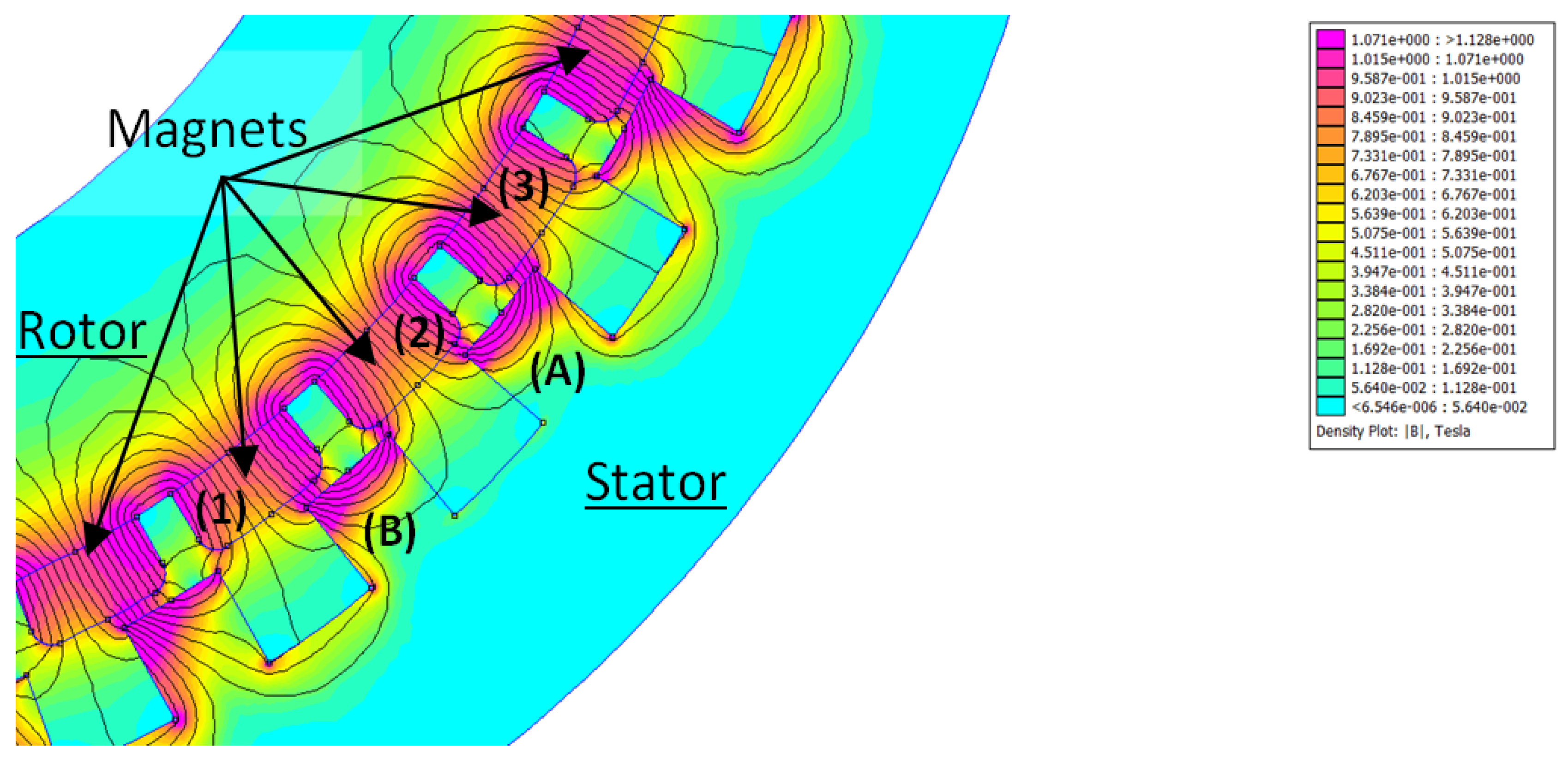
Figure 14. In this partial view of a machine having 40 poles and 36 slots; it appears that the magnetic flux in the top of the teeth (A and B) will never be zero. When the magnets of the rotor (1, 2 or 3) are not in front of the tooth, the tooth is acting as a magnetic short circuit.
Machines 04 00002 g014
In this example, there is a part of the tooth where the flux is rotational and the iron losses must be calculated with caution. The iron losses can be underestimated if the suitable formulations are not used. In fact, two working cases have to be taken into account, The first one is the phenomenon described in Figure 12, which is the magnetic flux circulation induced by the current in the coils, and the second one is the flux circulation induced by the permanent magnet in the teeth which is shown in Figure 14. Within our studies at no load, it appears that about 45% of the iron losses are in the back-iron and about 55% in the teeth. These losses will increase with magnetic induction. There is nothing to do to decrease the iron losses in the teeth but it is possible to decrease the losses in the back-iron by using a greater external diameter. Doing so, the thickness of the back-iron increases and it looks like to the back-iron of a lower polarity machine. Moreover, the methods used to calculate iron losses have to be adapted [11]. In the distributed windings, the Finite Elements Method is used as a regular method and some researchers have used this method and have investigated the impact of rotational magnetic fields in these machines [32]. As the rotational behavior does not significantly alter the iron losses calculation, the regular method has not been enhanced. In our case, the permanent magnet generators used in variable-speed operations also have frequencies that differ wildly from 50 or 60 Hz. Hence, data about iron losses in the magnetic steel have to be determined with measurements and tests, as they are not always provided as usable data by manufacturers [33,34,35]. As a conclusion, designers have to integrate a lot of information in their designs and have to adapt the losses calculation. It remains that iron losses are important in FSCW. This explains why the magnetic steel used is sometime the 35RM300 grade in order to decrease the iron losses.

8. Rotor and Magnet Losses

The magnets which are mounted on the surface of the rotor are subject to eddy current losses [36]. Methods of calculation are accurate in distributed windings [37]. Such methods are not so convenient for FSCW. With the same stator, it is possible to build more than one machine. For example, a stator having 12 slots can be coupled to a rotor with 10 poles or a rotor with 14 poles. As the number of slots is close to the number of pole, these machines have a high winding factor, 0.966 for single layer and 0.933 for double layer. The air-gap has many magnetic field harmonics with which both rotors can synchronize. Even if this can be considered as an advantage and versatility for the structure, the magnetic field harmonics, which are not synchronized with the rotor speed, induce eddy-currents in the magnets mounted on the rotor and they increase the magnets’ temperature [38,39]. The choice of the combination of the number of poles and number of slots can increase or decrease the losses in permanent magnets as it acts on the harmonic content in the air-gap. The suitable value for slot/pole.phase which decreases magnet losses will not be this the one which gives the highest winding factor [
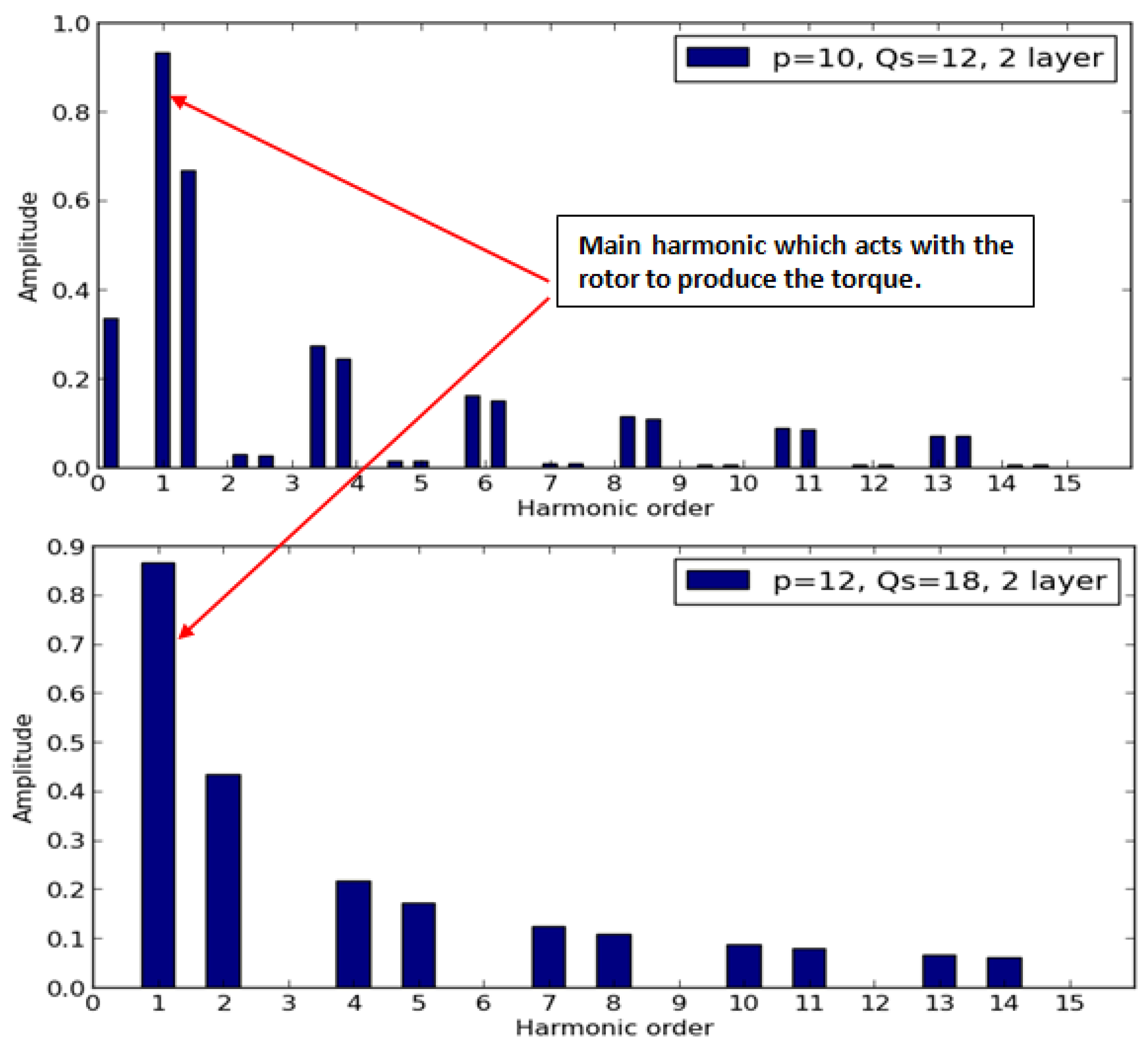
40]. The two requirements are not straightforward. As it appears in Figure 15, the 12 poles/18 slots structure has fewer harmonics than the 10 poles/12 slots structure. Hence, losses caused by eddy currents in the magnets are the lowest [41]. Unfortunately, the winding factor associated to the main harmonic (number 1 in Figure 15) is not the highest. It is usual to consider that the best choice, regarding magnet losses, is q = 0.5, with a small decrease in winding factor (Table 2).
It is possible to set the magnet losses to zero. The progress in bonded magnets is regular and they can be used in place of sintered magnets. Nevertheless, their characteristics, such as Br of Hc, are inferior. Such a solution can be used only if a decrease in magnetic flux is accepted [42]. Another solution consists in decreasing the strength of the magnetic flux harmonics to keep the temperature of the magnets under the highest temperature of use (Table 3). Losses in the magnets are not the main source of losses. They do not really modify the efficiency of the machine, but they can damage the magnets if the temperature remains above the maximal allowed temperature. The first damage is a decrease of Br and Hc. This phenomenon is characterized by coefficients which are always negative [43].
Figure 15. Amplitude of MMF in the air-gap as a function of harmonic rank. Even if the 12-pole/18-slot configuration has fewer harmonics, amplitude of its main harmonic is lower than the amplitude of the main harmonic of the 10-pole/12-slot configuration.
Machines 04 00002 g015
Table 2. Comparison between the winding factors of two machines having different number of slots per pole per phase.
Main Characteristics
12 slots/10 poles18 Slots/12 poles
q = 0.4 (Slot/Pole. Phase)q = 0.5 (Slot/Pole. Phase)
Kw = 0.933 (Winding factor)Kw = 0.866 (Winding factor)
Table 3. Magnet, Temperature of use (Max).
Main Characteristics
Ferrite280 °C
AlNiCo540 °C
SmCo300 °C
NdFeB80 °C
Unfortunately, the NdFeB is a magnet having the highest level of energy density and it is three time more sensitive to the temperature than the SmCo magnet. The reversible temperature coefficient (RTC) of residual induction, Br, is only about −0.035%/°C for SmCo based magnets as compared to −0.110%/°C for NdFeB based magnets [44,45]. Usually the NdFeB magnets are called: magnets for room-temperature applications. The technology of magnets is always in evolution. Even if the recent NdFeB technology reaches the practical performance limits in stored energy (510 kJ/m3), improvements in temperature tolerance are in progress with the use of another rare-earth material: dysprosium. Therefore, machine designers should not limit their designs compared to the magnet capabilities; they can evolve in a short time. Selecting the magnets which accept a high working temperature is not always a good solution. This means that the rotor would accept a greater operating temperature and the losses will always exist. The solutions that decrease losses must be preferred. Two methods have been examined. The first one is based on the winding layout. Some researchers are working on asynchronous machines which are using FSCW [7], the magnetic field harmonics in this machine are not acceptable and any progress in this domain will be a benefit for both synchronous and asynchronous machines. The second one focuses on the magnets. The sintered magnets are segmented and that will reduce the effects of eddy currents [46]. The solutions that have been developed here is based, in part, on the winding layout: the use of the double-star structure. Such a structure is able to decrease the magnetic flux harmonics in the air-gap and also enhances the winding factor. Nevertheless, the use of the double-star structure is only possible if the slots are totally open [29], and opened slots do not have a good influence on the losses in the magnets [47]. The issue will be discussed later.
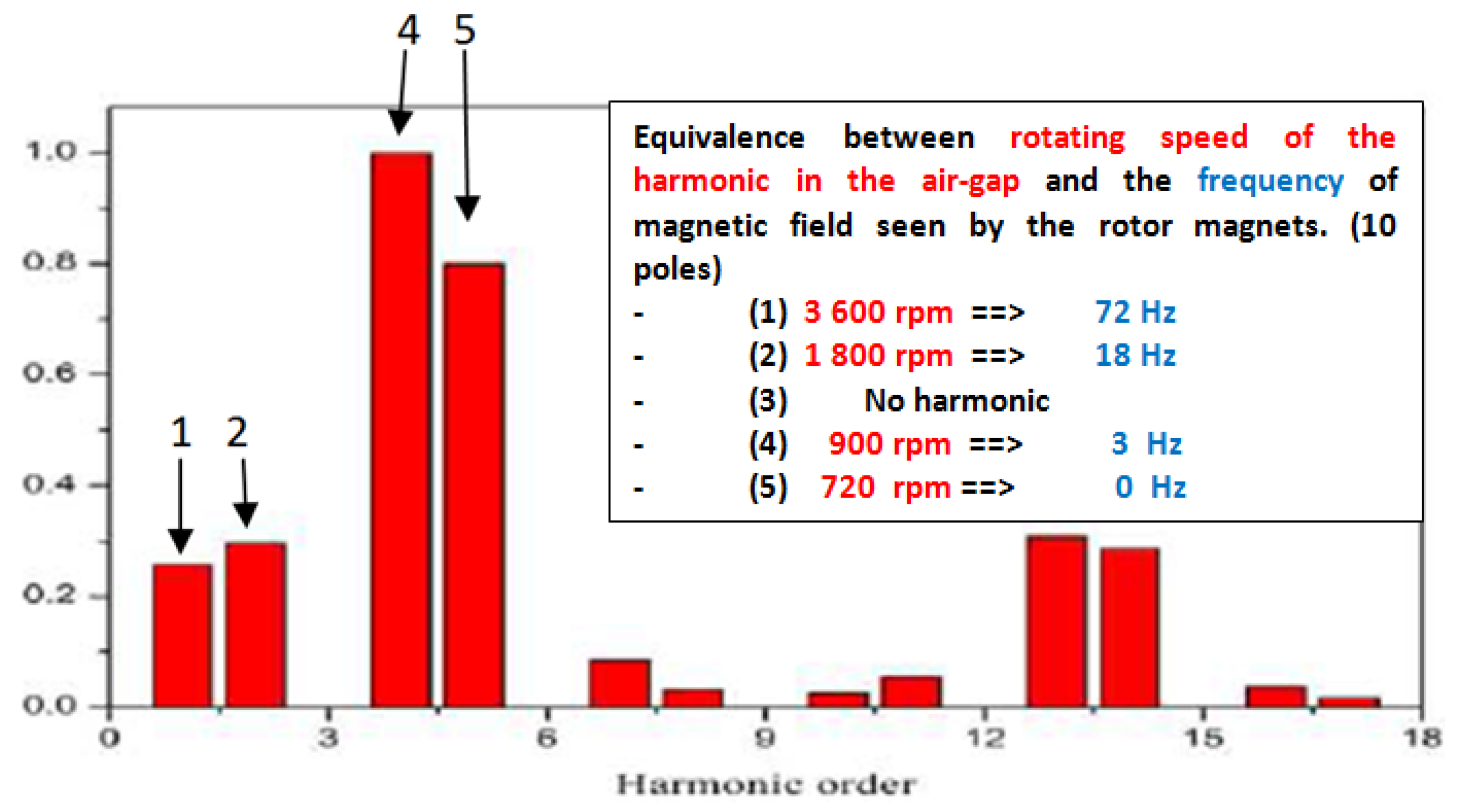
As it will be highlighted, the most dangerous harmonics are harmonics which rotate at high speed in front of the rotor speed. It means that the undesirable harmonics are the first, below the main harmonic which produces the torque. For example, in 
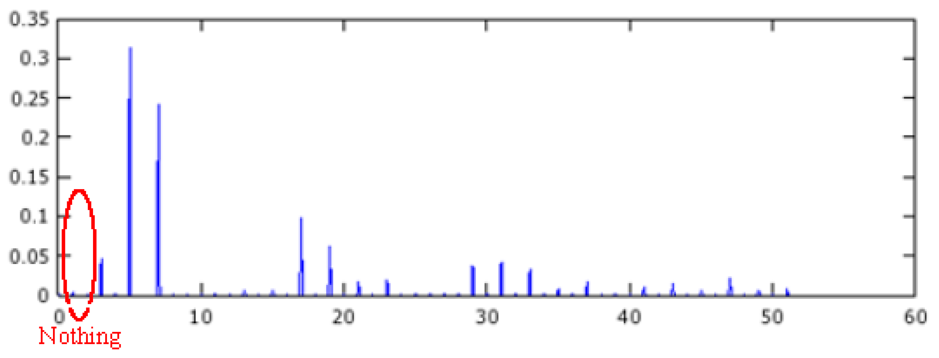
Figure 16, the spectrum of MMF in the air-gap is represented. The main harmonics are used to provide an 8-pole or a 10-pole machine. If this machine is supplied by a 60 Hz power line, the rotor can rotate at 900 rpm (8-pole) or 720 rpm (10-pole). The first harmonic rotates at 3600 rpm and the second at 1800 rpm. Hence, for a 10-pole motor, the first harmonic is seen, by the rotor, as a rotating field running at 4320 rpm. For an observer which is link to the rotor, such a magnetic field is seen as a variable magnetic field which frequency is 72 Hz. The high order harmonics, greater than eight, are seen as magnetic fields with low rotating speeds and also having low amplitudes. The main goal is in the reduction of the harmonic amplitudes below the main harmonic, as they involve high losses in the magnets supported by the rotor. A harmonic which is close to the main harmonic can be an issue for the magnet losses. Its amplitude is high and it cannot be suppressed; its presence is a specificity of the FSCW.
Figure 16. The amplitudes of magnetic field harmonics in the air-gap selected by rank in a 9-slot structure. The two main harmonics (four and five) can provide an 8-pole machine or a 10-pole machine. For a 10-pole machine, the harmonics of magnetic fields generate variable magnetic fields for the rotor. Their frequencies, for an observer link to the rotor are given in the upper part of the figure (10-pole). Notice the null frequency for the harmonic five, the rotor is synchronized with it.
Machines 04 00002 g016
Using simulations, it appears that MMF harmonics, especially the low-order harmonics can be mitigated by using a double-star winding structure. To demonstrate this property, the machine having 14 poles and 12 slots is supplied by two different methods. In the first one, the two stars (Figure 10) are fed by two three-phase power supplies which are synchronous. With these power supplies, the FFT of the MMF in the air gap is presented in Figure 17. As it is expected, the harmonics five and seven are the most important harmonics as they provide a machine with 10 poles and a machine with 14 poles, the harmonics one and three are not negligible.
Figure 17. The amplitudes of MMF harmonics in the air-gap. The 12-slot structure is fed by two three-phase supplies. The currents are synchronous.
Machines 04 00002 g017
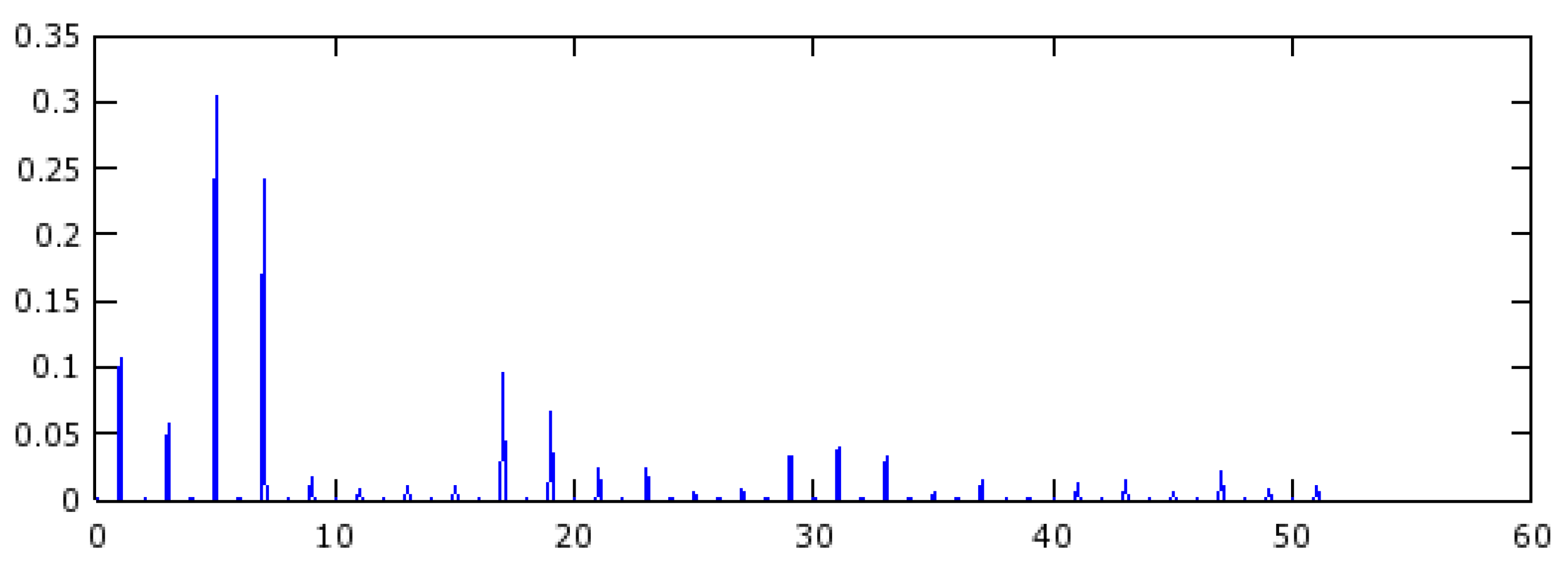
Now, the 12 slots structure is supplied by two three-phase supplies which are shift electrically by 30°. It is a true double-star machine. The FFT of the MMF in the air-gap is presented in Figure 18. It appears that the first harmonic has vanished. Using an electrical supply that is adapted to the magnetic structure of the machine can have a positive impact on the losses.
Figure 18. The amplitudes of harmonics of the MMF in the air-gap. The 12-slot structure is fed by two three-phase supplies shift electrically by 30°. The first harmonic has vanished.
Machines 04 00002 g018
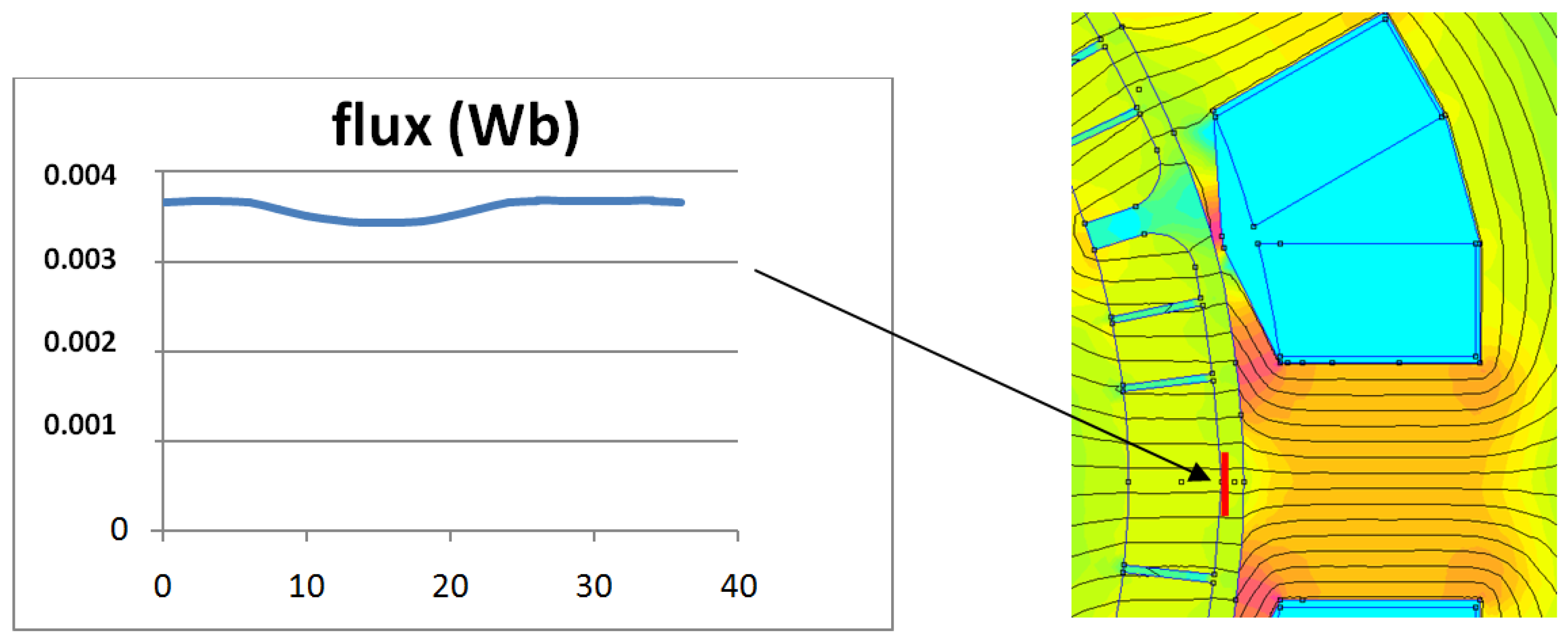
It is time to investigate the influence of slotting for magnet losses. Such a phenomenon is well known in distributed winding [
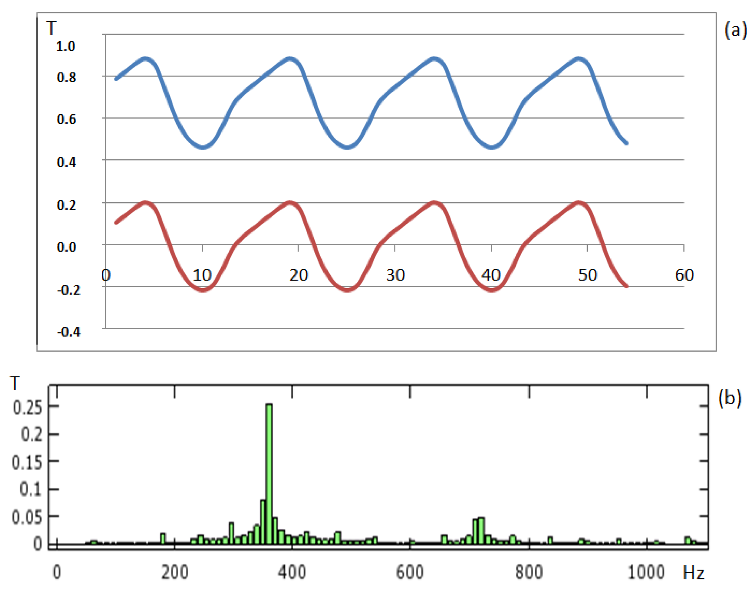
48]. It can be more important with FSCW. When the intensity of magnetic flux is calculated through the surface of a magnet during the rotation of the rotor, a variation appears. In the Figure 19 and Figure 20, two slot shapes are compared. In Figure 19, the slots are closed and the evolution of magnetic flux on the surface of one magnet is not highly dependent on the rotor position. In 
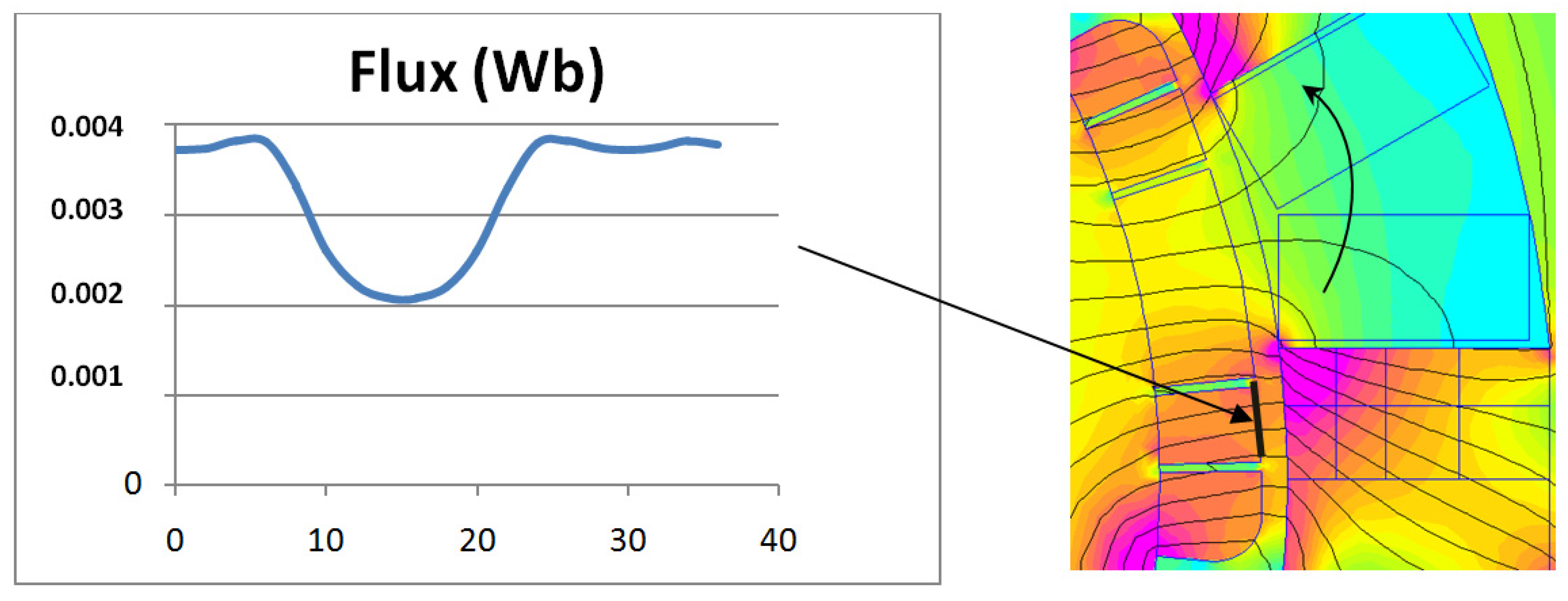
Figure 20, the situation is different. A high level of flux fluctuations is visible; such fluctuations can be observed in axial flux machine where the slots are opened [49]. This phenomenon will induce eddy currents in the magnet and this fluctuation is high enough to generate eddy currents which will exceed the losses associated with the MMF harmonics in the air-gap (Figure 18). For example, using Figure 20, the magnet is subjected to a variable magnetic flux which intensity is 0.2 T and its frequency is 600 Hz if the rotor rotates at 3000 rpm. In front of such a phenomenon, the opened or closed slots will remain an issue. With the closed slots or half-closed slots, the permanence of the magnetic circuit attached to the magnet is constant, but there is a high level of magnetic flux leakage, both for the magnetic flux generated by the magnets and for the magnetic flux generated by the coils. In one of our simulations, 15% of the flux provided by the magnets flows through the slot depression and 30% of the flux provided by the coils also flows through the slot-depression. They are leakage fluxes that do not provide torque. They only generate losses. With opened slots, these leakage fluxes are drastically minimized. The use of opened slots has allowed the use of multi-star structures as it suppresses the magnetic coupling between stars. Unfortunately, this use also provides drawback: magnetic flux ripples are increasing in the air-gap and the rotor losses, especially the magnet losses, must be managed.
Figure 19. At no load, the rotor position is increasing step by step (0° to 36°). For each position, the flux on one magnet surface is plotted. As the slots were closed, the slot depression mitigates the permeance variation and the flux remains nearly constant.
Machines 04 00002 g019
Figure 20. At no load, the rotor position is increased step by step (0° to 36°). For each position, the flux on one magnet surface is plotted. The slots are opened, there are high permeance variations, and the flux in the magnet is affected by high fluctuations which induce eddy currents.
Machines 04 00002 g020
The losses generated by the eddy currents are harmful for magnets. The usual solution is in the segmentation [42,50,51]. Such segmentation is also a good solution when the machine, acting as generator, is used to feed a rectifier load. This load provides a high level of current harmonics [17], as summarized in Table 4. The magnets segmentation can be optimized with regard to the number and the shape of the magnets [52,53,54]. In many articles, the losses associated to this flux tooth ripple are not considered. In the studies of machines that use FSCW, the slots are half-closed or closed. Flux tooth ripple is mainly treated in permanent magnet machines which often rotate at high speed or in axial flux machines. Authors of articles that concern such machines do not recommend a subdivision of the problem. If the harmonic losses and tooth ripple losses are calculated with two separate methods and are added at the end of the design, the total losses will not be accurate. In our case, the most important effect is caused by the flux tooth ripples. Nevertheless the design of the magnet will be done with a global method. Hence, the effects of any eddy currents are minimized (those coming from tooth ripples and those coming from MMF harmonics). Moreover, doing simulations which are time consuming to calculate eddy current losses is not realistic in pre-determination of a machine. There is no need to involve 3D simulations; losses which are calculated are limited to eddy-current losses. Simple studies that are using 2D simulations and analytic calculations can provide usable results. Designers have to know that hysteresis losses also exist in the magnets and they are not considered here [55].
Table 4. The segmentation of magnets and its impact on losses mitigation when the machine acts as generator and feeds a rectified load (Results reproduced with the permission of the authors: D. Gerling [52]).
Number of Magnet SegmentationLosses Decrease in%
1 (no segmentation)0%
280%
3>90%
4>95%
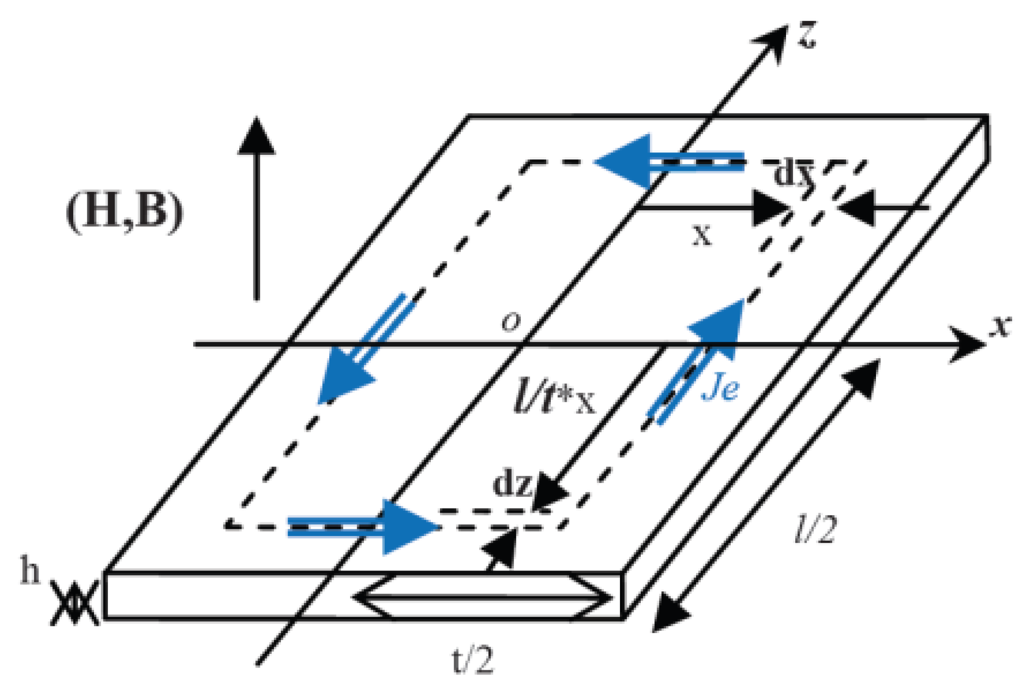
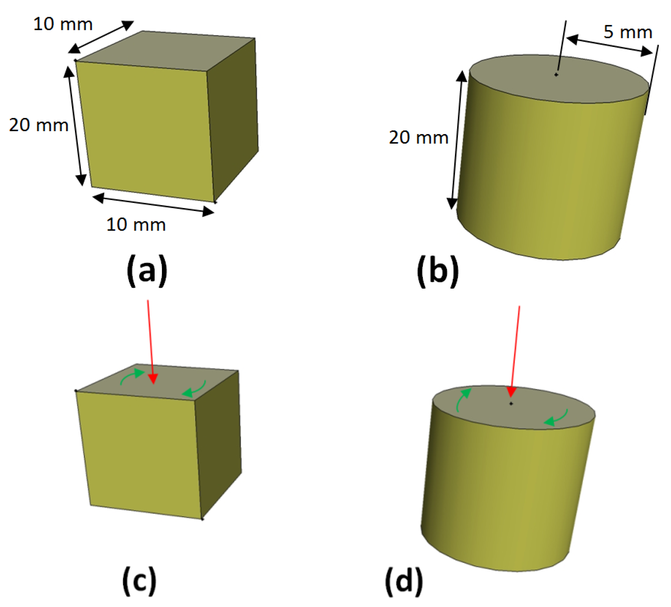
Segmentation is a straightforward method which also reduces the difficulties of calculation in loss evaluation. The magnets are good electrical conductors and are subject to eddy currents. The segmentation transforms large conductive volumes into small volumes. Hence, doing so, these volumes also are small in front of the skin effect. Losses per unit volume can be evaluated using the conventional Equation (1) which does not require a 3D simulation [56], f is the magnetic field frequency, Bm is its peak strength, ρ is the electrical conductivity of the medium and t and l are geometrical parameters described in the Figure 21.
P e d d y =   π 2   f 2   B m 2 8   ρ . t 2   l 2 ( t 2 + l 2 )
Such analytical formulation can provide good evaluation for magnet losses as long as it is used in suitable situations. Hence, such a loss calculation must be verified to provide a sufficient accuracy in evaluation of machines efficiency. In the Subsection 9.5, a brief study is done to validate the method.
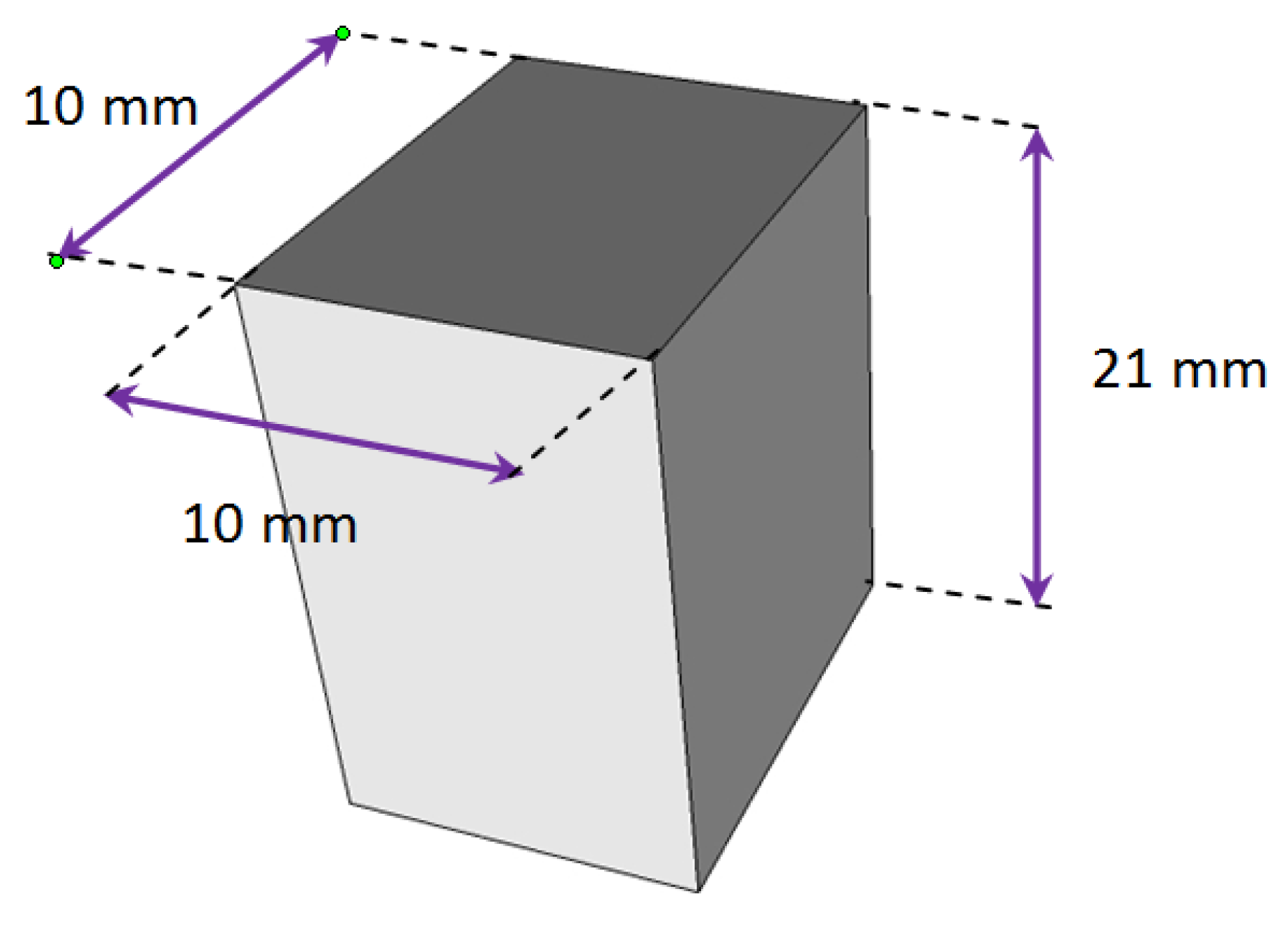
Figure 21. Scheme used for the calculation of eddy currents losses in a conductor sheet in case of neglected skin effect. This means that the thickness of the sheet is small in front of the skin depth.
Machines 04 00002 g021

9. Application of Rules in Design of a Permanent Magnet Generator with Fractional Slot Concentrated Winding

The specifications come from an industrial case, with an imposed volume (Table 5); the goal is to design a magnetic structure which uses FSCW. The efficiency must be as high as possible.
Table 5. Specifications.
Stack Length (core)≤300 mm
Diameter (external core diameter)≤850 mm (can be modified)
Overall length (with coils)≤400 mm
EfficiencyAs high as possible
The rated power is 670 KW and the voltage is 280 V (Ph-N). The number of phases and the number of stars are not imposed and some requirements have to be considered (Table 6). The magnets must be Sm-Co magnets and the air-gap must be greater or equal to 5 mm. The speed is 1800 rpm and the machine should be controlled by a converter. The machine can act as motor or generator. Such a type of generator has already been studied in 2005, but it does not use FSCW and even if it is a six-phase machine, the rotor has field winding and does not support magnets [57]. The same year, another study is done about a permanent magnet generator for naval application and the author underlines that the architectures of these machines are not limited to 50/60 Hz and, thereafter, higher operating frequencies can be used [58].
Table 6. Requirements.
ParametersUnitsValues
Electrical PowerKW670
Voltage (Ph-N)V280–300
Electrical steel graden.a.M 400–50A
Magnet Materialn.a.Sm-Co30 MGOe
Rotational SpeedRpm1800
With such a specification, the study evolves toward a double-star machine, with 30° electrical shift between stars. This solution can provide a machine with number of poles (Np) and number of slots (Ns) which fit with the design rule: Np-Ns = +/− 2, (Table 7). The coils definition is given in Table 8.
Table 7. Machine structure.
ParametersUnitsValues
External diametermm825
Stack Length (core)mm260
Overall length (with coils)mm400
Number of slotsn.a.12
Number of polesn.a.10
Table 8. Windings.
Table 8. Windings.
ParametersUnitsValues
Numbers of turns per coiln.a.11
Numbers of turns per phasen.a.22
Wire dimensions *mm × mm(2.7 × 2.7) × 2 (Copper)
Number of strand in handn.a.20
* See Figure 22 for layout.
Figure 22. Layout of a coil with a sub-division in strands in order to reduce Joule losses provided by the skin effect and the proximity effect.
Machines 04 00002 g022
Advantages of this solution:
-
High winding factor (0.933 with double layer).
-
No circulating current between coils which belong to the same phase.
-
Low level of induction in the teeth (in accordance with the design rule: Np-Ns = +/− 2).

9.1. Study Case

The generator is running at 1800 rpm and the load is a pure resistance. The internal resistance and the internal reactance have been calculated. With these data, a simulation is established in order to provide all the necessary data to calculate the losses presented in the chapter three and summarized in Figure 1. The simulation is for one star and the results are presented in Figure 23 and Figure 24.
Figure 23. Layout of the simulation which provides data for the calculation of losses in all the part of the machine, in this figure, only one star is presented.
Machines 04 00002 g023
Figure 24. Results of the simulation. It can be noticed that voltage drop remains under 10% at full load.
Machines 04 00002 g024

9.2. Iron Losses

The calculation of iron losses at no load and at full load must be done with caution. As it has been highlighted in chapter 7 with Figure 14, the magnetic flux is rotational in the teeth and this behavior must be taken into account. Equation (2) will be used to calculate the iron losses in the stator. The losses per mass unit are the sum of three items. The first one is the hysteresis losses (kh.f.Bα), the second one is the eddy current losses (ke.f2.B2) and the third one is the excess or anomalous losses (ka.f1.5.B1.5). Each item is calculated in one elementary volume (i) of the stator core and mi is the mass of this volume. The last item, ci is the short-to-long axis ratio of the field vector hodograph in the zone (i). It has to be notice that such a parameter is almost equal to 0 in the stator but greater than 0 in the teeth (Figure 25). In summing all these losses on the whole volume of the stator, this provides the total iron losses.
P i r o n = i = 1 n [ m i   × ( k h . f . B + k e . f 2 . B 2 + k a . f 1 , 5 . B 1 , 5 )   × ( 1 + c i ) ]
Parameters: k h   , k e ,   k a which are used in this equation, are particular. The working frequency is not 50 or 60 Hz. Technical data given by manufacturers do not always provide them. Research laboratories have initiated studies which are able to fill the gap. Hence, used parameters come from an article where these authors have studied four different electrical steel grades [34]. Three cases are examined. One with no current in the stator, which is the no load case, and the two others cases are the 3/4 load and the full load. Table 9 summarizes the calculation of losses. The results deviate from the results presented by I. Boldea in his book [11]. The load is seen by the pure voltage source (Figure 23) as an inductive load (cos(ϕ) < 1), doing so, the magnetic field generated by the load current decreases the magnetic induction in the teeth. Even if this can be considered as a good phenomenon for the iron losses, it must kept in mind that such a phenomenon also decreases the voltage provided by the generator.
Figure 25. By = f(Bx) for two different zones of the stator. In the tooth (a) the field is rotating and ci = 0.7 in this example. In the back iron (b) the field is alternating and ci = 0.
Machines 04 00002 g025
Table 9. Losses in the stator (Iron).
ParametersUnitsValues
Iron losses in the teeth (3/4 load)W2209.0
Iron losses in the back iron (3/4 load)W1437.0
Iron losses in the teeth (Full load)W2082.0
Iron losses in the back iron (Full load)W1336.1

9.3. Joule Losses

The terminal voltage of the studied machine is low and the rated current is high. Hence, the cross-section of the copper must be high to maintain the current densities in accordance with the thermal limits of the machine. The frequency is up to 150 Hz and the skin effect cannot be forgotten. The conductor has to be divided into many strands. This method is a conventional method when the skin effect has to be mitigated [59,60]. The layout, presented in Figure 22, is a solution that allows the manufacturing of the coils but does not mitigate the skin effect as enough as wished. An increase in subdivision should be more benefit in spite of the manufacturing capability. To estimate the skin effect, the dimension of one strand has to be compared to the penetration depth (δ) at 150 Hz. In using Equation (3), it appears that the dimension of strands is under δ (δ = 5.44 mm at 150 Hz). With this layout, the skin effects and proximity effects are still not negligible but remain acceptable, the coefficient which link RDC (resistance measured with DC currents) to RAC (resistance at 150 Hz) is 1.94. It means that RAC = 1.94RDC. The calculated Joule losses are presented in Table 10. At full load, even if the current density is low, the skin effect affects the joule losses and a comparison, with conventional machine where the skin effect is less important, should be done with a value multiplied by 1.4. Hence, looking at the full load case, the value which must be used is 2.79 × 1.4 = 3.09 A/mm2. Due to the volume of the machine, this value is low enough to consider a cooling system using air. If an increase of rated power is needed, another cooling system should be used. For example: ring containing circulating cold water surrounding the stator provides the thermal dissipation of the machine.
δ = 2 ω . μ . σ 2
Table 10. Losses in the stator (Joule losses).
ParametersUnitsValues
Joules Losses in the coils (3/4 load)W2036.87
Current density in the conductor (3/4 load)A/mm21.96
Joules Losses in the coils (full load)W4124.97
Current density in the conductor (full load)A/mm22.79

9.4. Mechanical Losses

Ball bearings and sleeve bearings bring mechanical losses. They are very small in front of the iron or Joule losses. If ball bearings are selected, the mechanical losses can be calculated with the methods described in the SKF web-site [61]. The result is summarized in Table 11.
Table 11. Losses in the ball bearing.
Ball BearingMechanical LossesLifetime
Inner diameter: 100 mm150 W(×2) *>2000 h
* There are 2 balls bearings.
Another source for mechanical losses, which are also a low value, are air friction losses. These losses are a consequence of friction between surfaces and the surrounding gas. Such losses can be evaluated in using the equations developed by Saari [62]. Using such methods, these losses are presented in Table 12. There is a belt to maintain the magnet. The mechanical air-gap is only 1 mm.
Table 12. Air friction losses.
Cylinder Diameter/Length and Air GapSpeedMechanical Losses
600 mm/280 mm1800 rpm110 W
1 mm (mechanical air-gap)

9.5. Magnet Losses

It has been underlined in chapter 7 that machines using FSCW have many magnetic flux harmonics in the air-gap. In addition as open-slots are used, there are magnetic tooth ripples which provide magnetic flux variations in the magnets. In a recent publication, authors suggest the use of numerical simulations which are able to take into account the entire phenomena that can appear and also take into account all the cross-coupled phenomena. Nevertheless, the method used to mitigate these magnet losses is based on the segmentation. The magnets are cut into pieces, which decreases the effect of eddy currents. As there is no shield to protect the magnet against the magnetic flux variation, the size of the magnet is particularly small. With simulations, the most harmful magnetic flux harmonic is identified. Its frequency is 360 Hz. With this information and the physical properties of Sm-Co magnet, the skin depth can be calculated with the Equation (1). With this value, 23 mm, it is possible to suggest a shape for an elementary magnet. The magnets must not have a geometry which length is greater than this skin depth. Thus, an average shape of the elementary magnet is shown in Figure 26. To save time in simulations and knowing that goal is only a pre-determination of the generator structure and its efficiency, a simple method based on a 2D simulation associated to an analytic calculation will be used. In this method, the 2D simulations are used to determine the spectrum of the flux variation associated to one magnet and the losses calculation uses the Equation (1). It will provide an evaluation of magnet losses with enough accuracy to determine the efficiency of the machine. The suggested method is summarized in the Figure 27 and Figure 28. To determine the density of the power losses in the magnet, the first step is to calculate the magnetic induction in many parts of the magnet. These representative areas are in green in the Figure 27. The position of the rotor is incremented in order to represent the rotation of the machine. Doing so, the evolution of the magnetic induction in a magnet can be determined as a position of the rotor. The rotating speed of the rotor is known and the magnetic field evolution can be transposed as a frequency spectrum (Figure 28). With this spectrum, the density of power losses can be evaluated by the use of Equation (1) for each frequency. In summing the losses for each frequency, the total eddy current losses can be evaluated for each magnet.
Calculations of eddy currents and, thereafter, the losses calculations are always in the interest of researchers. Unfortunately, eddy current cannot be measured. Their effects, such as heat increase or displacement caused by Laplace forces, can be measured. Team workshop group N°28 is an interesting problem of eddy current calculation [63]. It can be solved by the use of 2D axisymmetric model. We will use such a simulation to estimate the accuracy of the Equation (1). Two specimens, having similar volume and the same resistivity, are examined. The first one is a magnet which geometry is presented in Figure 29a. Power loses per unit volume can be evaluated by the use of this analytic formulation. The second one is a cylindrical magnet, shown in Figure 29b. The power losses per unit volume are calculated by numerical simulation. In this case, Figure 29c,d, a pure sinusoidal magnetic field passes through the magnet. Its frequency evolves from 50 to 400 Hz. Results are presented in Figure 30.
Figure 26. Elementary magnet size, such a high level of segmentation is due to the main frequency of the magnetic flux fluctuation which implies a geometry where dimensions must not be greater than the skin depth (here, 23 mm).
Machines 04 00002 g026
Figure 27. The position of the rotor is incremented step by step (1). At each step, the currents which correspond to this angular situation and the imposed load are set in the coils (2). At five points (3), the magnetic induction is calculated and these values are plot as a function of the rotor position (Figure 28a).
Machines 04 00002 g027
It appears that analytical formulation does not fit well with simulations. These differences can be explained by the geometry of the magnet. One dimension is under but close to the skin depth at 360 Hz and the analytical formulation does not take this particularity into account. Nevertheless, the total losses in the magnets are not the most important losses in the machine and the analytical formulation will provide, in a short time, a result which will be enough to achieve a pre-determination of the efficiency.
Figure 28. With the evolution of the magnetic field in a magnet (in blue in (a)); the variable part is selected (in red in (a)). Using the rotating speed of the rotor, the spectrum of the variable part of the magnetic induction in the magnet is calculated (b). With this spectrum, the eddy current losses in the magnet can be evaluated.
Machines 04 00002 g028
Figure 29. Segmentation will be done intensively, magnet size will be low. A specimen (a) having a representative size is submitted to a variable magnetic field (c); a magnet having similar volume, but which can be modeled as an axisymmetric model (b) is submitted to the same magnetic field (d). Eddy current losses are compared for these both cases.
Machines 04 00002 g029
Figure 30. In blue, the eddy current losses in the cube (Figure 29a) using analytical formulation. In red, the eddy current losses in the cylinder (Figure 29b) with the use of FEM calculation (2D axisymmetric).
Machines 04 00002 g030
The calculations of losses in magnets are not a straightforward job. Researchers work on this topic for many years. The suggested methods only take into account the eddy currents. Such a point of view is natural, as the magnets have low resistivity and their geometry is generally associated to a couple of centimeters. They can be assimilated as conducting plates. Many derived formulations have been cited in articles. It remains that eddy current losses are linked to the square of the induction and the square of the frequency. Analytical formulations can provide losses calculations that are similar to the measured losses [64]. Using 3D simulations which are time consuming, does not provide insurance of success. Eddy currents losses are not unique losses in magnets. The investigations on AC losses of permanent magnets have been done for more than ten years [54]. Authors report that hysteresis losses have to be added to eddy currents losses. There is no method to calculate hysteresis losses as long as measurements have not been done on test specimens. Nevertheless, eddy currents losses are usually the main source of losses in magnets when regarding the motors which have actually been manufactured [39,64]. In our design, which goal is efficiency enhancement, the segmentation and low magnet sizes are allowed. This solution can provide total losses in magnets that do not have a major impact on machine efficiency. With the magnet geometry presented in Figure 26, the losses in the magnets are summarized in Table 13. It is always possible to decrease such losses by increasing segmentation. Such methods must be in accordance with the manufacturing capability (Figure 31). Hence, the question of using bonded magnets can be asked.
Figure 31. Magnet segmentation is required as soon as high magnetic flux fluctuations appear in the air-gap. A high level of segmentation must be in accordance with the manufacturing capabilities. When a high level in segmentation is used, a belt must cover the rotor to maintain the magnets place during the rotation.
Machines 04 00002 g031
Table 13. Magnet losses.
Rated Power3/4 LoadFull Load
Magnet Losses2539.0 W3369.0 W

9.6. Efficiency and Results of Simulations

As a conclusion, within this last calculation, all the losses can be summarized in Table 14 and the global efficiency of the machine can be evaluated. It appears that it is possible to reach 98% of efficiency. This value is already considered as a high efficiency in permanent magnet generators which are using the distributed windings.
Table 14. Losses and efficiency.
3/4 Load (500 Kw)Full Load (670 Kw)
Iron Losses3646.0 W3418.0 W
Joule Losses2036.0 W4124.0 W
Mechanical Losses410 W410 W
Magnet Losses2539.0 W3369.0 W
Total Losses8631.0 W11,312.0 W
Efficiency98.3%98.3%
The machine has been designed with an efficiency goal. It remains that such a machine can provide more than 670 KW, its rated power depend on the cooling system and its performances. Nevertheless, the maximal delivered power is linked to the internal reactance. Looking at Figure 32, it appears that maximal power can reach 906 KW (+35%). Such power is obtained without a voltage regulation and the voltage drop is too high to be acceptable (Figure 33).
Figure 32. The load associated to the generator is a pure resistance. It evolves from 0 Ω to 1.6 Ω. In this Figure, the power is plotted as a function of the resistance. The reactive power is plotted with the same scheme, this reactive power is the reactive power delivered by the pure voltage source. It takes into account the internal reactance of the machine.
Machines 04 00002 g032
Figure 33. As the internal reactance has more and more importance after the point (A), the voltage drop becomes unacceptable at maximal load (B).
Machines 04 00002 g033
A same fall in performance can be observed in Figure 34, where the power factor seen by the perfect voltage source and the current in lines are plotted. As expected, the power factor is 0.7 (0.7 = cos(45°)) at maximum load, as there is equivalence between the internal reactance and the external resistance. The current in the lines reaches 695 A (+70%) and it could not be possible to maintain 98% of efficiency.
Figure 34. With the same working conditions as used in Figure 32, the power factor seen by the perfect voltage source is plotted (a), as well as the current in lines (b).
Machines 04 00002 g034

10. Conclusions

The market always wants machines with better efficiency. It is no use to introduce a new topology of motors or generators if these machines do not provide enhancements. A smaller price cannot balance a lack of efficiency. During the life of the device, greater electrical power is absorbed and this fact increases the operating cost. At the end, the positive gap found during the purchase is gradually swallowed. Hence, the total cost is not so competitive. Many decades have passed and fractional-slot concentrated-windings have not left the test bench and have not acquired a place in the large-scale production of motors. It remains that this topology has advantages especially in the short end windings. Unfortunately, efficiency of machines which are using FSCW is not competitive ahead of machines using distributed windings. As it has been demonstrated throughout this article, the efficiency can be enhanced. Such a result is not straightforward. It implies a drastical change in the winding configuration, which can be done if the machine is controlled by power inverters. The connections of coils have a great influence on the behavior of the machine: the efficiency, the torque ripple etc. When electrical generators or motors are associated to power converters, the number of phases and the number of stars are not imposed. Hence, the choice of the windings layout can be adapted in order to provide a suitable solution in the efficiency enhancement. Keeping in mind that the solution must also be an economical, viable solution: the multi-phase structure is not the cheaper solution as it uses customized elements for the power inverters. The multi-star structure which is based on three-phase stars is preferable. Moreover, the use of FSCW is able to suppress the magnetic couplings between stars which are harmful for power converters. The management and enhancement of efficiency concern all the parts of the machine. The magnetic structure of the stator the number of slots, the number of stars, and the number of poles must be defined in order to provide a low magnetic induction in the core and a high winding factor. This choice will provide the lowest iron-losses and a highest torque production. Such a design cannot be automated without a global view of the design process. The increase in power will introduce the use of another type of winding design. The round-wires will disappear and will be replaced by flat-type wires. The slots need to be open. Flux tooth ripples appear and produce harmonics of magnetic flux in the magnets. The magnets are highly sensitive to temperature and this is a strong limit. The methods that are able to decrease the eddy currents losses in magnets are well known and the recent progress in bonded magnets will invite the designer not to limit its design to the capabilities of magnets available on the market. Hence, step by step, the investigations in all the parts of the machine provide design rules. The mitigation of iron losses is possible. This imposes a careful design of the flux paths, sections of teeth, and sections of stator back-iron. The magnet losses are managed according to usual methods: the subdivision. This is the same method used in the mitigation of Joule losses. Doing this, the efficiency of the machines can be as high as the efficiency of conventional machines which are using distributed windings. Such a job is not straightforward as it also attracts the design of the power converter. As a conclusion, machines using FSCW should not take the place of machines using distributed windings. Nowadays, they are on the market of the propulsion of electric vehicles and are on test bench for other markets. Nevertheless, there exists a small part of the market where the short end windings are mandatory: the power generation in a small area. To this day, the design of such machines is time consuming and limits the potential market.

Acknowledgments

The authors acknowledge the French company AREVA-NP for their help in selecting the subject of this paper.

Author Contributions

The first author summarizes and describes the design rules to be applied and follows them in the design of the 670 KW machine (generator). The second author has contributed to the critical revisions of the manuscript.

Conflicts of Interest

The authors declare no conflict of interest.

References

  1. El-Refaie, A.M. Fractional-Slot Concentrated-Windings Synchronous Permanent Magnet Machines: Opportunities and Challenges. IEEE Trans. Ind. Electron. 2010, 57, 107–121. [Google Scholar] [CrossRef]
  2. Mashimo, A.; Hoshi, M.; Umeda, M. Permanent Magnet Synchronous Generator for Wind-Power Generation. Fuji Electr. Rev. 2013, 59, 130–134. [Google Scholar]
  3. Asaf Ali, A.B. Low Speed Permanent Magnet Synchronous Motor Comparison—Concentrated and Distributed Windings; Annual Report of the Technical University Carolo-Wilhelmina; Brunswick, Germany, 2006. [Google Scholar]
  4. Xu, G.; Jian, L.; Gong, W.; Zhao, W. Quantitative Comparison of Flux-Modulated Interior Permanent Magnet Machines with Distributed and Concentrated Windings. Prog. Electromagn. Res. 2012, 129, 109–123. [Google Scholar] [CrossRef]
  5. Choe, Y.Y.; Oh, S.Y.; Ham, S.H.; Jang, I.S.; Cho, S.Y.; Lee, J.; Ko, K.C. Comparison of Concentrated and Distributed Winding in an IPMSM for Vehicle Traction. Energy Procedia 2012, 14, 1368–1373. [Google Scholar] [CrossRef]
  6. Tessarolo, A. Modeling and Analysis of Multiphase Electrical Machines for High-Power Applications. Ph.D. Thesis, University of Trieste, Trieste, Italy, 2011. [Google Scholar]
  7. Moros, O.; Richnow, J.; Gerling, D. New Cost Effective Concentrated Winding Topology for Induction Machines. In Proceedings of the ANSYS Conference & 32nd CADFEM User’s Meeting, NCC Ost Messe, Nürnberg, Germany, 4–6 June 2014.
  8. Toliyat, H.A.; Lipo, T.A. Analysis of Concentrated Winding Induction Machines for Adjustable Speed Drive Applications-Experimental Results. IEEE Trans. Energy Convers. 1994, 9, 695–700. [Google Scholar] [CrossRef]
  9. Martinez, D. Design of a Permanent-Magnet Synchronous Machine with Non-Overlapping Concentrated Windings for the Shell Eco Marathon Urban Prototype. Master’s Thesis, KTH Electrical Engineering, Stockholm, Sweden, 2012. [Google Scholar]
  10. Zhu, Z.Q.; Howe, D. Influence of Design Parameters on Cogging Torque in Permanent Magnet Machines. IEEE Trans. Energy Convers. 2000, 15, 407–412. [Google Scholar] [CrossRef]
  11. Boldea, I. Variable Speed Generators. In The Electric Generators Handbook; Taylor &Francis Group: Abingdon, UK, 2005. [Google Scholar]
  12. Deak, C.; Binder, A. Design of Compact Permanent-Magnet Synchronous Motors with Concentrated Windings. Rev. Roum. Sci. Techn. Électrotechn. et Énerg. 2007, 2, 183–197. [Google Scholar]
  13. Dajaku, D.; Gerling, D. Analysis of Different PM Machines with Concentrated Windings and Flux Barriers in Stator Core. In Proceedings of the International Conference on Electrical Machines (ICEM), Berlin, Germany, 2–5 September 2014; pp. 375–384.
  14. Meier, F. Permanent-Magnet Synchronous Machines with Non-Overlapping Concentrated Windings for Low-Speed Direct-Drive Applications. Ph.D. Thesis, The Royal Institute of Technology of Stockholm, Stockholm, Sweden, 2008. [Google Scholar]
  15. Ishak, D.; Zhu, Z.Q.; Howe, D. Permanent-Magnet Brushless Machines with Unequal Tooth Widths and Similar Slot and Pole Numbers. IEEE Trans. Ind. Appl. 2005, 41, 584–590. [Google Scholar] [CrossRef]
  16. Skaar, S.-E.; Krøvel, Ø.; Nilssen, R. Distribution, Coil-Span and Winding Factors for PM Machines with Concentrated Windings. In Proceedings of the 17th Conference on Electrical Machines (ICEM), Chania, Crete Island, Greece, 2–5 September 2006.
  17. Dong, J.; Huang, Y.; Jin, L.; Zhu, J.; Guo, Y. Eddy-Current Loss Prediction in the Rotor Magnets of a Permanent Magnet Synchronous Generator with Modular Winding Feeding a Rectifier Load. IEEE Trans. Magn. 2011, 47, 4203–4206. [Google Scholar]
  18. Libert, F.; Soulard, J. Investigation on Pole-slot Combinations for Permanent-Magnet Machines with Concentrated Windings. In proceeding of international Conference on Electrical Machines (ICEM), Cracow, Poland, 5–8 September 2004.
  19. EMETOR—Electric Motor Winding Calculator. Website Offering Free Online Tools for the Design of FSCW. Available online: https://www.emetor.com/edit/windings/ (accessed on 21 December 2015).
  20. Hanselman, D. Brushless Permanent Magnet Motor Design—Second edition; Magna Physics Publishing, Motorsoft Division of Fisher Electric Technology: Lebanon, OH, USA, 2006. [Google Scholar]
  21. Bianchi, N.; DaiPrè, M.; Alberti, L.; Fornasiero, E. Theory and Design of Fractional-Slot Pm Machines; IEEE IAS Tutorial Course Notes; CLEUP: Padova, Italy, 2007. [Google Scholar]
  22. Alberti, L.; Bianchi, N. Theory and Design of Fractional-Slot Multilayer Windings. IEEE Trans. Ind. Appl. 2013, 49, 841–849. [Google Scholar] [CrossRef]
  23. Stone, G.-C.; Boulter, E.-A.; Culbert, I.; Dhirani, H. Electrical Insulation for Rotating Machines: Design, Evaluation, Aging, Testing, and Repair, 2nd ed.; IEEE Press Series on Power Engineering; Wiley-IEEE Press: Pistacaway, NJ, USA, 2014. [Google Scholar]
  24. Burakov, A. Modeling the Unbalanced Magnetic Pull in Eccentric-Rotor Electrical Machines with Parallel Windings. Ph.D. Thesis, The University of Technology of Helsinki, Department of Electrical and Communications Engineering, Helsinki, Finland, 2007. [Google Scholar]
  25. Friswell, M.I.; Penny, J.E.T.; Garvey, S.D.; Lees, A.W. Dynamics of Rotating Machines; Cambridge University Press: New York, NY, USA, 2012. [Google Scholar]
  26. Dorrell, D.G.; Popescu, M.; Ionel, D.M. Unbalanced Magnetic Pull Due to Asymmetry and Low-Level Static Rotor Eccentricity in Fractional-Slot Brushless Permanent-Magnet Motors with Surface-Magnet and Consequent-Pole Rotors. IEEE Trans. Magn. 2010, 46, 2675–2685. [Google Scholar] [CrossRef]
  27. Contin, A.; Grava, A.; Tessarolo, A.; Zocco, G. A novel modeling approach to a multi-phase, high power synchronous machine. In proceeding of International Symposium on Power Electronics, Electrical Drives, Automation and Motion (SPEEDAM), Taormina, Italy, 23–26 May 2006; pp. 428–433.
  28. Moubayed, N.; Meibody-Tabar, F.; Davat, B.; Rasoanarivo, I. Conditions of Safely Supplying of DSIM by TWO PWM-VSI. In Proceedings of the 8th European Conference on Power Electronics and Applications (EPE’99), Lausanne, Switzerland, 7–9 September 1999.
  29. Barré, O.; Napame, B. Fractional Slot Concentrated Windings: A New Method to Manage the Mutual Inductance between Phases in Three-Phase Electrical Machines and Multi-Star Electrical Machines. Machines 2015, 3, 123–137. [Google Scholar] [CrossRef]
  30. Barcaro, M.; Bianchi, N.; Magnussen, F. Analysis and Test of a Dual Three-Phase 12-Slot 10-Pole Permanent-Magnet Motor. IEEE Trans. Ind. Appl. 2010, 46, 2355–2362. [Google Scholar] [CrossRef]
  31. Kallio, S. Modeling and Parameter Estimation of Double-Star Permanent Magnet Synchronous Machines. Ph.D. Thesis, The University of Technology, Lappeenranta, Finland, 2014. [Google Scholar]
  32. Hargreaves, P.A.; Mecrow, B.C.; Hall, R. Calculation of Iron Loss in Electrical Generators Using Finite Element Analysis. In Proceedings of the IEEE International Electric Machines and Drives Conference (IEMDC), Niagara Falls, ON, Canada, 15–18 May 2011; pp. 1368–1373.
  33. Beckley, P. Electrical Steels for Rotating Machines; IET (Institution of Engineering and Technology); Power and Energy Series; IET: London, UK, 2002. [Google Scholar]
  34. Ionel, D.M.; Popescu, M.; Dellinger, S.J.; Miller, T.J.E.; Heideman, R.J.; McGilp, M.I. On the Variation with Flux and Frequency of the Core Loss Coefficients in Electrical Machines. IEEE Trans. Ind. Appl. 2006, 42, 658–667. [Google Scholar] [CrossRef]
  35. Ahmed, M.S. Effect of Harmonics on Iron Losses. Ph.D. Thesis, Chalmers University of Technology, Göteborg, Sweden, 2007. [Google Scholar]
  36. Atallah, K.; Howe, D.; Mellor, P.H.; Stone, D.A. Rotor Loss in Permanent-Magnet Brushless AC Machines. IEEE Trans. Ind. Appl. 2000, 36, 1612–1618. [Google Scholar]
  37. Ding, X.; Mi, C. Modeling of Eddy Current Loss and Temperature of the Magnets in Permanent Magnet Machines. J. Circuits Syst. Comput. 2011, 20, 1287–1301. [Google Scholar] [CrossRef]
  38. Zhang, P.; Sizov, G.Y.; Jiangbiao, He.; Ionel, D.M.; Demerdash, N.A.O. Calculation of magnet losses in concentrated-winding permanent magnet synchronous machines using a Computationally Efficient—Finite Element Method. In Proceedings of IEEE Energy Conversion Congress and Exposition (ECCE), Raleigh, NC, USA, 15–20 September 2012; pp. 3363–3370.
  39. Deeb, R. Thermal Calculation of Permanent Magnet Motors in High Current Technology. Ph.D. Thesis, Brno University of Technology, Department of Power Electrical and Electronic Engineering, Brno, Czech Republic, 2013. [Google Scholar]
  40. Meier, F.; Soulard, J. PMSMs with Non-Overlapping Concentrated Windings: Design Guidelines and Model References. In Proceedings of the Ecologic Vehicles & Renewable Energies, Monaco, 26–29 March 2009.
  41. Dajaku, G.; Gerling, D. A Novel Tooth Concentrated Winding with Low Space Harmonic Contents. In Proceedings of the IEEE International Electric Machines & Drives Conference (IEMDC), Chicago, IL, USA, 12–15 May 2013; pp. 755–760.
  42. Olszewski, M. Final Report on Control Algorithm to Improve the Partial-Load Efficiency of Surface PM Machines with Fractional-Slot Concentrated Windings; Oak Ridge National Laboratory, U.S. Department of Energy (Freedom CAR and Vehicle Technologies, Vehicle Systems Team): Oak Ridge (Tennessee), TN, USA, 2007. [Google Scholar]
  43. Haavisto, M.; Tuominen, S.; Santa-Nokki, T.; Kankaanpää, H.; Paju, M.; Ruuskanen, P. Magnetic Behavior of Sintered NdFeB Magnets on a long-trem Timescale. Adv. Mater. Sci. Eng. 2014. [Google Scholar] [CrossRef]
  44. Jinfang, L.; Vora, P.; Dent, P.; Walmer, M.; Chen, C.; Talnagi, J.; Wu, S.; Harmer, M. Thermal Stability and Radiation on Resistance of Sm-Co Based Permanent Magnets. In Proceedings of the Space Nuclear Conference, Boston, MA, USA, 24–28 June 2007.
  45. Magma Is an Industrial Company Which Sells and Designs Ferrite Magnets, as Well as Rare Earth Neodymium Magnets and Samarium-Cobalt Magnets. Their Web-Site Offers Data about Physical Properties of Various Magnets. Available online: http://www.magmamagnets.com/permanent-magnet-stability (accessed on 21 December 2015).
  46. Dutta, R.; Chong, L.; Rahman, F.M. Analysis and Experimental Verification of Losses in a Concentrated Wound Interior Permanent Magnet Machine. Prog. Electromagn. Res. B 2013, 48, 221–248. [Google Scholar] [CrossRef]
  47. Dong, L. Validation of Eddy Current Loss Models for Permanent Magnet Machines with Concentrated Windings. Ph.D. Thesis, Delft University of Technology, Faculty of Electrical Engineering, Mathematics and Computer Science, Delft, The Netherlands, 2012. [Google Scholar]
  48. Bettayeb, A.; Kaczmarek, R.; Vannier, J.C. Analytical Estimation of Rotor Loss Due to Stator Slotting of Synchronous PM Machines. World Acad. Sci. Eng. Technol. 2010, 42, 193–199. [Google Scholar]
  49. Colton, J.L.; Patterson, D.J.; Hudgins, J. Rotor Losses in Axial-Flux Permanent-Magnet Machines with Non-Overlapped Windings. In Proceedings of the 5th IET International Conference on Power Electronics, Machines and Drives (PEMD 2010), Brighton, UK, 19–21 April 2010; pp. 1–6.
  50. Mukerji, S.K.; George, M.; Ramamurthy, M.B.; Asaduzzaman, K. Eddy Currents in Solid Rectangular Cores. Prog. Electromagn. Res. B 2008, 7, 117–131. [Google Scholar] [CrossRef]
  51. Mlot, A.; Korkosz, M.; Lukaniszyn, M. Iron Loss and Eddy-Current Loss Analysis in a Low-Power BLDC Motor with Magnet Segmentation. Arch. Electr. Eng. 2012, 61, 33–46. [Google Scholar]
  52. Klötzl, J.; Pyc, M.; Gerling, D. Permanent Magnet Loss Reduction in PM-Machines Using Analytical and FEM Calculation. In Proceedings of the International Symposium Power Electronics Electrical Drives Automation and Motion (SPEEDAM), Pisa, Italy, 14–16 June 2010; pp. 98–100.
  53. Huang, W.Y.; Bettayeb, A.; Kaczmarek, R.; Vanier, J.C. Optimization of Magnet Segmentation for Reduction of Eddy-Current Losses in Permanent Magnet Synchronous Machine. IEEE Trans. Energy Convers. 2010, 25, 381–387. [Google Scholar] [CrossRef]
  54. Lee, S.K.; Kang, G.H.; Kim, B.W.; Hur, J. Permanent Magnet Eddy Current Analysis of SPM Synchronous Motors According to Magnet Shapes. J. Int. Conf. Electr. Mach. Syst. 2014, 3, 398–402. [Google Scholar] [CrossRef]
  55. Fukuma, A.; Kanazawa, S.; Miyagi, D.; Takahashi, N. Investigation of AC-Loss of Permanent Magnet of SPM Motor Considering Hysteresis and Eddy-Current Losses. IEEE Trans. Magn. 2005, 41, 1964–1967. [Google Scholar] [CrossRef]
  56. Bettayed, A.; Jannot, X.; Vannier, J.C. Analytical Calculation of Rotor Magnet Eddy-Current Losses for High Speed IPMSM. In Proceedings of the International Conference on Electrical Machines, ICEM 2010, Rome, Italy, 6–8 September 2010.
  57. Jatskevich, J.; Pekarek, S.D. Six-Phase Synchronous Generator-Rectifier Parametric Average Value Modeling Considering Operational Modes. J. Sci. Eng. Ser. B Appl. Sci. Eng. 2005, 2, 365–385. [Google Scholar]
  58. Rucker, J.E.; Kirtley, J.L.; McCoy, T.J. Design and Analysis of a Permanent Magnet Generator for Naval Application. In Proceedings of the IEEE Electric Ship Technologies Symposium, Philadelphia, PA, USA, 25–27 July 2005; pp. 451–458.
  59. Pyrhönen, J.; Jokinen, T.; Hrabovcovà, V. Chapter 5—Resistances. In Design of Rotating Electrical Machines; John Wiley & Sons, Ltd.: West Sussex, UK, 2009; pp. 256–262. [Google Scholar]
  60. Boldea, I.; Nasar, S.A. Chapter 9—Skin and on-load saturation effects. In The Induction Machines Design Handbooks, 2nd ed.; CRC Press, Taylor & Francis Group: Boca Raton, FL, USA, 2002. [Google Scholar]
  61. SKF Compagny, Knowledge Center. Available online: http://www.skf.com/us/knowledge-centre/engineering-tools/index.html (accessed on 21 December 2015).
  62. Saari, J. Thermal Analysis of High-Speed Induction Machines. Ph.D. Thesis, University of Technology, Helsinki, Finland, 1995. [Google Scholar]
  63. Compumag Team Workshop Group N°28. Available online: http://www.compumag.org/jsite/team.htm (accessed on 21 December 2015).
  64. Deeb, R. Calculation of Eddy Current Losses in Permanent Magnets of Servo Motor. In Proceedings of the 17th Annual Student Conference and Competition STUDENT EEICT 2011, Brno, Czech Republic, 27 June 2011.

