Article

A Study on the Improvement of Power Density of Axial Flux Motors for Collaborative Robot Joints through Same-Direction Skew

1
Department of Electrical Engineering, Gachon University, Seongnam 13120, Republic of Korea
2
Department of Electrical Engineering, Hanyang University, Seoul 04763, Republic of Korea
3
Deptartment of Mechanical, Automotive and Robot Engineering, Halla University, Wonju 26404, Republic of Korea
*
Author to whom correspondence should be addressed.
Machines 2023, 11(6), 591; https://doi.org/10.3390/machines11060591
Submission received: 21 April 2023 / Revised: 23 May 2023 / Accepted: 24 May 2023 / Published: 26 May 2023
(This article belongs to the Section Electrical Machines and Drives)

Abstract

:
Axial flux motors have a large output density with a large outer diameter of the motor and a short axial length. Since it is advantageous in short axial length, the axial thickness of motor components becomes a very important parameter when designing axial flux motors. Among the components, the back yoke exists to serve as a path for magnetic flux and must have a certain thickness to prevent magnetic saturation. However, as the thickness of the back yoke increases within the axial size limit of the motor, the output of the motor may decrease. In this paper, same-direction skew that increases the cross-sectional area of the magnetic flux path without increasing the thickness of the back yoke is presented. Same-direction skew is a way to increase the cross-sectional area of the back yoke by skewing the rotor and stator in the same direction. The back yoke thickness that can be reduced by same-direction skew was calculated. Performance with same-direction skew designed using the equations was analyzed and compared, and the effectiveness of each type of rotor was verified. The validity of the proposed model was examined using the finite element analysis method.

1. Introduction

Recently, as interest in environmental conservation issues has increased in various industrial fields, various studies on electric motors have been conducted [1,2,3]. Axial flux motors are being considered and actively researched for many applications where high power density is critical, including electric vehicles, UAMs, and collaborative robotics [4]. Axial flux motors have the advantage of high power density and high efficiency operation compared to radial flux motors in structures with short axial lengths and large inner and outer diameters of the stator and rotor [5,6,7]. Axial flux motors are divided into coreless types and cored types according to the presence or absence of a core. A coreless-type axial flux motor has less attraction between stator and rotor permanent magnets than the cored type, but it cannot concentrate magnetic flux. Generally, the coreless type is used in small devices [8,9]. As a representative example of the coreless type, the method of manufacturing a stator using a PCB board is being actively researched. PCB boards can reduce torque ripple and axial attraction between the stator and rotor, making the motor more efficient and reliable [8,9]. Recent research has focused on improving the air gap flux density with a rotor using a Halbach array [8]. Axial flux motors can be categorized into topologies based on the number of rotors and stators. Axial flux motors can be simply categorized into single-rotor single-stator types and double-rotor single-stator types [6,10]. For the single-rotor single-stator type, the effect of air gap length is relatively less due to the single-air-gap structure. However, stator back yoke is required, and additional support structures are needed to reduce the attraction between the rotor and stator [6,10]. The double-rotor single-stator type has the advantage of not requiring a stator yoke and offsetting the attraction forces on the stator [4,6,10]. However, in this case, since it has a double-air-gap structure, the performance degradation is large according to the air gap length. The components of axial flux motor are rotor back yoke, permanent magnet, shoes, teeth, windings, and stator back yoke (not required for double-rotor type) [6,7]. The back yoke acts as a magnetic path between the permanent magnets. If the thickness of the back yoke becomes thinner than a certain thickness, magnetic saturation occurs in the back yoke and performance is impaired [11]. In the past, when magnetic saturation occurred in the back yoke, the design method was to reduce the tooth length or the thickness of the permanent magnet within the size limit of the motor. However, reducing the length of the teeth reduces the number of turns, and reducing the thickness of the permanent magnet reduces the flux, which reduces performance. This is why axial flux motors are advantageous in multipole combinations. The more multipole, multislot combinations, the greater the reduction in the magnetic flux through the back yoke which allows the back yoke to be thinner. Since the number of turns can be secured with the reduced yoke thickness, the multipole structure shows high performance. In the previous paper [5], the performance of the back yoke and tooth saturation as the number of poles increased was compared, and it was shown that the performance was higher in multipole structures. For applications such as motors for robotic joints in drones or collaborative robots, the structures have large inner and outer diameters and short lengths of axial direction [12,13,14]. However, the small size of the motor makes it physically difficult to have a multipole structure [15,16]. In this paper, a method is presented to increase performance by reducing the thickness of the back yoke in combination with fewer than 20 slots through the same directional skew in the electric motor for collaborative robot joints. The paper is organized into four sections. Section 1 describes the characteristics of axial flux motors and explains the relation between the thickness of the back yoke and performance. Section 2 describes the specifications and features of the motor for the target application: collaborative robot joints. Section 3 describes the principle, characteristics, and modeling method of same-direction skew. In addition, the formula used to calculate how to reduce the yoke thickness by fixing the cross-sectional area of the back yoke and increasing the same-direction skew variable is explained. In Section 4, the formulas calculated in Section 3 were applied to the target motor in a single-rotor single-stator type and a double-rotor single-stator type, which were designed based on the basic design. The optimal model was selected by analyzing the no-load line voltage and load torque and loss for each rotor type. In addition, the torque ripple analysis according to the change in shape described in the previous paper was referred to [17,18,19,20,21,22]. Based on the referenced contents, the torque ripple of each final model was analyzed. The validity of the proposed model was verified using finite element analysis.

2. Features of Axial Flux Motors

Figure 1 shows the types of motors depending on the magnetic path. In (a), we can see a radial flux motor, and (b) is an axial flux motor. At the same speed, the power of the motor is proportional to the torque. Equations (1) and (2) show the torque expressions for radial flux and axial flux motors in terms of flux density and size [18]. In Equations (1) and (2), ac represents the specific electric charge divided by the total electric charge from the void to the circumference, and k represents the winding factor. B g 1 ^ is a fundamental of air gap magnetic flux density. If the non-electrical and non-magnetic fields are equal, the torque of the radial flux motor is proportional to the square of the diameter and proportional to the axial length. The torque of an axial flux motor is proportional to the cube of the motor diameter. Therefore, there is a possibility that an axial flux motor can increase power density compared to a radial flux motor in a structure with a large inner and outer diameter and a short axial length [17].
T m = π 4 ( k B g 1 ^ a c c o s β ) D g 2 L s t k
T d = { ( 1 8 a c π k ω 1 B a v g ) ( 1 K d 2 ) } D o u t 3
Figure 2a shows the flux path of a single-rotor single-stator-type axial flux motor, and (b) shows the flux path of a double-rotor single-stator-type axial flux motor. The magnetic path of a single-rotor single-stator-type axial flux motor is permanent magnet (PM)—shoe—teeth—stator back yoke—teeth—shoe—PM—rotor back yoke. The magnetic path of a double-rotor single-stator-type axial flux motor is PM—shoe—teeth—shoe—PM—rotor back yoke—PM—shoe—teeth—shoe—PM—rotor back yoke—PM. The back yoke acts as a magnetic path between the permanent magnets. If the thickness of the back yoke is not selected sufficiently, magnetic saturation will occur in the back yoke. When magnetic saturation occurs, the magnetic properties of the material become the same as air, which adversely affects performance [11]. To prevent magnetic saturation, a design that maintains the maximum flux density of the back yoke below a certain value is required. In this study, a value of 1.7 T or less was selected for the load analysis.
Flux density is the flux per unit area, and there are two ways to reduce flux density: increase the path of the flux or decrease the flux. One way to increase the flux path is to increase the thickness of the back yoke. Increasing the thickness of the back yoke increases the cross-sectional area through which the magnetic flux can pass, preventing magnetic saturation. Figure 3a shows that saturation occurred in the rotor back yoke of a 16-pole, 18-slot motor of the single-rotor single-stator type due to the insufficiently selected thickness of the rotor back yoke. Figure 3b shows that by increasing the thickness of the rotor back yoke in Figure 3a by 45%, the cross-sectional area through which the magnetic flux can pass increases and magnetic saturation is eliminated. However, given the size limitations of the motor, as the thickness of the rotor back yoke increases, the tooth length must decrease, resulting in a decrease in the number of turns. The decrease in the number of turns means a decrease in performance, which can be seen in the line voltage at no load, which decreased from 35.7 V to 31.6 V. One way to reduce flux is to reduce the thickness of the permanent magnet. Reducing the thickness of the permanent magnet reduces the flux through the back yoke in the magnetic flux loop. Figure 3c shows that the magnetic saturation of the back yoke is eliminated when the permanent magnet thickness is reduced by 31.3% in Figure 3a. However, as the thickness of the permanent magnet decreases, the amount of flux from the permanent magnet decreases, which degrades performance. This can be seen by the reduction in line voltage from 35.7 V to 34.3 V at no load. As the number of poles increases, the magnetic flux through the back yoke of the permanent magnet decreases, preventing magnetic saturation. Figure 3d shows the saturation for the same back yoke thickness as in Figure 3a with the number of poles changed to 32 and the same winding factor. Magnetic saturation is also eliminated compared to Figure 3a, allowing the design to further reduce the thickness of the back yoke and gain more turns. This means that the multipole, multislot combination is advantageous in axial flux motors. However, if the application is small, it can be difficult to fabricate a single component (teeth, shoe, etc.), and the winding tension can be difficult to handle. Therefore, high slot count combinations in small sizes should be avoided when considering manufacturing.

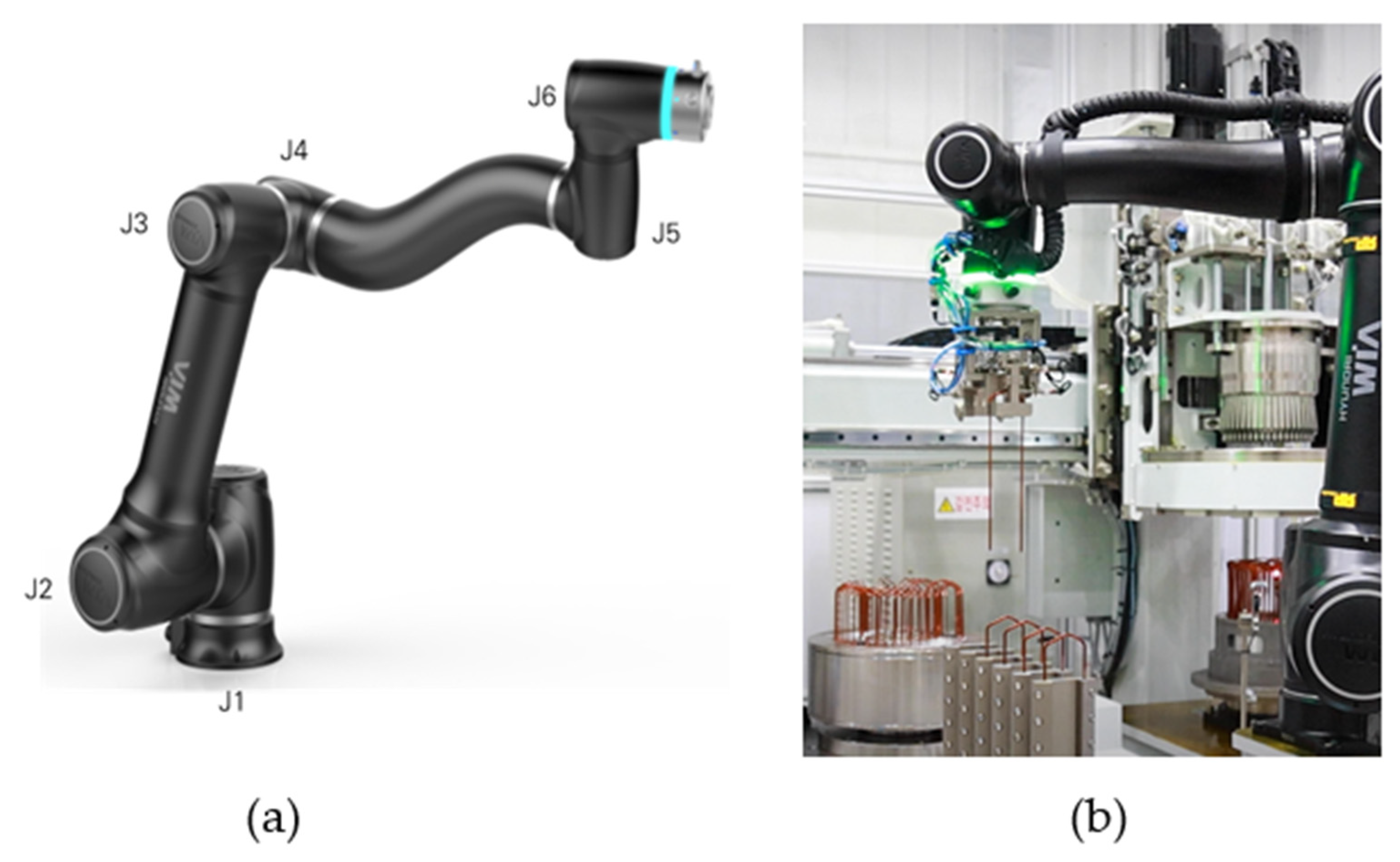
3. The 200 W Collaborative Robot Joint Motor

Figure 4a shows the robot joints of a collaborative robot being mass-produced by a company, and Figure 4b shows a collaborative robot in action. The motors for the collaborative robot joints are built in the form of one module per joint, so the wiring must be routed through the hollow shaft. Therefore, the larger the axial and radial diameters of the motor and the shorter the axial length, the more favorable the shape. This is in line with the advantages of axial flux motors, which have a high power density in a structure with a large inner and outer diameter and a short axial length. However, the size of a collaborative robot operating in the same space as a human is not much larger than a human, and the size of the motors for the robot’s joints is small. The small size of the motor makes it physically difficult to have a multipole structure with more than 20 poles.
Table 1 shows motor specifications for 200 W target collaborative robot joints. Figure 5a shows a radial-flux-type motor for a 200-W-class collaborative robot joint, which is the target motor of this paper. This motor has a 19.6 [mm] stack length with an 82 [mm] outer diameter and 44.8 [mm] inner diameter, which can be advantageous for axial flux motor applications due to its large inner and outer diameters and short stack length. Figure 5b is a double-rotor single-stator type based on the design of (a) as an axial flux motor. Figure 5c is the basic design of (a) as a single-rotor single-stator type. In this geometry, a combination of high pole and slot counts can be used to reduce the thickness of the back yoke to allow for more turns. However, for practical manufacturing considerations, combinations with more than 20 slots require very thin tooth thicknesses. This is very difficult to manufacture, so a 16-pole 18-slot combination with a high winding coefficient in the 18-slot combination was selected as the basic model. In addition, the maximum saturation of the rotor back yoke is less than 1.7 [T], so the basic design was carried out within the same size.

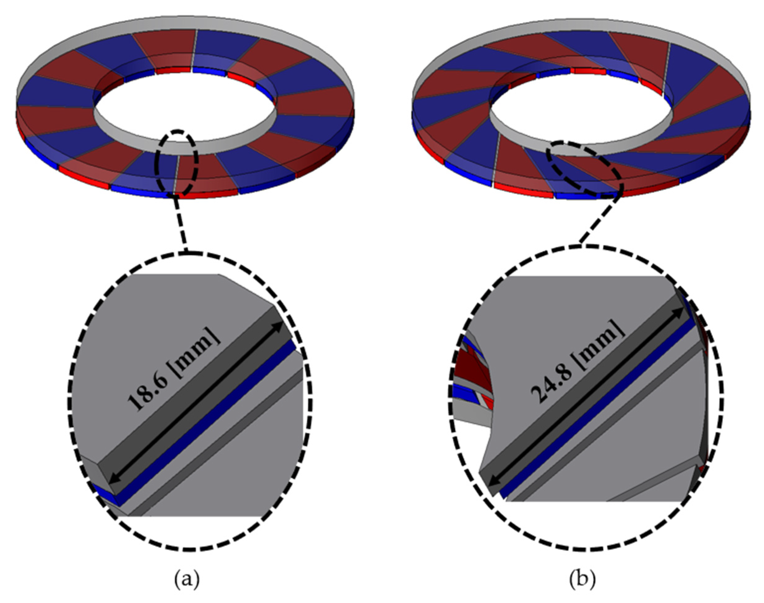
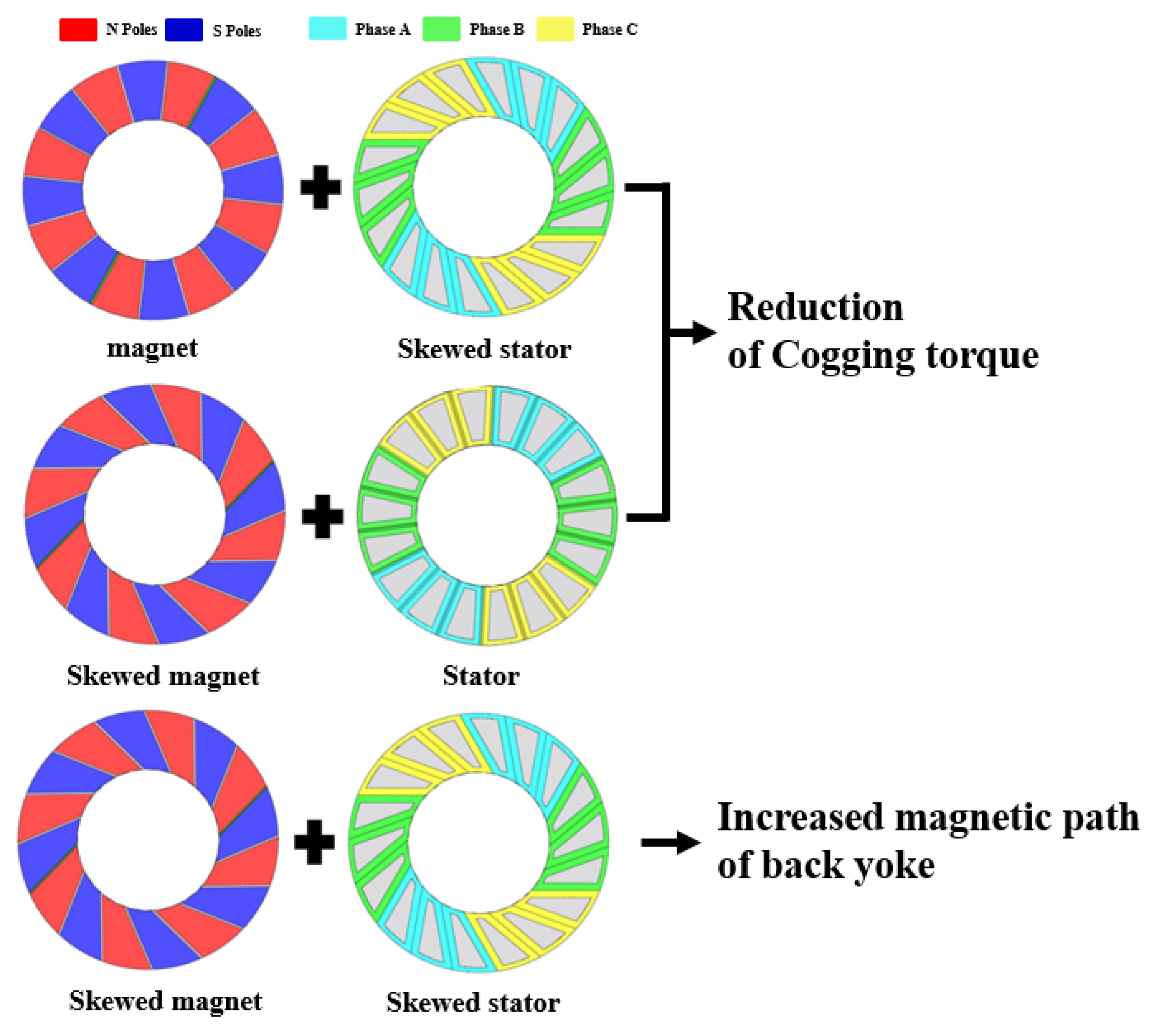
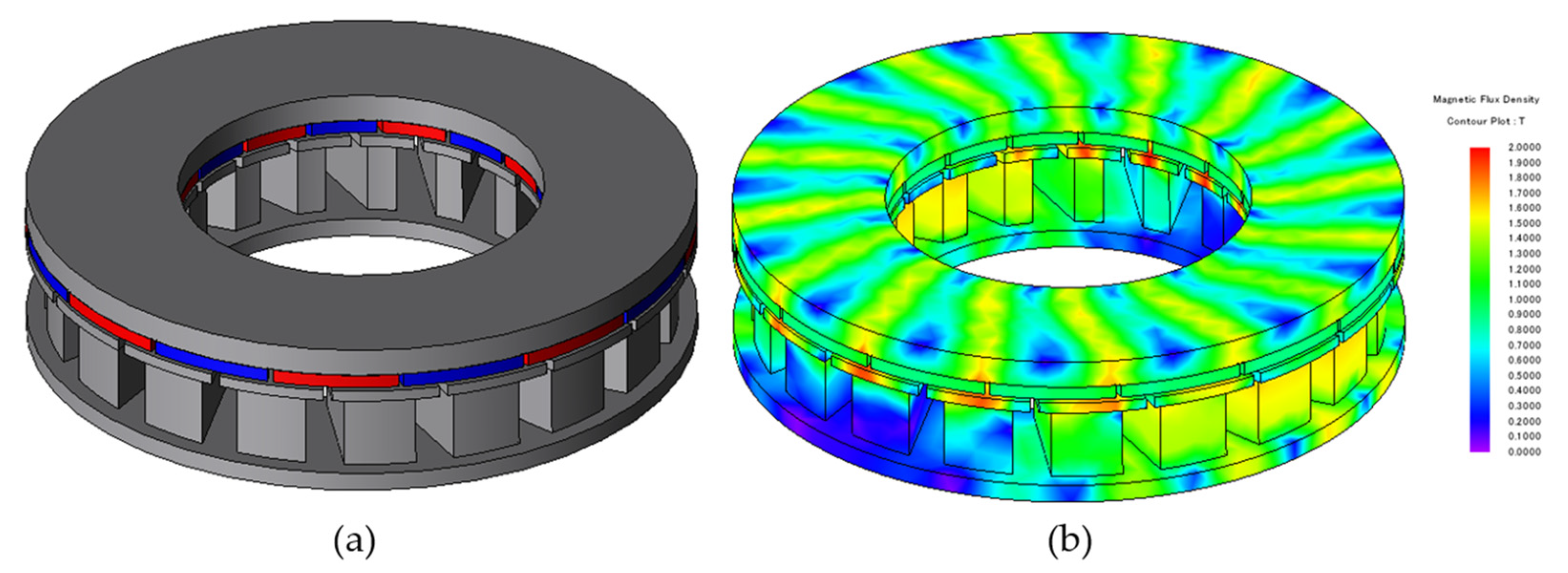
4. Same-Direction Skew

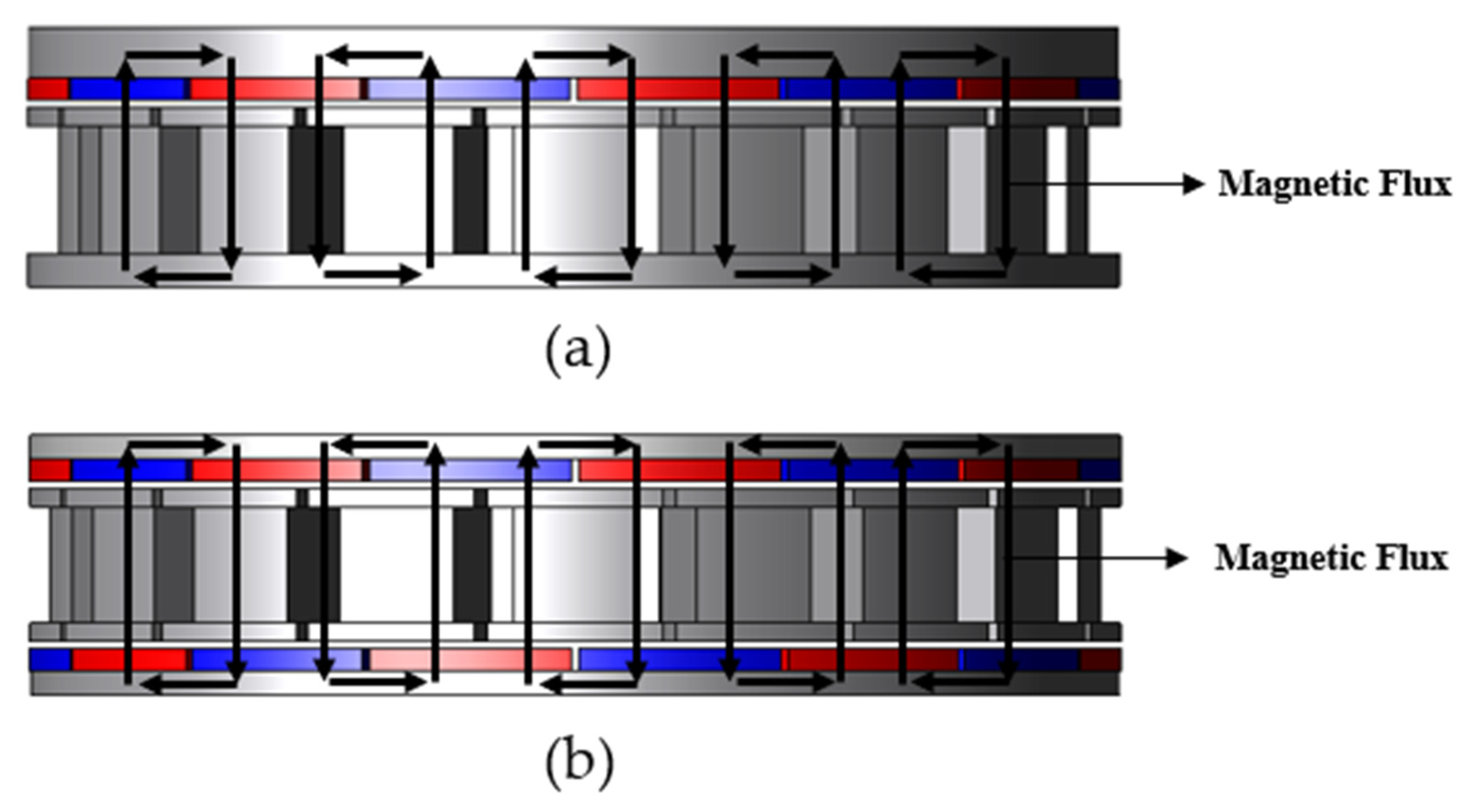
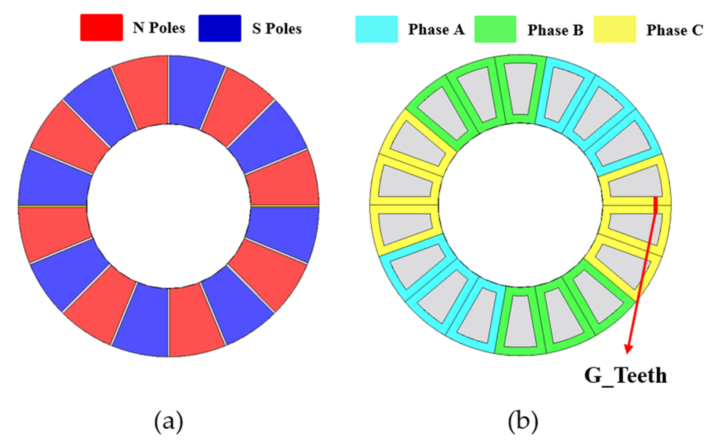
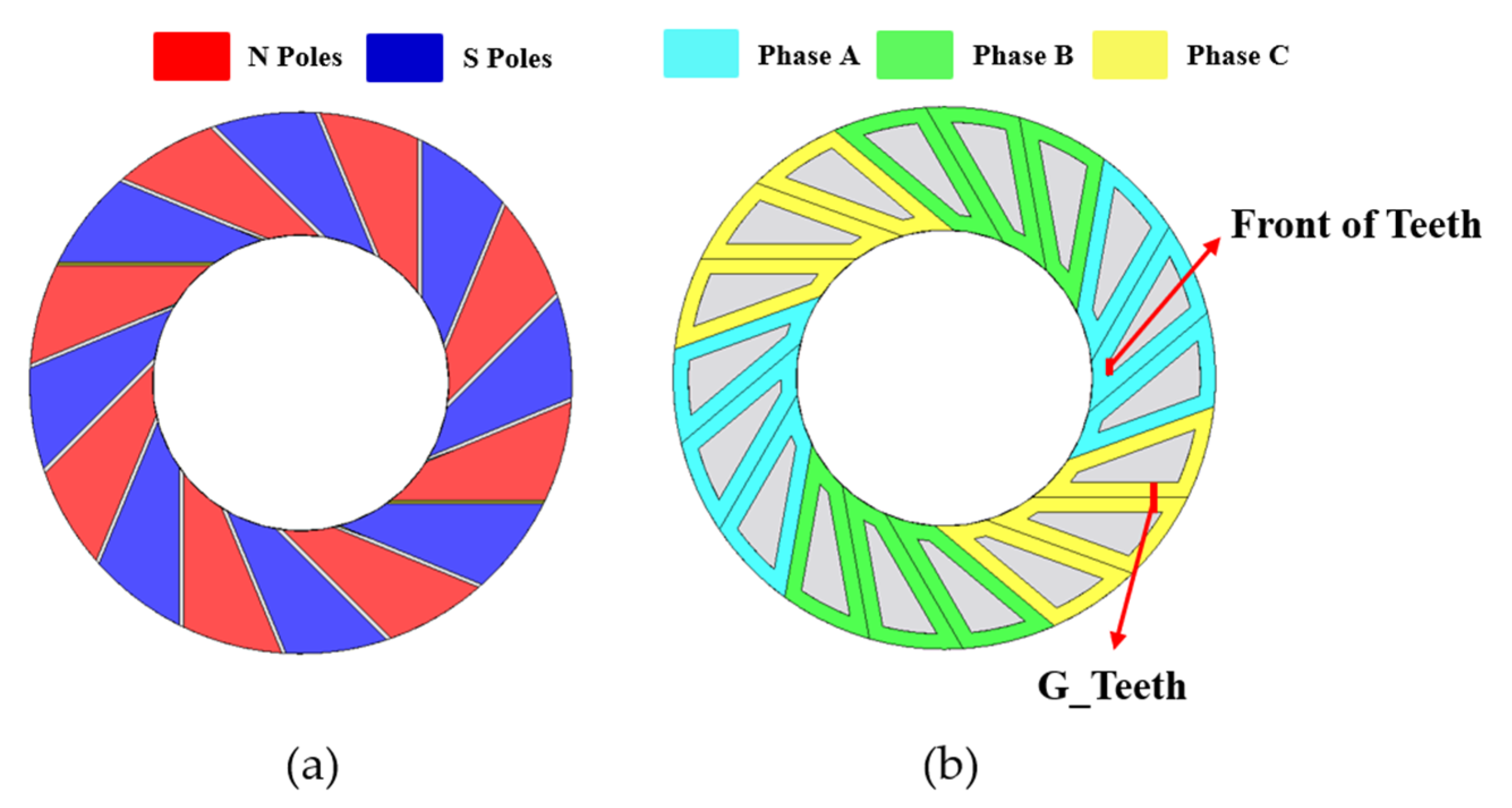
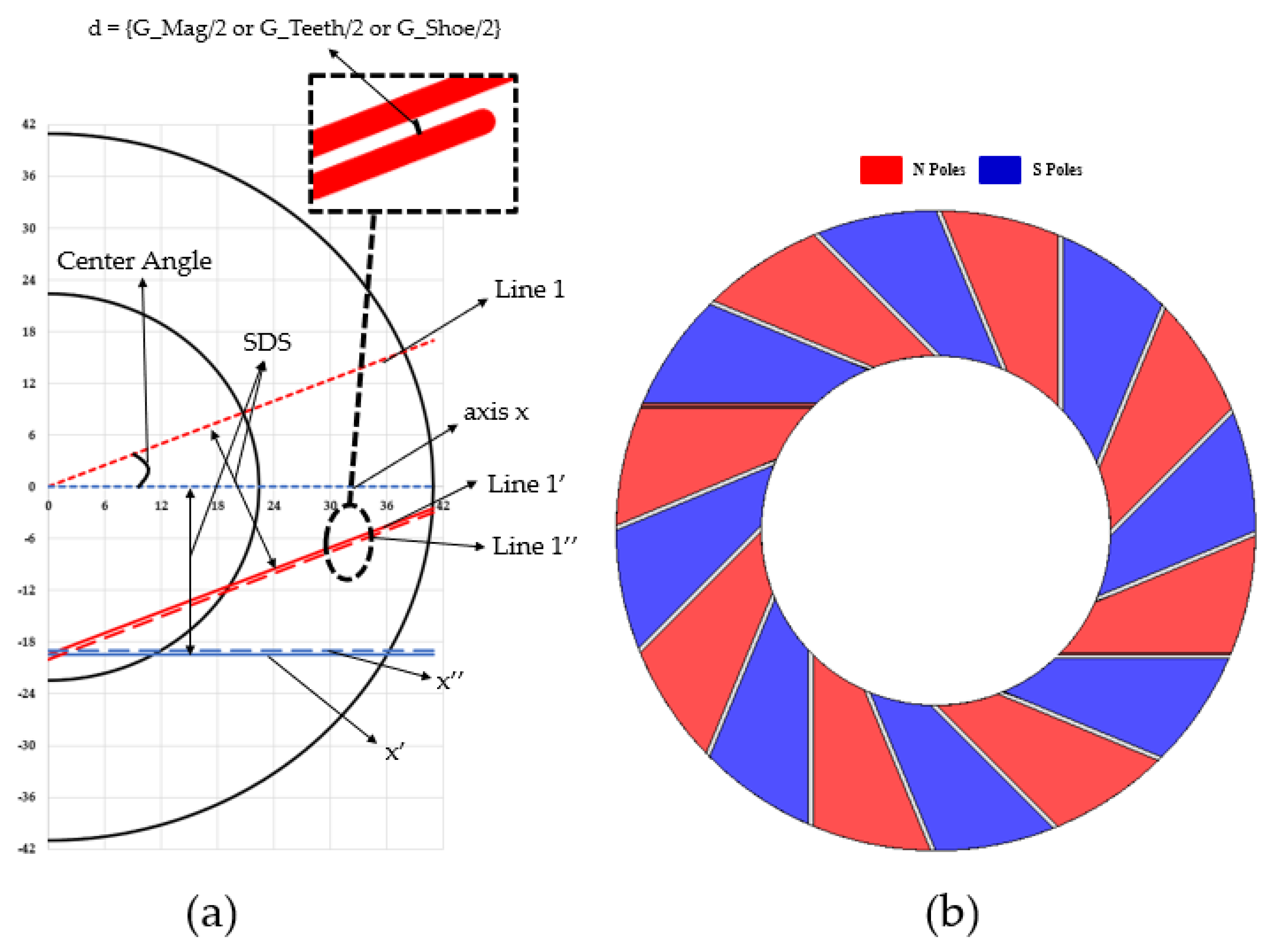
4.1. Principal of Same-Direction Skew

Applying skew to the rotor’s permanent magnets increases the cross-sectional area of the flux path through the rotor back yoke. Figure 6a shows a cross section of the rotor back yoke with the original geometry with no skew applied to the permanent magnet. Figure 6b shows the geometry and back yoke cross section with skew applied to the permanent magnet. For the same thickness of the rotor back yoke, the cross-sectional length increases from 18.6 mm to 24.8 mm as the skew is applied to the rotor’s permanent magnets. This means that the cross-sectional area of the magnetic flux passing through the rotor is increased by about 33%.
Figure 7a shows the existing geometry with no skew applied to the rotor’s permanent magnets. Figure 7b shows the stator geometry with no skew applied, indicating the winding layout and tooth spacing as G_Teeth. Figure 8a shows the geometry with skew applied to the rotor’s permanent magnets. Figure 8b shows the stator geometry with skew applied. In Figure 8b, the winding layout is shown with the tooth spacing as G_Teeth and the front of the teeth close to the inner diameter as Front of Teeth. G_Teeth also refers to the physical thickness of winding that the number of turns can be wrapped around at the tooth spacing. As the skew is applied, the area of the teeth gradually decreases, and the front part of the teeth gradually becomes thinner. When the front of the teeth is very thin, it is difficult to manufacture, vulnerable to magnetic saturation, and has difficulty withstanding winding tension. In this paper, the minimum thickness of the front end of the teeth was selected to be more than 3 [mm]. In addition, to minimize performance degradation due to the reduction in tooth area with the increase in SDS, a shoe-shaped structure was adopted.
The purpose of the skew of the axial flux motor being studied is to reduce cogging torque and torque ripple. Typically, it is a shape in which skew is applied to the rotor’s permanent magnet as shown in Figure 7a or a shape applied to the stator as shown in Figure 8b. In both cases, it is a shape that mitigates the magnetic resistance difference according to the rotation of the rotor. However, with that shape, cogging torque and torque ripple are reduced, but the amount of flux linkage is reduced compared to the non-skew model. As shown in Figure 8, when the skew is applied to the teeth and shoes in the same size and direction as the permanent magnet of the rotor, there is no reduction in cogging torque and no reduction in flux linkage. Furthermore, skew in the same direction has the effect of increasing the magnetic path of the rotor and stator back yoke. For an intuitive comparison, the performance difference according to skew is shown in Figure 9.

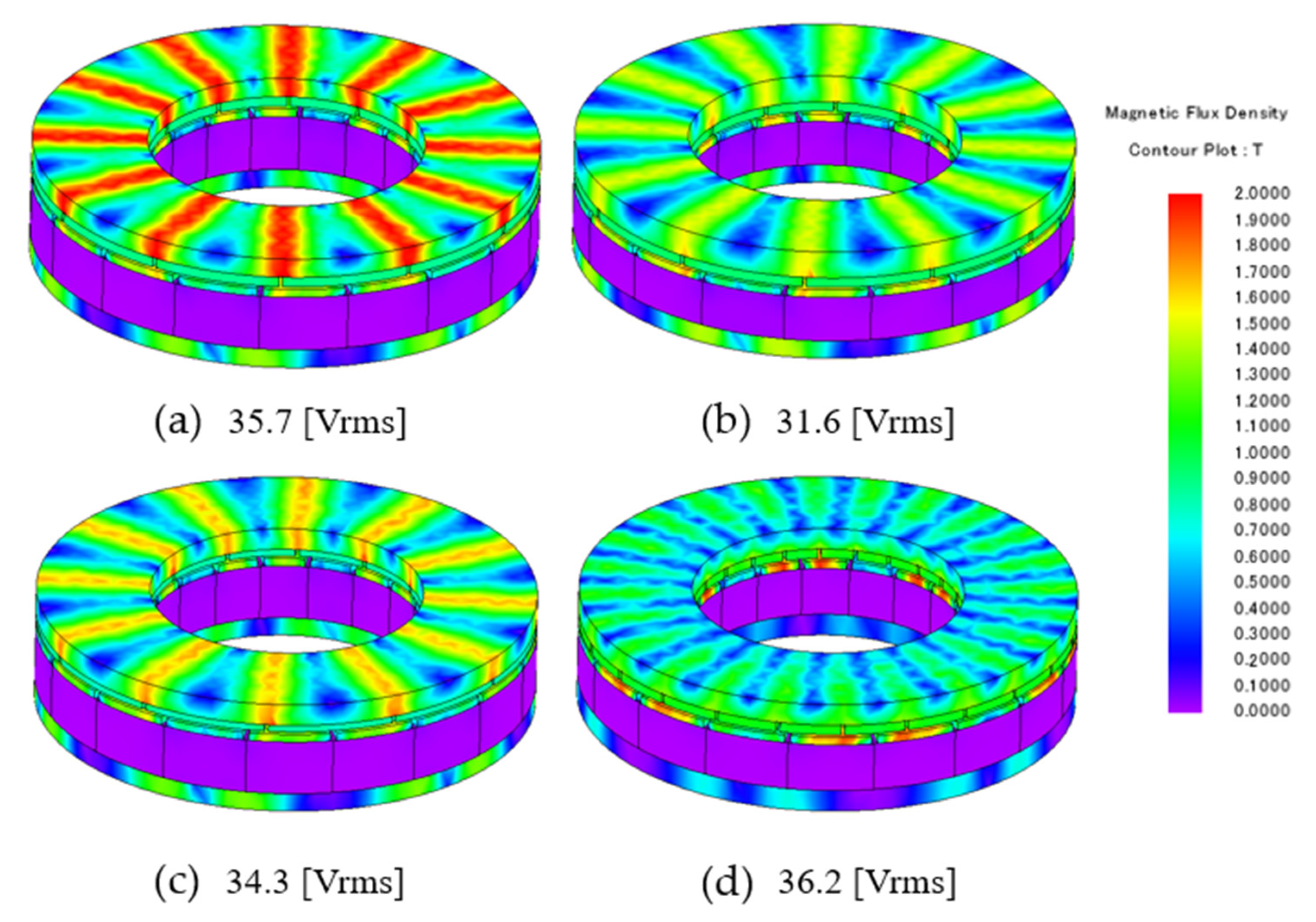
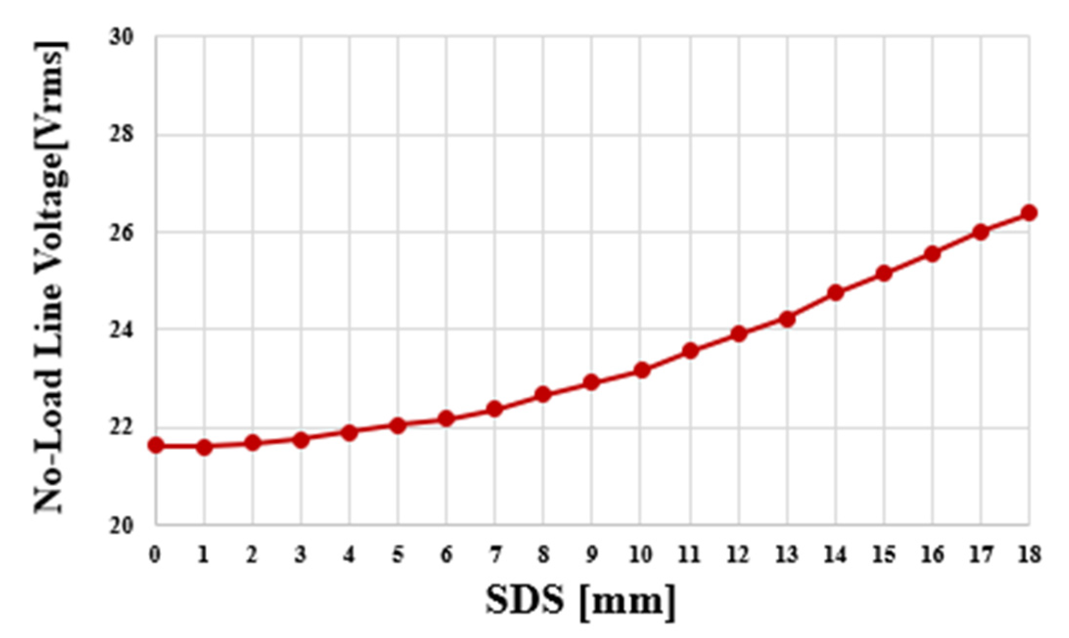
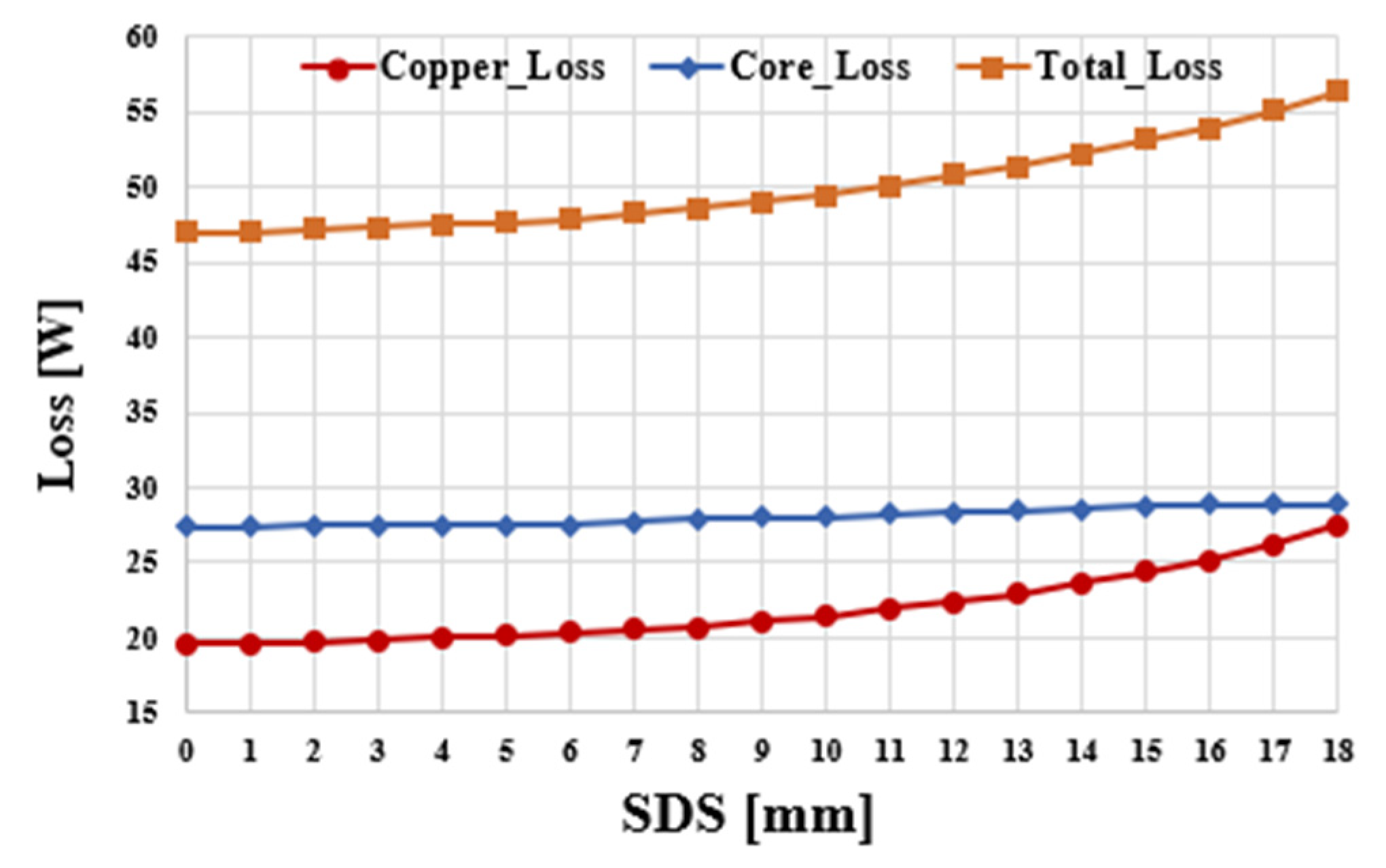
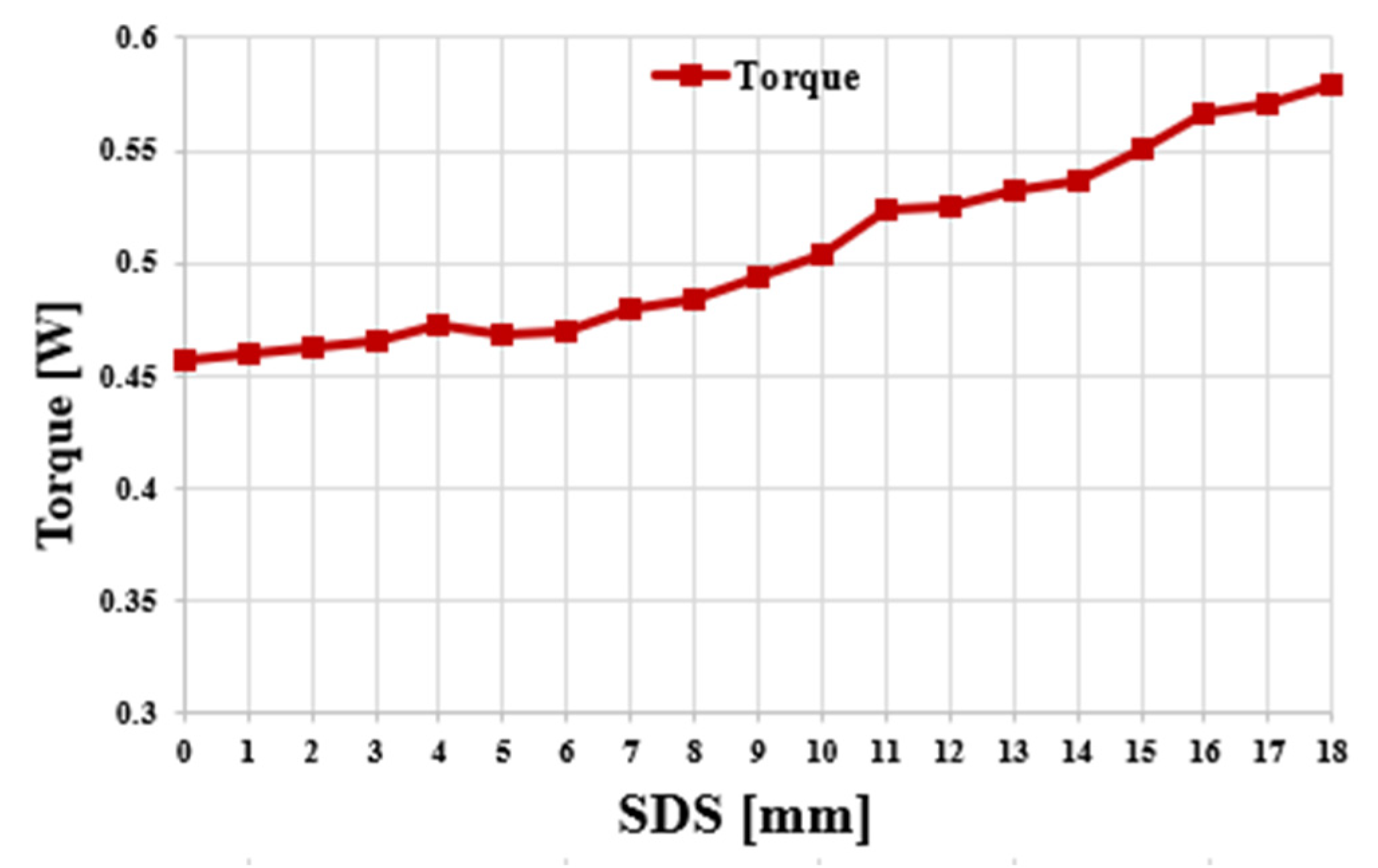
4.2. Numerical Approach to Same-Direction Skew

Figure 10a shows how to apply skew to teeth, shoes, and permanent magnets. In (b), we can see the permanent magnet’s shape made using the method in (a). Center Angle represents the mechanical angle occupied by one tooth or shoe or one permanent magnet in a counterclockwise direction based on the x-axis. In the case of 16 poles and 18 slots, the angle occupied by one tooth or shoe is 20 degrees, and, in the case of the permanent magnets, it is 22.5 degrees. For the convenience of explanation, it is described based on the permanent magnet. Since the angle occupied by one permanent magnet from the x-axis passes through the origin at 22.5 degrees and has a tan of (22.5 degrees) as the slope, a = tan (360 deg/N_Poles). Therefore, Line1 can be defined by Equation (3). To create a skew applied shape, a new straight line Line1′ with a distance as much as the red arrow is defined as Equation (4) based on Line1. As b = −SDS/cos(360 deg/N_poles), the size of the separation distance is expressed as SDS, and it represents a distance variable as an abbreviation of same-direction skew. In addition, a straight line separated by SDS from the x-axis in the y-axis direction is defined as x′ by Equation (5). To prevent leakage between permanent magnets, a straight line with a distance of G_Mag/2 below the Line1′ standard is defined as line1″ by Equation (6) to apply the separation distance. c = −(SDS + d)/cos (360 deg/N_poles), where d is G_Mag/2 for the permanent magnets and G_Teeth/2, G_Shoe/2 for the shoes. A straight line with a distance of G_Mag/2 in the upward direction based on x′ is defined as x″ by Equation (7). The shape of the permanent magnet with the skew applied is determined at the intersection of the inner and outer diameter of the rotor back yoke and line1″ and x″. In the case of the teeth, their shape can be determined by having an angle of 360/N_Slots in the counterclockwise direction based on the x-axis and applying G_Mag/2 as L_Slots/2, which is half of the interval between slots. In the case of the shoes, their shape can be determined by defining G_Mag/2 as G_Shoe/2, the distance between the shoes, at the same angle as the teeth.
y = a x
y = a x + b
y = b
y = a x + c
y = c
x 2 + y 2 = R _ I n n e r 2
x 2 + y 2 = R _ O u t e r 2
( a 2 + 1 ) x 2 2 a b x + b 2 R _ I n n e r 2 = 0
X 1 = 2 a b ( 2 a b ) 2 4 ( a 2 + 1 ) ( b 2 R _ I n n e r 2 ) 2 ( a 2 + 1 ) ,   Y 1 = a X + b
( a 2 + 1 ) x 2 2 a b x + b 2 R _ O u t e r 2 = 0
X 2 = 2 a b ( 2 a b ) 2 4 ( a 2 + 1 ) ( b 2 R _ O u t e r 2 ) 2 ( a 2 + 1 ) ,   Y 2 = a X + b
( X 2 X 1 ) 2 + ( Y 2 Y 1 ) 2 = Length 1
x 2 = R _ I n n e r 2 b 2
X 3 = ( R _ I n n e r 2 b 2 ) 2 ,   Y 3 = b
x 2 = R _ O u t e r 2 b 2
X 4 = ( R _ O u t e r 2 b 2 ) 2 ,   Y 4 = b
( X 4 X 3 ) 2 + ( Y 4 Y 3 ) 2 = Length 2
In the rotor back yoke, the area between the permanent magnets is the part where the magnetic flux is concentrated, and it is the part that is vulnerable to magnetic saturation even within the back yoke. The sectional area of the rotor back yoke between the existing permanent magnets was the same, but the cross-sectional area of the two back yokes is different depending on the application of the same-direction skew. The cross-sectional area of a given part can be obtained using the formula. The cross-sectional area can be obtained by multiplying the length of the cross section by the thickness of the rotor back yoke. The line connecting Line1′ and the intersection of the equation of the circle of the inner diameter of the rotor and the intersection of the equation of the circle of the outer diameter is the first section of the rotor back yoke between the permanent magnets. Equation (10) represents a simultaneous equation consisting of Equations (4) and (8). After solving Equation (10), the intersection of the inner diameter circular equation and Line 1′ comes out, which can be summarized as Equation (11). Equation (12) represents a simultaneous equation consisting of Equations (4) and (9). If you solve Equation (12), the intersection of the outer diameter circle equation and Line1′ will come out, which can be summarized by Equation (13). If the lengths of the two intersections are known, the length of the cross section of the rotor back yoke can be found, and the cross section area of the back yoke of the rotor can be obtained by multiplying the thickness of the back yoke. Equation (14) represents the length of Section 1 according to the skew. The line connecting the intersection between x′ and the equation of the circle of the inner diameter of the rotor and the intersection of the equation of the circle of the outer diameter is the second section of the rotor back yoke between the permanent magnets. Equation (15) represents a simultaneous equation consisting of Equations (5) and (10). After solving Equation (15), the intersection of the inner diameter circle equation and x′ comes out, which can be summarized as Equation (16). Equation (17) represents a simultaneous equation consisting of Equations (5) and (9). After solving Equation (17), the intersection of the outer diameter circle equation and Line 1′ comes out, which can be summarized as Equation (18). In the same way as above, the length of the cross section of the rotor back yoke can be summarized by Equation (19) and represents the length of Cross Section 2 according to the skew. Since the thickness of the back yoke is 2.7 mm, the table below shows the same back yoke cross-sectional area condition and back yoke length according to the SDS parameters. In the case of a single type, the stator back yoke is less prone to magnetic saturation than the rotor back yoke. Therefore, the ratio of stator back yoke to rotor back yoke was 1:1.5. The length of the cross section of the existing rotor back yoke is 18.6 mm because it is the distance from the inner diameter of the rotor back yoke to the outer diameter, and the cross-sectional area is 81.78 mm2. When applying the same-direction skew, the path of magnetic flux can be increased without increasing the thickness of the rotor back yoke. According to the same-direction skew application, the length of the cross section of the back yoke becomes a line connecting the points where the inner and outer diameters of the rotor back yoke meet Line1′, and a line connecting the points where the inner and outer diameters of the rotor back yoke meet x′. The length of the line segment is the intersection of the inner diameter circular equation of the rotor back yoke represented by Equation (8) and line1, and the distance between the intersection of line1 and the outer diameter circular equation of the rotor back yoke represented by Equation (9). Based on the average lengths of the two straight lines, the thickness of the back yoke was reduced by the amount the cross-sectional area was increased by the application of the same-direction skew to make it the same as the cross-sectional area of the existing rotor back yoke. Tooth length was also increased. The contents are presented in Table 2.

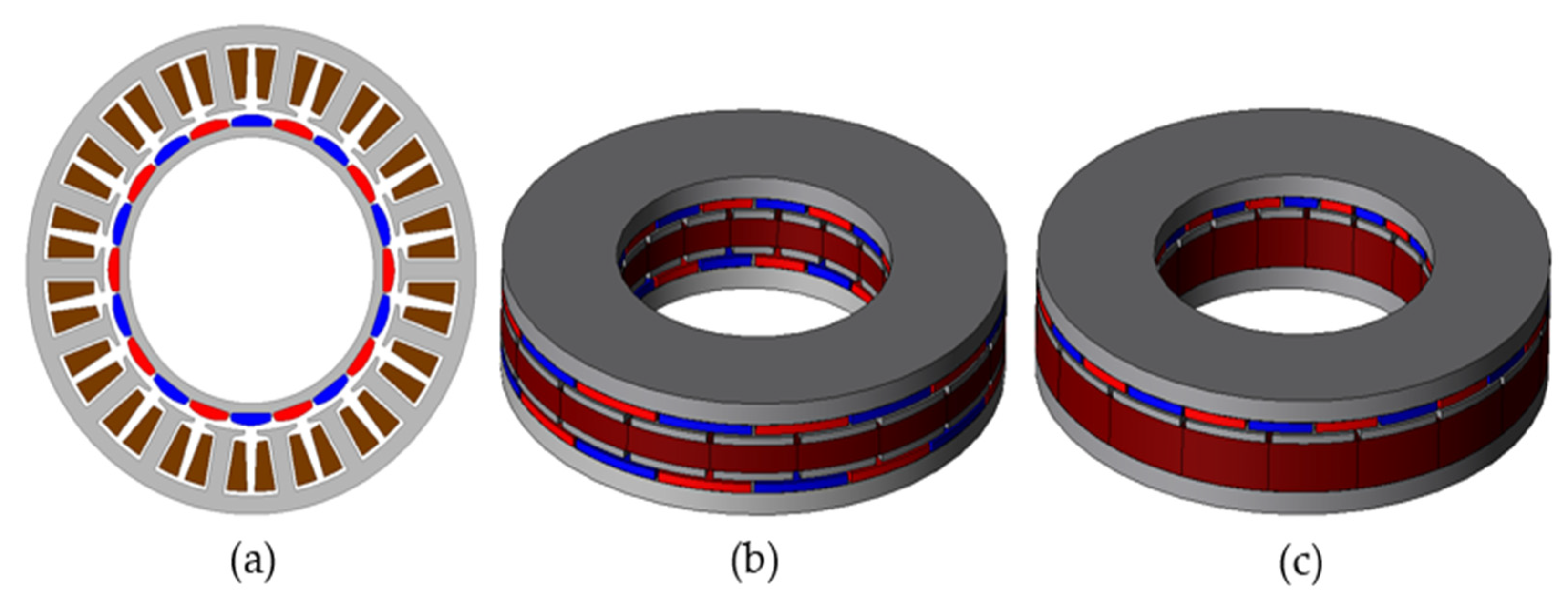
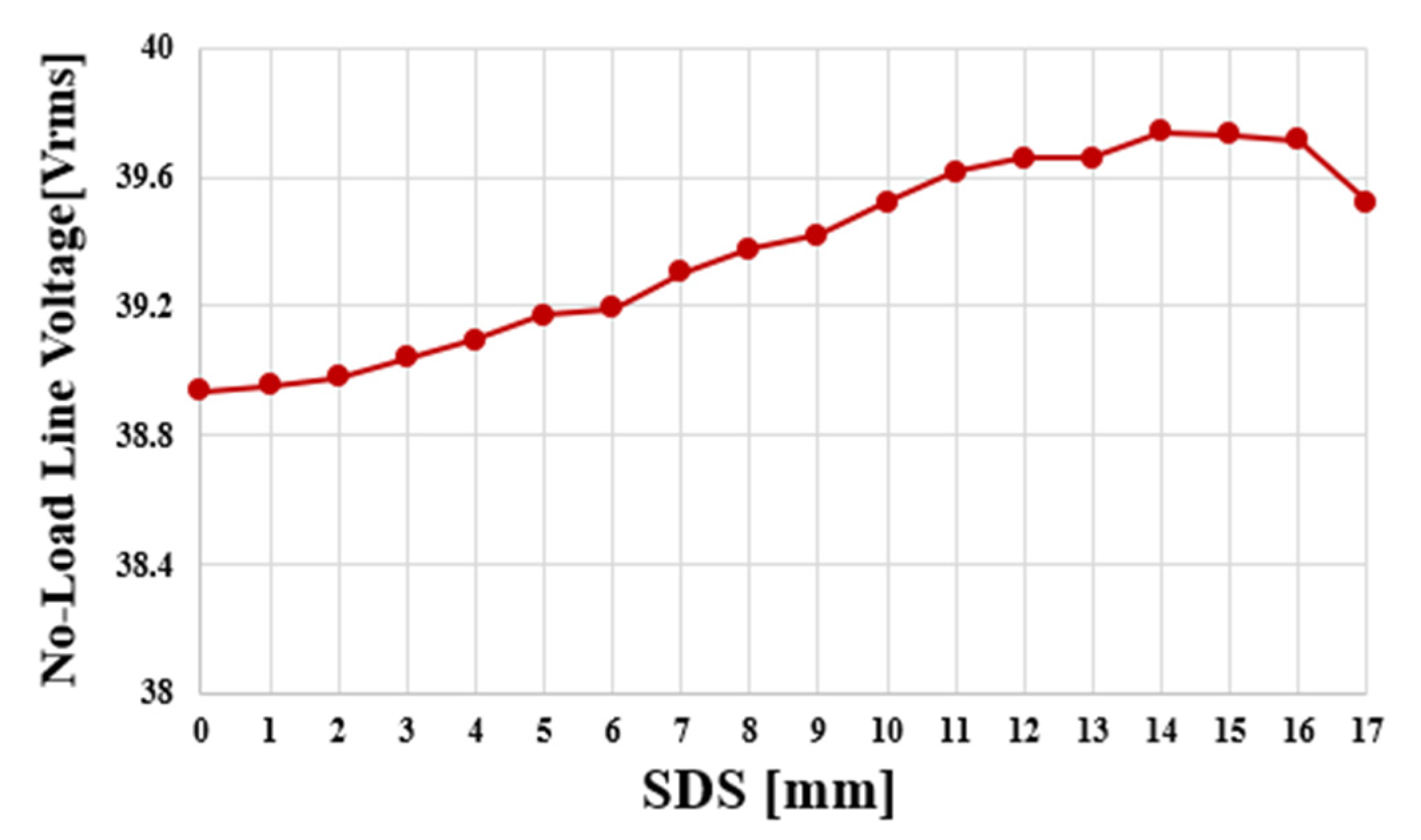
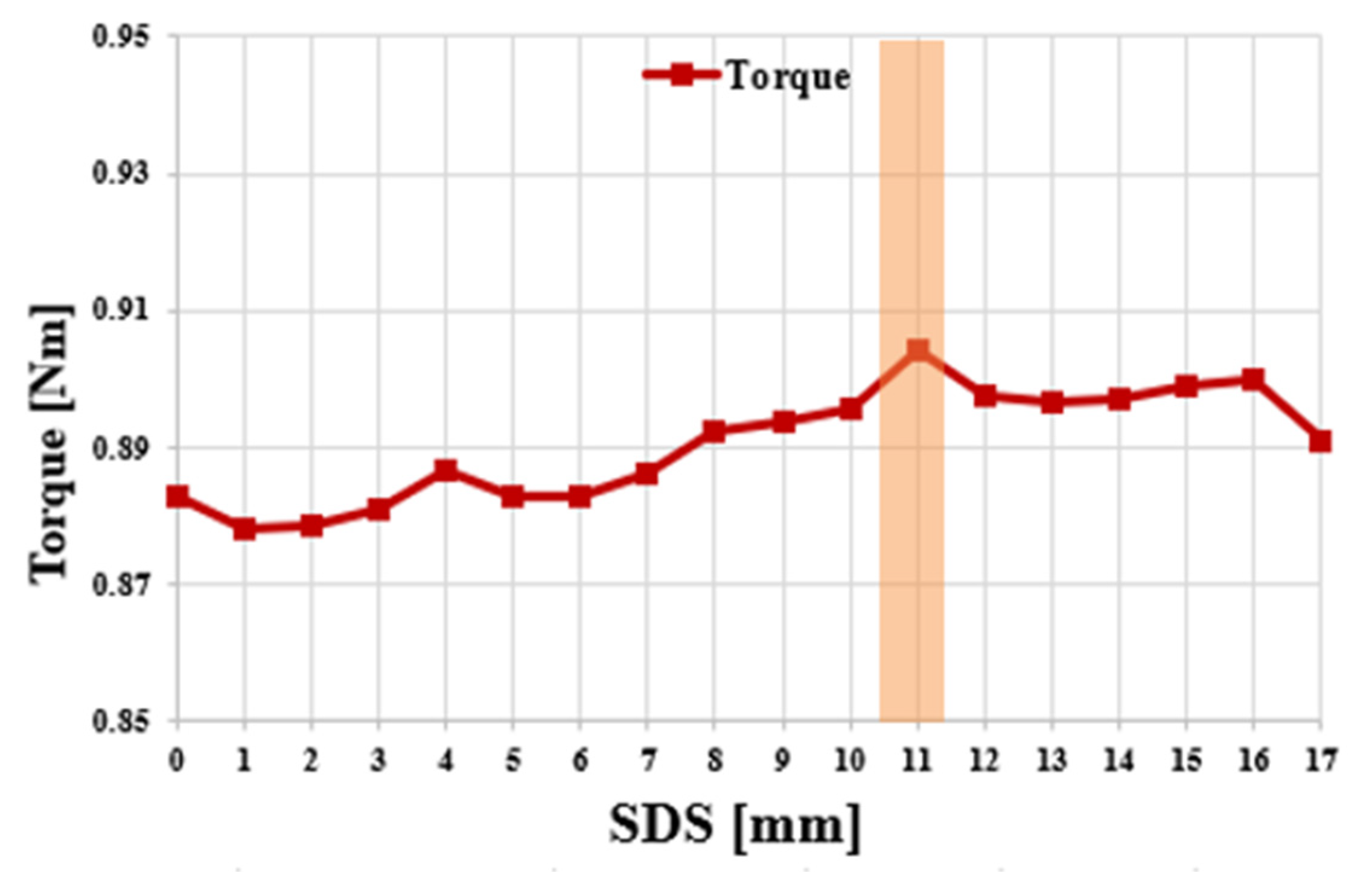
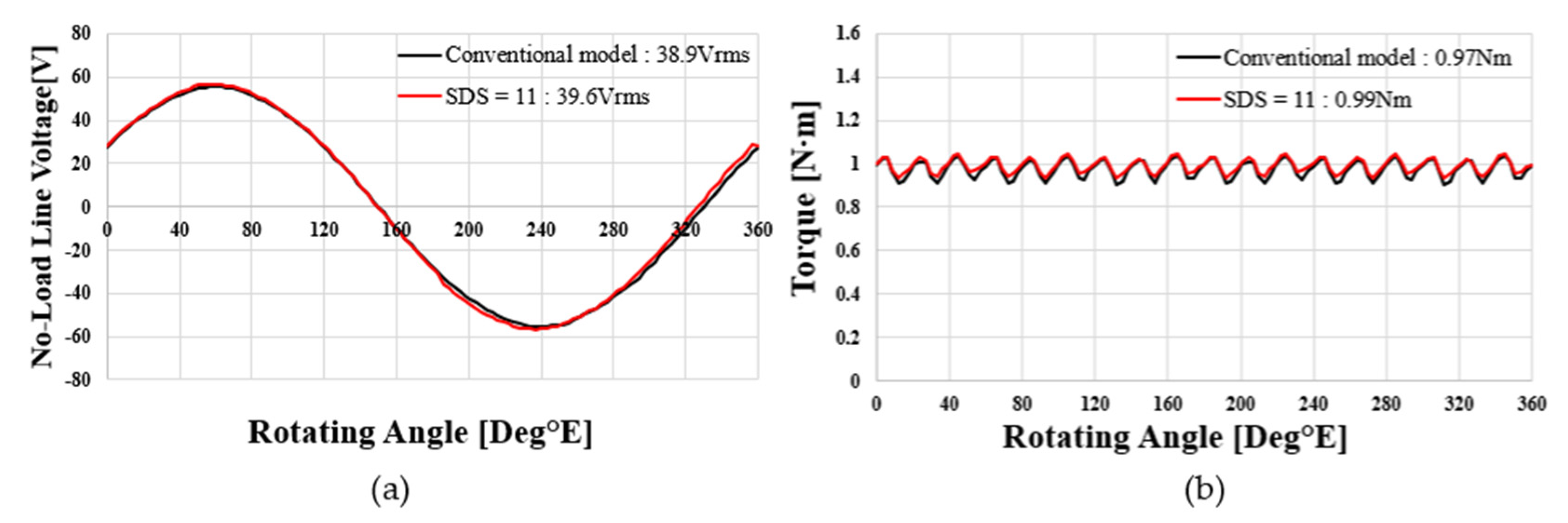
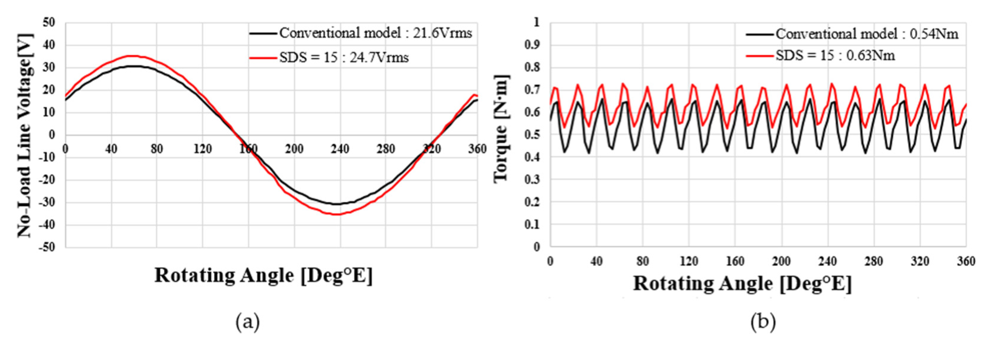
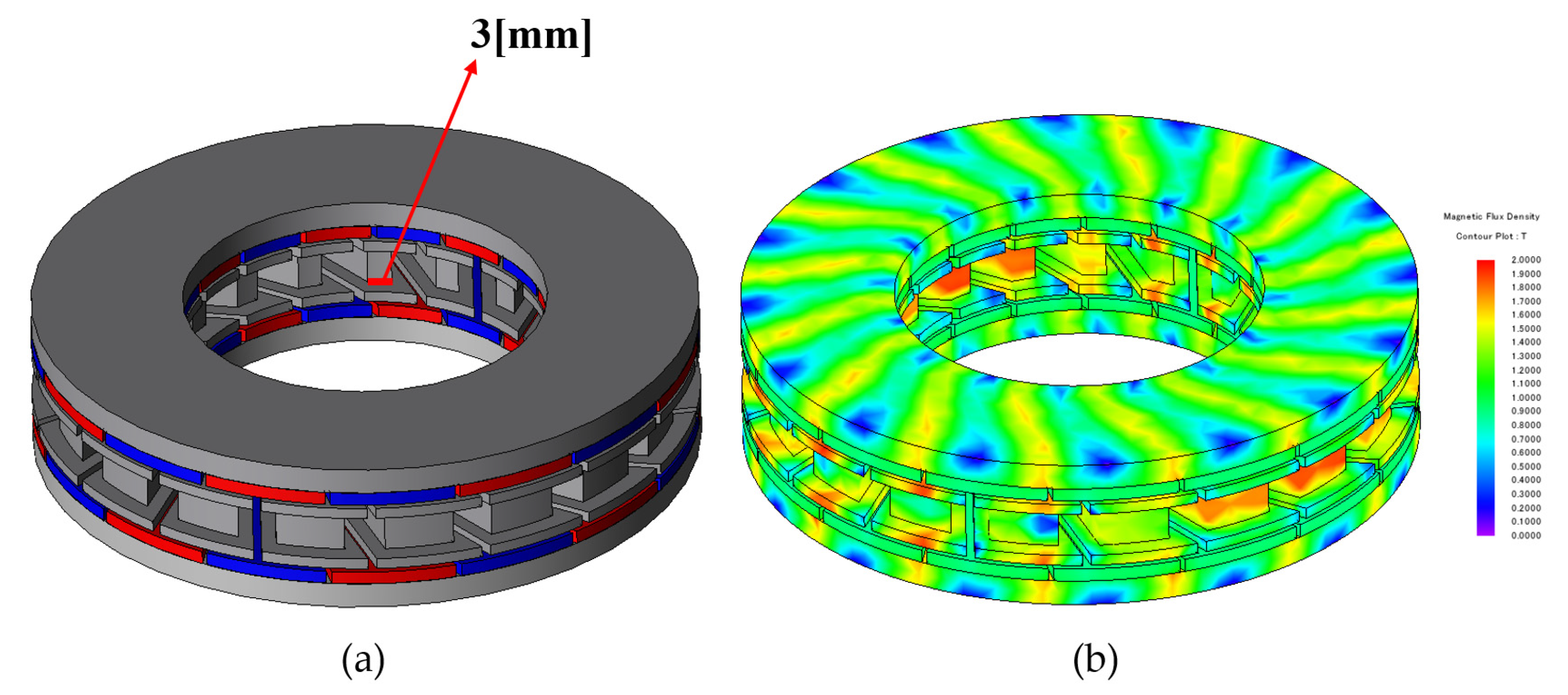
4.3. Same-Direction Skew Effect by Rotor Type

Figure 11 shows the no-load line voltage according to the increase in SDS in the single-rotor single-stator type. According to the increase in SDS, the line voltage at no load shows an increasing trend up to SDS = 14, but, from 15, it shows a decreasing trend. This is due to the increase in the number of turns according to the increase in tooth length up to SDS = 14, so the voltage increases. However, as the SDS increases, the effect of the reduction in flux linkage due to the decrease in tooth area seems to be greater than the increase in tooth length. Since the ratio of the thickness of the stator back yoke and the rotor back yoke is 1:1.5, the reduction in thickness of the stator back yoke is less than that of the rotor back yoke according to the same-direction skew. Figure 12 shows copper loss, iron loss, and total loss according to the increase in SDS in the single-rotor single-stator type. As the SDS increases, copper loss increases because the side surface of the teeth has an elongated shape. Iron loss increases and then decreases again. Since copper loss is more dominant than iron loss and the increase is large, the total loss increases. Figure 13 shows shaft torque under load according to the increase in SDS in a single, shoe-type structure. In Figure 11, as SDS increases, the line-to-line voltage at no load shows a tendency to increase up to SDS = 14. The reason why shaft torque under load has a maximum value of SDS = 11 and not SDS = 14 is the effect of loss due to copper loss that shows a steady increasing trend. Figure 14 shows the performance comparison between the conventional model and the model selected with SDS = 11 in the single-rotor single-stator type. Figure 14a shows the line voltage comparison at no load. The conventional model has Vrms = 38.9 V and a THD of 0.6%. The SDS = 11 model increased 1.8% to 39.6 V, and THD increased to 2.3%, but 5% or less was considered acceptable. Figure 14b shows the air gap torque comparison under load. Air gap torque increased by 2% from 0.97 Nm to 0.99 Nm. Torque ripple decreased by 11.2% and 2.4% P compared to the previous 13.6%. Figure 15a shows the final shape of the single-rotor single-stator type (SDS = 11). Compared to the conventional model, line voltage at no load increased by 1.7%. Copper loss increased by 5.8%, iron loss increased by 4.8%, and total loss increased by 5.3%. In addition, shaft torque under load increased by 2.4% compared to the conventional model, which means that the power density also increased by 2.4%. Figure 14b shows the magnetic flux density under load. The maximum saturation of the back yoke did not exceed 1.7 T.
Figure 16 shows the no-load line voltage according to the increase in SDS in the double-rotor single-stator type. The double-rotor single-stator type has a double-air-gap structure and has a relatively low output compared to the single-rotor single-stator type in small sizes such as co-robot motors. According to the increase in SDS, the line-to-line voltage at no load continues to increase until SDS = 18. In the case of the double-rotor single-stator type, the effect of increasing the tooth length according to the increase in SDS is greater because the thickness of the back yoke of the rotor on both sides is reduced at the same rate. The effect of the reduction in flux linkage due to the decrease in tooth area as the SDS increased, which was observed in the single-rotor single-stator type, was not observed until SDS = 18. Figure 17 shows the copper loss, iron loss and total loss according to the increase in SDS in the double-rotor single-stator type. As the SDS increases, the sides of the teeth become longer. Since the effect of increasing the tooth length is greater than that of the single-rotor single-stator type, the range of increase in copper loss is also greater. The iron loss shows an increasing aspect as the SDS increases. In the doble rotor single stator type, copper loss is more dominant than iron loss and the increase is large, so the total loss increases more steeply than the single-rotor single-stator type. Figure 18 shows the shaft torque under load according to the increase in SDS of the double-rotor single-stator type. In Figure 16, the line-to-line voltage at no load showed a steady increase according to the increase in SDS. The shaft torque under load also shows a steady increase. This is because the effect of increasing the performance due to the increase in tooth length is higher than the effect of copper loss. As same-direction skew is applied, Front of Teeth gradually decreases. To increase the possibility of actual production, the minimum thickness of the front of teeth of the final model was selected as 3 mm. The skew variable of the final model is SDS = 15. Figure 19 shows the performance comparison between the conventional model and the model selected with SDS = 15 in Double-rotor single-stator type. Figure 19a shows the line voltage comparison at no load. The conventional model has Vrms = 21.6 Vrms and THD is 0.57%. SDS = 15 model increased by 14.4% to 24.7 Vrms, and THD increased to 2.4%, but it was judged to be acceptable below 5%. Figure 19b shows the air gap torque comparison under load. The air gap torque increased by 16.7% from 0.54 Nm to 0.63 Nm. Torque ripple decreased by 13.3% P from 44.9% to 31.6%. Compared to the conventional model, the final model increased the line voltage at no load by 16.2%. Copper loss increased by 24.4%, iron loss increased by 5.1%, and total loss increased by 13%. In addition, the shaft torque under load increased by 20% compared to the previous one, which means that the power density also increased by 20%. Figure 20a shows the final shape of double-rotor single-stator type (SDS = 15). Figure 20b shows the magnetic flux density under load. The maximum saturation of the back yoke did not exceed 1.7 [T].

5. Conclusions

In this paper, a study was conducted on the power density improvement of axial flux motors according to same-direction skew. The disadvantages of the conventional magnetic saturation relaxation method are presented, and it is shown that they can be overcome through same-direction skew. The characteristics and specifications of the target motor were presented, and it was shown that there could be advantages in the axial flux motor structure. In addition, the principle of same-direction skew was explained, and it was solved mathematically. Since the length of the cross section of magnetic flux increases according to the application of the same-direction skew, the cross section of the back yoke magnetic flux path is fixed and the thickness is reduced to increase performance. A shape that is relatively easy to manufacture was implemented by analyzing the performance deterioration factors caused by the application of same-direction skew. In addition, by analyzing the performance increase factors and deterioration factors according to same-direction skew, the effective types of each topology were compared and analyzed.

Author Contributions

Conceptualization, W.-H.K.; methodology, M.-K.H.; software, S.-W.S.; validation, M.-K.H.; formal analysis, H.-J.P.; investigation, H.-J.P.; resources, M.-K.H.; data curation, M.-K.H.; writing—original draft preparation, M.-K.H.; writing—review and editing, H.-J.P. and D.-H.J.; visualization, M.-K.H. and D.-H.J.; supervision, W.-H.K. All authors have read and agreed to the published version of the manuscript.

Funding

This research was supported by a grant from the Basic Research Program funded by the Korea Institute of Machinery and Materials (grant number: NK242J) and, in part, by the Gachon University research fund of 2020 (GCU-202002990001).

Data Availability Statement

Not applicable.

Conflicts of Interest

The authors declare no conflict of interest.

References

  1. Jing, L.; Tang, W.; Wang, T.; Ben, T.; Qu, R. Performance Analysis of Magnetically Geared Permanent Magnet Brushless Motor for Hybrid Electric Vehicles. IEEE Trans. Transp. Electrif. 2022, 8, 2874–2883. [Google Scholar] [CrossRef]
  2. Fang, L.; Li, D.; Qu, R. Torque Improvement of Vernier Permanent Magnet Machine with Larger Rotor Pole Pairs than Stator Teeth Number. IEEE Trans. Ind. Electron. 2023. [Google Scholar] [CrossRef]
  3. Jing, L.; Liu, W.; Tang, W.; Qu, R. Design and Optimization of Coaxial Magnetic Gear with Double-Layer PMs and Spoke Structure for Tidal Power Generation. IEEE/ASME Trans. Mechatron. 2023. [Google Scholar] [CrossRef]
  4. Nishanth, F.; Van Verdeghem, J.; Severson, E.L. A Review of Axial Flux Permanent Magnet Machine Technology. IEEE Trans. Ind. Appl. 2023. [Google Scholar] [CrossRef]
  5. Cavagnino, A.; Lazzari, M.; Profumo, F.; Tenconi, A. A comparison between the axial flux and the radial flux structures for PM synchronous motors. In Proceedings of the Conference Record of the 2001 IEEE Industry Applications Conference: 36th IAS Annual Meeting (Cat. No.01CH37248), Chicago, IL, USA, 30 September–4 October 2001; Volume 3, pp. 1611–1618. [Google Scholar] [CrossRef]
  6. Bruzinga, G.R.; Filho, A.J.S.; Pelizari, A. Analysis and Design of 3 kW Axial Flux Permanent Magnet Synchronous Motor for Electric Car. IEEE Lat. Am. Trans. 2022, 20, 855–863. [Google Scholar] [CrossRef]
  7. Ferreira, Â.P.; Costa, A.F. Electromagnetic finite element design of axial flux permanent magnet machines for low speed applications. In Proceedings of the 2014 International Conference on Electrical Machines (ICEM), Berlin, Germany, 2–5 September 2014; pp. 1139–1145. [Google Scholar] [CrossRef]
  8. Neethu, S.; Nikam, S.P.; Wankhede, A.K.; Pal, S.; Fernandes, B.G. High speed coreless axial flux permanent magnet motor with printed circuit board winding. In Proceedings of the 2017 IEEE Industry Applications Society Annual Meeting, Cincinnati, OH, USA; 2017; pp. 1–6. [Google Scholar] [CrossRef]
  9. Neethu, S.; Nikam, S.P.; Pal, S.; Wankhede, A.K.; Fernandes, B.G. Performance Comparison Between PCB-Stator and Laminated-Core-Stator-Based Designs of Axial Flux Permanent Magnet Motors for High-Speed Low-Power Applications. IEEE Trans. Ind. Electron. 2020, 67, 5269–5277. [Google Scholar] [CrossRef]
  10. Chen, Y.; Pillay, P.; Khan, A. PM wind generator topologies. IEEE Trans. Ind. Appl. 2005, 41, 1619–1626. [Google Scholar] [CrossRef]
  11. Colton, J.; Patterson, D.; Hudgins, J. Design of a low-cost and efficient integrated starter-alternator. In Proceedings of the 2008 4th IET Conference on Power Electronics, Machines and Drives, York, UK, 2–4 April 2008; pp. 357–361. [Google Scholar] [CrossRef]
  12. Liu, L.; Guo, F.; Zou, Z.; Duffy, V.G. Application, development and future opportunities of collaborative robots (cobots) in manufacturing: A literature review. Int. J. Hum. Comput. Interact. 2022, 1–18. [Google Scholar] [CrossRef]
  13. Wu, S.-H.; Hong, X.-S. Integrating Computer Vision and Natural Language Instruction for Collaborative Robot Human-Robot Interaction. In Proceedings of the 2020 International Automatic Control Conference (CACS), Hsinchu, Taiwan, 4–7 November 2020; pp. 1–5. [Google Scholar] [CrossRef]
  14. Hentout, A.; Aouache, M.; Maoudj, A.; Akli, I. Human–robot interaction in industrial collaborative robotics: A literature review of the decade 2008–2017. Adv. Robot. 2019, 33, 764–799. [Google Scholar] [CrossRef]
  15. Chalmers, B.J.; Spooner, E. An axial-flux permanent-magnet generator for a gearless wind energy system. IEEE Trans. Energy Convers. 1999, 14, 251–257. [Google Scholar] [CrossRef]
  16. Soderlund, L.; Eriksson, J.-T.; Salonen, J.; Vihriala, H.; Perala, R. A permanent-magnet generator for wind power applications. IEEE Trans. Magn. 1996, 32, 2389–2392. [Google Scholar] [CrossRef]
  17. Jia, L.; Lin, M.; Le, W.; Li, N.; Kong, Y. Dual-Skew Magnet for Cogging Torque Minimization of Axial Flux PMSM with Segmented Stator. IEEE Trans. Magn. 2020, 56, 7507306. [Google Scholar] [CrossRef]
  18. Aydin, M.; Zhu, Z.Q.; Lipo, T.A.; Howe, D. Minimization of Cogging Torque in Axial-Flux Permanent-Magnet Machines: Design Concepts. IEEE Trans. Magn. 2007, 43, 3614–3622. [Google Scholar] [CrossRef]
  19. Kim, D.H.; Choi, J.H.; Son, C.W.; Baek, Y.S. Theoretical analysis and experiments of axial flux pm motors with minimized cogging torque. J. Mech. Sci. Technol. 2009, 23, 335–343. [Google Scholar] [CrossRef]
  20. Kumar, P.; Srivastava, R.K. Influence of Rotor Magnet Shapes on Performance of Axial Flux Permanent Magnet Machines. Prog. Electromagn. Res. C 2018, 85, 155–165. [Google Scholar] [CrossRef]
  21. Gieras, J.F.; Wang, R.J.; Kamper, M.J. Axial Flux Permanent Magnet Brushless Machines; Springer Science & Business Media: Dordrecht, The Netherlands, 2008. [Google Scholar]
  22. Aydin, M.; Huang, S.; Lipo, T.A. Torque quality and comparison of internal and external rotor axial flux surface-magnet disc machines. IEEE Trans. Ind. Electron. 2006, 53, 822–830. [Google Scholar] [CrossRef]
Figure 1. Motor types by magnetic path: (a) radial flux motor and (b) axial flux motor.
Machines 11 00591 g001
Figure 2. Magnetic path of axial flux motor: (a) single-rotor single-stator type and (b) double-rotor single-stator type.
Machines 11 00591 g002
Figure 3. Magnetic flux density of single-rotor single-stator-type axial flux motor and line-to-line voltage at no load: (a) 16-pole 18-slot magnetic flux density with thin rotor back yoke thickness and line-to-line voltage at no load; (b) magnetic flux density according to back yoke thickness increase and line-to-line voltage at no load; (c) magnetic flux density and line-to-line voltage at no load according to the decrease in permanent magnet thickness; and (d) magnetic flux density of 32 poles and 18 slots and voltage between line-to-line voltage at no load.
Machines 11 00591 g003
Figure 4. Conventional collaborative robot: (a) collaborative robot joints and (b) collaborative robot in action.
Machines 11 00591 g004
Figure 5. The 200-W-class motor for collaborative robot joints: (a) conventional radial flux motor; (b) single-rotor single-stator-type motor; and (c) double-rotor single-stator-type motor.
Machines 11 00591 g005
Figure 6. Rotor cut surface between permanent magnets according to same-direction skew application: (a) conventional model and (b) same-direction skew (SDS = 20) applied model.
Machines 11 00591 g006
Figure 7. Existing shape: (a) magnet shape and (b) stator winding layout and spacing variable G_Teeth.
Machines 11 00591 g007
Figure 8. Same-direction skew applied shape: (a) skew magnet shape and (b) skew stator winding layout and spacing variable G_Teeth.
Machines 11 00591 g008
Figure 9. Performance change according to skew.
Machines 11 00591 g009
Figure 10. Modeling method of same-direction skew: (a) modeling method and (b) applied shape of magnet.
Machines 11 00591 g010
Figure 11. No-load line voltage of single-rotor single-stator type as SDS increases.
Machines 11 00591 g011
Figure 12. Load loss of single-rotor single-stator type according to SDS.
Machines 11 00591 g012
Figure 13. Shaft torque of single-rotor single-stator type under load according to SDS.
Machines 11 00591 g013
Figure 14. Performance comparison of single − rotor single − stator − type conventional model and SDS = 11 model: (a) no − load line voltage and (b) air gap torque waveform at load.
Machines 11 00591 g014
Figure 15. Final shape of single-rotor single-stator type (SDS = 11); (a) shape (b) magnetic flux density under load.
Machines 11 00591 g015
Figure 16. No-load line voltage of double-rotor single-stator type as SDS increase.
Machines 11 00591 g016
Figure 17. Load loss of double-rotor single-stator type according to SDS.
Machines 11 00591 g017
Figure 18. Shaft torque of double-rotor single-stator type under load according to SDS.
Machines 11 00591 g018
Figure 19. Performance comparison of double-rotor single-stator-type conventional model and SDS = 15 model: (a) no-load line voltage and (b) air gap torque waveform at load.
Machines 11 00591 g019
Figure 20. Final shape of double-rotor single-stator type (SDS = 15): (a) shape and (b) magnetic flux density under load.
Machines 11 00591 g020
Table 1. Motor specifications for 200 W target collaborative robot joints.
DimensionsConventional
Radial Flux Motor
Axial Flux Motor
Rated output200200W
Rated speed35003500rpm
Rated current5.35.3Arms
Pole/slot20/1816/18-
Stator outer/inner diameter82/5482/54mm
Rotor outer/inner diameter52.2/44.682/54mm
Air gap0.60.6mm
Stack length1319.6mm
Winding length19.610.6mm
Permanent magnetN42SHN42SH-
Stator core35PN230Somaloy 700 3P-
Table 2. Design parameters according to SDS.
SDS
[mm]
Rotor Back Yoke Cross Section  [ m m 2 ] Double-Type L_Rotor BY [mm]Single-Type L_Stator BY [mm]Double-Type L_Teeth
[mm]
Single-Type L_Teeth
[mm]
081.783.82.534.89.67
13.792.534.829.68
23.782.524.849.7
33.762.514.889.73
43.742.494.929.77
53.722.484.969.8
63.692.465.029.85
73.652.435.19.92
83.612.415.189.98
93.572.385.2610.05
103.512.345.3810.15
113.452.35.510.25
123.392.265.6210.35
133.312.215.7810.48
143.232.155.9410.62
153.142.096.1210.77
163.032.026.3410.95
172.911.946.5811.15
Disclaimer/Publisher’s Note: The statements, opinions and data contained in all publications are solely those of the individual author(s) and contributor(s) and not of MDPI and/or the editor(s). MDPI and/or the editor(s) disclaim responsibility for any injury to people or property resulting from any ideas, methods, instructions or products referred to in the content.

