Article

Optimized Energy Management Control of a Hybrid Electric Locomotive

1
Faculty of Mechanical Engineering and Naval Architecture, University of Zagreb, 10002 Zagreb, Croatia
2
Ericsson Nikola Tesla d.d., 10002 Zagreb, Croatia
*
Author to whom correspondence should be addressed.
Machines 2023, 11(6), 589; https://doi.org/10.3390/machines11060589
Submission received: 17 April 2023 / Revised: 19 May 2023 / Accepted: 23 May 2023 / Published: 25 May 2023
(This article belongs to the Special Issue Advanced and Efficient Electric Propulsion Systems)

Abstract

:
Hybrid electric propulsion, using batteries for energy storage, is making significant inroads into railway transportation because of its potential for notable fuel savings and the related reductions in greenhouse gases emissions of hybrid railway traction over non-electrified railway lines. Due to the inherent complexity of hybridized powertrains, combining different power conversions and energy storage capabilities, the corresponding operation of their energy management needs to be precisely optimized in order to achieve the minimum possible fuel consumption. Having this in mind, this paper proposes a real-time energy management control strategy for a diesel–electric hybrid locomotive based on the optimization results obtained by means of a dynamic programming optimization algorithm aimed at fuel consumption minimization while honoring the battery state-of-charge constraints and powertrain physical constraints. The final optimization result, expressed in terms of the optimal battery state-of-charge reference (target), is used as an additional input into the state-of-charge controller within the real-time energy management system. The subsequent simulation analysis shows clear fuel economy improvement with 22.9% of fuel savings obtained for the locomotive featuring a hybrid powertrain equipped with batteries over the conventional one.

1. Introduction

About twenty percent of globally produced fossil fuels are consumed by the transport sector [1], thereby making it the second largest source of global carbon dioxide (CO2) emissions [2]. Since the environmental influence of the transport sector is quite perceptible and has a negative impact on the processes related to the greenhouse effect [3], innovative drive technologies are being developed with the aim of reducing CO2 emissions. Recently, there have been many efforts to electrify the transportation sector that show great potential for making the entire transportation system more efficient, cleaner, and less dependent on fossil fuels [4]. By including renewable energy sources such as hydro-electric power plants [5], along with the intermittent but still more abundant sources of wind energy and solar (photovoltaic) energy, in the overall transport energy mix, further reductions in greenhouse gas emissions and air pollution can be achieved [6].
The electrification of the railway transportation system is already well established and it began almost simultaneously with the development of the electricity distribution system. This can be observed through the mass production of electric locomotives that started back in the 1930s [7]. In the electrified railway system, electricity is distributed through a dedicated low (0.75 kV to 3 kV DC) or medium (15 kV to 25 kV AC) voltage distribution system, either in the form of an overhead line or a third rail, which supplies the necessary power to the electric locomotive for hauling. Therefore, electric locomotives can work without the primary source of energy on board and inherently have a higher power-to-weight ratio then their diesel-based counterparts [8]. Another advantage of the electric locomotive is its ability to recover some portion of the kinetic energy of longitudinal motion through regenerative braking [9].
Due to significant capital investments associated with installing brand new electrical power distribution infrastructures, many lengthy and low-traffic density railway lines in Europe are still not electrified [10]. On the other hand, the railway track components are quite durable, so the useful calendar lifetime of certain segments of the railway infrastructure can be up to 150 years [11]. Therefore, if the infrastructure for which electrification is currently not profitable, is still in good overall condition (not deteriorated enough to be replaced), it may be advantageous to utilize it as it is until favorable conditions are met for its electrification. Thus, according to [12], diesel–electric traction, which does not rely on the outboard power supply, is likely to be employed on such railway lines for at least another thirty years. One way to make such diesel-powered locomotives more eco-friendly, especially with respect to CO2 neutrality efforts, is to use alternative fuels and bio fuels [13], whose production is regrettably still rather limited and also more costly than diesel fuel production from oil [14].
Using different energy storage technologies within diesel–electric powertrains can enable significant improvements in the energy efficiency, thereby reducing fuel consumption and greenhouse gas (GHG) emissions. Such hybridization of the powertrain is achieved by adding an appropriately sized battery system for energy storage [15], which can be used for kinetic energy recuperation during braking or the battery can be recharged during low-power-demand periods. Alternative energy storage technologies suitable for the hybridization of rolling stock are also considered in the literature, such as: flywheels [16], hydrostatic energy storage systems [17], ultracapacitors [18], and hybrid battery–ultracapacitor energy storage systems [19]. Typically, the above energy storage systems have had a limited energy storage capacity and have primarily been used to harvest the kinetic energy of a railway train during braking over short distances. The electrical plus hydrostatic hybrid powertrains can be particularly useful in the harvesting of the train’s kinetic energy at low speeds where it is far more effective that the regenerative braking using traction electrical motors alone [20]. The conceptual design of a hybrid locomotive for heavy traction is given in [21], where different electrical energy storage systems, such as electrochemical batteries and ultracapacitors, are analyzed and compared, while reference [22] illustrates the advantages of applying battery-powered hybrid locomotives for heavy traction over mountain railway routes. Thus far, such battery-hybrid electrical powertrains have only been introduced in prototype locomotives [23] which are primarily used for shunting purposes in railway yards [24].
Hybrid powertrains typically comprise two or more different energy sources. Therefore, many variants of the hybrid powertrain structures are utilized nowadays [25]. However, fully hybridized locomotive powertrain systems are usually based on the series powertrain configuration, consisting of an internal combustion engine, main generator, electrochemical battery, and one or more traction motors [21]. The complexity of hybrid powertrains provides a significant degree of freedom in power flow control, so many questions are still open that are related to powertrain structure selection, components sizing, and energy management control, all of which influence the powertrain cost and efficiency [26]. Finding the fuel-optimal control laws, and the related theoretical minimum of fuel consumption, requires the optimization of the control variables using a suitable mathematical model [26] and proper optimization tools to find the time-dependent control variables which minimize the overall fuel consumption, while at the same time satisfying the physical constraints of all the powertrain components [27].
There are many methods for optimizing control variables. Of these, the dynamic programming (DP) approach [28] is preferred in the literature [29] due to its unique ability to find a globally optimal solution, albeit that its utilization is typically restricted to lower-order systems due to the numerical complexity of its implementation. For example, in reference [30], DP-based optimization results are used to tune the controller parameters for the fuel cell electric vehicle powertrain. In reference [31], the DP algorithm is paired with an evolutionary (genetic) algorithm in order to simultaneously optimize the component size and energy consumption for a hybrid electric bus while, in reference [32], the DP algorithm is used to find the optimal control sequence of the hybrid energy storage system within the fully electric bus using model predictive control (MPC) and cloud computing. In reference [33], a multi-objective DP method was developed to optimize the performance of a solar thermal power plant equipped with a thermal energy storage system, while reference [34] proposes the use of DP for optimal transformer sizing for the anticipated load waveform profile characterized by notable harmonic distortion. Reference [35] combines the DP algorithm with an Internet of Things (IoT) controller for the optimal use of energy sources in a load-sharing household equipped with rooftop solar PV panels. Reference [27] introduces the so-called cascade optimization concept, which is based on the joint utilization of the DP algorithm and the so-called back propagation through time (BPTT) gradient optimization algorithm, wherein the DP is used to find the “coarse” solution to the optimization problem, which is subsequently refined by using the gradient-based BPTT optimization approach. The cascade optimization approach has shown clear potential for improving the optimization convergence rate compared to the DP algorithm without affecting the accuracy of the optimal solution.
Since railway freight transport is inherently predictable due to its a priori known timetables, speed limitations along the track, and railway track elevation profiles, it can substantially benefit from optimization analyses aimed at improving the fuel economy and energy efficiency of a battery-equipped diesel–electric locomotive, having an additional degree of freedom in terms of energy management. The optimization end result can then be used to define the optimal operating schedule of the battery-hybridized powertrain over the considered railway track compared to conventional freight haul. Having this in mind, the hypothesis of this paper is that, by using the DP optimization results in terms of the optimal battery state-of-charge as the reference for the state-of-charge controller within the real-time energy management system, the energy efficiency of a freight train can be increased for the highly demanding railway route investigated in this study. The optimization algorithm is implemented in C programming language and is integrated with the previously developed model of the freight train used for the assessment of railway freight haul energy efficiency [22]. The entire model is also implemented and simulated in the MATLAB/SimulinkTM 7.0 software environment.
The paper is organized as follows. Section 2 presents models of conventional and hybrid locomotives used to haul a freight train over a mountain railway route characterized by a realistic elevation profile, and it also provides a brief description of the dynamic programming algorithm used in this paper. Section 3 presents the optimization and simulation results of the proposed freight train model supplemented with an optimized battery state-of-charge reference, along with an evaluation of the energy efficiency improvement. A discussion and concluding remarks are given in Section 4 and Section 5.

2. Materials and Methods

This section outlines the diesel–electric and hybrid–electric locomotive simulation models used as a basis for the implementation of the optimization algorithm. It also outlines the freight train return trip driving scenario for the investigated mountainous railway route which is subsequently used in the optimization study.

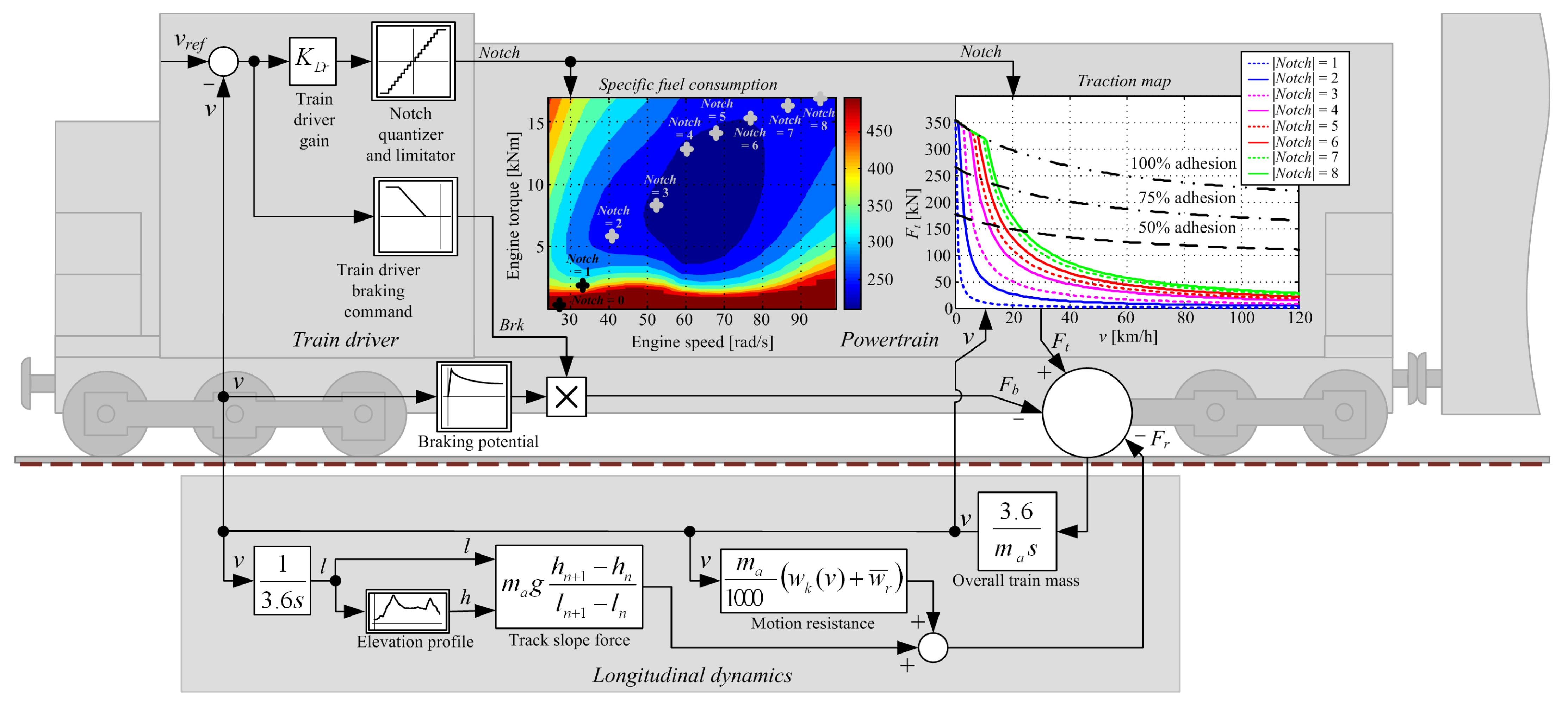
2.1. Conventional Diesel–Electric Locomotive Model

The quasi-static model of a conventional diesel–electric locomotive is based on a scalable model developed in [22], which has been derived using field measurements for a similar railway vehicle powertrain [36] and available data from the literature such as in [37]. The components of the powertrain are appropriately dimensioned to meet the traction characteristics and power requirements of the HŽ 2062 series of diesel–electric locomotives (1.6 MW, 103 t), which are currently the backbone of diesel–electric freight transport within the national railway company [38]. The locomotive mathematical model used in this study is given by the block diagram in Figure 1, and it comprises the following characteristic sub-models: train driver (engineer), locomotive powertrain, and train longitudinal dynamics, which are framed in gray.
The driver model (implemented as a proportional control term characterized with the proportional gain KDr) determines the throttle Notch position and brake command Brk using the difference between the target speed vref and the actual train speed (velocity) v, as explained in [22]. Integer Notch values, corresponding to actual discretized driver commands with 8 constant-power settings for the engine-based propulsion (see Figure 2) [37], are obtained by quantizing the driver model output. Although the braking action can be continuously controlled, it is also quantized because it would be more intuitive to implement symmetrical control actions for driving and braking, especially if using electrodynamic braking via a dissipation resistors network, which can also feature discrete dissipation power ratings for different resistor configurations [37]. Thus, the traction power command is quantized into 8 driving levels (from 1 to 8), 8 braking levels (from −1 to −8), and a single idling setting (Notch = 0). When the electrodynamic braking cannot provide sufficient braking power to maintain the train speed in the vicinity of the target speed, mechanical brakes are also engaged, as explained in [22].
The powertrain is modeled by using the static characteristics derived in [22], which are also shown in Figure 1. The engine is modeled as a static fuel consumption map that estimates the amount of fuel for selected Notch (engine power) values. The traction map block in Figure 1 denotes the traction force Ft as output, with train speed v and driver-based Notch selection used as map inputs. The traction force curves for each Notch value are derived from the traction power values (negative values would be obtained in the case of regenerative braking). This block also shows the maximum traction force of the locomotive for 100%, 75%, and 50% adhesion, thus illustrating the limiting effect of adhesion on the traction characteristic [39], which is predominant in the region of low train speeds characterized by high power demands [40]. The required electric traction power can be calculated by multiplying the traction force and the speed of the train, and the mechanical-to-electrical power conversion efficiency is shown in Figure 2. Such a definition of efficiency implicitly includes the energy consumption of on-board pumps, fans, and air compressors, and can also be used when modeling the mechanical-to-electrical energy conversion associated with regenerative braking via traction electric motors [22].
The longitudinal dynamics of the entire train in Figure 1 is represented by the movement of the lumped mass ma of the train (a point mass train representation) [22], which includes the total traction force Ft (driving or electrodynamic braking force), mechanical braking force Fb, and the resistance force due to movement and the component related to the gravitational force in the direction of motion. The motion resistance block calculates aerodynamic and rolling resistance forces where wk [N/t] and wr [N/t] are the specific resistance coefficients of longitudinal and curvature motion, respectively. These specific drag coefficients for a heavy freight train and the average curvature drag are defined in [40] as wr + wk = 29.99 + 0.0025(v + 12)2, where v is train speed (longitudinal velocity) in kilometers per hour.
The gravitational force component is calculated from the track slope and the total weight of the train as magsinα, where sinα is the ratio between the change in height and the associated distance traveled as (sinα = (hn+1hn)/(ln+1ln)).

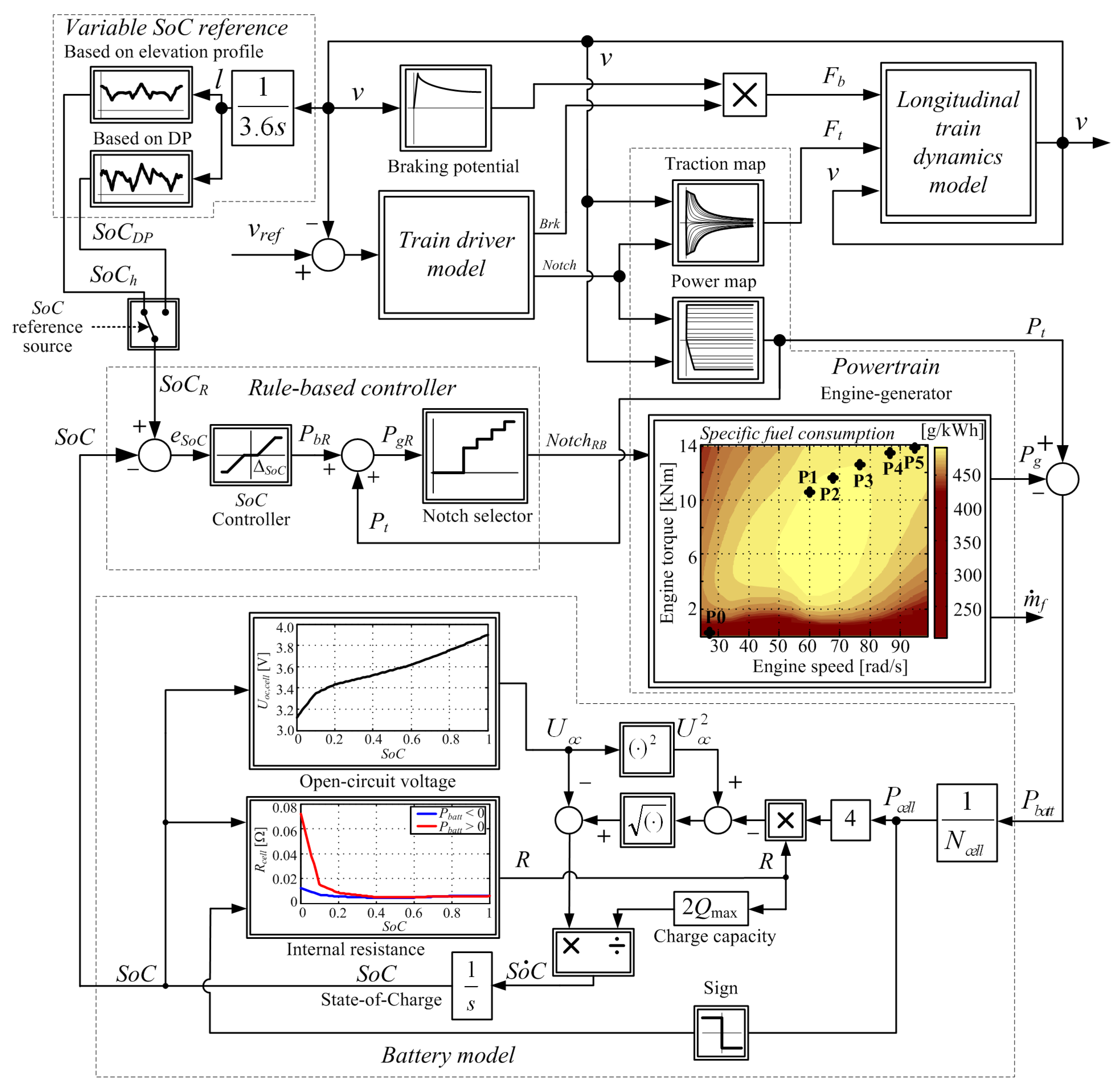
2.2. Hybrid–Electric Locomotive Model with Battery Energy Storage

The proposition of this work is that the realization of a hybrid–electric locomotive can be performed by retrofitting a conventional 103 ton (103,000 kg) locomotive equipped with a diesel–electric powertrain rated at 1.6 MW by adding an adequate battery storage system and also by reducing the engine-generator block to the same base chassis [38]. A quasi-static model of such a hybrid–electric locomotive has been developed in [22]. It is represented by a block diagram in Figure 3, which includes the same subsystems as the conventional locomotive (again modeled as static maps, see Figure 1 and Figure 2), alongside the additional battery energy storage system and its rule-based state-of-charge (SoC) controller. The model uses the same train speed and Notch input data to calculate the electrical transmission power Pt. It is also assumed that the power conversion efficiency of the battery-hybridized traction powertrain is equal to the conventional locomotive case, for simplicity reasons. The engine-generator for the battery hybrid locomotive is downsized (scaled by a factor 0.8 [22]), and it produces the electrical power Pg for each Notch setting according to Table 1 under the control of the energy management system. Note that the diesel engine operation with Notch settings 1, 2, and 3 is avoided in the case of the battery-hybridized powertrain due to relatively low power and low fuel/energy efficiency associated with those modes of operation (cf. Figure 1 and Figure 3).
The difference between the power Pg produced by the motor-generator and the transmission power Pt represents the input to the battery model which is transferred directly via a common direct current (DC) link. The battery energy storage model is derived from the battery equivalent electrical circuit of the battery electrochemical cell, as shown in [41], and its structure is illustrated by the block diagram in Figure 3. This model calculates the battery state-of-charge (SoC) based on the battery power demand and the known battery parameters (internal resistances and open-circuit voltage, whose SoC-related characteristics are also known). In this model, the positive input power values correspond to the discharge operation and the cell power is determined by dividing the total battery power by the number of battery cells Pcell = Pbatt/Ncell. The open-circuit voltage Uoc and the internal resistance R are represented by non-linear characteristics in terms of SoC (Figure 3, see also [22]). Battery sizing was previously performed in [22] and resulted in a total battery energy storage system capacity of 900 kWh, and a total weight of the battery system of 9450 kg. The battery’s aging effects and its state-of-health, which have long-term effects on the reliability and driving safety of electrified vehicles [42], have been considered by oversizing the battery to be able to meet the driving mission energy requirements within the expected calendar and cycle life of the battery system [22].
The power flow control (energy management) strategy is based on the rule-based controller shown in Figure 3 (also developed in [22]). The controller uses the required transmission power Pt and the power request PbR of the battery SoC controller to calculate the required power PgR which needs to be provided by the main motor-generator. This required power value is then passed to the Notch selector map in order to select a discrete value of NotchRB which is then used by the engine generator block. This block calculates the electrical power Pg and fuel consumption rate for each value of NotchRB according to Table 1. Note that, in the case when the requested power PgR is lower than the power produced when NotchRB = 4 is selected, the engine is put in idle mode. Although this is less fuel efficient than turning the engine off, it is more practical than the frequent on/off operation of such a heavy-duty diesel engine, which would impose increased engine maintenance requirements and would require notable re-starting power from the battery [43].
The SoC controller (Figure 3) commands the battery charging/discharging power demand. It is characterized by the proportional gain KSoC = 26,796 and a dead-zone ΔSoC = 0.26%. The latter is introduced to avoid controller output “chattering” due to noise when the control error eSoC = SoCRSoC is near zero. As indicated in [22], a variable SoC reference calculated based on the elevation profile could account for the variable potential energy of the freight train via the variable energy storage capacity (variable SoC), and has been defined as follows [22]:
S o C h = S o C b h h h min h max h min ( S o C b h S o C b l ) ,
where SoCbl = 41.51% and SoCbh = 53.63% represent the minimum and maximum values of the variable battery SoC target, in the case of a fully-loaded freight train, h is the railway track elevation profile, and hmin and hmax are its minimum and maximum values, respectively.
Therefore, a variable SoC reference is also proposed herein. However, in this work it is based on the DP optimization whose goal is to find the globally optimal state-of-charge time profile (denoted as SoCDP). This approach is also compared herein with the approach utilizing a variable SoC reference based on the elevation profile (see Figure 3).

2.3. Optimization Procedure

This section outlines the hybrid locomotive control variable optimization procedure using the dynamic programming (DP) algorithm applied to a simplified (backward-looking) model of the freight train wherein the battery state-of-charge is the only state variable.

2.3.1. Optimization Problem Formulation

The optimization goal is to minimize the energy (diesel fuel) consumption over the predefined time interval 0 ≤ ttf on the selected railway route. During this process, the transmission components’ constraints, battery SoC bounds, and the SoC terminal condition need to be always satisfied. Therefore, the cost function for this optimization problem can be defined as:
m i n   m f = t 0 t f m ˙ f ( N o t c h D P ) d t .
The above cost function is subject to the inequality constraints related to battery state-of-charge minimum and maximum values, and the traction power constraints are defined as follows:
S o C m i n S o C S o C m i n N o t c h D P , m i n N o t c h D P N o t c h D P , m a x
While also satisfying the terminal constraint corresponding to the battery charge sustainability (achieving the same battery SoC at the beginning and at the end of the driving mission):
S o C ( t 0 ) = S o C ( t f ) .
The traction power Pt is treated as the known input variable to the backward model for optimization purposes (vin(t) = Pt(t)). The control input to be optimized is the engine notch command and is defined as the control variable u(t) = NotchDP(t), taking on six discrete values corresponding to different throttle positions (see Table 1). The battery SoC and fuel mass flow dmf/dt are treated as model outputs (vector y(t) = [SoC(t) dmf/dt]T), and the battery SoC is also the only state variable within the model (i.e., x = SoC). Therefore, the process model for optimization is rewritten into the following state-space form:
x ˙ = f ( x , u , v i n ) ,
y = g ( x , u ) ,
With the scalar function, f, and the vector function, g, defined by the battery state-of-charge model, and the sub-models of the individual components of the freight train as described in the previous section.

2.3.2. Outline of Dynamic Programming Algorithm

The unique feature of the DP algorithm is that it can provide the globally optimal solution [28]. For the algorithm to be implemented, the state variable Equation (5) needs to be transformed from the continuous-time representation into its discrete-time counterpart. The Euler method of time-discretization is used to transform the continuous-time state equation into the difference equation form with the sampling time (integration step) T = 1 s [27]. The control and state variables are discretized into Nu and Nx possible values with strictly defined upper and lower bounds. Note that the NotchDP is an integer variable (NotchDP ∈ {0,4,5,6,7,8}) therefore it already assumes discrete values. The initial and final condition on the battery SoC are set to x(0) = x(tf) = 0.6479 (SoC(0) = SoC(tf) = 64.79% of the full battery charge). This value is chosen to be aligned with the starting value of the realistic energy management control strategy.
The other parameters of the DP optimization algorithm are listed in Table 2. Some of those parameters are directly related to physical constraints (such as the battery SoC bounds and cost function weighting factors), whereas others define the optimization grid density. Among the latter, the number of grid points with respect to time and control variable partitioning are predefined by the train model simulation duration tf (Nt = tf/T, T = 1 s is used herein), and throttle command discretization (Nu = 6 utilized throttle positions, see engine block in Figure 3). Thus, to achieve a reasonable trade-off between the computational time and optimization precision, a Nx = 200 grid density has been chosen for the state variable in this study. For more detailed elaboration on the DP optimization procedure, the reader is kindly referred to reference [27].

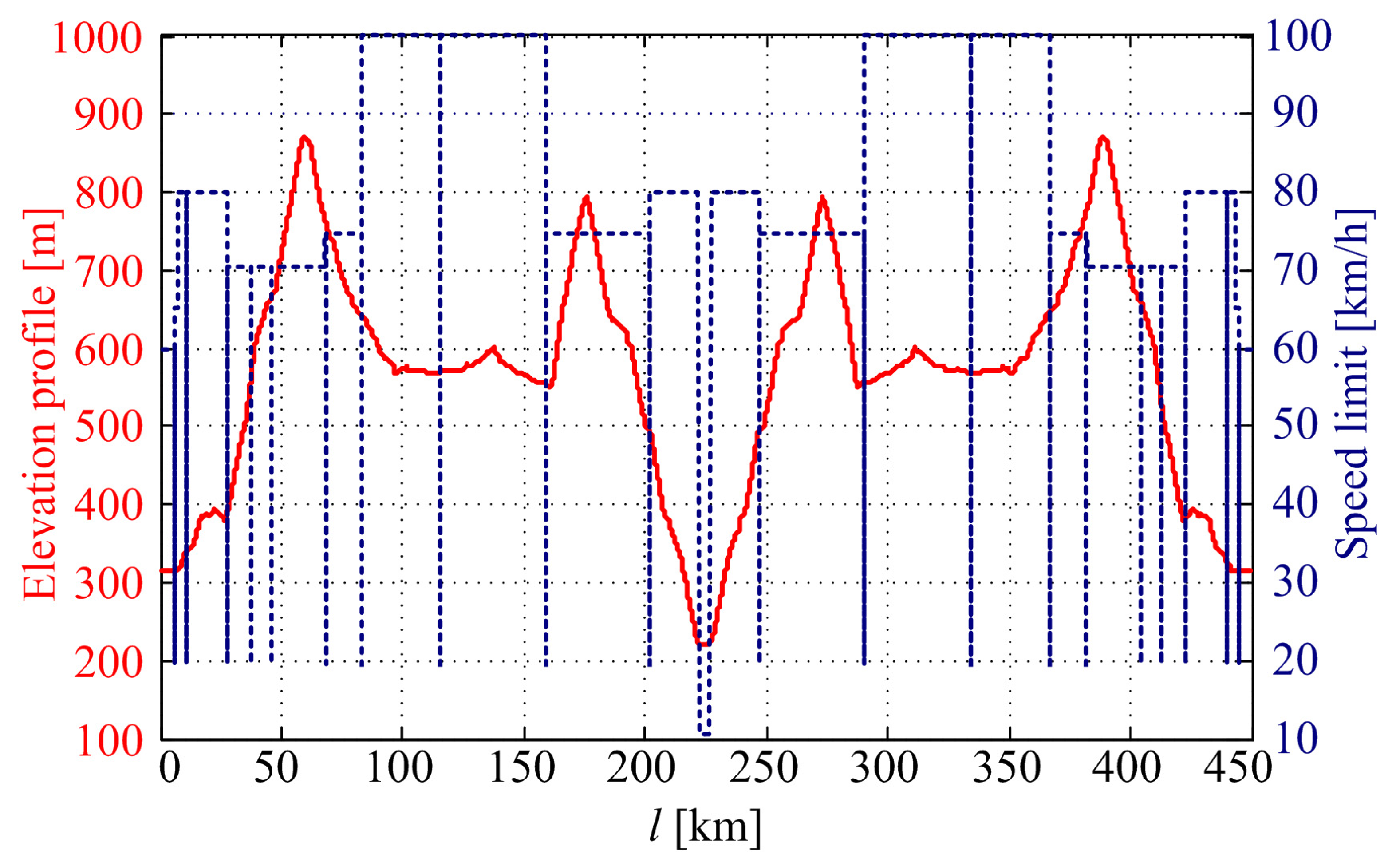
2.4. Considered Driving Mission

The railway track elevation above the sea level h (black solid line) and speed limits vlimit (green dotted line) for the mountainous railway route traversed by the freight train, during the round trip between the towns of Oštarije and Knin in the Lika region in Croatia, are shown in Figure 4. The elevation, h, and speed limits, vlimit, were defined in [22] using free online tools, such as the GPS Visualizer utility software [44] and speed limits database [45]. The considered driving scenario for the route defined in Figure 4 was carried out considering the freight train to consist of seven fully loaded 90 t cargo wagons, i.e., the maximum loading capacity of a single diesel–electric locomotive for the very railway route [38].

3. Optimization and Simulation Results

This section shows the optimization and simulation results of the fully loaded train configuration hauled by a hybrid–electric locomotive over the proposed mountainous route, compared against the conventional diesel–electric locomotive-based haul benchmark.

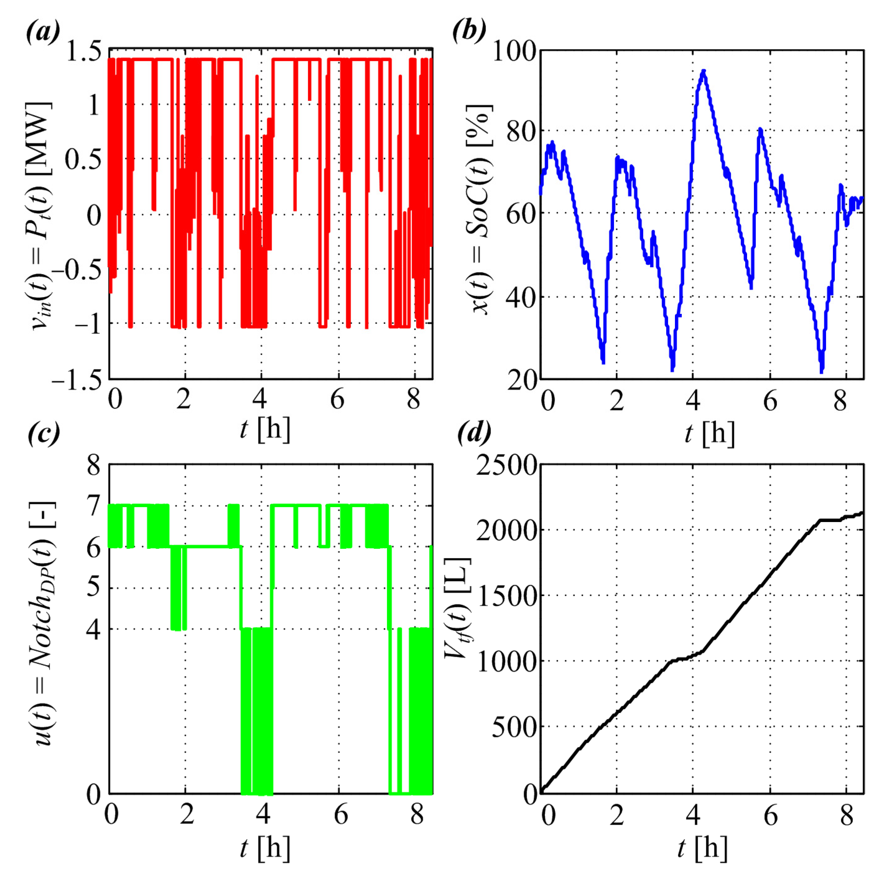
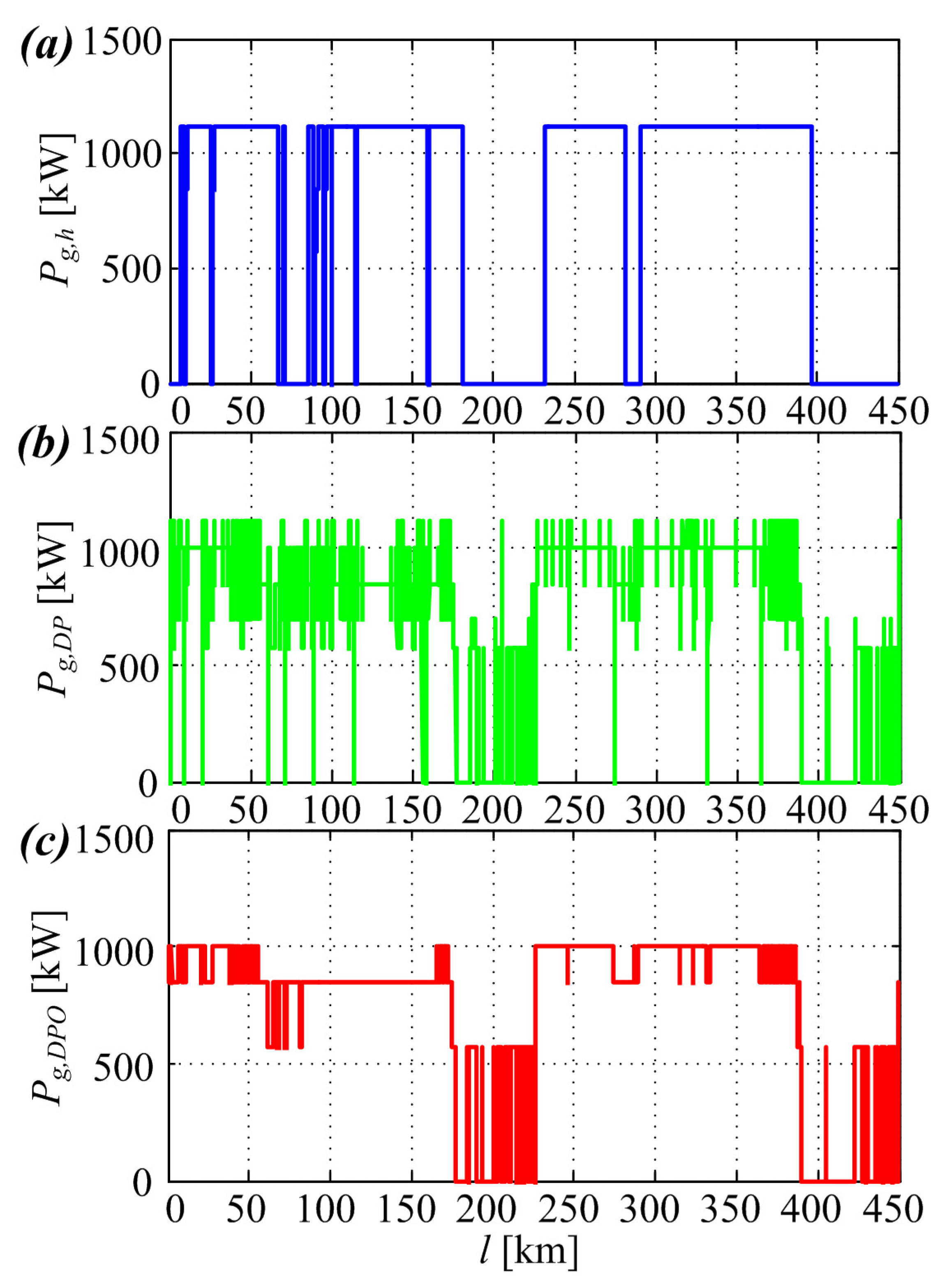
3.1. Optimization Results

Figure 5 shows the time responses of the input, control, system state, and output variables. Figure 5a shows the input vin(t) = Pt(t) of the backward model, that is, the traction power derived from the locomotive longitudinal dynamics and train driver model (Figure 1) driving over the pre-defined rail route (Figure 4). The battery SoC is the single state variable, and is shown in Figure 5b, while the optimized control variable (u(t) = NotchDP engine command) is shown in Figure 5c. The fuel consumption shown in Figure 5d is obtained by integrating the model output fuel rate as follows:
V f = 1 ρ f 0 t f m ˙ f d t ,
where ρf = 850 kg/m3 = 850 g/L is the diesel fuel density (grams per liter).
The battery SoC, shown in Figure 5b, represents the optimum SoC solution. The presented time trace shows that SoC is maintained within the prescribed bounds (Table 2). Its final value, however, is slightly below the initial one (SoC(t0) = 64.79% vs. SoC(tf) = 63.70%), although the optimization requires that the exact value SoC(tf) = 64.79% ought to be obtained at the end of the optimization cycle, i.e., SoC(t0) = SoC(tf). The latter may be ascribed to the limited resolution of the discretized variables used within the DP algorithm (i.e., DP optimization space quantization). Thus, the obtained optimal SoC solution is used as a SoC target (reference) value for the SoC controller within the hybrid locomotive model (Figure 3), which is elaborated in more detail in the next subsection.
Note also that the optimized control variable NotchDP shows that the engine operates mostly at the idling, Notch = 6, or Notch = 7 throttle positions. Notch = 4 and Notch = 5 are relatively rarely used, while the use of Notch = 8 is completely avoided. This can be attributed to the fuel efficiency of each Notch position and the power requirements, wherein Notch positions 6 and 7 both have high fuel efficiencies, while also providing ample power for the train propulsion (see engine block in Figure 3). Further note that, instead of idling, the engine may have been turned off, thereby achieving additional fuel savings. However, it would be highly impractical to have a frequent on/off operation of such a large diesel engine, as previously explained. Note also that the Notch positions below Notch = 4 (except for Notch = 0, i.e. engine idling position) are not considered because they have already been determined to be highly inefficient [22].

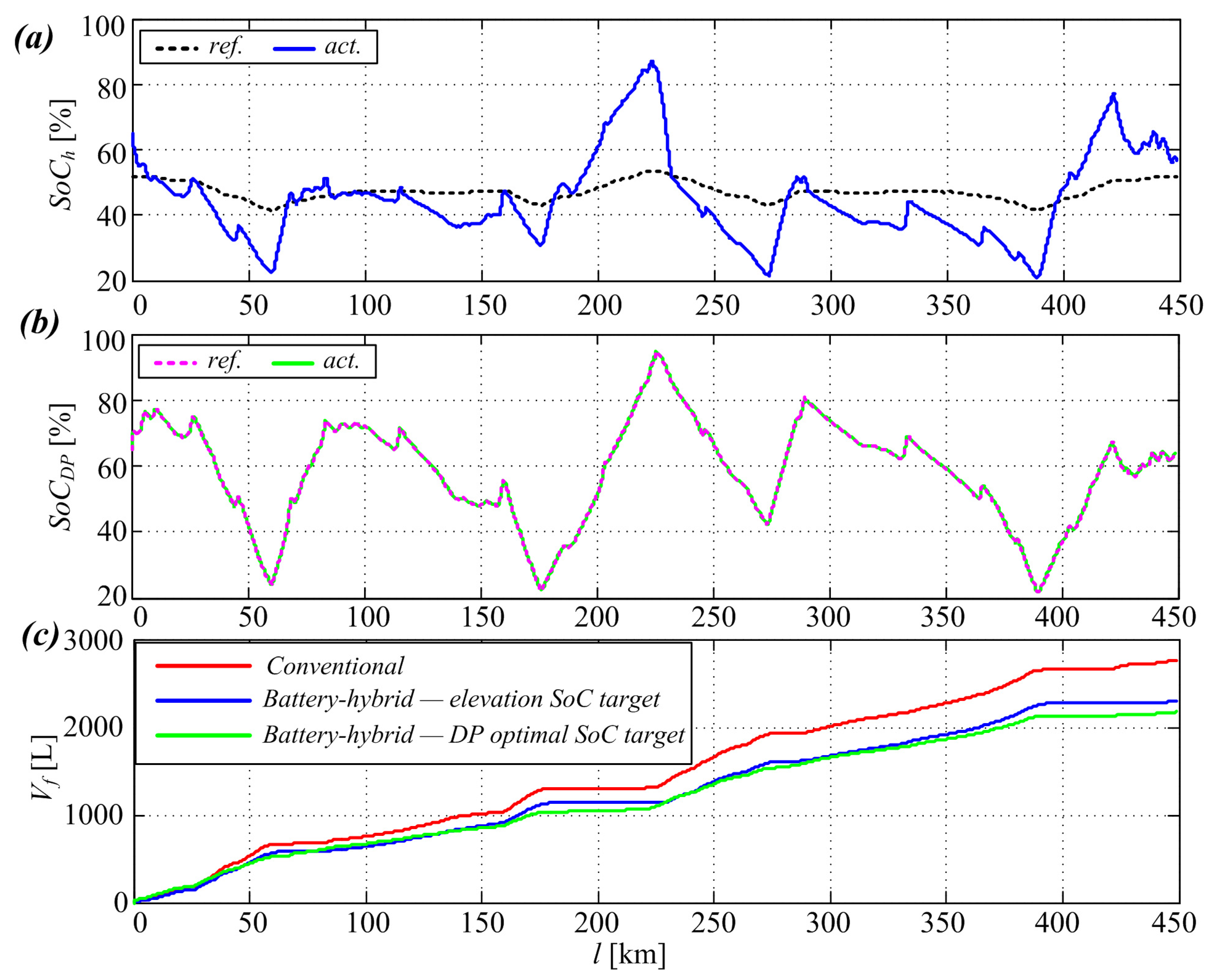
3.2. Simulation Results for the Case of Battery-Hybrid Locomotive

The driving mission of the fully loaded freight train utilizing the conventional and hybrid locomotive-based freight haul has, again, been simulated for the previously used driving scenario shown in Figure 4, which resulted in the same driving characteristics (i.e., train acceleration, velocity, and traction power requirement) due to the utilization of an identical driver model and traction characteristics. Within the battery-hybrid locomotive, the available electrical transmission power Pt includes the main electric generator power Pg and battery power Pbatt. The electric generator power production depends on the generator control strategy. Figure 6 shows the main electric generator power production Pg for the three different control strategies considered herein. In particular, Figure 6a shows the power production of the generator Pg,h when the SoC reference is calculated based on the elevation profile alone, Figure 6b shows the power production of the generator Pg,DP when SoC reference is based on the DP optimization results, and Figure 6c shows the power production of the generator Pg,DPO within the DP optimization framework. In all above cases, the power production is directly related to Notch commands according to Table 1.
Figure 7 shows the simulation results of the comparative freight train driving missions with the conventional diesel–electric locomotive hauling used as a benchmark against which the battery-hybrid locomotive equipped with rule-based powertrain control is analyzed (see Figure 3 and reference [22]). Figure 7a shows the SoC trace when the elevation-profile-based state-of-charge reference SoCh from [22] is used, while the battery SoC trace for the case of DP-optimal SoCDP reference is shown in Figure 7b. In the case when the freight train is accelerating and climbing, the generator predominantly covers the high power requirements (cf. Figure 4 and Figure 6). In the latter case, however, the maximum output power of the downsized diesel engine cannot fully cover the required traction power, which mandates an additional discharging of the battery energy storage, whose SoC starts to decrease in turn (cf. Figure 4 and Figure 6). In the case when the regenerative braking regime is commanded to the power train (e.g., for the purpose of decelerating the freight train or to maintain constant train velocity during driving downhill), the battery energy storage takes on the excess power for its charging and its SoC is thus increased. The results in Figure 6a show that, in the case when the SoC reference is based on elevation profile alone, the engine operates between a fully open throttle and idling. This is due to the use of the rather unfeasible SoC reference based on elevation profile alone, although this type of SoC reference has been shown to yield better results compared to the case when a constant SoC value is used [22]. Therefore, when the actual SoC value is below the reference, the engine-generator tries to compensate by operating at full power (cf. Figure 6a and Figure 7a).
On the other hand, when the DP optimal SoCDP reference is used, the SoC target following is much more effective (see Figure 7b) and the engine-generator set operates at lower power settings (see Figure 6b). This is because the SoCDP reference represents a feasible solution obtained by the DP optimization and the SoC controller can follow it closely. As mentioned above, in the case when the DP-optimization-based SoC reference is used, the engine-generator set operates at more efficient throttle positions (i.e., below the maximum power), thus outputting lower power at higher fuel efficiencies (cf. Figure 6 and the engine-generator block in Figure 3).
As expected, the variable SoCDP target results in better SoC following compared to the case of the elevation-based SoCh target because, in the former case, the SoC target is adjusted according to the optimization rules which consider the powertrain constraints. Moreover, the SoCDP reference also results in an improvement in fuel efficiency (cf. Table 2) that is very close to the optimization result, denoted as SoCDPO. Figure 7c shows the comparative fuel consumption plots for the conventional locomotive and its battery-hybrid counterparts with battery SoCh and SoCDP reference adjustment.

4. Discussion

The final aggregate fuel consumption results are listed in Table 3, illustrating the advantages of a locomotive powertrain equipped with battery energy storage in terms of fuel consumption reduction when optimized SoC target adaptation is used. In particular, the fuel efficiency of the already quite efficient battery-hybrid diesel electric locomotive has been further improved by about 7.2% through using the offline-optimized battery SoC reference trajectory. Moreover, its fuel efficiency, with respect to the locomotive with conventional diesel–electric traction, is improved by about 22.9%. Due to the inherent determinism of rail transport, such as its known timetables and parameters of train configurations, as well as the a priori known profile of the railway line, this approach may be able to notably increase the efficiency of hybrid electric locomotive-based traction and further reduce the fuel consumption of the hybridized rolling stock.
Therefore, it can be concluded that:
  • The model can predict the effect of different SoC target values on fuel consumption;
  • For the optimized SoC target values, the controller can maintain battery SoC within the prescribed bounds while honoring the SoC boundary condition, while simultaneously achieving optimal fuel consumption;
  • The energy management strategy can be significantly enhanced by simply incorporating the desired battery SoC trajectory data obtained by means of the DP optimization.
Note, however, that rail freight hauling might be sensitive to load variations (see [40]), and rail vs. wheel adhesion characteristics, as indicated in [46]. Even though this aspect of railway freight haul has not been investigated here, it represents the next step in the optimization analysis of railway freight haul for both conventional and battery-hybridized locomotive-based traction. Furthermore, the verification of the proposed approach would largely benefit from the collection of representative experimental data from the currently operating conventional diesel–electric locomotive fleet, which could then serve as a realistic benchmark for the validation of the proposed optimization study. However, such field testing requires substantial preparations and is subject to stringent time and safety constraints, as well as security and confidentiality requirements due to the specific nature of rail freight business operations.

5. Conclusions

In this paper, the previously developed model of the battery-hybrid diesel–electric locomotive used for heavy freight haul over a demanding mountainous railway route is extended with an additional optimized battery state-of-charge (SoC) reference for the locomotive energy management system. The optimal SoC trajectory has been obtained by means of a dynamic programming (DP) optimization algorithm incorporating a priori known and readily available railway track elevation and speed limits profiles. The thus-obtained SoC trajectory has been subsequently fed to the battery SoC controller to calculate the required engine throttle control action during freight haul over the demanding mountainous railway track. The resulting throttle commands are ultimately used within the freight train model to simulate the behavior of the hybridized locomotive power train and to evaluate its fuel consumption.
The overall results have shown that if the optimized SoC target values are used in the energy management strategy then an additional 7.2% gain of the hybridized powertrain fuel efficiency can be expected, whereas the fuel savings obtained compared to the conventional diesel–electric locomotive-based freight haul reach 22.9%. The potential advantage of such an approach is in the inherent determinism of the rail freight haul, whose key parameters are related to the freight train configuration and the overall load, and in the a priori known railway line configuration (i.e., its elevation profile). Thus, the proposed approach could notably increase the energy (fuel) efficiency of the hybridized rolling stock, especially over the demanding railway routes characterized by notable elevation variations.
Future work may entail the numerical optimization of different driving mission velocity profiles and different loads to investigate whether the optimal SoC trajectory can be determined from the physical railway track profile, speed limitations, and other train configuration parameters and control strategy robustness analysis, especially regarding variable traction conditions on the railway track. Moreover, the current study could be further expanded through recording the representative experimental data from the currently operating conventional diesel–electric locomotive fleet, which would then serve as a realistic benchmark case.

Author Contributions

Conceptualization, M.C. and D.P.; methodology, M.C. and Z.K.; software, M.C.; validation, M.C., D.P. and Z.K.; formal analysis, Z.K.; investigation, D.P. and Z.K.; resources, D.P.; writing—original draft preparation, M.C.; writing—review and editing, D.P. and Z.K.; visualization, M.C.; supervision, D.P.; project administration, D.P.; funding acquisition, D.P. All authors have read and agreed to the published version of the manuscript.

Funding

It is gratefully acknowledged that this research has been supported by the European Regional Development Fund under the grant KK.01.1.1.01.0009 (DATACROSS).

Data Availability Statement

Research data can be made available for non-profit use in research and education upon a formal request made to the corresponding author.

Conflicts of Interest

The authors declare no conflict of interest.

References

  1. Ritchi McCollum, D.; Krey, V.; Kolp, P.; Nagai, Y.; Riahi, K. Transport electrification: A key element for energy system transformation and climate stabilization. Clim. Change 2014, 123, 651–664. [Google Scholar] [CrossRef]
  2. Saber, A.Y.; Venayagamoorthy, G.K. Plug-in Vehicles and Renewable Energy Sources for Cost and Emission Reductions. IEEE Trans. Ind. Electron. 2011, 58, 1229–1238. [Google Scholar] [CrossRef]
  3. Hansen, J.; Sato, M.; Kharecha, P.; Beerling, D.; Berner, R.; Masson-Delmotte, V.; Pagani, M.; Raymo, M.; Royer, D.L.; Zachos, J. Target atmospheric CO2: Where should humanity aim? Open Atmos. Sci. J. 2008, 2, 217–231. [Google Scholar] [CrossRef]
  4. Buzzonii, L.; Pede, G. New Prospects for Public Transport Electrification. In Proceedings of the International Conference on Electrical Systems for Aircraft, Railway and Ship Propulsion (ESARS), Bologna, Italy, 16–18 October 2012. [Google Scholar] [CrossRef]
  5. Shakya, S.R.; Shrestha, R.M. Transport sector electrification in a hydropower resource rich developing country: Energy security, environmental and climate change co-benefits. Energy Sustain. Dev. 2011, 15, 147–159. [Google Scholar] [CrossRef]
  6. Deur, J.; Škugor, B.; Cipek, M. Integration of Electric Vehicles into Energy and Transport Systems. Autom. J. Control. Meas. Electron. Comput. Commun. 2015, 56, 395–410. [Google Scholar] [CrossRef]
  7. Spiryagin, M.; Cole, C.; Sun, Y.Q.; McClanachan, M.; Spiryagin, V.; McSweeney, T. Design and Simulation of Rail Vehicles; Taylor & Francis Group, LLC: Abingdon, UK, 2014; ISBN 978-11-380-7370-8. [Google Scholar]
  8. Frey, S. Railway Electrification Systems & Engineering, 1st ed.; White Word Publications: New Delhi, India, 2012; ISBN 978-81-323-4395-0. [Google Scholar]
  9. Mandić, M.; Uglešić, I.; Milardić, V.; Filipović-Grčić, B. Application of Regenerative Braking on Electrified Railway Lines in AC Traction Systems 25 kV, 50 Hz. In Proceedings of the 12th Symposium HRO CIGRÉ, Šibenik, Croatia, 8–11 November 2015. [Google Scholar]
  10. Electrified Railway Lines—European Commission. Available online: https://ec.europa.eu/transport/facts-fundings/scoreboard/compare/energy-union-innovation/share-electrified-railway_en#2016 (accessed on 20 April 2020).
  11. Isler, C.A.; Blumenfeld, M.; Roberts, C. Assessment of railway infrastructure improvements: Valuation of costs, energy consumption and emissions. Sustain. Energy Technol. Assess. 2022, 52 Pt B, 102179. [Google Scholar] [CrossRef]
  12. Roskilly, A.P.; Palacin, R.; Yan, J. Novel technologies and strategies for clean transport systems. Appl. Energy 2015, 157, 563–566. [Google Scholar] [CrossRef]
  13. Verma, S.; Upadhyay, R.; Shankar, R.; Pandey, S.P. Performance and emission characteristics of micro-algae biodiesel with butanol and TiO2 nano-additive over diesel engine. Sustain. Energy Technol. Assess. 2023, 55, 102975. [Google Scholar] [CrossRef]
  14. Dominković, D.F.; Bačeković, I.; Pedersen, A.S.; Krajačić, G. The future of transportation in sustainable energy systems: Opportunities and barriers in a clean energy transition. Renew. Sustain. Energy Rev. 2018, 82, 1823–1838. [Google Scholar] [CrossRef]
  15. Cosic, A. Hybrid Locomotive, SUSTRAIL—FP7 Project Deliverable 3.2.1, 265740 FP7—THEME [SST.2010.5.2-2.]. 2014. Available online: https://www.sustrail.eu/IMG/pdf/d3.2-v1-hybrid_locomotive-final_version.pdf (accessed on 24 May 2023).
  16. Rastegarzadeh, S.; Mahzoon, M.; Mohammadi, H. A novel modular designing for multi-ring flywheel rotor to optimize energy consumption in light metro trains. Energy 2020, 206, 118092. [Google Scholar] [CrossRef]
  17. Liu, H.; Chen, G.; Xie, C.; Li, D.; Wang, J.; Li, S. Research on energy-saving characteristics of battery-powered electric-hydrostatic hydraulic hybrid rail vehicles. Energy 2020, 205, 118079. [Google Scholar] [CrossRef]
  18. Meinert, M.; Prenleloup, P.; Schmid, S.; Palacin, R. Energy storage technologies and hybrid architectures for specific diesel driven rail duty cycles: Design and system integration aspects. Appl. Energy 2015, 157, 619–629. [Google Scholar] [CrossRef]
  19. Yang, J.; Xu, X.; Peng, Y.; Zhang, J.; Song, P. Modeling and optimal energy management strategy for a catenary battery-ultracapacitor based hybrid tramway. Energy 2019, 183, 1123–1135. [Google Scholar] [CrossRef]
  20. Liu, H.; Jiang, Y.; Li, S. Design and downhill speed control of an electric-hydrostatic hydraulic hybrid powertrain in battery-powered rail vehicles. Energy 2019, 187, 115957. [Google Scholar] [CrossRef]
  21. Sun, Y.; Cole, C.; Spiryagin, M.; Godber, T.; Hames, S.; Rasul, M. Conceptual designs of hybrid locomotives for application as heavy haul trains on typical track lines. Proc. Inst. Mech. Eng. Part F J. Rail Rapid Transit 2013, 227, 439–452. [Google Scholar] [CrossRef]
  22. Cipek, M.; Pavković, D.; Kljaić, Z.; Mlinarić, T.J. Assessment of Battery-Hybrid Diesel-electric Locomotive Fuel Savings and Emission Reduction Potentials based on a Realistic Mountainous Rail Route. Energy 2019, 173, 1154–1171. [Google Scholar] [CrossRef]
  23. Technical Report: Hybrid Locomotive—SUSTRAIL, FP7 No. 265740, Deliverable 3.2.1. 2014. Available online: http://www.sustrail.eu/IMG/pdf/d3.2-v1-hybrid_locomotive-final_version.pdf (accessed on 20 April 2020).
  24. Donnelly, F.W.; Cousineau, R.L.; Horsley, R.N.M. Hybrid Technology for the Rail Industry, Rail Conference, 2004. In Proceedings of the 2004 ASME/IEEE Joint, Baltimore, MD, USA, 6–8 April 2004. [Google Scholar] [CrossRef]
  25. Gao, Y.; Ehsani, M.; Miller, J.M. Hybrid Electric Vehicle: Overview and state of the Art. In Proceedings of the IEEE International Symposium on Industrial Electronics, Dubrovnik, Croatia, 20–23 June 2005; pp. 307–315. [Google Scholar]
  26. Guzzella, L.; Sciarretta, A. Vehicle Propulsion Systems—Introduction to Modeling and Optimisation, 2nd ed.; Springer: Berlin/Heidelberg, Germany, 2007. [Google Scholar]
  27. Cipek, M.; Kasać, J.; Pavković, D.; Zorc, D. A novel cascade approach to control variables optimization for advanced series-parallel hybrid electric vehicle power-train. Appl. Energy 2020, 276, 115488. [Google Scholar] [CrossRef]
  28. Bellman, R.E.; Dreyfus, S.E. Applied Dynamic Programming; Princeton University Press: Princeton, NJ, USA, 1962. [Google Scholar]
  29. Hofman, T.; Van Druten, R.; Serrarens, A.; Steinbuch, M. Rule-based energy management strategies for hybrid vehicles. Int. J. Electr. Hybrid Veh. 2007, 1, 71–94. [Google Scholar] [CrossRef]
  30. Zhou, Y.; Ravey, A.; Péra, M.-C. Multi-mode predictive energy management for fuel cell hybrid electric vehicles using Markov driving pattern recognizer. Appl. Energy 2020, 258, 114057. [Google Scholar] [CrossRef]
  31. Hou, D.; Sun, Q.; Bao, C.; Cheng, X.; Guo, H.; Zhao, Y. An all-in-one design method for plug-in hybrid electric buses considering uncertain factor of driving cycles. Appl. Energy 2019, 253, 113499. [Google Scholar] [CrossRef]
  32. Hou, J.; Song, Z. A hierarchical energy management strategy for hybrid energy storage via vehicle-to-cloud connectivity. Appl. Energy 2020, 257, 113900. [Google Scholar] [CrossRef]
  33. Mahmoudimehr, J.; Sebghati, P. A Novel Multi-objective Dynamic Programming Optimization Method: Performance Management of a Solar Thermal Power Plant as a Case Study. Energy 2018, 168, 796–814. [Google Scholar] [CrossRef]
  34. Hajipour, E.; Mohiti, M.; Farzin, N.; Vakilian, M. Optimal Distribution Transformer Sizing in a Harmonic Involved Load Environment via Dynamic Programming Technique. Energy 2016, 120, 92–105. [Google Scholar] [CrossRef]
  35. Mia, S.; Podder, A.K.; Kumar, M.N.; Bhatt, A.; Kumar, K. Experimental verification of a dynamic programming and IoT-based simultaneous load-sharing controller for residential homes powered with grid and onsite solar photovoltaic electricity. Sustain. Energy Technol. Assess. 2023, 55, 102964. [Google Scholar] [CrossRef]
  36. Fritz, S.G. Evaluation of Biodiesel Fuel in an EMD GP38-2 Locomotive, NREL REPORT/PROJECT NUMBER: SR-510-33436, May 2004. Available online: https://www.nrel.gov/docs/fy04osti/33436.pdf (accessed on 24 May 2023).
  37. Valter, Z. Diesel-Electric Locomotives; Školska knjiga Zagreb: Zagreb, Croatia, 1985; ISBN 978-953-0-30697-4. (In Croatian) [Google Scholar]
  38. Škrobonja, D.; Beraković, T.; Božunović, A.; Ljubaj, Z.; Ljubaj, N. Applicative Monitoring of Locomotive Diesel Engine Oil, Professional paper. Fuels Lubr. 2004, 43, 291–309. Available online: https://hrcak.srce.hr/7174 (accessed on 19 January 2023).
  39. Pichlík, P.; Zděnek, J. Overview of Slip Control Methods Used in Locomotives. Trans. Electr. Eng. 2014, 3, 38–43. [Google Scholar]
  40. Kljaić, Z.; Cipek, M.; Pavković, D.; Mlinarić, T.J. Assessment of Railway Train Energy Efficiency and Safety Using Real-time Track Condition Information. J. Sustain. Dev. Energy Water Environ. Syst. 2021, 9, 1080352. [Google Scholar] [CrossRef]
  41. Bin, Y.; Li, Y.; Feng, N. Nonlinear dynamic battery model with boundary and scanning hysteresis. In Proceedings of the ASME 2009 Dynamic Systems and Control Conference, Hollywood, CA, USA, 12–14 October 2009; No. DSCC2009-2745. pp. 245–251. [Google Scholar] [CrossRef]
  42. Ouyang, T.; Wang, C.; Xu, P.; Ye, J.; Liu, B. Prognostics and health management of lithium-ion batteries based on modeling techniques and Bayesian approaches: A review. Sustain. Energy Technol. Assess. 2023, 55, 102915. [Google Scholar] [CrossRef]
  43. Malla, S.G.; Bhende, C.N. Enhanced operation of stand-alone “Photovoltaic-Diesel Generator-Battery” system. Electr. Power Syst. Res. 2014, 107, 250–257. [Google Scholar] [CrossRef]
  44. GPS Visualizer: Freehand Drawing Utility: Draw on a Map and Save GPX Data. Available online: https://www.gpsvisualizer.com/draw/ (accessed on 19 January 2023).
  45. OpenRailwayMap. Available online: https://www.openrailwaymap.org/ (accessed on 19 January 2023).
  46. Pavković, D.; Cipek, M.; Kljaić, Z.; Mlinarić, T.J. A fuzzy logic-based classifier for railway track condition estimation and tractive effort conditioning using data from remote sensors. In Proceedings of the XXIV International Conference on Material Handling, Constructions and Logistics—MHCL ’22, Belgrade, Serbia, 21–23 September 2022. [Google Scholar]
Figure 1. Principal block diagram model of conventional diesel–electric locomotive.
Machines 11 00589 g001
Figure 2. Locomotive output power vs. notch lever position and electric power conversion efficiency [22].
Machines 11 00589 g002
Figure 3. Block diagram of hybrid–electric locomotive quasi-static model (see [22]).
Machines 11 00589 g003
Figure 4. Railway route longitudinal profile from [22].
Machines 11 00589 g004
Figure 5. Input variables of backward-looking model (a), state variable (b), optimized control variable (c), and output fuel consumption (d).
Machines 11 00589 g005
Figure 6. Power production of main generator using SoC reference based on elevation profile (a), using SoC reference based on DP optimization (b), and DP-based optimization result (c).
Machines 11 00589 g006
Figure 7. Battery SoC when elevation profile is used for SoC reference profile generation (a), battery SoC when DP optimization is used for SoC target generation (b), and aggregate fuel consumptions of conventional diesel–electric locomotive and battery-hybrid diesel–electric locomotive (c).
Machines 11 00589 g007
Table 1. Hybrid–electric locomotive scaled diesel engine and generator set data from [22].
Throttle PositionMain Engine Power Pmg (kW)Generator Power Pg (kW) Fuel   Rate   m ˙ f   ( g / s )
P0—IDLE6.4302.5704
P1—Notch 4632.77566.4940.8315
P2—Notch 5787.15694.1351.6475
P3—Notch 6965.83844.7064.2834
P4—Notch 71161.701004.7379.8195
P5—Notch 81312.801121.6794.4690
Table 2. DP optimization parameters.
ParameterValue
Lower SoC bound SoCmin0.20 (20%)
Upper SoC bound SoCmax0.95 (95%)
Grid points with respect to time Nt30694
Grid points with respect to control input Nu6
Grid points with respect to state variable Nx200
Table 3. Comparative SoC and fuel consumption data from simulation.
LocomotiveBattery SoC [%]Fuel Consumption [L]
SoC(t0)SoC(tf)Vf
Conventional--2761
Hybrid (SoCh)64.7956.732295
Hybrid (SoCDP)64.7963.812130
Hybrid (SoCDPO)64.7963.702119
Disclaimer/Publisher’s Note: The statements, opinions and data contained in all publications are solely those of the individual author(s) and contributor(s) and not of MDPI and/or the editor(s). MDPI and/or the editor(s) disclaim responsibility for any injury to people or property resulting from any ideas, methods, instructions or products referred to in the content.

