
Design and Simulation Analysis of Docking Interface of Linked In-Orbit Replacement Module

1
School of Mechanical Engineering, University of Science and Technology Beijing, Beijing 100083, China
2
Beijing Institute of Spacecraft System Engineering, Beijing 100094, China
*
Author to whom correspondence should be addressed.
Machines 2023, 11(4), 491; https://doi.org/10.3390/machines11040491
Submission received: 5 March 2023
/
Revised: 4 April 2023
/
Accepted: 5 April 2023
/
Published: 19 April 2023
(This article belongs to the Section Machine Design and Theory)
Abstract
:On-orbit service for spacecraft relies heavily on on-orbit docking with the orbital replacement unit docking interface. Foreign research on the docking interface of the orbit replaceable unit has been in-depth, while the domestic work is still limited. Currently, most design on the docking interface relies on the axial feed of the manipulator, which may result in insufficient docking interface mating force under specific conditions. In view of the above problems, it requires a linear plug-in locking interface for the docking of the orbital replaceable unit, and the design scheme of the tapered rod guide and linkage locking parts needs to be determined. Optimization of the linkage locking mechanism is completed by a finite element simulation. The effect of clearance of the taper rod, effective locking points and friction coefficient have been analyzed by means of dynamics modelling during the docking and locking processes. The research also verified the design rationality for the orbital replaceable unit linkage. A processing path and verification for the prototype have been made as well. This work introduces the idea of self-plugging during the orbital docking process. It lays a foundation for the prototype development and control strategy of the orbital replaceable unit.
1. Introduction
The ORU (orbital replaceable unit) is packaged with spacecraft components or standalone, and has an on-orbit replaceable function. The design of the butt locking mechanism is the most important part of the ORU mission. A variety of ORU butt locking mechanisms have been designed and studied internationally. Typical mechanical interfaces include snap-on, conical rod and claw [1,2,3,4].
The snap-on interface is very compact and requires high control of the robotic arm, because it has no components that can implement envelope capture functions. ISSI (Intelligent Space System Interface) is a typical snap-on interface, jointly developed by several units such as SLA (Aerospace and Lightweight Structure) and RWTH (RWTH Aachen University) [5]. The first-generation SIROM (Standard Interface for Robotic Manipulation of payloads in future space missions) developed by the European Union in 2016 is also a snap-on interface [6]. The cone-rod interface has the advantages of simple structure, light weight, large docking tolerance and easy control, but it also relies on the control of the robotic arm [7]. The cone-rod interface is used in the “Orbital Express” project proposed by the US Defense Advanced Research Projects Agency in 1999 [8]. Taper-rod interfaces are also used in the “ROSE” program [9], “CX-OLEV” program [10] and ASSIST installations [11]. The gripper interface can achieve a wide range of envelope capture through the docking gripper, and the control difficulty of the space manipulator is reduced. But this kind of interface takes up a lot of physical space. The JEM-EF (Japanese Experiment Module Exposed Facility) [12] and the second generation SIROM also adopt the claw interface [13].
The currently designed interface docking process relies on the robotic arm [14,15], which will result in insufficient docking force. In view of the above problems, a plug-in locking interface that does not rely on the mechanical arm is designed. The guide mechanism of ORU is generally by cone-rod [16,17,18,19]. Only a small number of scholars have studied the design of the guide cone aperture, cone angle and cone configuration. Li [20] obtained a new arc-shaped guide cone by improving the plane cone surface. Qi [21] transformed the three-dimensional space search problem into a two-dimensional plane solution through the cross-section method. Ping [22] established a theoretical model of the docking angle through force analysis. In addition, Hays [23] and Han W [24] also studied the design of the guide cone. The above-mentioned scholars all designed single-cone guiding processes, and did not consider the situation of double-rod guiding. The docking process of the guiding mechanism and the locking mechanism is complicated, and it is difficult to solve it by analytical methods. Therefore, many institutions use kinetic analysis software to analyze the docking process. Scholars have used dynamic analysis and design system (DADS) software to simulate the capture and recovery process [25] in the “Orbital Express” plan.
The docking kinetic model was established in detail by the NASA research institute. Various ground simulation test platforms have been established by NASA [26]. Scholars from various countries have analyzed the docking process through dynamic analysis software. A. Boesso [27] ensured the effectiveness of the docking system through the multi-body dynamics analysis software ADAMS. Ma [28] verified that the claw-type docking mechanism can achieve reliable capture and docking through dynamic simulation. Valle S C [29] developed a series of optimal, linear and nonlinear, continuous and impulsive guidance and control techniques. The above scholars provided ideas for the dynamic simulation of the docking process. But they did not analyze the two-bar guiding process or the locking process.
The traditional docking interface mostly depends on the control of the manipulator. The accuracy and reliability of the docking are affected by the accuracy of the manipulator. A docking interface that does not rely entirely on the control of the manipulator is designed to reduce the error caused by the manipulator. The docking interface can actively realize axial feed. The docking interface includes a guide assembly and a locking assembly. The structure is optimized by simulation analysis. The guidance and locking process has been targeted for simulation analysis combined with the characteristics of the design scheme. The above contents lay the initial foundation for the design of the docking interface and the development of the prototype.
2. Design of Docking Interface
2.1. Guide Assembly
The cone-rod guiding mechanism has the advantages of simple mechanism, relatively light weight and controllable tolerance. Therefore, the cone-rod guide mechanism is adopted. According to Li‘s research results [30], The connection strength between two guide rods and three guide rods is not much different. An increase in the number of guide rods will complicate the docking process. The possibility of docking process failure will increase. Therefore, the double-rod guidance scheme is adopted.
The design of the guide rod is simple. The body of the guide rod is designed to be cylindrical, and the rod head is designed to be hemispherical. The opening diameter of the cone is an important parameter for successful docking. It is assumed that the envelope point of the guide rod head is. If the space translation is, The three-dimensional translation is transformed into:
Further:
When the rotation angle of the ORU around the axis is α,
When the rotation angle of the ORU around the axis is ,
When the rotation angle of the ORU around the axis is ,
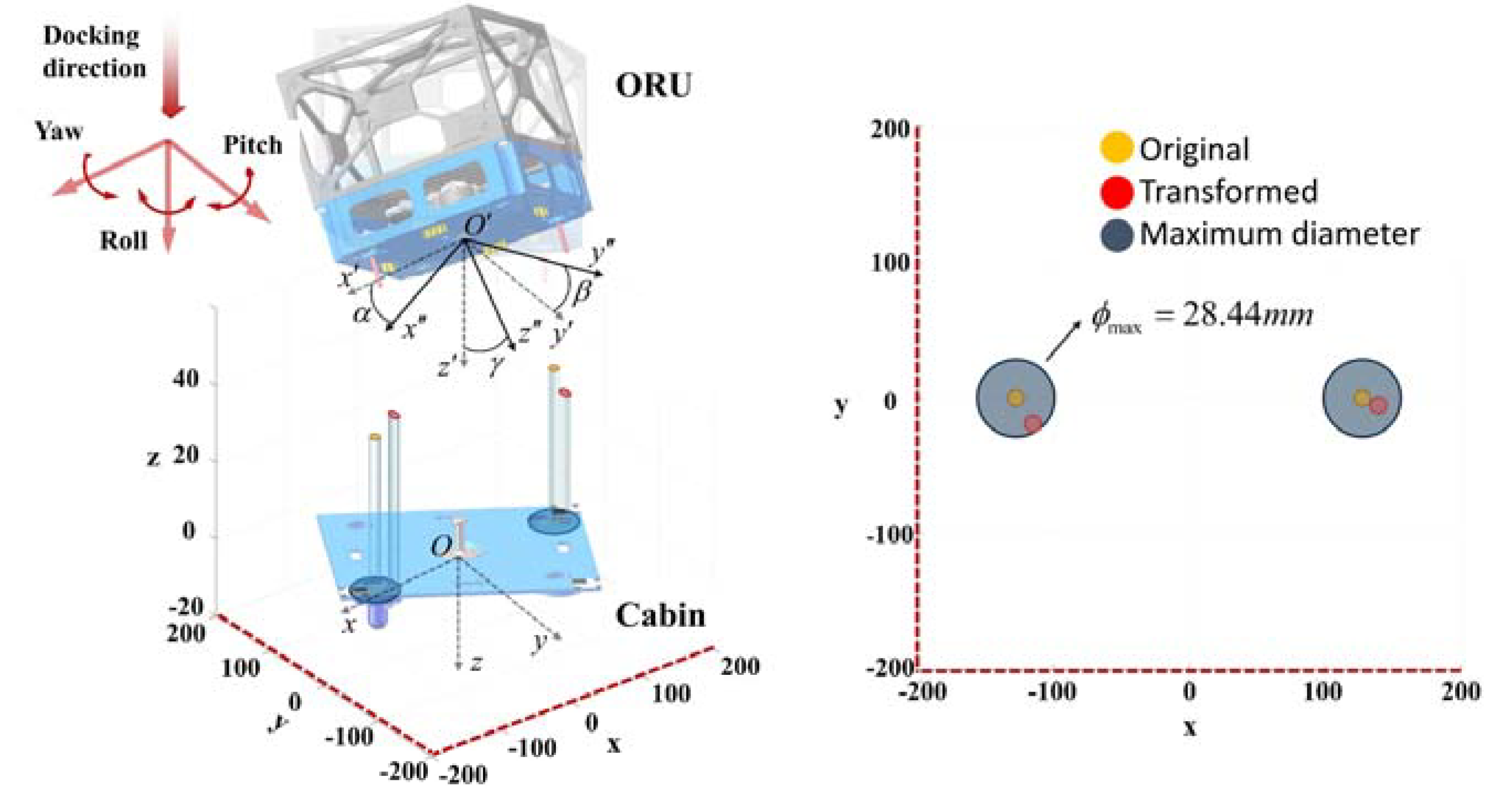
The docking surface of the ORU is named the cabin surface. The global coordinate system is established based on the surface center of the cabin. The global coordinate system is established based on the surface center of the ORU.
The angle deviation between the ORU and the cabin in three directions (x, y, z) is 1° and the radial tolerance is ±5 mm. As shown in Figure 1, the red circle is obtained, according to the above space coordinate transformation principle. The red circle is projected onto the plane. When the distance between the two docking surfaces is 40 mm and the size of the ORU is 260 mm × 260 mm × 260 mm, The diameter of the cone mouth is 28.50 mm by MATLAB numerical solution.
2.2. Locking Component
Structural Design
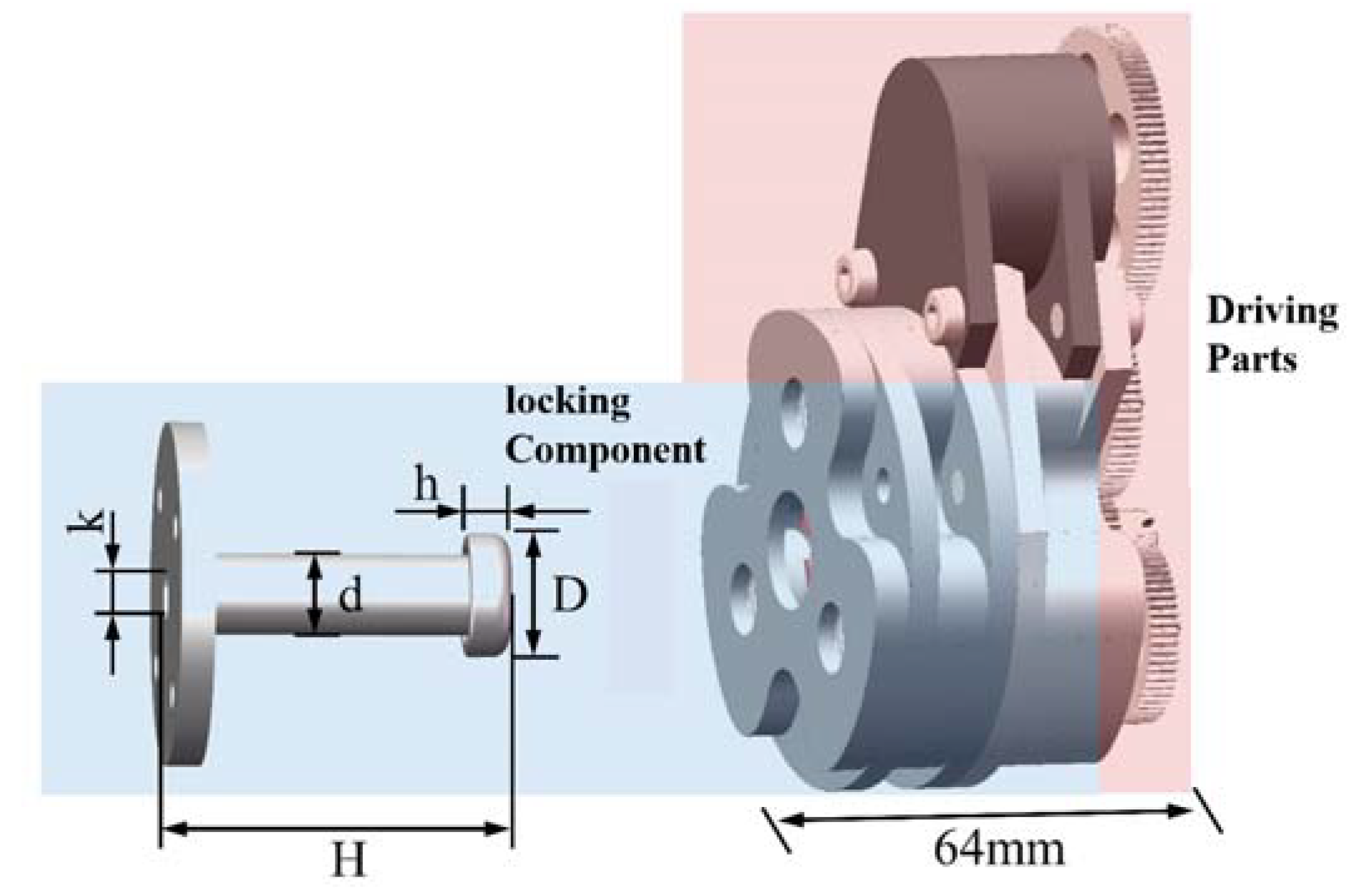
The overall structure of the locking component is shown in Figure 2. The locking component is flat in order to save space. The locking components include the locking rod, locking claw, transmission rod, center shaft, upper bearing, lower bearing, bearing end cover, gear a, gear b and gear c, as shown in Figure 3.
The locking rod is designed according to the design load formula of the structure in the «spacecraft structure design».
: Single rod locking force;
: Load factor of the ground structure calibration test;
: Material coefficient of the general mechanical structure.
According to the NASA-STD-5001 standard, = 1.4, = 1.4 and = 5000 N, The design load can be obtained by
The locking rod is designed as a hollow rod, in order to minimize the weight. Finally, the size of the locking rod is calculated as = 9.5 mm, = 14.5 mm, = 6.0 mm, = 5.0 mm and = 40 mm.
The power of the locking module is transmitted through the thread on the locking screw. The thread can complete the larger axial thrust through the smaller torque, and the reliable locking of the locking rod can be realized. The thread needs to have a self-locking function in order to avoid reverse unlocking. The thread type selected is a trapezoidal single-line right screw thread. The failure modes of the transmission thread are the wear of the screw surface, the fracture of the screw and the shear and fracture of the thread root. The thread mainly bears the axial force, and the designed locking force of the mechanism is evenly distributed to three root screws. The specific calculation and verification process is not described here. The final selection is a trapezoidal single-line right-handed screw with a nominal diameter of thread = 8 mm, pitch = 1.5 mm, medium diameter = 7.25 mm, large diameter = 8.3 mm, small diameter = 6.2 mm and small diameter = 6.5 mm.
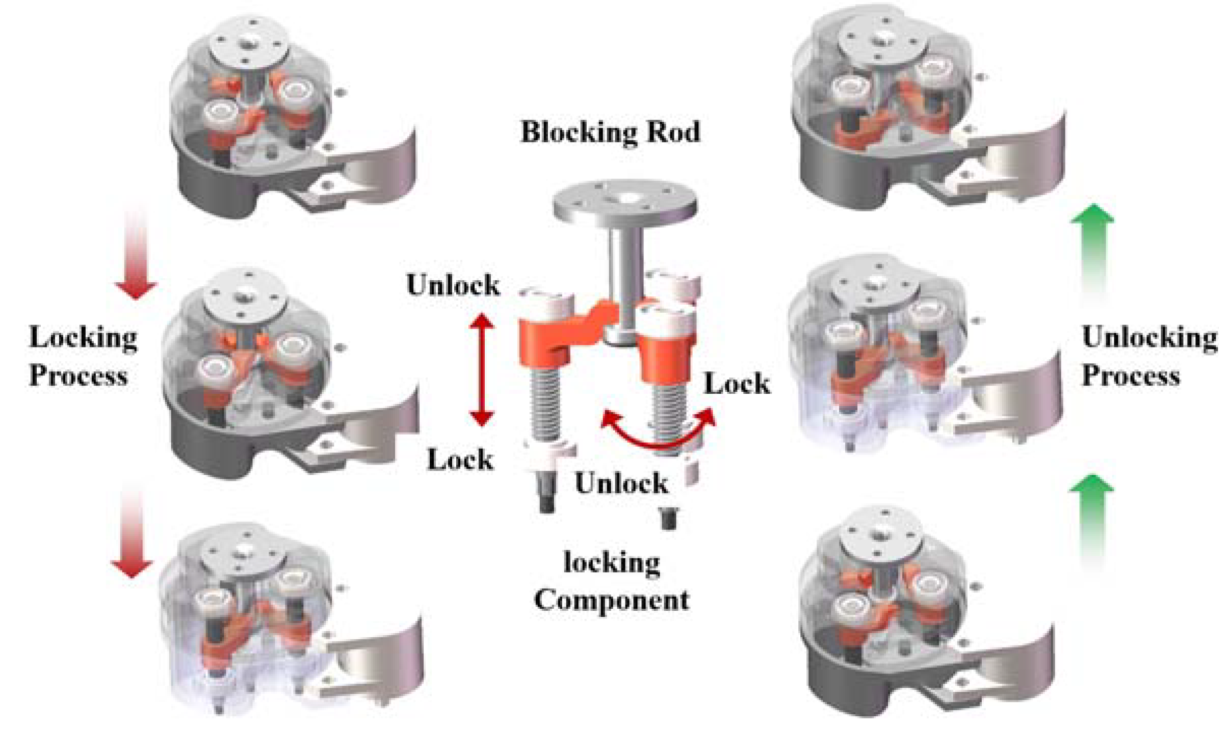
The specific working process of the locking component is shown in Figure 4. The locking rod and other locking components are respectively installed on two docking surfaces, which are the ORU surface and the cabin surface.
Orientation stage: The locking claw of the locking component is in an ‘open’ state, waiting for the locking rod to be in place. After the two docking surfaces reach the predetermined position, the guidance phase ends, and the locking rod reaches the position where it can be captured.
Locking stage: After the locking rod is in place, the driving source drives the gear to rotate. The gear drives the thread rod to rotate. Under the action of friction, the screw rod drives the locking claw to rotate. The locking claw grasps the locking rod. As the gear continues to rotate, due to the stop effect of the locking rod, the locking claw moves downward along the thread. The locking rod moves downward under the action of pressing force, and the two docking surfaces continue to approach, and finally the docking locking is achieved.
The unlocking stage is the reverse of the above process.
3. Strength Check and Optimization of Locking Components
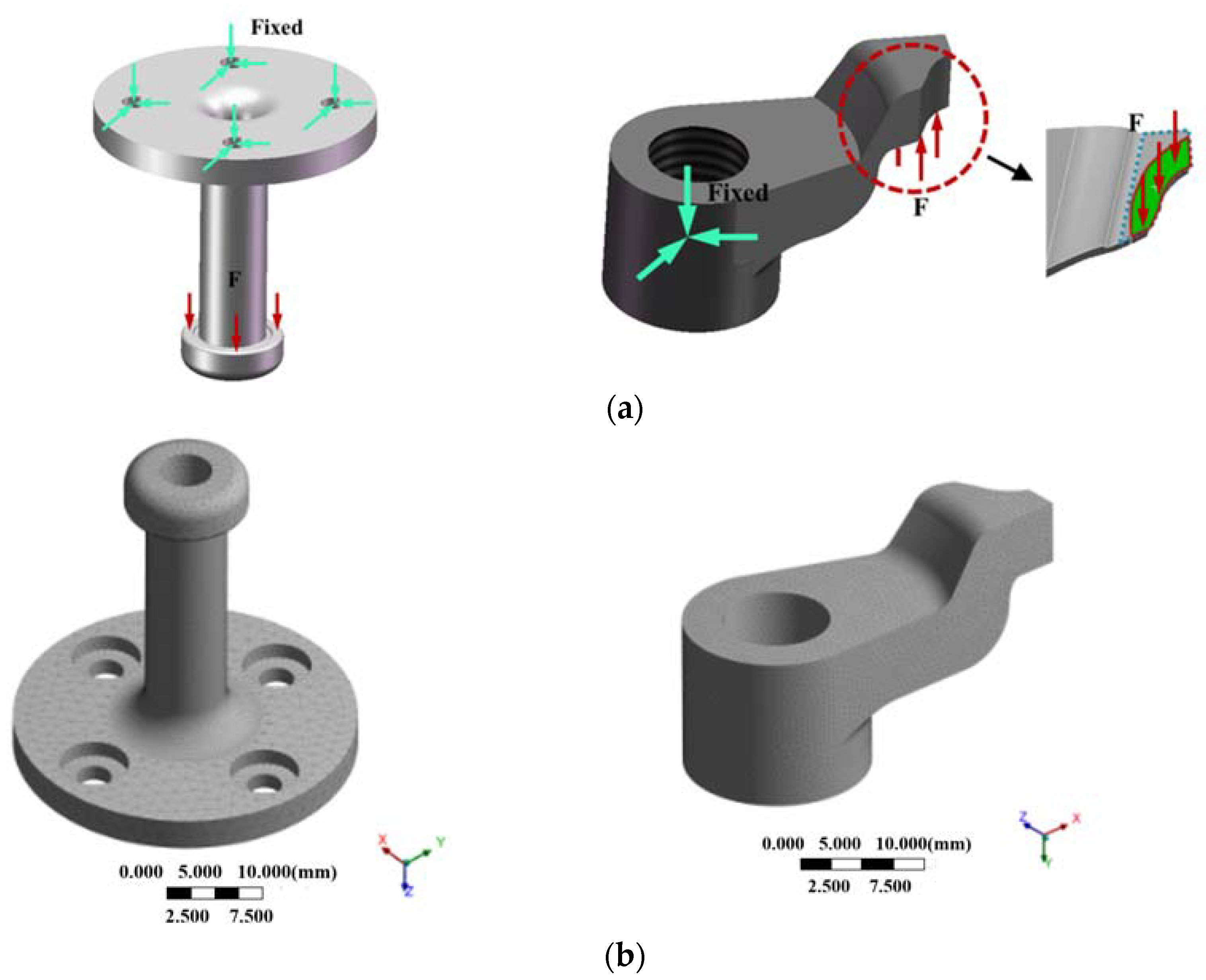
The design of the locking rod and locking claw is verified by simulation, in order to meet the locking force of 5000 N. The boundary conditions and the mesh of the locking rod and the locking claw are shown in Figure 5. Fixed constraints are added to the bottom of the locking rod. A 5000 N axial force is applied to the head of the locking rod. A 200 mesh is used for mesh the locking rod and locking claw. The number of grid nodes after division are 406,237 and 214,036, respectively. The locking rod is made of titanium alloy, in order to improve the reliability of the locking rod structure. The specific material properties are shown in Table 1.
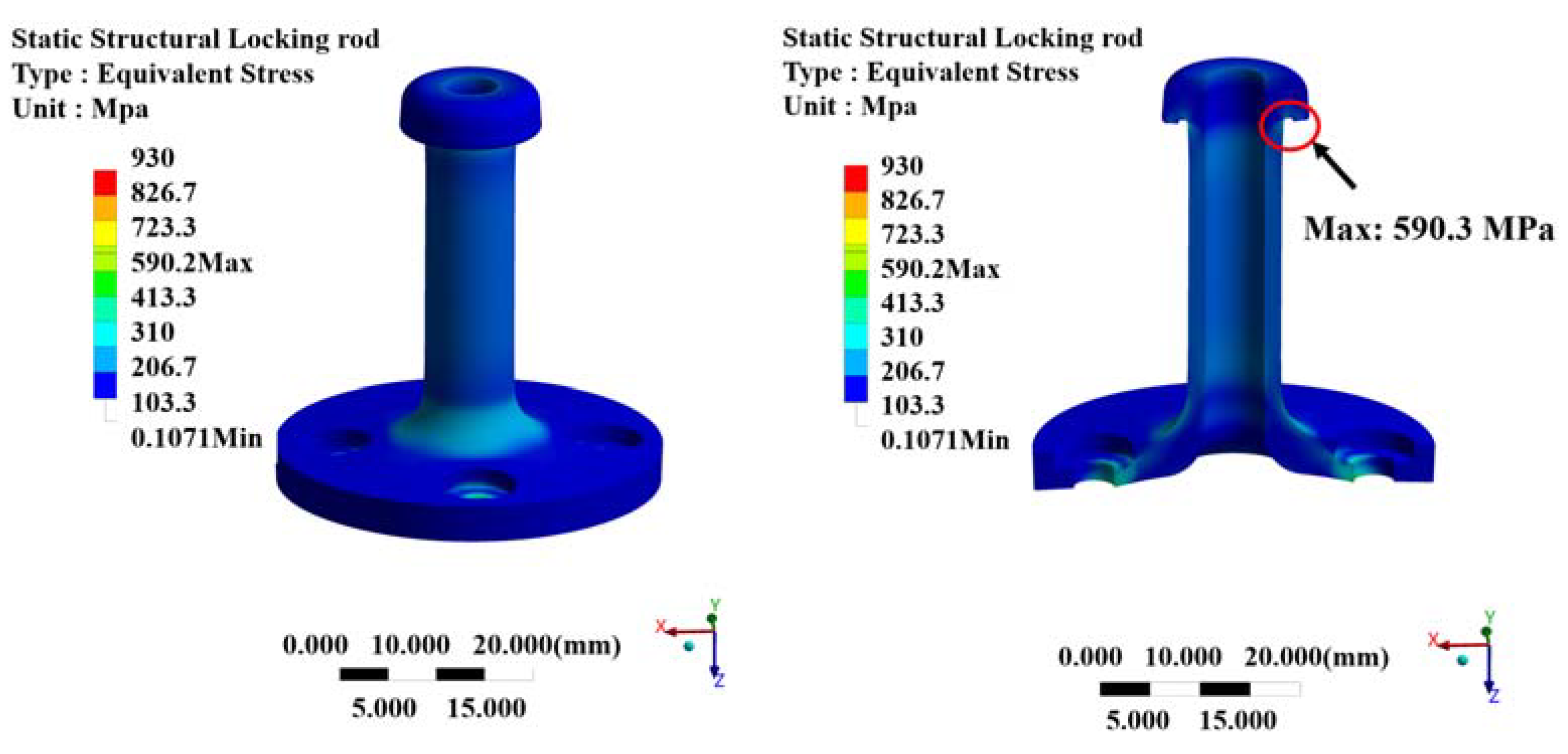
The Mises stress distribution of the locking rod is shown in Figure 6. It can be found that the maximum stress on the locking rod is 590.2 MPa, which appears at the head of the locking rod. The maximum stress of the locking rod is less than the yield criterion of titanium alloy, and the design of the locking rod has a certain strength margin.
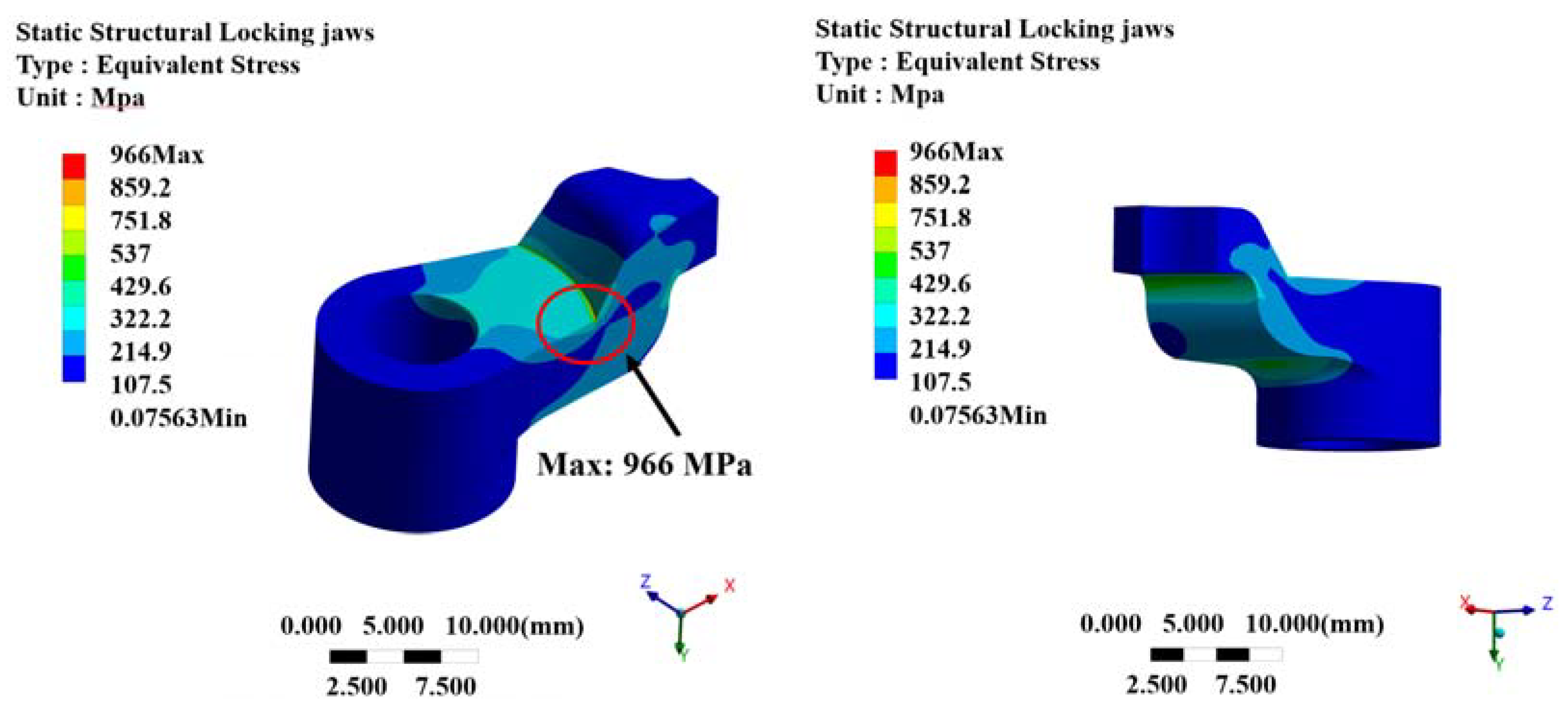
The locking claw is strength checked because it is the main force structure. The fixed constraint is applied to the transmission screw hole to meet the boundary conditions of the locking claw in the fully locked state, as shown in Figure 5a. The strength analysis results in this state are shown in Figure 7. The maximum stress of the locking claw is 966.6 MPa. The stress exceeds the yield stress of titanium alloy. Therefore, the structure does not meet the design requirements.
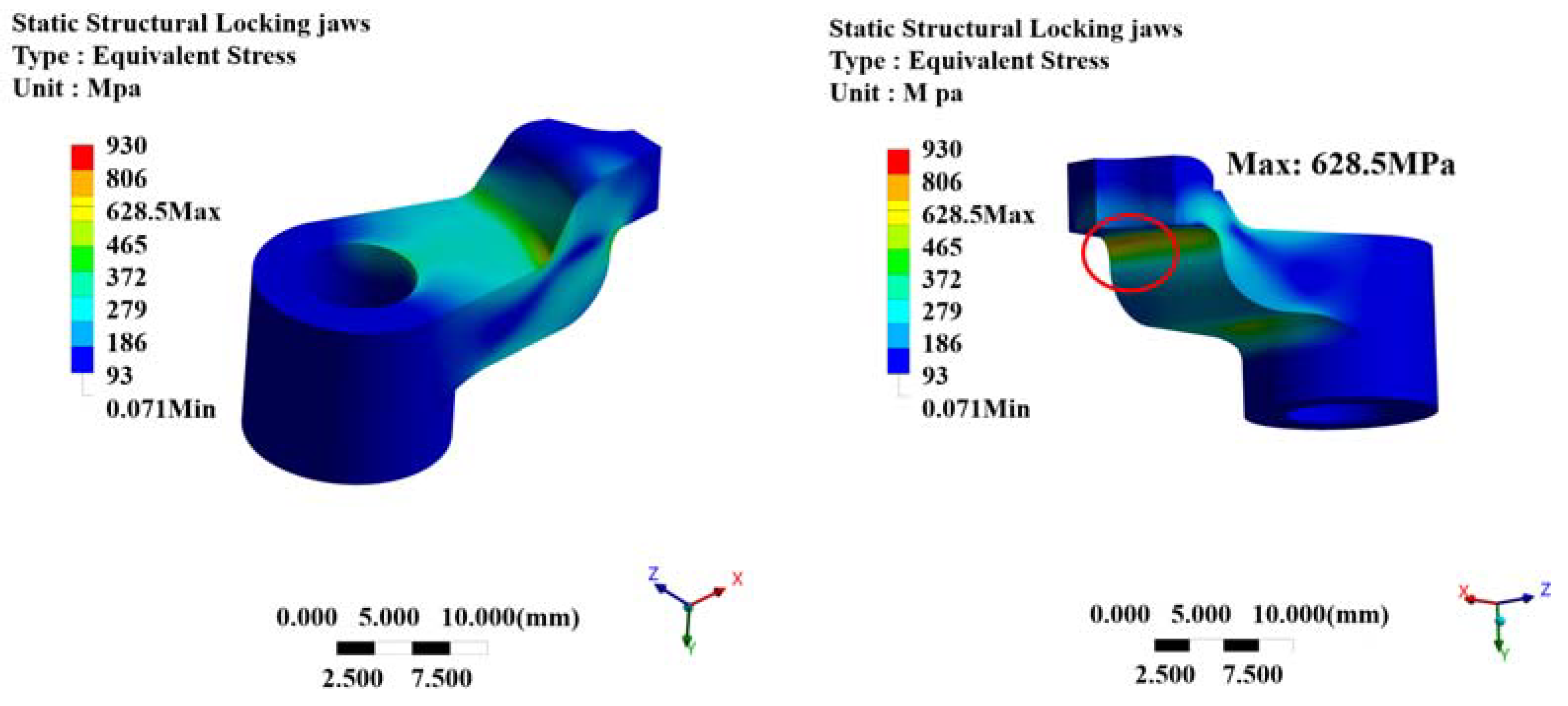
Through finite element analysis, it is found that stress concentration occurs in the locking claw. The maximum stress of the locking claw is at the L-shaped bend. The load is applied to the whole plane of the blue dotted line in Figure 5a. Through further analysis of the model, it is found that the bearing surface of the locking claw is only the green area in Figure 5a. Therefore, the L-shaped bend is changed to a U-shaped bend. The finite element calculation is carried out again, and the results are shown in Figure 8. The maximum stress of the optimized locking claw is 628.5 MPa, which is less than the yield stress of titanium alloy. Therefore, the optimized locking claw meets the strength design requirements.
4. Analysis of the Influencing Factors of the Guiding Process
4.1. Gap between the Guide Rod and the Guide Hole
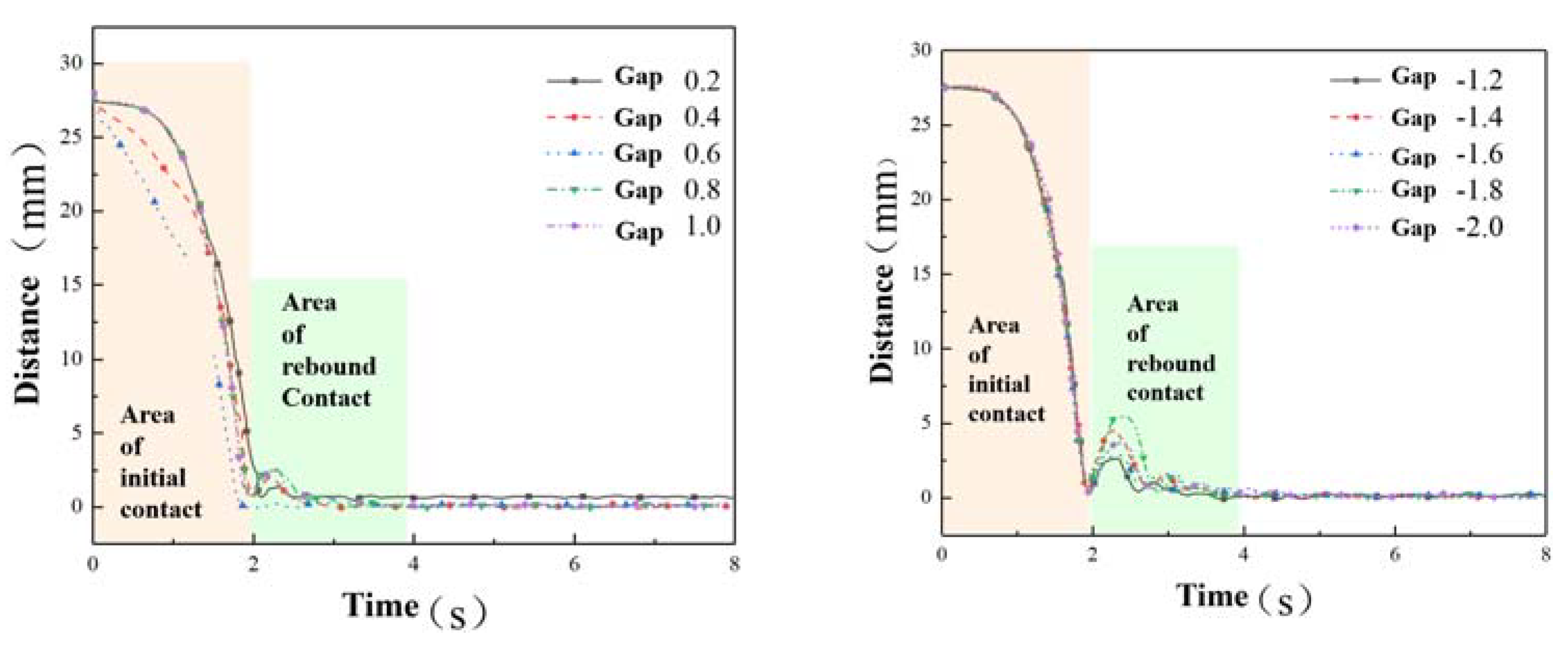
During the guiding process, the guide rod and the guide hole may be stuck. The gap between the guiding rod and the guiding hole is one main factor affecting the guiding insertion process. The smoothness between the guiding surface and the guiding rod is another main factor affecting the guiding insertion process. In order to ensure the smooth insertion of the mechanism, this section explores the influence of the gap between the guide rod and the guide hole on the guiding process, and the influence of the friction coefficient between the guiding surface and the guiding rod on the guiding process. The final parameters of the docking guidance mechanism are analyzed only from a qualitative perspective. The different gaps between the guide rod and the guide hole are set as analysis groups, as shown in Table 2. The diameter of the guide rod is 6.0 mm, and the case of no gap between the guide rod and the guide hole is not considered. Taking the first set of dimensions as an example, the size of the guide rod is 6.0 mm, and the nominal guide hole is 6.2 mm.
Assuming that there is an initial pitch angle of 1° between the two docking surfaces, the change in the spatial distance between the two docking surfaces is shown in Figure 9. The process of the first drop of the curve to the minimum value is divided into the first guiding contact area and the rebound guiding contact area. The maximum springback distance in the springback guide contact area is extracted, as shown in Figure 10. It can be found that with the increase of the gap between the guide rod and the guide hole, the maximum rebound distance of the two docking surfaces gradually increases. The increase in the rebound distance indicates that the constraint capacity between the hole and the rod decreases. The radial and axial movement between the hole and the rod occurs readily, which makes the docking process unstable.
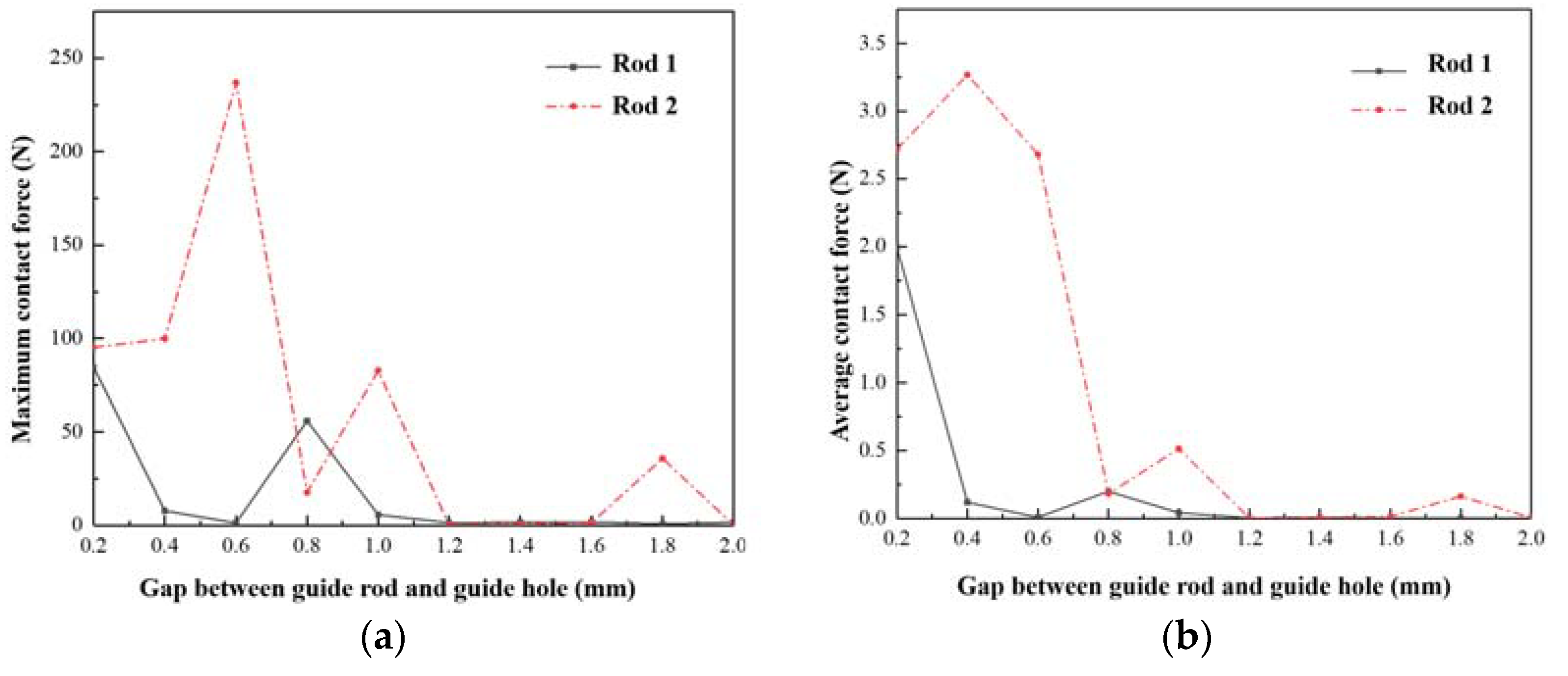
As shown in Figure 9, the influence of the gap between the hole and the rod on the guiding result can be reflected by the initial guiding area. The collision force between the two guide rods and the guide hole in the primary guide zone is extracted. The average and maximum values of the collision force between the two guide rods and the guide hole are obtained, as shown in Figure 11.
It can be found from Figure 11 that with the gradual increase of the gap, the maximum contact force and the average contact force between the guide rod and the guide hole show a downward trend. The larger contact 2 between the two contact forces is taken as the research object. When the gap between the guide rod and the guide hole is 0.4 mm, the average contact force peaks. When the gap between the guide rod and the guide hole is 0.6 mm, the maximum contact force peaks. When the gap value is greater than or equal to 0.8 mm, the maximum contact force and the average contact force fluctuate gradually. When the gap is too large, the guidance accuracy is low. The influence of the maximum contact force, the average contact force and the maximum rebound distance is considered. Finally, 0.8 mm is selected as the gap value between the guide rod and the guide hole.
4.2. Friction Coefficient between the Guide Rod and the Guide Cone
In the guidance process, the friction between the guide rod and the guide hole will affect the dynamic response of the whole docking process. When the guiding clearance is 0.8 mm, the influence of the friction coefficient between the guiding rod and the guiding hole on the guiding process is studied. The configuration of the friction coefficient between the guide rod and the guide hole is shown in Table 3.
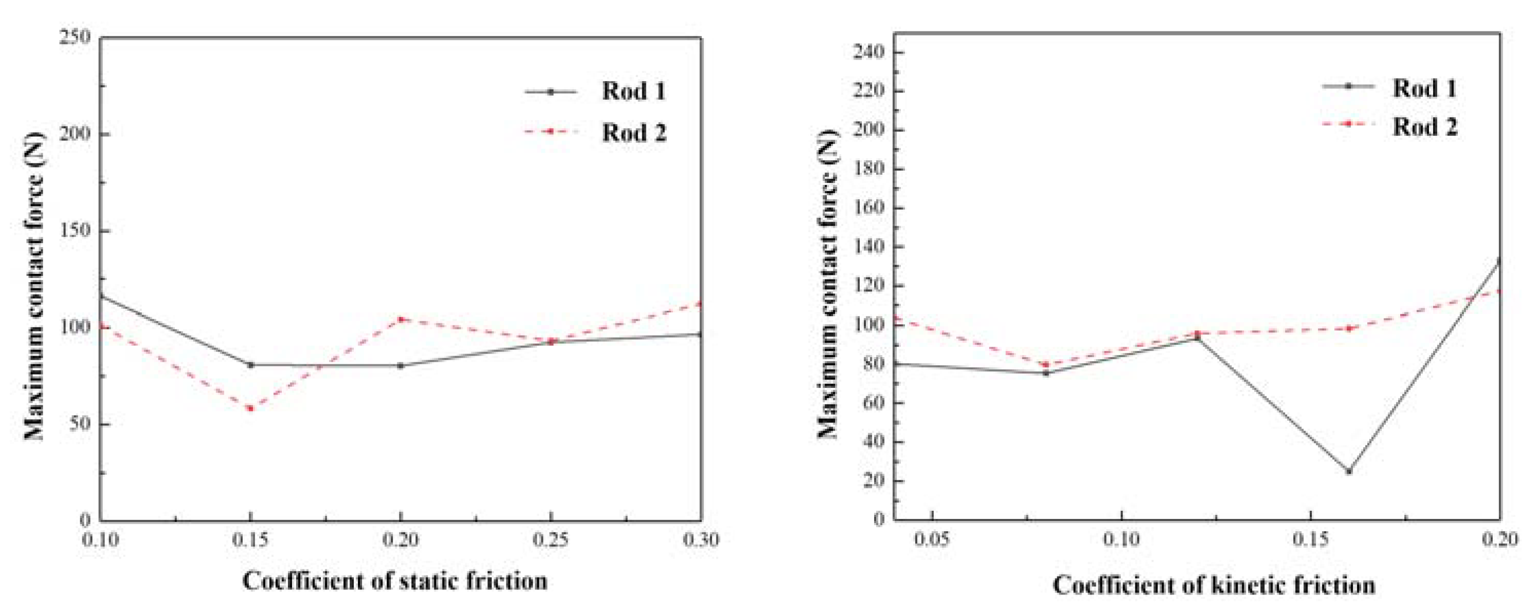
The influence of the static friction coefficient and dynamic friction coefficient on the maximum contact force in the guiding process is shown in Figure 12.
Due to the initial 1° pitch deviation between the docking surfaces, the maximum contact force between the two guide rods and the guide hole is different. The contact 2 with larger contact force is taken as the research object. It can be seen from the figure that with an increase in the static friction coefficient and the dynamic friction coefficient, the maximum contact force has an upward trend. The maximum contact force can directly reflect the thrust effect of the guide hole on the guide rod. The greater the maximum contact force, the greater the thrust effect, and the more likely the guide rod is to become stuck. In order to avoid the jamming of the double rod guide, it is necessary to effectively reduce the friction coefficient between the guide rod and the guide hole. The static friction coefficient should be less than 0.18 and the dynamic friction coefficient should be less than 0.12.
4.3. Analysis of the Influence of Effective Locking Points on the Locking Process
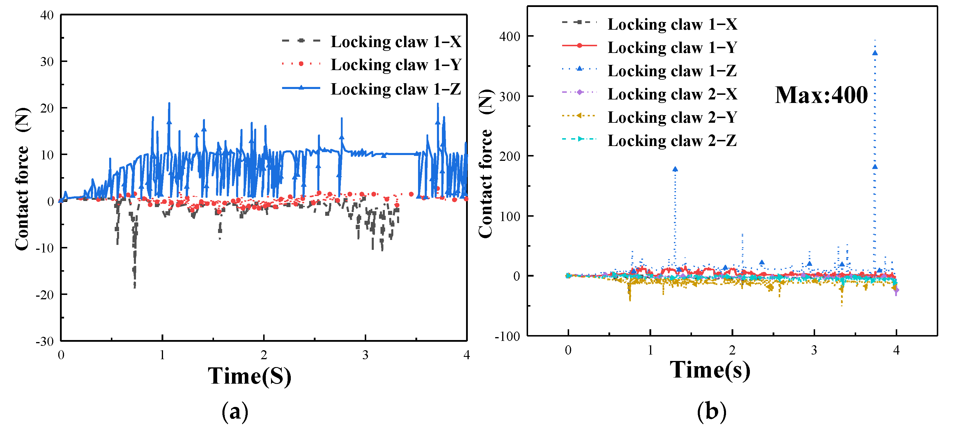
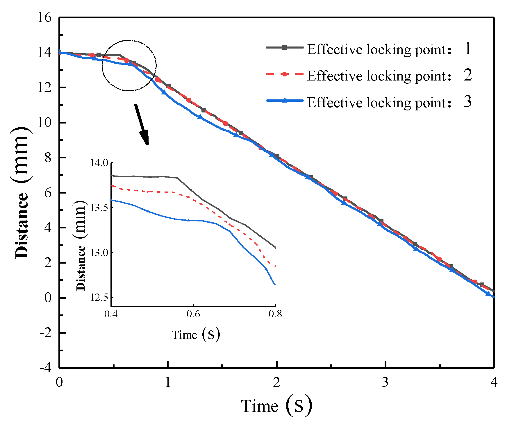
There are three locking claws of the locking component. Ideally, the three locking claws are driven synchronously by gears. Under the limit condition, a decrease in the number of locking points will lead to a deviation of the axial locking force during the locking process. In order to verify the locking reliability of the locking component, the simulation analysis of its extreme working conditions is carried out, as shown in Figure 13. The friction coefficient of the contact between the locking component and the guiding component is applied according to the f3 group in Table 3. The locking process is simulated under different effective locking points. The contact between the locking claw and the locking rod is shown in Figure 13. In the locking process, no matter how many locking points there are, the contact force of the locking claw is less than the locking force, so there is no possibility of a stuck situation.
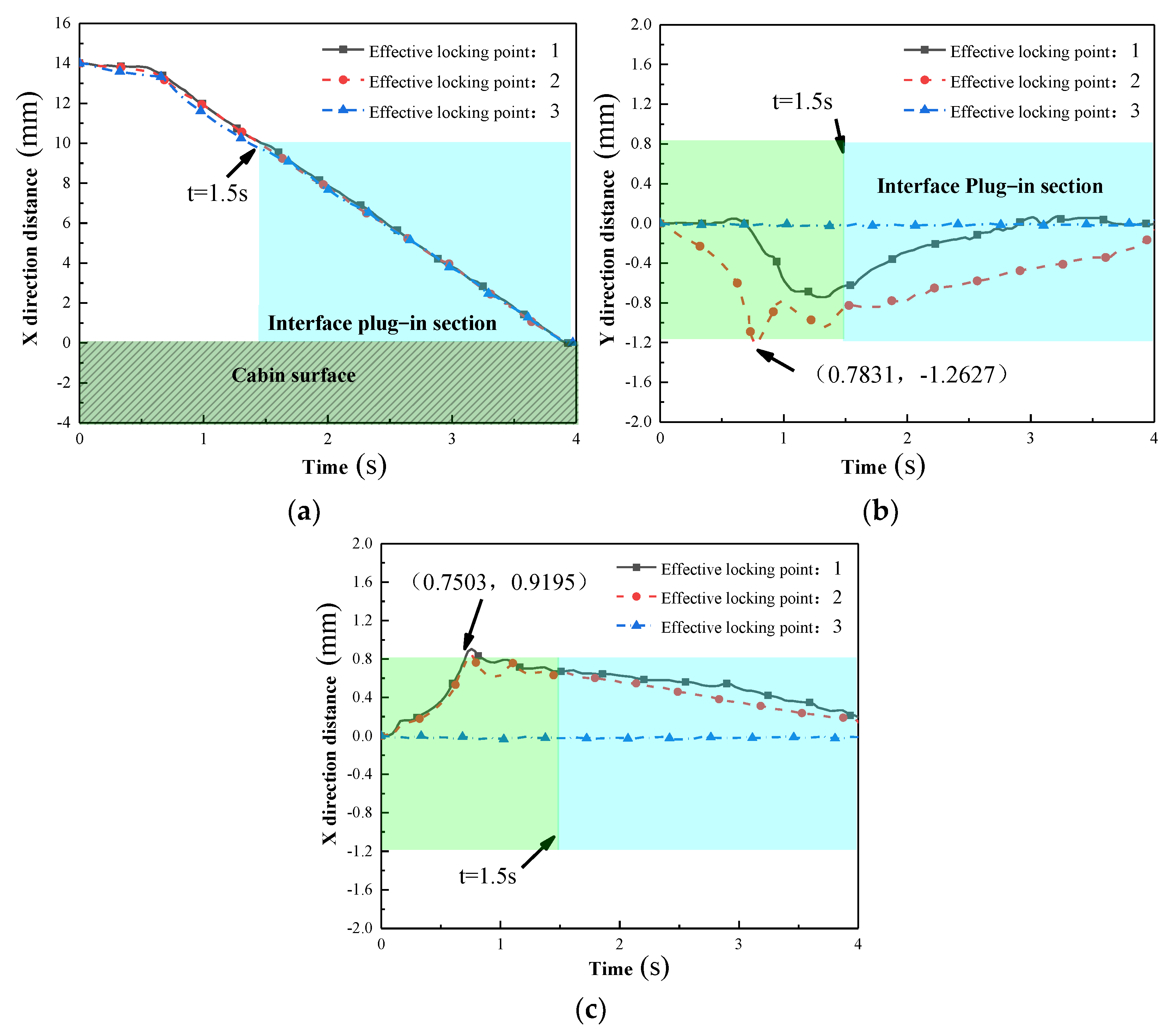
During the locking process, the change in the linear distance between the two docking surfaces is shown in Figure 14. The locking process is different under different numbers of locking points. The changes in the x, y, z three-way distances are extracted, as shown in Figure 15. As the docking process progresses, the axial distance (x direction) between the two docking surfaces gradually decreases. When the axial distance between the two docking surfaces is reduced to 10 mm, other connectors begin to plug (taking the electrical connector as an example). As shown in Figure 15a, the trianglular area in the figure is the area where the electrical connector is plugged in. The triangular region is mapped to the distance change map in the y and z directions. The radial (y, z direction) insertion tolerance of the electrical connector is generally ± 1.0 mm, as shown in Figure 15b,c. As shown in Figure 15a, in the case of different effective locking points, with the locking of the locking claw, the axial (x direction) between the two marker points reaches the minimum value of 0 mm. That is, the docking process has not been stuck, and the locking component can work normally. As shown in Figure 15b,c, when the number of effective locking points is 2 or 1, the locking component has a large swing in the y and z directions during the locking process. When the x-direction (docking axial) distance enters the range of the electrical connector, the maximum offsets in the y-direction and z-direction are within the tolerance envelope range of the electrical connector under the action of the guiding module. That is, the y direction and the z direction have been successfully corrected to the range of electrical connector insertion tolerance. As shown in Figure 14, the linear distance between the two markers is finally equal to 0, that is, the positioning and locking of the two docking surfaces are achieved under the combined action of the guiding component and the locking component. In summary, when the number of effective locking points is 3, 2 or 1, the locking component can realize the guidance and docking of the two sides. In order to ensure the stability of the docking locking process, the three locking claws of the locking module should be assured to achieve effective locking as much as possible.
4.4. Analysis of the Influence of the Smoothness of the Locking Rod on the Module Locking Process
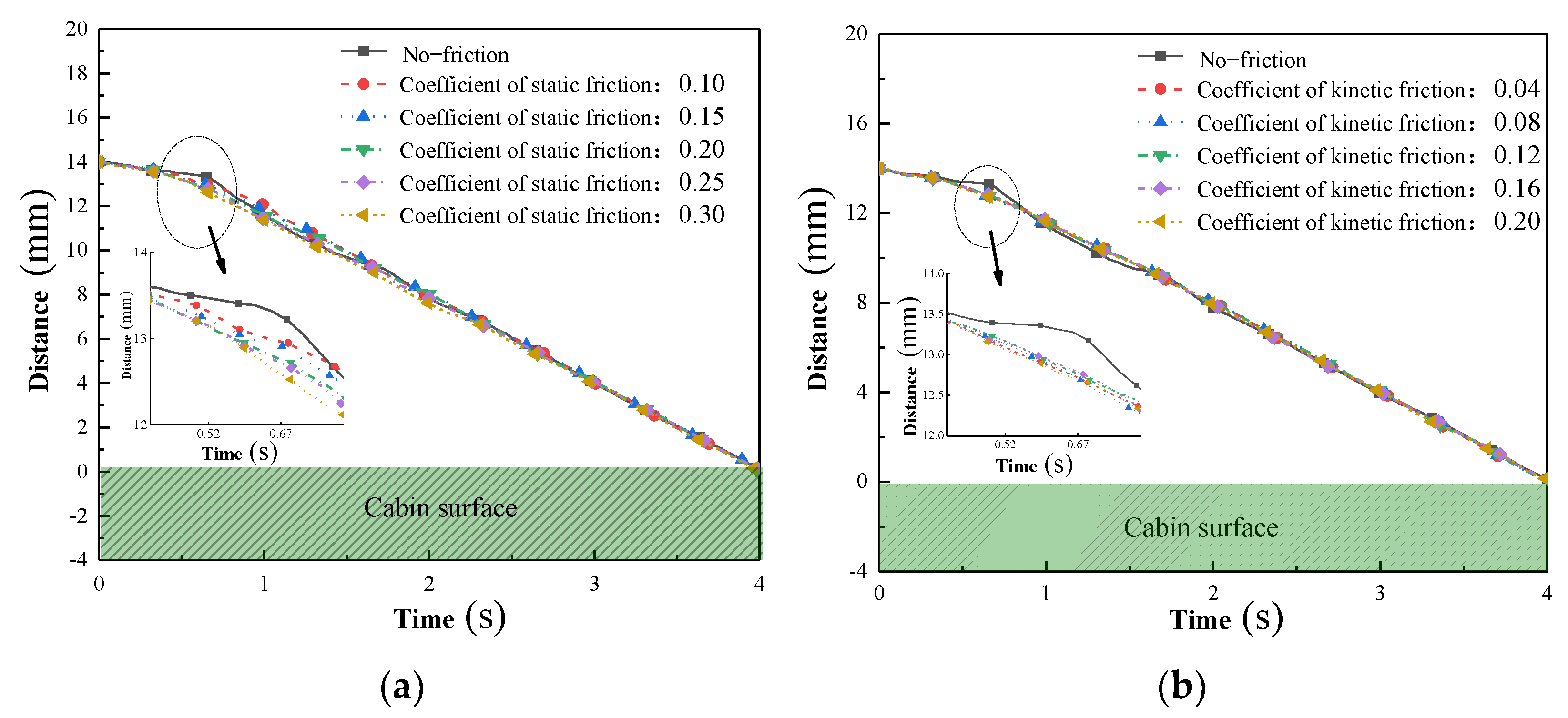
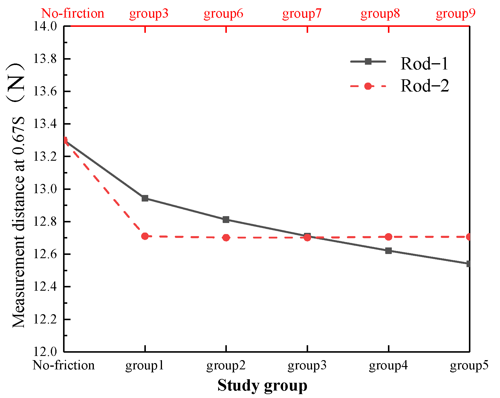
There is friction between the locking rod and the locking claw during the locking process (straight line drawing process). In order to study the influence of the friction on the locking process, the dynamic characteristics of the locking process under different friction coefficients are analyzed. The locking process is analyzed on the basis of a guiding gap of 0.8 mm. It is assumed that all three locking claws are effective locking points of the locking module. The friction coefficient between the locking claw and the locking rod is taken as the variable. The force of the three locking claws and the distance between the two docking surfaces were studied. The influence of the smoothness between the locking claw and the locking rod on the locking process in the locking module is studied. The configuration of the friction coefficient between the locking rod and the locking claw is shown in Table 4.
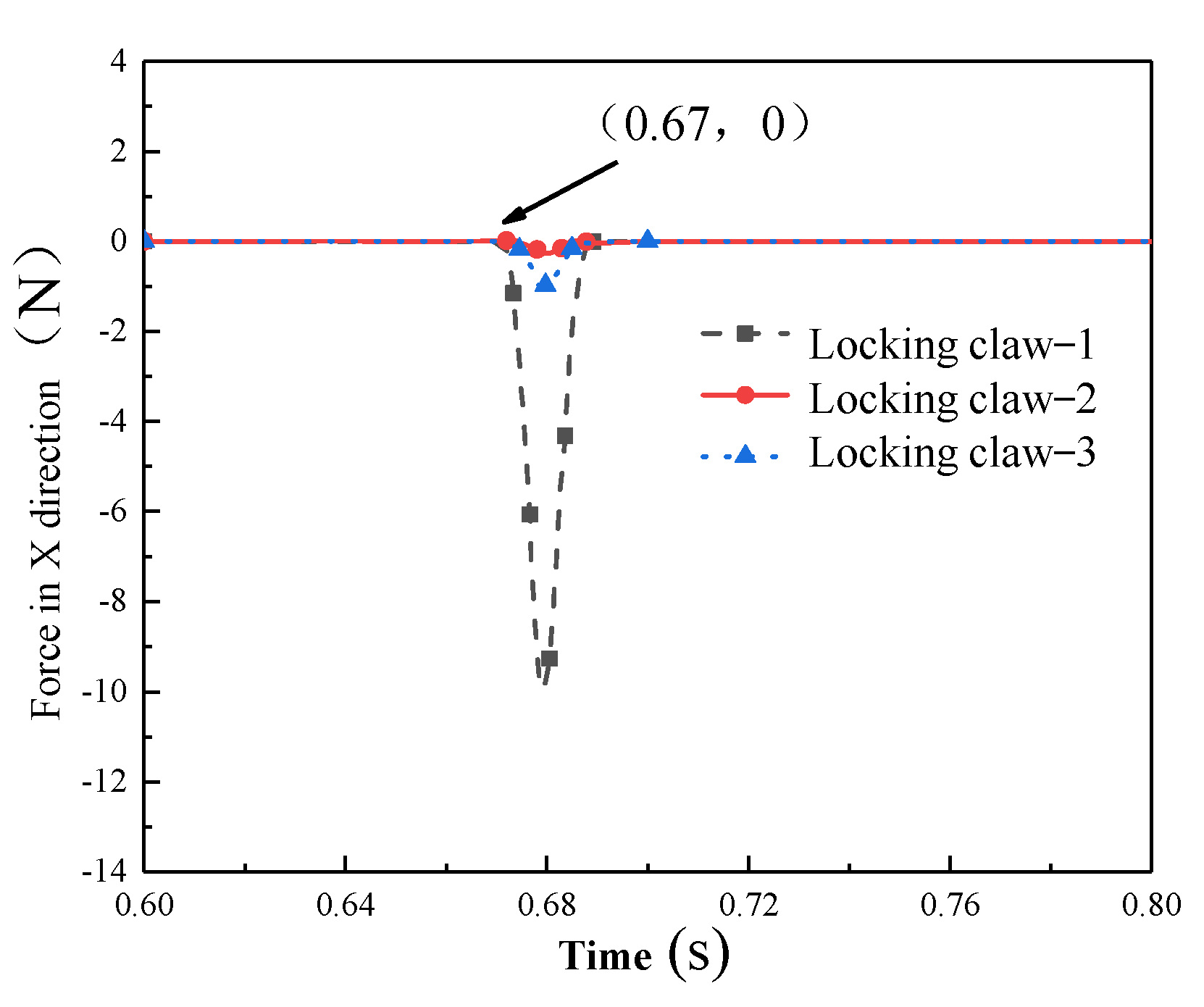
The change in the straight-line distance between the two docking surfaces is shown in Figure 16. The static friction coefficient study group and the dynamic friction coefficient study group were added without friction. It can be found that at 0.67 s, the friction-free control group produced an inflection point. At 0.67 s, the contact force curve of the locking claw and the locking rod head is extracted, as shown in Figure 17. The inflection point is caused by the collision between the locking claw and the locking rod head. The velocity direction between the docking surfaces changes abruptly. With the increase in friction coefficient, the displacement inflection point in Figure 16 gradually becomes gentler, which is mainly reflected in the influence of the static friction coefficient. The distance between the interface marker points at 0.67 s under different friction coefficient groups is extracted, as shown in Figure 18. Due to the friction between the locking claw and the locking rod, the collision between the locking claw and the locking rod head is gradually offset. The distance between the docking surfaces decreases gradually after the collision. In summary, the friction between the locking claw and the locking rod of the locking module contributes to the stability of the locking process. When the locking driving force is allowed, the locking process is more stable as the friction coefficient between the two increases. Therefore, the friction coefficient between the locking claw and the locking screw should be avoided.
5. Lock Component Function Verification
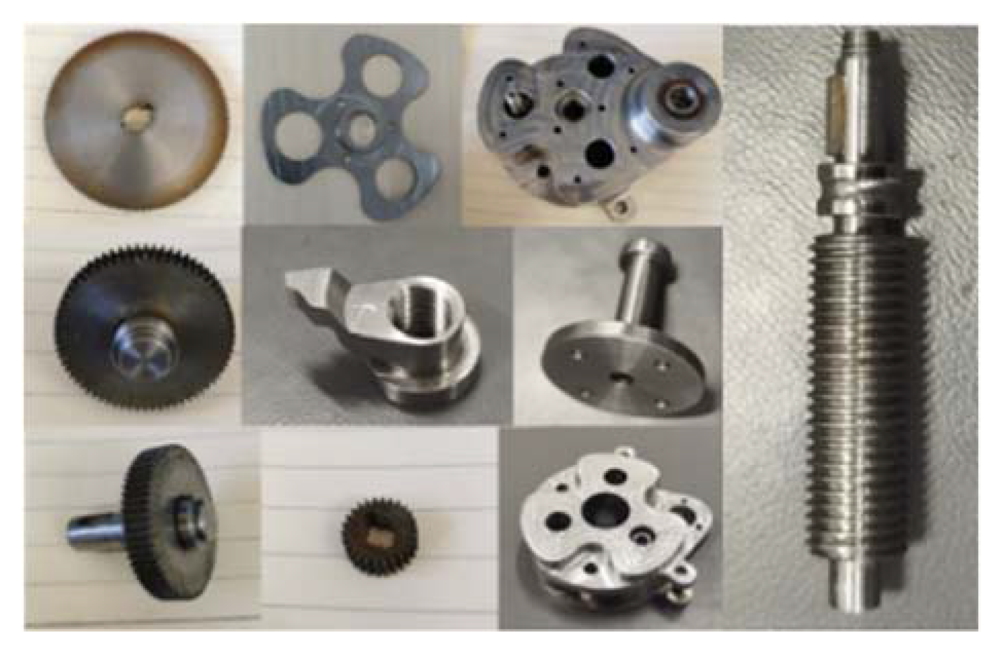
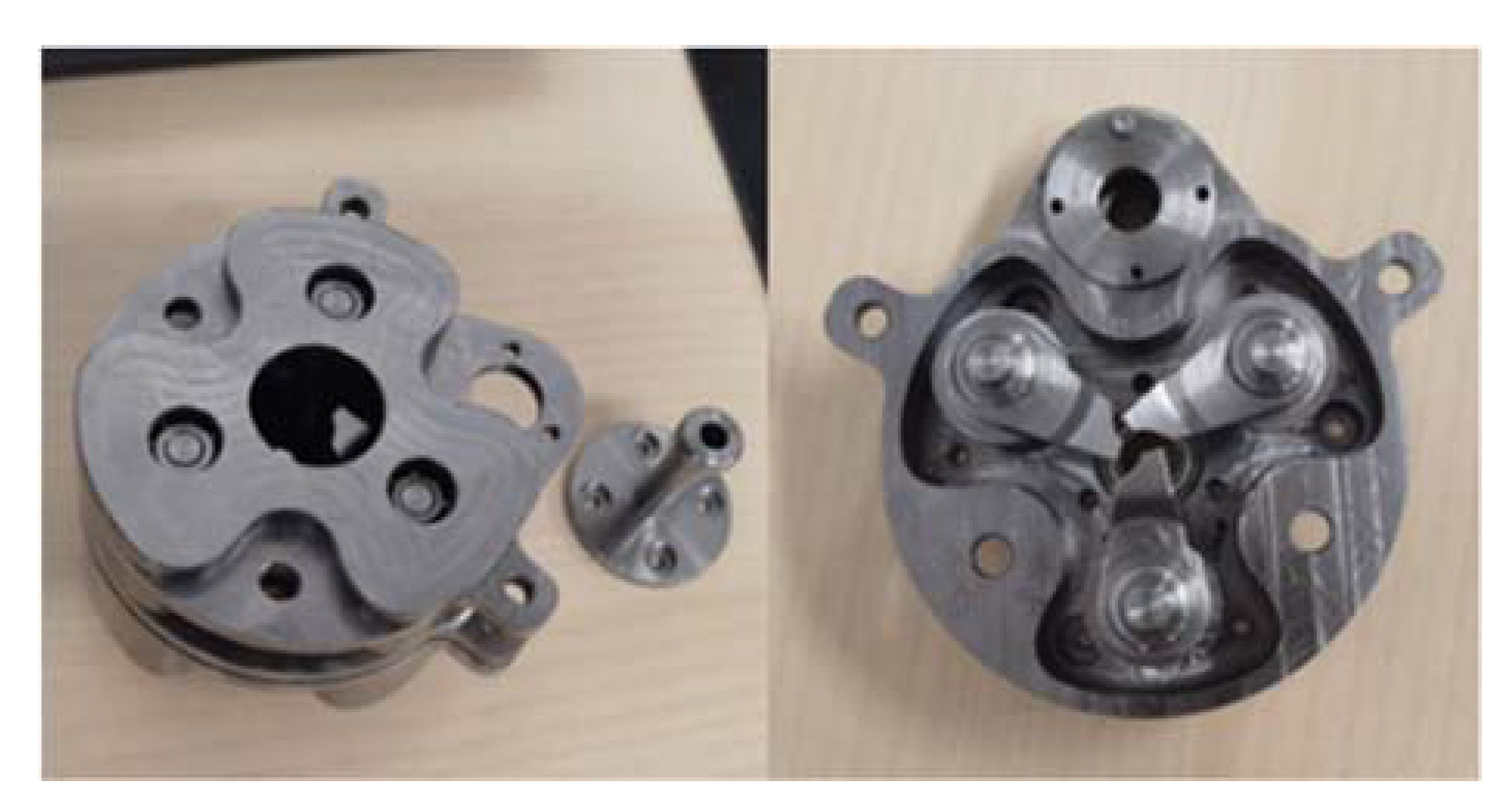
The linkage locking component is manufactured. The prototype parts are shown in Figure 19: locking rod, locking claw, transmission rod, central shaft, upper bearing, lower bearing, bearing end cover, gear a, gear b and gear c. The assembly is shown in Figure 20.
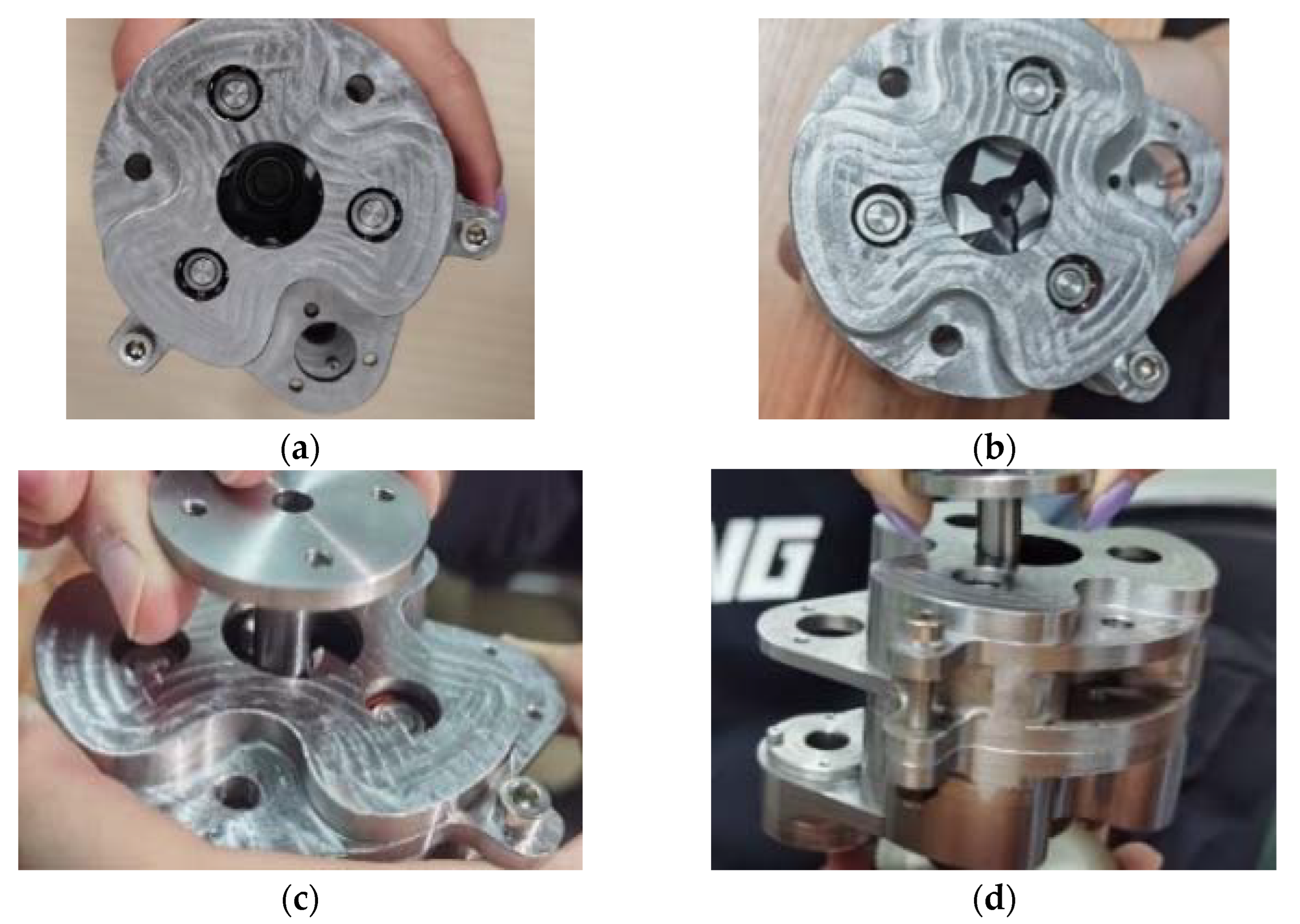
In the early stage of docking, the locking claw is open. Three locking claws open and wait for docking, as shown in Figure 21a. When the locking rod reaches the specified position, the locking claw is driven to a closed state, as shown in Figure 21b. At this time, the locking claw grasps the locking rod, as shown in Figure 21c. The locking claw continues to be driven, and the locking claw grasps the locking rod to move downward, and finally completes the locking. After the locking is completed, the linkage locking structure is tested. After testing, the locking reliability of the linkage locking mechanism was found, as shown in Figure 21d.
6. Conclusions
The linkage-type docking interface scheme has a compact mechanism, takes up little space, and can independently realize the function of axially pulling closer and locking. This scheme has many locking points and good locking rigidity.
- (1)
- Through the design of the mechanism, finite element simulation analysis and prototype processing, the conclusions are as follows: Each part of the linkage docking interface is designed in detail, through the analysis method, three-dimensional transformation method, mechanism design requirements and so on. It provides a reference for the subsequent design of space locking mechanisms with different design requirements.
- (2)
- The linkage docking interface is simulated and analyzed using ABAQUS finite element software. The results show that when the device bears the maximum axial tensile load, the locking rod meets the design requirements. Stress concentration occurs in the locking claw. Through the optimization of the structure, the maximum stress of the locking claw is 628.5 MPa, which is much smaller than the yield strength of the material, and the strength of the device is reliable.
- (3)
- The effect of guide rod hole clearance and friction coefficient on the guiding process was analyzed using ADAMS software. The effect of the number of effective points and the friction coefficient of the locking lever and locking pawl on the locking process is analyzed. The results show that the contact force in the guiding process is small when the clearance of the locking rod hole is 0.8 mm. When the friction coefficient between the locking rod and the hole is small, it is beneficial to the guiding process. When the effective points of the locking claw pulling the locking rod are 1 and 2, the locking process can be completed. When the friction force between the locking rod and the locking claw is large, it is beneficial to the locking process.
- (4)
- Linkage locking components are processed and assembled, and the principle is verified. The verification results show that the designed linkage locking assembly can meet the function of axially drawing and locking. The research results of this paper can provide design reference and theoretical guidance for the development of repeatable locking mechanisms of small space docking structures in the future.
Author Contributions
Conceptualization, Z.N., J.Z. and N.K.; methodology, J.R. and J.Z.; software, J.R. and Z.N.; validation, Z.N., R.H. and Y.Z.; formal analysis, B.W.; investigation, B.W. and Y.Z.; resources, N.K.; data curation, Z.N.; writing—original draft preparation, J.R. and Z.N.; writing—review and editing, Z.N. and N.K.; visualization, J.Z.; supervision, N.K.; project administration, N.K.; funding acquisition, N.K. All authors have read and agreed to the published version of the manuscript.
Funding
National Key R&D Program of China (2022YFB3402800).
Conflicts of Interest
The authors declare no conflict of interest.
References
- Daniele, C.; Marco, C. Design and Testing of Torveastro: An Outer Space Service Robot. Appl. Sci. 2023, 13, 1187. [Google Scholar]
- Flores-Abad, A.; Ma, O.; Pham, K.; Ulrich, S. A review of space robotics technologies for on-orbit servicing. Prog. Aerosp. Sci. 2014, 68, 1–26. [Google Scholar] [CrossRef]
- Pinson, R.; Howard, R.; Heaton, A. Orbital Express advanced video guidance sensor: Ground testing, flight results and comparisons. In Proceedings of the AIAA Guidance, Navigation and Control Conference and Exhibit, Honolulu, HI, USA, 18–21 August 2008; pp. 1–12. [Google Scholar]
- Zhai, X.; Li, X.H.; Zhou, S.Y. Structure design and analysis for the spacecraft On-Orbit Replacement Unit (ORU). Appl. Mech. Mater. 2013, 437, 449–453. [Google Scholar] [CrossRef]
- Kortmann, M.; Zeis, C.; Meinert, T.; Dueck, A.; Schroder, K.U. Design and qualification of a multifunctional interface for modular satellite systems. In Proceedings of the 69th International Astronautical Congress, Bremen, Germany, 1–5 October 2018; pp. 1–8. [Google Scholar]
- Jankovic, M.; Brinkmann, W.; Bartsch, S.; Palazzetti, R.; Yan, X.T. Concepts of active payload modules and end-effectors suitable for Standard Interface for Robotic Manipulation of Payloads in Future Space Missions (SIROM) interface. In Proceedings of the 2018 IEEE Aerospace Conference, Bremen, Germany, 1–5 October 2018; pp. 1–15. [Google Scholar]
- Wang, W.L.; Yang, J.Z. Spacecraft Docking & Capture Technology: Review. J. Mech. Eng. 2021, 57, 215–231. [Google Scholar]
- Ogilvie, A.; Allport, J.; Hannah, M.; Lymer, J. Autonomous robotic operations for on-orbit satellite servicing. Proc. SPIE Int. Soc. Opt. Eng. 2008, 6958, 1–12. [Google Scholar]
- Rossetti, D.; Keer, B.; Panek, J.; Ritter, B.; Reed, B.; Cepollina, F. Spacecraft modularity for serviceable satellites. In Proceedings of the AIAA SPACE 2014 Conference and Exposition, Pasadena, CA, USA, 5–9 May 2015; pp. 1–12. [Google Scholar]
- Fanti, L.; Pimpinelli, S. HP1: A functionally multifaceted protein. Curr. Opin. Genet. Dev. 2008, 18, 169–174. [Google Scholar] [CrossRef]
- Medina, A.; Tomassini, A.; Suatoni, M.; Aviles, M.; Solway, N.; Coxhill, I.; Paraskevas, I.S.; Rekleitis, G.; Papadopoulos, E.; Krenn, R.; et al. Towards a standardized grasping and refuelling on-orbit servicing for geo spacecraft. Acta Astronaut. 2017, 134, 1–10. [Google Scholar] [CrossRef]
- Yamagishi, A.; Kawaguchi, Y.; Hashimoto, H.; Yano, H.; Imai, E.; Kodaira, S.; Uchihori, Y.; Nakagawa, K. Environmental data and survival data of Deinococcus aetherius from the exposure facility of the Japan experimental module of the international space station obtained by the Tanpopo mission. Astrobiology 2018, 18, 1369–1374. [Google Scholar] [CrossRef]
- Olivieri, L.; Francesconi, A. Design and test of a semiandrogynous docking mechanism for small satellites. Acta Astronaut. 2016, 122, 219–230. [Google Scholar] [CrossRef]
- Zhang, W.; Li, F.; Li, J. Review of on-orbit robotic arm active debris capture removal methods. Aerospace 2023, 10, 13. [Google Scholar] [CrossRef]
- Piotr, P.; Karol, S. Impedance control using selected compliant prismatic joint in a free-floating space manipulator. Aerospace 2022, 9, 406. [Google Scholar]
- Ge, W.M.; Lei, Y.L.; Wang, X.F.; Zhang, H.J. A novel self-reconfigurable modular robot (M2SBot): Docking mechanism design and its kinematic analysis. Appl. Mech. Mater. 2013, 392, 281–284. [Google Scholar] [CrossRef]
- Tang, S.; Chen, B.D.; Bai, H.; Zhang, C.F.; Zhao, J.R. Innovation design of capture lock in the conical rod typed docking mechanism. J. Mach. Des. 2009, 26, 66–69. [Google Scholar]
- Davis, J.D.; Sevimli, Y.; Ackerman, M.K.; Chirikjian, G.S. A robot capable of autonomous robotic team repair: The Hex-DMR II system. Adv. Reconfigurable Mech. Robot. II 2016, 36, 619–631. [Google Scholar]
- Vedova, F.D.; Morin, P.; Roux, T. Interfacing sail modules for use with “space tugs”. Aerospace 2018, 5, 48. [Google Scholar] [CrossRef]
- Huang, Y.; Li, Q.; Chen, X.Q.; Zhao, Y. Modeling and Simulating of Independent On-orbit Servicing Spacecrafts' Docking Process. Comput. Simul. 2011, 28, 57–61. [Google Scholar]
- Qi, J.; Zhang, X.; Zhao, Y.; Huang, Y. Three-dimensional dynamic modeling and parametric analysis for quasi probe-cone soft docking used in miniature satellites. J. Vib. Shock. 2017, 36, 58–67. [Google Scholar]
- Ping, X.L.; Yang, Z.H. Design method of receiving cone taper for rod-cone typed docking mechanism. Mach. Des. Manuf. 2019, 97, 47–50. [Google Scholar]
- Hays, A.B.; Tchoryk, P., Jr.; Pavlich, J.C.; Ritter, G.A.; Wassick, G.J. Advancements in design of an autonomous satellite docking system. Proc. SPIE Int. Soc. Opt. Eng. 2004, 23, 286–299. [Google Scholar]
- Han, W.; Huang, Y.Y.; Zhang, X.; Chen, X.Q. Collision simulation analysis for flexible probe-cone docking mechanism. Aerosp. Shanghai 2012, 29, 49–53. [Google Scholar] [CrossRef]
- Christiansen, S.; Nilson, T. Docking System Mechanism Utilized on Orbital Express Program. In Proceedings of the 39th Aerospace Mechanisms Symposium, Huntsvillle, AL, USA, 7–9 May 2008; pp. 207–220. [Google Scholar]
- Hays, A.B.; Tchoryk, P., Jr.; Pavlich, J.C.; Wassick, G. Dynamic simulation and validation of a satellite docking system. Proc. SPIE-Int. Soc. Opt. Eng. 2003, 5088, 77–88. [Google Scholar]
- Boesso, A.; Francesconi, A. ARCADE small-scale docking mechanism for micro-satellites. Acta Astronaut. 2013, 86, 77–87. [Google Scholar] [CrossRef]
- Ma, R.Q.; Gao, X.Y.; Jiang, S.Q. Design and simulation analysis of small-size space docking mechanism. Manned Speaceflight 2019, 25, 783–788. [Google Scholar]
- Valle, S.C.; Urrutxua, H.; Solano-López, P. Relative dynamics and modern control strategies for rendezvous in libration point orbits. Aerospace 2022, 9, 798. [Google Scholar] [CrossRef]
- Li, X.; Wang, W.; Shi, J. Design analysis of a passive buffer system for space-assembled segmented mirrors. Appl. Sci. 2019, 9, 985. [Google Scholar] [CrossRef]
Figure 1.
Docking tolerance guide cone diameter judgment.

Figure 2.
Overall structure of the locking assembly.

Figure 3.
Internal structure of the locking assembly.

Figure 4.
The locking process of the ORU locking module.

Figure 5.
Boundary conditions and mesh for strength checks of core parts of the locking module. (a) Boundary conditions of locking rod and locking claw; (b) Figure 6 Grid of locking rod and locking claw.
Figure 5.
Boundary conditions and mesh for strength checks of core parts of the locking module. (a) Boundary conditions of locking rod and locking claw; (b) Figure 6 Grid of locking rod and locking claw.

Figure 6.
Locking rod stress distribution.

Figure 7.
Stress distribution of locking jaws before optimization.

Figure 8.
Optimized locking jaw stress distribution.

Figure 9.
Different guide bar and guide hole clearances guide process distance change.

Figure 10.
Maximum rebound distance of rebound guide area with different clearances.

Figure 11.
Maximum contact force and average contact force at different clearances. (a) Maximum contact force. (b) Average contact force.
Figure 11.
Maximum contact force and average contact force at different clearances. (a) Maximum contact force. (b) Average contact force.

Figure 12.
Effect of different friction coefficients on the maximum contact force in the initial guidance zone.
Figure 12.
Effect of different friction coefficients on the maximum contact force in the initial guidance zone.

Figure 13.
Contact force of locking jaws. (a) An effective locking point (b) Two effective locking points (c) Three effective locking points.
Figure 13.
Contact force of locking jaws. (a) An effective locking point (b) Two effective locking points (c) Three effective locking points.


Figure 14.
Spatial distance variation of locking process with different numbers of effective locking points.
Figure 14.
Spatial distance variation of locking process with different numbers of effective locking points.

Figure 15.
Variation of three-way distances during docking and locking with different numbers of effective locking points. (a) x. (b) y. (c) z.
Figure 15.
Variation of three-way distances during docking and locking with different numbers of effective locking points. (a) x. (b) y. (c) z.

Figure 16.
Effect of friction coefficient on the locking process of the locking module. (a) Coefficient of static friction. (b) Coefficient of kinetic friction.
Figure 16.
Effect of friction coefficient on the locking process of the locking module. (a) Coefficient of static friction. (b) Coefficient of kinetic friction.

Figure 17.
x-directional collision force between locking jaw and locking rod.

Figure 18.
The effect of friction coefficient on the bounce distance of locking process.

Figure 19.
Prototype parts.

Figure 20.
Prototype assembly.

Figure 21.
Working process of the prototype. (a) Locking claw open state. (b) Locking claw closed state. (c) Locking claw lock locking rod. (d) Locking claw locking test.
Figure 21.
Working process of the prototype. (a) Locking claw open state. (b) Locking claw closed state. (c) Locking claw lock locking rod. (d) Locking claw locking test.


Table 1.
Mechanical properties of components.
| Part | Elastic Modulus/GPa | Poisson Ratio | Yield Strength/MPa |
|---|---|---|---|
| Locking rod Locking claw | 960 | 0.36 | 930 |
Table 2.
Guide bar and guide hole clearance configuration.
| Group | 1 | 2 | 3 | 4 | 5 | 6 | 7 | 8 | 9 | 10 |
|---|---|---|---|---|---|---|---|---|---|---|
| Gap/mm | 0.2 | 0.4 | 0.6 | 0.8 | 1.0 | 1.2 | 1.4 | 1.6 | 1.8 | 2.0 |
Table 3.
Guide rod and guide hole friction coefficient configuration table.
| Name | Study Group1 | Study Group2 | ||||||||
|---|---|---|---|---|---|---|---|---|---|---|
| f1 | f2 | f3 | f4 | f5 | f3 | f6 | f7 | f8 | f9 | |
| Coefficient of static friction | 0.1 | 0.15 | 0.2 | 0.25 | 0.3 | 0.2 | 0.2 | 0.2 | 0.2 | 0.2 |
| Coefficient of kinetic friction | 0.04 | 0.04 | 0.04 | 0.04 | 0.04 | 0.04 | 0.08 | 0.12 | 0.16 | 0.2 |
Table 4.
Locking rod and locking claw friction coefficient configuration.
| Name | Study Group 1 | Study Group 2 | ||||||||
|---|---|---|---|---|---|---|---|---|---|---|
| f1 | f2 | f3 | f4 | f5 | f3 | f6 | f7 | f8 | f9 | |
| Coefficient of static friction | 0.1 | 0.15 | 0.2 | 0.25 | 0.3 | 0.2 | 0.2 | 0.2 | 0.2 | 0.2 |
| Coefficient of kinetic friction | 0.04 | 0.04 | 0.04 | 0.04 | 0.04 | 0.04 | 0.08 | 0.12 | 0.16 | 0.2 |
Disclaimer/Publisher’s Note: The statements, opinions and data contained in all publications are solely those of the individual author(s) and contributor(s) and not of MDPI and/or the editor(s). MDPI and/or the editor(s) disclaim responsibility for any injury to people or property resulting from any ideas, methods, instructions or products referred to in the content. |
© 2023 by the authors. Licensee MDPI, Basel, Switzerland. This article is an open access article distributed under the terms and conditions of the Creative Commons Attribution (CC BY) license (https://creativecommons.org/licenses/by/4.0/).
Share and Cite
MDPI and ACS Style
Niu, Z.; Zhang, J.; Kong, N.; Ren, J.; Zhuang, Y.; Wang, B.; Han, R. Design and Simulation Analysis of Docking Interface of Linked In-Orbit Replacement Module. Machines 2023, 11, 491. https://doi.org/10.3390/machines11040491
AMA Style
Niu Z, Zhang J, Kong N, Ren J, Zhuang Y, Wang B, Han R. Design and Simulation Analysis of Docking Interface of Linked In-Orbit Replacement Module. Machines. 2023; 11(4):491. https://doi.org/10.3390/machines11040491
Chicago/Turabian StyleNiu, Zhuangwei, Jie Zhang, Ning Kong, Jie Ren, Yuan Zhuang, Bo Wang, and Runqi Han. 2023. "Design and Simulation Analysis of Docking Interface of Linked In-Orbit Replacement Module" Machines 11, no. 4: 491. https://doi.org/10.3390/machines11040491
Note that from the first issue of 2016, this journal uses article numbers instead of page numbers. See further details here.