Review

Intelligent Fault Diagnosis of an Aircraft Fuel System Using Machine Learning—A Literature Review

Integrated Vehicle Health Management Centre, School of Aerospace, Transport, and Manufacturing, Cranfield University, Bedfordshire MK43 0AL, UK
*
Author to whom correspondence should be addressed.
Machines 2023, 11(4), 481; https://doi.org/10.3390/machines11040481
Submission received: 25 February 2023 / Revised: 31 March 2023 / Accepted: 13 April 2023 / Published: 16 April 2023

Abstract

:
The fuel system, which aims to provide sufficient fuel to the engine to maintain thrust and power, is one of the most critical systems in the aircraft. However, possible degradation modes, such as leakage and blockage, can lead to component failure, affect performance, and even cause serious accidents. As an advanced maintenance strategy, Condition Based Maintenance (CBM) can provide effective coverage, by combining state-of-the-art sensors with data acquisition and analysis techniques to guide maintenance before the asset’s degradation becomes serious. Artificial Intelligence (AI), particularly machine learning (ML), has proved effective in supporting CBM, for analyzing data and generating predictions regarding the asset’s health condition, thus influencing maintenance plans. However, from an engineering perspective, the output of ML algorithms, usually in the form of data-driven neural networks, has come into question in practice, as it can be non-intuitive and lacks the ability to provide unambiguous engineering signals to maintainers, making it difficult to trust. Engineers are interested in a deterministic decision-making process and how it is being revealed; algorithms should be able to certify and convince engineers to approve recommended actions. Explainable AI (XAI) has emerged as a potential solution, providing some of the logic on how the output is derived from the input given, which may help users understand the diagnostic result of the algorithm. In order to inspire and advise data scientists and engineers who are about to develop and use AI approaches in fuel systems, this paper explores the literature of experiment, simulation, and AI-based diagnostics for the fuel system to make an informed statement as to the progress that has been made in intelligent fault diagnostics for fuel systems, emphasizing the necessity of giving unambiguous engineering signals to maintainers, as well as highlighting potential areas for future research.

1. Introduction

1.1. Motivation

Within civil aerospace, Original Equipment Manufacturers (OEMs) and Maintenance Repair and Operation (MRO) organisations are gradually adding maintenance as a service to their portfolio, with more emphasis being placed on predicting maintenance, especially that which is not scheduled. While Condition Based Maintenance (CBM), the removal of components based on their condition, rather than the arrival of a set maintenance point in time, is some way away, it is being realised on some components. On this journey, the arrival of Integrated Vehicle Health Management (IVHM) has provided many of the capabilities necessary for this transition. Sensors, diagnostic and prognostic algorithms, along with business cases, all form part of the IVHM capability, which has developed over the last 10–15 years.
Researchers in IVHM, to optimise maintenance for stakeholders, continually scan new technologies to use all available data and analyse it in the most efficient way. To do this, the field of Artificial Intelligence (AI) has come into prominence in recent years. Although incorporating a sizeable number of different approaches, a common theme is the use of Machine Learning (ML) ‘non-transparent’ techniques, ones that are data-driven, using neural networks, and trained to give the correct output for the given input. Further, because the use of AI in this way obscures the engineering rationale behind the maintenance decision, there is a need for an extra step, of Explainable AI (XAI), to put the engineering context back into the ML decision.
To enable the above-mentioned approach, a comprehensive literature review to evaluate the work done by the research community was deemed necessary. Three typical diagnostic research methodologies: experimental work, simulation modelling, and intelligent diagnostics are reviewed in sequence.

1.2. Background

Maintenance, and the algorithms that can assist in decision-making, constitute the background of this work. Since the Industrial Revolution, maintenance has continually evolved to adapt to the increasingly complex systems it serves. In aerospace, it has developed into a service that can be sold, either by OEMs or by MROs, to airlines. Consequently, in the field of research, it has become an increasingly important subject to study. Figure 1 shows the basic evolution of maintenance through time and its transition from reactive to proactive [1,2,3]. The earliest stages of a maintenance strategy, for a machine or asset, can be traced back to a simple ‘fix it when broken’ approach. Corrective maintenance represents this repair practice, performed after the occurrence of a failure. It is the simplest, but also the most expensive, form of maintenance because of the damage caused by the failure and any ‘knock-on’ effects. To prevent failures, a routine examination was introduced, called preventive maintenance, servicing the machine at regular intervals. The Wright brothers, building their aeroplane in the early twentieth century, prompted the need for such maintenance, and so its use in aerospace began. As the aviation industry was considered a highly vulnerable and risky business [4], more efficient maintenance methods were constantly sought. Preventive maintenance gradually became more complicated by considering the characteristics and average lifespan of components [5]. As most failures in the early days of aerospace were due to mechanical or design flaws, the pace of maintenance development was slow [6], but the development of the Boeing 747 changed this situation. This aircraft represented a step jump in complexity and would therefore be far more expensive in the case of repair or accident than any previous aircraft. Reliability-centred maintenance (RCM) was developed as a disciplined methodology used to identify preventative maintenance tasks, relying on statistical data from component and system behaviour in the field. RCM is still widely used today, although there is a movement towards components being maintained based on their condition rather than a scheduled time. This is termed Condition Based Maintenance (CBM) and was first introduced for monitoring components between regular-scheduled maintenance checks. Since the beginning of the information revolution, the associated technologies of data collection, transmission, storage, and processing have seen rapid growth, enabling CBM to encompass predictive maintenance (PdM) [1,5], a method by which maintenance work can be planned much more accurately by considering the current state, and remaining lifespan, of individual components or assets [7].
As one of the most important onboard systems, the civil aircraft fuel system (AFS) not only manages the fuel that represents up to 50% of the aircraft’s weight, but also maintains engine thrust continuously throughout the flight. Other functions of the AFS include:
  • Pressure refueling
  • Defueling
  • Fuel jettison
  • CG (center of gravity) adjustment
  • Adaptation to the aerodynamic geometry, structural load, and the aircraft’s manoeuvre
  • Water management
  • Fuel measuring
In addition, AFS needs to be highly automated (to save the flight crew valuable time) and remain safe under several circumstances (such as rotor burst and electrostatic charge), which makes the fuel system a complex structure. In recent years, with the development of new energy sources, the traditional AFS has been adapted to work with battery systems, fuel cells, or accommodate new fuel types (such as biofuels, liquid hydrogen, and oxygen).
Given the importance of the AFS, the number of review articles, on fuel system maintenance methods and development, is surprisingly limited. Currently, AFS relies mainly on time-based maintenance strategies (preventive maintenance), and, to a lesser degree, on CBM. The latter is beginning to be used to replace previous maintenance methods to reduce costs and the number of failures [8]. CBM is sensitive to incipient failures, but another challenge is the possibility of intermittent failures (No Fault Find, NFF) in the fuel system [9]. The good news is that health management systems, previously not being considered at the design phase, are now beginning to receive attention [10]. For example, health management has been integrated into avionics systems to support ground crew operations [11].
Artificial Intelligence (AI), a term first introduced in the mid 1950’s, has successfully been applied to many diagnostic applications. Classical AI aims to use algorithms for anything that would normally require human intellect to reach a solution. In the context of this paper, a viable solution would be to achieve a satisfactory level of detection of incipient failure or to diagnose a potential failure condition. One key aspect of interest for such an application is the level of explanation available to a domain user that is inherent in the model. This is the ability to understand the rationale behind a diagnosis, and hence gain confidence and trust in the solution generated by the AI model. Early symbolic AI approaches consisted of a system of programmed rules [12], representing knowledge, such that algorithms operating on the results were able to deduce a solution through the application of mathematical logic and search techniques. Machine Learning (ML), a subset of AI, takes a slightly different approach by essentially learning the rules from available data. It is important to note that in this later case the rules may be represented as a functional mapping between parameters, with the function coefficients estimated from the data, as in the case of a regression model. ML approaches, such as Neural Network methods [13], have seen significant development over the last 30–40 years, with Deep Learning (DL) [14] techniques gaining traction as high-powered computing becomes more readily available. DL models, again a subset of ML, tend to operate with a greater level of complexity in terms of their mathematical structures and hence sometimes are referred to as non-transparent models. Intuitively, it is reasonable to assume that the level of explainability that a model offers will depend on the complexity within its mathematical structure, or the ease with which rules, whether programmed or imputed, are readily understood in terms of the line of reasoning executed. In this context, the complexity of the mathematical structure that forms a neural network, or DL model, directly relates to the number of function terms represented as a series of layers, nodes within those layers, and how the nodes are interconnected between layers. Hence, solutions generated from a model with relatively few nodes will be much easier to explain than a DL convolutional network [15] consisting of many thousands of interconnected nodes.
These ideas are explored in this paper through examination of an aircraft fuel system and typical faults that are encountered. To diagnose these faults using AI, the above discussion leads to the intersection of four major areas: fuel systems (including experimentation), simulation, Artificial Intelligence (AI), and Explainable (XAI) techniques. Each one of these areas is investigated and discussed individually in this literature review, before being brought together to identify the gaps for potential future research.

1.3. Outline of the Literature Review

Section 1 will present the motivation for the work, articulate the background, and outline the areas to be covered by this literature review. Section 2 will briefly discuss the target aircraft system, the Boeing 777 fuel system, along with some recorded accidents and known failure modes. Section 3 will introduce some existing experimental and simulation work for fuel system research. Section 4 will focus on the application of a variety of AI techniques for Fault Detection and Diagnosis (FDD) within the fuel system and why their interpretability could become a critical factor. Finally, Section 5 summarises the paper and identifies future research areas.

2. Aircraft Fuel Systems

The aircraft fuel system is responsible for the loading, storage, management, and delivery of fuel to the propulsion system of the aircraft. This is achieved using components such as: fuel tanks, pumps, valves, and pipelines. As a critical system on the aircraft, the number of recorded failures that relate to the fuel system accounts for more than 30% of total aircraft failures [16]. These failures may cause loss of fuel, difficulty in controlling the aircraft, loss of power (due to fuel starvation), and even influence the aircraft’s safety. Therefore, research on fuel system Fault Detection and Diagnosis (FDD), to guide further maintenance/control actions and prevent catastrophic accidents, is needed.

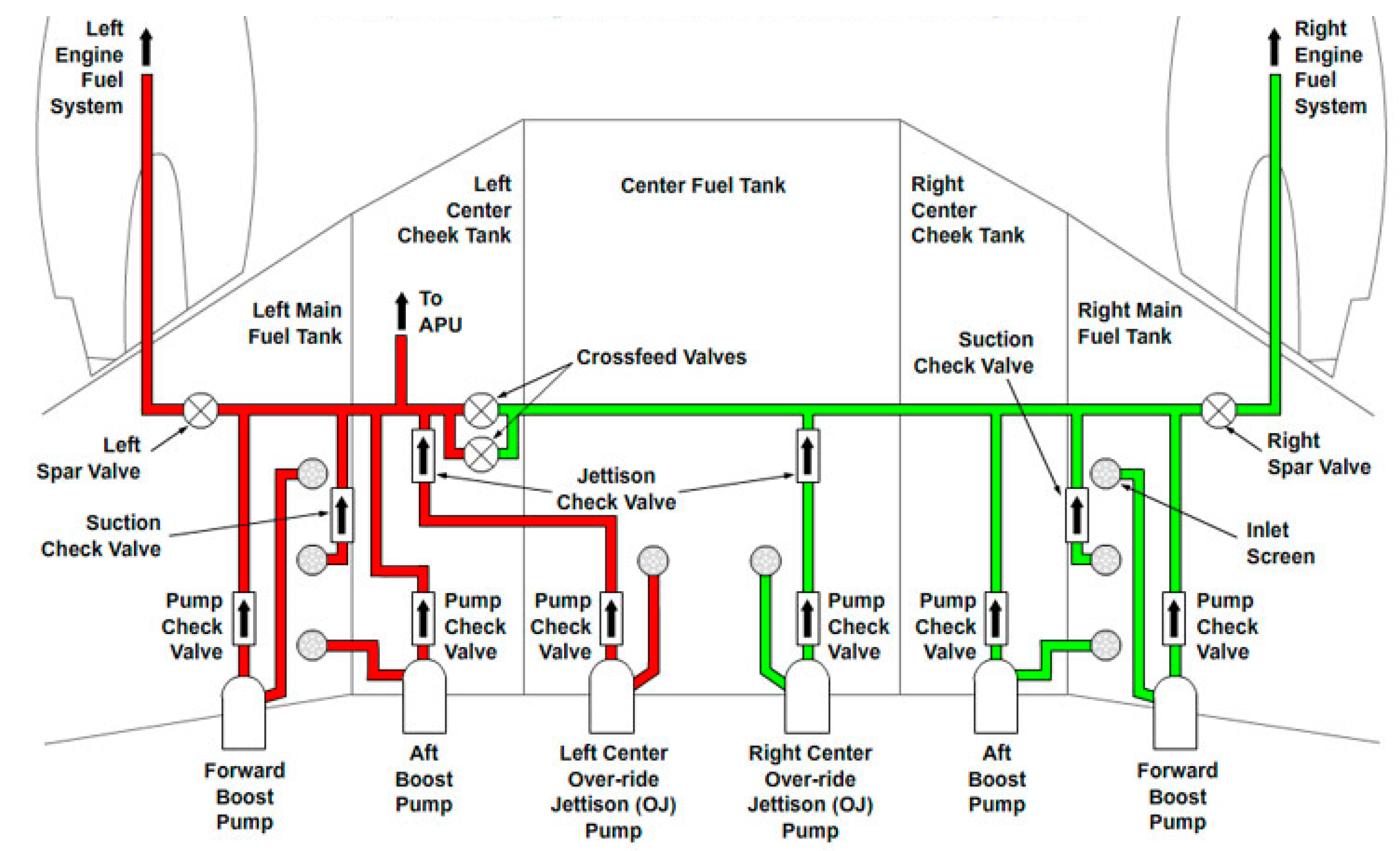
2.1. Boeing 777 Fuel System

The Boeing 777 is one of the most successful commercial aircraft of all time, with more than one thousand six hundred aircraft being delivered to airlines in the past thirty years. According to the ASN Aviation Safety Database, during this time, the aircraft recorded eight hull losses (damaged beyond repair), of which two were due to faults within the airframe systems, and one of them, at Heathrow Airport, from a fuel system failure (the other was due to a fault in the electrical system). It is used here to illustrate a typical commercial aircraft fuel system and its problems. The Boeing 777 fuel storage arrangement is similar in concept to Boeing’s previous twin-engine aircraft, comprising two wing tanks and a centre tank. The system’s main functions include fuel storage, fuel delivery, cross-feed, refueling, jettison, and defueling.

2.1.1. Structure and Function

Figures below show the schematic of the Boeing 777 fuel system, which constitutes two sub-systems: the airframe fuel system (Figure 2) and the engine fuel system (Figure 3). Fuel flows from the fuel tank to the main engine (upper left and upper right corners in Figure 2), and, after entering the main engine, the fuel enters the combustion chamber via the path shown in Figure 3 (from left to right). The airframe fuel system is in the wing box and fuselage. It is used to transport fuel from the fuel tank to the engine. The engine fuel system is in each engine’s nacelle. It is used to match fuel conditions (pressure, temperature, etc.) to the requirements of the combustor.
There are three crucial components for both the airframe and engine fuel systems: the boost pump, the Fuel-Oil Heat Exchanger (FOHE) and the fuel nozzle. The boost pump is the primary source of fuel kinetic energy before the fuel goes into the engine. The FOHE is used for heat exchange between the oil and fuel, to heat the fuel and cool down the oil. The fuel nozzle is located at the end of the fuel system; it is in the combustor and atomises the fuel before it is burnt.

2.1.2. Major Incidents

Research behind this paper found three significant Boeing 777 accidents related to the fuel system. The first accident occurred at Heathrow Airport on 17 January 2008 and the related aircraft was a Boeing 777-200ER from British Airways. This plane was on a flight from Beijing to London. When it tried to land at Heathrow, both engines had no thrust, and the plane lacked enough speed to manoeuvre. Due to some exemplary flying by the crew, the aircraft missed the M25 motorway and landed on the runway. The investigation concluded that when the aircraft passed over Russia, the atmospheric temperature dropped to −71 °C which was below the lowest temperature for the FOHE (−50 °C). Due to a lack of throttle excursion (almost perfect descent), ice still existed in front of the FOHE when the aircraft attempted to land. This ice blocked the FOHE and led to a sudden drop in fuel supply [17].
The second accident occurred in Singapore on 27 June 2016 and the related aircraft was a Boeing 777-300ER from Singapore Airlines. This plane was on a flight from Singapore to Milan. When the aircraft landed in Singapore (the pilots decided to fly back to Singapore because of an alert from the right engine), flames broke out from the aircraft’s right engine and rapidly spread to the whole right-wing. An investigation revealed the root cause to be a fuel leak in a narrow pipe in the FOHE, which caused the fuel to mix with oil and the mixture to spread throughout the engine. During the landing, a hot surface near the engine’s exhaust nozzle ignited the fuel around it and caused the disaster [18].
The third accident occurred in Bangladesh on 7 June 2016 with a Boeing 777-300-ER from Biman Bangladesh Airlines. This plane was flying from Dhaka to Saudi Arabia. When the aircraft took off from Dhaka, the pilots received a warning from the main engine and hence halted the take-off process and landed back at Dhaka. The investigation revealed that, due to contamination of the fuel nozzle, fuel did not burn properly in the combustor, and this caused the vanes of the Low-Pressure Turbine (LPT) to break through heat damage [19].

2.2. Potential Fuel System Failure Modes

The most prevalent fuel systems failures are due to the five faults listed below.
External leakage of the pump
Typically, the occurrence of external leakage is due to improper assembly, a loose connection, faulty gaskets, damaged threads and sealing surface, broken springs or cracked housings or bodies [20]. These will lead to insufficient fuel delivered to the engine (e.g., in the boost pump), or even let the fuel escape to the outside of the fuel system (e.g., in the main fuel pump).
Internal leakage of the pump
Internal leakage means the fuel travels from the pump outlet to its inlet through a small gap between gears and the housing [20]. It could influence the performance of the pump and could become more severe if the pump has not been regularly serviced. Finally, it will lead to the fuel flow rate and the engine thrust becoming lower than expected.
Clogged FOHE
The failure mode of a blocked FOHE comes from a real accident on 17 January 2008 (see above). There are a few tiny tubes inside the FOHE, and it is possible for their entrance to become blocked. The potential consequence of a clogged FOHE is a drop in the fuel delivery, which will cause lower engine thrust.
FOHE leakage
This failure mode comes from a real accident on 27 June 2016 (see above), which led to the engine catching fire. The FOHE has a unique structure to accommodate two kinds of fluid to pass through it (tiny ducts are for the fuel, gaps between them are for the oil). Due to these tiny ducts being fragile, the FOHE leakage is a possible failure mode for the Boeing 777, but the accident mentioned in Section 2.1.2 is the most severe one.
Blocked nozzle
Fuel nozzles are located at the delivery end of the fuel system and arranged in a circle in the combustor [19]. These nozzles spray a fine mist of fuel into the engine to maintain the engine’s power, consistent with efficiency and temperature margins. Nozzle degradation (blockage or contamination) directly influences the performance and even the safety of the aircraft.

2.3. AFS Summary

Benefitting from the development of sensor technology and maintenance strategy, health monitoring systems for the critical systems on the aircraft (including the fuel system) were devised to ensure their reliability. Some of these systems are: PlaneView (Gulfstream (Savannah, United States) and Honeywell (Phoenix, United States)), Electronic Centralised Aircraft Monitor (ECAM, Airbus (Leiden, Netherlands)), and Engine Indicating and Crew Alerting System (EICAS) [21]. These systems demonstrate the powerful combination of data (from sensors) and AI, which provides an effective way to detect and diagnose failures in the fuel system.

3. Experiment and Simulation Work

3.1. Experimental Work

The literature associated with fuel system experimental research has been reviewed. To broadly review the experimental work dedicated to fuel system research, the scope of the review was gradually expanded from aircraft fuel systems to other vehicles (especially automobiles), from which valuable common lessons may be gleaned to guide research on aircraft systems. The following paragraphs discuss these experiments/test rigs according to their research objects, which are varied, in the sequence of:
  • Fuel metering and pump system,
  • Icing problem,
  • Fuel filter and injector, and
  • Other vital components/functions (e.g., fuel measurement)
For the reader’s convenience, Table 1 summarises the references included in this section according to the research objects.
The Fuel Metering System (FMS) is a crucial component in a conventional aircraft fuel system; it is responsible for receiving signals from the Engine Control System to supply the required fuel flow for engine start-up, acceleration/deceleration, and stabilisation [22,23]. Typically, an FMS consists of the fuel pump, metering valve and differential pressure valve, which aims to pressurise the fuel, control the fuel flow rate by changing the orifice, and maintain a constant pressure difference across the FMS. In a study of external leakage of the Fuel Pump and Metering Unit, Ref. [24] used a simplified test rig to investigate how cavitation, due to a Helmholtz resonator, led to cavitation in the Pressure Control Valve. As an acoustic resonant structure, they found that a Helmholtz resonator can exist in the clearance within the valve, amplifying undesired pressure and flow fluctuations. The test rig assisted them in finding the reason for cavitation, observing the pressure fluctuation, and validating the solution (by placing a hole for venting). Ref. [25] developed an experimental rig to validate the proposed fuel metering method for an electric fuel system in a small-sized turbofan engine. They developed a control loop (Figure 4), in which the fuel flow rate feedback system not only measures the current fuel flow but can also compensate for the degraded pump’s impact by comparing the target flow with the fuel flow feedback from the Fuel Pressurizing Valve (FPV). However, their final metering/control accuracy (+/−5%) strongly relied on the accuracy of the fuel flow feedback, which further depends on two uncontrollable factors: pressure sensor performance and the manufacturing tolerance of the valve used on the rig.
Icing issues can directly affect aircraft safety, whether on critical surfaces (such as the wing, rotor, or engine to change the aerodynamics) or within the aircraft fuel system. Both classes of issues have led to several accidents in the past, but this section only discusses the latter issue. The ice in the fuel system comes directly from water which, when the temperature drops in flight, becomes ice which may block the fuel feed line. One of the most severe accidents, the crash of a Boeing 777 at Heathrow Airport in 2008 [17], is often cited. Figure 2 and Figure 3 show the layout of a Boeing 777’s fuel system. This is a typical fuel storage layout for a Boeing twin-engine aircraft, comprising two wing tanks and a centre tank [26]. Apart from the fuel tank, the fuel system also includes various valves, pipelines, heat exchangers, nozzles, boost pumps in the wing and engine fuel pump (including an LP centrifugal pump and an HP gear pump). Following the accident in 2008, the fuel system icing problem attracted more research attention. Ref. [27] proposed an innovative de-icing method based on the Fuel Oil Heat Exchanger (FOHE), modified by installing a bypass valve to switch the fuel flow direction and melt the ice upstream of the FOHE. The pressure at both ends of the FOHE can activate the bypass valve. Their simplified test rig verified the proposed method and simulated some emergencies. The system’s performance during the transition period of flow direction switching may need more attention, and the reliability (such as fault tolerance or a broader range of temperatures) of the device they proposed may need further verification. Ref. [28] reviewed an icing rig used in the ice accretion and release research conducted by Boeing, Rolls-Royce and AAIB to determine the cause of the abovementioned accident. The icing test programme used a multi-step procedure, which started from a simpler preliminary test rig (to gain more experience) and ended in a test rig that simulated almost the entire engine feed system, from the fuel tank boost pump to the engine low-pressure pump, to test the ice accretion and release individually. The test rig helped the researchers to accumulate considerable knowledge of fuel system icing behaviour. They replicated a fuel temperature as low as −40 °C, close to the actual circumstance when the aircraft flies over polar regions. As the test configuration can be customised (on the simplified test rig), they successfully found the worst scenario for the ice formation. Ref. [29] controlled another test rig, which had a glass window, to measure the transient icing process and to study the factors that can influence the characteristics of ice particles. They used exchangeable test bodies (with various shapes) to represent and test the ice accretion. The flexible test rig allowed them to perform eighty-two individual experiments to evaluate various vital parameters. However, because the test rig could not generate a flow rate larger than 1200 L/h, the test rig had a limited capability in the ice release test, which needed a much higher flow rate for replication.
Table 1. Experimental work for the most vulnerable components in the fuel system.
ReferencesTopicAim
[22,23,24,25]Fuel metering system (with fuel pump)Find potential failures affecting fuel metering and supply, develop more reliable metering methods
[27,28,29]Icing issueReproduce the accident and analyse the cause to improve the existing system
[30,31]Fuel filterExplore and resolve potential failures and challenges presented by new technologies/fuels
[32,33,34,35,36,37]Other vulnerable componentsAccurately measure fuel flow even when the flow meter fails
Fuel filter and injector systems in automobiles are responsible for the popularity of the GDI (Gasoline Direct Injection) engine. GDI technology improves engine efficiency, but poses new challenges, such as injector blockage. Blockage may be attributed to any deposit, debris, and contaminant in the fuel, which can influence the fuel filter and injector. Within this field, Ref. [30] developed a filter performance test circuit, which included several components, such as the pump, particle counter, heat exchanger, and vibration generator, to accurately match the target system. Their test facility can replicate extreme operation conditions with many external factors, such as temperature, pressure, flow pulsation, engine start/stop, and combinations. They concluded that fuel filtration could be affected by the car’s operation. They ran the system with a flow rate of 180 L/h for a long time to test the filter’s performance with different combinations of external factors. The filter was gradually blocked by debris during this process, which also made the filter not work as well as it should, and this could be worth further discussion. However, this factor was not mentioned in their discussion. Ref. [31] used a GDI bench engine test platform, based on a VW 1.4L TSI engine, to test different fuel formulations and observe the deposits at the injector nozzle (which can influence the engine’s working pattern and emission), and the selected engine’s susceptibility to different types of fuel. As they worked on a real engine the result directly reflects engine performance, and their work could be used to make an industry-standard test method for evaluating the injector’s cleanliness. However, their experimental work lasted for three months during which changes in the engine’s characteristics might be expected but were not addressed.
Other topics associated with fuel systems have been reported in the literature: flow modulators [32], refuelling [33], and electrostatic charge [34]. Furthermore, accurate fuel flow measurement is always a problem since the flowmeter needs to be placed directly in the flow field. Therefore, they are easily affected by factors such as contamination in the fuel, fluid property, turbulence, and fluctuation in the flow, including flow rate and pressure changes [35]. Apart from some advanced flowmeters, such as ultrasonic and electromagnetic flowmeters, researchers also worked on alternative ways of measuring flow. In their research on the electronic control unit for an aviation diesel engine, Ref. [36] worked on a common rail system injector test bench (STPiW3) with the aim of achieving a precise fuel dosage. STPiW3 can test various types of diesel injectors. The research used the pressure as the control signal (to activate mass flow rate measurement) and determined the mass flow rate by using the mass of the fuel and time. In other words, as they treat the mass flow rate as a function of mass and time, the accuracy of the calculated mass flow rate may suffer from the propagation of uncertainty from the parameters mentioned above. To alleviate this negative influence, they considered the difference in some measurements when they developed the control algorithm for the electronic control unit. Ref. [37] investigated how to make the fuel supply system deliver the desired fuel flow even when the flowmeter is faulty. Based on existing fault diagnosis and prevention methods for transducers (e.g., dual-redundant system), they started from first principles to estimate the flow rate by using the measured pressure and polynomial regression on the pump characteristics. They used a test rig to verify the proposed method, and, despite the fitting and measurement error, it could yield a viable way of verifying or replacing the reading from a suspected faulty flow sensor.
Aligned with the discussion presented in this section, most experimental work is performed on scaled test rigs rather than a full-scale testbed, as it may not be easy to check degradations or premature failure on each component in the real machine, and a stricter operation procedure with more safety considerations would be needed. Summarising the advantages of such an approach, given in the text above, the following list emerges:
  • Scaled rigs give timely results that are less expensive than testing the full system.
  • It is easier to discover the nature of problems and the correlation between factors, e.g., Ref. [38] used a simplified fuel rig to determine the best indicator of each degradation mode within their research and the correlation between those indicators.
  • They can accurately and repeatably replicate problems, e.g., Ref. [39] used a simplified test rig to replicate different component degradation modes in an accurate, repeatable, and efficient way.
  • Scaled rigs can be used to link computational models to real systems, as experimental results can be used to compare the output from both sides, e.g., Ref. [40] used a fuel delivery system rig to verify a model-based diagnostic algorithm, analyse fuel system’s behaviour and compare with the data from an actual fuel system.
  • The configuration of an experimental rig is more flexible than a real system. For example, faults can be inserted into the test rig using the required method with any desired severity. This feature is essential if there are safety concerns about performing similar tests on the actual system.
  • The target system can be isolated from other systems to prevent extraneous interference factors, e.g., Ref. [33] assessed the performance of a Fuel Filler Tube Check Valve in their research. They installed the valve on a tank located on a shaker table to isolate it from any other vehicle dynamic factors.
Even though having a pretty simple system can lead to many benefits, only a few researchers have produced a simple fuel rig with benchmark quality. Ref. [41] developed a test rig referencing the work of [39] and added a spill bypass and a cross-feed line to the test rig. It can replicate either healthy or several degraded scenarios. The data produced from it has been used to train various health monitoring algorithms (e.g., Naïve Bayes, reasoning system, clustering approach) associated with the aircraft fuel system [42,43].

3.2. Fuel System Simulation

As a fast, economical, safe, and efficient research approach, simulation modelling has been used in the aviation industry for various purposes, including aircraft design [44], optimization [45], manufacturing [46], air traffic management [47], pilot training [48], accident investigation [49], and MRO (Maintenance, Repair and Overhaul) [50]. For the fuel system, simulation can assist the system’s design, verification, and optimization processes.
In principle, it is possible to solve the equations governing the flow through fuel systems by either analytical or numerical methods. However, for analytical methods, the flow equations have to be quite simple, reflecting simple flow situations. As applications of interest are almost always on complex systems, research attention has been focussed on the numerical (computational) methods addressed here.
Numerical modelling uses numerical analysis, such as explicit and implicit methods, to solve the governing equations. Ref. [51] used the combination of 1-D and 3-D numerical modelling to solve the compressible multiphase Navier–Stokes equations with the GT-SUITE solver for the aircraft fuel system. Their proposal was based on the balance between the model’s fidelity and computational time. A 1-D model can produce a low-fidelity system-level solution in a short runtime, while 3-D modelling is suitable for high-fidelity modelling of a fuel tank with a complex shape. However, the latter is computational and costly and takes time. Similarly, Ref. [52] used the Modelica Fuel System Library in the 3DExperience platform to perform simulations, which also used 1-D and 3-D modelling. They aimed to use their model to investigate the thermal management problem in the aircraft fuel system and used a case study to validate the proposed methodology. If the equation set has to be solved in real time, the corresponding model is considered ‘Dynamic’ [23,53]. Ref. [54] developed a dynamic mathematical model in their research. The model was developed in one dimension, as they believed this was sufficient to simulate the system operation of pumping the fuel from the fuel tank to the engine, using the control software SimInTech. If the equations are time-invariant, i.e., the answer will not change over time, it is considered ‘Steady-state.’ For example, Ref. [55] developed the Fluid Network Model (FNM) in Simulink, which is dedicated to simulating the fuel flow’s steady-state condition, regardless of any transient surge effects. In addition, they used this approach to generate a generic component library and program the interface, in C, to link their model to other external platforms. As the full set of equations can sometimes not be solved without experimental input, it can be more convenient to use characteristic experimental data to replace the algebraic equations that represent component performance. Apart from the simulation work discussed above, some researchers prefer to use mature CFD (Computational Fluid Dynamics) software to get information about the flow field directly. Ref. [56] used a CFD model in the GT-POWER platform to simulate the pressures and temperatures within a vehicle’s fuel system with various kinds of fuel. Comparison with the experimental data indicated that the simulation result (fuel consumption and exhaust emission) deviated from those of the actual system. One probable reason is that they did not consider engine degradation in the simulation. Ref. [57] simulated a UAV fuel system with a 1-D CFD technique in Flowmaster. It produced a solution with a short runtime and was deemed suitable for the study of the system’s overall behaviour. Finally, Ref. [58] built a CFD model for a low-pressure pump test rig (including valves and pipelines). They stated that the simulation model not only reduced the time and cost for their research (as they did not need to purchase and work on the hardware) but that it could also deliver detail which was not easy to measure from the experiment (such as pressure and flow condition in small gaps/clearances in the pump). This was also mentioned by [59]. However, their model needed at least 24 h for one simulation on a quad-core laptop, and the simulation result only corresponded well with the experimental result for low pump speeds.
Simulation modelling can be applied to various stages in the product’s lifespan, starting from the conceptual design to the end of the service. This procedure has been adequately summarised as six discrete domains in the UK MoD (Ministry of Defense) System Engineering Lifecycle, also known as the CADMID (Figure 5). With an aircraft as an example, the simulation model only needs to estimate several parameters in the initial (conceptual) design stage and hence would employ a 1-D model. When the detailed design begins, a 3-D or 4-D simulation must be considered. Within this process, simulation and experiments will be used in combination iteratively for further assessment and verification. If focus is placed on the design phase in the CADMID cycle (the phases before manufacturing), the impact of simulation modelling may be categorised into the following four aspects:
Preliminary design and optimization
Fuel system simulations are primarily used for preliminary design and system optimisation ([54,56,59,60]). They can represent the system at a conceptual level and provide a platform for the improvement on the system’s construction or algorithms. For example, Ref. [61] discussed applying Smartfuel on a dual-engine helicopter. Smartfuel aims to use intelligent fuel components to replace the conventional central fuel computer, simplify the system’s structure, and make maintenance more efficient. As a first step in their research, a simulation was developed in Simulink to model the internal process between the smart fuel components and the fluid dynamics of the entire system. In this way, the simulation model was used to verify the proposed system before deploying to ground and flight tests. Furthermore, Ref. [60] used a set of engine specifications and Compressed Natural Gas (CNG) fuel characteristics to develop a simulation model in software called Ricardo Wave, to find the optimal working point of an engine using CNG.
Estimate system performance and guide the experimental work
The simulation model can also predict the fuel system’s performance and guide the experimental work. Ref. [23] used a simulation model (named Amesim) to simulate a new fuel metering system which included a gear pump and a centrifugal pump. Based on the pump characteristics, an aviation turbofan engine could use the gear pump to start the engine and work at a low pump speed while the centrifugal pump works under a higher pump speed to pressurise the fuel. Their model focused on the pressure changes during the transient state when the fuel metering system unloads each pump to switch to another pump mode. Within their work, they simulated the section between these two pumps and studied how to remove flow pulsations and high-frequency pressure fluctuations. As their model was a simplified version, using an idealised way to simulate pumps and valves, it may need further assessment/verification for use in a realistic environment. Ref. [62] improved a diesel locomotive engine’s fuel system to enhance efficiency and reduce emissions. To reduce cost, they developed a numerical simulation model in the Diesel-RK program before the bench test to assess how the fuel system’s parameters impacted Internal Combustion Engine (ICE) performance. In this way, they found out the best configuration for the experimental work, e.g., the optimal number and size of holes in the nozzle atomiser.
Assist researchers on other techniques
Some researchers used simulation to assist other techniques [55]. For example, Ref. [63] developed an ANFIS-based (Adaptive Neuro-Fuzzy Inference System) intelligent diagnosis tool to optimise the fuel tank control signal from the fuel consumption and fuel flow. The ANFIS algorithm had a five-layer structure based on an expert system with logical rules. Their simulation model referred to the work of Breda and Beno, which was published in 2013, that could generate the engine fuel consumption signal and fuel flow in the tank, to feed the proposed diagnostic algorithm. However, their method only focused on a fuel tank fault and the model in Simulink generated all training and testing data for the diagnostic algorithm in 20 s.
For safety analysis
Ref. [64] proposed a 2-D numerical multi-physics model to simulate the “snow showers” phenomenon. This occurs when a significant amount of ice is released suddenly in the fuel system due to an increased fuel flow rate (change in engine thrust). This can directly threaten the safety of the plane by blocking components with small holes (such as a filter). To balance the model’s complexity and scale, they assumed the filter as ‘ideal’ (can be blocked by any kind of particle), which may make the simulated result deviate from reality. Ref. [34] introduced a simulation model developed by BAE Systems for Airbus to predict electrostatic charge behaviour and identify the source of it. This model is named EC-Flow, which can simulate the build-up and decay process of electrostatic charge before it goes into the fuel tank (refuel). By comparing the experimental data from a simple component (a metal pipe), the simulation result achieved a similar trend to the experimental data.
Therefore, the main benefits of using simulation modelling in the fuel system diagnostic research are listed here:
  • By using simulation, researchers can control [56] or observe [58,59] parameters that are not easy or impossible to manipulate and measure in the real fuel system.
  • Simulation can be used as accelerated degradation testing for the fuel system, such as fuel degradation or deposits in components, by using such acceleration factors to bridge the accelerated and non-accelerated failure time [65].
  • Simulation modelling can be extendable and reusable to adapt different fuel systems. Ref. [55] worked on a simulation model named Fluid Network Model (FNM), which was developed originally for the Airbus A380, but has been re-used in the HIL (Hardware In Loop) facilities of A400M, A350, A330/340 and A320.
Simulation modelling also has some limitations that need to be improved in the future:
  • According to the reviewed literature, some simplifications and assumptions the researchers give at the beginning can make a simulation deviate from reality. For example, they could neglect some of the degradation factors in the actual machine [56] or be limited by the target and desired complexity of research [64].
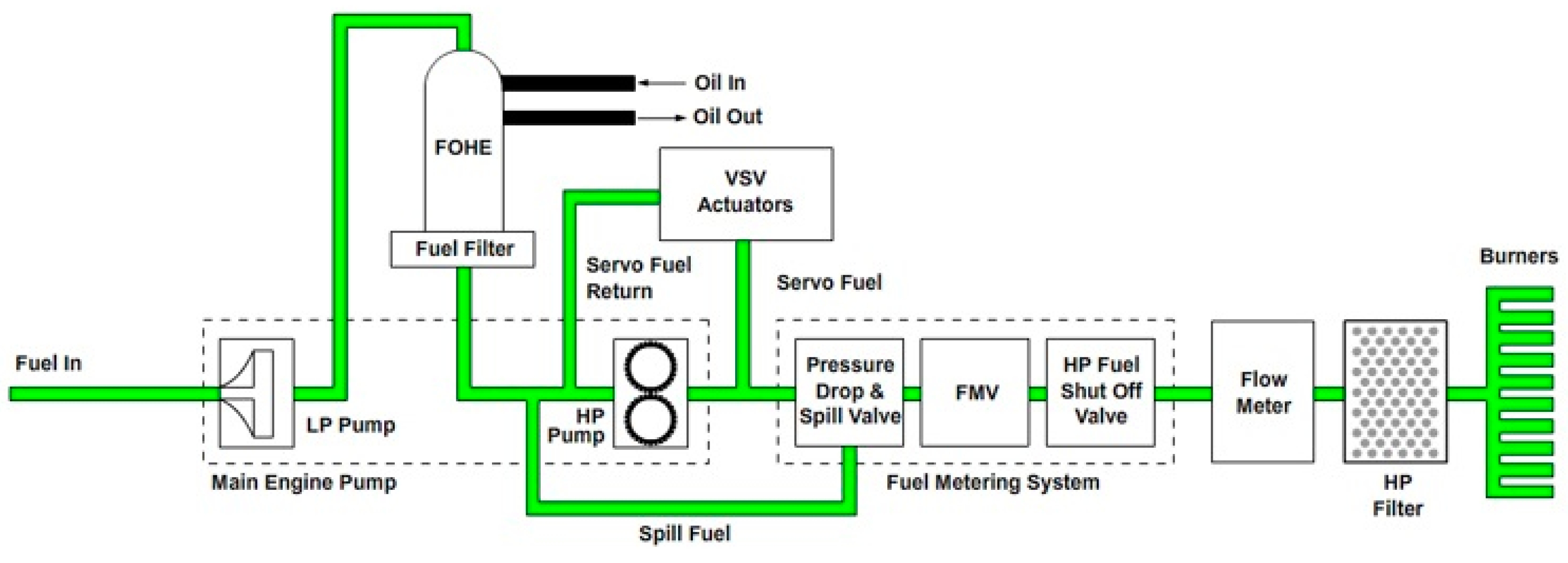
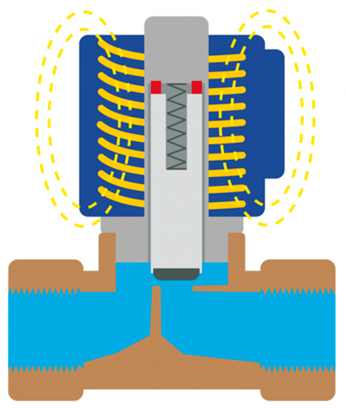
  • The consistency between the simulation and experiment is another problem that needs to be considered, especially when the experimental result is used to verify the simulation model. Except for the simplification factor just discussed, two other possible reasons arise. On the one hand, sometimes some specifications (and their combination) of the actual machine/system are unknown, or the measurement for them is not included in the main objectives, which can make the simulation lack some necessary inputs and cause deviation in the simulation output. For example, Ref. [66] simulated a fuel injector system in the pre-chamber of an Internal Combustion Engine and the pre-chamber was used in the stage of ignition to reduce fuel consumption and toxic emission. However, some parameters of the gas injector were missed in the manufacturer’s data sheet; finally, six geometrical parameters were determined by reverse engineering (by sectioning the injector physically), two functional variables were estimated based on research experience, and another two parameters were modified by a response optimization solver (with Gradient Descent Method) in each iteration. On the other hand, the performance of the simulation model could be limited by the configuration of the selected simulation tool. As most of the mainstream simulation software is becoming more generic, it can be considered the baseline and applied on more occasions. It is the opposite to the characteristics of some custom software and makes them (the universal simulation software) unable to simulate every component perfectly without using some programs that are developed individually. For instance, when the current lead author tried to simulate a solenoid valve in Simulink, a broad-used multi-domain simulation tool, the orifice of the Two-Way Directional Valve (provided by Simulink) has a linear relation to the spool’s position. However, according to the schematic of an actual solenoid control valve shown in Figure 6, the flow path (with light blue colour) in it contains bends and variant orifices, which is entirely different from what the Simulink model described, and the difference could become more evident with a smaller opening. Similarly, Ref. [67] mentioned that a pressure drop more significant than their simulated result was observed in the experiment, which could be attributed to the same reason, as their model for the solenoid valve in SimulationXTM was simpler than the reality.
  • The final part concerns the contradiction between the model’s efficiency and accuracy (or coverage), which is another essential factor impacting how researchers simulate the fuel system. Firstly, a simple model for the fuel system, such as a model without spatial dependency or a 1-D model (with the spatial dependency on one axis), could run faster (with higher efficiency), but it may be impossible to describe the parameters’ distribution in all directions of a complex shape (e.g., fuel tank). For instance, to make the model’s runtime shorter, the steady-state model (for the Airbus A380’s fuel system) in [55] was developed in Simulink (a high-level programming tool) and did not consider any transient effects from the fuel flow, while [54] simulated the fuel flow condition outside the fuel tank with 1-D modelling. On the other hand, some complex models or modelling the fuel system in higher dimensions can output more information with higher accuracy, such as the system’s transient behaviour or parameters in every direction within the fuel tank or pump, but need much longer runtime [51], which could limit their application in some scenarios such as real-time control [63] and real-time simulation [55]. To solve this problem, dimension-reduction modelling [51] could be a potential solution in fuel system research. It aims to improve efficiency by replacing unnecessary high-dimensional simulation with low-dimensional simulation in some areas (such as pipelines) and keeping the original (complicated) model for the problems associated with topics like complex geometry and multiphase dynamics. Therefore, it seems that the most appropriate choice should be based on a comprehensive evaluation of the final request/target. Other cases where researchers dealt with complexity in this way include simulating the fuel system in a 2-D domain [64], combining a dynamic mathematical model (for the whole system) with a 1-D model (for the critical component) [66], or using 1-D (system) simulation plus a 3-D (fuel tank) simulation [52].
Table 2 summarises the existing simulation work for the fuel system discussed in Section 3.2, with their position in the reference list, simulation target, the type of modelling, and the software used.

3.3. Summary

As two common research methods, experiment and simulation have been widely used in the research of fuel system fault diagnosis. This section discussed some cases in detail and summarised the connections between these two approaches and their advantages and disadvantages. The next section will discuss how to use the collected knowledge and data, especially with Artificial Intelligence methods to diagnose the fuel system.

4. AI-Based Diagnostic Techniques

This section briefly reviews several AI-based approaches, specifically addressing reasoning-based and Machine Learning (ML) based methods, along with their application to fuel system fault diagnosis. Rather than comprehensively analysing every AI-related technique, the emphasis is placed on a selection of representative and mature methodologies that effectively reveal the distinctions between their self-explainability, which experiences a gradual shift from transparent (reasoning) to opaque (neural network) working process, and the potential impact on practical maintenance tasks.

4.1. Reasoning-Based Diagnostics

This section briefly summarises how reasoning can be used to diagnose faults in fuel systems based on knowledge. AI represents the capability of a computer (or machine) to perform tasks that normally require human intelligence or knowledge. As a typical AI domain, the reasoning mechanism can extract information from knowledge. According to the source of the knowledge, two types of reasoning are discussed: knowledge-based and model-based, along with their application to the research of fuel systems.
Table 3 summarises the references discussed in the following paragraphs according to their topic.
Reasoning with a knowledge base
As an essential part, a knowledge base is typically used to store the expert’s knowledge of the fuel system for inference, which is the evidence of reasoning. It mainly contains a rule base, which can be extracted from the manual [68] or defined by the experts in terms of the fuel system’s working principle, fault diagnostic tree, the possibility of fault occurrence, and how to deal with the fault [69] in the health management study of the fuel system. Sometimes, the knowledge base can include a case or fact base. The former includes past information or solutions that aim to seek and reuse the answers of a similar case on a new problem. It will need assistance from outside if there are no suitable cases, but the new case can be added to the case base as an update. The latter aims to match the condition (IF part) of rules to the current symptom or is used as the handle for rule matching in many cases. However, there are still differences in the role of the fact base in different studies. For example, Ref. [69] used the fact base to accommodate all predictable facts of the aircraft fuel system that can be output from reasoning. Ref. [70] used the facts to describe the status of the fuel system’s components and other associated information (names and locations). For example, if a particular fact was determined as “true”, a failure may exist. Eventually, their algorithm contained around three hundred facts and one hundred rules. Ref. [43] described a failure attribute database, which contained attribute information on each failure mode. It has a similar function to the previous fact base.
Knowledge-based/rule-based reasoning has been widely used in past decades, as it can work well in maintaining a simpler system or asset and the decision-making process is transparent [71]. The expert system could be one of the most representative applications of knowledge-based reasoning. It was initially developed in the 1960s and includes components such as the knowledge base, inference engine, database, and explanatory interface. The expert system’s rule base consists of a set of rules in the form of ‘If x Then y’, where the IF part of each rule is the antecedent (or premise/condition) and the THEN part is referred to as the conclusion or consequence. Expert systems also have an inference engine to evaluate the rules against a goal using either forward or backward chaining. The line of reasoning behind the final solution is automatically known and hence provides a clear level of explainability behind the final solution. As early as the 1990s, expert systems were applied in fuel systems. Ref. [70] discussed the Vehicle Management System (VMS). The VMS was developed by McDonnell Aircraft using the programming language CLIPS developed by NASA in 1985. It includes two expert systems, and the fuel expert system is one of them, which was embedded in the control computer for failure detection. Furthermore, Ref. [72] developed an expert system to achieve intelligent fault diagnosis for a fuel injection system by observing the pressure waves within the fuel pipeline. However, the knowledge base was built up for a particular diesel engine, which means that they need to expand the knowledge base (which could be done manually) to broaden the usage domain. After that, Ref. [69] used CLIPS to develop an expert system for fault diagnosis in the aircraft fuel system. Their knowledge base was based on the fault tree from the failure mode analysis and can provide reconstructive suggestions (to deal with the fault). Recently, Ref. [43] proposed a Framework for Aerospace Vehicle Reasoning (FAVER) (Figure 7), which is a vehicle-level expert system incorporating reasoning, to isolate faults cascading between aircraft systems. The knowledge base, used by the expert system, contains a relationship matrix created at the vehicle level by experts to establish the interactions between aircraft systems. The reasoning algorithm carries out the rule-based reasoning via forward chaining.
According to the cases of using knowledge-based reasoning in the fuel system, conventional methods still need further improvement. Firstly, it is about the rules’ properties, which attribute to the potential constraints (e.g., rule coverage) and interactions between rules and may lead to lower processing efficiency. Successful knowledge-based systems tend to rely on routine maintenance of the ruleset to ensure an adequate level of diagnostic coverage is maintained. Diagnostic coverage can also be heavily influenced by the extent to which original domain knowledge was captured during the knowledge acquisition phase and subsequently encoded as rules in the system. However, Rule-based Reasoning (RBR) and Case-based Reasoning (CBR) can be used together to alleviate this limitation. As discussed above, the reasoning in CBR is mainly based on previous solutions and empirical knowledge. Ref. [68] used both RBR and CBR to build an expert system for fault detection in an aero engine. The rule base was built from the manufacturer’s manual with forward reasoning, and RBR was applied in the normal scenario. The case base was constituted from some samples with endoscopic images and CBR was used to improve the efficiency of RBR in some challenging problems or emergent circumstances beyond the manual’s coverage. Furthermore, CBR is believed to be able to deal with the ambiguous diagnosis caused by unclear rules by using successfully solved problems [73]. Another potential limitation of knowledge-based reasoning systems relates to the process of knowledge acquisition, which often needs the support of experts’ understanding of each failure mode and will directly impact the quality and quantity of the involved knowledge. Ref. [69] systematically discussed how they acquired the knowledge in their research, which included aircraft fuel system’s failure modes and diagnostic experience from engineers, a fault tree that summarised from tests and outfield practices, faults’ original probability and expert’s opinions, as well as the handling process of some faults. However, they admitted that acquiring this information is a challenging task which requires much time and effort. In another paper by the same authors [74], ANNs were used as a knowledge acquisition tool to assist their “expert system”. They first decomposed the fuel system into many components and trained an ANN on each of them. Secondly, they saved the weight and threshold in the knowledge base, which can be treated as an automatic way of knowledge extraction. They declared that their method could identify multiple faults (up to two), and that the ANN made the inference process faster. Furthermore, Ref. [75] similarly improved the Expert System for a diesel fuel system. Routine knowledge base maintenance should also be considered and needs to be performed routinely to ensure adequate coverage of the knowledge base throughout the assets working life. Ref. [76] addressed this by introducing an architecture (sketched in Figure 8) that combined an expert system with a neural network. The double arrowed line between the knowledge library and the Neural Network (NN) module is highlighted (in red), which indicates that the NN reasoner can utilise the information stored in the knowledge library and is additionally able to prompt the developer/user to update the knowledge library with any new instances. The NN reasoner will then be retrained based on the updated contents in the knowledge library. From the description above, it is easy to find that the expert system was only used to manage the knowledge library and provide explanations. However, firstly, the knowledge needs to be acquired manually. Secondly, as the NN overtook the reasoning process, it will not be as transparent as the conventional expert system, limiting the explanation mechanism’s performance. Ref. [43] were dedicated to expanding their FAVER architecture by including new faults and new systems with minimal change to the framework. Therefore, updating the knowledge base more efficiently is still an unresolved topic.
Model-based Reasoning
In the reasoning-based diagnostic research of the fuel system, the knowledge can be expressed as a series of rules provided by an expert or represented in a physical model (or a mathematical model obtained from physical knowledge), which is referred to as model-based reasoning. The following discussion starts with a simple demonstration and then the qualitative and quantitative models used for fault diagnosis in the fuel system.
As discussed above, in rule-based reasoning (such as the expert system), the rules represent the expert’s opinions and experience on a particular system (fuel system) or asset to build up the relationship between parameters and results/solutions. If the rules belong to the heuristic rule, the inference engine may carry out relatively shallow heuristic reasoning, such as forward and backward chaining. This characteristic aims to achieve a shorter runtime. In model-based reasoning, the model could be structural, functional, or causal, which can reflect the essence of the system in a specific aspect and represent a more profound understanding of the system than the heuristic rules mentioned above. Figure 9 shows an example of how to model a vehicle engine qualitatively, which can be used to isolate a potential fault. Before starting the engine, several conditions need to be met. For example, the starting system must rotate first, and all spark plugs must work well. If it is assumed that the starting system does not work (marked by the red box), but the battery works as usual (marked by the green box), the circuit may be open (black dashed line box). However, most of the time, this type of problem is not easy to observe, which means the above diagnostic (reasoning) process will rely on understanding the entire system.
Regarding the models of assets/systems, a typical way is to divide them into qualitative and quantitative models. The qualitative model includes but is not limited to the process model, the functional model, and the causal model, which has been applied to the fault diagnostic research for the fuel system [77]. Other researchers, for example, Ref. [78], developed a Timed Failure Propagation Graph (TFPG) to achieve an effective fault diagnosis in the vehicle fuel system. TFPG has a directed graph structure which can identify the propagation paths of failures in the system. Based on the fault signature, the TFPG reasoner will search through all the paths to provide the prediction (failure mode candidate) and explanation. Due to the considerable number of sensors and fault signatures across the entire system, the diagnostic knowledge and reasoning process is pre-compiled to reduce computational costs, which is different from the process within rule-based reasoning. Ref. [79] discussed the design process of IVHM, which includes sensor (location) optimization and the making process of diagnostic rules. To achieve these two targets, they developed a qualitative functional model, using the MADeTM software, and applied it to the fuel rig for failure assessment and knowledge extraction. Their model uses functions and flows to describe the system, such as energy flow, signal flow and material flow. They also mentioned other model-based reasoning software tools, such as eXpressTM (DSI Int., 2012), and TEAMSTM (Qualtech Systems Inc., 2012), which could give more inspiration to other researchers. However, they admitted that the functional model constantly needs system designers’ and reliability engineers’ input and updates. This point may become another limitation of this approach (apart from the computational costs). To make model-based reasoning more efficient, Ref. [80] developed a software named LYDIA (Language for sYstems DiAgnosis), which includes a modelling language (for model compiling) and a reasoning tool for faster reasoning. They applied it to a light aircraft fuel system, and the proposed software alleviated the complexity of the diagnosis computation within this process. Ref. [81] provided a detailed discussion on how to use LYDIA to model the system qualitatively and how the complexity of the model affects the inference time. They applied the LYDIA software to the fuel system of Airbus 330, a system with fifty-one observable variables and forty-six components in their experiment, with the failure mode of fuel leakage. In their opinion, model-based diagnosis (MBD) is better than some symptom-based methods in diagnostic tasks as the (developed) model only needs to be amended on the places that have been changed in the actual system without rebuilding the reflection from symptom to the root cause. However, they admitted that the model’s fidelity and diagnostic inference speed of the algorithm is an inherent conflict which needs to be decided by the user.
Compared with the qualitative model (discussed above), the reasoning method used by quantitative models is more straightforward, which will directly compare the observations with the expected scenario that is output from the quantitative model (such as the mathematical model). Other techniques like parameter estimation [82] can be applied further to assist the inference in obtaining the diagnostic result. For example, Ref. [83] researched reliable control systems for the fuel management system, which consisted of a control module, a diagnostic module, and a controller reconfiguration module. For fault diagnosis in the fuel system, they developed a mathematical model derived from physical principles, and the diagnosis was based on the residual between the mathematical model output and measured parameters. Their method was validated on a throttle sensor fault and injector fault. Similarly, Ref. [84] combined the (quantitative) model-based diagnosis with the control system again to propose a fault-adaptive control system (FACT). Their method employs a simple model (e.g., Bond graphs) of the system and signals for detecting the deviation of the measured behaviour from the expected behaviour. They applied the proposed method to an aircraft fuel system, which successfully detected the degradation at the fuel pump (with the magnitude of the parameter change) and finally reconfigured the system according to the diagnostic result. Ref. [85] compared the performance of a model-based and data-driven approach to diagnosing LRUs (pumps and valves) in the aircraft fuel system. Finally, he indicated that the model-based method could capture more physical characteristics, which ensures the faults can be traced back to physically meaningful parameters. However, modelling and reasoning in higher-order dynamics could be challenging work. Ref. [86] included a case-based reasoning system in the model-based diagnosis to propose an Experience-Aided Diagnosis (EAD), where the residual between the model’s output and the testing result was used as the symptom to index in the records. They concluded that MBD allows a deep insight into the process behaviour of the system. However, the inherent computational complexity, lower fidelity of the model and imperfection of human knowledge will limit MBD’s diagnostic performance. As model-based and rule-based reasoning comes from expert knowledge, they can only deal with foreseeable failures and are often ineffective in unforeseen circumstances.

4.2. Machine Learning-Based Diagnostic Algorithms

Machine Learning (ML) methods, also known as data-driven approaches, are very efficient at deriving valuable relationships and mappings between system parameters from data for classification and forecasting and hence offer an effective solution for diagnostic applications. This subsection explores, at a high level, the applications of several supervised ML methods in the fuel system, with gradually increasing degrees of model complexity and hence the inherent difficulty in providing explanation of their operation.

4.2.1. Decision Tree

As a tree-like directed acyclic graphical model, Decision Tree (DT) extracts rules or relationships between parameters from data rather than expert knowledge, which is the most significant difference from the reasoning-based approaches discussed in Section 4.1. For fault diagnosis in the fuel system, they are typically used for classification applications. The structure of a DT consists of various nodes, branches, and leaf nodes. The nodes represent the test on the attributes (or measured parameters); branches indicate the outcome of the test and leaf nodes hold the class labels (or diagnostic results). The overall logic is self-explanatory. From an early C4.5 algorithm developed by [87] to the latest Random Forest algorithm, the predictive performance is becoming more robust, but at the cost of loss in the model’s ability to provide a clear explanation of reasoning.
As a classic machine learning method, the decision tree has been applied to the diagnosis of fuel systems for more than 20 years. Ref. [88] used an ID3 Decision Tree to build up an on-board diagnostic system for the common rail fuel delivery system in the car, which benefits from an easier compiling process, lower memory occupancy and shorter runtime of using the decision tree. A qualitative model was used off-board to generate the deviation of the system’s behavior (symptom) and a decision tree mapped the symptom to the recovery actions. In recent years, as more machine learning methods have been deployed in fuel systems, decision trees are usually not used alone but are used in most cases for comparison with other data-driven methods. For example, Ref. [89] used three ML approaches, SVM, kNN and DT, in a diagnostic task based on the data collected from the experiment on the fuel system. Although the decision tree still has a good running speed, it showed the worst performance among the three candidates. According to their results, DT is not sufficiently sensitive to certain early failures (such as leakage) and the faults have similar symptoms (such as blocked valves and nozzles). In addition, compared to other methods, the performance of DT is more dependent on the sample size, which means that DT is more likely to get poor diagnostic results when the sample size is small. Based on these three candidates (SVM, kNN and DT), Ref. [90] added a Random Forest (RF) for comparison. They used these four methods for potential fault detection in four vehicle systems, including the fuel system. In their study, DT still achieved poor prediction results, but the performance of a random forest has been able to approach the other two methods (SVM and kNN). As an integrated learning method, the structure of a random forest contains multiple decision trees, and the final output is obtained from the output of all trees in a certain way. Since this pattern reduces the model’s explainability, their results indirectly illustrate a conflict between machine learning algorithm performance and explainability. Recently, Ref. [91] used RF and Support Vector Regression to estimate the RUL of components in the aero-engine fuel metering device. They verified their approach on a simulation, and RF was used in another way to select the most significant features by calculating the importance score of each feature for the specific failure mode.

4.2.2. Logistic Regression

Classification and regression (function approximation) are two main tasks of ML tools. Classification methods aim to predict discrete or categorical values, whereas regression applications tend to predict continuous values. For example, Linear Regression provides the simplest form to model the regression function as a linear combination of predictors to represent the relationship between a response variable and one or more attributes. As a classification approach, Logistic Regression (LR) applies a sigmoid function to map the output of Linear Regression to the field between 0 and 1, which can be treated as the probability estimate of the response variable is equal to 1. By using a given threshold (between 0 and 1), the model’s output will drop into two discrete classes, which can be used in classification problems.
Although LR (and related techniques) has been used as a data analysis method for maintenance and fault diagnosis in the aviation industry [92], for example, the diagnosis of UAV [93] and Aeroengine RUL prediction ([94,95]), it has rarely been applied to fuel system diagnostics as the current review only identified one relevant article [96]. Therefore, considering the applications of LR in other domains and the interpretability given by its simple architecture, it would be interesting to apply Logistic Regression to fuel systems.

4.2.3. Support Vector Machine

As a powerful tool for classification, Support Vector Machines (SVM) have received widespread research attention in past years, as they offer solutions to many of the problems encountered by other learning algorithms. SVMs attempt to solve classification problems by placing a hyperplane decision boundary between points of different classes, which could be non-linear, and makes the SVMs able to solve problems that are not linearly separable. This capability benefits from the “kernel” within the SVMs, which performs a non-linear mapping into a higher dimensional space in which the classes become (in most cases) linearly separable.
SVMs have been successfully applied in the fuel system for fault diagnosis several times. Apart from the two samples mentioned in Section 4.2.1 [89,90], Ref. [97] applied an SVM with optimised parameters in a diesel engine’s fuel system for the fault diagnosis. They found that compared with neural networks, SVMs can achieve better training results with a limited number of samples, and are less likely to fall into local optimum and overfitting problems. By collaborating with General Motors (GM), Ref. [96] used SVMs to detect potential failures in the early stage within a high-pressure fuel system in a car, which delivered high-pressure fuel to the cylinders for combustion. They pointed out that SVMs need a much longer runtime than other ML methods and the performance of diagnostics is greatly affected by hyperparameters. Therefore, they used a grid search method to find the best set of hyperparameters for the SVM. Observing the learning curve, they believe that SVMs are the best solution. Similarly, Ref. [98] built a fault diagnosis simulation system for a marine diesel fuel system using SVMs with optimised parameters. Their method recognised between one normal work condition and four faulty cases and achieved a 96% accuracy on the testing data. Furthermore, Ref. [99] used SVMs with the optimised parameter in a fuel injection system with limited samples, which benefits from the SVM’s good performance on small-sample pattern classification, nonlinear mapping, and high-dimensional problems. However, they stated that SVM did not achieve satisfactory test results despite the high training accuracy. The author speculates that this result may be due to the difference between the coverage of the training set and the testing set, as this problem can easily occur in the scenario with small samples. Finally, ref. [100] developed an adaptive fault diagnosis technique for an aircraft fuel system using multi-class SVMs. SVMs were used to estimate a control signal based on the fault diagnostic result and they stated that the overall performance is better than ANN and ANFIS-based controllers.

4.2.4. Neural Network

Neural networks are a subsection of Machine Learning and the core of Deep Learning algorithms. There are many types of neural network architectures. They are typically used as non-linear regression models but can also be used to classify data. A neural network is made up of separate layers of nodes and interconnections. The simplest network structure is the Artificial Neural Network (ANN), with a single hidden layer and can be regarded as a shallow neural network. More complicated networks (deep learning approaches) have been proposed in the past 20 years, such as LSTM, CNN and DBN. Typically, each node within these networks applies a mathematical function on its inputs to generate an output value. Such functions can be represented by any form of differentiable function. Therefore, this type of network classification (or diagnosis) logic will be overly complex. In terms of interpretability, neural networks are the least transparent method in the scope of this paper.
Many published studies used Neural Networks (NN) as the tool to diagnose faults in the fuel system (e.g., [101]). As early as 1995, Ref. [102] applied NNs to the cryogenic fuel system of the National Aerospace Plane to diagnose faults at vents, valves, and sensors. Based on data from a Fuel Distribution System simulator, they tested the algorithm’s robustness by introducing specific tolerances to the flight parameters and randomly selecting them in the experiments. Finally, the selected NN model performed well within 5% output tolerance. Recently, by applying NNs to aircraft fuel systems, engines, and electric systems, Ref. [43] demonstrated that NNs could detect system-level faults and interactions between faults in different systems. In addition, they stated that a more complicated deep learning approach might isolate faults across systems. Due to the powerful diagnostic capabilities of deep learning methods, researchers tend to use them for the diagnosis of complex systems or datasets. For example, Ref. [103] used an Enhanced Quantum Neural Network (EQNN) plus two other classic NNs to estimate the erosion of the boost pump in the aircraft fuel system. Refs. [104,105] applied CNN to their work. The former identified six faults in an agricultural machine based on acoustic signatures, and the latter used a twelve-layer network to diagnose aircraft fuel pumps. Based on their results, the following characteristics of (deep) neural networks can be summarised:
  • The increasing network depth will increase the computational burden. Therefore, it would be valuable to develop more approaches for simplifying the network structure and the number of input features required.
  • Since the NN’s understanding of faults and corresponding features completely comes from data, the diagnostic results of the NN are more likely to be affected by the number of samples, and complex networks usually require more data (to achieve satisfactory results).
  • In some studies, NNs can achieve near-perfect diagnostic accuracy in training but perform poorly in testing, reflecting a potential overfitting problem.
The latest trend in intelligent fuel system fault diagnosis includes two aspects, which are related to the performance and explainability of the algorithms used. According to the comparison between the references within Section 4.1 and Section 4.2, ML (data-driven) is becoming popular, and more researchers are working in this field to improve the performance and extend the capability of the ML algorithms in different ways. However, some of these algorithms inevitably increase the complexity of learners and learning strategies. Typical approaches include ensemble learning (e.g., Random Forest), deep learning, and data mining (such as unsupervised learning), but at the expense of self-explainability. The latter focuses on exploring the decision-making logic of ML from the perspective of data (XAI) and physics. Section 4.3 briefly discusses existing eXplainable AI (XAI) techniques and their impact on high-value asset (e.g., airframe systems) diagnostic work.

4.3. How Can the Diagnostic Result from AI Be Trusted? (XAI)

As discussed above, the lack of interpretability will become a crucial challenge that may be encountered when applying ML and deep learning-based diagnosis in reality. Although data-driven approaches are replacing conventional, costly approaches based on knowledge and expert opinion, most data-driven approaches can be seen as purely mathematical processes and lack physics-related insights, unable to establish causal relationships between features. Therefore, it is difficult for engineers (or even developers) to comprehend and explain their output from a physical point of view.
From a user perspective, lack of transparency in the AI’s decision-making process can lead to scepticism and reluctance among maintenance personnel to act upon the diagnostic results without understanding the underlying logic. It also limits their ability to troubleshoot the model if misdiagnoses occur or to fine-tune the model based on expert domain knowledge. This is unacceptable in an aviation industry with high operating and maintenance costs, and strict safety standards.
For example, in a study of tyre failures on the F-16 fighter [106], four ML methods were trained in the laboratory. The algorithm with the highest accuracy is Random Forest with 81%. Due to strong disturbances in the actual system, the quality of the collected data will be lower than the laboratory data, and it can be expected that the accuracy of the algorithm in the real assets will be further reduced [14]. By proposing a method called FDE (Failure Diagnosis Explainability), in which actual symptoms are compared to the expected symptoms for each failure mode, the researchers [106] alleviated this problem by providing a link between the algorithm’s output and a physical explanation.
As an emerging research field, eXplainable AI (XAI) is a potential way to address the concern above. Researchers usually study from three aspects: model complexity, the scope of explanation and model relevance. Specifically, the self-explainable nature of some simple machine learning models is called the ante-hoc method and complex machine learning models require additional post-hoc methods for interpretation. The local method can only explain one sample/prediction at a time, while the global method can explain the overall logic of the model. A method developed for particular research can be called a model-specific method. Conversely, a universal method that does not depend on any model is defined as a model-agnostic method.
According to the survey on published studies, current XAI research in aviation for health management is mainly centred on aeroengines. For example, Ref. [107] used a Deep Neural Network (DNN) to estimate the RUL of an aeroengine and interpreted the results of DNN via LIME (a model-agnostic and local XAI method). They found that a higher dataset complexity not only reduced the accuracy of the diagnostic model, but also tended to cause LIME to generate unreasonable explanations. Ref. [108] used a Convolutional Neural Network (CNN) to diagnose twelve kinds of gas path faults and tried to obtain explanations from LIME in line with prior knowledge. According to their results, many parameters that were not related to faults were regarded as critical features by LIME, but they believe that this is caused by the low accuracy of the diagnostic model. Similarly, Ref. [109] pointed out that ML-based methods are currently rarely used in real gas path diagnosis due to the lack of physics-related interpretation. Therefore, they proposed a hierarchical diagnosis system, which is a model-based approach, where complex diagnosis problems are decomposed into multiple sub-problems according to their similarity, and the sub-problems are solved by the local classifiers. However, their proposed method contained multiple classifiers, where the number of classifiers was proportional to the number of failure modes, including multiple fault modes. This could potentially lead to a high computational cost. Furthermore, some researchers used encoder methods to map data onto latent spaces, making the data more regular or separable in the latent space. Regression methods [110], or clustering methods [111] would then be applied to predict the outcome for new samples. However, a widespread problem with this approach is the physics interpretation of projected samples in the latent space.
Through the above discussion, XAI can indeed be regarded as an effective tool, but it is still not the final solution to win users’ trust in AI, because most of the existing XAI methods (such as LIME and SHAP) can only output their ranks on the features that are considered sensitive to the algorithm output. Since no domain knowledge is involved in the whole process, this interpretation method is more suitable for data scientists rather than domain users (such as engineers). Any final explanation scheme is still to be determined, as in addition to the error caused by XAI when approximating the ML algorithm, it is also a challenging job to involve the physical knowledge that can describe complex systems. Therefore, the current research on XAI may meet the explainability requirements in the laboratory, but further development is needed to meet the requirements of the industry.
Due to the lack of applied XAI methods in the fuel system diagnosis, the project inspired by this paper will explore this topic and propose an appropriate fault diagnosis and explainable strategies for aircraft fuel systems.

5. Conclusions

This paper has delivered a comprehensive literature review on aircraft fuel systems and their associated faults from three aspects: experiment, simulation modelling and AI-based diagnosis (including XAI). As the fuel system involves a complex architecture from the fuselage/wing to the engine, it contains various components like pumps, pipelines, heat exchangers, valves, tanks, and nozzles. Using traditional routine maintenance is no longer enough to ensure safety and control costs, so there is an urgent need to apply more advanced maintenance strategies to the aircraft fuel system. In the meantime, benefits from the rapid development in data acquisition, transmission, storage and processing technology, condition-based and predictive maintenance are becoming more achievable. This will enable detecting abnormal conditions in a more efficient way from the health monitoring data, such as pressure, flow rate, and temperature. Compared with the traditional reasoning-based FDD approaches, data-driven approaches are better at handling the high-dimensional data that comes from complex systems, but this comes at the expense of loss in transparency and explainability.
In the aviation industry, the loss of explainability is a serious drawback and may become an obstacle to AI’s deployment. Fortunately, XAI techniques have been proposed to relieve this situation, and some approaches like LIME and SHAP have developed significantly in the past few years. However, XAI can still suffer from the problem of unfriendly output to the end user, such as engineers and domain experts, who are familiar with the physical principle of the system rather than a purely mathematical process.
With the development of AI-based fault diagnosis in fuel systems, several promising directions for future research are emerging. The first direction involves investigating data-driven fault diagnosis in more complex scenarios, such as the scenarios of multi-component degradation or multiple faults, as well as considering interactions between the fuel system and other systems. This is crucial since much of the existing research has focused on diagnosing single faults within a single system.
The second potential research direction entails exploring the transfer learning of algorithms developed in the laboratory for application to real-world assets. This is particularly relevant for the industry who are keen on deploying existing algorithms to actual fuel systems, thus ensuring practical applicability and value.
Finally, there is an urgent need to bridge the gap between data science results and physical understanding. While XAI methods can provide data-level explanations, they often lack the depth of understanding inherent in transparent algorithms such as expert systems. Resolving this discrepancy is essential for end users and engineers, who need a deeper understanding of the underlying processes that are taking place.
By pursuing these three research directions, the field stands to make significant strides in enhancing the robustness, applicability, and interpretability of AI-based fault diagnosis methods in fuel systems, ultimately benefiting both academia and industry.

Author Contributions

Conceptualization, J.L., S.K. and I.J.; methodology, J.L.; software, J.L.; formal analysis, J.L.; investigation, J.L.; resources, J.L.; writing-original draft preparation, J.L.; writing—review and editing, S.K. and I.J.; visualization, J.L.; supervision, S.K. and I.J.; project administration, I.J. All authors have read and agreed to the published version of the manuscript.

Funding

This research received no external funding.

Data Availability Statement

Data are available on request.

Conflicts of Interest

The authors declare no conflict of interest.

References

  1. Scott, M.J.; Verhagen, W.J.; Bieber, M.T.; Marzocca, P. A Systematic Literature Review of Predictive Maintenance for Defence Fixed-Wing Aircraft Sustainment and Operations. Sensors 2022, 22, 7070. [Google Scholar] [CrossRef] [PubMed]
  2. Mendes, N.; Vieira JG, V.; Mano, A.P. Risk management in aviation maintenance: A systematic literature review. Saf. Sci. 2022, 153, 105810. [Google Scholar] [CrossRef]
  3. Ma, H.L.; Sun, Y.; Chung, S.H.; Chan, H.K. Tackling uncertainties in aircraft maintenance routing: A review of emerging technologies. Transp. Res. Part E Logist. Transp. Rev. 2022, 164, 102805. [Google Scholar] [CrossRef]
  4. Chandola, D.C.; Jaiswal, K.; Verma, S.; Singh, B. Aviation MRO: A comprehensive review of factors affecting productivity of Aircraft Maintenance Organization. In Proceedings of the 2022 Advances in Science and Engineering Technology International Conferences (ASET), Dubai, United Arab Emirates, 21–24 February 2022; IEEE: Piscataway, NJ, USA, 2022; pp. 1–7. [Google Scholar]
  5. Sprong, J.P.; Jiang, X.; Polinder, H. Deployment of Prognostics to Optimize Aircraft Maintenance–A Literature Review. J. Int. Bus. Res. Mark. 2020, 5, 26–37. [Google Scholar] [CrossRef]
  6. Clare, J.; Kourousis, K.I. Learning from incidents in aircraft maintenance and continuing airworthiness management: A systematic review. J. Adv. Transp. 2021, 2021, 8852932. [Google Scholar] [CrossRef]
  7. Zainuddin, N.F.; Mohammed, M.N.; Abdelgnei, M.A.; Al-Zubaidi, S. The Prognostics Approaches and Applications in Aircraft Maintenance Optimization. In Proceedings of the 2021 IEEE 12th Control and System Graduate Research Colloquium (ICSGRC), Shah Alam, Malaysia, 7 August 2021; IEEE: Piscataway, NJ, USA, 2021; pp. 201–205. [Google Scholar]
  8. Verhulst, T.; Judt, D.; Lawson, C.; Chung, Y.; Al-Tayawe, O.; Ward, G. Review for State-of-the-Art Health Monitoring Technologies on Airframe Fuel Pumps. Int. J. Progn. Health Manag. 2022, 13, 1–20. [Google Scholar] [CrossRef]
  9. Sedighi, T.; Foote, P.D.; Khan, S. Intermittent fault detection on an experimental aircraft fuel rig: Reduce the no fault found rate. In Proceedings of the 2015 4th International Conference on Systems and Control (ICSC), Sousse, Tunisia, 28–30 April 2015; IEEE: Piscataway, NJ, USA, 2015; pp. 110–115. [Google Scholar]
  10. Khan, S. Maintenance requirements in aerospace systems. Procedia CIRP 2015, 38, 100–105. [Google Scholar] [CrossRef]
  11. Pessa, C.; Cifaldi, M.; Brusa, E.; Ferretto, D.; Malgieri, K.M.; Viola, N. Integration of different MBSE approaches within the design of a control maintenance system applied to the aircraft fuel system. In Proceedings of the 2016 IEEE International Symposium on Systems Engineering (ISSE), Edinburgh, UK, 3–5 October 2016; IEEE: Piscataway, NJ, USA, 2016; pp. 1–8. [Google Scholar]
  12. Falqueto, J.; Telles, M.S. Automatization of the Analysis and Diagnosis in Power Transformers using Artificial Intelligence. In Proceedings of the 2006 4th IEEE International Conference on Industrial Informatics, Singapore, 16–18 August 2006; IEEE: Piscataway, NJ, USA, 2006; pp. 189–194. [Google Scholar]
  13. Pan, H.; Chen, B. Intelligent Fault Diagnosis Based on ANN: A Review. In Proceedings of the 2012 International Conference on Computer Application and System Modeling (ICCASM 2012), Taiyuan, China, 27–29 July 2012; Atlantis Press: Amsterdam, The Netherlands, 2012; pp. 115–118. [Google Scholar]
  14. Saufi, S.R.; Ahmad ZA, B.; Leong, M.S.; Lim, M.H. Challenges and opportunities of deep learning models for machinery fault detection and diagnosis: A review. IEEE Access 2019, 7, 122644–122662. [Google Scholar] [CrossRef]
  15. Zhang, T.; Dai, J. Mechanical fault diagnosis methods based on convolutional neural network: A review. J. Phys. Conf. Ser. 2021, 1750, 012048. [Google Scholar] [CrossRef]
  16. Shen, T.; Wan, F.; Cui, W.; Song, B. Application of Prognostic and Health Management technology on aircraft fuel system. In Proceedings of the 2010 Prognostics and System Health Management Conference, Macau, China, 12–14 January 2010; pp. 1–7. [Google Scholar] [CrossRef]
  17. Air Accidents Investigation Branch. Report on the Accident to Boeing 777-236ER, G-YMMM, at London Heathrow Airport on 17 January 2008. 2010. Available online: https://www.gov.uk/aaib-reports/1-2010-boeing-777-236er-g-ymmm-17-january-2008 (accessed on 1 October 2022).
  18. Transport Safety Investigation Bureau. B777-300ER, REGISTRATION 9V-SWB ENGINE FIRE. 2017. Available online: https://www.skybrary.aero/bookshelf/final-report-engine-fire-b777-300er-9v-swb-singapore-27-june-2016 (accessed on 1 October 2022).
  19. Aircraft Accident Investigation Group of Bangladesh. Boeing 777-300ER Aircraft Serious Incident Investigation in Bangladesh. 2018. Available online: http://www.caab.gov.bd/aaig/S2-AFP.pdf (accessed on 1 October 2022).
  20. Naval Education & Training Center. Engineman 1 & C: U.S. Navy Nonresident Training Course; CreateSpace Independent Publishing Platform: Scotts Valley, CA, USA, 1987. [Google Scholar]
  21. Kroes, M.J.; Sterkenburg, R. Aircraft Maintenance & Repair; McGraw-Hill Education: New York, NY, USA, 2013. [Google Scholar]
  22. Ekinci, S.; Yavrucuk, İ. Fast engine model for FMU-less small turbojet engines. Proc. Inst. Mech. Eng. Part G J. Aerosp. Eng. 2020, 234, 416–427. [Google Scholar] [CrossRef]
  23. Masuda, S.; Shimizu, F.; Fuchiwaki, M.; Tanaka, K. Modelling and Reducing Fuel Flow Pulsation of a Fuel-Metering System by Improving Response of the Pressure Control Valve During Pump Mode Switching in a Turbofan Engine. In Fluid Power Systems Technology; American Society of Mechanical Engineers: New York, NY, USA, 2019; Volume 59339, p. V001T01A003. [Google Scholar]
  24. Lee, A.; Desai, M. Acoustic Amplification of Flow Ripple and Cavitation Damage in an Aerospace Fuel System Component. In ASME International Mechanical Engineering Congress and Exposition; American Society of Mechanical Engineers: New York, NY, USA, 2020; Volume 84478, p. V001T01A004. [Google Scholar]
  25. Morioka, N.; Oyori, H.; Gonda, Y.; Takamiya, K.; Yamamoto, Y. Development of the electric fuel system for the more electric engine. In Turbo Expo: Power for Land, Sea, and Air; American Society of Mechanical Engineers: New York, NY, USA, 2014; Volume 45752, p. V006T06A018. [Google Scholar]
  26. Langton, R.; Clark, C.; Hewitt, M.; Richards, L. Aircraft Fuel Systems; John Wiley & Sons: New York, NY, USA, 2009. [Google Scholar]
  27. Moon, C.; Seo, H.; Ha, M.Y.; Yoon, S.Y.; Kim, K.C. De-icing of fuel/oil heat exchange systems via fuel flow direction switching device. Aerosp. Sci. Technol. 2019, 89, 77–88. [Google Scholar] [CrossRef]
  28. Lam, J.W.; Woods, R.D. Ice accretion and release in fuel systems: Large-scale rig investigations. Aeronaut. J. 2018, 122, 1051–1082. [Google Scholar] [CrossRef]
  29. Schmitz, M.; Schmitz, G. Experimental study on the accretion and release of ice in aviation jet fuel. Aerosp. Sci. Technol. 2018, 82, 294–303. [Google Scholar] [CrossRef]
  30. Khadilkar, S.; Soliman, A.; Schuetzbach, P.; Kustic, M. A representative testing methodology for system influence on automotive fuel filtration. SAE Int. J. Fuels Lubr. 2013, 6, 55–62. [Google Scholar] [CrossRef]
  31. Glawar, A.; Volkmer, F.; Wu, Y.; Groves, A. Development of a Fuel System Cleanliness Test Method in a Euro 4 Direct-Injection Gasoline Engine (VW 1.4 L TSI 90 kW). SAE Int. J. Fuels Lubr. 2017, 10, 768–777. [Google Scholar] [CrossRef]
  32. Saus, J.; Chang, C.; DeLaat, J.; Vrnak, D. Design and Implementation of a Characterization Test Rig for Evaluating High Bandwidth Liquid Fuel Flow Modulators. In Proceedings of the 45th AIAA/ASME/SAE/ASEE Joint Propulsion Conference & Exhibit, Denver, CO, USA, 2–5 August 2009; p. 4886. [Google Scholar]
  33. Olson, J.; Fleming, M.; Krishnaswami, R.; Pellillo, R. Fuel Filler System Check Valves-Dynamic Evaluation (No. 2017-01-1350); SAE Technical Paper; SAE International: Warrendale, PA, USA, 2017. [Google Scholar]
  34. Ogilvy, J.A.; Hooker, P.; Bennett, D. Understanding electrostatic charge behaviour in aircraft fuel systems. J. Phys. Conf. Ser. 2015, 646, 012021. [Google Scholar] [CrossRef]
  35. Wang, B.; Du, Y.; Xu, N. Simulation and experimental verification on dynamic calibration of fuel gear flowmeters. Measurement 2019, 138, 570–577. [Google Scholar] [CrossRef]
  36. Grabowski, Ł.; Sochaczewski, R.; Barański, G.; Biały, M. Research into a fuel supply system in the aircraft diesel opposed engine. In Proceedings of the 2020 IEEE 7th International Workshop on Metrology for AeroSpace (MetroAeroSpace), Pisa, Italy, 22–24 June 2020; pp. 620–624. [Google Scholar]
  37. Xue, Y.; Yang, W.; Zhang, Z.; Yang, Y.; Ma, R. Fault Diagnosis and Prevention of Flow Sensor for Fuel Supply System. In Proceedings of the IECON 2018 44th Annual Conference of the IEEE Industrial Electronics Society, Washington, DC, USA, 21–23 October 2018; pp. 5395–5399. [Google Scholar]
  38. Miguez, M.E.; Uriondo, A.; Rodriguez, J.; Luque, B.; Jennions, I.K. A Feasibility Study on the Implementation of Visibility Algorithms for Fault Diagnosis in Aircraft Fuel Systems. Int. J. Progn. Health Manag. 2019, 10. [Google Scholar] [CrossRef]
  39. Niculita, O.; Skaf, Z.; Jennions, I.K. The application of Bayesian change point detection in UAV fuel systems. Procedia CIRP 2014, 22, 115–121. [Google Scholar] [CrossRef]
  40. Pattipati, B.; Pattipati, K.; Ghoneim, Y.A.; Howell, M.; Salman, M. Electronic Returnless Fuel System Fault Diagnosis and Isolation: A Data-Driven Approach. In Proceedings of the Annual Conference of the PHM Society, New Orleans, LA, USA, 14–17 October 2013; Volume 5. No. 1. [Google Scholar]
  41. Lin, Y. System Diagnosis Using a Bayesian Method; IVHM Centre, School of Aerospace, Transport and Manufacturing, Cranfield University: Cranfield, UK, 2017. [Google Scholar]
  42. Liu, H.; Zhao, Y.; Zaporowska, A.; Skaf, Z. A machine learning-based clustering approach to diagnose multi-component degradation of aircraft fuel systems. Neural Comput. Appl. 2020, 35, 2973–2989. [Google Scholar] [CrossRef]
  43. Ezhilarasu, C.M.; Jennions, I.K. Development and Implementation of a Framework for Aerospace Vehicle Reasoning (FAVER). IEEE Access 2021, 9, 108028–108048. [Google Scholar] [CrossRef]
  44. Cimmino, N.; Ponnusamy, S.S.; Garriga, A.G.; Mainini, L. A modelling and simulation framework for the integrated design of aircraft systems. Proc. Inst. Mech. Eng. Part G J. Aerosp. Eng. 2020, 234, 1648–1660. [Google Scholar] [CrossRef]
  45. OGara, M.R.; Bin, J.; Sinha, N. Optimization of Hybrid Chevron Lobe Nozzle Inserts for Supersonic Jet Noise Reduction. In Proceedings of the AIAA Aviation 2019 Forum, Dallas, TX, USA, 17–21 June 2019; p. 3177. [Google Scholar]
  46. Mo, G.; Liu, J.; Li, L.; Li, P.; Gong, Y.; Zhou, J.; Lu, J. Dynamic simulation whole process optimization and experimental verification of milling aviation aluminum alloy aircraft structure. Int. J. Adv. Manuf. Technol. 2022, 121, 5377–5386. [Google Scholar] [CrossRef]
  47. Updegrove, J.A.; Jafer, S. Optimization of air traffic control training at the federal aviation administration academy. Aerospace 2017, 4, 50. [Google Scholar] [CrossRef]
  48. Boril, J.; Jirgl, M.; Jalovecky, R. Using aviation simulation technologies for pilot modelling and flight training assessment. Adv. Mil. Technol. 2017, 12, 147–161. [Google Scholar] [CrossRef]
  49. Szczepaniak, P.; Jastrzębski, G.; Sibilski, K.; Bartosiewicz, A. The Study of Aircraft Accidents Causes by Computer Simulations. Aerospace 2020, 7, 41. [Google Scholar] [CrossRef]
  50. Korchagin, A.; Deniskin, Y.; Pocebneva, I.; Vasilyeva, O. Lean Maintenance 4.0: Implementation for aviation industry. Transp. Res. Procedia 2022, 63, 1521–1533. [Google Scholar] [CrossRef]
  51. Tiwari, A.; Harrison, J. Simulation of aircraft fuel system with complex 3D tank geometry using a 1D flow solution. In Proceedings of the AIAA Propulsion and Energy 2019 Forum, Dallas, TX, USA, 17–21 June 2019; p. 4360. [Google Scholar]
  52. Sielemann, M.; Lee, C.; LeBrun, V.M.; Ahn, C.; Colleoni, A.; Lee, D.; Lee, J.; Nguyen, A.; Prölss, K.; Yoon, H.M. Aircraft Fuel System Design Using 1D and 3D Methods: An Enabler for Thermal Management (No. 2017-01-2039); SAE Technical Paper; SAE International: Warrendale, PA, USA, 2017. [Google Scholar]
  53. Klimko, M. Mathematical model of the jet engine fuel system. In EPJ Web of Conferences; EDP Sciences: Les Ulis, France, 2015; Volume 92, p. 02034. [Google Scholar]
  54. Grachev, S.V.; Smagin, D.I.; Savelev, R.S.; Napreenko, K.S. Optimization Problems of Crash-Resistant Fuel Systems Design Calculations for Helicopters Using Mathematical Modeling. In Proceedings of the 2020 11th International Conference on Mechanical and Aerospace Engineering (ICMAE), Athens, Greece, 14–17 July 2020; pp. 82–86. [Google Scholar]
  55. Wright, S.; Grazebrook, A. Real-Time Simulation of Large Aircraft Fuel Systems. 2017. Available online: https://uwe-repository.worktribe.com/output/879591/real-time-simulation-of-large-aircraft-fuel-systems (accessed on 1 October 2022).
  56. Lai, C.; Guo, Y.; Mao, H. Main fuel pump health monitoring method based on Kriging surrogate model. In Proceedings of the 2019 Chinese Control Conference (CCC), Guangzhou, China, 27–30 July 2019; pp. 5112–5117. [Google Scholar]
  57. Praveen, A.; Kuppusamy, A. Fuel System Design and Validation for UAV. ECS Trans. 2022, 107, 1597. [Google Scholar] [CrossRef]
  58. Ding, H.; Husmeier, F.; Gudekar, J.; Bobade, A.; Patil, D. 3D CFD Model of DI Diesel Low Pressure Fuel Pump System (No. 2017-01-2304); SAE Technical Paper; SAE International: Warrendale, PA, USA, 2017. [Google Scholar]
  59. Vrublevskyi, O. Modeling of Processes Into Electro-Hydraulic Valves of an Engine’Fuel System. Mechanics 2019, 25, 141–148. [Google Scholar] [CrossRef]
  60. Thanh, T.N.; Phu, D.N. A study of cng fuel system uses mixer for engine of the suzuki viva motorcycle. Int. J. Mech. Eng. Robot. Res. 2022, 1, 37–42. [Google Scholar] [CrossRef]
  61. Insaurralde, C.C.; Giron-Sierra, J.M.; Cifuentes, S.; Jimenez, J.F. Ground and flight tests of an innovative fuel management system in a twin-engine helicopter. In Proceedings of the 2013 IEEE International Systems Conference (SysCon), Orlando, FL, USA, 15–18 April 2013; pp. 345–350. [Google Scholar]
  62. Plotnikov, L.; Grigoriev, N. Modernization of the Mechanical Fuel System of a Diesel Locomotive Engine through Physical and Numerical Modeling. Energies 2021, 14, 8554. [Google Scholar] [CrossRef]
  63. Jigajinni, V.S.; Upendranath, V. ANFIS-based fault diagnosis tool for a typical small aircraft fuel system. In Proceeding of International Conference on Intelligent Communication, Control and Devices; Springer: Singapore, 2017; pp. 391–405. [Google Scholar]
  64. Maréchal, E.; Khelladi, S.; Ravelet, F.; Bakir, F.; Delepierre-Massue Snecma, O. Towards numerical simulation of snow showers in jet engine fuel systems. In Advances in Hydroinformatics: SIMHYDRO 2014; Springer: Berlin, Germany, 2016; pp. 613–624. [Google Scholar]
  65. Pohl, E.; Hermanns, R.T. Physical model based reliability analysis for accelerated life testing of a fuel supply system. Fuel 2016, 182, 340–351. [Google Scholar] [CrossRef]
  66. Onofrio, G.; Napolitano, P.; Abagnale, C.; Guido, C.; Beatrice, C. Model Development of a CNG Active Pre-chamber Fuel Injection System (No. 2021-24-0090); SAE Technical Paper; SAE International: Warrendale, PA, USA, 2021. [Google Scholar]
  67. Niculita, O.; Jennions, I.K.; Irving, P. Design for diagnostics and prognostics: A physical-functional approach. In Proceedings of the 2013 IEEE Aerospace Conference, Big Sky, MT, USA, 2–9 March 2013; pp. 1–15. [Google Scholar]
  68. Xie, X.; Hu, K.; Hong, Y.; Yu, B.; Zeng, Y. Research on fault diagnosis of aeroengine endoscopic detection based on CBR and RBR. In Proceedings of the Twelfth International Conference on Digital Image Processing (ICDIP 2020), Osaka, Japan, 19–22 May 2020; SPIE: Bellingham, WA, USA, 2020; Volume 11519, pp. 263–268. [Google Scholar]
  69. Long, H.; Wang, X. Aircraft fuel system diagnostic fault detection through expert system. In Proceedings of the 2008 7th World Congress on Intelligent Control and Automation, Chongqing, China, 25–27 June 2008; IEEE: Piscataway, NJ, USA, 2008; pp. 7104–7107. [Google Scholar]
  70. Cochran, K.G. Artificial intelligence techniques applied to vehicle management system diagnostics. In Proceedings of the IEEE/AIAA 10th Digital Avionics Systems Conference, Los Angeles, CA, USA, 14–17 October 1991; IEEE: Piscataway, NJ, USA, 1991; pp. 411–415. [Google Scholar]
  71. Del Amo, A.; Keller, K.; Swearingen, K. General reasoning system for health management. In Proceedings of the NAFIPS 2005: 2005 Annual Meeting of the North American Fuzzy Information Processing Society, Ann Arbor, MI, USA, 22–25 June 2005; IEEE: Piscataway, NJ, USA, 2005; pp. 19–24. [Google Scholar]
  72. Ma, Y.H.; Wu, B.; Du, R.S.; Yang, S. Method and equipment for intelligent fault diagnosis for a diesel fuel-injection system. In Measurement Technology and Intelligent Instruments; SPIE: Bellingham, WA, USA, 1993; Volume 2101, pp. 838–842. [Google Scholar]
  73. Reuss, P.; Althoff, K.D.; Henkel, W. Case-Based Decision Support on Diagnosis and Maintenance in the Aircraft Domain; LWDA: Sacramento, CA, USA, 2016; pp. 249–256. [Google Scholar]
  74. Long, H.; Wang, X. Application of aircraft fuel fault diagnostic expert system based on fuzzy neural network. In Proceedings of the 2009 WASE International Conference on Information Engineering, Taiyuan, China, 10–11 July 2009; IEEE: Piscataway, NJ, USA, 2009; Volume 2, pp. 202–205. [Google Scholar]
  75. Kun, Y.; Guangyao, O.; Lina, Y. Research upon fault diagnosis expert system based on fuzzy neural network. In Proceedings of the 2009 WASE International Conference on Information Engineering, Taiyuan, China, 10–11 July 2009; IEEE: Piscataway, NJ, USA, 2009; Volume 1, pp. 410–413. [Google Scholar]
  76. Hua, R.; Qiu, C. The fault diagnosis expert system based on bp neural network. In Proceedings of the 2015 IEEE Advanced Information Technology, Electronic and Automation Control Conference (IAEAC), Chongqing, China, 19–20 December 2015; IEEE: Piscataway, NJ, USA, 2015; pp. 887–890. [Google Scholar]
  77. Snooke, N. Generating a diagnostic system from an automated FMEA. In Proceedings of the Annual Conference of the PHM Society, San Diego, CA, USA, 27 September–1 October 2009; Volume 1. No. 1. [Google Scholar]
  78. Ofsthun, S.C.; Abdelwahed, S. Practical applications of timed failure propagation graphs for vehicle diagnosis. In Proceedings of the 2007 IEEE Autotestcon, Baltimore, MD, USA, 17–20 September 2007; IEEE: Piscataway, NJ, USA, 2007; pp. 250–259. [Google Scholar]
  79. Niculita, I.O.; Irving, P.; Jennions, I.K. Use of COTS Functional Analysis Software as an IVHM Design Tool for Detection and Isolation of UAV Fuel System Faults. 2012. Available online: https://papers.phmsociety.org/index.php/phmconf/article/view/2116 (accessed on 1 October 2022).
  80. Feldman, A.; Pietersma, J.; van Gemund, A. All Roads Lead To Fault Diagnosis: Model-Based Reasoning with LYDIA. 2006. Available online: https://repository.tudelft.nl/islandora/object/uuid%3A762f86fe-aa05-4afd-a51b-aaeacef27016 (accessed on 1 October 2022).
  81. Pietersma, J.; Feldman, A.; Van Gemund, A.J. Modeling and compilation aspects of fault diagnosis complexity. In Proceedings of the 2006 IEEE Autotestcon, Anaheim, CA, USA, 18–21 September 2006; IEEE: Piscataway, NJ, USA, 2006; pp. 502–508. [Google Scholar]
  82. Biswas, G.; Simon, G.; Mahadevan, N.; Narasimhan, S.; Ramirez, J.; Karsai, G. A robust method for hybrid diagnosis of complex systems. IFAC Proc. Vol. 2003, 36, 1023–1028. [Google Scholar] [CrossRef]
  83. Kim, Y.W.; Rizzoni, G. Integrated Design of Control and Diagnostics for Air and Fuel Management System in SI Engines (No. 980520); SAE Technical Paper; SAE International: Warrendale, PA, USA, 1998. [Google Scholar]
  84. Simon, G.; Karsai, G.; Biswas, G.; Abdelwahed, S.; Mahadevan, N.; Szemethy, T.; Peceli, G.; Kovácsházy, T. Model-based fault-adaptive control of complex dynamic systems. In Proceedings of the IMTC 2003—Instrumentation and Measurement Technology Conference, Vail, CO, USA, 20–22 May 2003; IEEE: Piscataway, NJ, USA, 2003; Volume 1, pp. 176–181. [Google Scholar]
  85. Byington, C.S.; Watson, M.J.; Bharadwaj, S.P. Automated health management for gas turbine engine accessory system components. In Proceedings of the 2008 IEEE Aerospace Conference, Big Sky, MT, USA, 1–8 March 2008; IEEE: Piscataway, NJ, USA, 2008; pp. 1–12. [Google Scholar]
  86. Feret, M.P.; Glasgow, J.I. Combining case-based and model-based reasoning for the diagnosis of complex devices. Appl. Intell. 1997, 7, 57–78. [Google Scholar] [CrossRef]
  87. Quinlan, J.R. Induction of decision trees. Mach. Learn. 1986, 1, 81–106. [Google Scholar] [CrossRef]
  88. Cascio, F.; Console, L.; Guagliumi, M.; Osella, M.; Panati, A.; Sottano, S.; Dupré, D.T. Generating on-board diagnostics of dynamic automotive systems based on qualitative models [1] This work was partially supported by the European Commission, DG XII (project BE 95/2128,‘VMBD’). VMBD (Vehicle Model-Based Diagnosis) is a Brite-Euram project involving the following partners: Daimler Benz, Centro Ricerche Fiat, Volvo, Bosch, Magneti Marelli, Genrad, Dassault Electronique, Università di Torino, Université Paris XIII (Paris Nord), University of Wales at Aberystwyth. AI Commun. 1999, 12, 33–43. [Google Scholar]
  89. Jung, M.; Niculita, O.; Skaf, Z. Comparison of different classification algorithms for fault detection and fault isolation in complex systems. Procedia Manuf. 2018, 19, 111–118. [Google Scholar] [CrossRef]
  90. Shafi, U.; Safi, A.; Shahid, A.R.; Ziauddin, S.; Saleem, M.Q. Vehicle remote health monitoring and prognostic maintenance system. J. Adv. Transp. 2018, 2018, 8061514. [Google Scholar] [CrossRef]
  91. Jin, X.; Li, W. Performance degradation detection method of aeroengine fuel metering device. Nonlinear Eng. 2022, 11, 339–346. [Google Scholar] [CrossRef]
  92. Apostolidis, A.; Pelt, M.; Stamoulis, K.P. Aviation data analytics in MRO operations: Prospects and pitfalls. In Proceedings of the 2020 Annual Reliability and Maintainability Symposium (RAMS), Palm Springs, CA, USA, 27–30 January 2020; IEEE: Piscataway, NJ, USA, 2020; pp. 1–7. [Google Scholar]
  93. Yousefi, P.; Fekriazgomi, H.; Demir, M.A.; Prevost, J.J.; Jamshidi, M. Data-driven fault detection of un-manned aerial vehicles using supervised learning over cloud networks. In Proceedings of the 2018 World Automation Congress (WAC), Stevenson, WA, USA, 3–6 June 2018; IEEE: Piscataway, NJ, USA, 2018; pp. 1–6. [Google Scholar]
  94. Ma, J.; Su, H.; Zhao, W.L.; Liu, B. Predicting the remaining useful life of an aircraft engine using a stacked sparse autoencoder with multilayer self-learning. Complexity 2018, 2018, 3813029. [Google Scholar] [CrossRef]
  95. Bryg, D.J.; Mink, G.; Jaw, L.C. Combining lead functions and logistic regression for predicting failures on an aircraft engine. In Turbo Expo: Power for Land, Sea, and Air; American Society of Mechanical Engineers: New York, NY, USA, 2008; Volume 43123, pp. 19–26. [Google Scholar]
  96. Giordano, D.; Pastor, E.; Giobergia, F.; Cerquitelli, T.; Baralis, E.; Mellia, M.; Neri, A.; Tricarico, D. Dissecting a data-driven prognostic pipeline: A powertrain use case. Expert Syst. Appl. 2021, 180, 115109. [Google Scholar] [CrossRef]
  97. Wang, D.; Wang, X.Q.; Wang, X.L.; Liang, S.; Zhao, Y. Fault diagnosis of PT fuel system based on particle swarm optimization-support vector machine. In Applied Mechanics and Materials; Trans Tech Publications Ltd.: Stafa, Switzerland, 2012; Volume 121, pp. 2809–2813. [Google Scholar]
  98. Cai, C.; Zong, H.; Zhang, B. Ship diesel engine fault diagnosis based on the SVM and association rule mining. In Proceedings of the 2016 IEEE 20th International Conference on Computer Supported Cooperative Work in Design (CSCWD), Nanchang, China, 4–6 May 2016; IEEE: Piscataway, NJ, USA, 2016; pp. 400–405. [Google Scholar]
  99. Shi, Q.; Hu, Y.; Yan, G. A Novel Fault Diagnosis Algorithm for the Fuel Injection System of Marine Two-Stroke Diesel Engine. In Proceedings of the 2022 7th International Conference on Power and Renewable Energy (ICPRE), Shanghai, China, 23–26 September 2022; IEEE: Piscataway, NJ, USA, 2022; pp. 407–412. [Google Scholar]
  100. Jigajinni, V.S.; Upendranath, V. Health management of a typical small aircraft fuel system using an adaptive technique. In Proceedings of the 2018 IEEE 25th International Conference on High Performance Computing Workshops (HiPCW), Bengaluru, India, 17–20 December 2018; IEEE: Piscataway, NJ, USA, 2018; pp. 104–111. [Google Scholar]
  101. Xie, Y.; Niu, T.; Shao, S.; Zhao, Y.; Cheng, Y. Attention-based Convolutional Neural Networks for Diesel Fuel System Fault Diagnosis. In Proceedings of the 2020 International Conference on Sensing, Measurement & Data Analytics in the Era of Artificial Intelligence (ICSMD), Xi’an, China, 15–17 October 2020; IEEE: Piscataway, NJ, USA, 2020; pp. 210–214. [Google Scholar]
  102. Sacks, R.; Clark, J.; Rap, R.; Wagner, E.A. Neural network fault diagnosis for the NASP fuel distribution system. In Proceedings of the Conference Record AUTOTESTCON’95. ‘Systems Readiness: Test Technology for the 21st Century’, Atlanta, GA, USA, 8–10 August 1995; IEEE: Piscataway, NJ, USA, 1995; pp. 368–369. [Google Scholar]
  103. Gao, Z.; Ma, C.; Dong, X. Enhanced Quantum Neural Network Integrated in Health State Estimation for Aircraft Fuel System. In Proceedings of the 2018 5th International Conference on Information, Cybernetics, and Computational Social Systems (ICCSS), Hangzhou, China, 16–19 August 2018; IEEE: Piscataway, NJ, USA, 2018; pp. 225–230. [Google Scholar]
  104. Rajakumar, M.P.; Ramya, J.; Maheswari, B.U. Health monitoring and fault prediction using a lightweight deep convolutional neural network optimized by Levy flight optimization algorithm. Neural Comput. Appl. 2021, 33, 12513–12534. [Google Scholar] [CrossRef]
  105. Guo, Y.; Chen, X.; Wang, W. Fault diagnosis of Fuel Pump Based on Wavelet Denoising and Deep Learning. J. Phys. Conf. Ser. 2022, 2216, 012050. [Google Scholar] [CrossRef]
  106. Zeldam, S.G. Automated Failure Diagnosis in Aviation Maintenance Using Explainable Artificial Intelligence (XAI). Master’s Thesis, University of Twente, Enschede, The Netherlands, 2018. [Google Scholar]
  107. Protopapadakis, G.; Apostolidis, A.; Kalfas, A.I. Explainable and Interpretable AI-Assisted Remaining Useful Life Estimation for Aeroengines. In Turbo Expo: Power for Land, Sea, and Air; American Society of Mechanical Engineers: New York, NY, USA, 2022; Volume 85987, p. V002T05A002. [Google Scholar]
  108. Yao, C.; Yueyun, X.; Jinwei, C.; Huisheng, Z. A Novel Gas Path Fault Diagnostic Model for Gas Turbine Based on Explainable Convolutional Neural Network With LIME Method. In Turbo Expo: Power for Land, Sea, and Air; American Society of Mechanical Engineers: New York, NY, USA, 2021; Volume 84966, p. V004T05A008. [Google Scholar]
  109. Zhao, J.; Li, Y.G.; Sampath, S. A hierarchical structure built on physical and data-based information for intelligent aero-engine gas path diagnostics. Appl. Energy 2023, 332, 120520. [Google Scholar] [CrossRef]
  110. Costa, N.; Sánchez, L. Variational encoding approach for interpretable assessment of remaining useful life estimation. Reliab. Eng. Syst. Saf. 2022, 222, 108353. [Google Scholar] [CrossRef]
  111. Forest, F.; Cochard, Q.; Noyer, C.; Joncour, M.; Lacaille, J.; Lebbah, M.; Azzag, H. Large-scale vibration monitoring of aircraft engines from operational data using self-organized Models. In Proceedings of the Annual Conference of the PHM Society, Virtual, 9–13 November 2020; Volume 12, No. 1. p. 11. [Google Scholar]
Figure 1. A simple timeline showing the evolution of maintenance.
Machines 11 00481 g001
Figure 2. Schematic of B777’s airframe fuel system [17].
Machines 11 00481 g002
Figure 3. Schematic of B777’s engine fuel system [17].
Machines 11 00481 g003
Figure 4. Electric fuel system control loop [25].
Machines 11 00481 g004
Figure 5. CADMID cycle: a product lifecycle model.
Machines 11 00481 g005
Figure 6. The inner structure of a typical solenoid valve.
Machines 11 00481 g006
Figure 7. Framework for Aerospace Vehicle Reasoning (FAVER) [43].
Machines 11 00481 g007
Figure 8. Expert System based on BP Neural Network [76].
Machines 11 00481 g008
Figure 9. A simple case of reasoning.
Machines 11 00481 g009
Table 2. The simulation work reviewed in Section 3.2.
ReferencesObjectMethod of ModellingSoftware
[51]Aircraft fuel tank1-D and 3-D numericalGT-SUITE solver
[52]Aircraft fuel system thermal management1-D and 3-D3DExperiemce
[23]Fuel metering systemDynamic model
[53]Aircraft fuel systemDynamic modelSimulink
[54]Helicopter fuel systemDynamic, mathematical, 1-DSimInTech
[55]Large aircraft fuel systemSteady-state modelSimulink (2015)
[56]Motorcycle fuel systemCFDGT-POWER
[57]UAV fuel system1-D CFDFlowmaster (1D)
[58]Diesel fuel systemCFD
[59]Common rail fuel systemDynamic model
[60]Motorcycle fuel systemThermodynamicRicardo Wave
[61]Helicopter fuel system Simulink
[62]Diesel engine fuel systemNumericalDiesel-RK
[63]Small aircraft fuel system Simulink
[64]Aircraft fuel system2-D numerical multi-physics
[34]Aircraft fuel systemNamed EC-Flow
[66]Fuel injection system0-D and 1-DSimulink
[67]UAV fuel system SimulationX
Table 3. The reasoning-based diagnostic work reviewed in Section 4.1.
ReferencesTopic
[43,68,69,70,71,72,73,74,75,76]Knowledge-based reasoning
[77,78,79,80,81,82,83,84,85,86]Model-based reasoning
Disclaimer/Publisher’s Note: The statements, opinions and data contained in all publications are solely those of the individual author(s) and contributor(s) and not of MDPI and/or the editor(s). MDPI and/or the editor(s) disclaim responsibility for any injury to people or property resulting from any ideas, methods, instructions or products referred to in the content.

