Article

Effect of Coated Composite Micro–Texture Tool on Cutting Shape and Cutting Force during Aluminum Alloy Cutting

School of Mechanical and Vehicular Engineering, Changchun University, Changchun 130022, China
*
Author to whom correspondence should be addressed.
Machines 2023, 11(4), 439; https://doi.org/10.3390/machines11040439
Submission received: 4 March 2023 / Revised: 24 March 2023 / Accepted: 28 March 2023 / Published: 29 March 2023
(This article belongs to the Topic Advanced Manufacturing and Surface Technology)

Abstract

:
Aluminum alloy materials are very difficult to break in the processing process; chip accumulation leads to poor processing stability. In this paper, a coated composite micro–textured tool is presented. The influence of coated composite micro–textured tool on chip shape and cutting force under the same cutting parameters is studied. Firstly, the combination of cutting force and cutting temperature is optimized based on cutting test. Secondly, combined with the finite element simulation technology, three kinds of composite micro–texture tools are tested to determine the same cutting parameters, tools and workpiece materials, and optimize the composite micro–texture combination from the angle of chip shape, cutting temperature and cutting force. Finally, on the basis of optimizing the microstructure combination, the optimization of the cutting performance of aluminum alloy by coating material is studied. It was found that the chip was more easily broken in the composite microstructure when two tools were used. The cutting force decreased by 25% and the cutting temperature decreased by 9.09% compared with the non–micro–texture tools. The cutting temperature and cutting force decreased by 3% and 4.99% compared with those of uncoated composite microstructure.

1. Introduction

With the innovation of modern manufacturing, processing technology is developing in the direction of high accuracy and speed [1,2]. This puts forward a higher requirement for the machining quality and production efficiency of parts. Due to its excellent mechanical and thermal properties, aluminum alloy materials are widely used in automotive, shipping, aerospace and other fields [3,4]. However, the aluminum alloy material has a low melting point, which produces plastic deformation under the action of high temperature and high pressure generated by the cutting process, and the chip continues to overflow with the processing, and softens under the action of high temperature, which is very easy to be captured by the tool and attached to the tool surface, seriously affecting the tool life, resulting in the reduction in the processing quality [5,6,7]. Therefore, in order to improve the cutting performance and prolong the service life of the tool, many scholars at home and abroad optimize the cutting performance of the tool from the aspects of tool structure and surface coating.
In recent years, with the development of bionics and tribology, it has been found that surfaces with microstructures have excellent wear resistance and abrasion resistance [8]. During the cutting process, the front surface of the tool is in close contact with the material of the workpiece to be cut, causing serious friction and causing tool wear [9,10]. Therefore, the application of micro–texture on the blade has attracted a lot of scholars’ attention. Su, Y et al. studied the machining performance of microgroove tool in cutting titanium alloy and found that the friction coefficient between tool and chip was significantly increased under dry turning conditions [11]. Rathod et al. studied AL6063 dry cutting with microstructure tools and found that the cutting performance of microstructure tools was better than that of non-microstructure tools, and the cutting force of square microstructure tools decreased by 30% [12]. Patel, K et al. studied the effect of micro–texture parameters on the cutting performance of the tool when machining titanium alloy, and found that the width, depth and distance from the main cutting edge of the micro–texture have a significant impact on the cutting force [13]. Zhang Yan and others have studied the continuous wear and tear of microstructure tools in the cutting process, and found that the number of microstructure tools and the placement of rake face position have important influence on the wear and tear of tools. The surface temperature of tools is the key factor affecting the depth of tool wear [14]. Therefore, reasonable preparation of the micro–texture on tool surface is helpful to improve tool performance, but micro–texture is limited in the position of tool surface and the improvement of tool performance by single texture is also limited. Aiming at the advantages and disadvantages of a single micro–texture tool, a combined micro–texture tool based on a single micro–texture tool is proposed. Fu and others found that the combined micro–texture tool can greatly improve the stress distribution on the tool surface and reduce the cutting heat produced during the cutting process [15].
As the research deepened, researchers found that coating tool surfaces can effectively improve the shortcomings of traditional cutting tools [16]. Zheng, G and others carried out a high-speed cutting test under dry and coated conditions and found that coating can avoid direct contact and friction between tool body and workpiece, and can lubrication and friction reduction [17]. Li, Y et al. studied the surface roughness of coated tools for high-speed cutting AISI4340, and found that the surface roughness of the workpiece after machining with coated tools is 0.08~0.32 μm, which is helpful to improve the surface quality of machining difficult-to-machine materials [18].
After the above research, it is found that the cutting performance of composite microstructure tool in aluminum alloy cutting is seldom studied. In this paper, a variety of concave–convex composite micro–textured tools are developed for cutting test. The optimum cutting parameters were obtained by cutting AL7075 aluminum alloy. Optimal cutting parameters and composite micro–texture are used in lathe simulation tests. The chip shape and cutting force of the tool are analyzed, the influence of composite micro–texture on tool performance is discussed, and the most optimal composite micro–texture is obtained. In order to optimize the cutting tool performance, the coating test for the optimal composite micro–texture was carried out.

2. Cutting Test

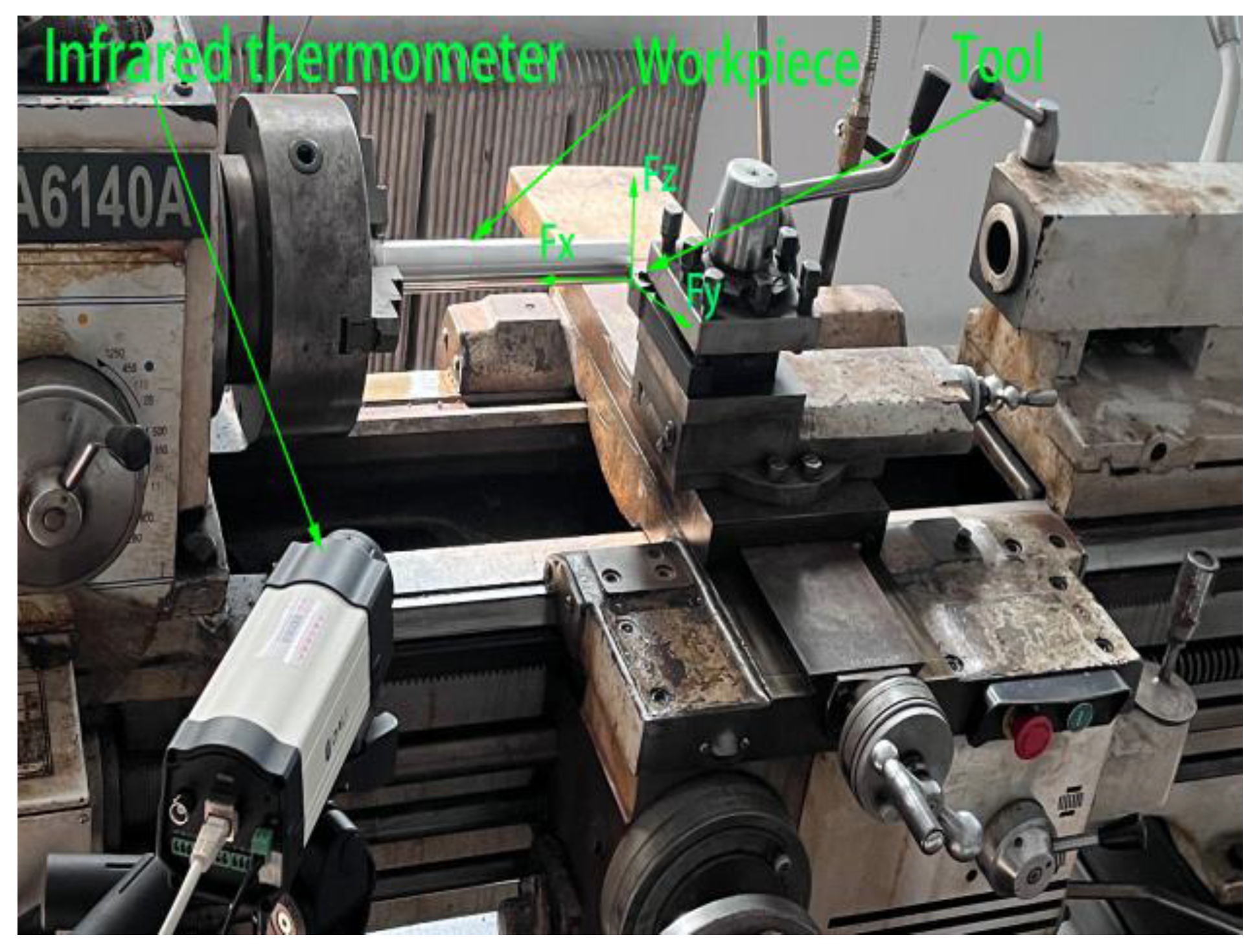
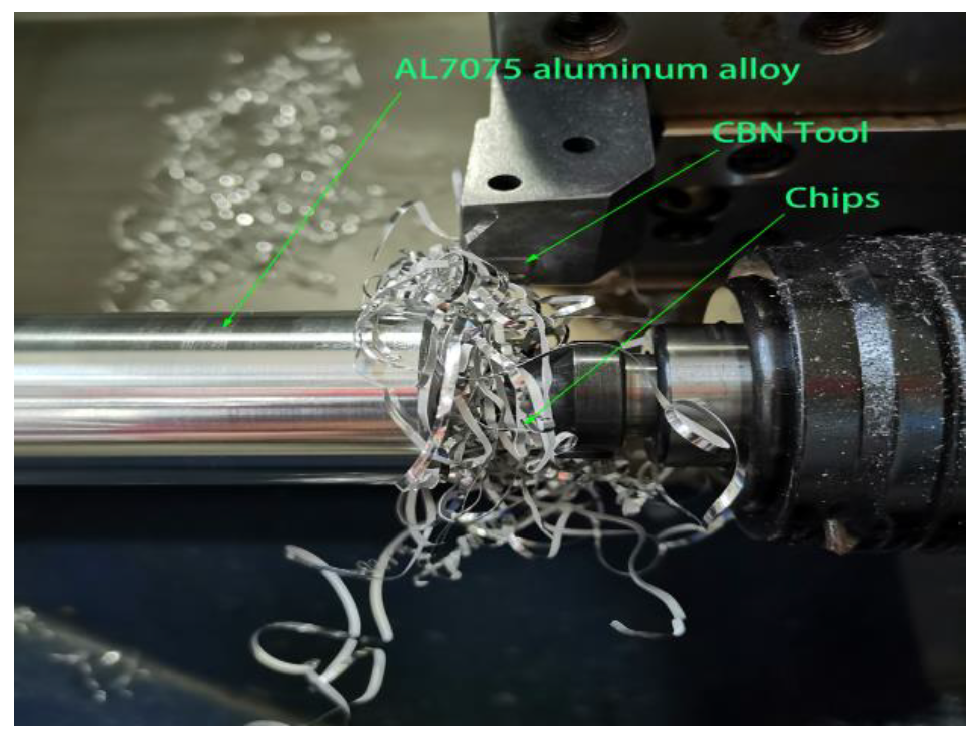
2.1. Test Materials and Equipment

The CBN tool was used in the test. Tool material is a new kind of artificial material, which is widely used in the cutting industry because of its high hardness and good impact resistance [19,20]. Tool material performance parameters are shown in Table 1. The workpiece material is made of AL7075 aluminum alloy, 50 mm in diameter and 250 mm in length. The performance parameters of workpiece materials are shown in Table 2. The cutting force data were collected by CA6140A lathe and Kistler 2825A-02 high sensitivity piezoelectric three-way dynamometer. Thermal imagers are used to measure the cutting temperature produced during the cutting process. The test equipment is shown in Figure 1.

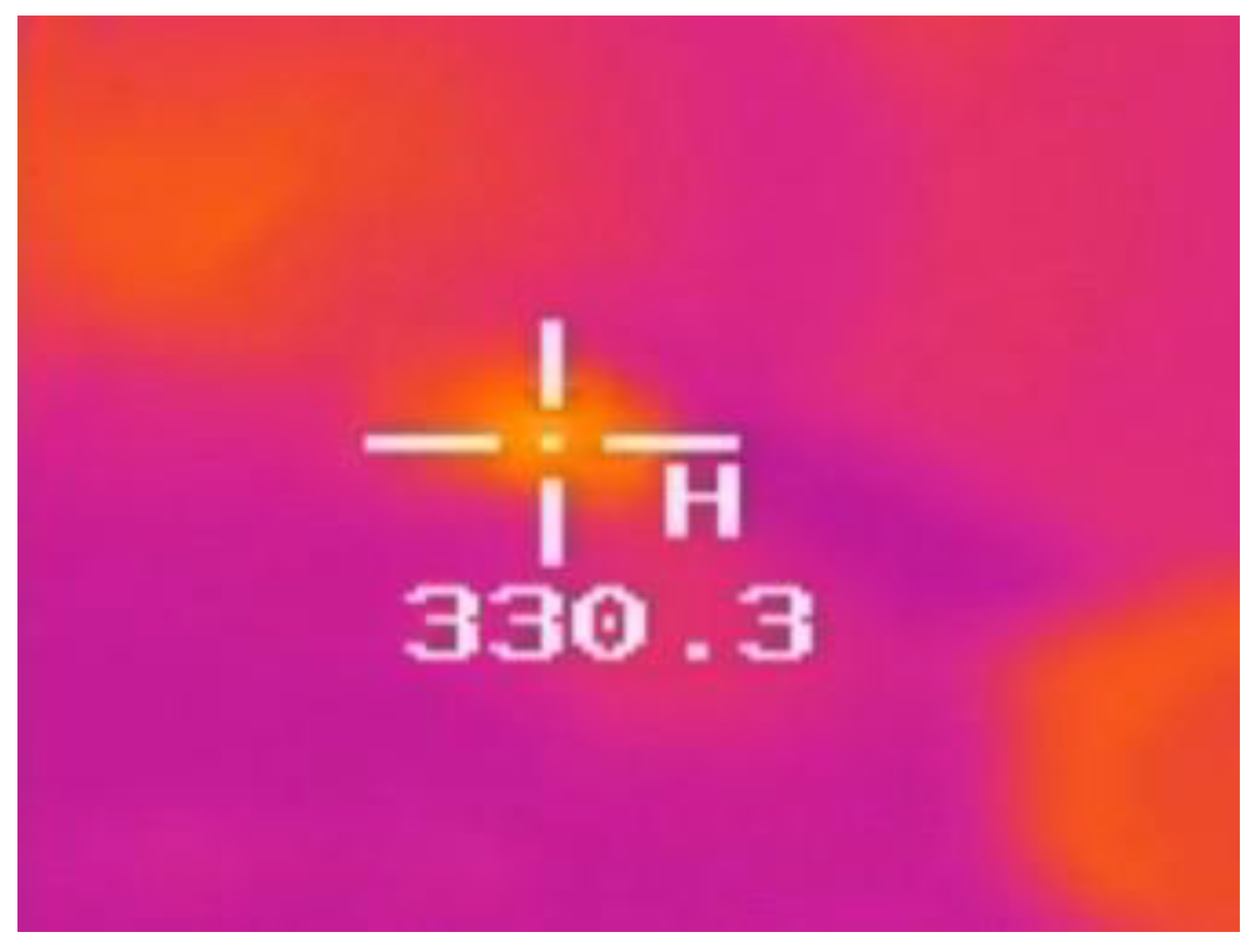
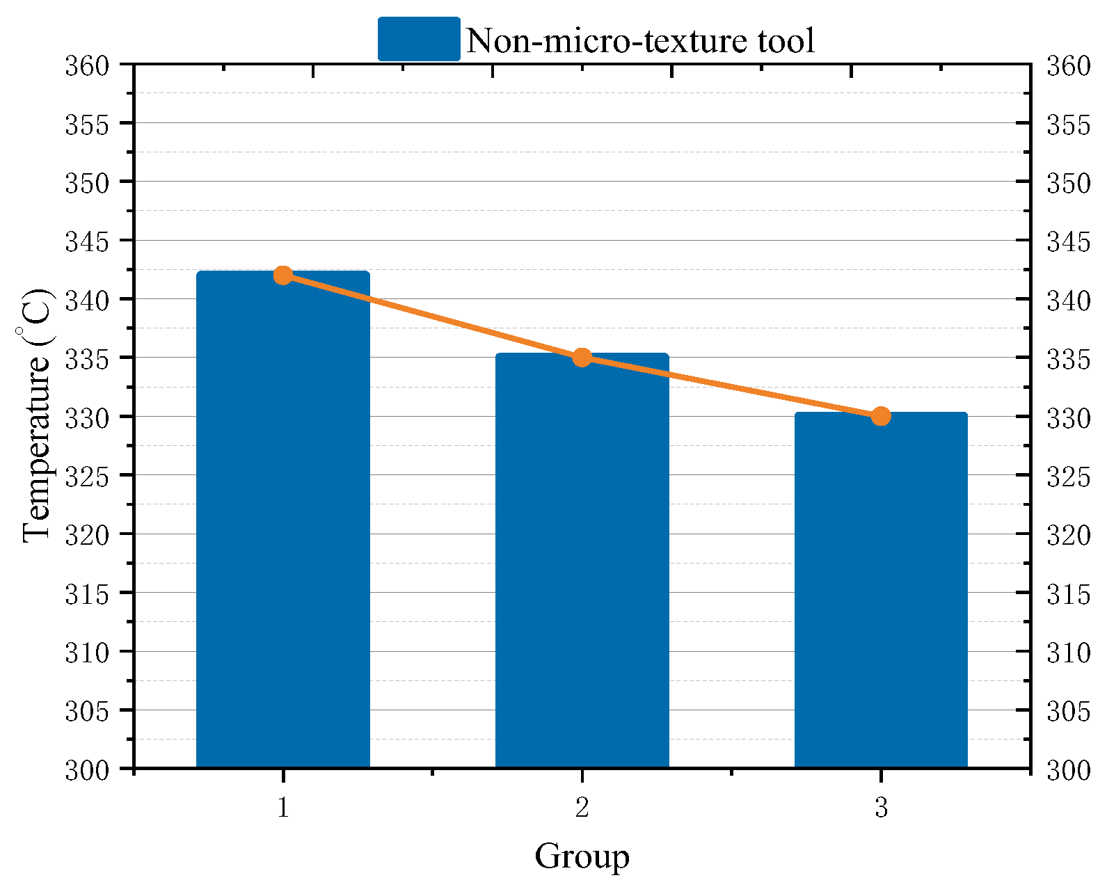
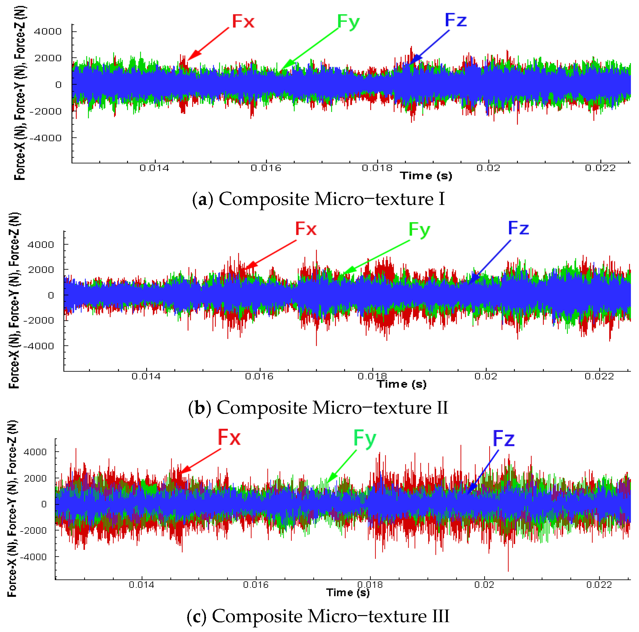
2.2. Cutting Test and Result

In the cutting process, the selection of cutting amount has an important influence on the generation of cutting heat and the stability of the cutting process [23]. In this paper, the cutting test scheme shown in Table 3 is designed according to the suitable machining parameter range of CBN tool and the guarantee of machining accuracy. Dry cutting is used in the cutting test.
The cutting force test results are shown in Figure 2 below. As the cutting speed decreases, the cutting force decreases gradually. When the cutting parameters are Vc = 125 m/min, f = 0.2 mm/r, ap = 0.3 mm, the cutting force is the smallest. This is because with the decrease of cutting amount, the shape and size of cutting layer decrease, the shape deformation of workpiece decreases, leading to the decrease in cutting force. As Figure 3 shows, the chip entanglement around the aluminum alloy rod, even without spilling and stacking near the main edge of the cutter, increasing the length of the chip’s contact with the tool and producing it prone to psoriasis.
Figure 4 shows data collected using a thermal imager, and Figure 5 shows the results of the cutting temperature test. It can be seen from the graph that the cutting temperature decreases with the cutting quantity, and the cutting deformation, friction and contact area decrease with the cutting quantity, which improves the heat dissipation conditions and promotes further heat dissipation of the tool.

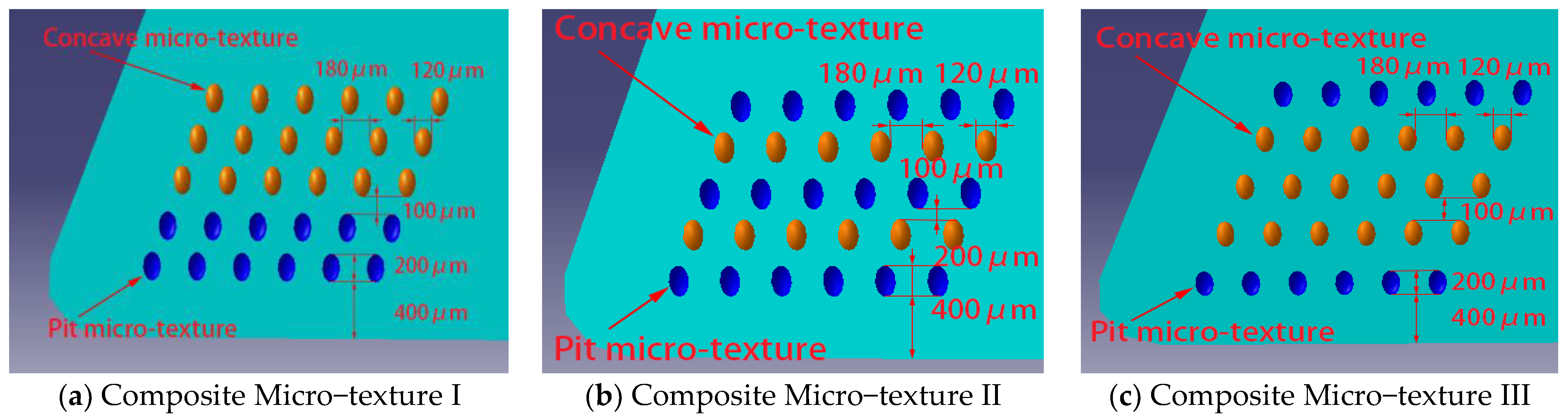
3. Cutting Simulation Test of Composite Micro–Textured Tool

In view of the difficulty of aluminum alloy material processing, CBN tool is difficult to cut aluminum alloy material chips under conventional cutting conditions [24,25]. On the basis of using single micro–texture to improve tool performance, the concept of composite micro–texture tool is proposed. Using the synergy of concave micro–texture and convex micro–texture, the tool performance is further improved.

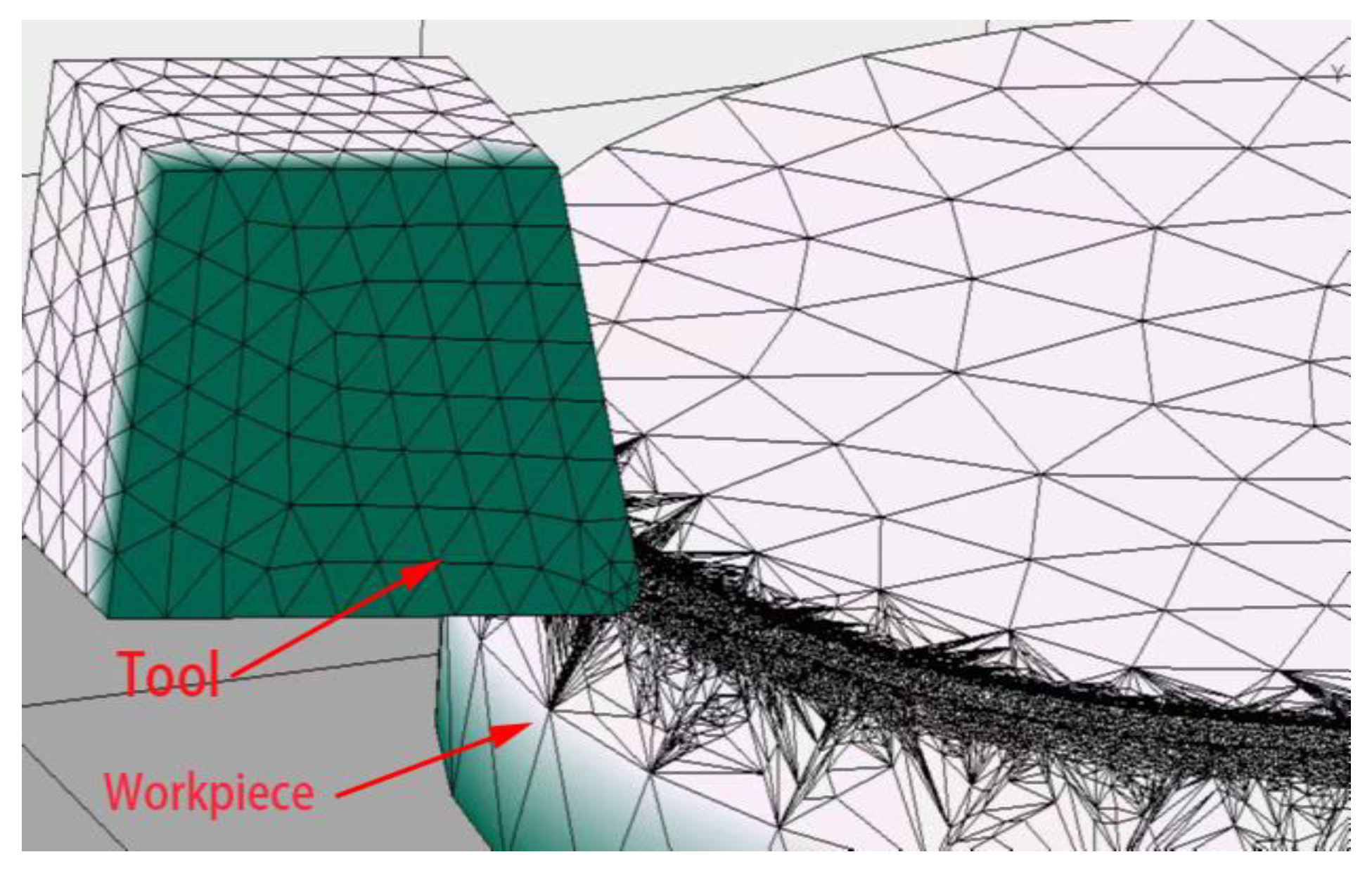
3.1. Finite Element Simulation

In order to study the effect of pitching and pitching microstructure on tool cutting performance, three kinds of composite micro–texture tools are designed in this paper, which are shown in Figure 6. Composite micro–texture two-tool (micro–texture combination with pit and then convex interlaced according to main cutting edge); composite micro–texture e III (a combination of three rows of micro–textures protruding from a pit first and then, based on the main cutting edge). Pit micro–texture depth 35 μm. Height of convex micro–textured tool 35 μm.
The above three composite micro–texture models are imported into the finite element simulation software, and the tool and workpiece are meshed. The maximum mesh size of the tool is set to 1 mm, the minimum mesh size is set to 0.1 mm, the maximum mesh size of the workpiece is set to 3 mm, and the minimum mesh size is set to 0.1 mm. The finite element simulation mesh model of the tool workpiece is shown in Figure 7. The cutting amount scheme selects the minimum cutting amount combination of the above cutting forces, namely Vc = 125 m/min, f = 0.2 mm/r, ap = 0.3 mm.
In the finite element analysis, the Johnson–Cook constitutive model is selected. The model shows that the strain, strain rate and temperature distribution are not uniform and vary greatly when the materials collide. It can accurately reflect the large strain and thermal softening effect of the materials in the cutting process. The parameters of the constitutive model are shown in Table 4 [26,27].
Empirical equation of Johnson-Cook constitutive model:
σ = [ A + B ( ε ) n ] [ 1 + C ln ( ε p ε ˙ 0 ) ] { 1 ( t t 0 t m t 0 ) m }
where: σ—Plastic stress, A—yield strength, B—strain hardening constant; C—strain rate hardening coefficient, m—thermal softening parameter, n—strain hardening parameter; ε—Plastic strain, ε ˙ p—plastic strain rate, ε ˙ 0—reference strain rate; t—material dynamic temperature, t0—ambient reference temperature, tm—material melting point.

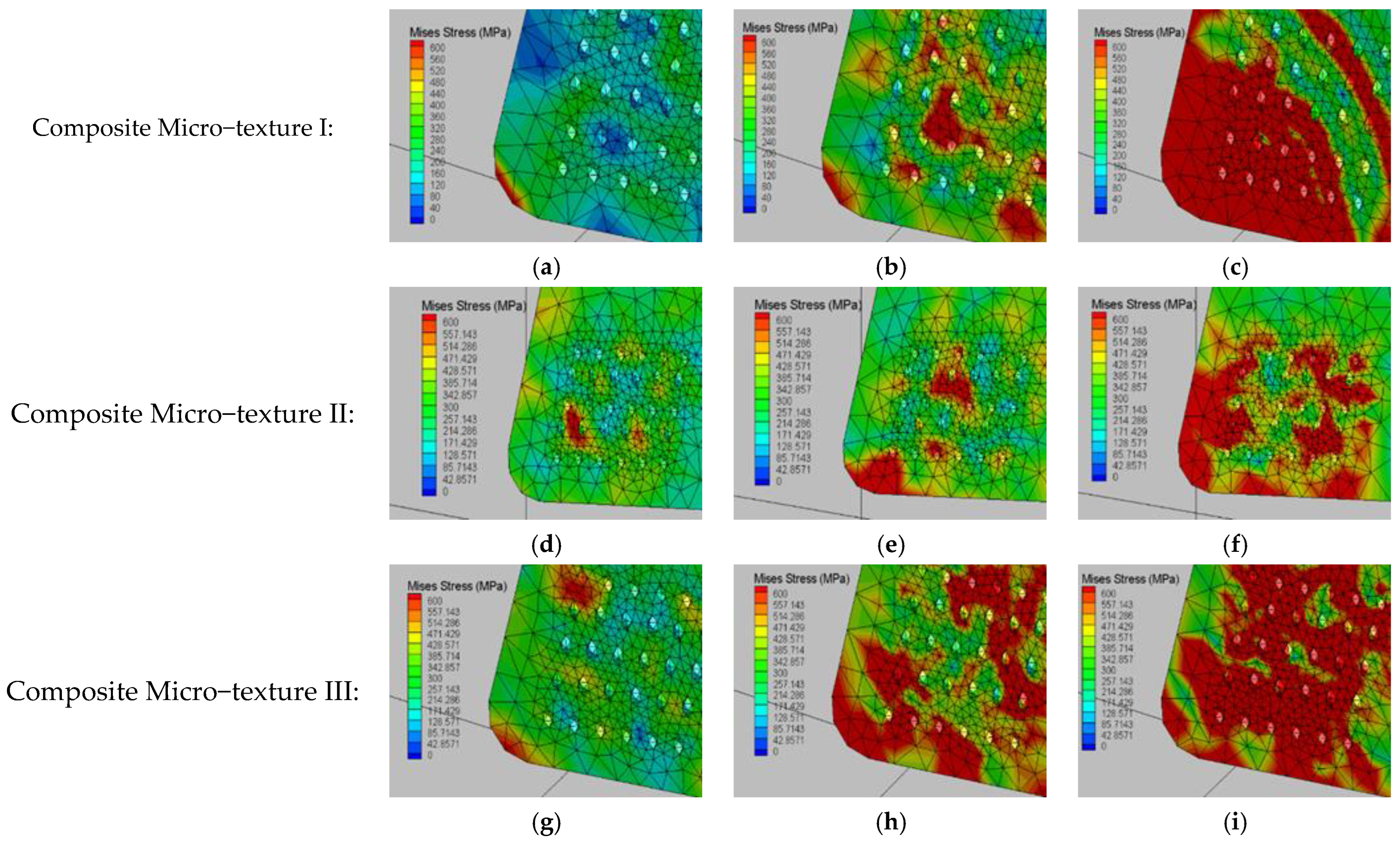
3.2. Analysis of Simulation Results

3.2.1. Effect of Composite Microtextured Tool on Chip

Under the same cutting amount, the cutting simulation test of the three composite micro–texturing tools is carried out to obtain the chip morphology as shown in Figure 8 and the cutting temperature as shown in Figure 9. It is found in observation Figure 8 that when cutting with three tools, composite micro–texture I and composite micro–texture III, continuous strip chips are formed and curl out on the front of the blade. When working with a composite micro–texture two-tool, the chip is partially broken and spilled at the front of the cutter.
During cutting process, the cutting-edge part of the tool collides with the cutting material, the cutting layer of the tool is subjected to shear stress, which causes the cutting chips to form and flow out along the front of the tool and be rubbed by the front of the tool. Composite micro–texture two tools, because of the dented and crisscrossed composite micro–texture, when the chip flows through the part of the composite micro–texture, it causes extrusion and friction, which leads to a decrease in the curl radius of the chip, an increase in strain of the chip material and a fracture of the chip.
As can be seen from Figure 9, the lowest cutting temperature was obtained when using a composite micro–texture II tool. Compared to the same cutting conditions, the reduction in the micro–texture I, II and III tools was 7.27%, 9.09% and 3.64%. It is very easy to cause the workpiece material to be softened by heat, produce thermal deformation, attach to tool surface, and affect machining. The distribution of cutting temperature is mainly taken away by chip fracture and overflow, and the closer the chip meets the tool surface, the less heat can be dissipated. For the composite micro–texture of the two tools, most of the heat of chip breaking is taken away with chip breaking, and the contact area between knife and chip is reduced, the contact surface friction is reduced, and the heat dissipation is lost, so the cutting temperature is reduced.

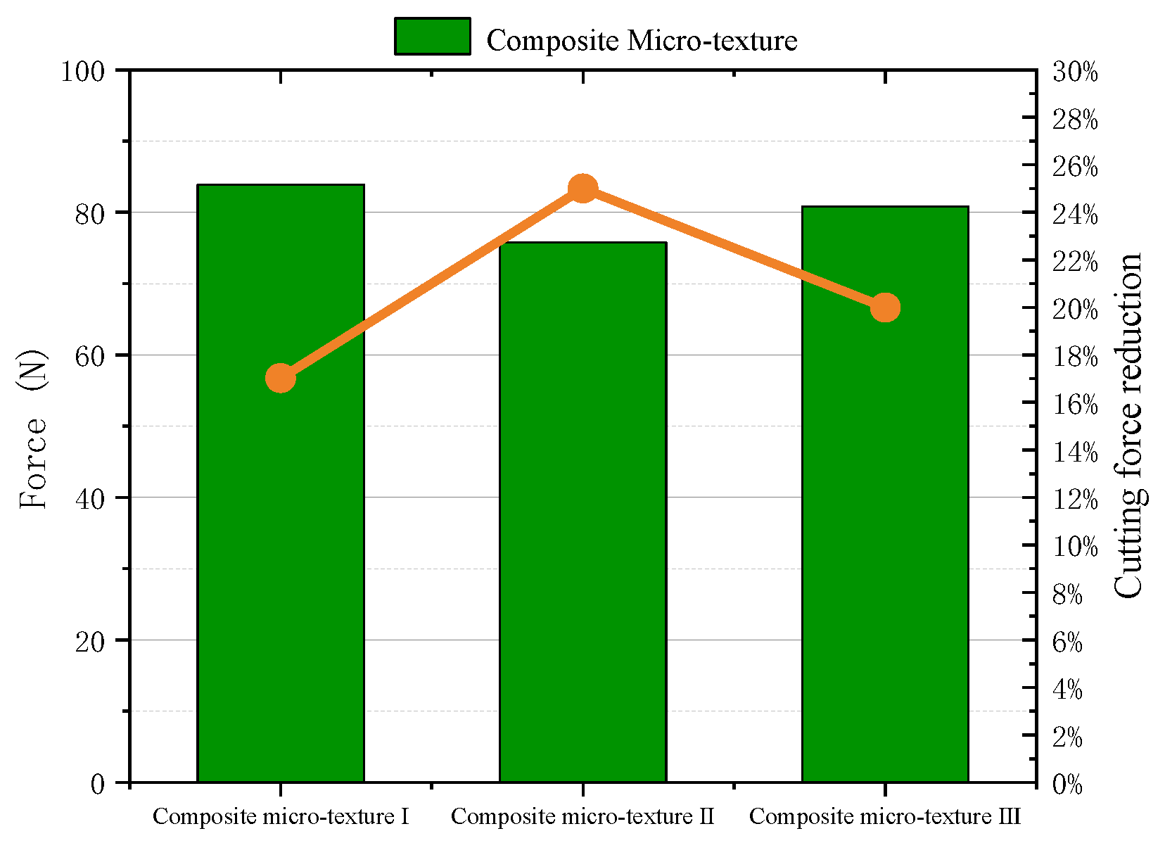
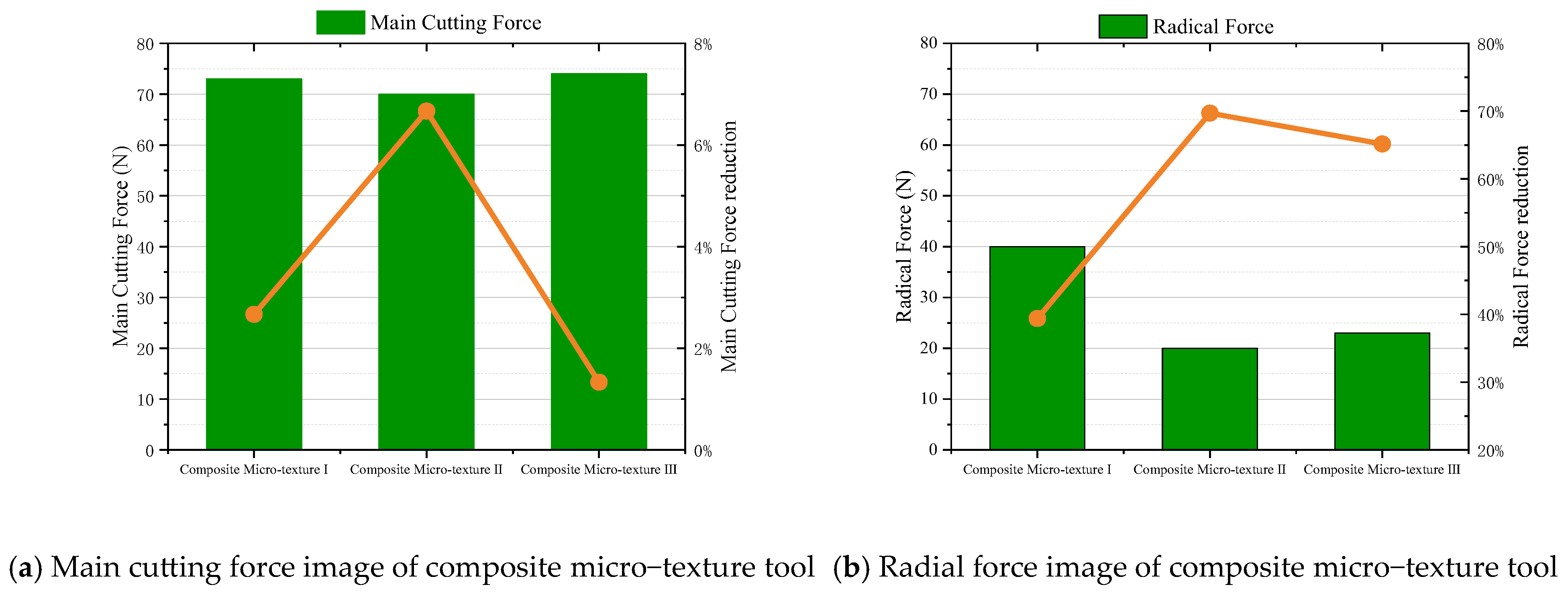
3.2.2. Effect of Composite Micro–Textured Tool on Cutting Force

Collect the data of cutting force test results. To avoid errors due to the randomness of data collection, multiple data points were uniformly selected during the cutting process and their averages were calculated as cutting force test results, Figure 10 shows the mechanical fluctuation of the cutting force during simulation test and Figure 11 shows the result of cutting force test.
As can be seen from Figure 11, the cutting force of the three composite micro–textured tools decreased by 17.02%, 25% and 19.99%, respectively, compared to non-microstructural tools. On the one hand, because of the compound micro–texture on the rake tooth surface, the actual contact length with the chip is reduced, the friction coefficient is reduced and the friction force is reduced; on the other hand, the dent-convex micro–texture increases the extrusion degree the tool structure in the cutting layer of the workpiece material and reduces friction force. The composite micro–texture II tool has the greatest influence on the reduction in cutting force. This is because when cutting with the composite micro–texture II tool, the chips break and spill, and do not accumulate and clog at the tool tip, reducing secondary cutting and resulting in a reduction in cutting force.
Figure 12 shows a comparison of radial force with and without micro–textured tools. The first is the non-woven cutting test group, the second, third and fourth are the composite micro–textured tools one, II and III. As can be seen from Figure 8, the influence of three kinds of composite microstructure tools on the radial force is very significant. The smaller the radial force of the tool, the smaller the radial pulse, the more stable the machining state. It can be seen that composite microstructure tool can improve the stability of the cutting process and improve the quality of cutting products.
Figure 13 is the stress distribution diagram during the cutting process of the composite micro–textured tool. Figure (a,d,c) are the tool stress distribution at the beginning of cutting. (b,e,h) are the tool stress distribution maps for stable cutting; (c,f,i) are the tool stress profiles at the end of the cutting process. It can be seen from the figure that with the cutting process, the stress gradually spreads to the inside of the tool front face and gradually transfers to the micro–textured position. Comparing the stress nephogram of three kinds of composite micro–texture tools, it is found that the secondary stress of composite micro–texture is concentrated at the micro–texture position far away from the tool tip and the main cutting edge, and the stress value is the smallest. It can be concluded that the stress absorption effect of composite micro–texture II is significantly better than that of the other two micro–texture tools.
It can be seen from the above three kinds of composite micro–texture simulation experiments that the chip, cutting force and stress distribution can be significantly improved by using two tools of composite micro–texture combination, namely, the pit-convex interwoven micro–texture combination.

4. Simulation Test of Coated Composite Micro–Textured Tool

During the cutting process, the cutting heat increases rapidly, and the aluminum alloy chips softens easily and adheres to the tool. In the cutting process of aluminum alloy materials, the main cause of tool wear is adhesive wear. In order to further improve the properties of aluminum alloy tool, the concept of coated tools is put forward. Compared with traditional tools, coated tools have higher abrasion resistance and thermal stability, and are now widely used in machining [29,30]. In this paper, the coating is combined with composite microstructure tool to optimize the cutting performance of aluminum alloy.

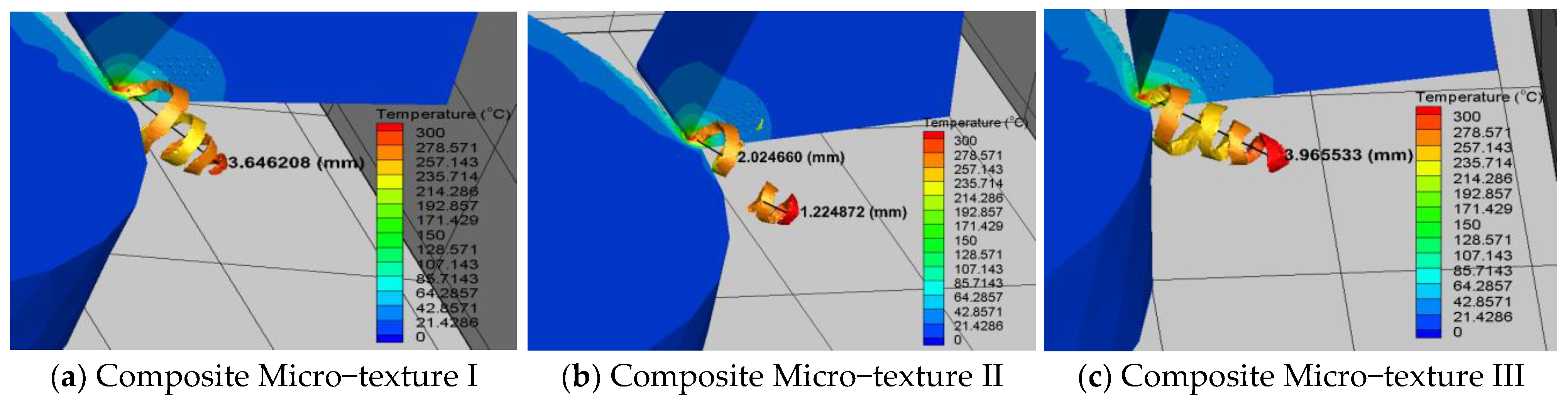
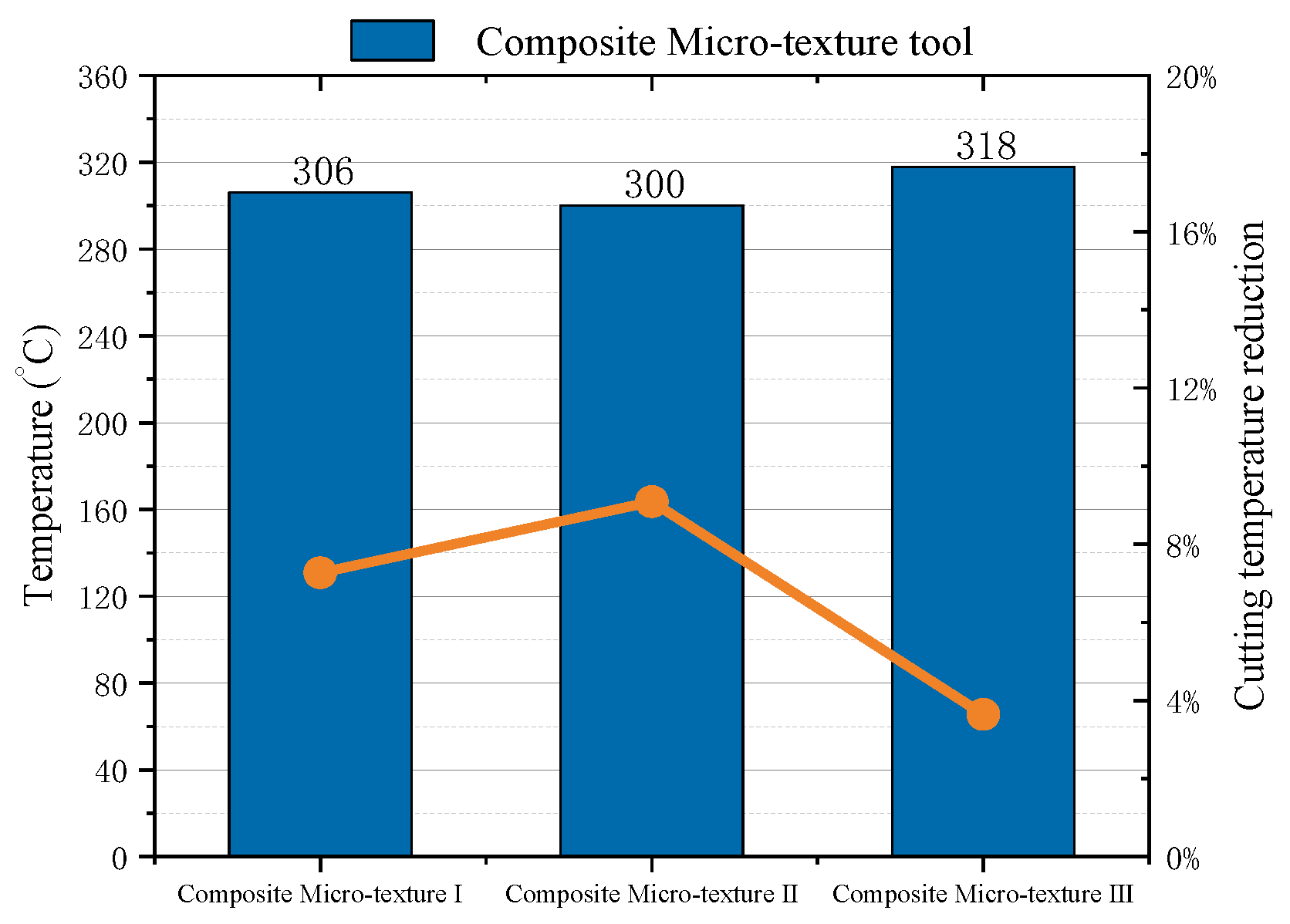
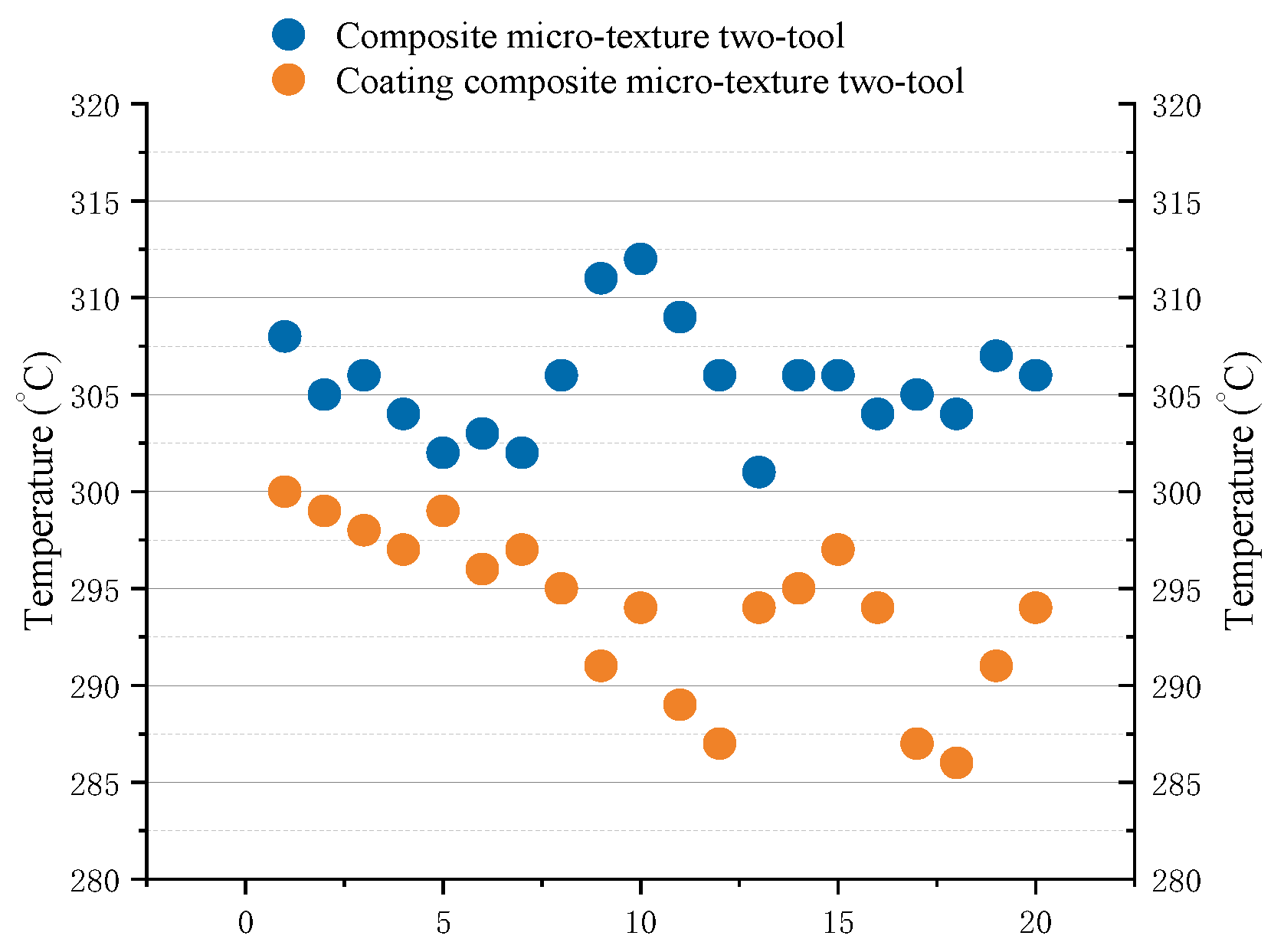
4.1. Effect of Coated Micro–Textured Tools on Cutting Temperature

TiN material micron was coated on the surface of the above selected composite micro–texture II tool 1.5μm and the cutting force is tested with minimum cutting dosage. Figure 14 shows a comparison of cutting temperatures between coated and uncoated micro–textured tools. It can be seen from the figure that the cutting temperature of coated tools is about 3% lower than that of uncoated tools. When using coated microstructure tool to process aluminum alloy material, TiN material clings to tool surface, TiN material coated on tool surface acts as thermal protective film, which reduces friction coefficient between tool and workpiece, has the effect of dry lubrication, promotes the smooth flow of chip and reduces the heat of cutting due to chip accumulation. Due to the chemical stability of TiN material, it is difficult to react with cutting material under high temperature and pressure, so the tool works well under high temperature.

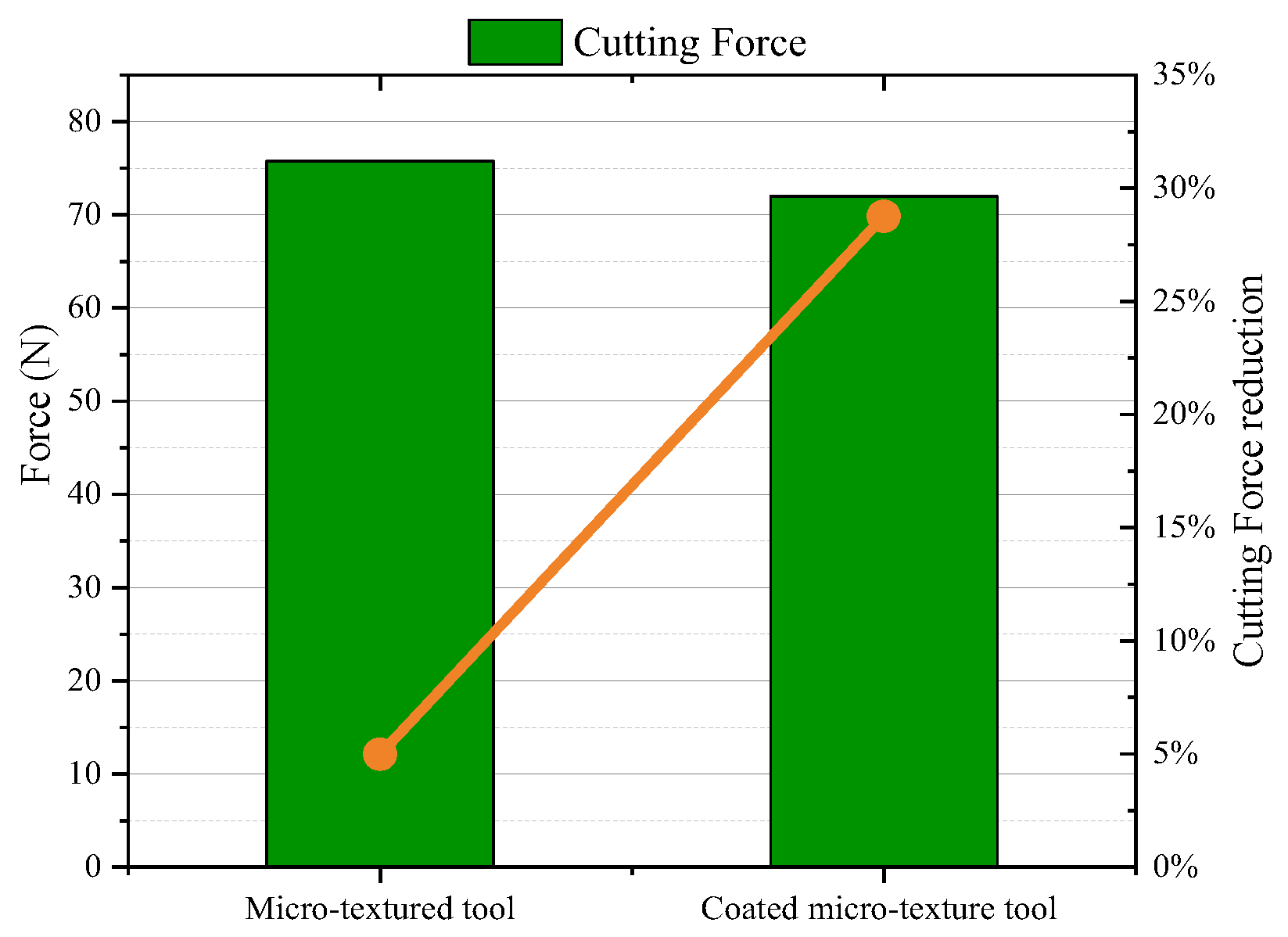
4.2. Effect of Coated Micro–Textured Tool on Cutting Force

Figure 15 shows a decrease of 28.75% in the cutting force of coated and uncoated micro–textured tools and 4.99% in the cutting force of coated and uncoated micro–textured tools. When TiN material works instead of tool body, TiN material acts as barrier, which makes it difficult to invade the chip material produced by external cutting. TiN material has higher hardness and is more abrasive than tool body material, which reduces internal stress and protects tool body structure.
Therefore, coating on the tool surface can alleviate the cutting force and heat produced during the cutting process, and effectively protect the tool. So, it is practical to apply coating technology to tool surface and optimize tool performance based on the optimization of composite microstructure tool.

5. Conclusions

In this paper, the optimal cutting dosage combination is selected by cutting test, taking cutting force and cutting temperature as the yardstick. The cutting performance of the composite micro–texture tool is simulated by means of finite element simulation software combined with the above optimal cutting quantity. By comparing the cutting performance of the different optimal composite micro–texture e tool, the cutting performance of different composite micro–texture tools is optimized, and coating cutting test is carried out on the preferred composite micro–texture tool. The results were as follows:
(1)
Cutting tools with interlaced pit-convex micro–texture promote wafer curl and fracture. When the chip flows through the blade, the fracture overflows and the chip accumulation improves markedly;
(2)
Changes in the distribution of dented tissue in the front of the tool will cause changes in cutting force and cutting temperature. pit-convex micro–texture combined with staggered micro–texture has good cutting performance in reducing cutting force and cutting temperature;
(3)
Due to the high hardness and chemical stability of the coating material, it acts as a protective barrier in the event of sharp tool collisions and further optimizes the cutting performance of the tool;
(4)
The combination of combined micro–texture and surface coating has solved the processing problem of aluminum alloy material chip winding with large fluctuations and provided a theoretical basis for aluminum alloy cutting.

Author Contributions

Q.L. research ideas, experimental design and data analysis are provided; C.M. writing manuscripts, charting, data collection.; L.X. data collection, data analysis, literature retrieval; B.W. document retrieval, data collection, research design.; S.Z. experimental design, data collection, data analysis. All authors have read and agreed to the published version of the manuscript.

Funding

Here, we need to thank the following organizations for their strong support: “Natural Science Foundation of Jilin Province-General Project, Study on the Machinability of Milling Titanium Alloy with Micro–texture Milling Cutter” (20220101227JC).

Data Availability Statement

The data that support the findings of this study are available from the corresponding author upon reasonable request.

Acknowledgments

Authors would like to thank the members of the project team for their dedications and efforts, and the teachers and schools for their help.

Conflicts of Interest

The authors declare no conflict of interest.

References

  1. Debnath, S.; Reddy, M.M.; Yi, Q.S. Environmental friendly cutting fluids and cooling techniques in machining: A review. J. Clean. Prod. 2014, 83, 33–47. [Google Scholar] [CrossRef]
  2. Zhou, Y.; He, Y.Y.; Yang, Z.T.; Yang, J.; Fu, Y.H. The performance of composite texture cutting tool for cutting aluminum alloy. China Surf. Eng. 2022, 35, 281–288. [Google Scholar]
  3. Rambabu, P.P.N.K.V.; Eswara Prasad, N.; Kutumbarao, V.V.; Wanhill, R.J.H. Aluminium alloys for aerospace applications. In Aerospace Materials and Material Technologies; Springer: Singapore, 2017; Volume 1, Aerospace materials; pp. 29–52. [Google Scholar]
  4. Georgantzia, E.; Gkantou, M.; Kamaris, G.S. Aluminium alloys as structural material: A review of research. Eng. Struct. 2021, 227, 111372. [Google Scholar] [CrossRef]
  5. Dong, G.; Wang, X.; Gao, S. Molecular dynamics simulation and experiment research of cutting-tool wear mechanism for cutting aluminum alloy. Int. J. Adv. Manuf. Technol. 2018, 96, 1123–1137. [Google Scholar] [CrossRef]
  6. Sharifi, M.; Akbari, M. Experimental investigation of the effect of process parameters on cutting region temperature and cutting edge quality in laser cutting of AL6061T6 alloy. Optik 2019, 184, 457–463. [Google Scholar] [CrossRef]
  7. Sugihara, T.; Singh, P.; Enomoto, T. Development of novel cutting tools with dimple textured surfaces for dry machining of aluminum alloys. Procedia Manuf. 2017, 14, 111–117. [Google Scholar] [CrossRef]
  8. Liu, W.; Liu, S.; Liang, G.Q.; Yuan, H.C. Simulation analysis of cutting performance and friction reduction effect of micro–textured tools. Surf. Technol. 2022, 51, 338–346. [Google Scholar]
  9. Arulkirubakaran, D.; Senthilkumar, V.; Kumawat, V. Effect of micro–textured tools on machining of Ti–6Al–4V alloy: An experimental and numerical approach. Int. J. Refract. Met. Hard Mater. 2016, 54, 165–177. [Google Scholar] [CrossRef]
  10. Duan, R.; Deng, J.; Lei, S.; Ge, D.; Liu, Y.; Li, X. Effect of derivative cutting on machining performance of micro textured tools. J. Manuf. Process. 2019, 45, 544–556. [Google Scholar] [CrossRef]
  11. Su, Y.; Li, Z.; Li, L.; Wang, J.; Gao, H.; Wang, G. Cutting performance of micro–textured polycrystalline diamond tool in dry cutting. J. Manuf. Process. 2017, 27, 1–7. [Google Scholar] [CrossRef]
  12. Rathod, P.; Aravindan, S. Performance evaluation of novel micro–textured tools in improving the machinability of aluminum alloy (Al 6063). Procedia Technol. 2016, 23, 296–303. [Google Scholar] [CrossRef] [Green Version]
  13. Patel, K.; Liu, G.; Shah, S.R.; Özel, T. Effect of micro–textured tool parameters on forces, stresses, wear rate, and variable friction in titanium alloy machining. J. Manuf. Sci. Eng. 2020, 142, 021007. [Google Scholar] [CrossRef]
  14. Zhang, Y.; Li, Q.H.; Yang, F.S. Modeling and simulation of continuous wear of micro–textured tools. Tool Technol. 2022, 56, 76–81. [Google Scholar]
  15. Fu, Y.H.; Wang, H.B.; Gu, Y.L.; Li, Y.D. Microtexture design and cutting simulation analysis of tool surface. Mach. Manuf. 2016, 54, 5047–5055. [Google Scholar]
  16. Morsy, M.K.; Sharoba, A.M.; Khalaf, H.H.; El-Tanahy, H.H.; Cutter, C.N. Efficacy of antimicrobial pullulan-based coating to improve internal quality and shelf-life of chicken eggs during storage. J. Food Sci. 2015, 80, M1066–M1074. [Google Scholar] [CrossRef]
  17. Zheng, G.; Zhao, G.; Cheng, X.; Xu, R.; Zhao, J.; Zhang, H. Frictional and wear performance of TiAlN/TiN coated tool against high-strength steel. Ceram. Int. 2018, 44, 6878–6885. [Google Scholar] [CrossRef]
  18. Li, Y.; Zheng, G.; Zhang, X.; Cheng, X.; Yang, X.; Xu, R. Cutting force, tool wear and surface roughness in high-speed milling of high-strength steel with coated tools. J. Mech. Sci. Technol. 2019, 33, 5393–5398. [Google Scholar] [CrossRef]
  19. Rajasekaran, T.; Palanikumar, K.; Vinayagam, B.K. Application of fuzzy logic for modeling surface roughness in turning CFRP composites using CBN tool. Prod. Eng. 2011, 5, 191–199. [Google Scholar] [CrossRef]
  20. Harto, B.; Umroh, B.; Darianto, D. Study on the CBN Tool Wear Mechanism on Dry High-Rate Turning Process for AISI 4140. J. Mech. Eng. Manuf. Mater. Energy 2018, 2, 20–26. [Google Scholar] [CrossRef]
  21. Ślusarczyk, Ł.; Struzikiewicz, G. Hardened steel turning by means of modern CBN cutting tools. In Key Engineering Materials; Trans Tech Publications Ltd.: Baech, Switzerland, 2014; Volume 581, pp. 188–193. [Google Scholar]
  22. Liu, P.; Hu, J.Y.; Li, H.X.; Sun, S.Y.; Zhang, Y.B. Effect of heat treatment on microstructure, hardness and corrosion resistance of 7075 Al alloys fabricated by SLM. J. Manuf. Process. 2020, 60, 578–585. [Google Scholar] [CrossRef]
  23. Rao, C.J.; Rao, D.N.; Srihari, P. Influence of cutting parameters on cutting force and surface finish in turning operation. Procedia Eng. 2013, 64, 1405–1415. [Google Scholar] [CrossRef] [Green Version]
  24. Qi, K.F.; Zhang, C.T.; Zhao, C.X. Research Status and Prospect of Microtexture Tools. Mech. Eng. 2021, 82, 77–78. [Google Scholar]
  25. Viana, F.; Pinto, A.M.P.; Santos, H.M.C.; Lopes, A.B. Retrogression and re-ageing of 7075 aluminium alloy: Microstructural characterization. J. Mater. Process. Technol. 1999, 92, 54–59. [Google Scholar] [CrossRef] [Green Version]
  26. Fan, L.; Deng, Z.; He, Y.; Zhu, X.L.; Gao, X.J.; Jin, Z. The effects of micro–texture shape on serrated chip geometry in the hardened steel AISI D2 cutting process. Surf. Topogr. Metrol. Prop. 2022, 10, 015031. [Google Scholar] [CrossRef]
  27. Chen, W.L.; Yang, D.; Wu, M.; Ma, H.Q. Simulation Study on Right-Angle Cutting of 7050-T7451 Aluminum Alloy. Mach. Manuf. 2021, 59, 63–67. [Google Scholar] [CrossRef]
  28. Peng, H.B.; Zhang, H.J. Research progress of constitutive model of metal materials. Mech. Eng. Mater. 2012, 36, 5–10+75. [Google Scholar]
  29. Cai, F.; Wang, J.; Zhou, Q.; Zhang, S.; Zheng, J.; Wang, Q.; Kim, K.H. Reduced delamination and improved cutting performance of TiAlSiN multilayer coated cutter by tailoring the adhesion layers and intermediate layers. Wear 2022, 488, 204135. [Google Scholar] [CrossRef]
  30. Sadiq, S.N.; Raguraman, T.R.; Kumar, D.T.; Rajasekaran, R.; Kannan, T.T.M. Optimization of milling parameters of OHNS steel using TiAlN coated cutter by design of experiment technique. Int. J. Mech. Eng. Robot. Reearch 2014, 3, 1. [Google Scholar]
Figure 1. Test equipment diagram.
Machines 11 00439 g001
Figure 2. Cutting force of non-micro–textured tool.
Machines 11 00439 g002
Figure 3. Chip winding.
Machines 11 00439 g003
Figure 4. Cutting temperature thermal imaging.
Machines 11 00439 g004
Figure 5. Cutting temperature of non-micro–texture tool.
Machines 11 00439 g005
Figure 6. Micro–texture simulation mode.
Machines 11 00439 g006
Figure 7. Finite element simulation model.
Machines 11 00439 g007
Figure 8. Chip morphology of three composite micro–textured tools.
Machines 11 00439 g008
Figure 9. Cutting temperature of three kinds of composite micro–texture tools.
Machines 11 00439 g009
Figure 10. Mechanical wave diagram of cutting force of three kinds of composite micro–texture tools.
Machines 11 00439 g010
Figure 11. Cutting force of composite micro–texture tool.
Machines 11 00439 g011
Figure 12. Comparison of main cutting force and radial force.
Machines 11 00439 g012
Figure 13. Stress distribution of three kinds of composite micro–texture tool.
Machines 11 00439 g013
Figure 14. Comparison of cutting temperature of coated and non-micro–textured tools.
Machines 11 00439 g014
Figure 15. Comparison of cutting force of coated and uncoated tools.
Machines 11 00439 g015
Table 1. CBN tool material performance parameters [21].
Material
Properties
Young’s Modulus
(Gpa)
Thermal
Conductivity
(W/m·K)
Poisson
Ratio
Density
(g/cm3)
Specific Heat
(J/kg °C)
value6901200.23.8700
Table 2. 7075AL aluminum alloy material performance parameters [22].
Material
Properties
Young’s Modulus (Gpa)Thermal Conductivity
(W/m·K)
Poisson
Ratio
Density
(g/cm3)
Specific Heat
(J/kg·°C)
value71.71730.332.810860
Table 3. Cutting Test Scheme.
GroupCutting Speed Vc (m/min)Feed f (mm/r)Cutting Depth ap (mm)
11900.20.3
21500.20.3
31250.20.3
Table 4. Johnson-Cook constitutive model parameters of 7075AL aluminum alloy [28].
A (MPa)B (MPa)Cnmt0·(°C)tm·(°C)
5466780.0240.711.5620650
Disclaimer/Publisher’s Note: The statements, opinions and data contained in all publications are solely those of the individual author(s) and contributor(s) and not of MDPI and/or the editor(s). MDPI and/or the editor(s) disclaim responsibility for any injury to people or property resulting from any ideas, methods, instructions or products referred to in the content.

