
Design and Experiment of Apple Foam Net Sleeve Packaging Machine with Posture Adjustment Function
by
 , ,
, ,
Shisheng He
1,
Qun Sun
1,*,
Quanjin Wang
1,
Zhiqin Liang
1,
Ying Zhao
1,
Xiuhao Yu
1 and
Haigang Xu
2 1
School of Mechanical and Automotive Engineering, Liaocheng University, Liaocheng 252059, China
2
Shandong Shifeng (Group) Company Ltd., Liaocheng 252899, China
*
Author to whom correspondence should be addressed.
Machines 2023, 11(4), 436; https://doi.org/10.3390/machines11040436
Submission received: 14 February 2023
/
Revised: 18 March 2023
/
Accepted: 26 March 2023
/
Published: 29 March 2023
(This article belongs to the Special Issue New Trends in Robotics and Automation)
Abstract
:Background: In this study, an apple foam net packing machine is designed to improve the efficiency of apple foam net packing, reduce the intensity of manual work, and meet the market demand for diverse forms of apple packing. Methods: Based on the analysis of apple shape characteristics, a secondary posture adjustment method for apples with a vertical posture adjustment mechanism and a side posture adjustment mechanism is proposed. Based on the observation of human hand-set nets and the analysis of the mechanical characteristics of nets, a dual-system net opening method combining a net slackening system and a net opening system is proposed. Results: The experiment shows that: the apple foam net sleeve packing machine can reach 99% of the apple’s posture adjustment rate, the net opening rate can reach 99%, and the packing rate can reach 98.10%. The packing speed is 10 s/pcs, and the packing efficiency is 355–365 pcs/h. The length of the fused mesh net sleeve is mainly distributed between 138 and 143 mm, which accounts for approximately 80% of the total number of samples. Conclusions: The apples packed by this machine are neatly packaged according to specifications. It can improve the efficiency of apple foam net sleeve packing and replace manual work.
1. Introduction
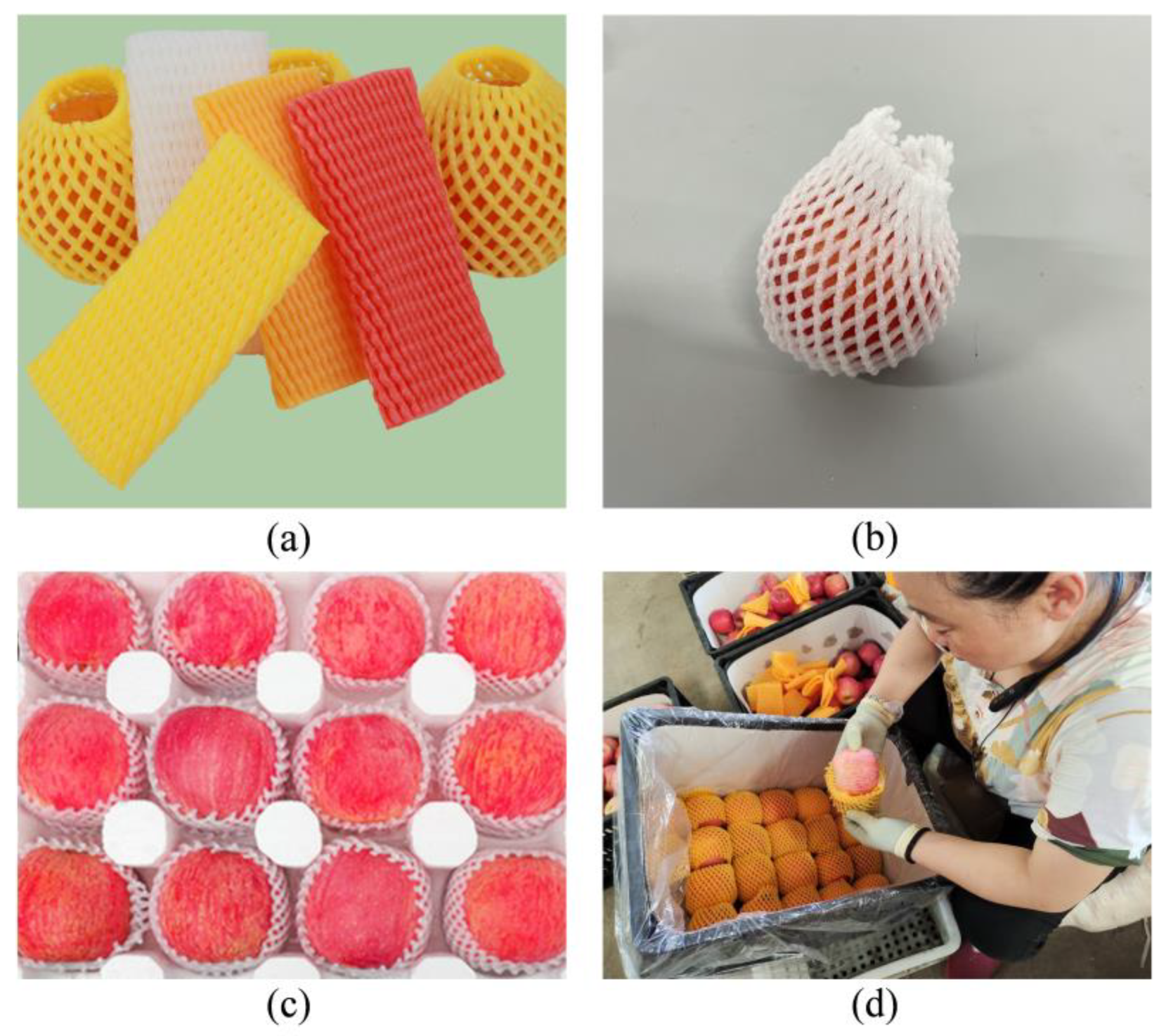
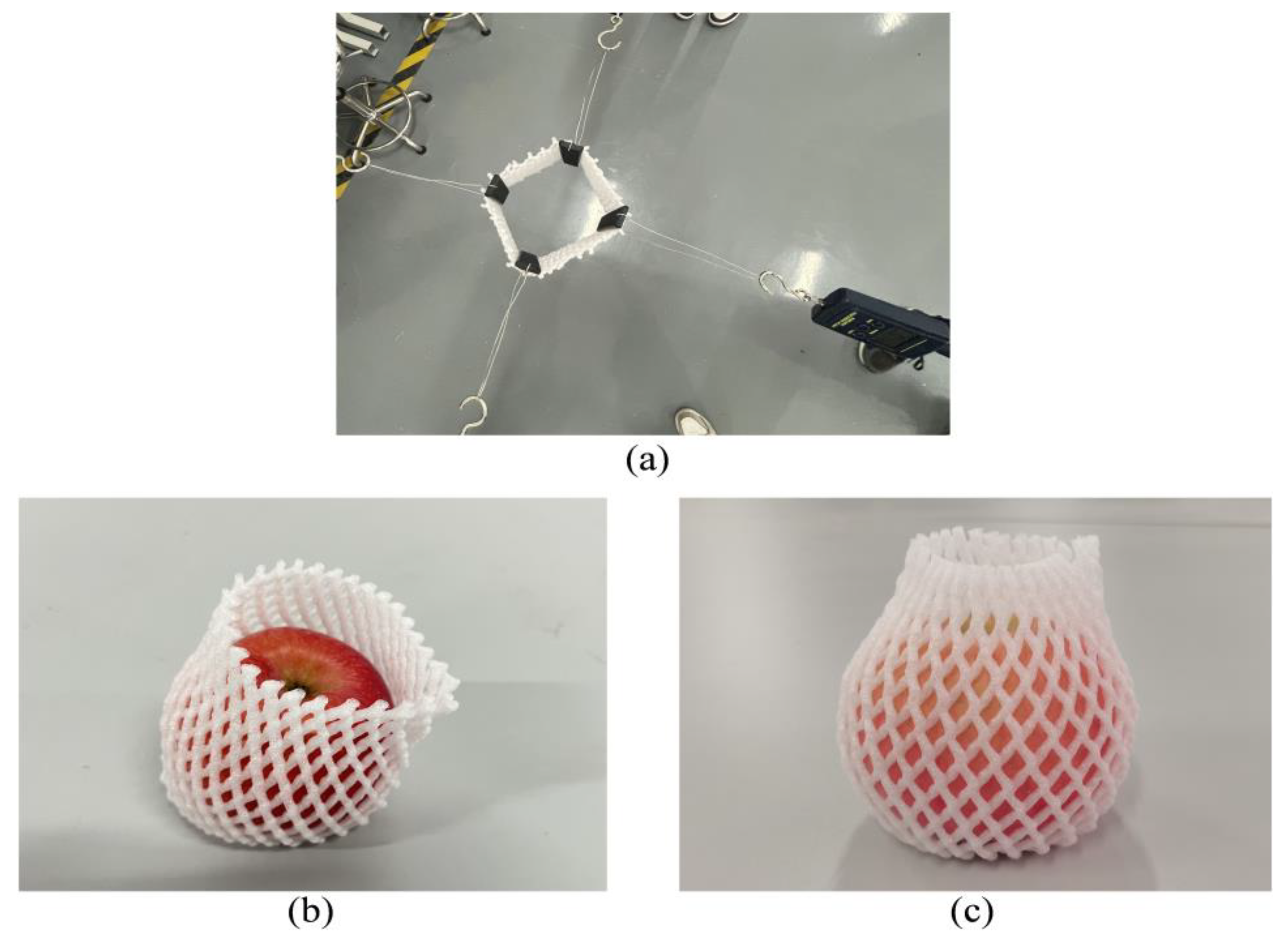
Apples rank second globally in terms of fruit production. China is the world’s largest producer and consumer of apples, accounting for more than 50% of the world’s total apple acreage and production [1,2]. Apples are rich in dietary fiber, phenols, and organic acids [3,4]. It has many health benefits, such as lowering blood pressure, preventing obesity complications, and reducing cardiovascular diseases [5,6]. Global apple production continues to grow and consumption is stable, with fresh consumption of apples accounting for 70–75% of total production [7]. If fresh apples are not well packaged, fresh apples will develop wounds, peel cracks, and other mechanical damage and water loss phenomenon during logistics and handling [8,9]. This can cause apple rot, which affects the appearance of apples and reduces their freshness of apples, resulting in large losses in transportation, storage, and sales, and the loss of the most basic value of apples [10]. Before the apples are boxed, they are covered with a foam mesh sleeve, as shown in Figure 1a. The foam netting is made of polyethylene foam material. Polyethylene foam materials were developed in Europe as early as the 1970s [11,12] and have now become a new environment-friendly packaging material. It has good buffering, high thermal insulation, shock absorption, and certain freshness preservation functions, and is widely used in the field of packaging easily damaged goods, which can be a good way to reduce the problem of transport loss of apples [13,14,15]. At present, there are two ways of apple net sleeve packaging [16]. The first way is the packing method of apple vertical as shown in Figure 1b. That is, the net sleeve completely wrapped the flesh of the apple so that the stem and umbilical end of the apple leaked out slightly. Apples using vertical packaging can maximize the flesh of apples so that they are better protected. The second way is the packing method of the apple sideways, as shown in Figure 1c; that is, the net sleeve completely wraps the stem and navel end of the apple so that the flesh of the apple is exposed. The side of apples allows the apples to be partially exposed all around for easy labeling. After the apples are placed in the store or supermarket, it is easy to display information such as the color of the apples and whether they have defects, which is beautiful and easy for consumers to select. However, the process of apple sleeve net packaging is still dominated by the traditional manual method as shown in Figure 1d. This leads to a low efficiency in apple packaging and inconsistent packaging specifications.
Developed countries have researched fruit, vegetables, and other food processing and packaging machine for a longer period of time, combining advanced technology, personalized packaging forms, and a high degree of intelligence to get results [17,18,19]. Lino Antoni Giefer et al. [20] used convolutional neural networks for automatic localization and pose estimation of camera-captured apples, laying the foundation for the automation of fruit packaging machine systems. Anuja Bhargava et al. [21] developed an automatic grading system based on apple quality to identify defective apples. Nabil S. M. Elkaoud et al. [22] developed a fruit-size sorting machine that can perform sorting operations on fruits such as apples and oranges. Z. Zhang et al. [23] summarized the research progress of mechanical apple harvesting technology and described the current technical bottlenecks and future development trends. M Vallone et al. [24] developed a novel wireless device for real-time mechanical impact assessment in citrus packing lines that allows timely intervention to ensure fruit quality in post-harvest operations. However, because of the different standards and environmental requirements of apple packaging in various countries, no in-depth research has been conducted on apple foam net sleeve packaging machines in developed countries.
Xu Qinchao et al. [25] developed a plastic foam mesh sleeve packaging machine for spherical fruits, which can achieve continuous packaging function for spherical fruits such as apples and navel oranges by using a flexible expanding cone and inverted pricking chuck. However, the packaging machine packaging function is single, which can only achieve irregular packaging of apples, not according to market demand to achieve two different forms of apple vertical and sideways net set packaging. Julie Hu et al. [26] developed automation equipment for apple protect foam net packaging, which used a propping apparatus and electro-mechanical clamps to realize the opening operation of the net sleeve. Hongmei Xia et al. [27] designed an Ordinary Multilayer Fruit Paper Bag Supplying Device for Fruit Bagging, which can continuously take out multilayer fruit paper bags and finish opening them from the inside. With the synchronous driving trajectory and allowable high moving speed, the developed supplying device could achieve more than 90% opening success rate and less than a 2-second opening time. Liu Ruige et al. [28] designed an Automatic Fruit Packing Machine which is compact in size and low-cost to produce. It is powered by a removable battery, can work at any site, and is capable of packing fruit in a net sleeve. However, there is no description related to the principle of net opening, and no specific machine was built. Pan Fan et al. [29] demonstrated the best mode of apple picking, which provides a theoretical basis for further research on apple-picking robots. Wei Ji et al. [30] proposed a variable damping impedance control strategy for gripper grasping force tracking based on the establishment of a contact force model to achieve the compliant grasping of apple harvesting robots and reduce mechanical damage during the process of grasping.
At present, domestic research on foam net sleeve packing machines for apples is still focused on prototype design. For the few existing packaging machines on the market, the net sleeve damage rate is high, and the packaging continuity is low. Therefore, the two net-sleeve packaging methods for apples cannot be packaged, and the packaging specifications are not uniform. In order to solve the above problems, this study designs a multi-functional apple foam net sleeve packaging machine, which can realize two different net sleeve packaging methods for apples to meet the market demand. Meanwhile, it can solve the existing problems of inconsistent apple packaging specifications, the high manufacturing cost of the packaging machine, and the high damage rate of the net sleeve.
2. Foam Net Sleeve Packaging Machine for Apple Composition and Working Principle
Preliminary research (research place: Yantai City, Shandong Province, China) has shown that there are two ways of handling apples picked from fruit trees. The first kind of apple farmers will be picked and stored in cold storage waiting for apple buyers to buy apples, and apple buyers the acquisition of apples will give the apples a set of foam net covers, this way more for small fruit farmers. The second kind of apple will be picked by the farmers themselves to sell or fixed delivery to the fruit retail enterprises, farmers, or enterprises in the sale of apples will be packaged on the foam net cover, and more so for large and medium-sized fruit farmers and fixed orchards. The packaging machine used in this study was an apple foam net sleeve packaging segment.
2.1. Foam Net Sleeve Packaging Machine for Apple Composition
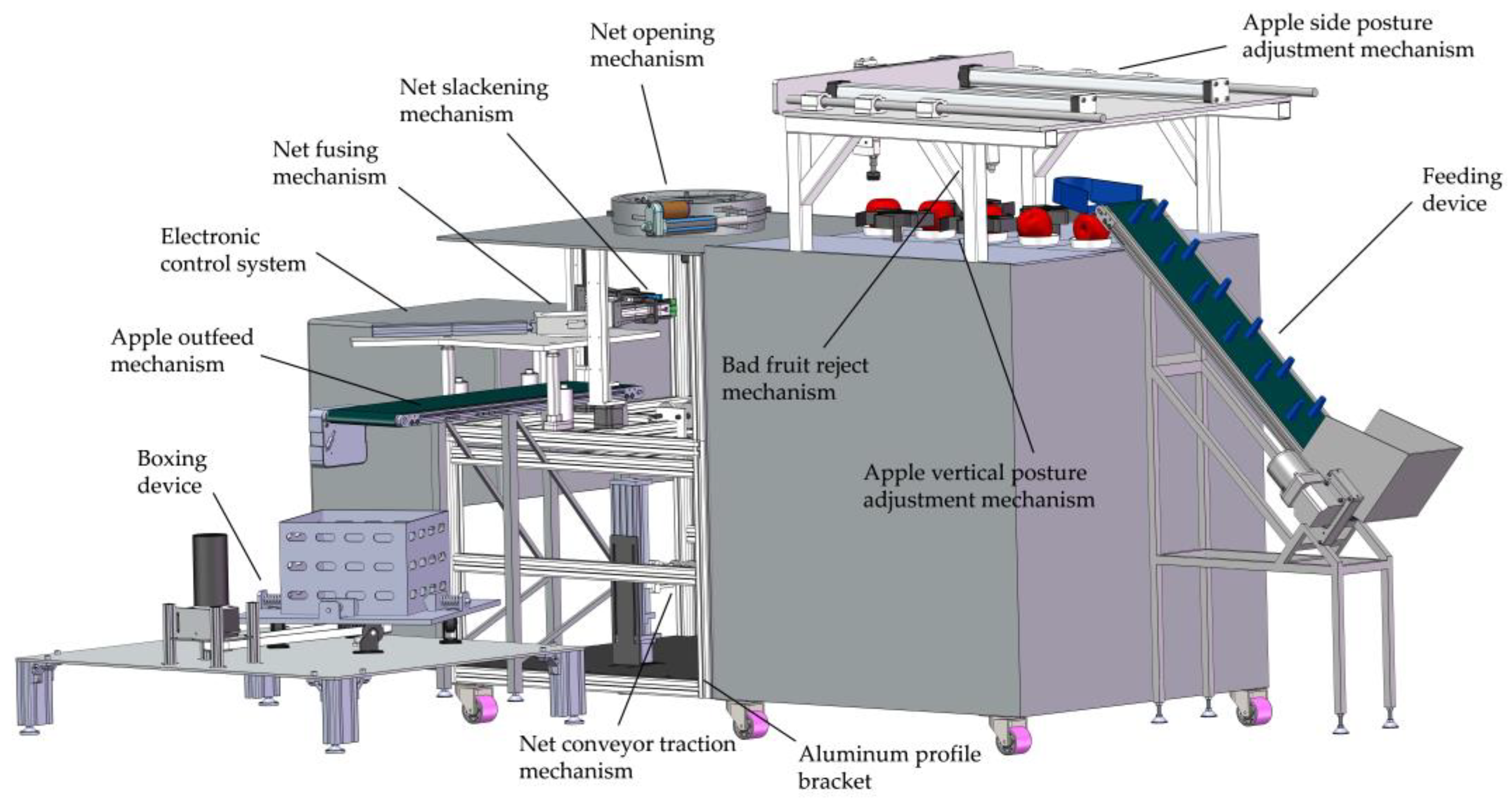
As shown in Figure 2, the overall structure of the apple foam net sleeve packing machine consists of five parts: feeding device, apple posture adjustment device, net device, boxing device, and aluminum profile frame. The apple posture adjustment device includes an apple vertical posture adjustment mechanism and an apple side posture adjustment mechanism. The vertical posture adjustment mechanism is located in the center of the right frame and is used to adjust the posture of the apple for vertical placement. The side posture adjustment mechanism is located at the top of the right frame to adjust the side posture of the apple in the vertical posture. The net device includes a net slackening mechanism, opening mechanism, fusing mechanism, and traction conveying mechanism for net sleeve operation on apples. The net slackening mechanism is located at the center of the frame for the initial slackening and lifting of the net sleeve. The opening mechanism is located at the uppermost part of the frame and is used to open the net sleeve finally. The fusing mechanism is located at the right front of the frame and is used to fuse the net sleeve. The traction mechanism is located at the bottom of the frame to store the net sleeve and to pull the net sleeve back to the initial state after one working cycle. The packaging machine adopts STM32 as the core control chip, using a combination of pneumatic and electric power supply and through the action of the pneumatic circuit to make the net slack fingers, net open fingers, and various pneumatic actuators to achieve the purpose of clamping, opening, extending and returning. The main technical parameters of the apple foam net sleeve packaging machine are shown in Table 1.
2.2. Foam Net Sleeve Packaging Machine for Apple Working Principle
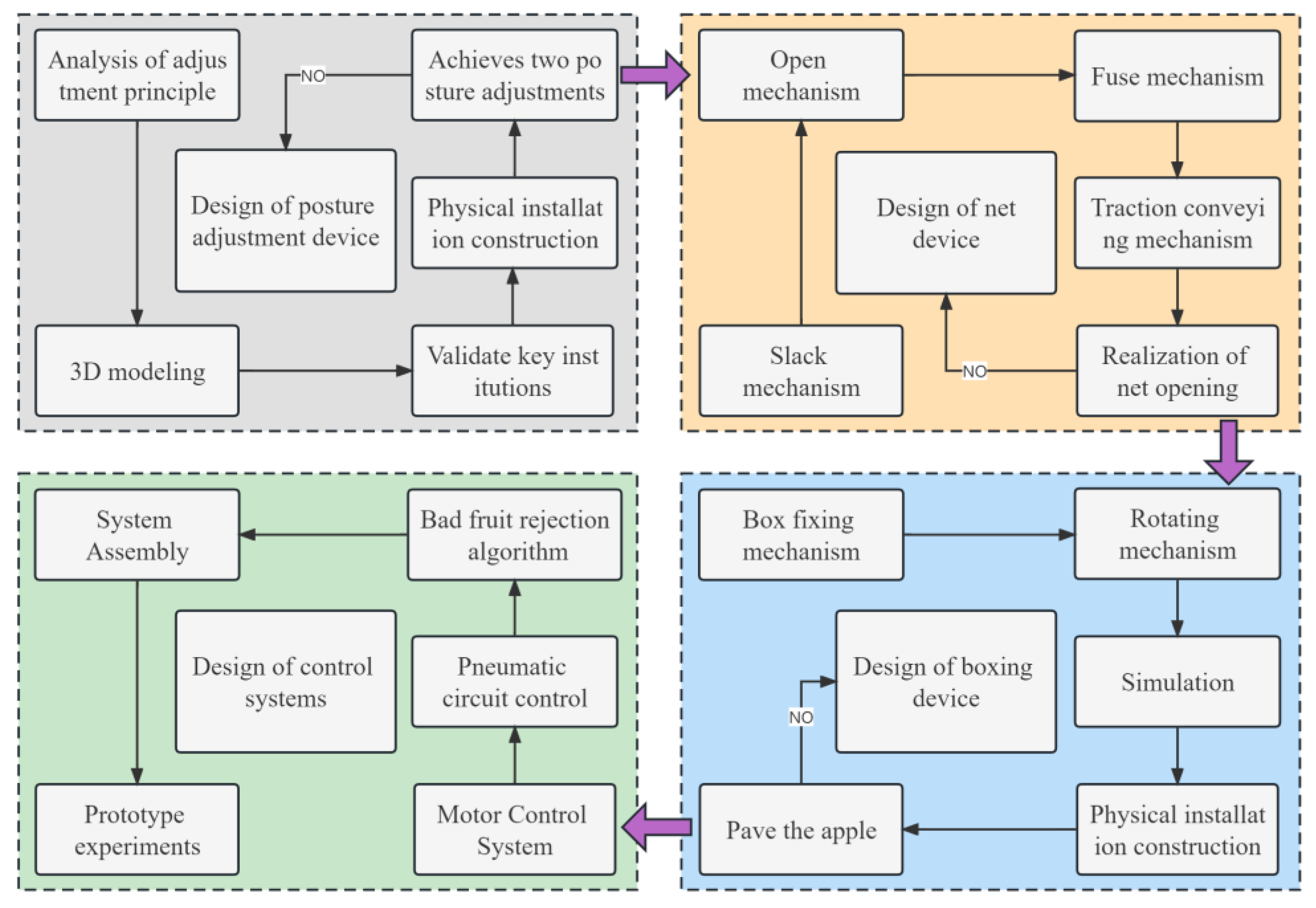
Design the apple foam net sleeve packaging machine according to the design principle in Figure 3. In the initial state of the apple foam sleeve packaging machine, the net sleeve slackening finger is in the lower stop position, the traction finger is in the upper stop position, and the net opening mechanism is in the closed state. Before the machine starts to work, the non-cutting foam net sleeve is firstly wound by hand on the net sleeve storage tray of the traction conveying mechanism then the work object apple is put into the hopper of the feeding device and one end of the net sleeve is transported to the initial position through the guide roller and the traction roller. Turning on the machine through the control panel choose whether to use the apple vertical placement of the net sleeve packaging form or the side placement of the net sleeve packaging form. If you choose the net sleeve packaging form of apple vertical placement, the feeding device will transport the apples into the posture adjustment slot of the vertical placement posture adjustment device. The chain conveyor transports the apples in a forward motion. When the infrared tube sensor detects that the apples are transported to the last chain plate, a signal is sent to the microcontroller to stop the movement of the chain plate conveyor. After that, the vertical posture adjustment mechanism’s rotating apple posture adjustment disc starts rotating movement. Then, the vertical posture adjustment mechanism’s rotating apple posture adjustment disc starts rotating movement. Its wings toggle the apples in the posture adjustment slot so that the apples rotate in the slot. When the recessed area of the apple is matched with the posture adjustment ball, the apple vertical posture adjustment is completed. If the OpenCV vision module detects a bad apple during the rotation process, the bad fruit reject mechanism will reject the apple. The feeding device transports the next apple into the posture adjustment slot while the vertical posture adjustment mechanism is in operation, the net slackening mechanism of the net device is driven by a stepper motor, driven by a single line rail ball screw die set, and under the action of two pairs of slackening fingers to make the net sleeve initially loosen, then lifts the net sleeve upward 20 cm, so that the slack net sleeve covers the four net sleeve open fingers, the net slackening mechanism is reset, and the four spreader fingers of the net sleeve spreading mechanism hold the net sleeve open; the fusion push cylinder pushes the fruit carrier to move, and the electric wire in front of the fruit carrier fuses the net sleeve and then the traction conveying mechanism pulls the net sleeve back to the initial position. While the sleeve opening mechanism and the fusing mechanism operate, the vacuum suction cup of the side posture adjustment mechanism picks up the apples and delivers them to the top of the open net sleeve under the action of the push cylinder. If you choose the form of apple side net sleeve packaging, the vacuum suction cups suck up the apples and then the servo rotates 90° to complete the side adjustment, and the apples finish the net sleeve wrapping work in the air during the process of falling, and the apples with the net sleeve fall into the fruit box through the apple sending mechanism.
3. Analysis of Apple Shape Characteristics and Net Sleeve Mechanical Properties
3.1. Apple Shape Feature Analysis
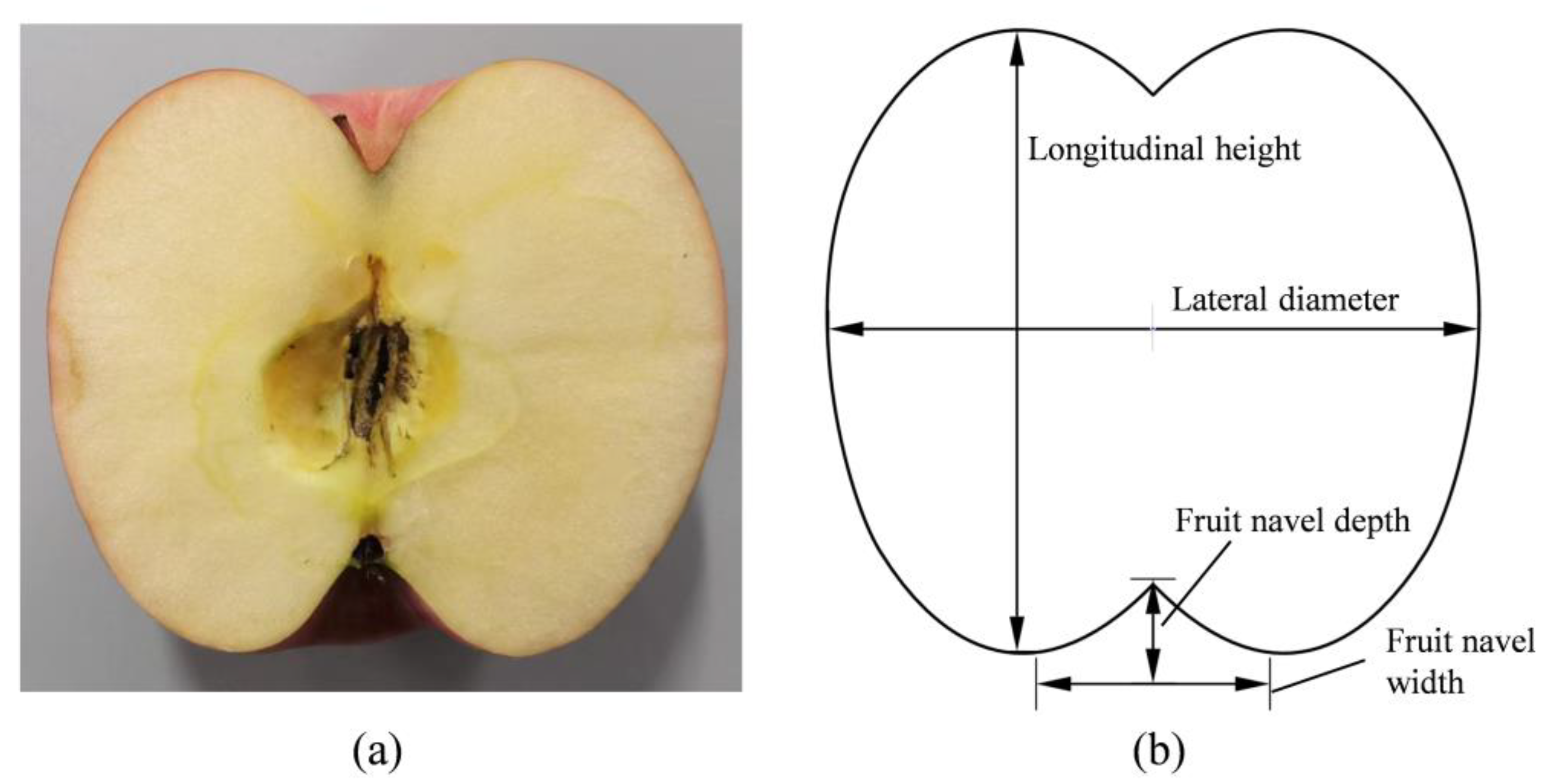
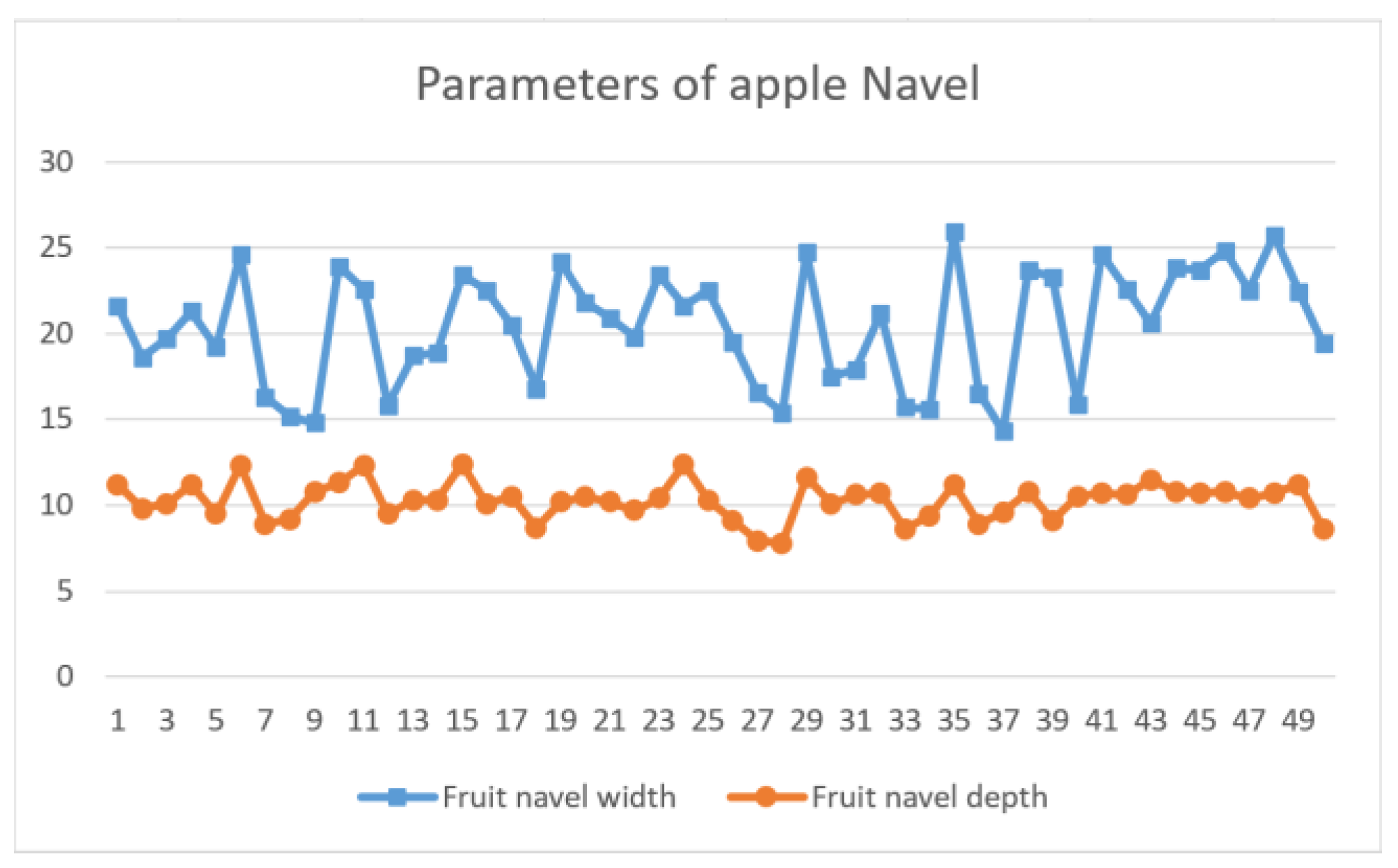
In order to determine the final area of the net opening, the type selection of the vacuum generator, and the shape of the adjustment ball in the posture adjustment slot, the shape characteristics of the apple need to be analyzed. The project group’s paper [31] has given fruit shape parameters for apple fruit weight (maximum 350 g), lateral diameter (average diameter of 80.2 mm, mainly in the range of 76–88 mm), and longitudinal height (average height of 76.4 mm), therefore, in this paper, only the width and depth of the apple fruit navel are measured, and apple fruit shape parameters are as shown in Figure 4. From the market, 50 red Fuji apples were randomly selected to measure the depth of the depression and the width of the opening at the navel end of the apple using Vernier calipers, the measurement results are shown in Figure 5. According to Figure 5, the depth of the fruit navel was between 9.6 and 10.8 mm and the width was between 17 and 24 mm.
3.2. Analysis of the Mechanical Properties of the Net Sleeve
The size of the opening of the net affects the wrapping property, protection, and aesthetics of the net cover for apples. As shown in Figure 6b, if the opening area of the net sleeve is too large, after the net sleeve is packed with apples, the net sleeve cannot shrink to the right position resulting in weak protection of the apples and poor aesthetics of the apples. For this purpose, the effect of the size of the opening of the net sleeve on its shrinkage characteristics has been experimented with. This experiment has the following four steps. In the first step, a roll of 20 m long and 7 cm wide non-cutting net sleeve was purchased randomly from the market, and several 14 cm long net sleeves were cut from this roll as the object to be tested. In the second step, since the average lateral diameter of an apple is 80.2 mm, we conduct a test experiment from the initial opening size of 80 mm. In the third step, a test experiment was conducted using the manner shown in Figure 6a, where the average lateral diameter apple was placed inside the net sleeve after the net sleeve was propped open, and the wrapping effect of the net sleeve was observed; In the fourth step, it was found that the net sleeve had the best wrapping effect on the apple when the opening size of the net sleeve was 130 mm as shown in Figure 6c, and the experimental results are shown in Table 2.
4. Apple Posture Adjustment Device Adjustment Principal Analysis and Design
4.1. Analysis of the Adjustment Principle of the Vertical Posture Adjustment Mechanism
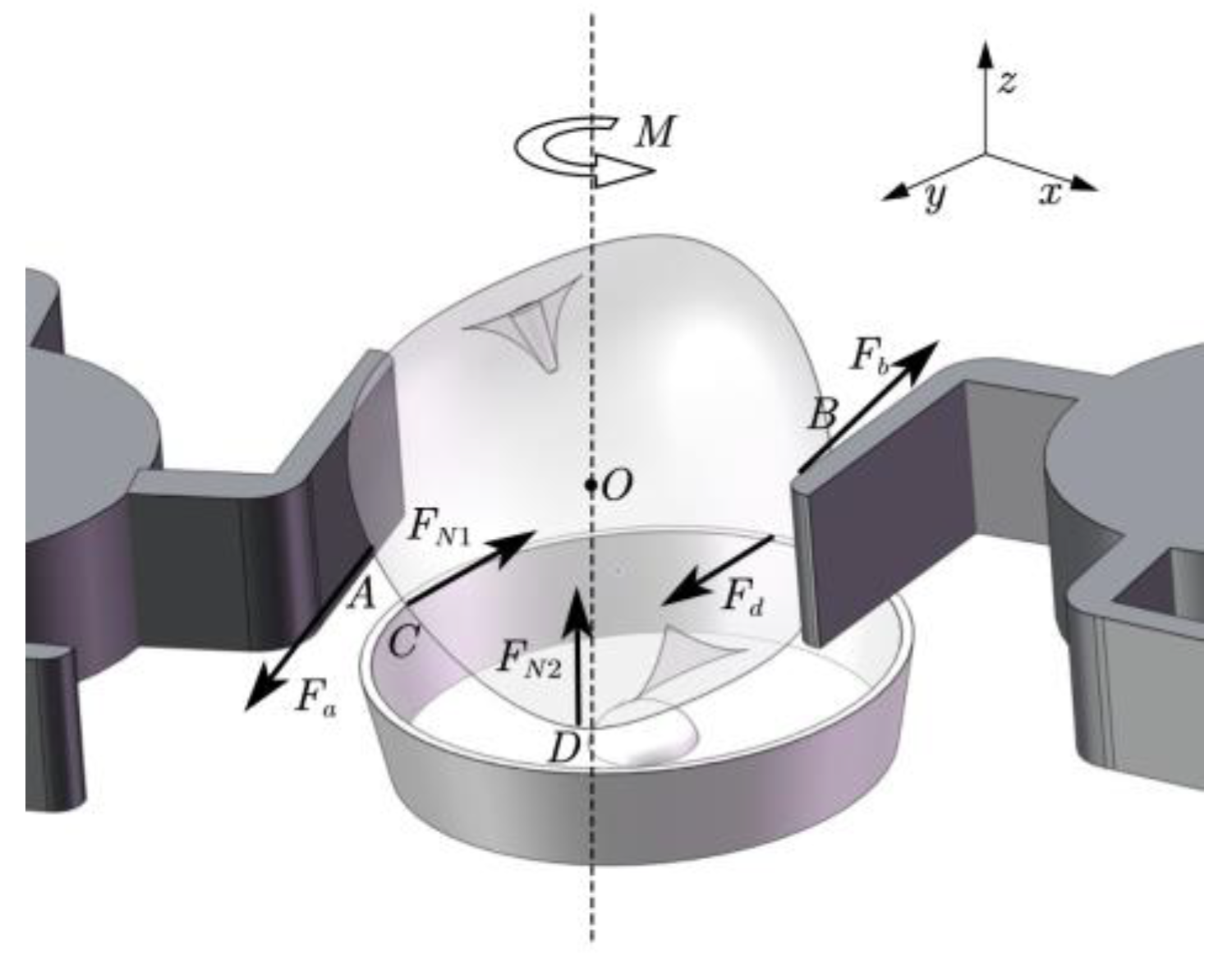
The apple starts to rotate and roll under the action of the posture adjustment disc, and the forces on the apple in the placement disc can be simplified, as shown in Figure 7. and are the friction forces of the posture adjustment disc on the apple; and are the support forces of the adjustment slot on the apple; O is the center of mass of the apple; M is the rotational force couple of the two posture adjustment discs on the apple; the points A and B are the contact points between the posture adjustment disc and the apple; the points C and D are the contact points between the adjustment slot and the apple. When the posture adjustment disc rotates under the drive of the sprocket, the apples are subjected to the frictional forces and of the posture adjustment discs on the apples, under the action of and , a rotational force couple M is generated at the apple center of mass O. Under the action of M, the apple rotates on the axis of the line where the center of mass O is located. During the rotation, the apple is in contact with the wall of the posture adjustment disc and a force F is given to the apple. The apple moves in the direction of F while rotating around the axis, when the concave part of the fruit navel is combined with the posture adjustment ball, the apple rotates on the axis of its own fruit axis without moving, and the posture adjustment of vertical placement is completed. The posture adjustment of the apple is performed entirely by the mechanical system, without the need to control the position of the apple with the visual system.
In order to illustrate that the apple rotates mainly around the Z-axis, the principle of D’Alembert’s principle is applied to analyze the principle of apple vertical adjustment. The equilibrium equation of the space force system is established:
Among them:
The solution gives:
where , , represents the inertial forces added to the Y, X, and Z axes of the apple; , , represents the moment of inertia added to the Y, X, and Z axes of the apple; , represents the support force of the apple posture adjustment slot on the apple; , represents the frictional force of the apple posture adjustment slot on the apple; represents the angle between and Z; represents the angle between and Z; m represents the mass of the apple; , , , and represent the distance from the contact point of C, D, A, and B to point O.
According to the actual design conditions, it is known that , so from the solved data, we know that . The apple rotates in the posture adjustment slot mainly around the Z-axis. When the recessed portion of the apple navel is combined with the stance adjustment ball, the vertical posture adjustment is completed.
4.2. Design of Vertical Posture Adjustment Mechanism
The specific structure of the vertical posture adjustment mechanism is shown in Figure 8, it consists of an apple posture adjustment disc, posture adjustment slot, chain plate, adjustment disc drive mechanism, and chain plate conveying mechanism. From the experimental analysis of apple shape characteristics, it was found that the lateral diameter of the apple was mostly in the range of 76–88 mm, the depth of the apple stalk was mostly 7–7.5 mm, and the width was mostly 20–25 mm. To ensure that the apples do not fall out of the posture adjustment disc during rotation, the height of the posture adjustment slot should be 1/3 to 1/2 of the lateral diameter of the apples, therefore, the height of the posture adjustment slot is designed as 38 mm, the height of the posture adjustment ball is designed as 10.2 mm, and the width is 20.4 mm. To reduce apple rotation damage, the wings and posture adjustment slots of the posture adjustment disc were 3D printed with flexible materials, and the apple posture adjustment slot and posture adjustment disk paste a layer of EPE pearl cotton used to protect the apple, which also increases the friction of the apple, reducing the speed of the apple rotation.
4.3. Design of Side Posture Adjustment Mechanism
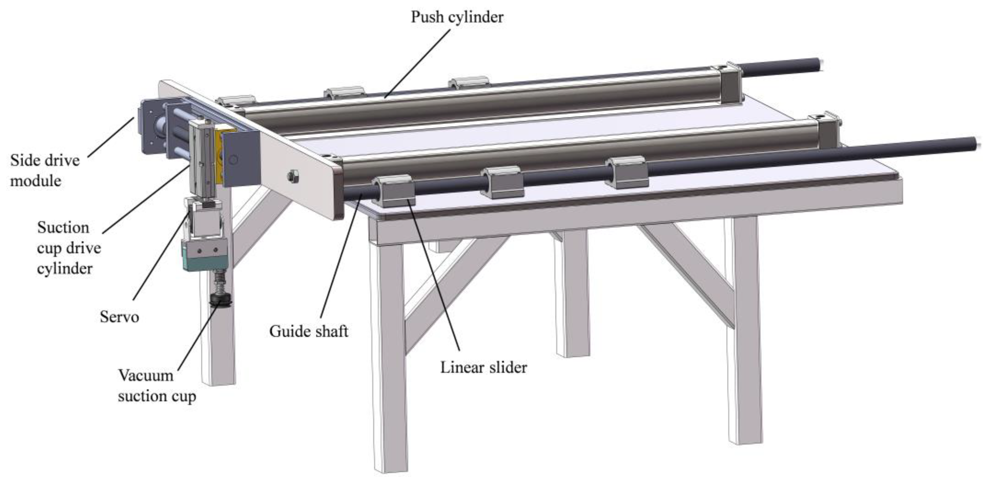
The role of the side posture adjustment mechanism is to adjust the side posture of the apples that have finished the vertical posture adjustment and to transport the apples that have finished the posture adjustment to the top of the net device. Its structure is shown in Figure 9, it consists of a push cylinder, guide shaft, linear slider, side drive module, suction cup drive cylinder, vacuum suction cup, etc.
The parameters of the vacuum generator need to be determined for the vacuum generator to have a suction force large enough to suck up the apples. The response time of the vacuum generator is 0.4 s in order to increase the packing speed. The maximum weight of the apple is 350 g.
The gravity of the apple as:
The vacuum level P of the required vacuum generator is as:
where represents the gravity of the load; t represents the safety factor; D represents suction cup diameter; n represents the number of suction cups.
The load gravity W is equal to the maximum weight of the apple . According to the working conditions, the pre-selection of a vacuum suction cup with a diameter of 40 mm and a safety factor of t = 8, then the data is substituted into Equation (5) to calculate the vacuum degree of 21.83 kPa.
Select the SMC ZH series vacuum generator, whose maximum vacuum level is , because = 0.2509, and the time required is = 0.32, which can be found in the vacuum generator manual. The average suction flow rate Q is:
The maximum suction flow rate Q is as follows:
where v represents the total adsorption volume; T represents the required vacuum response time; represents the resistance coefficient.
The total adsorption volume is 0.1 L. Due to the small flow resistance of the vacuum line, is taken as 2 and then the data is substituted into the Formula (7) to calculate .
According to , the manual shows that the vacuum generator ZH07BS with a nozzle diameter of 0.7 should be used, whose maximum inhalation flow is 12 L/min and average inhalation flow is 6 L/min. The actual suction response time is calculated by Equation (6) as 0.32 s, which is less than 0.4 s and meets the response requirement.
4.4. Finite Element Analysis of Guide Shaft of Side Posture Adjustment Mechanism
The guide shaft in the side posture adjustment mechanism is a cantilever beam when it is extended, and the force is mainly concentrated at the front end of the shaft. Finite element simulation analysis of the guide shaft is required to ensure that the guide shaft does not bend, deform, or break. Since the guide shaft needs to carry large forces, alloy steel with good hardness and toughness is chosen as the material whose physical properties are shown in Table 3. The total mass of the front part of the guide shaft, m = 3.3025 kg, was measured using an AnHeng ALH electronic scale (accuracy 0.01 g).
The total weight of the front-end parts of guide shaft G is as follows:
Because the side-release posture adjustment mechanism consists of two guide shafts and one cylinder shaft, the force F applied to a single guide shaft is expressed as follows:
where m represents the total mass of the front part of the guide shaft; g represents the acceleration of gravity, which in this case takes the value of 9.8 m/s2.
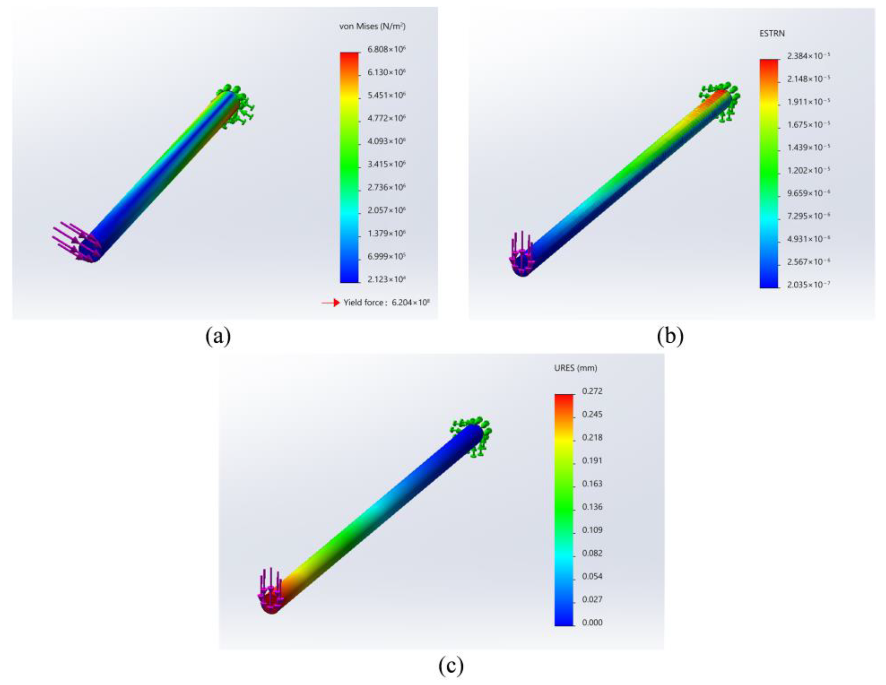
The force on the guide shaft calculated by substituting the data into Equation (9) is 10.7881 N. Finite element simulation of the guide shaft by SolidWorks, one end of the guide shaft is fixed, and the other end is loaded with a force of 10.7881 N. The simulation results obtained are shown in Figure 10.
According to Figure 10, it can be seen that:
where represents the maximum deformation stress of alloy steel material; stands for alloy steel material yield force.
The maximum strain of the guiding shaft is within the allowable strain range, and the maximum deformation stress is within the yield stress range, which can bear the gravity of the front part and complete the guiding work smoothly. It meets the requirements of use.
5. Design of Net Device
5.1. Design of Net Slack Mechanism
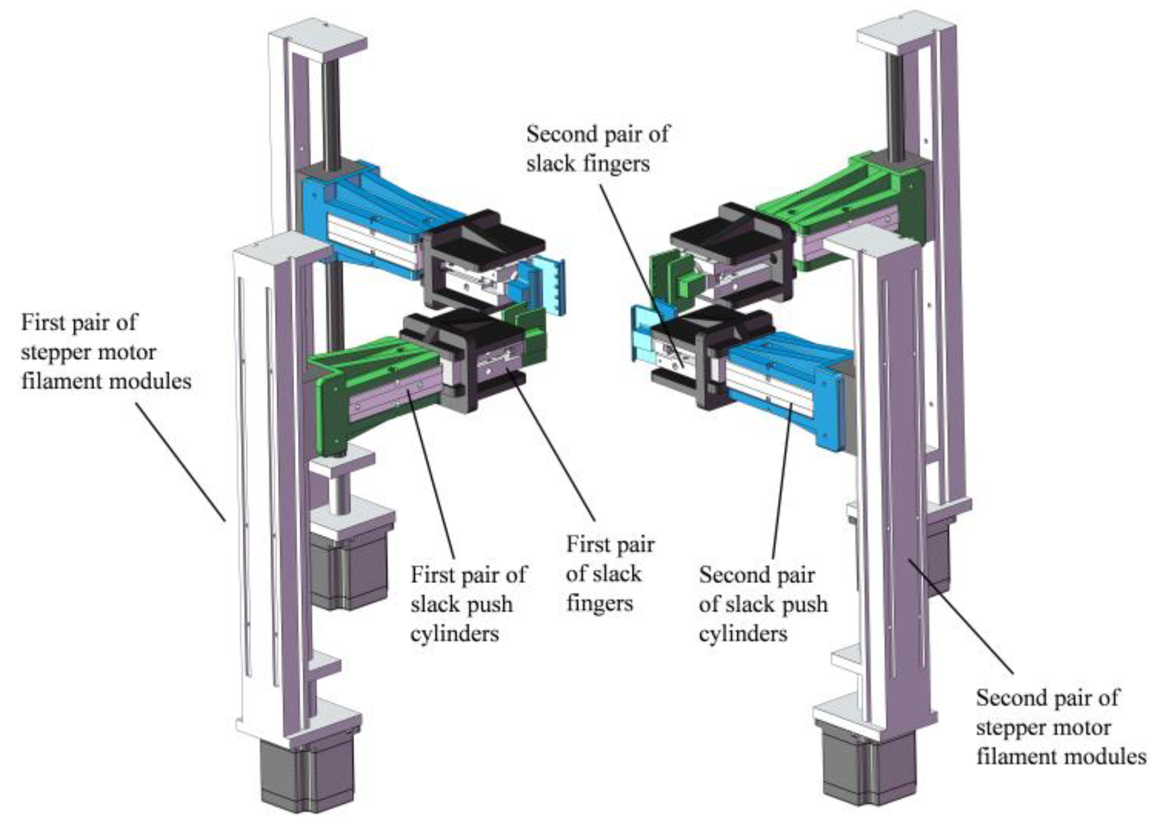
The purpose of the net slack mechanism is to open a small square opening in the original state of the web, providing the prerequisite for the final opening of the net, the specific structure is shown in Figure 11. The net slack mechanism mainly consists of the first pair of stepper motor filament modules, the second pair of stepper motor filament modules, the first pair of slack push cylinders, the second pair of slack push cylinders, the first pair of slack fingers and the second pair of slack fingers. As shown in Figure 12, the working process of the mesh sleeve relaxation mechanism has three steps as follows:
- (1)
- The first pair of net slackening push cylinders drive the first pair of net slackening fingers to move, when the front of the net slackening finger is 5 mm from the edge of the net, the net slackening finger is closed to clamp the net.
- (2)
- As shown in Figure 12a, the second pair of net slackening push cylinders push the second pair of net slackening fingers into motion, when the second pair of sleeve slack fingers moves to the end, the paired net slack fingers clamp the net by squeezing.
- (3)
- As shown in Figure 12b, the two pairs of mesh sleeve slackening push cylinders return simultaneously to slacken the mesh sleeve.
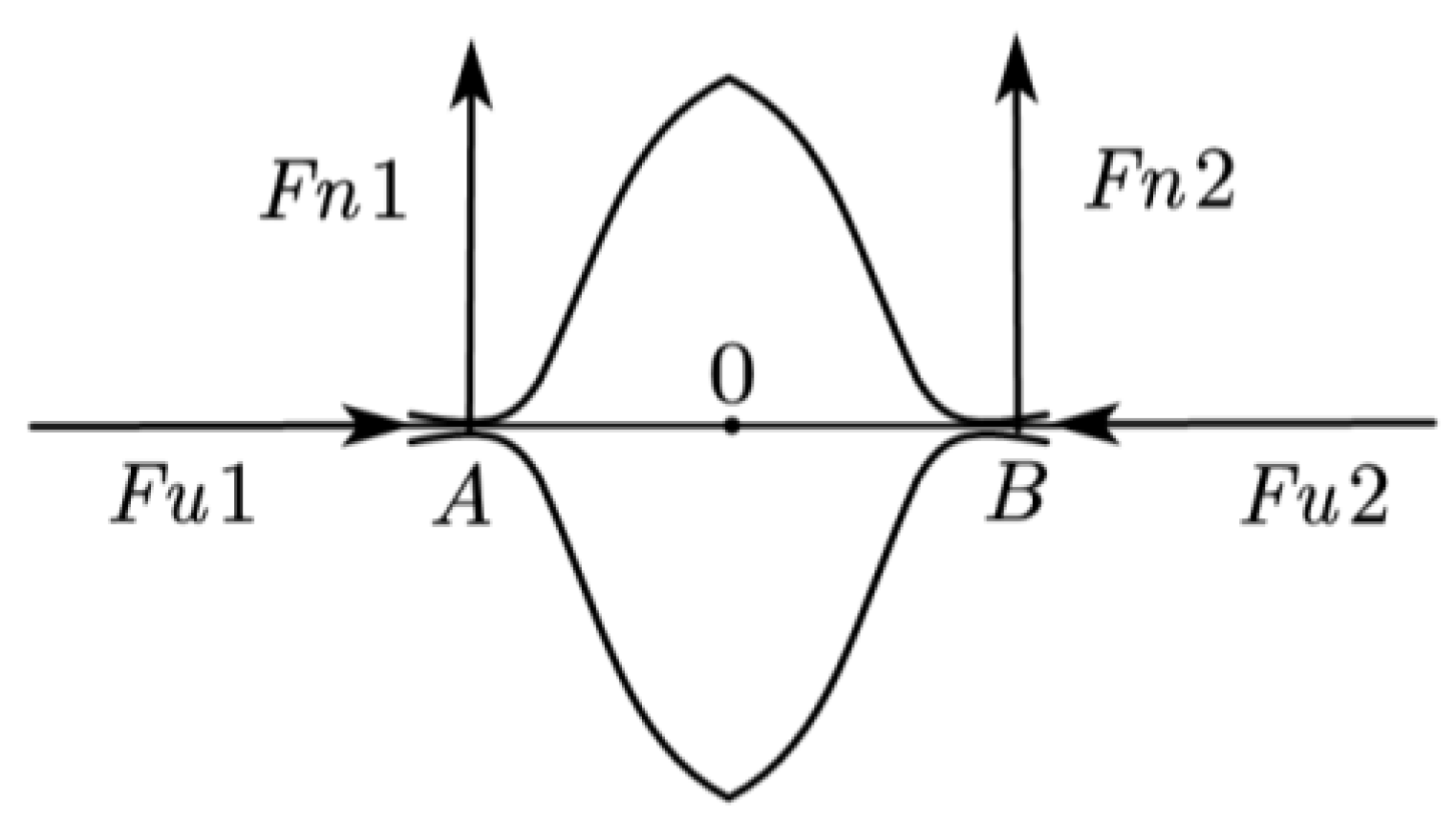
In order to illustrate the principle of squeezing and clamping the net sleeve, the side of the net sleeve that is squeezed by the second pair of slack fingers of the net sleeve is selected as the object of study for force analysis of the net sleeve. The mechanical diagram is shown in Figure 13, at points A and B, two slack fingers squeeze each other to apply two pressures and to the net. When the two fingers are closed, a pair of frictional forces and are applied to the net under the action of pressure. As the AB length of the net is squeezed tight by the slack finger when the finger is closed the AB section of the net sleeve will do contraction movement to the center 0 under the action of friction, and finally, the net sleeve is squeezed and clamped within the finger.
5.2. Design of Net Opening Mechanism
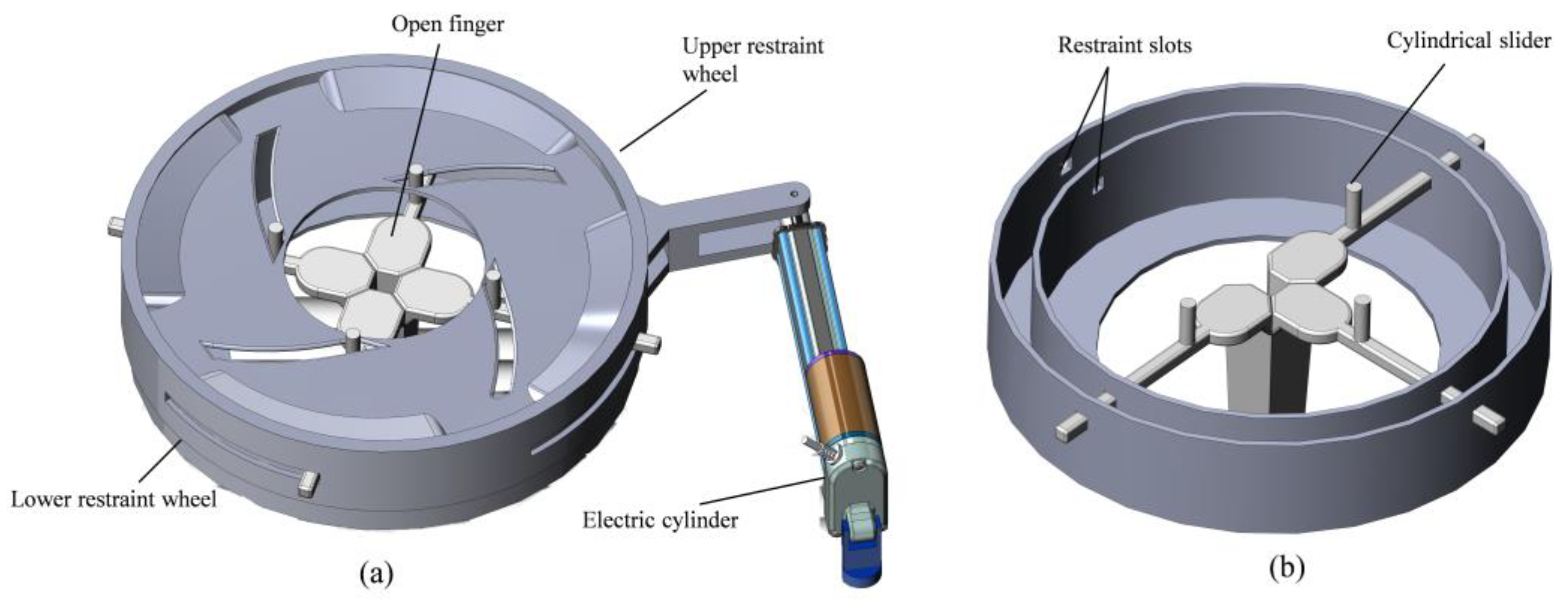
The role of the net opening mechanism is to finally open the net, and its specific structure is shown in Figure 14a. It consists of an Electric cylinder, upper restraint wheel, lower restraint wheel, and open finger. Through the expansion and contraction of the electric actuator to achieve the opening and closing of the opening finger to open the purpose of the net sleeve located below the opening finger, the shape of the net sleeve is a rectangle after opening. As shown in Figure 14b in order to limit the movement of the mechanical fingers so that they can only move in the radial direction of the opening mechanism, the lower restraint wheel uses four restraint slots to limit the direction of finger movement. After fixing the lower restraint device, the upper restraint device can be rotated clockwise and counterclockwise under the action of the electric cylinder. For the upper restraint device to drive the four spreader fingers to open and close, the slide curve of the upper restraint device needs to be parameterized.
As the cylindrical slider moves away from or near the center of the restraining wheel, it is the groove edge of the upper restraining wheel that provides power to the slider. As shown in Figure 15a, the force analysis of the propped finger is carried out with the position of the circle center of the cylindrical slider as the coordinate origin.
Within the figure, represents the combined force of the slide on the finger; represents the component force of in the direction of finger movement; stands for frictional resistance; represents the angle between the combined force and the direction of motion.
The side walls of the slots and the sides of the cylindrical sliders belonging to the opening fingers are in contact with each other to prevent relative sliding. As shown in Figure 15b, due to the self-locking phenomenon, if the line of action of the combined force of all the main forces acting on the opening finger is within the friction angle and is directed toward the support surface, no matter how strong the force is, the opening finger must remain stationary. If the line of action of the combined force of all the main forces is outside the friction angle, no matter how small this corner is, the opening finger must slide. The friction angle was calculated as follows:
where represents the maximum frictional resistance; stands for coefficient of sliding friction.
Therefore, it is only necessary to ensure the mechanical fingers slide smoothly along the slots by ensuring that . Based on the self-locking principle, this paper provides the following two design solutions for the slide curve. The first one is the equiangular spiral line type chute curve; the second one is the circumferential type chute curve. The first of these is given only for theoretical verification, and the second scheme is used for actual manufacturing.
5.2.1. Design of Equiangular Spiral Type Chute Curve
Suppose there is a chute trajectory curve as shown in Figure 16a, in which O point is the center position of the opening mechanism, and the angle a remains constant during the movement of the open finger, then two straight lines tangent to the slot curve can be obtained through points A and , and the angle between these two lines and OA and OB will always beα. Specify that represents a line tangent to the chute curve; represents the slope of the line segment formed by the point O joining the tangent point. A further simplified model is shown in Figure 16b.
According to the external angle property of the triangle and the formula of two angles and tangent, Equation (12) can be obtained.
Establish the polar equation:
Substituting and into to organize them gives:
It can also be written as .
Simplify to obtain:
From the above calculation, the equation of the curve can be obtained as:
This curve is an equiangular spiral, and the curve parameters can be determined according to the actual working conditions during the application. It is only necessary to ensure that , this curve can make the radial motion of the propped finger in the slot.
5.2.2. Design of Circumferential Type Chute Curve
As shown in Figure 17a, suppose the trajectory curve to be sought is part of a circle, the trajectory circle intersects the outer circle with point B, point B is always on the Y-axis, and the center A of the trajectory circle is always on the X-axis.
In order to minimize frictional resistance, the upper constraining circle and the opening finger are made using smooth photosensitive resin material using 3D printing technology. The friction coefficient of photosensitive resin material is equal to 0.21 [32]. The magnitude of the friction angle is calculated by Equation (10) as 11.86°.
When the upper constrained circle is rotated from point C to point B, Equation (18) is obtained from the sine theorem.
During the movement of the upper constrained circle from point C to point B, gradually increases, and since is a constant value, the value on the right side of equation (18) decreases. Since the value of AO remains unchanged, the value of gradually increases, and has a maximum value when the upper constraint circle moves to point B. Based on the above analysis, just make sure that at point B, that is, when AD is less than , the finger can move in the chute.
Based on the test experiment of the effect of the size of the opening of the foam mesh sleeve on its shrinkage characteristics, in order to make the mesh sleeve can achieve the best effect of wrapping the apples. The distance between the two mechanical fingers facing each other when the mechanical fingers are open is designed to be 130 mm. Since the gap between the two mechanical fingers facing each other when the mechanical fingers are closed is 16 mm, the distance for the mechanical fingers to move is as follows: . The diameter of the smaller concentric circle is specified as 150 mm according to the actual demand, and the values of the diameters of the larger concentric circles are as follows: . After determining the size of the two concentric circles and the size of circle A, is the required track.
Specify , and according to the sine theorem, the value of AB is calculated as follows:
Substituting BO = 132 into Equation (19), the radius of circle A is calculated to be 186.68. The coordinate of A is (0.132).
The equation of circle A is as follows:
The equation of the smaller concentric circle and circle A are combined to obtain the following equation:
Solving the system of Equation (19) yields the following calculation:
Substitute x = −44.69, y = 60.23 into Equation (20) to calculate = 36.58°, the angle occupied by is 36.58°. Therefore, the upper restraint wheel only needs to turn 36.58° to complete the opening and closing action of the mechanical finger. The circumferential chute curve after the design parameters are determined is shown in Figure 17b.
5.2.3. ADAMS Simulation Analysis of the Circumferential Opening Mechanism
Dynamic analysis was performed using the ADAMS View software to verify the rationality of the chute curve design of the circumferential opening mechanism. Build a model of the opening mechanism in SolidWorks according to the circumferential chute curve. As shown in Figure 18, the model was imported into the ADAMS View software, and a coordinate system centered on the circular position of the opening mechanism was established. The simulation results are shown in Figure 18. First, the material parameters of the parts are edited, the upper constraint wheel is set as a rotating sub-connection and the lower constraint wheel as a fixed one, then the binding force is added to each part in turn, and finally, the simulation analysis is performed.
According to Figure 19a, the initial positions of the upper and lower opening fingers on the Z-axis are −43.125 and 43.125, respectively, and the end positions are −100.1702 and 100.1702, respectively. The distance traveled in the Z direction by both braced fingers is = 100.1702 − 43.124 = 57.0452 mm, within the allowable error range of the theoretical design parameter of 57 mm. According to Figure 19b, the initial coordinates of the upper constrained wheel center of mass are A (16.5638, −9.5717), the coordinates of the end position are B (7.5643, −17.5095), and the rotation angle is as follows: , within the allowable error range of the theoretical design parameter of 36.58°mm.
The above analysis results show that the theoretical design and simulation verification results of the chute curve of the circumferential opening mechanism are the same within the tolerance range. The circumferential opening mechanism made in this paper can brace the mesh sleeve while ensuring the best wrapping effect of the net sleeve.
5.3. Design of Net Traction Conveying Mechanism
The role of the net traction conveyor is to convey the net sleeve and pull the fused net sleeve back to the initial position. The specific structure is shown in Figure 20, which consists of a traction drive ball screw, traction finger, traction roller, guide roller, and net sleeve storage tray. To prevent the net sleeve from swinging during lifting or pulling down, cylindrical projections and grooves are designed to match each other on the cylindrical surface of the traction rollers. Based on this design, the net sleeve can be confined inside so that the net sleeve can only move in the direction of lifting or pulling down to prevent the net sleeve from swinging from side to side.
6. Design of Control System
6.1. The Overall Design Idea of the Control System
This machine adopts an STM32F1 series microcontroller as the core chip of the apple foam net sleeve packaging machine control system. Control system hardware includes: Servo for controlling the rotation of the vacuum suction cup (Model: TD-8120MG, blocking torque 20 kg/cm3); Dual optical axis ball screw stepper motor module to control apple side release adjustment and traction finger up/down movement (Model: GGP8080, effective stroke 200 mm); 57 stepper geared motor controlling the rotation of the apple posture adjustment disc (Model: 23HDB76-30PG, torque 2.3 Nm); Single line rail ball screw module for controlling up and down movement of slack fingers (Model: SGX, effective stroke 250 mm); Electric cylinder to control the opening and closing of the opening mechanism (Speed 100 mm/s, effective stroke 150 mm); DC geared motor for controlling the discharge conveyor (Model: 5D120-GU-2, power 120 W); Solenoid valves for controlling each pneumatic actuator(Model: two-position five-way 4V210-08); Relay to control solenoid valve on/off (Model: JQC-3FF-S-Z); DC24V switching power supply; Infrared pair of tube sensors (Model: Opposing photoelectric switch NPN type, opposing distance: 1000 mm); Stepper motor driver (Model: PFDE-DM542, built-in three generations of 32-bit DSP processor).
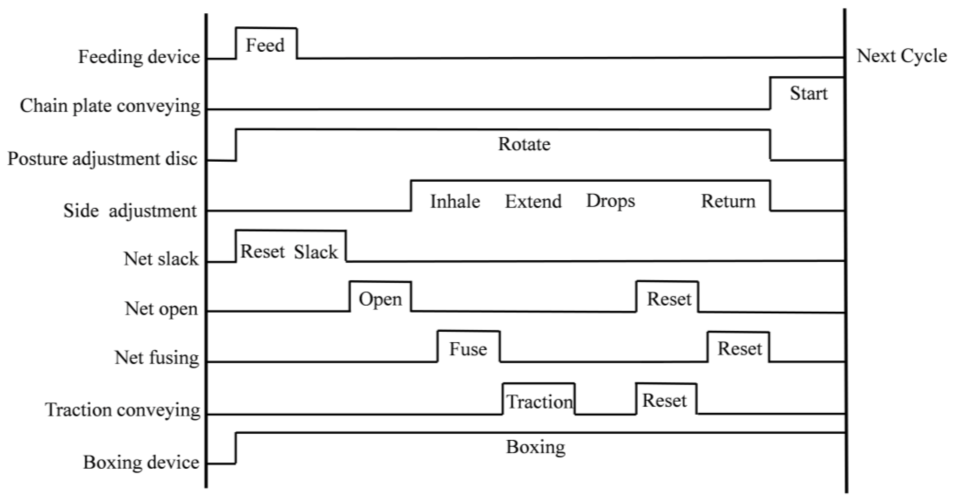
This machine uses a combination of electric and pneumatic components to actuate, with a combination of interrupt and timer control to link each control hardware of the packaging machine. Control the work of each electric element and pneumatic element with the feedback signal from the infrared pair of tube sensors as a sign. Precise control of stepper motor ball screw module slider position, stepper motor speed, servo rotation angle, relay and solenoid valve on and off, pneumatic finger opening and closing, cylinder extension and return. Whether the apples need to be conveyed in the packaging machine, whether the apple posture adjustment plate needs to adjust the posture of the apples, when the propping mechanism opens, and when the traction conveying mechanism pulls the net sleeve, all need to be judged according to the position of the apples. The machine uses an infrared tube sensor to detect the position of the apple and feedback to the microcontroller to control each mechanism to execute the corresponding action. The control timing of the machine is shown in Figure 21.
6.2. Design of Motor Drive System
The packaging machine uses the STM32F103VET6 main control chip with stepper motor driver output PWM pulse width adjustable square wave signal to accurately control the speed of the stepper motor. The stepper motor driver has three signal terminals: pulse signal (PUL), direction signal (DIR), and enable signal (ENA), respectively. The driver and the controller have two wiring methods: a common cathode connection and a common anode connection, the common anode connection is used in this paper. Since the model 57 stepper motor is used, the power supply voltage of the stepper motor driver is DC24V. The relationship between timer frequency and speed needs to be determined for accurate control of stepper motor speed, the speed n of the stepper motor can be obtained from Equation (21).
where S represents the step angle of the stepper motor; X represents the subdivision value of the drive; TIM3_ARR represents the value of the Auto Reload register; TIM3_PSC represents the value of the Prescaler.
The machine uses a stepper motor with a steep angle of S = 1.8° and a drive subdivision value of X = 16, requiring a speed of n = 12.5 r/s, substitute the above data into Equation (21) to obtain TIM3_ARR = 299 and TIM3_PSC = 599.
The control of the servo uses the PWM1 output comparison. In order to make the microcontroller feedback a signal that can make the servo rotate 90°, it is necessary to calculate the relationship between the servo rotation angle and the pulse width (duty cycle). The machine uses a 180° servo and uses a pulse width of 20 ms to modulate PWM, with a pulse width of 0.5–2.5 ms partly used to control the servo angle. The angle duty cycle of the servo is between 0.025 and 0.125, and the servo rotation angle is 90° when the pulse width is 1.5 ms. Set the value of Auto Reload Register (TIM4_ARR) to 999 and the value of Prescaler (TIM4_PSC) to 1439. The value of duty cycle P can be calculated from Equation (22).
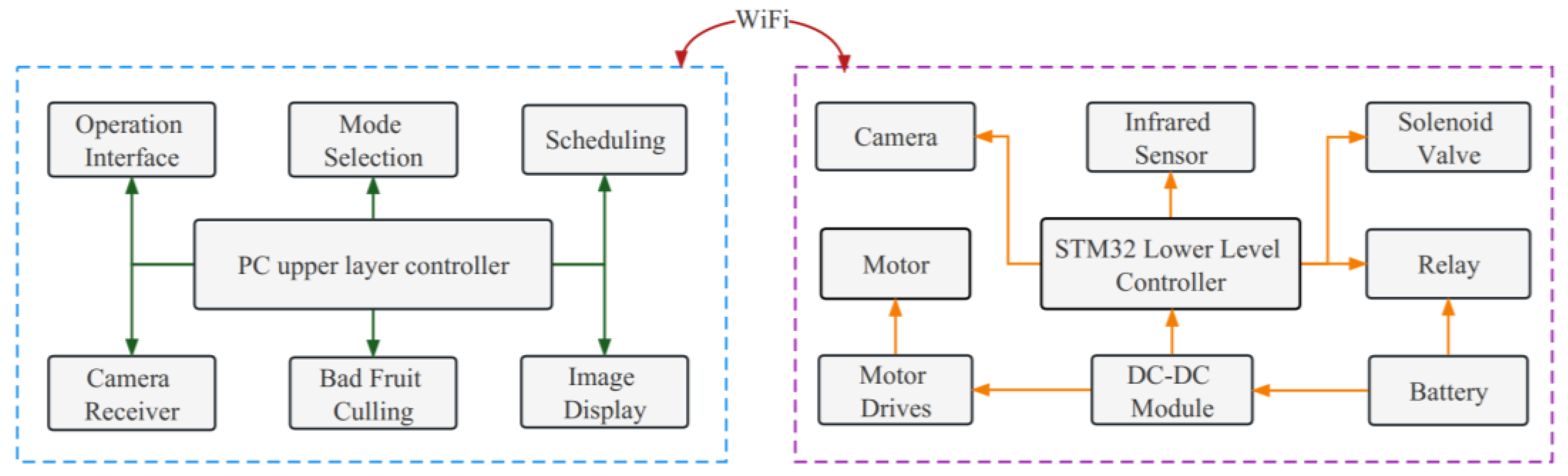
The initial CRR value is 25, and the duty cycle P is 0.025 by substituting the ARR of 999 into Equation (22), indicating that the servo rotation angle is zero currently. When an angle is 90° use Equation (23) to calculate Out_angle is 75, that is, the value loaded to the comparison register CRR is 75. Substituting the value of CRR into Equation (22), the calculated P is 0.075, indicating that the rudder rotation angle is 90° currently. Using the above design, it is possible to achieve boundary processing for duty cycles that exceed the range, accurately output the required pulse width, and precisely control the servo rotation angle. The machine control architecture is shown in Figure 22.
7. Packaging Machine Prototype Experiment
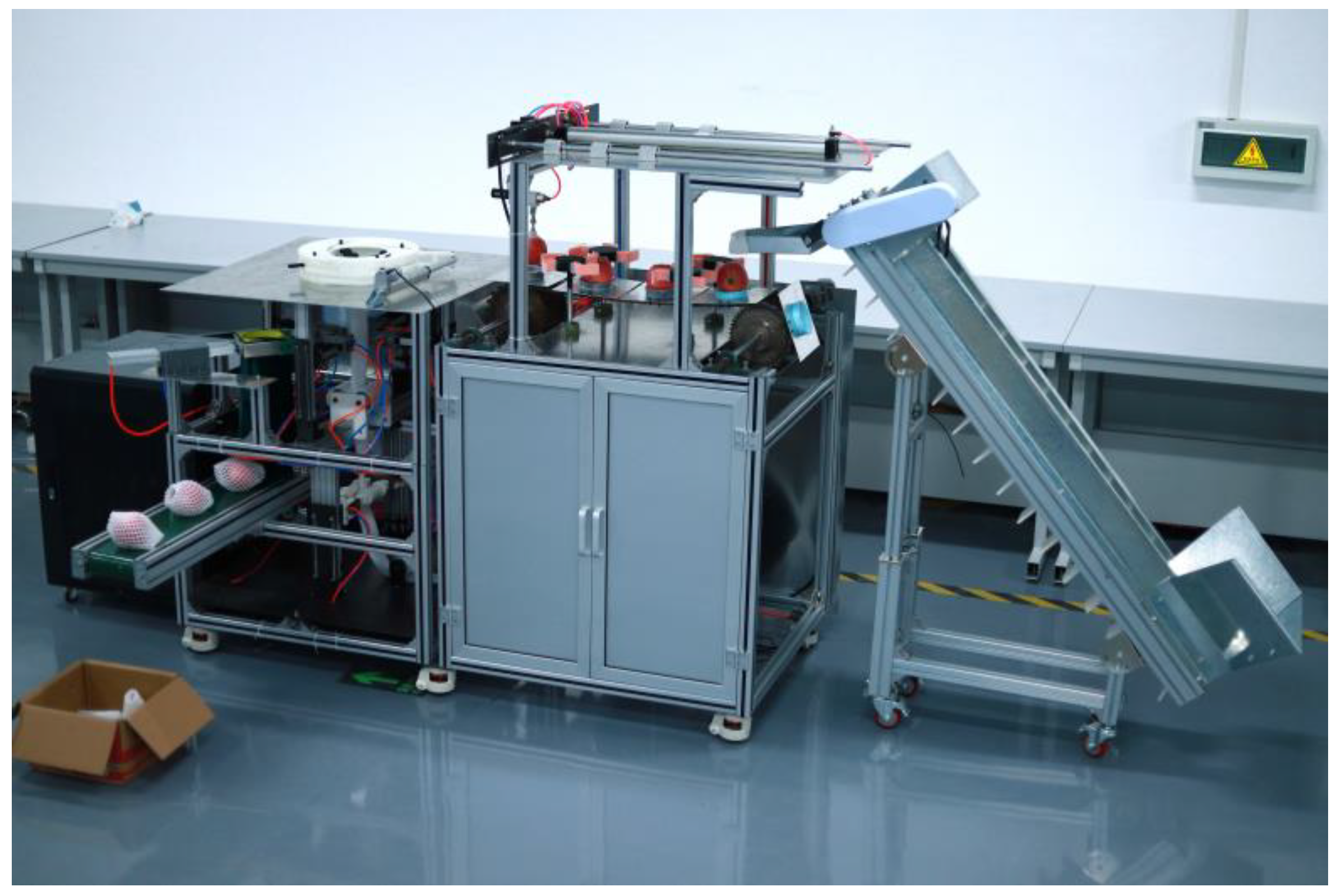
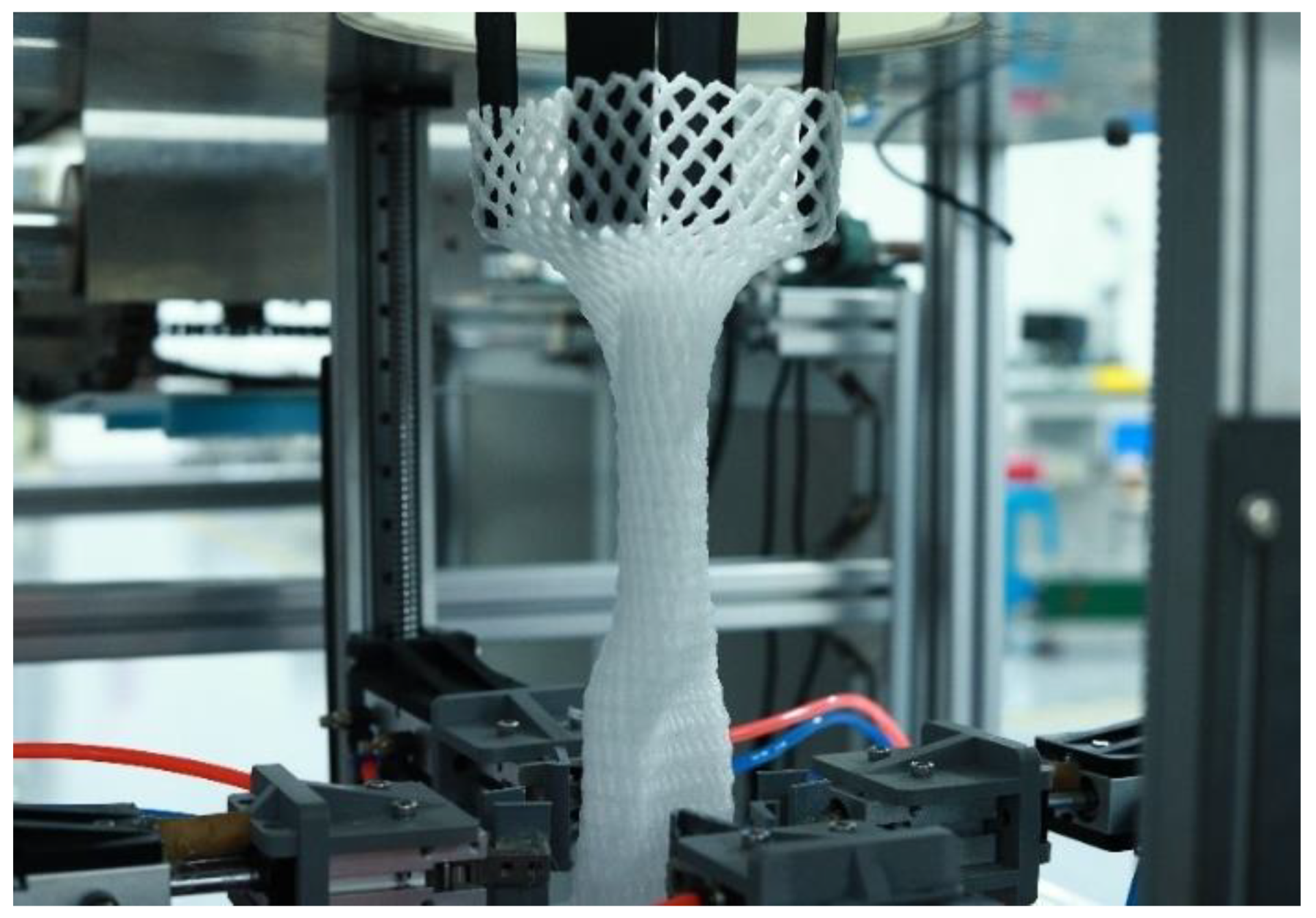
As shown in Figure 23, according to the above mechanism design ideas and principles using SolidWorks to complete the virtual prototype construction work and processed the prototype of the apple foam mesh sleeve packaging machine. In order to test the apple posture adjustment rate and netting success rate of the prototype, 100 red Fuji apples were selected from the market for the prototype experiment. The average lateral diameter of the sample apples was 80 mm, and the average longitudinal height was 70 mm. Since this machine has both an apple posture adjustment function and a net packing function, the product of the posture adjustment success rate and the net success rate is used as the packing success rate of this machine. The working screen of the nesting device is shown in Figure 24. The experimental results are shown in Table 4.
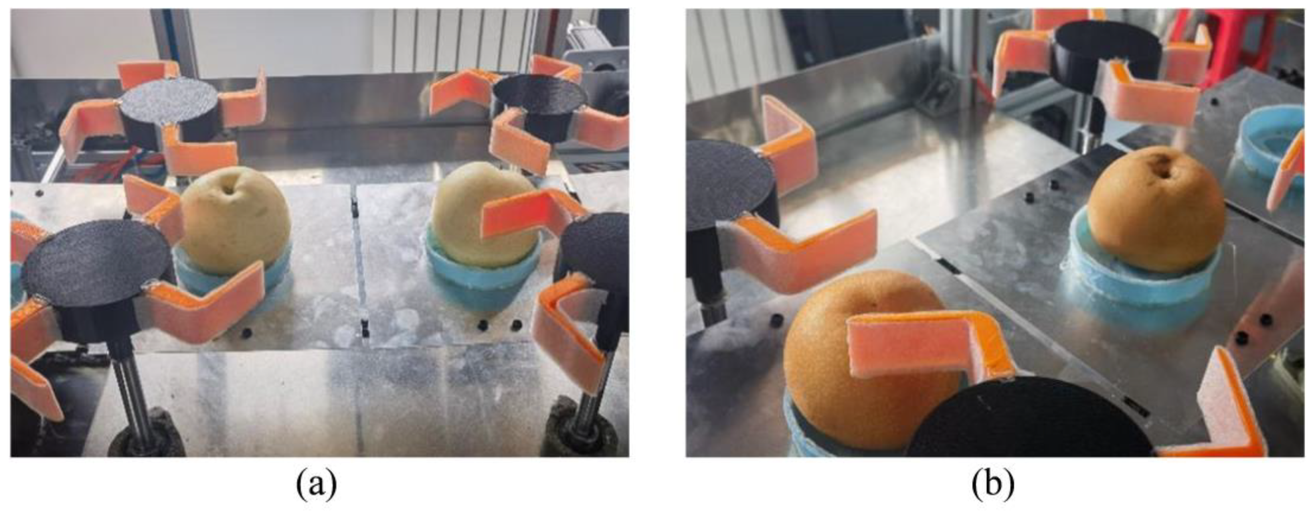
The experimental results show that the apple foam net sleeve packaging robot can complete the basic functions of apple feeding, posture adjustment, net sleeve conveying and traction, net sleeve slackening, net opening, and so on. As can be seen from Table 4, the packing rate is 98.10%, the cut mesh sleeve is mainly within 138–143 mm, the single fruit packing speed is 10 s/each, and the working efficiency is 355–365 pcs/h. The packaging machine-working objects are not only limited to apples. As shown in Figure 25, the posture adjustment device can be used for fruits with similar shape characteristics to apples and with depressions at the navel and stalk ends, such as crown pears and autumn moon pears, the netting device can be used for fruits with a diameter of less than 130 mm, such as oranges, pears, oranges, kiwis and other spherical fruits.
8. Discussion
In this study, we propose a secondary posture adjustment method based on the analysis of the shape characteristics of apples with a vertical posture adjustment mechanism and a side posture adjustment mechanism. Based on the observation of human hand-set nets and the analysis of the mechanical characteristics of nets, a dual-system net opening method combining a net slackening system and a net opening system was proposed for fruit top-down mesh sleeve bottom-up. The research in this study is as follows:
- (1)
- Experimental basis: Experiments on the analysis of apple shape characteristic parameters and the effect of foam mesh sleeve opening size on its shrinkage characteristics were conducted to provide an experimental basis for the selection of packaging machine design parameters.
- (2)
- Principal analysis: Analysis of the principle of vertical release attitude adjustment based on D’Alembert’s principle and analysis of the principle of the chute curve of the opening mechanism based on the self-locking principle.
- (3)
- Design simulation: SolidWorks-based 3D virtual prototype construction, mechanical analysis of the apple foam sleeve wrapping machine, and ADAMS View-based dynamics analysis of the sleeve opening mechanism chute curve.
- (4)
- Prototype experiments: From Table 4 in Section 7, it can be seen that the packing rate is 98.10%, the single-fruit packing speed is 10 s/pcs, and the working efficiency is 355–365 pcs/h. The operation of the packaging machine is not only limited to apples but also to pears, peaches, oranges, and other spherical fruits.
8.1. The Advantages of This Study
At present, the apple foam net sleeve packaging machine net sleeve method mostly uses the fruit from the bottom-up net sleeve from the top-down cylindrical sleeve with mechanical clamping jaws of the multi-actuator net sleeve method and does not have the apple posture adjustment function. Xu et al. developed a packaging machine with a single fruit packing speed of 25 s/pcs, and Hu et al. developed a packaging machine with a single fruit packing speed of 4.6 s/pcs [25,26,27,28]. This nesting method is effective for low-speed nesting packages and when the foam nesting material is suitable. However, the clamping force of the mechanical jaws, frictional force on the outer surface of the cylindrical sleeve, and complex links of this method are ignored. For example, improper control of the clamping force of the mechanical gripping jaws causes the net sleeve to be easily pulled off when sliding on the cylindrical sleeve; excessive friction on the outer surface of the cylindrical sleeve causes the net sleeve to slide on the outer surface of the cylindrical sleeve at a slower rate or fail to slide; this method requires a specific sleeve link to wrap the open net sleeve over the apple after opening the net sleeve. These factors can reduce the utilization of the net sleeve and the packaging efficiency. Moreover, most of the existing apple foam net sleeve packaging machines do not have an apple posture adjustment function and cannot meet the market demand for apples to achieve two types of net sleeve packaging, namely, vertical net sleeve packaging and side net sleeve packaging, which makes it difficult for traditional packaging machines to adapt to the changes in the apple packaging market.
The advantages of this study are as follows: First, based on the observation of human manual set nets and net sleeve opening size on the shrinkage characteristics of the experiment, a fruit top-down net sleeve bottom-up net slackening system and a net opening system combined with a dual-system net opening method to improve the net sleeve packaging efficiency and reduce the rate of net sleeve damage. In this method, the impact force generated by the potential energy of the apples when they fall is cleverly used to allow the apples to be covered by foam netting in the process of falling, reducing the need for specific sleeve links; the opening mechanism designed by this research only uses one electric actuator to open the net sleeve, which reduces the manufacturing cost and improves the packaging efficiency compared with the traditional multiple cylinders moving simultaneously to open the net sleeve; compared with the traditional mechanical jaws and cylindrical sleeve opening method, this method eliminates the traditional cylindrical sleeve and mechanical jaws, and adopts a new net sleeve opening method with a slackening mechanism and an opening mechanism, which reduces the damage rate of the net sleeve. As shown in Table 5 the packing time of a single fruit is 4 s/pcs when the net device works alone, which significantly improves the packing speed compared to the conventional 25 s/pcs and 4.6 s/pcs. Second, based on the analysis of the shape characteristics of apples, a secondary posture adjustment method was proposed to realize two different net sleeve packaging methods for apples, namely, vertical net sleeve packaging and side net sleeve packaging, by combining a vertical posture adjustment mechanism and a side posture adjustment mechanism. As shown in Table 6 when the posture adjustment device works alone, the adjustment time for a single fruit is 9.5 s/pcs.
8.2. Application Prospects and Economic Benefits
At present, with the improvement of living standards, fresh fruit consumption has become the mainstream form of fruit consumption. With the development of the e-commerce and logistics industry, to reduce fruit damage during transportation, the demand for apple net sleeve packaging is increasing, but the cost of high-efficiency low manual packaging is difficult to adapt to the current environment. This study designs and builds an apple foam net sleeve packaging machine with a posture adjustment function applied to the apple packaging field, which can improve the efficiency of apple foam net sleeve packaging, free hands to reduce manual work intensity and meet the market demand for diversified apple net sleeve packaging. The net and attitude adjustment devices of this packaging machine can be used as separate parts, which makes it easy to realize docking with the apple packaging line and has great prospects for future applications.
This study solves the existing net sleeve packaging machine in net sleeve packaging with low packaging efficiency, net sleeve damage, packaging function single problem, traditional manual work labor intensity, and low-efficiency problems. The processing and manufacturing costs of the existing apple net sleeve packaging machine are high (up to 100,000 yuan per unit), but the apple foam net sleeve packaging machine built in this study uses electricity as the main energy source of approximately 2.1 kw·h, and the processing cost is low (40,000 yuan per unit). The apple packaging method provided in this study makes apple packaging more intelligent and efficient, in line with the needs of modern society, and has good economic benefits.
9. Conclusions
- (1)
- Traditional manual packaging methods have the following problems: manual packaging labor is costly, inefficient, and cannot be operated continuously with limited daily working hours. The existing apple net packaging machine has the following problems: High processing and manufacturing costs (up to 100,000 yuan per unit); Large size is not adapted to the national conditions of Chinese apple retail farming; The single form of packaging cannot meet the market demand for packaging diversification; The form of net support mostly adopts the form of a sleeve with a manipulator which is easy to pull off the net sleeve causing a low utilization rate of the net sleeve. The apple foam mesh sleeve packaging machine designed in this paper has the following advantages: The machine is small in size, can operate continuously, and has a low processing cost (40,000 yuan per unit); Two different types of packaging can be realized for apples: vertical packaging and side packaging, so the machine packaging form diversification to meet the market demand; using the combination of the net slackening mechanism and the net opening mechanism to improve the utilization rate of the net sleeve. Therefore, the packaging machine designed in this paper can be a good solution to the above problems.
- (2)
- In this paper, experiments were conducted on the effect of the opening size of the net sleeve on its shrinkage characteristics. The experimental results showed that the best wrapping effect on apples was achieved when the net opening size was 130 mm. The design and analysis of the adjustment principle of the vertical posture adjustment mechanism, the selection of the vacuum generator of the side posture adjustment mechanism, the squeezing and clamping principle of the net slackening mechanism, and the chute curve of the net opening mechanism of the apple foam net packaging robot were carried out. The analysis results showed that the upper constraint wheel slideway curve can be equiangular helix type or circumferential type, this paper adopts circumferential type for physical design. The calculation results showed that the finger can be moved in the slide groove when the control ∠AOB was less than 78.14°. According to the actual working condition, ∠AOB = 45° was selected and the rotation angle of the upper constraint wheel was calculated to be 36.58°.
- (3)
- SolidWorks software for static analysis of the guiding axis of the apple side release posture adjustment mechanism. According to the simulation results, we can see that , , . The maximum strain of the guiding shaft was 2.384 within the allowable strain range, and the maximum deformation stress was within the yield stress range, which can withstand the gravity of the front part and complete the guiding work smoothly to meet the requirements of use. ADAMS View software was used to analyze the dynamics of the circumferential bracing mechanism to verify the rationality of the slide curve design. According to the simulation results, it can be seen that the travel distance of the opening finger in the Z direction is 57.0452 mm, which is within the error tolerance of the theoretical design parameter of 57 mm, the rotation angle = 36.61° is within the error tolerance of 36.58° of the theoretical design.
- (4)
- Based on the 3D model and the results of theoretical analysis, a physical prototype of the apple foam net packaging machine was built, and apple packaging experiments were conducted. Prototype experimental results showed that the machine can realize the continuous operation of feeding, posture adjustment, and nesting and boxing of red Fuji apples. The success rate of machine posture adjustment was 99%, the success rate of the net sleeve was 99%, the packing rate was 98.10%, the fused net sleeve was mainly within 138–143 mm, the packing speed of single fruit was 10 s/pcs, the working efficiency was 355–365 pcs/h and the working object was not only limited to apple, but also to pear, peach, orange, and other spherical fruits.
In the future, the project team will further optimize the structure of the posture adjustment device to improve the machine’s inclusiveness for different varieties of apples; analyze the damage mechanism of apples to reduce the damage problem of apples in the packaging process; and conduct kinematic analysis on the principle of apple posture adjustment to further understand the adjustment principle. In addition, the structure and software system will be further optimized to expand the machine into net sleeve packaging for more fruit varieties.
Author Contributions
Conceptualization, S.H. and Q.S.; methodology, S.H.; investigation, Q.W. and Z.L.; writing—original draft preparation, S.H.; writing—review and editing, S.H., Q.S. and Y.Z.; software, S.H., Q.W. and Z.L.; validation, S.H., Q.S. and X.Y.; formal analysis, S.H. and H.X.; project administration, S.H., Q.S. and Y.Z.; supervision, S.H. and Q.S.; funding acquisition, S.H. and Q.S. All authors have read and agreed to the published version of the manuscript.
Funding
This research was funded by Discipline with Strong Characteristics of Liaocheng University—Intelligent Science and Technology under Grant 319462208, and Liaocheng University Undergraduate Innovation and Entrepreneurship Training Program under Grant CXCY2022368.
Data Availability Statement
Not applicable.
Conflicts of Interest
The authors declare no conflict of interest.
References
- Huo, X.; Liu, T.; Liu, J.; Wei, Y.; Yao, X.; Ma, X.; Lu, P. China Apple Industry Development Report in 2020. China Fruit Veg. 2022, 42, 1–6. [Google Scholar] [CrossRef]
- Vasylieva, N.; James, H. Production and trade patterns in the world apple market. Innov. Mark. 2021, 17, 16–25. [Google Scholar] [CrossRef]
- Bondonno, C.P.; Bondonno, N.P.; Shinde, S.; Shafaei, A.; Boyce, M.C.; Swinny, E.; Jacob, S.R.; Lacey, K.; Woodman, R.J.; Croft, K.D.; et al. Phenolic composition of 91 Australian apple varieties: Towards understanding their health attributes. Food Funct. 2020, 11, 7115–7125. [Google Scholar] [CrossRef]
- Skinner, R.C.; Gigliotti, J.C.; Ku, K.M.; Tou, J.C. A comprehensive analysis of the composition, health benefits, and safety of apple pomace. Nutr. Rev. 2018, 76, 893–909. [Google Scholar] [CrossRef]
- Kim, S.J.; Anh, N.H.; Jung, C.W.; Long, N.P.; Park, S.; Cho, Y.H.; Yoon, Y.C.; Lee, E.G.; Kim, M.; Son, E.Y.; et al. Metabolic and Cardiovascular Benefits of Apple and Apple-Derived Products: A Systematic Review and Meta-Analysis of Randomized Controlled Trials. Front. Nutr. 2022, 9, 766155. [Google Scholar] [CrossRef]
- Liddle, D.M.; Lin, X.; Cox, L.C.; Ward, E.M.; Ansari, R.; Wright, A.J.; Robinson, L.E. Daily apple consumption reduces plasma and peripheral blood mononuclear cell-secreted inflammatory biomarkers in adults with overweight and obesity: A 6-week randomized, controlled, parallel-arm trial. Am. J. Clin. Nutr. 2021, 114, 752–763. [Google Scholar] [CrossRef]
- Lyu, F.; Luiz, S.F.; Azeredo, D.R.P.; Cruz, A.G.; Ajlouni, S.; Ranadheera, C.S. Apple Pomace as a Functional and Healthy Ingredient in Food Products: A Review. Processes 2020, 8, 319. [Google Scholar] [CrossRef] [Green Version]
- Basumatary, I.B.; Mukherjee, A.; Katiyar, V.; Kumar, S. Biopolymer-based nanocomposite films and coatings: Recent advances in shelf-life improvement of fruits and vegetables. Crit. Rev. Food Sci. Nutr. 2022, 62, 1912–1935. [Google Scholar] [CrossRef]
- Hussein, Z.; Fawole, O.A.; Opara, U.L. Harvest and Postharvest Factors Affecting Bruise Damage of Fresh Fruits. Hortic. Plant J. 2020, 6, 1–13. [Google Scholar] [CrossRef]
- Zhou, T.T.; Sun, X.L.; Sun, Z.Z.; Peng, H.H.; Sun, T.; Hu, D. Current Status and Future Perspective of Spectroscopy and Imaging Technique Applications in Bruise Detection of Fruits and Vegetables: A Review. Spectrosc. Spectr. Anal. 2022, 42, 2657–2665. [Google Scholar] [CrossRef]
- Fried, M.; Zuern, L.; Stahnecker, E. Manufacture of Crosslinked Foamable Moldings from Olefin Polymers. U.S. Patent 4,166,890, 4 September 1979. [Google Scholar]
- Kuhnigk, J.; Standau, T.; Dörr, D.; Brütting, C.; Altstädt, V.; Ruckdäschel, H. Progress in the development of bead foams—A review. J. Cell. Plast. 2022, 58, 707–735. [Google Scholar] [CrossRef]
- Jiang, J.; Feng, W.; Zhao, D.; Zhai, W. Poly(ether imide)/Epoxy Foam Composites with a Microcellular Structure and Ultralow Density: Bead Foam Fabrication, Compression Molding, Mechanical Properties, Thermal Stability, and Flame-Retardant Properties. ACS Omega 2020, 5, 25784–25797. [Google Scholar] [CrossRef] [PubMed]
- Lin, M.; Chen, J.; Chen, F.; Zhu, C.; Wu, D.; Wang, J.; Chen, K. Effects of cushioning materials and temperature on quality damage of ripe peaches according to the vibration test. Food Packag. Shelf Life 2020, 25, 100518. [Google Scholar] [CrossRef]
- Raps, D.; Hossieny, N.; Park, C.B.; Altstädt, V. Past and present developments in polymer bead foams and bead foaming technology. Polymer 2015, 56, 5–19. [Google Scholar] [CrossRef]
- Meng, X.; Liu, F.; Guo, C.; Ge, H.; Wu, H.; Wang, L.; Cai, F.; Xie, G. A Kind of Automatic Apple Sleeve Net Case Packing Machine. CN108327967B, 25 September 2018. [Google Scholar]
- Occhiuzzi, C.; D’Uva, N.; Nappi, S.; Amendola, S.; Giallucca, C.; Chiabrando, V.; Garavaglia, L.; Giacalone, G.; Marrocco, G. Radio-Frequency-Identification-Based Intelligent Packaging: Electromagnetic Classification of Tropical Fruit Ripening. IEEE Antennas Propag. Mag. 2020, 62, 64–75. [Google Scholar] [CrossRef]
- Rodriguez-Parada, L.; Mayuet, P.F.; Gamez, A.J. Custom Design of Packaging through Advanced Technologies: A Case Study Applied to Apples. Materials 2019, 12, 467. [Google Scholar] [CrossRef] [Green Version]
- Suprem, A.; Mahalik, N.; Kim, K. A review on application of technology systems, standards and interfaces for agriculture and food sector. Comput. Stand. Interfaces 2013, 35, 355–364. [Google Scholar] [CrossRef]
- Giefer, L.A.; Arango Castellanos, J.D.; Babr, M.M.; Freitag, M. Deep Learning-Based Pose Estimation of Apples for Inspection in Logistic Centers Using Single-Perspective Imaging. Processes 2019, 7, 424. [Google Scholar] [CrossRef] [Green Version]
- Bhargava, A.; Bansal, A. Machine learning based quality evaluation of mono-colored apples. Multimed. Tools Appl. 2020, 79, 22989–23006. [Google Scholar] [CrossRef]
- Elkaoud, N.S.M.; Mahmoud, R.K. Design and implementation of sequential fruit size sorting machine. Rev. Bras. Eng. Agric. E Ambient. 2022, 26, 722–728. [Google Scholar] [CrossRef]
- Zhang, Z.; Igathinathane, C.; Li, J.; Cen, H.; Lu, Y.; Flores, P. Technology progress in mechanical harvest of fresh market apples. Comput. Electron. Agric. 2020, 175, 105606. [Google Scholar] [CrossRef]
- Vallone, M.; Alleri, M.; Bono, F.; Catania, P. A New Wireless Device for Real-Time Mechanical Impact Evaluation in a Citrus Packing Line. Trans. ASABE 2020, 63, 1–9. [Google Scholar] [CrossRef]
- XU, Q.; Chen, H.; Pan, H.; Li, S. Design and test of foam net packing machine for spherical fruit. Trans. Chin. Soc. Agric. Eng. 2019, 35, 56–61. [Google Scholar]
- Hu, J.; Dai, Y.; WU, H.; Yang, Y. Design of automation equipment for apple protect foam net packaging. Manuf. Autom. 2021, 43, 102–106. [Google Scholar]
- Xia, H.; Zhen, W.; Chen, D.; Zeng, W. An Ordinary Multilayer Fruit Paper Bag Supplying Device for Fruit Bagging. HortScience 2019, 54, 1644–1649. [Google Scholar] [CrossRef]
- Liu, R.; Song, F.; Liu, X. The Design of the Automatic Fruit Packing Machine. Mech. Electr. Eng. Technol. 2017, 46, 79–81+127. [Google Scholar]
- Fan, P.; Yan, B.; Wang, M.; Lei, X.; Liu, Z.; Yang, F. Three-finger grasp planning and experimental analysis of picking patterns for robotic apple harvesting. Comput. Electron. Agric. 2021, 188, 106353. [Google Scholar] [CrossRef]
- Ji, W.; Tang, C.; Xu, B.; He, G. Contact force modeling and variable damping impedance control of apple harvesting robot. Comput. Electron. Agric. 2022, 198, 107026. [Google Scholar] [CrossRef]
- Wu, C.; Wang, Y.; Sun, Q.; Zhao, Y.; Zhang, L. Design and Test of Auxiliary Harvesting Device of Apple. Recent Pat. Eng. 2021, 15, 107–116. [Google Scholar] [CrossRef]
- Li, H.; Gao, P.; Cheng, W.; Yin, H.; Wu, H.; Wei, X. Tribological Properties of Wedge-Shaped Crown Texture on Surface of 3D Printed Photosensitive Resin. Eng. Plast. Appl. 2022, 50, 112–118+123. [Google Scholar]
Figure 1.
(a) Diagram of foam net sleeve; (b) Apple vertical release of the net sleeve packaging form; (c) Apple side release of the net sleeve packaging form; (d) Traditional manual completion of apple net sleeve packaging.
Figure 1.
(a) Diagram of foam net sleeve; (b) Apple vertical release of the net sleeve packaging form; (c) Apple side release of the net sleeve packaging form; (d) Traditional manual completion of apple net sleeve packaging.

Figure 2.
Three-dimensional model of apple foam net sleeve packing machine.

Figure 3.
Machine design schematic.

Figure 4.
(a) Real apples; (b) Fruit shape parameters.

Figure 5.
Apple fruit navel measurement results.

Figure 6.
(a) Experiment on shrinkage characteristics of the net sleeve; (b) The net opening is too large and poorly wrapped; (c) Optimal wrapping of the net sleeve.
Figure 6.
(a) Experiment on shrinkage characteristics of the net sleeve; (b) The net opening is too large and poorly wrapped; (c) Optimal wrapping of the net sleeve.

Figure 7.
Apple vertical posture adjustment mechanics sketch.

Figure 8.
Apple vertical posture adjustment schematic.

Figure 9.
Apple side posture adjustment schematic.

Figure 10.
Results of finite element analysis: (a) Stress analysis; (b) Strain analysis; (c) Displacement analysis.
Figure 10.
Results of finite element analysis: (a) Stress analysis; (b) Strain analysis; (c) Displacement analysis.

Figure 11.
Schematic diagram of net slackening mechanism.

Figure 12.
Net slackening mechanism working process: (a) Net sleeve finger clamping the net sleeve; (b) Net sleeve finger slack net sleeve.
Figure 12.
Net slackening mechanism working process: (a) Net sleeve finger clamping the net sleeve; (b) Net sleeve finger slack net sleeve.

Figure 13.
Mechanical sketch of net sleeve extrusion clamping.

Figure 14.
(a) Schematic diagram of the net opening mechanism; (b) Schematic diagram of lower restraint wheel.
Figure 14.
(a) Schematic diagram of the net opening mechanism; (b) Schematic diagram of lower restraint wheel.

Figure 15.
(a) Finger mechanics analysis; (b) Self-locking phenomenon.

Figure 16.
(a) Hypothetical chute curve; (b) Simplified model in polar coordinates.

Figure 17.
(a) Circumferential chute curve trajectory; (b) Circumferential chute curve trajectory after determining parameters.
Figure 17.
(a) Circumferential chute curve trajectory; (b) Circumferential chute curve trajectory after determining parameters.

Figure 18.
ADAMS View diagram of the coordinate system of the opening mechanism.

Figure 19.
ADAMS View simulation results: (a) Open finger displacement in the Z direction; (b) Displacement of the upper constraint wheel in the X and Z directions.
Figure 19.
ADAMS View simulation results: (a) Open finger displacement in the Z direction; (b) Displacement of the upper constraint wheel in the X and Z directions.

Figure 20.
Schematic diagram of traction conveying mechanism.

Figure 21.
Control Timing Chart.

Figure 22.
Control architecture for machines.

Figure 23.
Prototype apple foam net sleeve packaging machine.

Figure 24.
Working screen of the nesting device.

Figure 25.
Packaging machine to work on other fruits: (a) Posture adjustment device to work on crown pear; (b) Posture adjustment device to work on Akizuki pear.
Figure 25.
Packaging machine to work on other fruits: (a) Posture adjustment device to work on crown pear; (b) Posture adjustment device to work on Akizuki pear.


Table 1.
Technical parameters of the proposed device.
| Technical Parameters | Value |
|---|---|
| Overall size(L · W · H)/(mm · mm · mm) | 3900 × 1550 × 1620 |
| Overall machine mass/(kg) | 132.4 |
| Net slackening mechanism stepper motor torque/(N·M) | 2.3 |
| Side posture adjustment mechanism stepper motor torque/(N·M) | 1.2 |
| Net traction conveyor mechanism stepper motor torque/(N·M) | 2.3 |
| Feeding device conveyor belt line speed/(m/s) | 0–0.17 |
| Discharge mechanism conveyor belt line speed/(m/s) | 0.17 |
| Side posture adjustment mechanism rudder power/(kg·cm) | 20.5 |
| Apple posture adjustment disc rotation line speed | 0.31 |
| Electric cylinder line speed/(m/s) | 0.1 |
| Work efficiency/(pcs/h) | 355–365 |
Table 2.
Experimental results of the effect of the opening size of the foam mesh sleeve on its shrinkage characteristics.
Table 2.
Experimental results of the effect of the opening size of the foam mesh sleeve on its shrinkage characteristics.
| Serial Number | Opening Size/(mm) | Required Tension(N) |
|---|---|---|
| 1 | 80 | 1.82 |
| 2 | 85 | 2.03 |
| 3 | 90 | 2.24 |
| 4 | 95 | 2.38 |
| 5 | 100 | 2.42 |
| 6 | 105 | 2.53 |
| 7 | 110 | 2.74 |
| 8 | 115 | 2.93 |
| 9 | 120 | 3.15 |
| 10 | 125 | 3.28 |
| 11 | 130 | 3.42 |
| 12 | 135 | 3.55 |
| 13 | 140 | 3.67 |
| 14 | 145 | 3.78 |
| 15 | 150 | 3.96 |
Table 3.
Physical properties of alloy steel materials.
| Properties | Value | Unit |
|---|---|---|
| Modulus of elasticity | 2.1 × 10¹¹ | N/m2 |
| Poisson’s ratio | 0.28 | |
| Shear modulus | 7.9 × 10¹⁰ | N/m2 |
| Mass density | 7700 | kg/m3 |
| Tension strength | 723,825,600 | N/m2 |
| Yield strength | 620,422,000 | N/m2 |
| Coefficient of thermal expansion | 1.3 × 10⁻⁵ | /K |
| Thermal conductivity | 50 | W/(m·k) |
| Specific heat | 460 | J/(kg·k) |
Table 4.
Apple foam net packaging machine experimental results.
| Total Sample /pcs | Length of Packing Net/mm | Quantity/ pcs | Posture Adjustment Rate/% | Net Rate/% | Packing Rate/% | Packaging Speed /(s/pcs) | Work Efficiency /(pcs/h) |
|---|---|---|---|---|---|---|---|
| 135–137 mm | 8 | ||||||
| 100 | 138–140 mm | 41 | 99% | 99% | 98.10% | 10 | 355–365 |
| 141–143 mm | 39 | ||||||
| 144–146 mm | 12 |
Table 5.
Net device experimental results.
| Total Sample /pcs | Length of Packing Net/mm | Quantity/ pcs | Packaging Speed /(s/pcs) | Net Breakage Rate/% | Work Efficiency /(pcs/h) |
|---|---|---|---|---|---|
| 135–137 mm | 6 | ||||
| 100 | 138–140 mm | 41 | 4 | 0% | 895–905 |
| 141–143 mm | 41 | ||||
| 144–146 mm | 12 |
Table 6.
Apple posture adjustment device experimental results.
| Total Sample /pcs | Posture Adjustment Speed /(s/pcs) | Work Efficiency /(pcs/h) |
|---|---|---|
| 100 | 9.5 | 374–384 |
Disclaimer/Publisher’s Note: The statements, opinions and data contained in all publications are solely those of the individual author(s) and contributor(s) and not of MDPI and/or the editor(s). MDPI and/or the editor(s) disclaim responsibility for any injury to people or property resulting from any ideas, methods, instructions or products referred to in the content. |
© 2023 by the authors. Licensee MDPI, Basel, Switzerland. This article is an open access article distributed under the terms and conditions of the Creative Commons Attribution (CC BY) license (https://creativecommons.org/licenses/by/4.0/).
Share and Cite
MDPI and ACS Style
He, S.; Sun, Q.; Wang, Q.; Liang, Z.; Zhao, Y.; Yu, X.; Xu, H. Design and Experiment of Apple Foam Net Sleeve Packaging Machine with Posture Adjustment Function. Machines 2023, 11, 436. https://doi.org/10.3390/machines11040436
AMA Style
He S, Sun Q, Wang Q, Liang Z, Zhao Y, Yu X, Xu H. Design and Experiment of Apple Foam Net Sleeve Packaging Machine with Posture Adjustment Function. Machines. 2023; 11(4):436. https://doi.org/10.3390/machines11040436
Chicago/Turabian StyleHe, Shisheng, Qun Sun, Quanjin Wang, Zhiqin Liang, Ying Zhao, Xiuhao Yu, and Haigang Xu. 2023. "Design and Experiment of Apple Foam Net Sleeve Packaging Machine with Posture Adjustment Function" Machines 11, no. 4: 436. https://doi.org/10.3390/machines11040436
Note that from the first issue of 2016, this journal uses article numbers instead of page numbers. See further details here.